

Page 1

ORDER NO. MAC0509070C2
Air Conditioner
CS-F24DD3E5 CU-B24DBE5
CS-F28DD3E5 CU-B28DBE5
CS-F28DD3E5 CU-B28DBE8
CS-F34DD3E5 CU-B34DBE5
CS-F34DD3E5 CU-B34DBE8
CS-F43DD3E5 CU-B43DBE8
CS-F50DD3E5 CU-B50DBE8
CONTENTS
Page Page
1 SERVICE INFORMATION 3
1.1. Example of trouble at test operation
1.2. Caution of test operation
1.3. Caution during automatic address setting
1.4. Operation range
2 FEATURES
3
3
3
3
4
2.1. Hide-away type 4
2.2. Outdoor unit
2.3. A brand-new control method using the latest in technology
3 SPECIFICATION
© 2005 Panasonic HA Air-Conditioning (M) Sdn Bhd
(11969-T). All rights reserved. Unauthorized copying
and distribution is a violation of law.
4
5
6
Page 2
3.1. CS-F24DD3E5 CU-B24DBE5 6
3.2. CS-F28DD3E5 CU-B28DBE5
3.3. CS-F28DD3E5 CU-B28DBE8
3.4. CS-F34DD3E5 CU-B34DBE5
3.5. CS-F34DD3E5 CU-B34DBE8
3.6. CS-F43DD3E5 CU-B43DBE8
3.7. CS-F50DD3E5 CU-B50DBE8
4 DIMENSIONS
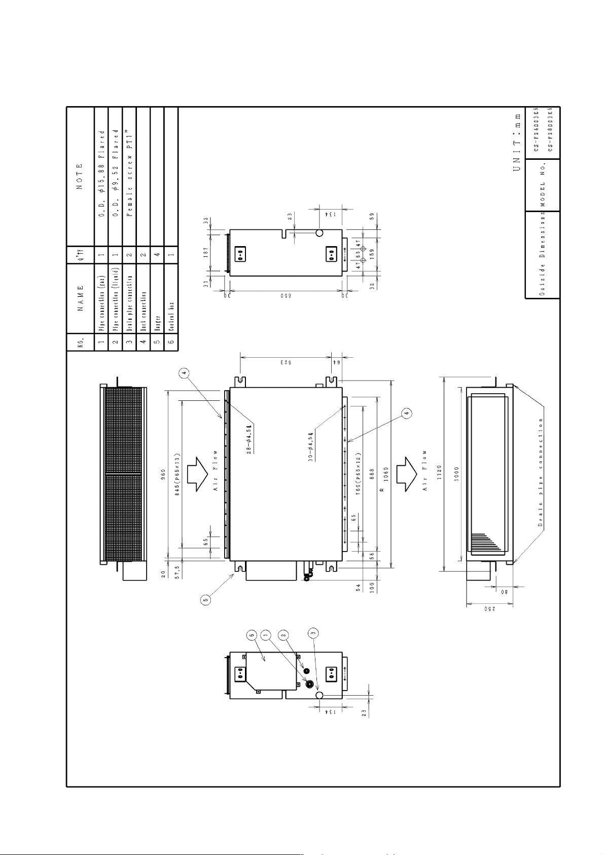
4.1. CS-F24DD3E5 CS-F28DD3E5
4.2. CS-F34DD3E5 CS-F43DD3E5 CS-F50DD3E5
4.3. CU-B24DBE5 CU-B28DBE5 CU-B28DBE8
4.4. CU-B34DBE5 CU-B34DBE8 CU-B43DBE8 CUB50DBE8
5 REFRIGERATION CYCLE
5.1. CS-F24DD3E5 CU-B24DBE5 CS-F28DD3E5 CUB28DBE5 CU-B28DBE8
5.2. CS-F34DD3E5 CU-B34DBE5 CU-B34DBE8 CSF43DD3E5 CU-B43DBE8 CS-F50DD3E5 CU-B50DBE8
6 BLOCK DIAGRAM
6.1. CS-F24DD3E5 CS-F28DD3E5 CS-F34DD3E5 CSF43DD3E5 CS-F50DD3E5
6.2. CU-B24DBE5 CU-B28DBE5
6.3. CU-B34DBE5
6.4. CU-B28DBE8
6.5. CU-B34DBE8 CU-B43DBE8 CU-B50DBE8
7 WIRING DIAGRAM
7.1. CS-F24DD3E5 CS-F28DD3E5 CS-F34DD3E5 CSF43DD3E5 CS-F50DD3E5
7.2. CU-B24DBE5 CU-B28DBE5
7.3. CU-B28DBE8
7.4. CU-B34DBE5
7.5. CU-B34DBE8 CU-B43DBE8 CU-B50DBE8
8 WIRED REMOTE CONTROL OPERATING INSTRUCTIONS
8.1. Name and function of each part
8.2. Remote control - display
8.3. Remote control - panel
8.4. How to set remote control day and time
8.5. How to select the timer
8.6. Daily timer setting
8.7. Weekly timer setting
9 OPERATION DETAIL
9.1. Cooling operation
7
8
9
10
11
12
13
13
14
15
16
17
17
18
19
19
19
19
20
20
21
21
22
23
24
25
26
26
27
28
29
29
30
31
33
9.2. Heating operation
9.3. Soft dry operation
9.4. Auto operation
9.5. Fan operation
9.6. Normal control
9.7. Operation control
9.8. Protection control
9.9. Test run
10 INSTALLATION INSTRUCTION
10.1. Pipe length
10.2. Position of the centre gravity
10.3. Indoor unit installation
10.4. Outdoor unit installation
10.5. Wired remote controller installation
10.6. Twin systems installation
11 INSTALLATION & SERVICING AIR CONDITIONER
11.1. Outline
11.2. Tools for installing/servicing refrigerant piping
11.3. Refrigerant piping work
11.4. Installation, transferring, servicing
12 TROUBLE SHOOTING GUIDE
12.1. For standard installation
12.2. During twin operation
12.3. During group control operation
12.4. Test operation and self diagnosis
12.5. Emergency operation
12.6. Self-diagnosis error code table
13 TECHNICAL DATA
13.1. Sound data
13.2. Sound measurement point
13.3. Discharge and suction pressure
13.4. Capacity and power consumption
13.5. Fan performance
13.6. Safety device
13.7. Operating characteristics
14 REPLACEMENT PARTS
14.1. Indoor unit
14.2. Outdoor unit
15 PRINT PATTERN
15.1. Indoor unit
15.2. Outdoor unit
33
34
34
34
34
35
36
39
41
42
42
44
45
56
67
74
75
75
76
80
82
86
86
88
90
91
94
95
97
97
103
104
106
129
134
135
136
136
140
147
147
148
2
Page 3
1 SERVICE INFORMATION
Notice of Address setting for NEW Duct / NEW Outdoor Unit.
The new Duct Type / New Outdoor models are possible to have address setting for twin control by automatic when main
power supply is switched on.
(Manual address setting is also possible by using Dip switch on Indoor unit P.C. board.) However,
possible when made proper wiring connection and also Indoor unit should be original virgin unit
1.1. Example of trouble at test operation
If found out as following phenomenon at test operation on site, it may have possibility of wrong address setting.
Therefore, please ensure of the address setting.
1. LCD display of wired remote control had not illuminate although the main power supply switch is ‘on’.
2. LCD display had indicated as normal illumination when power supply switch is ‘on’, however outdoor unit cannot be operated.
(But, it is necessary to take 3 to 5 minutes for outdoor unit to start from the timing of remote control ON/OFF switch is ‘on’.)
3. P.C. board had memorized wrong setting information.
a. If main power supply is switched ‘on’ with the wrong connection.
b. When changing the connection or combination of units due to re-installation etc.
• When changing the system from twin control to normal one to one system.
• When making the replacement of units as master and slave etc.
this address setting is only
.
1.2. Caution of test operation
Do not touch the remote control switch and do not change any wirings for one minute when the main power supply switch is ‘on’.
(Because the unit is having automatic address setting during the first one minute.)
1.3. Caution during automatic address setting
When main power supply switch is ‘on’, the P.C. board will automatically memorized the connecting system.
Consequently, when initial power supply is ‘on’, there will not be interchangeability of units even of the same type and same
capacity unit. Therefore unable to connect the unit to another system.
1.4. Operation range
The applicable voltage range for each unit is given in “the following table”. The working voltage among the three phases must be
balanced within 3% deviation from each voltage at the compressor terminals. The starting voltage must be higher than 85% of the
rated voltage.
1.4.1. Power Supply
Model
CU-
B24DBE5
B28DBE5
B34DBE5
B28DBE8
B34DBE8
B43DBE8
B50DBE8
Unit Main Power Applicable Voltage
Phase, Volts Hz Maximum Minimum
1~220 50 242 198
1~230 50 253 207
1~240 50 264 216
3N~380 50 418 342
3N~400 50 440 360
3N~415 50 457 374
1.4.2. Indoor and Outdoor Temperature
Model 50Hz ... B24DBE5, B28DBE5, B28DBE8, B34DBE5, B34DBE8, B43DBE8, B50DBE8
Operating Hz Indoor Temp. (D.B./W.B.) (°C) Outdoor Temp. (D.B./W.B.) (°C)
Maximum Minimum Maximum Minimum
Cooling 50 32/23 21/15 43/- -10/Heating 50 27/- 16/- 24/18 -10/-
3
Page 4

2 FEATURES
2.1. Hide-away type
2.1.1. Compact design
• The height has been reduced to 25 cm, the equipment can
be installed in limited spaces.
2.1.2. Versatile installation
• The indoor unit is designed in order that air will also enter
from below, for easier installation under different conditions.
2.2. Outdoor unit
2.2.1. Flexible installation in smaller
spaces
• Space-saving outdoor unit with the improvement of the
outdoor unit fan makes it possible to install the outdoor unit
into a smaller space where the conventional model cannot
be installed.
• Long pipe design with a maximum piping length of 50m.
• Additional charging of refrigerant are not required for 30m
of pipe length.
• Flexible 4-way piping.
• The equipment has two drain outlets on the right and left
side for adoption to the installation conditions in the
building.
2.1.3. Easy maintenance
• Equipped with a filter as standard. The filter can be
removed in three directions for easier maintenance.
• Centralized drain method gather multiple outdoor units’
drain pipes into a single drain pipe to make installation
easier and also improve appearance.
• Side-by-side continuous installation is possible even for
outdoor units with different capacities.
4
Page 5
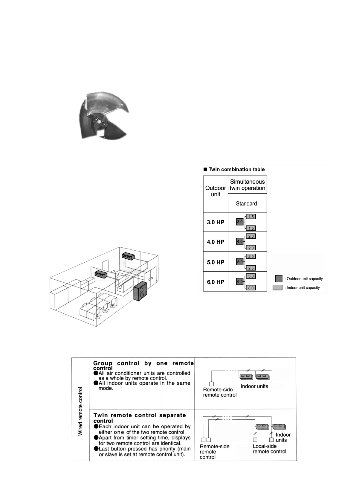
2.2.2. Quiet, efficient design
• A host of silencing technologies achieves super-quiet
operation.
• The noise-suppressing winglet fan is a result of new
research into vane design theory. The unique curved shape
suppresses the generation of vortexes, thus reduces air
flows noise.
• Operating efficiency is improved and energy consumption is
reduced.
2.2.3. Low ambient cooling operation
• The unit can set for cooling even when the outdoor
temperature drops to -10°C. This is ideal for locations that
require cooling even in winter.
2.3. A brand-new control method using the latest in technology
2.3.1. Twin operation
• Simultaneous air conditioning of wide spaces and corners is
possible. Indoor units of same horsepowers and models
can even be used in combination.
• Master unit and slave-units can be set automatically in twin
systems. No address setting is necessary.
• Multiple indoor units can be operated simultaneously with a
single remote control. Note that individual operation is not
possible.
2.3.2. Group control equipment
5
Page 6
3 SPECIFICATION
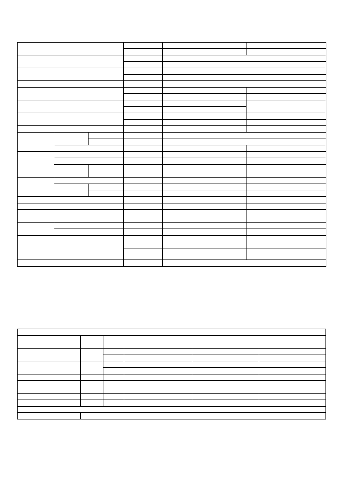
3.1. CS-F24DD3E5 CU-B24DBE5
ITEM / MODEL Indoor Unit Outdoor Unit
Main Body CS-F24DD3E5 CU-B24DBE5
Cooling Capacity kW 6.6
BTU/h 22,500
Heating Capacity kW 7.1
BTU/h 24,200
Refrigerant Charge-less m 30
Standard Air Volume for High Speed m3/min Hi 22 Hi 60
cfm Hi 777 Hi 2120
External Static Pressure Pa Hi 50 -
mmAq Hi 5.1
Outside Dimension (H x W x D) mm 250 x 1000 x 650 795 x 900 x 320
inch 9-26/32 x 39-5/16 x 25-18/32 31-5/16 x 35-7/16 x 12-19/32
Net Weight kg (lbs) 41 (91) 69 (152)
Piping
Connection
Compressor Type, Number of Set - Hermetic, 1
Fan Type, Number of Set Sirocco fan, 2 Mix flow fan - 1
Air-heat Exchanger (Row x Stage x FPI) Louvre-fin type (3 x 12 x 15) Corrugate-fin type (2 x 36 x 19)
Refrigerant Control - Exp. Valve
Refrigerant Oil (Charged) cm
Refrigerant (Charged) R410A kg (oz) - 1.7 (60)
Running
Adjustment
Noise Level dB (A) Cooling : Hi 43 Lo 39 Cooling 50, Heating 51
Moisture Removal L/h (Pt/h) 3.8 (8.0)
Refrigerant Gas mm (inch) O.D Ø 15.88 (5/8) Flared Type
Liquid mm (inch) O.D Ø 9.53 (3/8) Flared Type
Drain mm Female screw RC1 (PT1) I.D Ø 20 x 1
Starting Method - Permanent Split Capacitor
Motor Type - 2-pole single phase brushless motor
Rated Output kW - 2.2
Motor Type 4-pole single phase induction motor 6-pole single phase induction motor
Rated Output kW 0.085 0.07
3
Control Switch Wired Remote Control Room Temperature Thermostat -
Heating : Hi 43 Lo 39
Power level dB Cooling : Hi 59 Lo 55
Heating : Hi 59 Lo 55
- FV50S (1130)
Cooling 66, Heating 67
1. Cooling capacities are based on indoor temperature of 27°C D.B. (80.6°F D.B.), 19.0°C W.B. (66.2°F W.B.) and outdoor air
temperature of 35°C D.B. (95°F D.B.), 24°C W.B. (75.2°F W.B.)
2. Heating capacities are based on indoor temperature 20°C D.B. (68°F D.B.) and outdoor air temperature of 7°C D.B. (44.6°F
D.B.), 6°C W.B. (42.8°F W.B.)
ELECTRICAL DATA (50 Hz)
ITEM / MODEL Condition by ISO5151
Volts V 220 230 240
Phase Single Single Single
Power Consumption kW Cool 2.56 2.59 2.64
Heat 2.4 2.47 2.56
Running Current A Cool 12.7 12.9 13.1
Heat 11.5 11.8 12.3
Starting Current A 59 62 65
Power Factor % Cool 92 87 84
Heat 95 91 87
EER W/W 2.58 2.55 2.50
COP W/W 2.96 2.87 2.77
*Power Factor means total figure of compressor, indoor fan motor and outdoor fan motor.
Panasonic Power source AC, 1~220V, 230V, 240V 50Hz
6
Page 7

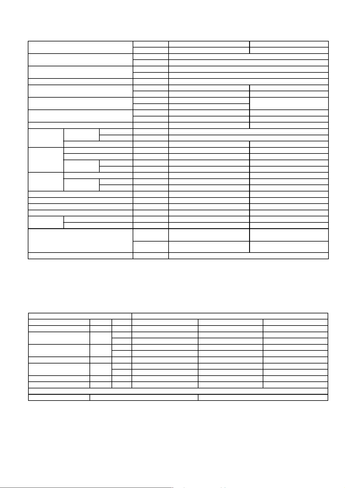
3.2. CS-F28DD3E5 CU-B28DBE5
ITEM / MODEL Indoor Unit Outdoor Unit
Main Body CS-F28DD3E5 CU-B28DBE5
Cooling Capacity kW 7.3
BTU/h 24,900
Heating Capacity kW 8.0
BTU/h 27,300
Refrigerant Charge-less m 30
Standard Air Volume for High Speed m3/min Hi 22 Hi 63
cfm Hi 777 Hi 2226
External Static Pressure Pa Hi 50 -
mmAq Hi 5.1
Outside Dimension (H x W x D) mm 250 x 1000 x 650 795 x 900 x 320
inch 9-26/32 x 39-5/16 x 25-18/32 31-5/16 x 35-7/16 x 12-19/32
Net Weight kg (lbs) 41 (91) 69 (152)
Piping
Connection
Compressor Type, Number of Set - Hermetic, 1
Fan Type, Number of Set Sirocco Fan, 2 Mix flow fan - 1
Air-heat Exchanger (Row x Stage x FPI) Louvre-fin type (3 x 12 x 15) Corrugate-fin type (2 x 36 x 19)
Refrigerant Control - Exp. Valve
Refrigerant Oil (Charged) cm
Refrigerant (Charged) R410A kg (oz) - 2.05 (72)
Running
Adjustment
Noise Level dB (A) Cooling : Hi 43 Lo 39 Cooling 52, Heating 53
Moisture Removal L/h (Pt/h) 4.3 (9.0)
Refrigerant Gas mm (inch) O.D Ø 15.88 (5/8) Flared Type
Liquid mm (inch) O.D Ø 9.53 (3/8) Flared Type
Drain mm Female screw RC1 (PT1) I.D Ø 20 x 1
Starting Method - Permanent Split Capacitor
Motor Type - 2-pole single phase brushless motor
Rated Output kW - 2.2
Motor Type 4-pole single phase induction motor 6-pole single phase induction motor
Rated Output kW 0.085 0.07
3
Control Switch Wired Remote Control Room Temperature Thermostat -
Heating : Hi 43 Lo 39
Power level dB Cooling : Hi 59 Lo 55
Heating : Hi 59 Lo 55
- FV50S (1130)
Cooling 67, Heating 68
1. Cooling capacities are based on indoor temperature of 27°C D.B. (80.6°F D.B.), 19.0°C W.B. (66.2°F W.B.) and outdoor air
temperature of 35°C D.B. (95°F D.B.), 24°C W.B. (75.2°F W.B.)
2. Heating capacities are based on indoor temperature of 20°C D.B. (68°F D.B.) and outdoor air temperature of 7°C D.B. (44.6°F
D.B.), 6°C W.B. (42.8°F W.B.)
ELECTRICAL DATA (50 Hz)
ITEM / MODEL Condition by ISO5151
Volts V 220 230 240
Phase Single Single Single
Power Consumption kW Cool 2.78 2.84 2.89
Heat 2.61 2.69 2.78
Running Current A Cool 13.3 13.5 13.7
Heat 12.5 12.6 13.1
Starting Current A 62 65 68
Power Factor % Cool 95 91 88
Heat 95 93 88
EER W/W 2.63 2.57 2.53
COP W/W 3.07 2.97 2.88
*Power Factor means total figure of compressor, indoor fan motor and outdoor fan motor.
Panasonic Power source AC, 1~220V, 230V, 240V 50Hz
7
Page 8
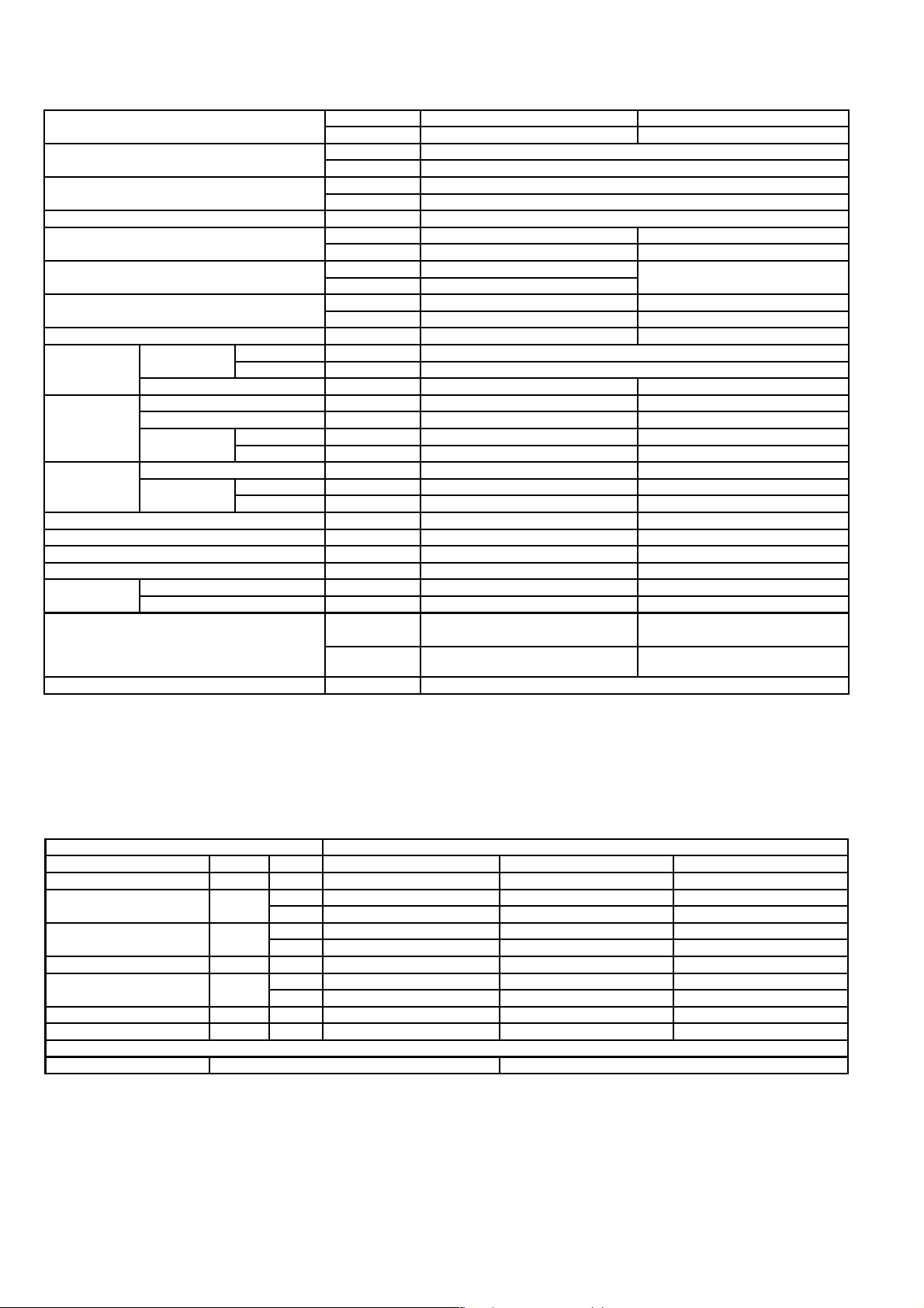
3.3. CS-F28DD3E5 CU-B28DBE8
ITEM / MODEL Indoor Unit Outdoor Unit
Main Body CS-F28DD3E5 CU-B28DBE8
Cooling Capacity kW 7.3
BTU/h 24,900
Heating Capacity kW 8.0
BTU/h 27,300
Refrigerant Charge-less m 30
Standard Air Volume for High Speed m3/min Hi 22 Hi 63
cfm Hi 777 Hi 2226
External Static Pressure Pa Hi 50 -
mmAq Hi 5.1
Outside Dimension (H x W x D) mm 250 x 1000 x 650 795 x 900 x 320
inch 9-26/32 x 39-5/16 x 25-18/32 31-5/16 x 35-7/16 x 12-19/32
Net Weight kg (lbs) 41 (91) 69 (152)
Piping
Connection
Compressor Type, Number of Set - Hermetic, 1
Fan Type, Number of Set Sirocco Fan, 2 Mix flow fan - 1
Air-heat Exchanger (Row x Stage x FPI) Louvre-fin type (3 x 12 x 15) Corrugate-fin type (2 x 36 x 19)
Refrigerant Control - Exp. Valve
Refrigerant Oil (Charged) cm
Refrigerant (Charged) R410A kg (oz) - 2.05 (72)
Running
Adjustment
Noise Level dB (A) Cooling : Hi 43 Lo 39 Cooling 52, Heating 53
Moisture Removal L/h (Pt/h) 4.3 (9.0)
Refrigerant Gas mm (inch) O.D Ø 15.88 (5/8) Flared Type
Liquid mm (inch) O.D Ø 9.53 (3/8) Flared Type
Drain mm Female screw RC1 (PT1) I.D Ø 20 x 1
Starting Method - Permanent Split Capacitor
Motor Type - 2-pole single phase brushless motor
Rated Output kW - 2.2
Motor Type 4-pole single phase induction motor 6-pole single phase induction motor
Rated Output kW 0.085 0.07
3
Control Switch Wired Remote Control Room Temperature Thermostat -
Heating : Hi 43 Lo 39
Power level dB Cooling : Hi 59 Lo 55
Heating : Hi 59 Lo 55
- FV50S (1130)
Cooling 67, Heating 68
1. Cooling capacities are based on indoor temperature of 27°C D.B. (80.6°F D.B.), 19.0°C W.B. (66.2°F W.B.) and outdoor air
temperature of 35°C D.B. (95°F D.B.), 24°C W.B. (75.2°F W.B.)
2. Heating capacities are based on indoor temperature of 20°C D.B. (68°F D.B.) and outdoor air temperature of 7°C D.B. (44.6°F
D.B.), 6°C W.B. (42.8°F W.B.)
ELECTRICAL DATA (50 Hz)
ITEM / MODEL Condition by ISO5151
Volts V 380 400 415
Phase 3N 3N 3N
Power Consumption kW Cool 2.78 2.84 2.89
Heat 2.61 2.69 2.78
Running Current A Cool 4.85 4.9 4.95
Heat 4.65 4.7 4.75
Starting Current A 23 25 27
Power Factor % Cool 87 84 81
Heat 85 83 82
EER W/W 2.63 2.57 2.53
COP W/W 3.07 2.97 2.88
*Power Factor means total figure of compressor, indoor fan motor and outdoor fan motor.
Panasonic Power source AC, 3N~380V, 400V, 415V 50Hz
8
Page 9
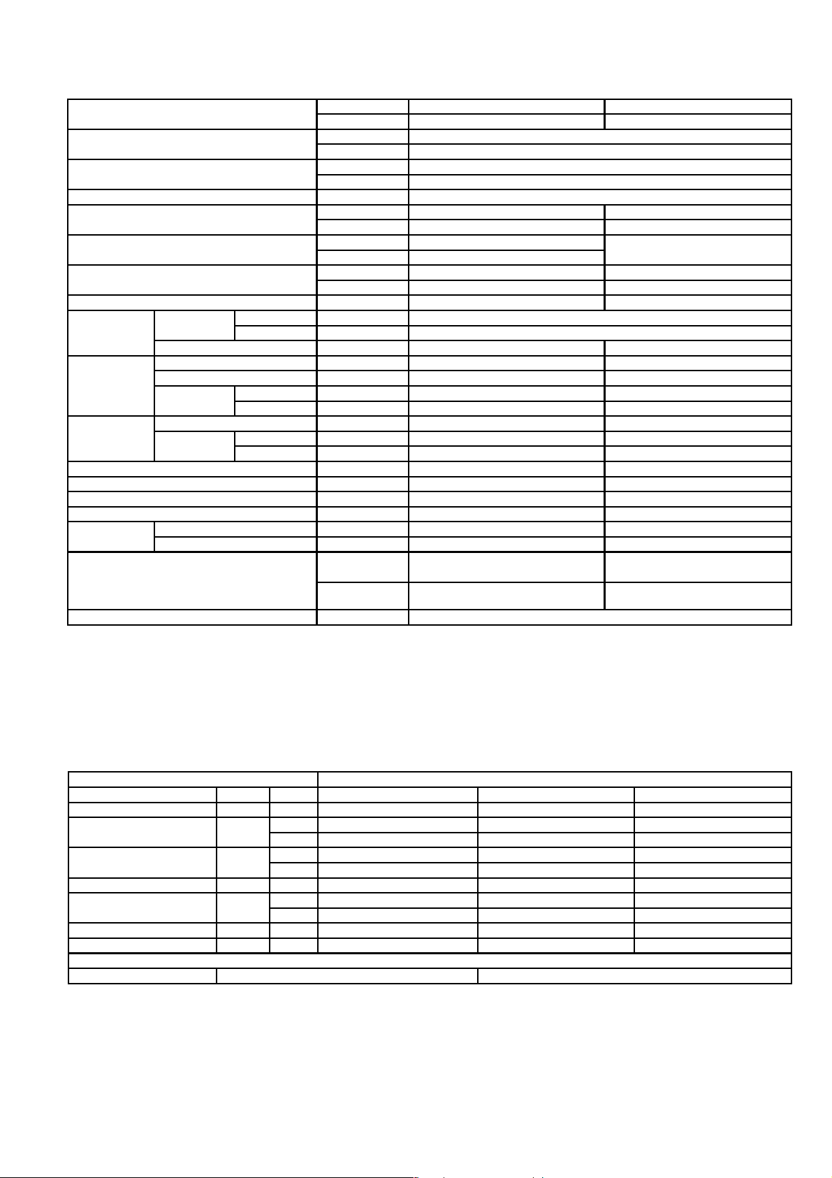
3.4. CS-F34DD3E5 CU-B34DBE5
ITEM / MODEL Indoor Unit Outdoor Unit
Main Body CS-F34DD3E5 CU-B34DBE5
Cooling Capacity kW 10.0
BTU/h 34,100
Heating Capacity kW 11.2
BTU/h 38,200
Refrigerant Charge-less m 30
Standard Air Volume for High Speed m3/min Hi 36 Hi 94
cfm Hi 1271 Hi 3316
External Static Pressure Pa Hi 50 -
mmAq Hi 5.1
Outside Dimension (H x W x D) mm 250 x 1200 x 650 1170 x 900 x 320
inch 9-27/32 x 47-7/32 x 25-19/32 46-1/16 x 35-7/16 x 12-19/32
Net Weight kg (lbs) 47 (104) 102 (225)
Piping
Connection
Compressor Type, Number of Set - Hermetic, 1
Fan Type, Number of Set Sirocco fan, 3 Mix flow fan - 2
Air-heat Exchanger (Row x Stage x FPI) Louvre-fin type (3 x 16 x 15) Corrugate-fin type (2 x 44 x 20)
Refrigerant Control - Exp. Valve
Refrigerant Oil (Charged) cm
Refrigerant (Charged) R410A kg (oz) - 2.7 (95)
Running
Adjustment
Noise Level dB (A) Cooling : Hi 45 Lo 41 Cooling 55, Heating 56
Moisture Removal L/h (Pt/h) 6.0 (12.6)
Refrigerant Gas mm (inch) O.D Ø 15.88 (5/8) Flared Type
Liquid mm (inch) O.D Ø 9.53 (3/8) Flared Type
Drain mm Female screw RC1 (PT1) I.D Ø 20 x 1
Starting Method - Permanent Split Capacitor
Motor Type - 2-pole single phase brushless motor
Rated Output kW - 3.0
Motor Type 4-pole single phase induction motor 6-pole single phase induction motor
Rated Output kW 0.185 0.07 x 2
3
Control Switch Wired Remote Control Room Temperature Thermostat -
Heating : Hi 44 Lo 40
Power level dB Cooling : Hi 60 Lo 56
Heating : Hi 59 Lo 55
- FV68D (1500)
Cooling 69, Heating 70
1. Cooling capacities are based on indoor temperature of 27°C D.B. (80.6°F D.B.), 19.0°C W.B. (66.2°F W.B.) and outdoor air
temperature of 35°C D.B. (95°F D.B.), 24°C W.B. (75.2°F W.B.)
2. Heating capacities are based on indoor temperature 20°C D.B. (68°F D.B.) and outdoor air temperature of 7°C D.B. (44.6°F
D.B.), 6°C W.B. (42.8°F W.B.)
ELECTRICAL DATA (50 Hz)
ITEM / MODEL Condition by ISO5151
Volts V 220 230 240
Phase Single Single Single
Power Consumption kW Cool 3.83 3.88 4.05
Heat 3.86 3.94 4.0
Running Current A Cool 18.4 18.6 18.8
Heat 18.5 18.6 18.9
Starting Current A 92 95 98
Power Factor % Cool 95 91 90
Heat 95 92 88
EER W/W 2.61 2.58 2.47
COP W/W 2.9 2.84 2.8
*Power Factor means total figure of compressor, indoor fan motor and outdoor fan motor.
Panasonic Power source AC, 1~220V, 230V, 240V 50Hz
9
Page 10
3.5. CS-F34DD3E5 CU-B34DBE8
ITEM / MODEL Indoor Unit Outdoor Unit
Main Body CS-F34DD3E5 CU-B34DBE8
Cooling Capacity kW 10.0
BTU/h 34,100
Heating Capacity kW 11.2
BTU/h 38,200
Refrigerant Charge-less m 30
Standard Air Volume for High Speed m3/min Hi 36 Hi 94
cfm Hi 1271 Hi 3316
External Static Pressure Pa Hi 50 -
mmAq Hi 5.1
Outside Dimension (H x W x D) mm 250 x 1200 x 650 1170 x 900 x 320
inch 9-27/32 x 47-7/32 x 25-19/32 46-1/16 x 35-7/16 x 12-19/32
Net Weight kg (lbs) 47 (104) 100 (221)
Piping
Connection
Compressor Type, Number of Set - Hermetic, 1
Fan Type, Number of Set Sirocco fan, 3 Mix flow fan - 2
Air-heat Exchanger (Row x Stage x FPI) Louvre-fin type (3 x 16 x 15) Corrugate-fin type (2 x 44 x 20)
Refrigerant Control - Exp. Valve
Refrigerant Oil (Charged) cm
Refrigerant (Charged) R410A kg (oz) - 2.7 (95)
Running
Adjustment
Noise Level dB (A) Cooling : Hi 45 Lo 41 Cooling 55, Heating 56
Moisture Removal L/h (Pt/h) 6.0 (12.6)
Refrigerant Gas mm (inch) O.D Ø 15.88 (5/8) Flared Type
Liquid mm (inch) O.D Ø 9.53 (3/8) Flared Type
Drain mm Female screw RC1 (PT1) I.D Ø 20 x 1
Starting Method - Permanent Split Capacitor
Motor Type - 2-pole single phase brushless motor
Rated Output kW - 3.0
Motor Type 4-pole single phase induction motor 6-pole single phase induction motor
Rated Output kW 0.185 0.07 x 2
3
Control Switch Wired Remote Control Room Temperature Thermostat -
Heating : Hi 44 Lo 40
Power level dB Cooling : Hi 60 Lo 56
Heating : Hi 59 Lo 55
- FV68D (1500)
Cooling 69, Heating 70
1. Cooling capacities are based on indoor temperature of 27°C D.B. (80.6°F D.B.), 19.0°C W.B. (66.2°F W.B.) and outdoor air
temperature of 35°C D.B. (95°F D.B.), 24°C W.B. (75.2°F W.B.)
2. Heating capacities are based on indoor temperature 20°C D.B. (68°F D.B.) and outdoor air temperature of 7°C D.B. (44.6°F
D.B.), 6°C W.B. (42.8°F W.B.)
ELECTRICAL DATA (50 Hz)
ITEM / MODEL Condition by ISO5151
Volts V 380 400 415
Phase 3N 3N 3N
Power Consumption kW Cool 3.7 3.75 3.8
Heat 3.54 3.58 3.64
Running Current A Cool 6.35 6.45 6.55
Heat 6.10 6.20 6.30
Starting Current A 41 44 47
Power Factor % Cool 89 84 81
Heat 88 83 80
EER W/W 2.70 2.67 2.63
COP W/W 3.16 3.13 3.08
*Power Factor means total figure of compressor, indoor fan motor and outdoor fan motor.
Panasonic Power source AC, 3N~380V, 400V, 415V 50Hz
10
Page 11
3.6. CS-F43DD3E5 CU-B43DBE8
ITEM / MODEL Indoor Unit Outdoor Unit
Main Body CS-F43DD3E5 CU-B43DBE8
Cooling Capacity kW 12.5
BTU/h 42,600
Heating Capacity kW 14.0
BTU/h 47,700
Refrigerant Charge-less m 30
Standard Air Volume for High Speed m3/min Hi 40 Hi 94
cfm Hi 1413 Hi 3316
External Static Pressure Pa Hi 50 -
mmAq Hi 5.1
Outside Dimension (H x W x D) mm 250 x 1200 x 650 1170 x 900 x 320
inch 9-27/32 x 47-7/32 x 25-19/32 46-1/16 x 35-7/16 x 12-19/32
Net Weight kg (lbs) 47 (104) 102 (225)
Piping
Connection
Compressor Type, Number of Set - Hermetic, 1
Fan Type, Number of Set Sirocco Fan, 3 Mix flow fan - 2
Air-heat Exchanger (Row x Stage x FPI) Louvre-fin type (3 x 16 x 15) Corrugate-fin type (2 x 44 x 20)
Refrigerant Control - Exp. Valve
Refrigerant Oil (Charged) cm
Refrigerant (Charged) R410A kg (oz) - 3.10 (109)
Running
Adjustment
Noise Level dB (A) Cooling : Hi 45 Lo 41 Cooling 56, Heating 57
Moisture Removal L/h (Pt/h) 7.9 (16.6)
Refrigerant Gas mm (inch) O.D Ø 15.88 (5/8) Flared Type
Liquid mm (inch) O.D Ø 9.53 (3/8) Flared Type
Drain mm Female screw RC1 (PT1) I.D Ø 20 x 1
Starting Method - Permanent Split Capacitor
Motor Type - 2-pole single phase brushless motor
Rated Output kW - 3.75
Motor Type 4-pole single phase induction motor 6-pole single phase induction motor
Rated Output kW 0.185 0.07 x 2
3
Control Switch Wired Remote Control Room Temperature Thermostat -
Heating : Hi 44 Lo 40
Power level dB Cooling : Hi 60 Lo 56
Heating : Hi 59 Lo 55
- FV68D (1500)
Cooling 70, Heating 71
1. Cooling capacities are based on indoor temperature of 27°C D.B. (80.6°F D.B.), 19.0°C W.B. (66.2°F W.B.) and outdoor air
temperature of 35°C D.B. (95°F D.B.), 24°C W.B. (75.2°F W.B.)
2. Heating capacities are based on indoor temperature of 20°C D.B. (68°F D.B.) and outdoor air temperature of 7°C D.B. (44.6°F
D.B.), 6°C W.B. (42.8°F W.B.)
ELECTRICAL DATA (50 Hz)
ITEM / MODEL Condition by ISO5151
Volts V 380 400 415
Phase 3N 3N 3N
Power Consumption kW Cool 4.75 4.8 4.87
Heat 4.61 4.68 4.78
Running Current A Cool 8.0 8.1 8.2
Heat 7.8 7.9 8.0
Starting Current A 54 57 60
Power Factor % Cool 90 86 83
Heat 90 86 83
EER W/W 2.63 2.60 2.57
COP W/W 3.04 2.99 2.93
*Power Factor means total figure of compressor, indoor fan motor and outdoor fan motor.
Panasonic Power source AC, 3N~380V, 400V, 415V 50Hz
11
Page 12

3.7. CS-F50DD3E5 CU-B50DBE8
ITEM / MODEL Indoor Unit Outdoor Unit
Main Body CS-F50DD3E5 CU-B50DBE8
Cooling Capacity kW 13.5
BTU/h 46,000
Heating Capacity kW 15.0
BTU/h 51,100
Refrigerant Charge-less m 30
Standard Air Volume for High Speed m3/min Hi 44 Hi 96
cfm Hi 1555 Hi 3387
External Static Pressure Pa Hi 50 -
mmAq Hi 5.1
Outside Dimension (H x W x D) mm 250 x 1200 x 650 1170 x 900 x 320
inch 9-27/32 x 47-7/32 x 25-19/32 46-1/16 x 35-7/16 x 12-19/32
Net Weight kg (lbs) 47 (104) 102 (225)
Piping
Connection
Compressor Type, Number of Set - Hermetic, 1
Fan Type, Number of Set Sirocco Fan, 3 Mix flow fan - 2
Air-heat Exchanger (Row x Stage x FPI) Louvre-fin type (3 x 16 x 15) Corrugate-fin type (2 x 44 x 20)
Refrigerant Control - Exp. Valve
Refrigerant Oil (Charged) cm
Refrigerant (Charged) R410A kg (oz) - 3.4 (120)
Running
Adjustment
Noise Level dB (A) Cooling : Hi 46 Lo 42 Cooling 56, Heating 57
Moisture Removal L/h (Pt/h) 8.6 (18.1)
Refrigerant Gas mm (inch) O.D Ø 15.88 (5/8) Flared Type
Liquid mm (inch) O.D Ø 9.53 (3/8) Flared Type
Drain mm Female screw RC1 (PT1) I.D Ø 20 x 1
Starting Method - Permanent Split Capacitor
Motor Type - 2-pole single phase brushless motor
Rated Output kW - 4.5
Motor Type 4-pole single phase induction motor 6-pole single phase induction motor
Rated Output kW 0.185 0.07 x 2
3
Control Switch Wired Remote Control Room Temperature Thermostat -
Heating : Hi 45 Lo 41
Power level dB Cooling : Hi 61 Lo 57
Heating : Hi 60 Lo 56
- FV68D (1500)
Cooling 70, Heating 71
1. Cooling capacities are based on indoor temperature of 27°C D.B. (80.6°F D.B.), 19.0°C W.B. (66.2°F W.B.) and outdoor air
temperature of 35°C D.B. (95°F D.B.), 24°C W.B. (75.2°F W.B.)
2. Heating capacities are based on indoor temperature of 20°C D.B. (68°F D.B.) and outdoor air temperature of 7°C D.B. (44.6°F
D.B.), 6°C W.B. (42.8°F W.B.)
ELECTRICAL DATA (50 Hz)
ITEM / MODEL Condition by ISO5151
Volts V 380 400 415
Phase 3N 3N 3N
Power Consumption kW Cool 5.26 5.31 5.46
Heat 5.03 5.08 5.13
Running Current A Cool 8.7 8.8 9.1
Heat 8.2 8.4 8.7
Starting Current A 55 58 61
Power Factor % Cool 92 87 83
Heat 93 87 82
EER W/W 2.57 2.54 2.47
COP W/W 2.98 2.95 2.92
*Power Factor means total figure of compressor, indoor fan motor and outdoor fan motor.
Panasonic Power source AC, 3N~380V, 400V, 415V 50Hz
12
Page 13
4 DIMENSIONS
4.1. CS-F24DD3E5 CS-F28DD3E5
13
Page 14

4.2. CS-F34DD3E5 CS-F43DD3E5 CS-F50DD3E5
14
Page 15
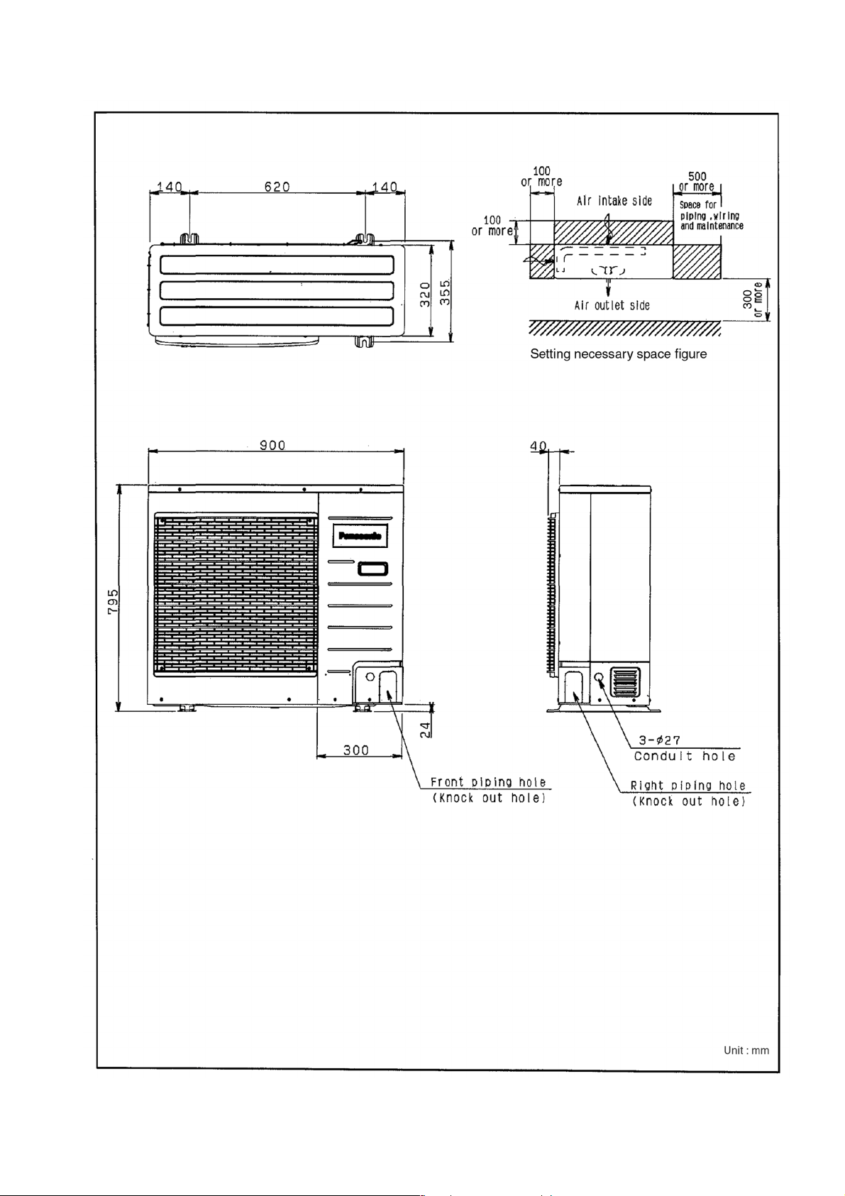
4.3. CU-B24DBE5 CU-B28DBE5 CU-B28DBE8
15
Page 16
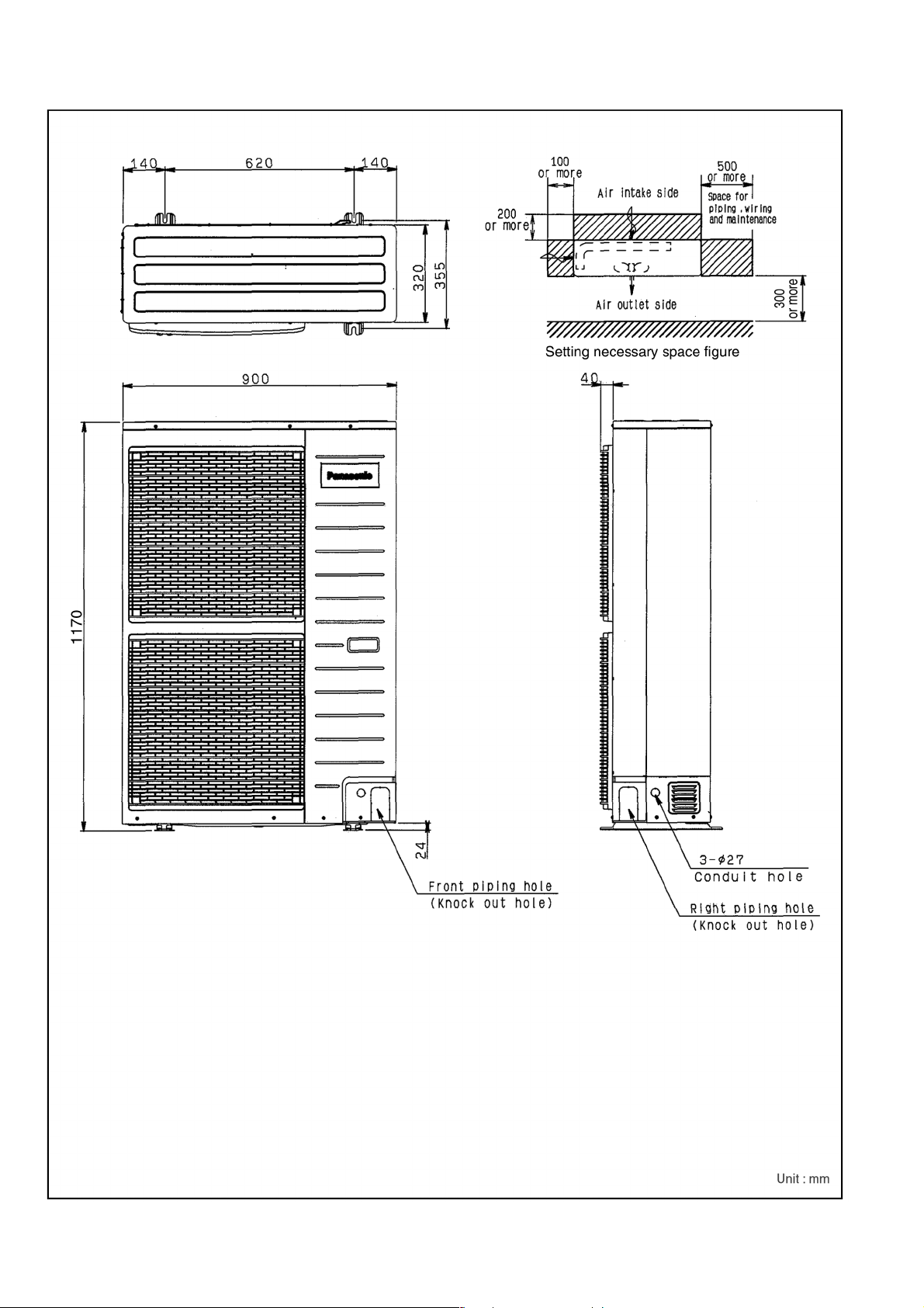
4.4. CU-B34DBE5 CU-B34DBE8 CU-B43DBE8 CU-B50DBE8
16
Page 17
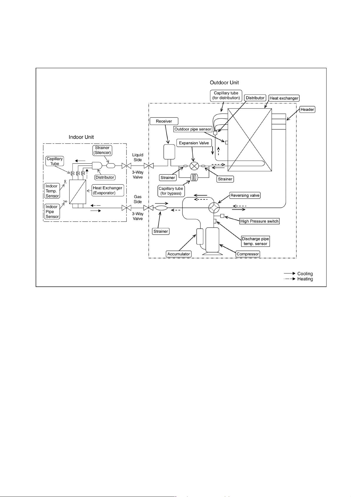
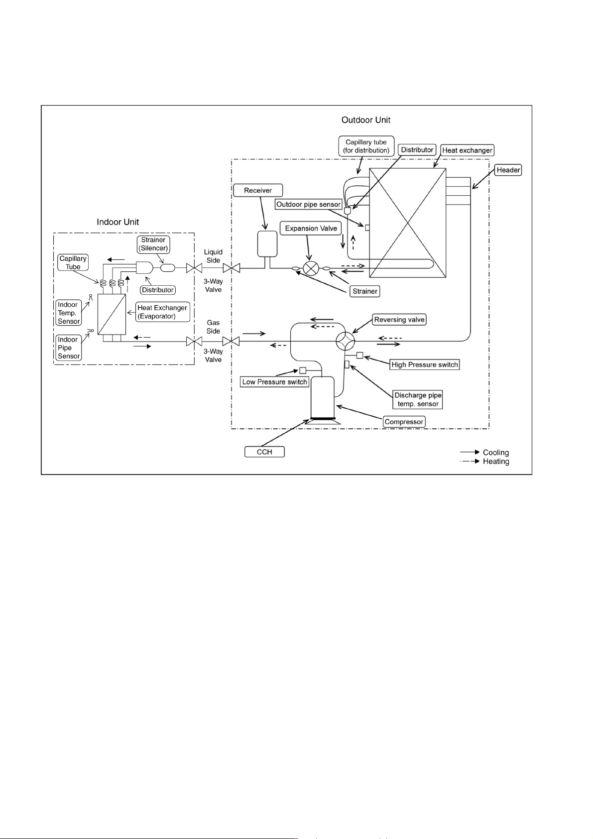
5 REFRIGERATION CYCLE
5.1. CS-F24DD3E5 CU-B24DBE5
CS-F28DD3E5 CU-B28DBE5 CU-B28DBE8
17
Page 18
5.2. CS-F34DD3E5 CU-B34DBE5 CU-B34DBE8
CS-F43DD3E5 CU-B43DBE8
CS-F50DD3E5 CU-B50DBE8
18
Page 19
6 BLOCK DIAGRAM
6.1. CS-F24DD3E5 CS-F28DD3E5 CS-F34DD3E5 CS-F43DD3E5
CS-F50DD3E5
6.2. CU-B24DBE5 CU-B28DBE5
6.3. CU-B34DBE5
19
Page 20

6.4. CU-B28DBE8
6.5. CU-B34DBE8 CU-B43DBE8 CU-B50DBE8
20
Page 21

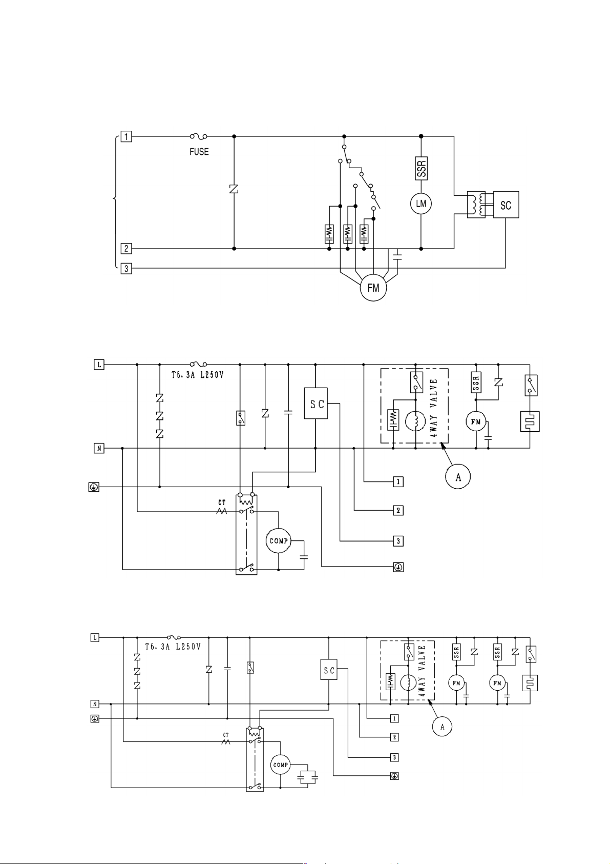
7 WIRING DIAGRAM
7.1. CS-F24DD3E5 CS-F28DD3E5 CS-F34DD3E5 CS-F43DD3E5
CS-F50DD3E5
21
Page 22

7.2. CU-B24DBE5 CU-B28DBE5
22
Page 23
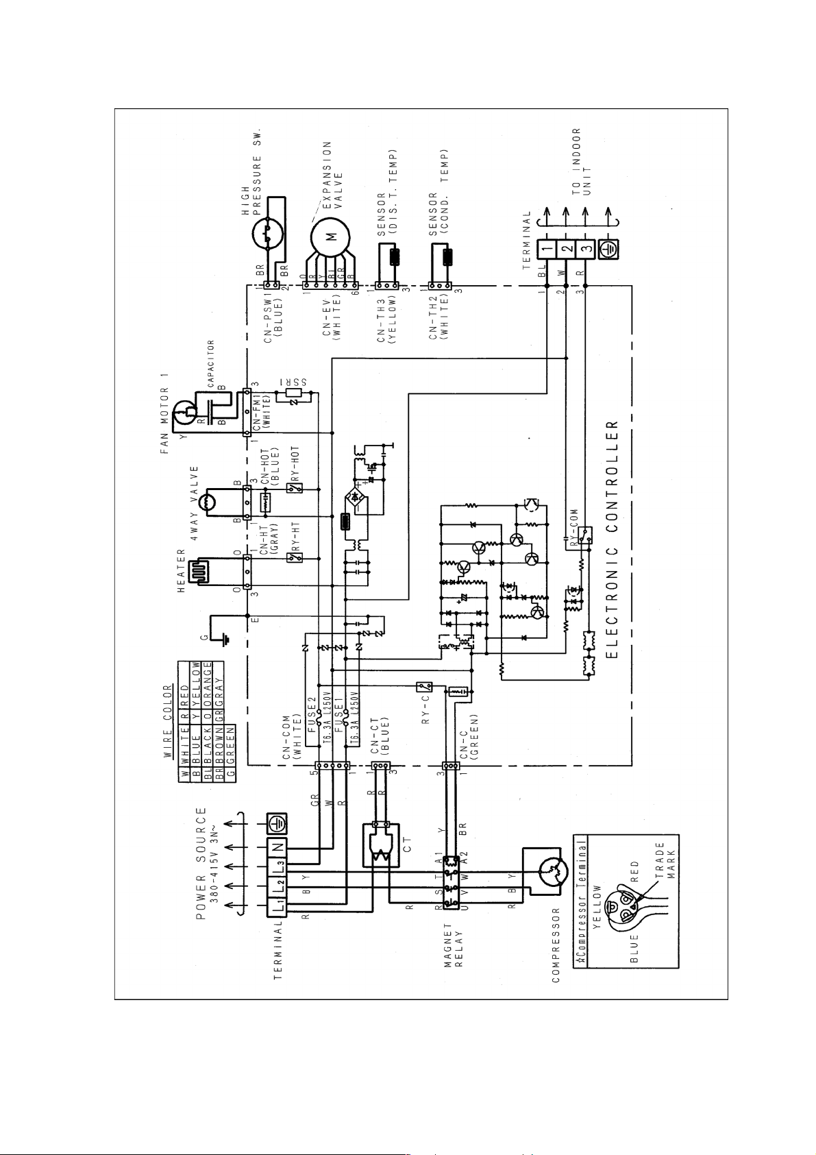
7.3. CU-B28DBE8
23
Page 24
7.4. CU-B34DBE5
24
Page 25

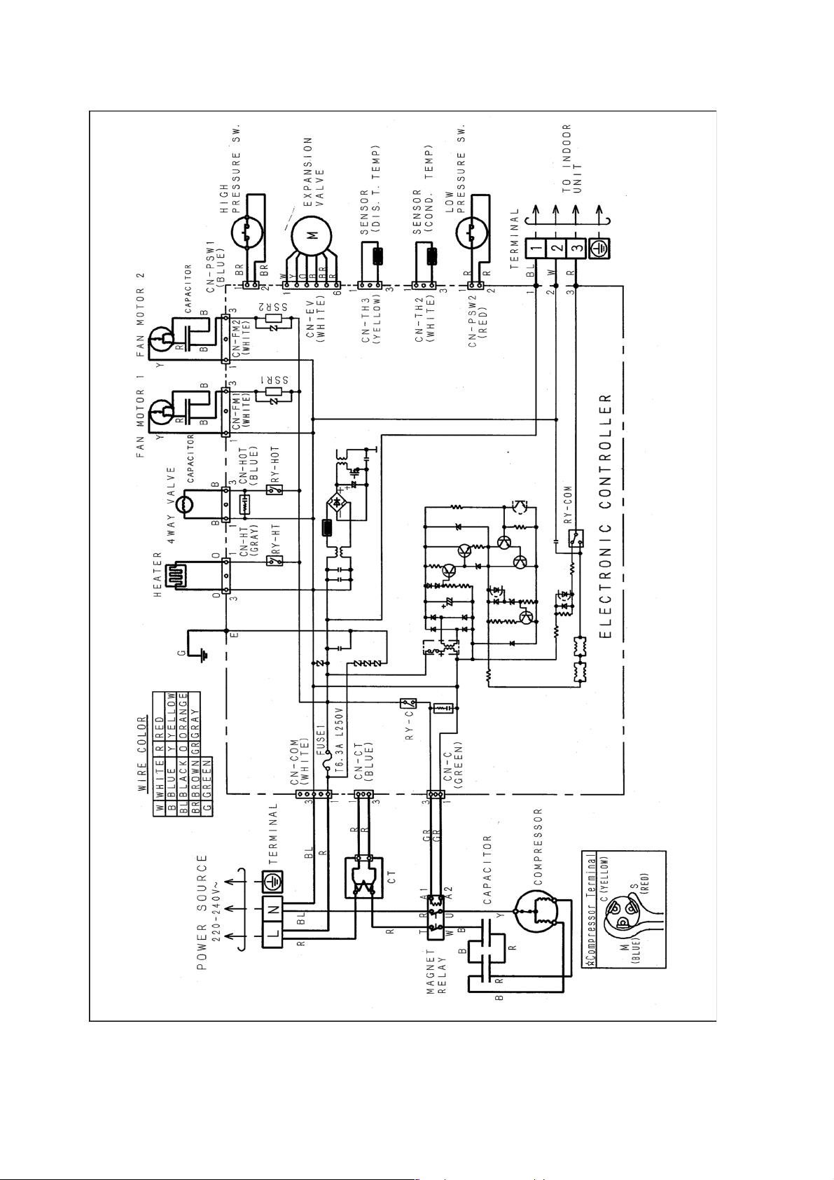
7.5. CU-B34DBE8 CU-B43DBE8 CU-B50DBE8
25
Page 26
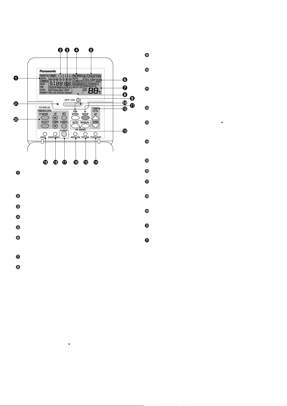
8 WIRED REMOTE CONTROL OPERATING INSTRUCTIONS
8.1. Name and function of each part
OFF/ON button
Used to start and stop the operation.
FAN SPEED button
Used to select the fan speed of high (HI), medium (MED), low
(LO) or auto (AUTO).
MODE button
Used to select the operation of AUTO, HEAT, FAN, COOL, or
DRY.
TEMP (UP/DOWN) buttons
Used to select the desired temperature.
AIR SWING (AUTO/MANUAL) buttons
Used to determined the air swing condition, either auto or
manual.
FILTER RESET button
Press to reset the “FILTER RESET” display after washing the
filter.
TEST RUN button*
REMOTE
The OFF/ON button cannot be used.
LOCAL
All wired remote control buttons can be used.
Time/time setting display
Check display
Fan speed display
Operation mode selection display
FILTER RESET display
(Appears after the cumulative running time reaches
approximately 2,500 hours of operation.)
Temperature setting display (16°C - 31°C)
Airflow direction setting display
VENTILATION button*
ECONOMY operation button
Provides Energy saving function
ODOUR WASH button
Provides deodorizing function.
CHECK button
Press this button if the check display is flashing.
TIMER/CLOCK SET buttons
Used to set the timer operation and the current time.
Operation indicator
Lights up when the unit in operation.
NOTES
Ensure that the correct button is pressed as simultaneous pressing of the multiple buttons will not make the setting correct.
•
The illustration above is for explanatory purposes only. The appearance will be different during actual operation.
•
Do not operate the remote control with wet hands. Otherwise, electric shock or malfunction may occur.
•
Do not press the remote control buttons with sharp object as this may damage the remote control.
•
Buttons marked with * are not needed for normal operation. If one of these buttons is pressed by mistake, press the same
•
button once more to cancel the operation.
When the power resumed after power failure, the unit will restart automatically with all the previous settings preserved by
•
the memory function. (Auto restart function)
Buttons marked with
•
are not available for operation. If one of these buttons is pressed function will not be available.
26
Page 27
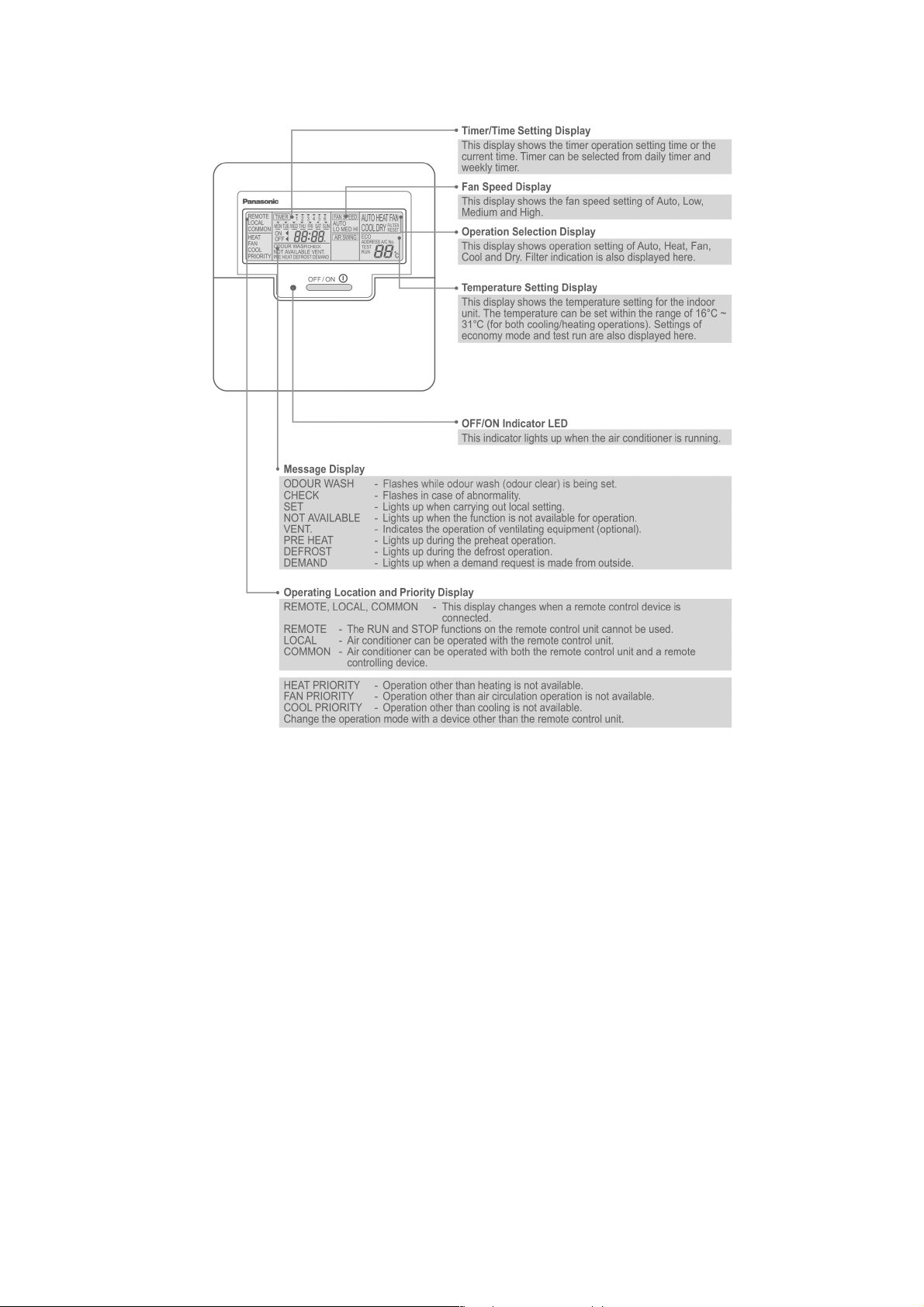
8.2. Remote control - display
27
Page 28
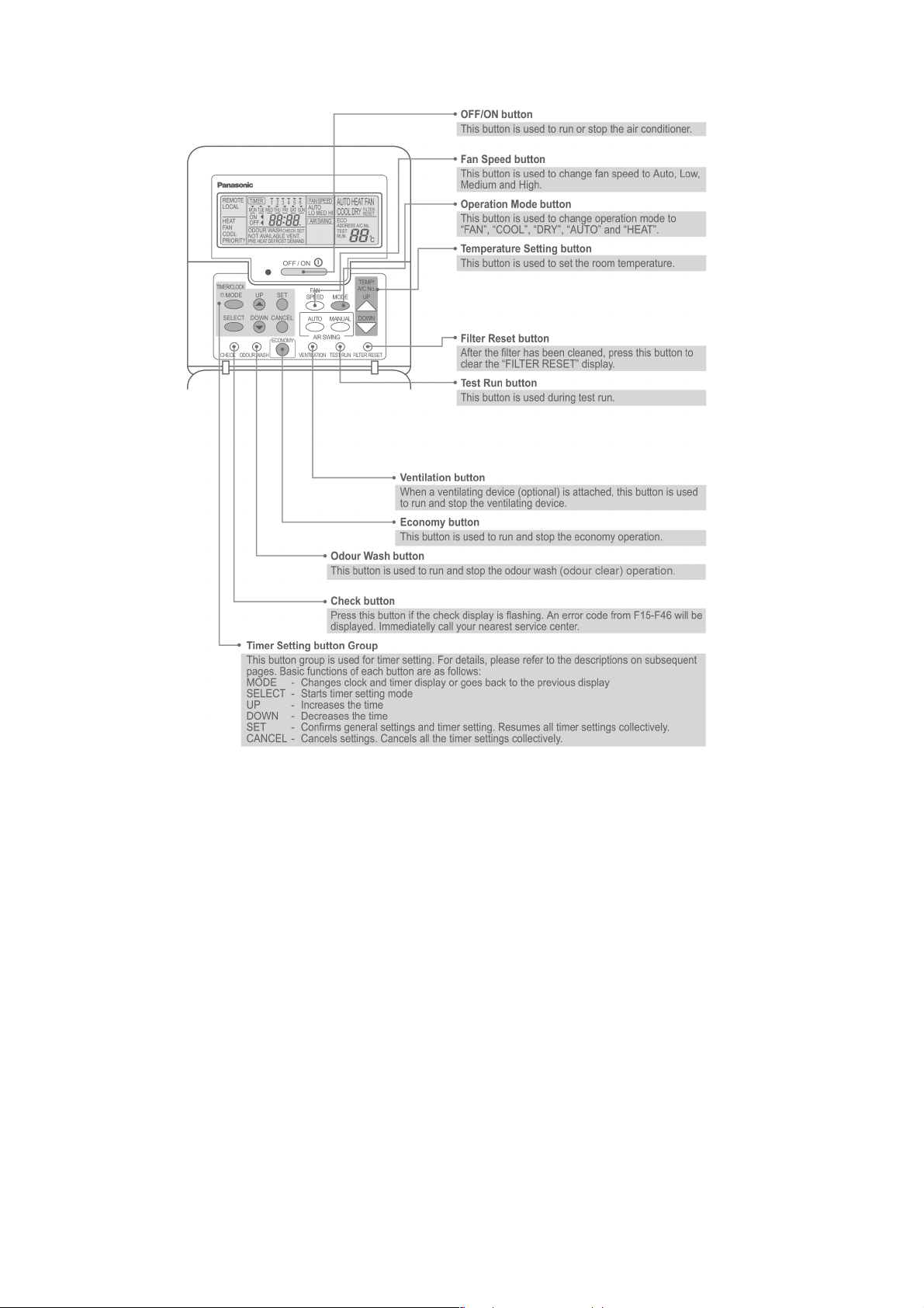
8.3. Remote control - panel
28
Page 29
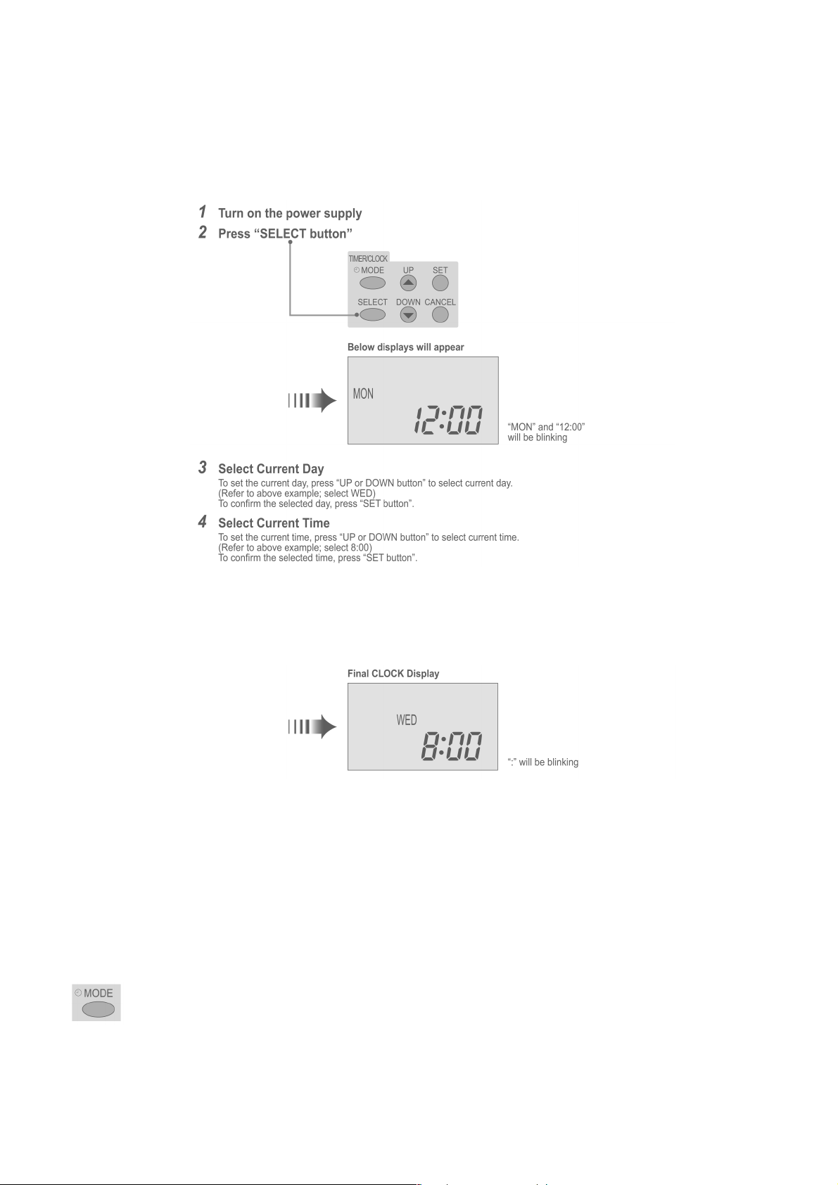
8.4. How to set remote control day and time
• The day and time need to be set when you turn on the power for the first time or after a long time has elapsed since the power
was last turned on.
• The day and time become the standard time for all the Timer operations.
• Set the day and time accurately.
• Example : Current Day is Wednesday and Current Time is 8:00.
Note:
• Press “UP button” to increase or “DOWN button” to decrease (interval 1 minute) or hold the button to change the time faster.
• If the “UP or DOWN button” is not pressed for 30 seconds during the day or time setting or if the “SELECT button” is
pressed, the setting at that moment is confirmed and setting will end.
8.5. How to select the timer
• 2 types of Timer mode can be selected on the remote control.
− Daily Timer
− Weekly Timer
• These timers cannot be operated simultaneously.
• Select one of these Timers for your convenience.
How to Change the Display
• Press once to change the display from CLOCK to Timer or vice-versa.
• Press more than 3 seconds to change the display from Daily Timer to Weekly Timer or vice-versa.
29
Page 30

CLOCK Display (To set current Day and Time)
Note:
• The above display is shown if no valid timer setting is made.
• If valid timer setting is made.
− Timer
and setting will be displayed.
− If you want to check the current time and day, press “MODE button” once.
(However, after a few seconds, the display will change back to Timer
8.6. Daily timer setting
and the setting)
• Display
• How to Set Daily Timer
− You can set only “ON” or only “OFF” or “ON” and “OFF” in a day.
1. Change Display
Press “MODE button” to change the display to daily timer.
2. ON-Timer, OFF-Timer and select Time
Press “SELECT button”; ON-Timer setting will be displayed.
Press “UP or DOWN button” to select the desired time, (Example: ON 9:00), then press “SET button” to confirm
the selected desired time.
Or press “CANCEL button” if you do not want any setting for ON-Timer.
Then OFF-Timer setting will be displayed.
Press “UP or DOWN button” to select the desired time, (Example: OFF 18:30), then press “SET button” to
confirm the selected desired time.
Or press “CANCEL button” if you do not want any setting for OFF-Timer.
Note:
• The setting timer will be activated everyday.
• Timer nearer to the current time will be activated first.
30
Page 31

Final Display of Daily Timer:
8.7. Weekly timer setting
• Display
• How to Set Weekly Timer
− You can set the Timer for 1 week (Monday to Sunday) with 6 programs per day.
− ON-Timer can be set together with your desired temperature. However, this temperature will be used continuously.
− Cannot set 2 programs with same time setting in a day.
− You also may select Collective - many days with same time setting or Individual
− single/one day setting.
1. Change Display
Press “MODE button” to change the display to weekly timer.
2. Select Day (please refer to next page for example of setting)
You may select Collective or Individual day setting.
•
Collective day setting.
Press “SELECT button”: display will show day selection setting.
Press “UP or DOWN button” to select the day. Then press “SET button” to delete triangle mark
(deselect) or add triangle mark (select).
(Triangle mark on top of each day indicates the day to be selected).
Repeat these steps if you want to deselect or select many days.
To confirm the selected days, press the “SELECT button”.
•
Individual day setting.
Press “UP or DOWN button” to select the day.
Then press “SELECT button”.
3. Select Time (please refer to next page for example of setting)
For 1st program setting.
Press “UP or DOWN button” to select ON or OFF.
Then press “SET button” to confirm.
Press “UP or DOWN button” again to select the desired time.
(If you want to set them together with your desired temperature, press “TEMP UP/DOWN button” to
select the temperature).
Then press “SET button” to confirm.
Or press “CANCEL button” if you do not want to set any time.
For 2nd ~ 6th program you may refer to the above step.
31
Page 32

For example, if you want to set:
A - Monday to Friday: Same time, 1st program ON 9:00 & 2nd program OFF 16:00.
B - Only Wednesday: Additional 3rd program OFF 12:30 & 4th program ON 13:30.
C - Only Saturday: 1st program ON 10:00 with 20°C & 2nd program OFF 14:00.
D - Sunday: Holiday. No need to set any Timer.
•
To set A (Monday to Friday - Collective day setting)
Press “SELECT button”
To select Monday to Friday, deselect Saturday and Sunday by pressing “UP or DOWN button” to Saturday, press
“SET button” (triangle mark on top of Saturday will disappear)
Follow the same step to deselect Sunday.
Ensure triangle mark appears on top of Monday ~ Friday.
−
To confirm the selected days, press “SELECT button”.
To set the time, please refer to step 3.
−
1st program - select ON and desired time to 9:00.
2nd program - select OFF and desired time to 16:00.
3rd ~ 6th program - press “CANCEL button”.
•
To set B (Wednesday - Individual day setting)
−
Press “UP or DOWN button” to select WED (Wednesday).
Then press “SELECT button”.
To set the time, please refer to step 3.
−
1st program - press “SET button” twice (confirm ON and 9:00)
2nd program - also press “SET button” twice. (Confirm OFF and 16:00)
3rd program - select OFF and desired time to 12:30
4th program - select ON and desired time to 13:30
5th ~6th program - press “CANCEL button”
•
To set C (Saturday - Individual day setting)
−
Follow the same step as above.
To set the time, please refer to step 3.
−
1st program - select ON, desired time to 10:00 and desired temperature to 20°C.
2nd program - select OFF and desired time to 14:00.
3rd ~ 6th program - press “CANCEL button”.
−
Final Display for Weekly timer may show as:
(Display is showing, 9:00 ON - Timer on Wednesday will be activated next because it is nearest the current
day/time.)
Note:
• Timer that has setting nearest to current time and day will be activated first.
• To check the setting timer, press “SELECT button”, then “UP or DOWN button” to select day. The display will show each
program for the selected day.
• To reset the setting for all, press “SELECT button”, then ensure all day setting with triangle mark. Then press “CANCEL
button” for all the programs.
32
Page 33

9 OPERATION DETAIL
9.1. Cooling operation
• Cooling operation can be set using remote control.
• This operation is applied to cool down the room temperature reaches the setting temperature set on the remote control.
• Cooling Operation Time Diagram.
33
Page 34

9.2. Heating operation
• Heating operation can be set using remote control.
• This operation is applied to warm up the room temperature reaches the setting temperature set on the remote control.
• Heating Operation Time Diagram.
9.3. Soft dry operation
• Soft Dry Operation can be set using remote control.
• Soft Dry operation is applied to dehumidify the room.
• When operation begins, the fan speed is fixed at Low speed while cooling operation is running until reaches the remote control
setting temperature.
9.4. Auto operation
• Automatic Mode can be set using remote control.
• This operation starts to judge the intake air temperature, setting temperature, and outdoor piping temperature. Then the unit
starts to operate at determined operation mode.
9.5. Fan operation
• Fan operation can be set using remote control.
• The indoor fan is operated at High, Medium or Low speed according to remote control setting.
34
Page 35

9.6. Normal control
9.6.1. Cooling Indoor Fan Control
• Manual Fan Speed
Operation starts at High, Medium or Low speed set by remote control.
• Auto Fan Speed
When operation starts, or shifting to thermostat ON condition from thermostat OFF condition, indoor fan operates as below.
Thermostat &
Compressor ON/OFF
Time 40 sec. 50 sec. - 20 sec. 120 sec. 20 sec. 40 sec. 50 sec. -
Cool Auto Off Lo Hi Lo Off Lo Off Lo Me
Soft Dry Auto Off Lo Lo Lo Off Lo Off Lo Lo
9.6.2. Heating Indoor Fan Control
• Manual Fan Speed
Operation starts at High, Medium or Low speed set by remote control.
However, when operation start, or during operation, fan speed control is limited due to prevent a cold draft, for example, when
heating operation start.
Thermostat & Compressor ON Thermostat & Compressor OFF Thermostat & Compressor ON
• Auto Fan Speed
When operation start, or during operation, fan speed control by detecting indoor heat exchanger as follows:
• If thermostat is off, indoor fan fixed low speed.
35
Page 36

9.6.3. Cooling Outdoor Fan Control
• During cooling operation, outdoor fan speed changes according to outdoor pipe temperature.
• The fan speed is controlled by the timing of turning the outdoor fan ON and OFF within an interval.
• When outdoor pipe temperature increases, internal timing also increases.
• Outdoor fan ON time is a variable with the range of 200ms to 2000ms.
• After 2 minutes, the outdoor pipe temperature is detected and the outdoor unit fan speed is changed automatically.
9.6.4. Heating Outdoor Fan Control
• During heating operation, the fan speed is controlled by indoor heat exchanger temperature.
• In case of twin operation, the higher indoor heat exchanger temperature is used to control the fan speed. During heating
operation, the fan speed is controlled by indoor heat exchanger temperature.
9.7. Operation control
9.7.1. Thermostat Control
• Depending on differences between room temperature and setting temperature, compressor operation is decided and starts
operation.
• If temperature difference matches values shown below, thermostat switches off.
Cool Mode -1.5°C
Soft Dry Mode -2.5°C
Heat Mode 3.5°C
9.7.2. Odour Cut Control
• Odour cut operation removes the odour generated at indoor heat exchanger by using drain water come out from indoor heat
exchanger.
• Press “Odour” button at remote control to enable odour cut operation.
• Odour cut operation starts when compressor or thermostat is on.
Thermostat &
Compressor ON/OFF
Time 40 sec. 50 sec. - 20 sec. 120 sec. 20 sec. 40 sec. 50 sec. -
Cool Off Lo Normal
Soft Dry Off Lo Lo Lo Off Lo Off Lo Lo
Thermostat & Compressor ON Thermostat & Compressor OFF Thermostat & Compressor ON
Operation
Lo Off Lo Off Lo Normal
Operation
36
Page 37

9.7.3. Powerful Control
• To achieve setting temperature quickly.
• Cooling powerful operation:
− Setting temperature and thermostat shifting temperature are decrease by 2°C (lower limit 16°C).
− Airflow direction is optimized regardless the air flow setting at remote control.
− Fan speed is optimized at Hi regardless the fan speed setting at remote control.
• Drying powerful operation:
− Setting temperature and thermostat shifting temperature are decrease by 2°C (lower limit 16°C).
− Airflow direction follows remote control setting.
• Heating powerful operation:
− Setting temperature and thermostat shifting temperature are increase by 2°C (upper limit 31°C).
− Airflow direction is optimized regardless the air flow setting at remote control.
− Fan speed is optimized at Hi regardless the fan speed setting at remote control.
• During powerful operation, the powerful indicator lights on.
• Powerful operation cancel when:
− Powerful operates for more than 15 minutes.
− Powerful button is pressed again.
− Operation mode changed.
− Operation stopped by remote control or emergency button.
− OFF timer is activated.
9.7.4. Hot Start Control
• Hot start control operates at the starting of heating operation, where [PREHEAT] displayed at wired remote control.
• Indoor fan stops until hot start control ends (indoor heat exchanger temperature increases or 4 minutes past heating operation
starts), fan control resume.
9.7.5. Energy Save Control
• During Cooling Operation, press "Economy" button at remote control to enable Energy Saving Operation.
• The air conditioner judges the stable condition, where the different between indoor suction temperature and setting temperature
is 1°C for 30 minutes and moderately shifts the set temperature in 0.5°C steps (Maximum 2°C) to control energy saving
operation.
• If temperature different is out of range, energy save operation will not start.
• Energy Save Operation is canceled by pressing the "Economy" button again.
Energy save control time chart
37
Page 38

9.7.6. Dew Form Prevention Control
• During cool or dry operation, if outdoor temperature is less than 30°C, and indoor fan speed is low or auto setting, indoor heat
exchanger temperature become lower, dew form prevention control start to prevent dew form at indoor discharge grill.
• When indoor pipe temperature decrease, cooling capacity will be reduced.
9.7.7. Freeze Prevention Control
• During Cooling or Dry operation, after compressor starts operation for 4 minutes, the outdoor unit will stop its operation if indoor
pipe temperature falls below 0ºC for 6 minutes.
• After 3 minutes stops, compressor restarts operation if indoor pipe temperature is 6ºC or more.
• This phenomenon is to protect the indoor heat exchanger from freezing and to prevent higher volume of refrigerant in liquid from
returning to the compressor.
9.7.8. Deice Control
• During heating operation at low outdoor temperature, deice operation start timely to melt the ice formed on outdoor heat
exchanger.
• During deice operation, in spite of any changes of remote control, indoor fan stop.
• During deice operation, [DEFROST] is displayed at wired remote control, hot start operate after deice operation finish.
• Deice operation start when accumulative heating operation time or after previous deice end reaches 45 minutes, the outdoor
fan maintains Hi status and the outdoor heat exchanger maintains -2°C for 5 minutes.
38
Page 39

9.7.9. Time Delay Safe Control
• The compressor will not start for three minutes after stop of operation.
9.7.10. Outdoor Fan Remaining Heat Removal Control
• When compressor stops, outdoor fan operates at High speed for 1 minute to remove the remaining heat.
9.7.11. Crank Case Heater Control
• Crank case heater ON when the compressor is shutdown and discharge temperature is 20°C to prevents the refrigerant solving
into compressor oil inside the compressor shell at cold condition.
9.7.12. Pump Down
• To enable pump down operation, at outdoor PCB, set the DS1 and DS2 to OFF position.
• Press Test Run button for 1 second. SW1 located at outdoor printed circuit board.
• During Pump Down operation, push the Test Run button again for 1 second to stop the pump down operation.
• The pump down operation runs for 10 minutes.
9.8. Protection control
9.8.1. Outdoor Low-pressure Protection Control
• The purpose of low-pressure protection control is gas leakage detection control.
• The low-pressure protection control starts when low-pressure switch is activated less than 15 minutes after compressor startup.
During heating operation or deice control low-pressure detection does not start.
• During this protection control, compressor is shut down, indoor unit is set to thermo-off status.
• After 6 occasions, suction pressure error is displayed; all operations stopped except outdoor fan remaining heat removal
control.
39
Page 40

9.8.2. Outdoor High-pressure Protection Control
• The high-pressure protection control starts when high-pressure switch is activated less than 15 minutes after compressor
startup.
• During this protection control, compressor is shut down. And indoor unit is set to thermo-off status.
• After 6 occasions, high-pressure protection error is displayed; all operations stopped except outdoor fan remaining heat removal
control.
9.8.3. Discharge Temperature Protection Control
• The discharge temperature protection control starts when abnormal compressor temperature 115°C is detected when outdoor
unit is operating in cooling or heating operation.
• During this protection control, compressor is shut down. And indoor unit is set to thermo-off status.
• After 6 occasions, high-pressure protection error is displayed; all operations stopped except outdoor fan remaining heat removal
control.
9.8.4. Over Current Protection Control
• The purpose of over current protection control is to protect the air conditioner from over current.
• The over current protection control starts when input current from CT is maintained at 20A or more for 2 seconds when the
outdoor unit is starting up or during cooling or heating operation.
• During this protection control, compressor is shut down. And indoor unit is set to thermo-off status.
• After 4 occasions, over current protection error is displayed; all operations stopped except outdoor fan remaining heat removal
control.
9.8.5. CT Disconnection Detection Control
• CT disconnection detection control detects if the CT sensor works normally.
• The CT disconnection detection activates when:
− CT input value is maintained at compressor shutdown status (1.5A or less) consecutively for 2 seconds when the
compressor is operating; except deice mode.
− During this condition, compressor is shut down and indoor unit is set to thermo-off status.
− After 4 occasions, CT sensor error is displayed; all operations stopped except outdoo r fan remaining heat removal
control.
− CT input value is maintained at compressor operation status (5A or more) consecutively for a period of 60 seconds when
the compressor is shut down.
− During this condition, CT sensor error is displayed.
9.8.6. Connection Capacity Protection Control
• The purpose of connection capacity protection control is to ensure the total capacity of connected indoor units is within
acceptable range.
Model Number Min Capacity (kW) Max Capacity (kW) Model Number Min Capacity (kW) Max Capacity (kW)
CU-B14DBE5 5.3 6.9 CU-B28DBE8 6.3 9.8
CU-B18DBE5 5.3 6.9 CU-B34DBE8 7.3 12.3
CU-B24DBE5 6.3 9.8 CU-B43DBE8 10.2 13.8
CU-B28DBE5 7.3 12.3 CU-B50DBE8 12.7 15.8
• During this protection control, connection capacity error is displayed; all operations stopped.
9.8.7. Sensor Disconnection Detection Control
• The sensor disconnection detection control activates when the following condition comply:
Sensor Detection Threshold Duration (Sec) Detection condition
Discharge Temperature < -4.5°C or 201.8°C 5 Other than compressor start control
Outdoor heat exchange < -50.5°C or 103.7°C 5 Regularly
• During sensor disconnection, sensor error is displayed; all operations stops except outdoor fan remaining heat removal control.
40
and compressor ON
Page 41

9.8.8. Four-way Valve Error Detection Control
• The four-way valve error detection control starts when:
− During cooling operation, when indoor heat exchanger temperature exceeds 45°C in 5 minutes after compressor starts.
− During heating operation, when indoor heat exchanger temperature is below 5°C in 5 minutes after compressor starts.
• During four-way valve error, compressor is shut down and indoor unit is set to thermo-off status.
• After 3 occasions, four-way valve error is displayed; all operations stopped except outdoor fan remaining heat removal control.
9.8.9. Valve Error Detection Control
• This control is to protect the compressor.
• Valve error is detected if comply with condition below:
− Power is on for the first time and within 5 minutes from compressor starts (However, the unit is considered power on for first
time when compressor starts operating continuously for 7 minutes).
− Indoor heat exchanger temperature at compressor start -3°C < current heat exchanger temperature for 1 minute.
• During this error, four-way valve error is displayed; compressor is shutdown.
9.8.10. High-pressure Switch Disconnection Error Detection Control
• High-pressure switch disconnection is detected when high-pressure switch input continuously open for 1 minute while the
compressor shutdown.
• During this error, high-pressure switch error is displayed.
9.8.11. Low-pressure Switch Disconnection Error Detection Control
• Low-pressure switch disconnection is detected when low-pressure switch input continuously open for 1 minute while
compressor shutdown.
• During this error, low-pressure switch error is displayed.
9.9. Test run
• Test run is necessary after installation is completed.
• To enable forced cooling test run, at outdoor PCB, set the DS1 to ON position and DS2 to OFF position.
• To enable forced heating test run, at outdoor PCB, set the DS1 to ON position and DS2 to ON position.
• Press Test Run button for 1 second. SW1 located at outdoor printed circuit board.
41
Page 42

10 INSTALLATION INSTRUCTION
10.1. Pipe length
10.1.1. Correction of capacities
Correction of capacities according to the connecting pipe length.
The data of rated capacities (marked on the name plate) are based on 7.5 metres connecting pipe and horizontal
installation.
Piping Size / Length & Elevation
Model No. Piping size Piping
length (A)
Liquid/High Valve Gas/Low Valve Max (m) Max (m) Max (m) Max (m) (g/m)
R CS-F24DD3E5
HIDE 4 CS-F28DD3E5
AWAY 1 (Lo) CS-F34DD3E5 9.52 3-ways 15.88 3-ways 50 30 20 30 50
TYPE 0 CS-F43DD3E5
A CS-F50DD3E5
Piping
elevation
(B)
Piping
elevation
(C)
Piping
Chargeless
Add
Refrigerant
Note :
Piping elevation B = outdoor unit installed at top
Piping elevation C = outdoor unit installed at bottom
Calculation 1
•
In case of CU-B28DBE5, B28DBE8, B34DBE5, B34DBE8
When pipe length exceed 30m calculated by formula 1, adding refrigerant amount should be calculated by formula 2. If
calculation result is less than 30m, it is not necessary to add refrigerant.
Pipe length = main pipe + (branch pipe La + branch pipe Lb)/2.78...formula 1
Add refrigerant = (main pipe + (branch pipe La + branch pipe Lb)/2.78-30) * 50...formula 2
Calculation 2
•
In case of CU-B43DBE8, B50DBE8
When pipe length exceed 30m calculated by formula 3, adding refrigerant amount should be calculated by formula 4. If
calculation result is less than 30m, it is not necessary to add refrigerant.
Pipe length = main pipe + branch pipe La + branch pipe Lb...formula 3
Add refrigerant = (main pipe + branch pipe La + branch pipe Lb-30) * 50...formula 4
42
Page 43

43
Page 44

10.1.2. Refrigerant additional charge
• The piping length exceeds 30 metres.
APPLICABLE FOR ALL MODELS
Before shipment, this air conditioner is filled with the rated amount of refrigerant subject to 30m piping length. (The rated
amount of refrigerant is indicated on the name plate.) But when the piping length exceeds 30m, additional charge is required
according to the following table.
Example :
CS-F24DD3E5
In case of 31m long pipe (one-way), the amount of refrigerant to be replenished is: (31 - 30) x 50 = 50g
Model Name Standard piping specification
Liquid piping
(dia. mm)
CU-B24DBE5 9.52 15.88 30 50
CU-B28DBE5 9.52 15.88 30 50
CU-B28DBE8 9.52 15.88 30 50
CU-B34DBE5 9.52 15.88 30 50
CU-B34DBE8 9.52 15.88 30 50
CU-B43DBE8 9.52 15.88 30 50
CU-B50DBE8 9.52 15.88 30 50
Gas piping
(dia. mm)
Gas charge-
less length
(m)
Additional
gas volume
(g/m)
10.2. Position of the centre gravity
MODEL NAME OUTSIDE DIMENSIONS NET WEIGHT CENTRE OF GRAVITY
WIDTH (mm) DEPTH (mm) HEIGHT (mm) kg X (mm) Y (mm) Z (mm)
CU-B24DBE5 900 320 795 69 560 150 320
CU-B28DBE5 900 320 795 69 560 150 320
CU-B28DBE8 900 320 795 69 560 150 320
CU-B34DBE5 900 320 1170 102 560 150 450
CU-B34DBE8 900 320 1170 100 560 150 450
CU-B43DBE8 900 320 1170 102 560 150 450
CU-B50DBE8 900 320 1170 102 560 150 450
44
Page 45

10.3. Indoor unit installation
DUCT TYPE AIR CONDITIONERS INSTALLATION INSTRUCTIONS
Carry out installation work with reliability after thorough reading of this “Precautions in terms of safety”.
Precautions in terms of safety
Precautions shown here are differentiated between
•
Warnings and Cautions . Those that have much chances for
leading to significant result such as fatality or serious injury if wrong installation would have been carried out are listed compiling
them especially into the column of
However, even in the case of items which are listed in the column of
Warnings .
Cautions , such items also have a chance for leading
to significant result depending on the situations.
In either case, important descriptions regarding the safety are listed, then observe them without fail.
As to indications with illustration
•
This mark means “Caution” or “Warning”. This mark means “Earth”.
After installation work has been completed, do not only make sure that the unit is free from any abnormal condition through the
•
execution of trial run but also explain how to use and how to perform maintenance of this unit to the customer according to the
instruction manual.
In addition, request the customer to keep this manual for installation work together with the instruction manual.
Warnings
The appliance must be installed by technician, who takes into
account the requirements given by ISO5149 or eventual
equivalent requirements.
As to installation, request the distributor or vendor to perform it.
Imperfection in installation caused by that having been carried
out by the customer himself may lead to water leakage, electric
shock, fire, etc.
Carry out the installation work with reliability according to this
manual for installation work.
Imperfection in installation leads to water leakage, electric
shock, fire, etc.
Carry out the installation work with reliability on the place that
can bear the weight of this unit sufficiently. Insufficient strength
leads to injury due to falling of the unit.
Carry out predetermined installation work in preparation for
strong wind such as typhoon, earthquake.
Imperfection in installation work may lead to accidents arisen
from overturn, etc.
The unit must be installed in accordance with applicable national
and local regulations.
Any electrical work should only be carried out by qualified
technician and use exclusive circuits without fail.
Presence of insufficient capacity in power circuit or imperfection
in execution leads to electric shock, fire, etc.
If installing inside a small room, measures should be taken to
prevent refrigerant levels from building up to critical
concentrations in the event of a refrigerant leak occurring.
Please discuss with the place of purchase for advice on what
measures may be necessary to prevent critical concentrations
being exceeded. If the refrigerant leaks and reaches critical
concentration levels, there is the danger that death from
suffocation may result.
Securely attach the protective covers for the outdoor unit
connection cables and power cord so that they do not lift up
after installation. If the covers are not properly attached and
installed, the terminal connections may overheat, and fire or
electric shock may result.
Switch off all supplies before accessing any electrical part.
If refrigerant gas escapes during installation, ventilate the
affected area. If the refrigerant gas comes into contact with
sparks or naked flames, it will cause toxic gases to be
generated.
Once installation work is completed, check that there are no
refrigerant gas in the room that can come into contact with
sparks or flames from a fan heater, stove or kitchen range,
which will cause toxic gases to be generated.
When performing piping work do not mix air except for specified
refrigerant (R410A) in refrigeration cycle. It causes capacity
down, and risk of explosion and injury due to high tension inside
the refrigerant cycle.
45
Page 46

Warnings
Wiring shall be connected securely using specified cables and
fix them securely so that external force of the cables may not
transfer to the terminal connection section.
Imperfect connection and fixing leads to fire, etc.
Cautions
Carry out Earthing work.
Do not connect the Earth return to the gas pipe,
water line pipe, lightning rod and telephone lines.
Imperfection in Earth return may lead to electric
shock.
Do not install the unit at the place where the possibility of
inflammable gas leakage exists. If such gas leakage should arise
and the gas builds up around the unit, such situation may lead to
ignition.
Mounting of the earth leakage circuit breaker is required.
Omission in mounting of the earth leakage circuit breaker may
lead to electric shock.
Drain piping should be made to ensure secure drainage
according to the manual for installation work and carry out the
thermal insulation to prevent the occurrence of condensation.
Imperfection in piping work leads to water leakage and may
cause the house and property, etc. to become wet.
Position the indoor unit, outdoor unit, power cords and
indoor/outdoor unit connection cables in a way so that they are
at least 1 meter away from televisions and radios.
This is to avoid problem such as interference with picture and/or
sound. (However, note that depending on the electromagnetic
wave conditions, interference may still occur even if the
separation distance is more than 1 meter.)
10.3.1. Accessories packed in the indoor unit container
NO. Parts name Q’ty
1 Thermal insulator for refrigerant pipe 2
2 Hose clip for thermal insulator 5
3 M10 Flange washer 4
4 M10 Flat washer 4
5 Thermal insulator for drainage hole 1
6 Duct flange R 1
7 Duct flange L 1
8 Screws 4
(6) and (7) should be installed when the duct will be
•
installed at the return hole.
10.3.2. Selecting the location for the indoor unit
Provide a check port on the piping side ceiling for repair and maintenance.
Install the indoor unit once the following conditions are satisfied and after receiving the customer approval.
•
1. The indoor unit must be within a maintenance space.
2. The indoor unit must be free from anyobstacles in pathof the airinlet and outlet, and must allowspreading of air throughout
the room.
*If the height from the floor to ceiling exceeds three meters, air flow distribution deteriorates and the effect is decreased.
3. The installation position must be able to support a load four times the indoor unit weight.
4. The indoor unit must be away from heat and steam sources, but avoid installing it near an entrance.
5. The indoor unit must allow easy draining.
6. The indoor unit must allow easy connection to the outdoor unit.
7. Place the indoor unit easy water drainage. (Suitable dimension “H” is necessary to get slop to drain as figure.)
Warnings
46
Page 47

8. The indoor unit must be from at least 3m away from any noise-generating equipment. The electrical wiringmust be shielded
with a steel conduit.
9. If the power supply is subject to noise generation, add a suppressor.
10. Do not install the indoor unit in a laundry. Electric shocks may result.
Note
• Thoroughly study the following installation locations.
1. In such places as restaurants and kitchens, considerable amount of oil steam and flour adhere to the turbo fan, the fin
of the heat exchanger and the drain pump, resulting in heat exchange reduction, spraying, dispersing of water drops,
drain pump malfunction, etc.
In these cases, take the following actions:
− Make sure that the ventilation fan for smoke-collecting hood on a cooking table has sufficient capacity so that it draws
oily steam which should not flow into the suction of the air conditioner.
− Make enough distance from the cooking room to install the air conditioner in such place where it may not suck in oily
steam.
2. Avoid installing the air conditioner in such circumstances where cutting oil mist or iron powder exist especially in
factories, etc.
3. Avoid places where inflammable gas is generated, flows-in, contaminated, or leaked.
4. Avoid places where sulphurous acid gas or corrosive gas can be generated.
5. Avoid places near high frequency generators.
47
Page 48

10.3.3. Installation of indoor unit
POSITION OF SUPENSION BOLT
• Apply a joint-canvas between the unit and duct to absorb unnecessary vibration.
• Install the unit learning to a drainage hole side as a figure for easy water drainage.
INSTALLATION OF DUCT
1. The duct of the air inlet could be installed by the three situations as shown in the illustration below (a) ~ (c).
Setting the filter:
Case of (a): Reverse the filter and not install the duct of the air inlet.
Case of (b): Remove the filter (local arrangement) and install the duct of the air inlet.
Case of (c): Change the panel bottom to install the duct of the air inlet.
48
Page 49

2. The panel bottom could be changed into the air inlet (case of (c)) as shown in the illustration below.
3. When the duct of air inlet will be installed, install the duct flange side R & L to the air inlet with accessories as shown in the
illustration.
4. The filter could be removed from any one of three directions as shown in the illustration below.
49
Page 50

10.3.4. Refrigerant piping
• Refrigerant is charged to the outdoor unit. For details, see the manual for installation work of outdoor unit. (Additional charging,
etc.)
1. Brazing for piping.
a. Execute brazing before tightening the flare nut.
b. Brazing must be executed while blowing nitrogen gas.
(This prevents generation of oxidized scale in copper
pipe.)
2. When there is a lot of brazings for long piping, install a
strainer midway of the piping. (The strainer is locally
supplied.)
3. Use clean copper pipe with inner wallsurface free from mist
and dust. Blow nitrogen gas or air to blow off dust in the
pipe before connection.
4. Form the piping according to its routing. Avoid bending and
bending back the same piping point more than three times.
(This will result in hardening of the pipe).
5. After deforming the pipe, align centers of the union fitting of
the indoor unit and the piping, and tighten them firmly with
wrenches.
6. Connect pipe to the service valve or ball valve which is
located below the outdoor unit.
7. After completed the piping connection, be sure to check if
there is gas leakage in indoor and outdoor connection.
Vaccum drying
After completing the piping connection, execute vacuum drying for the connecting piping and the indoor unit.
The vacuum drying must be carried out by using the service ports of both the liquid and gas side valves.
CAUTION Use two wrenches and tighten with regular torque.
• Confirm the red mark of the union (thin side) is always at
lower direction after connecting piping.
Flare nut fastening torque N.m (kgf.cm)
ø6.35 mm 18 (180) ø12.7 mm 55 (560) ø19.05 mm 100
ø9.52 mm 42 (430) ø15.88 mm 65 (660)
(1020)
10.3.5. Indoor unit drain piping
•
The unit has two drainage holes at both side.
The drainage hole without connection needs seal and thermal
insulation with accessories.
•
Always lay the drain with downward inclination (1/50 to 1/100).
Prevent any upward flow or reverse flow in any part.
•
5mm or thicker formed thermal insulator shall always be
provided for the drain pipe.
Liquid side piping Gas side piping
ø9.52 mm ø15.88 mm
50
Page 51

10.3.6. Heat Insulation
Caution Be sure to perform heat insulation on the drain, liquid and gas piping. Imperfection in heat insulation work leads to water leakage.
1. Use the heat insulation material for the refrigerant piping which has an excellent heat-resistance (over 120°C).
2. Precautions in high humidity circumstance.
This air conditioner has been tested according to the “JIS Standard Conditions with Mist” and have been confirmed that there
are no faults. However, if it is operated for a long time in high humid atmosphere (dew point temperature: more than 23°C),
water drops are liable to fall. In this case, add heat insulation material according to the following procedure:
Heat insulation material to be prepared... Adiabatic glass wool with thickness 10 to 20mm.
•
Stick glass wool on all air conditioners that are located in ceiling atmosphere.
•
In addition to the normal heat insulation (thickness: more than 8mm) for refrigerant piping (gas piping: thick piping) and drain
•
piping, add a further of 10mm to 30mm thickness material.
Wall seal
When the outdoor unit is installed on a higher position than the indoor unit, install the trap so as not to instill rain water into
•
the wall by transmitting in piping.
Stuff the space among piping, the electric wire, and the drain hose with “Putty” and seal the penetration wall hole.
•
Make sure that rain water do not instill into the wall.
*Put the incision at the trap part of the heat insulator (for water drain)
3. The duct connection of the air outlet needs thermal insulation.
51
Page 52

10.3.7. Electrical wiring
As to main power source and cable size of outdoor unit, read the installation manual attached to the outdoor unit.
The units must be installed in accordance with applicable national and local regulations.
Warning The units installed by a professional installer must be supplied from a dedicated electrical circuit.
All electrical work must be carried out by a qualified technician according to proper technical standards for electrical work and
according to installation manual for installation work.
If circuit with insufficient capacity are used, or if electrical work is not carried out properly, electric shocks or fire may result.
Caution Be sure to install a current leakage breaker or circuit breaker to the main power supply, otherwise electric shocks may result.
Caution Be sure to connect the unit to secure earth connection. (with an earth resistance of 100 Ω or less)
If the earthing work is not carried out properly, electric shocks may result.
Warning Wiring shall be connected securely using specified cables and fix them securely so that external force of the cables may not
1. Select a power source that is capable of supplying the current required by the air conditioner.
2. Feed the power source to the unit via a distribution switch board designed for this purpose, the switch should disconnected all
poles with a contact separation of at least 3 mm.
3. Always ground the air conditioner with a grounding wire and screw to meet the LOCAL REGULATIONS.
4. Be sure to connect the wires correctly to terminal board with connecting the crimp type ring terminal to the wires.
5. Be sure to turn off the main power before installing and connecting the remote controller.
Note If momentarily turning on the power supply for both the indoor and outdoor units, do not turn the power off after at least 1 minute has
Use the standard power cord for Europe (such as H05RN-F or H07RN-F which conforms to CENELEC (HAR) rating
•
specifications) or use the cables based on IEC standard. (245IEC57, 245IEC66)
transfer to the terminal connection section. Imperfect connection and fixing leads to fire, etc.
passed. (For the system’s automatic setting.)
Turning off the power supply on the way may cause an abnormal operation.
52
Page 53

CONNECTING THE WIRES TO THE CONTROL BOX
• Remove two screws
, remove the control box cover, and
then connect the wires by following the procedure given in
the illustration.
<INDOOR UNIT>
• Remove the control box for electrical connection between
the indoor and outdoor unit. (Remove two screws
).
• Use the cord clamper to fix the cord.
Caution
Make sure that screws of the terminal are free from Looseness.
Fastening torque
M4... 118N.cm (12kgf.cm)
M5... 196N.cm (20kgf.cm)
10.3.8. Settings
*Do not operate the remote controller within 1 minute after turning on the power of the indoor unit.
*When using group control with the standard type, at least 1 unit must be set at No.1 at the indoor unit.
*Check the settings of the indoor unit in a case where there are no display at remote controller. If there is no problem to the settings,
either group control or standard type should be set at No.16 at the indoor unit before turning the power on again.
• All sets in the group which uses the same remote controller thermistor settings can be controlled by the same remote controller
thermistor.
• Up to a maximum of 16 indoor units can be connected at the time of group control. (Do not connect heat pump unit with cooling
only unit.)
• Indoor unit No. will be set automatically at the time of group control. However, which indoor unit uses which number is unknown.
Indoor unit No. is also possible to be set manually with DIP switches. Since manual address setting has priority to automatic
address setting. To perform automatic address setting after doing manual setting, turn off all DIP switches from No.1 to No.4,
and then stop the operation. Then press three switches such as [AIR SWING AUTO]
(Do not use manual address setting and automatic address setting together.)
• Centralized control is possible for master unit and slave unit at the time of group control.
[MODE] [A/C No.] at the same time.
53
Page 54

(Remote Controller address setting)
(Refer to the Installation Manual which is provided with the remote controller for details.)
• Two remote controllers (including the wireless remote controller) can be connected. However, remote control thermistor setting is not
possible.
• As for [master/slave] setting of remote controller, the automatic setting and manual setting are possible. Since manual setting is priority.
• Two remote controllers, which both are wireless, cannot be connected.
10.3.9. As for timer output
Connect the timer cord to connector (CN-TIMER) on print circuit board.
•
10.3.10. Precautions in test run
The initial power supply must provide at least 90% of the rated voltage. Otherwise, the air conditioner may not operate.
•
Test operation can be carried out using the remote control unit or at the outdoor unit. (If carrying out test operation at the
•
outdoor unit, refer to “TEST OPERATION” in the outdoor unit installation manual.)
If using the remote control unit to carry out test operation, follow the procedure given below.
•
• First, press the OFF/ON ( ) button.
• Then press the TEST RUN button within 1 minute of pressing the OFF/ON (
• Next, select the operation modes.
• The temperature of the indoor unit pipes will be shown on the temperature setting display. (At the start of the test
operation, it may take up to 1 minute for air conditioner number, switching time and other displays to appear.)
• After operation modes have been selected, stop the compressor for a moment.
• Press the OFF/ON (
NOTE 1 These units are equipped with connection error prevention circuits. If the units do not operate, it is possible that the connection
NOTE 2 Do not short the remote control unit wires to each other. (The protection circuit will be activated and the units will not operate.)
error prevention circuits have been operated. In such cases, check that the Indoor/outdoor unit connection wire (connected to
terminals
should then commence.
Once the cause of the short is eliminated, normal operation will then be possible.
, and ) is connected correctly. If they are connected incorrectly, connect them correctly. Normal operation
) button of the TEST RUN button once more to cancel test operation mode.
) button.
NOTE 3 When running the units in heating mode during test operation, be sure to run the units in cooling mode first before selecting
NOTE 4 Test operation should be carried out for a minimum of 5 minutes. (Test operation will be cancelled automatically after 30
NOTE 5 Test operation mode should always be cancelled once test operation itself has been completed.
this mode. If heating mode is selected first, it may cause problems with operation of the compressor. (Heat pump model only.)
minutes.)
54
Page 55

10.3.11. Check the following items when installation is complete
After completing work, be sure to measure and record trial run properties, and store measuring data, etc.
•
Measuring items are room temperature, outside temperature, suction temperature, blow out temperature, wind velocity, wind
•
volume, voltage, current, presence of abnormal vibration and noise, operating pressure, piping temperature, compressive
pressure, airtight pressure.
As to the structure and appearance, check the following items.
•
Is circulation of air adequate?
Is draining smooth?
Is heat insulation complete (refrigerant and drain piping)?
Is there any leakage of refrigerant?
Is remote controller switch operated?
Is there any faulty wiring?
Are the terminal screws loosened?
M3... 69-98N.cm {7-10kgf.cm}
M4... 157-196N.cm {16-20kgf.cm}
M5... 196-245N.cm {20-25kgf.cm}
10.3.12. Hand over
Teach the customer the operation and maintenance procedures, using the operation manual (air filter cleaning, temperature
•
control, etc.)
As to parts to be sold separately
With regards to installation of the parts sold separately, follow the installation manual which is provided with the parts sold
•
separately.
As for work specifications of the outdoor unit, read the OUTDOOR UNIT INSTALLATION MANUAL attached to the outdoor
unit.
55
Page 56

10.4. Outdoor unit installation
AIR CONDITIONERS OUTDOOR UNIT INSTALLATION INSTRUCTIONS
Carry out installation work with reliability after thorough reading of this “Precautions in terms of safety”.
Precautions in terms of safety
Precautions shown here are differentiated between
•
Warnings and Cautions . Those that have much chances for
leading to significant result such as fatality or serious injury if wrong installation would have been carried out are listed compiling
them especially into the column of
However, even in the case of items which are listed in the column of
Warnings .
Cautions , such items also have a chance for leading
to significant result depending on the situations.
In either case, important descriptions regarding the safety are listed, then observe them without fail.
As to indications with illustration
•
This mark means “Caution” or “Warning”. This mark means “Earth”.
After installation work has been completed, do not only make sure that the unit is free from any abnormal condition through the
•
execution of try run but also explain how to use and how to perform maintenance of this unit to the customer according to the
instruction manual.
In addition, request the customer to keep this manual for installation work together with instruction manual.
Warnings
The appliance must be installed by technician, who takes into
account the requirements given by ISO5149 or eventual
equivalent requirements.
As to installation, request the distributor or vendor to perform it.
Imperfection in installation caused by that having been carried
out by the customer himself may lead to water leakage, electric
shock, fire, etc.
Carry out the installation work with reliability according to this
manual for installation work.
Imperfection in installation leads to water leakage, electric
shock, fire, etc.
Carry out the installation work with reliability on the place that
can bear the weight of this unit sufficiently. Insufficient strength
leads to injury due to falling of the unit.
Carry out predetermined installation work in preparation for
strong wind such as typhoon, earthquake. Imperfection in
installation work may lead to accidents arisen from overturn, etc.
The unit must be installed in accordance with applicable national
and local regulations.
Any electrical work should only be carried out by qualified
technician and use exclusive circuits without fail.
Presence of insufficient capacity in power circuit or imperfection
in execution leads to electric shock, fire, etc.
Wiring shall be connected securely using specified cables and
fix them securely so that external force of the cables may not
transfer to the terminal connection section.
Imperfect connection and fixing leads to fire, etc.
Securely attach the protective covers for the outdoor unit
connection cables and power cord so that they do not lift up after
installation. If the covers are not properly attached and installed,
the terminal connections may overheat, and fire or electric shock
may result.
Switch off all supplies before accessing any electrical part.
If refrigerant gas escapes during installation, ventilate the
affected area. If the refrigerant gas comes into contact with
sparks or naked flames, it will cause toxic gases to be generated.
Once installation work is completed, check that there are no
refrigerant gas in the room that can come into contact with sparks
or flames from a fan heater, stove or kitchen range, which will
cause toxic gases to be generated.
When performing piping work do not mix air except for specified
refrigerant (R410A) in refrigeration cycle. It causes capacity
down, and risk of explosion and injury due to high tension inside
the refrigerant cycle.
Earth
This equipment must be properly earthed.
Earth line must not be connected to earth of gas
pipe, water pipe, lightning rod and telephone.
Otherwise, it may cause electrical shock in case
the equipment breakdown or has leakage current.
Installation of Earth Leakage Current Breaker
This equipment must be installed with earth leakage current
breaker.
Otherwise, it may cause electrical shock and fire in case the
equipment breakdown or has leakage current.
56
Page 57

Warnings
If installing inside a small room, measures should be taken to
prevent refrigerant levels from building up to critical
concentrations in the event of a refrigerant leak occurring.
Please discuss with the place of purchase for advice on what
measures may be necessary to prevent critical concentrations
being exceeded. If the refrigerant leaks and reaches critical
concentration levels, there is the danger that death from
suffocation may result.
Cautions
Do not install the unit at the place where the possibility of
inflammable gas leakage exists. If such gas leakages should arise
and the gas builds up around the unit, such situation may lead to
ignition.
Drain piping should be made to ensure secure drainage according
to the manual for installation work and carry out the thermal
insulation to prevent the occurrence of condensation.
Imperfection in piping work leads to water leakage and may
cause the house and property, etc. to become wet.
10.4.1. Accessories supplied with outdoor unit
The following parts are supplied as accessories with each outdoor unit.
•
Check that all accessory parts are present before installing the outdoor unit.
Part name Q’ty Diagram Application
Protective
bushing
Banding
strap
2 For protecting electrical
wires
3 For tying electrical wires
together
Part name Q’ty Diagram Application
Drain elbow AS 1 For connecting the drain
Position the indoor unit and outdoor unit, power cords and
indoor/outdoor unit connection cables in a way so that they are
at least 1 meter away from televisions and radios.
This is to avoid problem such as interference with picture and/or
sound. (However, note that depending on the electromagnetic
wave conditions, interference may still occur even if the
separation distance is more than 1 meter.)
Heat pump-types only
pipe (with ring seat)
10.4.2. Before installation work
This product is using new refrigeration (R410A). The basic way of installation work is the same as usual, but water and
•
impurities should be controlled more strictly than before due to characteristic of refrigerating machine oil. Therefore, selection
of materials to use and processing, storing and brazing need appropriate construction and control.
1. Tools and materials
There are tools and materials for both new refrigeration and usual refrigeration you can use together and for either two of
them you can use. Use the below for new refrigeration.
Vacuum pump (with backflow preventor system)
−
Gas leakage detection warning device
−
Gauge manifold
−
Charge hose
−
2. Installation work
a. Brazing work
Brazing work needs replacing air inside pipe with nitrogen gas in order to prevent oxidation scale from occurring. This
is called nitrogen replacement, and one of very important work in brazing refrigerant piping. (Oxidation preventive is not
possible to use.)
57
Page 58

b. Prevention measure for refrigerant piping
Prevention measure for refrigerant piping is very important work to prevent water-dust-rubbish from getting in. All piping
terminals need sealing such as shown below.
Place Period of work Method of seal
Outside More than 1 month Pinch
Less than 1 month Pinch or taping
Inside Not specified
− How to pinch
Close terminal part of piping with pliers and seal the gap with brazing.
− How to tape
Seal terminal part of piping with vinyl tape.
3. Vacuum pumping
The purpose of vacuum pumping work is to remove and dry air inside the piping or nitrogen at air tightness test.
Perform the work carefully.
Caution Use the vacuum pump with the backflow prevention mechanism to prevent backflow of oil.
Vacuuming time 60 minutes or more Vacuum pump capacity
60 l/min or more
4. Refrigerant filling
Refrigerant filling must be done in the state of liquid refrigerant. If this is done in gas refrigerant, the balance of refrigerant
composition will collapse and damage the operation.
58
Page 59

For the use of a gas cylinder without siphon inside, turn it upside down and use it.
(We recommend manifold with sight glass.)
Caution Do not use a “CHARGE CYLINDER”.
Caution
As a rule, please collect all existing refrigerants in the system outside the system when the refrigerant leakage occurs by the
system.
After that, please fill new refrigerant of a regulated amount again.
DRY VACUUMING
• If vacuum pump possible vacuuming until less than -100.7kPa.
1. Running vacuum pump at both liquid and gas side for more than 1 hour and vacuuming until -100.7kPa.
2. After that keep the pressure -100.7kPa for 1 hour and confirm the vacuum gauge value not increasing.
3. If vacuum gauge value is increase, there is possibility of water inside the unit or there is any leakage.
10.4.3. Regarding handling
Handling the unit by hold the handle at compressor side and hold the basepan bottom at fan side.
10.4.4. Selecting the outdoor unit installation locations
• Select location which satisfies the following condition, and then confirm with the customer that such a place is satisfactory
before installing the outdoor unit.
1. There should be sufficient ventilation.
2. The outdoor unit should be sheltered as much as possible from rain and direct sunlight, and the air should be able to move around so
that hot and cold air do not build up.
3. There should not be animals or plants near the air outlet which could be
adversely affected by hot or cold air coming out from the unit.
4. The outlet air and operating noise should not be a nuisance to other occupants
nearby.
5. The location should be able to withstand the full weight and vibration of the
outdoor unit, and it should also be level and safe for the unit to be installed.
6. The intake and outlet should not be covered.
7. There should not be danger of flammable gas or corrosive gas leaks.
8. There should be as little back-ventilation (air blowing directly onto the fan) as
possible.
(If strong wind blows directly onto the fan, it may cause problems with normal
operation.)
•
If you know which direction the prevailing wind comes from during the
operating season, set the outdoor unit at a right-angle to this wind direction,
or so that air outlet faces toward a wall or fence.
•
If there are obstructions near the outdoor unit and the wind direction is not
constant, install an optional air guider.
9. Do not allow any obstacles near the outdoor unit which will interfere with air flow around the air intake and air outlet.
10. If installing in a location which is prone to snowfall, place the installation base as high as possible, and be sure to install a roof or
enclosure which does not allow snow to accumulate.
11. Avoid installing the unit in places where petroleum products (such as machine oil), salinity, sulphurous, gases or high-frequency noise are
present.
59
Page 60

12. Be sure to leave enough space around the outdoor unit to maintain proper performance and to allow access for routine maintenance.
• Allow enough space from any obstacles as shown in Fig. 1.2 below in order to prevent short-circuits from occurring.
(If installing more than one outdoor unit, make the necessary space available as outlined in 13.)
However, there should be at least 1 meter of free space above the unit.
• The height of any obstacles at the air intake and outlet sides should not be greater than the height of the outdoor unit.
13. If installing more than one outdoor unit, allow enough space around each unit as shown below.
Maintain sufficient space above the unit.
Values inside brackets indicate distances when installing the 4HP - 6HP.
The distance given above are the minimum distance required in order to maintain proper performance.
•
Allow as much space as possible in order to get the best performance from the units.
10.4.5. Transporting and installing the outdoor unit
Transporting
•
1. The outdoor unit should be transported in its original packaging as close to the installation location as possible.
2. If suspending the outdoor unit, use a rope or belt, and use cloth or wood as padding in order to avoid damaging the unit.
Installation
•
1. Read the “Selecting the outdoor unit installation location” section thoroughly before installing the outdoor unit.
2. If installing the unit to a concrete base or other solid base, use M10 or W3/8 bolts and nuts to secure the unit, and ensure
that the unit is fully upright and level.
(The anchor bolt positions are shown in the diagram at the right side.)
In particular, install the unit at a distance from the neighbouring building which conforms to regulations specified by local
noise emission regulation standards.
3. Do not install the outdoor unit to the building’s roof.
4. If there is a possibility that vibration may betransmitted to the rooms of the building, place rubber insulation between the unit
and the installation surface.
5. Drain water will be discharged from the outdoor unit when operating the system in heating or defrosting modes. Select an
installation location which will allow the water to drain away properly, or provide a drainage channel so that the water can
drain away.
(If this is not done, the drain water may freeze during winter, or the water may spill down to areas underneath the installation
location.)
60
Page 61

• If a drain pipe needs to be installed, insert the accessory drain elbow into the mounting hole at the bottom of the outdoor unit,
and connect a hose with an inside diameter of 15mm to this drain elbow.
(The hose is not supplied.)
If using the drain elbow, install the outdoor unit on a base which is at least 5cm high.
NOTE In cold regions (where the outdoor air temperature can drop to 0°C or below continuously for 2-3 days), the drain water may freeze,
and this may prevent the fan from operating. Do not use the drain elbow in such cases.
10.4.6. Connecting the pipes
• Use a clean pipe which does not include water or dust for inside of piping.
• When cutting the refrigerant pipes, a piping cutter must be used. Before connecting the refrigerant pipes, blow nitrogen and
blow off dust in the pipes.
(Never use tools which cause a lot of dust such as a saw and a magnet.)
• When waxing replace nitrogen inside the piping after removing dirt and dust. (In order to prevent oxidation scale from forming
inside the piping).
• The refrigerant pipes are of particular importance.
The installation work for refrigerant cycles in separate-type air conditioners must be carried out perfectly.
1. Refer to the table below for the pipe diameters equivalent lengths and indoor/outdoor unit difference of elevation.
Pipe diameter (mm) Equivalent length (m) Difference of elevation (m)
Liquid-side pipes Gas-side pipes
ø9.52 x t1.0 ø15.88 x t1.2 50 30
2. Local pipes can project in any of four directions.
• Make holes in the pipe panels for the pipes to pass through.
• Be sure to install the pipe panels to prevent rain from getting inside the outdoor unit.
[Removing the service panel].
(1)
Remove the two mounting screws.
(2)
Slide the service panel downward to release the pawls. After this, pull the
service panel toward you to remove it.
61
Page 62

3. Notes when connecting the refrigerant pipes.
Use clean copper, pipes with no water or dust on the insides.
•
Use phosphorus-free, unjointed copper pipes for the refrigerant pipes.
•
If it is necessary to cut the refrigerant pipes, be sure to use a pipe cutter, and use compressed nitrogen or an air blower to
•
clean out any foreign particles from inside the pipe.
Be careful not to let any dust, foreign materials or water get inside the pipes during connection.
•
If bending the pipes, allow as large a bending radius as possible. Do not flex the pipes any more than necessary.
•
If joining pipe ends, do so before tightening the flare nut.
•
Always blow the pipe end with nitrogen while joining pipe ends.
•
(This will prevent any oxide scaling from occurring inside the pipe.)
If using long pipe lengths with several joined pipe ends, insert strainers inside the pipes. (Strainers are not supplied.)
•
When tightening the flare nuts, coat the flare (both inside surfaces) with a small amount of refrigerator oil, and screw in
•
about 3-4 turns at first by hand.
Refer to the following table for the tightening torques. Be sure to use two spanners to tighten.
•
(If the nuts are overtightened, it may cause the flares to break or leak.)
4. After piping connection has been completed, make sure that the joint areas of the indoor and outdoor units are free from gas
leakage by the use of nitrogen, etc.
5. Air purge within connection piping shall be carried out by evacuation.
6. Close the tube joining area with putty heat insulator (local supply) without any gap as shown in below figure.
(To prevent insects or small animal entering.)
10.4.7. Heat insulation
Caution
Use a material with good heat-resistant properties as the
heat insulation for the pipes. Be sure to insulate both the
gas-side and liquid-side pipes. If the pipes are not
adequately insulated, condensation or water leakages
may occur.
Liquid-side pipes Material that can withstand
Gas-side pipes 120°C or higher
10.4.8. Charging with refrigerant
At the time of shipment from the factory, this unit is charged with enough refrigerant for an equivalent pipe length of 30m. If the
•
equivalent pipe length used will be 30m or less, no additional charging will be necessary.
If the equivalent pipe length will be between 30 and 50m, charge with additional refrigerant according to the equivalent length
•
given in the table below.
For standard type
−
Additional charging amount Equivalent length
0.05 kg/m 50m
62
Page 63

• Pump down operation
− Operate the pump down according to the following procedures.
Procedure Notes
1. Confirm the valve on the liquid side and the gas side is surely open.
2. Press the PUMP DOWN switch on outdoor printed board for 1
second or more.
3. Shut the valve on the liquid side surely. When the valve is shut halfway, the compressor is occasionally
Perform the cooling operation for five minutes or more.
damaged.
10.4.9. Electrical wiring
The units must be connected to the supply cables for fixed wiring by qualified technician.
Feed the power source to the unit via a distribution switch board designed for this purpose, the switch should disconnected
all poles with a contact separation of at least 3mm.
When the supply cable is damaged, it must be replaced by qualified technician.
Be sure to install a current leakage breaker, main switch and fuse to the main power supply, otherwise electric shocks may
Warning
• Connect the power supply wiring and indoor/outdoor unit connection wiring according to the electrical circuit diagram
instructions.
• Clamp the wires securely to the terminal connections using cord clamps so that no undue force is placed on the wires.
• Once all wiring work has been completed, tie the wires and cords together with the binding strap so that they do not touch other
parts such as the compressor and pipes.
1. Connect the power supply line to a 3-phase/380-415V (or single-phase 220240V) power supply.
2. The equipment shall be connected to a suitable mains network with a main
impedance less than the valve indicated in the table of power supply
specifications.
3. Be sure to connect the wires correctly to terminal board with connecting the
crimp type ring terminal to the wires.
4. The binding screws inside the power supply box may become loosened due to
vibration during transportation, so check that they are tightened securely.
5. Tighten the binding screws to the specified torque while referring to the table
below.
6. If connecting two separate wires to a single crimped terminal, place the two
crimped terminal wires together as shown in Fig. A. (If the arrangement shown in
Fig. B is used, poor contacts or contact damage may result.)
result.
Be sure to connect the unit to secure earth connection.
If the earthing work is not carried out properly, electric shocks may result.
Wiring shall be connected securely by using specified cables and fix them securely so that external force of the cables may
not transfer to the terminal connection section.
Imperfect connection and fixing leads to fire, etc.
7. If momentarily turning on the power supply for both the indoor and outdoor units,
do not turn the power off again until at least 1 minute has passed (except when
a reversed phase has been detected).
Use only the specified cables for wiring connections. Connect the cable securely, and secure them properly so that no undue
Warning
Terminal screw Tightening torque N.cm {kgf.cm}
force will be applied to the terminal connections.
If the terminals are loose or if the wires are not connected securely, fire may result.
M3 69 ~ 98 {7 ~ 10}
M4 157 ~ 196 {16 ~ 20}
M5 196 ~ 245 {20 ~ 25}
63
Page 64

Earth lead wire shall be longer than other lead wires as shown in the figure for the electrical safety in case of the slipping out of the
cord from the anchorage.
• Power supply specifications
Model name Leakage
current
breaker
(A)
Circuit breaker
(Minimum Capacity)
Switch
(A)
Fuse
(A)
Minimum
power
supply
cables
CU-B24DBE5 CU-J24DBE5 220V-240V~ 30 30 30 16 0.0374
CU-B24DBE8 CU-J24DBE8 380V-415V 3N~ 15 15 15 68 0.1017
CU-B28DBE5 CU-J28DBE5 220V-240V 30 30 30 16 0.0374
CU-B28DBE8 CU-J28DBE8 380V-415V 3N~ 15 15 15 4mm
2
CU-B34DBE5 CU-J34DBE5 220V-240V~ 40 40 40 10 0.0374
CU-B34DBE8 CU-J34DBE8 380V-415V 3N~ 20 20 20 38 0.1017
CU-B43DBE8 CU-J43DBE8 380V-415V 3N~ 20 20 20 27 0.0374
CU-B50DBE8 CU-J50DBE8 380V-415V 3N~ 20 20 20 25 0.1017
2
4mm
cable
based on
length (m)
Maximum
permissible
impedance
(Ω)
Indoor/outdoor
unit connection
power cables
(terminals
59 0.1017 2.5 mm2×4
, , , )
NOTE
1. Where ground work (earth) is carried out, do not connect the ground return to the gas pipe, water line pipe, grounded circuit of the
telephone and lightning rod, or ground circuit of other product in which earth leakage breaker is incorporated. (Such action is
prohibited by statute, etc.)
Make sure the indoor and outdoor connection wires are detangled. (There might be effect to received outside noise.)
2. Use the standard power supply cables for Europe (such as H05RN-F or H07RN-F which conforms to CENELEC (HAR) rating
specifications) or use the cables based on IEC standard. (245IEC57, 245IEC66)
3. Select the particular size of electrical wire for power supply cables in accordance with the standards of the given nation and
region.
64
Page 65

10.4.10. Connecting power supply cables
CAUTION
• For three phase model, never operate the unit by pressing the electromagnetic switch.
• Never correct the phase by switching over any of the wires inside the unit.
10.4.11. Precautions with regard to test operation
•
Use only insulation tool to switch on the microswitch on the electric circuit board (do not use finger or
metalic tool).
•
Do not switch on power before all installation is completed.
•
For 3 phase power, make sure the phases are connected correctly.
(If the phases are connected incorrectly, LED indicator on the electric circuit board will start flashing.)
•
After power on, make sure the voltage is 90% ~ 110% of the rated voltage.
•
May use remote control or corresponding switches on the control panel of the outdoor unit to initiate “Test
Run”.
If “Test Run” is initiated using remote control, refer to indoor unit installation.
•
Test Run consists of
•
Press and hold SW1 more than 1 second. In DS1, under different setting condition, outdoor unit will perform
“cooling” test run or “heating” test run.
cooling and heating modes (Single mode unit does not have heating function).
DS1 Operation mode
1 2 3 4
ON OFF x x “Cooling” test run
ON ON x x “Heating” test run
OFF OFF x x PUMP DOWN
(Must first select “cooling” mode.)
When operation mode changes, the compressor stops operation momentary.
•
Press SW1 again to cancel test run.
•
If outdoor temperature is high during “heating” test run, or low during “cooling” test run, the protection
system in the system will be activated within several minutes.
Remark:
Operate test run (cooling) or cooling operation for at least five minutes before operating heating to protect
compressor.
If the cooling operation is not executed first for five minutes and more, the heating operation cannot be
executed.
Above test operation need to be done one time only. Repeat test operation in case the outdoor unit has
been pumped down (by pump down method using DS1) or outdoor PCB has been changed with a new one.
NOTE 1 These units are equipped with connection error prevention circuits. If the units do not operate, it is possible that the connection
error prevention circuits have been operated. In such cases, check that the Indoor/outdoor unit connection wire (connected to
terminals
should then commence.
, and ) is connected correctly. If they are connected incorrectly, connect them correctly. Normal operation
65
Page 66

NOTE 2 Do not short the remote control unit wires to each other. (The protection circuit will be activated and the units will not operate.)
Once the cause of the short is eliminated, normal operation will then be possible.
NOTE 3 When running the units in heating mode during test operation, be sure to run the units in cooling mode first before selecting
NOTE 4 Test operation should be carried out for a minimum of 5 minutes. (Test operation will be cancelled automatically after 30
NOTE 5 Test operation mode should always be cancelled once test operation itself has been completed.
NOTE 6 If the self-diagnosis function reports a problem but more than one problem has developed at the indoor and/or outdoor units,
this mode. If heating mode is selected first, it may cause problems with operation of the compressor.
minutes.)
the problem display on the remote control unit may not match the LED display on the outdoor unit printed circuit board. In such
cases, check both locations and remove the causes of the problems.
10.4.12. As to making the inspection after completion of work fully understood
At the time when the work has been completed, measure and record the characteristics of test run without fail and keep the
•
measuring date, etc.
Carry out the measurement regarding room temperature outside air temperature, suction and air discharge temperatures, wind
•
velocity, wind volume, voltage current, presence of abnormal vibration, operating pressure, piping temperature, compressive
pressure, airtight pressure as items to be measured.
As to the structure and appearance, check following items.
•
Short circuit of the blow-out air
Smooth flow of the drain
Reliable thermal insulation
Leakage of refrigerant
Mistake in wiring
Reliable connection of the grand wire
Looseness in terminal screw, fastening torque
M3... 69-98N.cm {7-10kgf.cm} M4... 157-196N.cm {16-20kgf.cm}
M5... 196-245N.cm {20-25kgf.cm}
10.4.13. As to delivery to the customer
Request the customer to operate this air conditioner viewing instruction manual come with indoor unit in practice and explain
•
how to operate.
Deliver the instruction manual to the customer without fail.
•
66
Page 67

10.5. Wired remote controller installation
Wired Remote Controller Installation Manual
• Before installing the wired remote controller, be sure to thoroughly read the “Notes with regard to safety” section of the
installation manual provided with the indoor unit.
• After installing the wired remote controller, carry out a test operation to check that the remote controller functions properly,
and also explain the operation and cleaning procedures to the customer in accordance with the details in instruction manual.
Furthermore, ask the customer to keep this installation manual and the instruction manual in a safe place for later reference.
10.5.1. Accessories supplied with wired remote controller
Name Q’ty Diagram Remark
Remote controller 1
Remote control cable 1 Length (10m)
4mm screw 3 Installing the remote controller to the wall
M4 screw 3 Installing the remote controller to an outlet box
Round terminal 2 Connecting to indoor unit terminal block
10.5.2. Notes regarding wired remote controller setting-up location
• Select a place where the remote controller can be operated easily (after obtaining approval from the building’s owner).
• Install in a place which is away from direct sunlight and as free from humidity as possible.
• Install in a place which is as flat as possible to avoid warping of the remote controller.
(If installed to a wall an uneven surface, damage to the LCD case or operation problems may result.)
• Install in a place where the LCD can be seen easily. If the remote controller is installed somewhere which is too low or too high,
it may be difficult to read the LCD. (Standard height from the floor is 1.2 to 1.5 meters.)
• Avoid installing the remote control cable near refrigerant pipes or drain pipes.
• Install the remote control cable at least 5cm away from other electric wires (including stereo and TV cables) to avoid mis-
operation (electromagnetic noise).
• If passing the remote control cable through a wall, be sure to install a water trap above the cable.
• Allow sufficient space around the remote controller as shown in the illustration at below.
Secure the remote controller lower case to the wall or to an outlet.
67
Page 68

10.5.3. Remote controller installation
• Be sure to turn off the main power before installing and connecting the remote controller.
(If the remote controller is connected while the power is still turned on, the remote controller displays may not appear.)
If no displays appear on the remote controller, check while referring to “If no remote controller displays appear” in “9.5.5. Test
operation”.
• The remote control cable is live during use, so please be careful with it.
Remote controller wiring
• Connect the indoor unit and the remote controller as shown in the illustration below.
• The remote control cable is non-polar.
• At the time of shipment from the factory, the connector cable used to connect the terminal block and connector CN1 is
disconnected. When connecting the remote controller wiring and installing the remote controller, be sure to connect the cord to
the connector CN1.
Extending the remote control cable
• Solder a sheathed PVC cord or cable (0.5 - 2 mm2) with specifications among those given below to the remote controller end
of the accessory remote control cable (10 m).
* PVC round cabtire cord IEC 502
* 600V PVC-insulated PVC sheathed round cable IEC 227-4
* 600V PVC-insulated PVC sheathed flat cable IEC 227-4
NOTE The maximum possible length for the remote control cable is 200 m.
Remote controller installation procedure
• Remove the remote controller lower case.
(Insert a flat-tipped screw driver or similar 2 to 3 mm into one of the gaps at the bottom of the case, and then twist the screw
driver to open. [Refer to the illustration below.])
Be careful not to damage the lower case.
• Secure the lower case to the wall or outlet box.
(Refer to the illustration below for the embedded and exposed positions for remote control cable.)
68
Page 69

NOTE
− Be sure to use only the accessory screws.
− Do not bend the lower case when tightening the screws.
(If the screws are overtightened, damage may result.)
− Do not remove the protective tape which is affixed to the upper case circuit board.
• If installing the remote controller with the remote control cable exposed, use nippers to cut a notch into the upper case. (The
feeding-out direction can be either up or to the left or right)
• Strip the end of the remote control cable which is to be connected to the remote controller. (Refer to the illustration below)
• Route the remote control cable inside the lower case in accordance with the intended feeding-out direction. (Refer to the
illustration below.)
Securely connect connector CN1. (If it is not connected, the remote controller will not operate.)
NOTE After connecting the connector, do not suspend the upper case by its own weight, otherwise the connector cord may break.
• If controlling using two remote controllers, refer to “Control using two remote controller-s” in “9.4.4. Settings”.
• Secure the upper case to the lower case.
(Hook the upper tab of the upper case into the lower case, and then push the upper case until it snaps shut onto the lower case
tab, while being careful not to clamp the remote control cable and the connector cord.)
69
Page 70

If remote control cable is embedded If installing with the remote control cable exposed
1. Embed an outlet box (JIS C 8336) into the wall, and then secure
the remote controller base plate to the outlet box with the two
accessory M4 screws. Make sure that the base plate is flat against
the wall at this time, with no bending (looseness)
2. Pass the remote control cable into the box and then install the
remote controller.
1. Secure the remote controller base plate to the wall with two
accessory 4 mm screws.
2. The feeding-out direction for the remote control cable can be
either up or to the left or right. (Refer to the illustration at left.)
After determining the feeding-out direction, use nippers to make a
notch in the cover.
3. Route the remote control cable as shown in the illustration at left.
Pull the cord firmly around the outside of the base plate at this
time.
10.5.4. Settings
Control using two remote controllers
Up to two remote controllers can be installed for a single indoor unit, and either remote controller can be used to operate the
•
indoor unit.
The indoor unit can be operated with the last switch pressed having priority.
•
1. Decide which is to be the master and which is to be the slave remote controller.
The master or slave states of the remote controller are set automatically. The MASTER/SLAVE setting switch can also be
use to make the setting manually, however if a manual setting is made, that manual setting has priority.
Be sure to turn off the main power before making a manual setting.
2. Connect the remote controllers.
Connect both remote controllers to terminals (A) and (B) on the indoor unit terminal block (non-polar).
Group control
All in group will be remote controller thermistor setting when using the remote controller thermistor.
•
Up to a maximum of 16 indoor units can be connected at the time of group control.
•
(Do not connect heat pump unit with cooling only unit.)
Indoor unit No. is possible to set automatically at the time of group control. However, what number would be assigned to which
•
indoor units is unknown.
Indoor unit No. is also possible to set manually with DIP switches. Since manual address setting is priority during performing
automatic address setting. (Do not use manual address setting and automatic address setting together.)
70
Page 71

[Manual Setting]
Automatic address resetting for group control
The address settings for group control (air conditioner Nos. 1 to 16) can be reset automatically.
•
1. When operation is stopped, press for 5 seconds, continue the TEST RUN switch to display “00” (will be LOCAL MODE).
2. Press the UP (TEMP) DOWN (TEMP) switch to display 10.
3. Press the SELECT switch to display “000”. It would blinks.
4. Press the UP (TIMER) DOWN (TIMER) switch to display “001”. It would blinks.
5. Press the SET switch.
Switching the thermistor
The temperature detection thermistor can be switched between the thermistor at the indoor unit and the thermistor at the
•
remote controller. However, do not switch to the remote controller thermistor if using two remote controllers.
1. When operation is stopped, press for 5 seconds, continue the TEST RUN switch to display “00” (will be LOCAL MODE).
2. Press the UP (TEMP) DOWN (TEMP) switch to display 11.
3. Press the SELECT switch to display “000”. It would blinks.
4. Press the UP (TIMER) DOWN (TIMER) switch to choose display “000” or “001”.
“000”... Indoor unit setting (factory default)
“001”... Remote controller setting
5. Press the SET switch. (Be sure to press the SET switch so that normal operation mode can be resumed.)
Repeat the procedure in steps (1) to (5) to change the setting again.
•
71
Page 72

10.5.5. Test operation
• Turn on the main power.
• After 3 minutes have passed since the power was turned on, press the OFF/ON switch on the remote controller. (No operation occurs within
3 minutes after the power was turned on.)
• Press the TEST RUN switch within 1 minute of pressing the OFF/ON switch.
• Next, select the operation mode. (Be sure to select cooling mode first, and run the unit in this mode for 5
minutes or more.)
• Press the OFF/ON switch or the TEST RUN switch to cancel test operation.
• Test operation will be cancelled automatically after 30 minutes.
If remote controller displays nothing
Check once more that the remote control cable is securely connected. (Check for loose terminals, poor contacts, connection
•
positions terminal block, etc.)
If the above checks show that nothing is wrong but nothing appears on the remote controller display.
•
It is possible that the remote controller was connected while the main power was still turned on. If such is the case, carry out
•
the following.
*Set DIP switch (SW2) No. 1 to 4. The ON position, and then turn on the main power. If the display appears after about 30 seconds,
turn DIP switches 2 to 4 to OFF position.
10.5.6. Self-diagnosis function
If “CHECK” is blinking on the timer
If the “CHECK” display on the wired remote controller is blinking, the details of the problems are displayed on the timer display
•
screen each time the CHECK switch is pressed.
Further details of the problem can be displayed by pressing the SET switch while the general problem details are being
•
displayed.
Example of current problem display
If “CHECK” is not blinking on the timer
If the “CHECK” display on the wired remote controller is not blinking, press the CHECK switch continuously for 5 seconds or
•
more to display the problem details for the last problem or the problem before that.
72
Page 73

• You can then switch between the display for the previous problem and the problem before that by pressing the UP (TIMER)
DOWN (TIMER) switches.
• Press the CHECK switch once more to return to the normal display.
Example of previous problem display
Example of abnormality display before previous display
• The display can be switched between the previous problem and the one before that by pressing the UP (TIMER) DOWN
(TIMER) switches.
• After eliminating the cause of the problem, press the CHECK switch once more to return to the normal display.
73
Page 74

10.6. Twin systems installation
10.6.1. General
1. Two indoor units can be operated simultaneously with a
single remote control unit. Note that individual operation is
not possible.
2. Master unit and slave-unit can be set automatically in twin
systems. No address setting is necessary.
3. Applicable “Twin” combination table.
• Should be the same capacity and the same model type.
10.6.2. Piping connections
1. The following table shows the pipe diameter for a twin-type
system. (Branch pipe kit should be used)
10.6.3. Refrigerant charging
1. Calculate the piping length according to the following
table1.
• Calculation table 1. (piping length)
2. Calculate the additional amount of refrigerant according to
the following table 2. If the calculation table 1 result
exceeds 30m, additional gas charge necessary. (Additional
gas charge unnecessary for 30m or less from the
calculation result)
• Calculation table 2. (additional refrigerant gas charge
amount)
2. The following table shows the equivalent pipe lengths and
height differences for twin type systems.
Notes
• Use the main pipe to gain any rise or fall required for the
pipes.
• The number of bends should be 8 or less in a single
system (L+la, L+lb), and 15 or less overall.
• Branch pipes should be positioned horizontally.
10.6.4. Wiring
74
Page 75

11 INSTALLATION & SERVICING AIR CONDITIONER
11.1. Outline
11.1.1. About R410A refrigerant
1. Converting air conditioners to R410A
Since it was declared in1974 that chlorofluorocarbons (CFC), hydro chlorofluorocarbons (HCFC) and other substances pose a
destructive danger to the ozone layer in the earth’s upper stratosphere (20 to 40 km above the earth), measures have been
taken around the world to prevent this destruction.
The R22 refrigerant which has conventionally been used in ACs is an HCFC refrigerant and, therefore, possesses this ozonedestroying potential. International regulations (the Montreal Protocol on Ozone-Damaging Substances) and the domestic laws
of various countries call for the early substitution of R22 by a refrigerant which will not harm the ozone layer.
• In ACs, the HFC refrigerant which has become the mainstream alternative is called R410A. Compared with R22, the
pressure of R410A is approximately 1.6 times as high at the same refrigerant temperature, but the energy efficiency is about
the same. Consisting of hydrogen (H), fluorine (F) and carbon (C), R410A is an HFC refrigerant. Another typical HFC
refrigerant is R407C. While the energy efficiency of R407C is somewhat inferior to that of R410A, it offers the advantage
of having pressure characteristics which are about the same as those of R22, and is used mainly in packaged ACs.
2. The characteristics of HFC (R410A) refrigerants
a. Chemical characteristics
The chemical characteristics of R410A are similar to those of R22 in that both are chemically stable, non-flammable
refrigerants with low toxicity.
However, just like R22, the specific gravity of R410A gas is heavier than that of air. Because of this, it can cause an oxygen
deficiency if it leaks into a closed room since it collects in the lower area of the room. It also generates toxic gas when it is
directly exposed to a flame, so it must be used in a well ventilated environment where it will not collect.
Table 1 Physical comparison of R410A and R22
Composition (wt%) R32/R125 (50/50) R22 (100)
Boiling point (°C) -51.4 -40.8
Vaporizing pressure (25°C) 1.56 MPa (15.9 kgf/cm2) 0.94 MPa (9.6 kgf/cm2)
Saturated vapor density 64.0 kg/m
Flammability Non-flammable Non-flammable
Ozone-destroying point (ODP) 0 0.055
Global-warming point (GWP) 1730 1700
R410A R22
3
44.4 kg/m
3
b. Compositional change (pseudo-azeotropic characteristics)
R410A is a pseudo-azeotropic mixture comprising the two components R32 and R125. Multi-component refrigerants with
these chemical characteristics exhibit little compositional change even from phase changes due to vaporization (or
condensation), which means that there is little change in the circulating refrigerant composition even when the refrigerant
leaks from the gaseous section of the piping.
Accordingly, R410A can be handled in almost the same manner as the single-component refrigerant R22. However, when
charging, because there is a slight change in composition between the gas phase and the liquid phase inside a cylinder or
other container, charging should basically begin with the liquid side.
c. Pressure characteristics
As seen in Table 2, the gas pressure of R410A is approximately 1.6 times as high as that of R22 at the same refrigerant
temperature, which means that special R410A tools and materials with high-pressure specifications must be used for all
refrigerant piping work and servicing.
Table 2 Comparison of R410A and R22 saturated vapor density
Refrigerant Temperature (°C) R410A R22
-20 0.30 0.14
0 0.70 0.40
20 1.35 0.81
40 2.32 1.43
60 3.73 2.33
65 4.15 2.60
Unit: MPa
75
Page 76

d. R410A refrigerating machine oil
Conventionally, mineral oil or a synthetic oil such as alkylbenzene has been used for R22 refrigerating machine oil. Because
of the poor compatibility between R410A and conventional oils like mineral oil, however, there is a tendency for the
refrigerating machine oil to collect in the refrigerating cycle. For this reason, polyester and other synthetic oils which have
a high compatibility with R410A are used as refrigerating machine oil.
Because of the high hygroscopic property of synthetic oil, more care must be taken in its handling than was necessary with
conventional refrigerating machine oils. Also, these synthetic oils will degrade if mixed with mineral oil or alkylbenzene,
causing clogging in capillary tubes or compressor malfunction. Do not mix them under any circumstances.
11.1.2. Safety measures when installing/servicing refrigerant piping
Cause the gas pressure of R410A is approximately 1.6 times as high as that of R22, a mistake in installation or servicing could
result in a major accident. It is essential that you use R410A tools and materials, and that you observe the following precautions
to ensure safety.
1. Do not use any refrigerant other than R410A in ACs that have been used with R410A.
2. If any refrigerant gas leaks while you are working, ventilate the room. Toxic gas may be generated if refrigerant gas is exposed
to a direct flame.
3. When installing or transferring an AC, do not allow any air or substance other than R410A to mix into the refrigeration cycle. If
it does, the pressure in the refrigeration cycle can become abnormally high, possibly causing an explosion and/or injury.
4. After finishing the installation, check to make sure there is no refrigerant gas leaking.
5. When installing or transferring an AC, follow the instructions in the installation instructions carefully. Incorrect installation can
result in an abnormal refrigeration cycle or water leakage, electric shock, fire, etc.
6. Do not perform any alterations on the AC unit under any circumstances. Have all repair work done by a specialist. Incorrect
repairs can result in a water leakage, electric shock, fire, etc.
11.2. Tools for installing/servicing refrigerant piping
11.2.1. Necessary tools
In order to prevent an R410A AC from mistakenly being charged with any other refrigerant, the diameter of the 3-way valve service
port on the outdoor unit has been changed. Also, to increase its ability to withstand pressure, the opposing dimensions have been
changed for the refrigerant pipe flaring size and flare nut. Accordingly, when installing or servicing refrigerant piping, you must have
both the R410A and ordinary tools listed below.
Type of work Ordinary tools R410A tools
Flaring Flaring tool (clutch type), pipe cutter,
Bending, connecting pipes Torque wrench (nominal diameter 1/4,
Air purging Vacuum pump. Hexagonal wrench
Gas leak inspection Gas leak inspection fluid or soapy water Electric gas leak detector for HFC
*1) You can use the conventional (R22) flaring tool. If you need to buy a new tool, buy the R410A type.
*2) Use when it is necessary to detect small gas leaks.
For other installation work, you should have the usual tools, such as screwdrivers (+,-), a metal-cutting saw, an electrical drill, a hole
core drill (65 or 70 dia.), a tape measure, a level, a thermometer, a clamp meter, an insulation tester, a voltmeter, etc.
Type of work Ordinary tools R410A tools
Refrigerant charging Electronic scale for refrigerant charging.
Brazing (Replacing refrigerating cycle
part*1)
Table 3 Tools for installation, transferring or replacement
reamer
3/8,1/2). Fixed spanner (opposing sides
12 mm, 17 mm, 19 mm). Adjustable
wrench, Spring bender
(opposing sides 4 mm)
Table 4 Tools for serving
Nitrogen blow set (be sure to use nitrogen
blowing for all brazing), and brazing
machine
Copper pipe gauge for clearance
Adjustment, flaring tool (clutch type)*1)
Manifold gauge, charging hose, vacuum
pump adaptor
refrigerant*2)
Refrigerant cylinder. Charging orifice and
packing for refrigerant cylinder
*1) Always replace the dryer of the outdoor unit at the same time. The replacement dryer is wrapped in a vacuum pack. Replace
it last among the refrigerating cycle parts. Start brazing as soon as you have opened the vacuum pack, and begin the vacuuming
operation within 2 hours.
76
Page 77

11.2.2. R410A tools
1. Copper tube gauge for clearance adjustment
(used when flaring with the conventional flaring tool (clutch
type))
• This gauge makes it easy to set the clearance for the
copper tube to 1.0-1.5 mm from the clamp bar of the
flaring tool.
2. Flaring tool (clutch type)
• In the R410A flaring tool, the receiving hole for the
clamp bar is enlarged so the clearance from the clamp
bar can be set to 0-0.5 mm, and the spring inside the
tool is strengthened to increase the strength of the pipeexpanding torque. This flaring tools can also be used
with R22 piping, so we recommend that you select it if
you are buying a new flaring tool.
Fig. 1 Copper tube gauge for clearance adjustment
Fig. 2 Flaring tool (clutch type)
3. Torque wrenches
Fig. 3 Torque wrenches
Table 5
Conventional wrenches R410A wrenches
For 1/4 (opposite side x torque) 17 mm x 18 N.m (180 kgf.cm) 17 mm x 18 N.m (180 kgf.cm)
For 3/8 (opposite side x torque) 22 mm x 42 N.m (420 kgf.cm) 22 mm x 42 N.m (420 kgf.cm)
For 1/2 (opposite side x torque) 24 mm x 55 N.m (550 kgf.cm) 26 mm x 55 N.m (550 kgf.cm)
For 5/8 (opposite side x torque) 27 mm x 65 N.m (650 kgf.cm) 29 mm x 65 N.m (650 kgf.cm)
4. Manifold gauge
• Because the pressure is higher for the R410A type, the conventional type cannot be used.
Table 6 Difference between R410A and conventional high/low-pressure gauges
High-pressure gauge (red) -76 cmHg - 35 kgf/cm
Low-pressure gauge (blue) -76 cmHg - 17 kgf/cm
Conventional gauges R410A gauges
3
3
-0.1 - 5.3 MPa -76 cmHg - 53 kgf/cm
-0.1 - 3.8 MPa -76 cmHg - 38 kgf/cm
3
3
• The shape of the manifold ports has been changed to prevent the possibility of mistakenly charging with another type of
refrigerant.
Table 7 Difference between R410A and conventional manifold port size
Port size 7/16 UNF 20 threads 1/2 UNF 20 threads
Conventional gauges R410A gauges
77
Page 78

5. Charging hose
• The pressure resistance of the charging hose has been
raised to match the higher pressure of R410A. The hose
material has also been changed to suit HFC use, and
the size of the fitting has been changed to match the
manifold ports.
Fig. 4 Manifold gauge charging hose
Table 8 Difference between R410A and conventional charging hoses
Pressure
resistance
Material NBR rubber HNBR rubber Nylon coating inside
Working pressure 3.4 MPa (35 kgf/cm3) 5.1 MPa (52 kgf/cm3)
Bursting pressure 17.2 MPa (175 kgf/cm3) 27.4 MPa (280 kgf/cm3)
Conventional hoses R410A hoses
6. Vacuum pump adaptor
• When using a vacuum pump for R410A, it is necessary
to install an electromagnetic valve to prevent the
vacuum pump oil from flowing back into the charging
hose. The vacuum pump adaptor is installed for that
purpose. If the vacuum pump oil (mineral oil) becomes
mixed with R410A, it will damage the unit.
7. Electric gas leak detector for HFC refrigerant
• The leak detector and halide torch that were used with
CFC and HCFC cannot be used with R410A (because
there is no chlorine in the refrigerant).
• The present R134a leak detector can be used, but the
detection sensitivity will be lower (setting the sensitivity
for R134a at 1, the level for R410A will drop to 0.6).
• For detecting small amounts of gas leakage, use the
electric gas leak detector for HFC refrigerant. (Detection
sensitivity with R410A is about 23 g/year).
Fig. 5 Vacuum pump adaptor
Fig. 6 Electric gas leak detector for HFC refrigerant
78
Page 79

8. Electronic scale for refrigerant charging
• Because of the high pressure and fast vaporizing speed
of R410A, the refrigerant cannot be held in a liquid
phase inside the charging cylinder when charging is
done using the charging cylinder method, causing
bubbles to form in the measurement scale glass and
making it difficult to see the reading. (Naturally, the
conventional R22 charging cylinder cannot be used
because of the differences in the pressure resistance,
scale gradation, connecting port size, etc.)
• The electronic scale has been strengthened by using a
structure in which the weight detector for the refrigerant
cylinder is held by four supports. It is also equipped with
two connection ports, one for R22 (7/16 UNF, 20
threads) and one for R410A (1/2 UNF, 20 threads), so
it can also be used for conventional refrigerant charging.
• There are two types of electronic scales, one for 10-kg
cylinders and one for 20-kg cylinders. (The 10-kg
cylinder is recommended.)
Refrigerant charging is done manually by opening and
closing the valve.
9. Refrigerant cylinders
• The R410A cylinders are labeled with the refrigerant
name, and the coating color of the cylinder protector is
pink, which is the color stipulated by ARI of the U.S.
• Cylinders equipped with a siphon tube are available to
allow the cylinder to stand upright for liquid refrigerant
charging.
Fig. 7 Electronic scale for refrigerant charging
10. Charging orifice and packing for refrigerant cylinders
• The charging orifice must match the size of the charging
hose fitting (1/2 UNF, 20 threads).
• The packing must also be made of an HFC-resistant
material.
11.2.3. R410A tools which are usable for R22 models
Table 9 R410A tools which are usable for R22 models
R410A tools Usable for R22 models
(1) Copper tube gauge for clearance adjustment OK
(2) Flaring tool (clutch type) OK
(3) Manifold gauge NG
(4) Charging hose NG
(5) Vacuum pump adaptor OK
(6) Electric gas leak detector for HFC refrigerant NG
(7) Electronic scale for refrigerant charging OK
(8) Refrigerant cylinder NG
(9) Charging orifice and packing for refrigerant cylinder NG
Fig. 8 Refrigerant cylinders
Fig. 9 Charging orifice and packing
79
Page 80

11.3. Refrigerant piping work
11.3.1. Piping materials
It is recommended that you use copper and copper alloy jointless pipes with a maximum oil adherence of 40 mg/10m. Do not use
pipes that are crushed, deformed, or discolored (especially the inside surface). If these inferior pipes are used, impurities may clog
the expansion valves or capillaries.
Because the pressure of ACs using R410A is higher than those using R22, it is essential that you select materials that are
appropriate for these standards.
The thickness of the copper tubing used for R410A is shown in Table 10. Please be aware that tubing with a thickness of only 0.7
mm is also available on the market, but this should never be used.
Soft pipe Thickness (mm)
Nominal diameter Outside diameter (mm) R410A (Reference) R22
1/4 6.35 0.80 0.80
3/8 9.52 0.80 0.80
1/2 12.7 0.80 0.80
5/8 15.88 1.00 1.00
11.3.2. Processing and connecting piping materials
When working with refrigerant piping, the following points must
be carefully observed: no moisture or dust must be allowed to
enter the piping, and there must be no refrigerant leaks.
1. Procedure and precautions for flaring work
a. Cut the pipe
Use a pipe cutter, and cut slowly so the pipe will not be
deformed.
b. Remove burrs and clean shavings from the cut surface
If the shape of the pipe end is poor after removing burrs,
or if shavings adhere to the flared area, it may lead to
refrigerant leaks.
To prevent this, turn the cut surface downward and
remove burrs, then clean the surface, carefully.
c. Insert the flare nut (be sure to use the same nut that is
used on the AC unit)
d. Flaring
Check the clamp bar and the cleanliness of the copper
pipe.
Be sure to use the clamp bar to do the flaring with
accuracy. Use either an R410A flaring tool, or a
conventional flaring tool. Flaring tools come in different
sizes, so be sure to check the size before using. When
using a conventional flaring tool, use the copper pipe
gauge for clearance adjustment, etc., to ensure the
correct A dimension (see Fig. 10)
Table 10 Copper tube thickness (mm)
Fig. 10 Flaring dimensions
Fig. 11 Relation between the flare nut structure and flaring tool end
80
Page 81

Nominal
diameter
1/4 6.35 0.8 0 - 0.5 1.0 - 1.5 1.5 - 2.0
3/8 9.52 0.8 0 - 0.5 1.0 - 1.5 1.5 - 2.0
1/2 12.70 0.8 0 - 0.5 1.0 - 1.5 2.0 - 2.5
5/8 15.88 1.0 0 - 0.5 1.0 - 1.5 2.0 - 2.5
Outside
diameter
(mm)
Table 11 R410A flaring dimensions
Wall thickness
(mm)
R410A flaring
tool, clutch type
A (mm)
Conventional flaring tool
Clutch type Wing-nut type
Nominal
diameter
1/4 6.35 0.8 0 - 0.5 0.5 - 1.0 1.0 - 1.5
3/8 9.52 0.8 0 - 0.5 0.5 - 1.0 1.0 - 1.5
1/2 12.70 0.8 0 - 0.5 0.5 - 1.0 1.5 - 2.0
Nominal
diameter
1/4 6.35 0.8 9.1 9.2 6.5 13 17
3/8 9.52 0.8 13.2 13.5 9.7 20 22
1/2 12.70 0.8 16.6 16.0 12.9 23 26
5/8 15.88 1.0 19.7 19.0 16.0 25 29
Nominal
diameter
1/4 6.35 0.8 9.0 9.2 6.5 13 17
3/8 9.52 0.8 13.0 13.5 9.7 20 22
1/2 12.70 0.8 16.2 16.0 12.9 20 24
Outside
diameter
(mm)
Outside
diameter (mm)
Outside
diameter (mm)
Table 13 R410A flare and flare nut dimensions Unit: mm
Wall thickness
(mm)
Table 14 R22 flare and flare nut dimensions Unit: mm
Wall thickness
(mm)
Table 12 R22 flaring dimensions
Wall thickness
(mm)
A +0, -0.4 B
A +0, -0.4 B
R22 flaring
tool, clutch type
dimension
dimension
A (mm)
Conventional flaring tool
Clutch type Wing-nut type
C
dimension
C
dimension
D
dimension
D
dimension
Flare nut
width
Flare nut
width
2. Procedure and precautions for flare connection
a. Check to make sure there is no scratches, dust, etc., on the flare and union.
b. Align the flared surface with the axial center of the union.
c. Use a torque wrench, and tighten to the specified torque. The tightening torque for R410A is the same as the conventional
torque value for R22. Be careful, because if the torque is too weak, it may lead to a gas leak. If it is too strong, it may split
the flare nut or make it impossible to remove the flare nut.
Nominal
diameter
1/4 6.35 14 - 18 (140 - 180) 18 (180)
3/8 9.52 33 - 42 (330 -420) 42 (420)
1/2 12.70 55 (550) 55 (550)
5/8 15.88 65 (650) 65 (650)
Table 15 R410A tightening torque
Outside
diameter (mm)
Tightening torque
N.m (kgf.cm)
Torque wrench tightening torque
N.m (kgf.cm)
11.3.3. Storing and managing piping materials
1. Types of piping and their storage
The following is a general classification of the refrigerant pipe materials used for ACs.
Because the gas pressure of R410A is approximately 1.6 times as high as that of R22, copper pipes with the thickness shown
in Table 10, and with minimal impurities must be used. Care must also be taken during storage to ensure that pipes are not
crushed, deformed, or scratched, and that no dust, moisture or other substance enters the pipe interior. When storing sheathed
copper pipes or plain copper pipes, seal the openings by pinching or taping them securely.
2. Makings and management
a. Sheathed copper pipes and copper-element pipes
When using these pipes, check to make sure that they are the stipulated thickness. For flare nuts, be sure to used the same
nut that is used on the AC unit.
81
Page 82

b. Copper pipes
Use only copper pipes with the thickness given in table 10, and with minimal impurities. Because the surface of the pipe is
exposed, you should take special care, and also take measures such as marking the pipes to make sure they are easily
distinguished from other piping materials, to prevent mistaken use.
3. Precautions during refrigerant piping work
Take the following precautions on-site when connecting pipes. (Keep in mind that the need to control the entry of moisture and
dust is even more important that in conventional piping).
a. Keep the open ends of all pipes sealed until connection with AC equipment is complete.
b. Take special care when doing pipingwork on rainydays. The entering of moisture willdegrade the refrigerating machine oil,
and lead to malfunctions in the equipment.
c. Complete all pipe connections in as short a time as possible. If the pipe must be left standing for a long time after removing
the seal, it must be thoroughly purged with nitrogen, or dried with a vacuum pump.
11.4. Installation, transferring, servicing
11.4.1. Inspecting gas leaks with a vacuum pump for new installations (Using new
refrigerant piping)
1. From the viewpoint of protecting the global environment, please do not release refrigerant into the atmosphere.
a. Connect the projecting side (pin-pushing side) of the charging hose for the manifold gauge to the service port of the 3-way
valve. (1)
b. Fully open the handle Lo of the manifold gauge and run the vacuum pump. (2) (If the needle of the low-pressure gauge
instantly reaches vacuum, re-check step a).)
c. Continue the vacuum process for at least 15 minutes, then check to make sure the low-pressure gauge has reached -0.1
MPa (-76 cmHg). Once the vacuum process has finished, fully close the handle Lo of the manifold gauge and stop the
vacuum pump operation, then remove the charging hose that is connected to the vacuum pump adaptor. (Leave the unit in
that condition for 1-2 minutes, and make sure that the needle of the manifold gauge does not return.) (2) and (3)
d. Turn the valve stem of the 2-way valve 90° counter-clockwise to open it, then, after 10 seconds, close it and inspect for a
gas leak (4)
e. Remove the charging hose from the 3-way valve serviceport, then open both the 2-way valve and 3-way valve.(1) (4) (Turn
the valve stem in the counter-clockwise direction until it gently makes contact. Do not turn it forcefully).
f. Tighten the service port cap with a torque wrench (18 N.m (1.8 kgf.m)). (5) Then tighten the 2-way valve and 3-way valve
caps with a torque wrench (42 N.m (4.2 kgf.m)) or (55 N.m (5.5 kgf.m)). (6)
g. After attaching each of the caps, inspect for a gas leak around the cap area. (5) (6)
Precautions
• Be sure to read the instructions for the vacuum pump,
vacuum pump adaptor and manifold gauge prior to use,
and follow the instructions carefully.
• Make sure that the vacuum pump is filled with oil up to
the designated line on the oil gauge.
• The gas pressure back flow prevention valve on the
charging hose is generally open during use. When you
are removing the charging hose from the service port, it
will come off more easily if you close this valve.
Fig. 12 Vacuum pump air purging configuration
82
Page 83

11.4.2. Transferring (Using new refrigerant piping)
1. Removing the unit
a. Collecting the refrigerant into the outdoor unit by pumping down
The refrigerant can be collected into the outdoor unit (pumping down) by pressing the TEST RUN button, even when the
temperature of the room is low.
• Check to make sure that the valve stems of the 2-way valve and 3-way valve have been opened by turning them counterclockwise. (Remove the valve stem caps and check to see that the valve stems are fully opened position. Always use
a hex wrench (with 4-mm opposing sides) to operate the valve stems.)
• Press the TEST RUN button on the indoor unit, and allow preliminary operation for 5-6 minutes. (TEST RUN mode)
• After stopping the operation, let the unit sit for about 3 minutes, then close the 2-way valve by turning the valve stem in
the clockwise direction.
• Press the TEST RUN button on the indoor unit again, and after 2-3 minutes of operation, turn the valve stem of the 3way valve quickly in the clockwise direction to close it, then stop the operation.
• Tighten the caps of the 2-way valve and 3-way valve to the stipulated torque.
• Remove the connection pipes (liquid side and gas side).
b. Removing the indoor and outdoor units
• Disconnect the pipes and connecting electric cables from between the indoor and outdoor units.
• Put capped flare nuts onto all of the pipe connections of the indoor and outdoor units, to make sure no dust or other
foreign matter enters.
• Remove the indoor and outdoor units.
2. Installing the unit
Install the unit using new refrigerant piping. Follow the instructions in section 4.1 to evacuate the pipes connecting the indoor
and outdoor units, and the pipes of the indoor unit, and check for gas leaks.
11.4.3. AC units replacement (Using existing refrigerant piping)
When replacing an R410A AC unit with another R410A AC unit, you should re-flare the refrigerant piping. Even though the
replacement AC unit uses the R410A, problems occur when, for example, either the AC unit maker or the refrigerating machine oil
is different.
When replacing an R22 AC unit with an R410A AC unit, the following checks and cleaning procedures are necessary but are
difficult to do because of the chemical characteristics of the refrigerating machine oil (as described in items c) and d) of section
About R410A Refrigerant). In this case, you should use new refrigerant piping rather than the existing piping.
1. Piping check
Because of the different pressure characteristics of R22 and R410A, the design pressure for the equipment is 1.6 times
different. The wall thickness of the piping must comply with that shown in Table 10, but this is not easy to check. Also, even if
the thickness is correct, there may be flattened or bent portions midway through the piping due to sharp curves. Buried sections
of the piping also cannot be checked.
2. Pipe cleaning
A large quantity of refrigerating machine oil (mineral oil) adheres to existing pipes due to the refrigeration cycle circulation. If the
pipes are used just as they are for the R410A cycle, the capacity will be lowered due to the incompatibility of this oil with the
R410A, or irregularities may occur in the refrigeration cycle. For this reason, the piping must be thoroughly cleaned, but this is
difficult with the present technology.
11.4.4. Refrigerant compatibility (Using R410A refrigerant in R22 ACs and vice versa)
Do not operate an existing R22 AC with the new R410A refrigerant. Doing so would result in improper functioning of the equipment
or malfunction, and might lead to a major accident such as an explosion in the refrigeration cycle. Similarly, do not operate an
R410A AC with R22 refrigerant. The chemical reaction between the refrigerating machine oil used in R410A ACs and the chlorine
that is contained in R22 would cause the refrigerating machine oil to degrade and lead to malfunction.
11.4.5. Recharging refrigerant during servicing
When recharging is necessary, insert the specified amount of new refrigerant in accordance with the following procedure.
1. Connect the charging hose to the service port of the outdoor unit.
2. Connect the charging hose to the vacuum pump adaptor. At this time, fully open the 2-way valve and 3-way valve.
83
Page 84

3. Fully open the handle Lo of the manifold gauge, turn on the power of the vacuum pump and continue the vacuum process for
at least one hour.
4. Confirm that the low pressure gauge shows a reading of -0.1 Mpa (-76 cmHg), then fully close the handle Lo, and turn off the
vacuum pump. Wait for 1-2 minutes, then check to make sure that the needle of the Low pressure gauge has not returned. See
Fig. 13 for the remaining steps of this procedure.
5. Set the refrigerant cylinder onto the electronic scale, then connect the hose the cylinder and to the connection port for the
electronic scale. (1)(2)
Precaution:
Be sure to set up the cylinder for liquid charging. If you use a cylinder equipped with a siphon tube, you can charge the liquid
without having to turn the cylinder around.
6. Remove the charging hose of the manifold gauge from the vacuum pump adaptor, and connect it to the connection port of the
electronic scale. (2)(3)
7. Open the valve of the refrigerant cylinder, then open the charging valve slightly and close it. Next, press the check valve of the
manifold gauge and purge the air. (2)(4) (Watch the liquid refrigerant closely at this point.)
8. After adjusting the electronic scale to zero, open the charging valve, then open the valve Lo of the manifold gauge and charge
with the liquid refrigerant. (2)(5) (Be sure to read the operating instructions for the electronic scale.)
9. If you cannot charge the stipulated amount, operate the unit in the cooling mode while charging a little of the liquid at a time
(about 150 g/time as a guideline). If the charging amount is insufficient from one operation, wait about one minute, then use the
same procedure to do the liquid charging again.
Precaution:
Never use the gas side to allow a larger amount of liquid refrigerant to be charged while operating the unit.
10. Close the charging valve, and after charging the liquid refrigerant inside the charging hose, fully close the valve Lo of the
manifold gauge, and stop the operation of the unit. (2)(5)
11. Quickly remove the charging hose from the service port. (6) If you stop midway through, the refrigerant that is in the cycle will
be discharged.
12. After putting on the caps for the service port and operating valve, inspect around the caps for a gas leak. (6)(7)
Fig. 13 Re-charging refrigerant
84
Page 85

11.4.6. Brazing
As brazing requires sophisticated techniques and experiences, it must be performed by a qualified person.
In order to prevent the oxide film from occurring in the pipe interior during brazing, it is effective to proceed with brazing while letting
dry nitrogen gas (N
<Brazing Method for Preventing Oxidation>
1. Attach a reducing valve to the nitrogen gas cylinder.
2. Apply a seal onto the clearance between the piping and inserted pipe for the nitrogen gas in order to prevent the nitrogen gas
from flowing backward.
3. When the nitrogen gas is flowing, be sure to keep the piping end open.
4. Adjust the flow rate of nitrogen gas so that it is lower than 0.05 m
5. After taking the steps above, keep the nitrogen gas flowing until the piping cools down to a certain extent (i.e. temperature at
which pipes are touchable with finger).
6. Completely remove the flux after brazing.
) flow.
2
3
/h, or 0.02 MPa (0.2 kgf/cm2) by means of the reducing valve.
Fig. 14 Prevention of Oxidation during Brazing
Cautions during brazing
1. General Cautions
a. The brazing strength should be high as required.
b. After operation, airtightness should be kept under pressurized condition.
c. During brazing do not allow component materials to become damaged due to overheating.
d. The refrigerant pipe work should not become blocked with scale or flux.
e. The brazed part should not restrict the flow in the refrigerant circuit.
f. No corrosion should occur from the brazed part.
2. Prevention of Overheating
Due to heating, the interior and exterior surfaces of treated metal may oxidize. Especially, when the interior of the refrigerant
circuit oxidizes due to overheating, scale occurs and stays in the circuit as dust, thus exerting a fatally adverse effect. So,
make brazing at adequate brazing temperature and with minimum of heating area.
3. Overheating Protection
In order to prevent components near the brazed part from overheating damage or quality deterioration due to flame or heat,
take adequate steps for protection such as (1) by shielding with a metal plate, (2) by using a wet cloth, and (3) by means
of heat absorbent.
4. Movement during Brazing
Eliminate all vibration during brazing to protect brazed joints from cracking and breakage.
5. Oxidation Preventative
In order to improve the brazing efficiency, various types of antioxidant are available on the market. However, the
constituents of these are widely varied, and some are anticipated to corrode the piping materials, or adversely affect HFC
refrigerant, lubricating oil, etc. Exercise care when using an oxidation preventive.
11.4.7. Servicing tips
The drier must also be replaced whenever replacing the refrigerant cycle parts. Replacing the refrigerant cycle parts first
before replacing the drier. The drier is supplied in a vacuum pack. Perform brazing immediately after opening the vacuum
pack, and then start the vacuum within two hours. In addition, the drier also needs to be replaced when the refrigerant has
leaked completely. (Applicable for drier models only)
85
Page 86

12 TROUBLE SHOOTING GUIDE
If test operation does not proceed correctly
Carry out test operation after approximately 12 hours have passed since the power was turned on (crankcase heater is energized). If operation
is started by using the remote control within 1 minute of turning on the power, the outdoor unit settings will not be made correctly and correct
operation will not be possible.
If the following symptoms occur after turning on the power, check the wiring connections once more.
12.1. For standard installation
System example
1. The main power is turned on while the indoor-outdoor transmission wires are not connected.
(open circuit at A: power line)
Symptom
Indoor unit : no power supply
Remote control unit : no power supply
Outdoor unit : LED2, 4, 6 on P.C.B flashes
2. The main power is turned on while the indoor-outdoor transmission wires are not connected.
(open circuit at B: power/transmission line)
Symptom
Indoor unit : no power supply
Remote control unit : no power supply
Outdoor unit : LED2, 4, 6 on P.C.B flashes
3. The main power is turned on while the indoor-outdoor transmission wires are not connected.
(open circuit at C: transmission line)
Symptom
Remote control unit : "check" flashes
Error code : F27-01 (indoor/outdoor transmission error)
Indoor unit : LED1 on P.C.B flashes
Outdoor unit : LED2, 4, 6 on P.C.B flashes
86
Page 87

(When remote control display shows "power supply")
Clock setting, and no timer setting
(When remote control display shows "No power supply")
87
Page 88

12.2. During twin operation
System example
1. The main power is turned on while the transmission wires between the indoor units are not connected.
(open circuit at section A or B)
Symptom
Remote control unit : "check" flashes
Error code : F30-01 (connected indoor capacity error)
Indoor unit No.1 : LED1 on P.C.B flashes
Indoor unit No.2 : no power supply
Outdoor unit : LED6, 7 on P.C.B flashes (connected indoor capacity error)
2. The main power is turned on while the transmission wires between the indoor units are not connected.
(open circuit at section C)
Symptom
Remote control unit : "check" flashes
Error code : F30-01 (connected indoor capacity error)
Indoor unit No.1 : LED1 on P.C.B flashes
Indoor unit No.2 : no power supply
Outdoor unit : LED5, 6 on P.C.B flashes (connected indoor capacity error)
3. The main power is turned on and the connection wire is all ok.
If operation starts in this condition, combination of the outdoor unit and indoor unit will result in abnormal operation.
Symptom
Remote control unit : "check" flashes
88
Page 89

Error code : F30-01 (connected indoor capacity error)
Indoor unit : LED1 on P.C.B flashes
Outdoor unit : LED6, 7 on P.C.B flashes
4. The main power is turned on and the connection wire is all ok.
If operation starts in this condition, combination of the outdoor unit and indoor unit will result in abnormal operation.
Symptom
Remote control unit : "check" flashes
Error code : F30-01 (connected indoor capacity error)
Indoor unit : LED1 on P.C.B flashes
Outdoor unit : LED6, 7 on P.C.B flashes (connected indoor capacity error)
Remedy
1. Turn off the main power.
↓
2. Connect the disconnected wire correctly.
↓
3. Turn on the main power.
↓
4. After 1 minute, start the operation using the remote control.
(Indoor unit operation will start according to the remote control setting.)
(Outdoor unit operation will start after 3-5 minutes.)
89
Page 90

12.3. During group control operation
System example
1. The main power is turned on while the transmission wires between the indoor units are not connected.
(open circuit at section A or B or C)
Symptom
Operation of indoor unit No.1 and No.3 is possible.
However "check" flashes in the remote control display for 3-5 minutes after main power is turned on.
Remote control unit : "check" flashes
Error code : F30-01 (indoor capacity error)
Indoor unit : LED1 on P.C.B flashes
Outdoor unit : LED6, 7 on P.C.B flashes
2. The main power is turned on while the remote control connection wire is not connected.
(open circuit at section D)
Symptom
Nothing abnormal appears on the remote control display.
Operation of indoor unit No.1 and No.2 is possible.
However indoor unit No.3 cannot be operated.
Remedy
1. Turn off the main power.
↓
2. Connect the disconnected wire correctly.
↓
3. Turn on the main power.
↓
4. After 1 minute, start the operation using the remote control.
(Indoor unit operation will start according to the remote control setting.)
(Outdoor unit operation will start after 3-5 minutes.)
90
Page 91

12.4. Test operation and self diagnosis
12.4.1. Test Run (Forced Cooling mode and Heating mode)
1. Always use a properly-insulated tool to operate the switch on the circuit board.
(Do not use your finger or any metallic object.)
2. Never turn on the power supply unit until all installation work has been completed.
3. Turn on the circuit breaker before test operation extends past 12 hours.
4. Check that the voltage is -10% of the rated voltage (198V, 1 phase or 342V, 3 phase) or higher when starting the unit.
The unit will not operate if the voltage is less than -10% of the rated voltage (198V, 1 phase or 342V, 3 phase).
5. If test operation continues for more than 30 minutes, test operation finishes and shifts to normal operation.
6. Test operation mode can be selected cooling mode and heating mode.
12.4.2. Test operation from the outdoor unit
During emergency operation or when test operation is carried out, the LED on the P.C.B. will turn on.
91
Page 92

12.4.3. Test operation using the wired remote control
1. Check that "COOL" is displayed on the LCD, and then press the OFF/ON button to start test operation.
2. After pressing the OFF/ON button, press the TEST RUN button within 1 minute.
3. Then, the pipe temperature (gas pipe) will be displayed in the LCD of the remote control.
4. Check that the pipe temperature in the display of the remote control starts dropping after operation has been continuing for
some time.
12.4.4. Self-diagnosis function
The wired remote control display and the self-diagnosis LEDs (green) on the outdoor unit printed circuit board indicate where the
abnormality has occurred.
Recalling the error display.
92
Page 93

The air conditioner No."01" appears during normal installation and use.
When using group control, a different number may appear.
The air conditioner No. can be displayed by pressing the air conditioner No. button.
(=same as Temp. up and down button)
When an abnormality occurs at this unit, "check" flashes in the display.
• Press the check button while the display is flashing.
The timer display will change and an error code from F15 to F44 will appear in place of time.
(the temperature setting display will also change to show the air conditioner. No.)
• Press the timer set button while the error is displayed.
The F15-44 display will change to the detail display.
• How to display the past error message
If the CHECK display on the wired remote control is not flashing, press the CHECK button continuously for 5 seconds or more
to display the past problem details.
93
Page 94

12.5. Emergency operation
If there is an abnormality in the temperature thermistor (disconnect or shorted), indoor unit cannot be operated.
If abnormality detected in the indoor or outdoor unit, turn off the main power supply and find the cause.
Check the resistance of each thermistor of both indoor and outdoor units by referring the resistance table as follows.
Thermistor resistance table
Resistance value (kΩ)±5%
Temperature Indoor Outdoor
(°C) Room
-20 158.5 211.3 528.3 47.9
-10 87.5 116.7 291.8 27.1
-5 66.1 88.2 220.5 20.7
0 50.5 67.3 168.3 15.9
5 38.9 51.9 129.8 12.4
10 30.3 40.4 100.9 9.8
15 23.8 31.7 79.2 7.7
20 18.8 25.1 62.7 6.2
25 15 20 50 5
30 12.1 16.1 40.2 4
40 8 10.6 26.5 2.7
50 5.4 7.2 17.9 1.9
60 3.7 5 12.4 1.3
70 - 3.5 8.8 0.9
80 - 2.5 6.3 90 - 1.9 4.7 -
100 - 1.4 3.5 -
temperature thermistor
temperature thermistor
Pipe
Discharge
temperature thermistor
temperature thermistor
Pipe
During outdoor unit emergency operation or test operation, the LED on the P.C.B. will flash.
94
Page 95

12.6. Self-diagnosis error code table
• The display screen on the wired remote control unit and the self-diagnosis LEDs (green) on the outdoor unit printed circuit board
in the outdoor unit can be used to indicate where the location of a problem is.
Refer to the table below to remove the cause of the problem, and then re-start the air conditioner system.
• If the problem disappears and operation returns to normal, the CHECK display on the remote control unit will switch off, but the
self-diagnosis LED will remain illuminated until operation is resumed.
LED Symbol Description
Off
Flashing
Illuminated
Wired remote
control unit display
Abnormal
display
F15 -01 Drain level Float switch problem Drain pump and drain pipe, indoor unit
F16 -01 Louver switch problem Louver motor, decorative panel
F17 -02 D. C Fan Motor problem Indoor unit D.C. Fan motor or connection
F20 -01 Indoor temperature sensor
F21 -01 Pipe temp. sensor problem
F26 -01 Remote control transmission
F27 -01 Indoor/outdoor unit
F30 -01 System problem Total capacity for the number of indoor
F31 -01 Suction pressure protection Insufficient refrigerant
F32 -05 Compressor overcurrent
F40 -21 Heat exchanger outlet
F41 -02 High pressure switch open
F42 -11 Current detector open circuit Outdoor unit P.C. B (NOISE FILTER) fault
Detail
display
-02 Remote control thermistor
-05 Indoor/outdoor unit connection
-01 Indoor/outdoor unit
-05 Indoor/outdoor unit connection
-02 Open phase, or reversed phase
-02 High-pressure cut-off Check the Refrigeration system
-06 4 way valve information Check the 4 way valve or lead wire
-10 Refrigerant system problem Insufficient refrigerant or valve operation
-06 Compressor discharge temp.
-51 Compressor discharge
-12 Low pressure sensor problem Low pressure sensor lead wire, connector
Outdoor unit printed circuit board
LED
2 3 4 5 6 7 8
Location of problem Check location
connectors CN-DRMTR&CN-TH2
connection terminal, or indoor unit louver
motor connectors
terminals
problem
problem
(indoor unit)
problem
disconnection problem
error problem
disconnection problem
problem
of supply
protection
protection
temperature sensor problem
temperature sensor problem
circuit problem
Indoor temperature sensor lead wire or
indoor unit connector or CN-TH2
Remote control thermistor
Pipe temperature sensor lead wire or
indoor unit connector CN-TH1
Remote control unit cable and connection
terminals
Indoor/outdoor unit connection cable and
connection terminals, or indoor unit and
outdoor unit power supplies (indoor side)
Indoor/outdoor unit connection wire
(indoor side)
Indoor/outdoor unit connection cable and
connection terminals, or indoor unit and
outdoor unit power supplies (outdoor side)
Indoor/outdoor unit connection wire
(outdoor side)
units is insufficient, or over check the total
capacity and the number of indoor units
Check the main power supply terminal
board connections, or switch over any two
of the power supply wires.
(closed)
Open phase or lock in compressor
Insufficient refrigerant
Heat exchanger outlet temperature sensor
(COND TEMP) lead wire, connector CNTH1
Compressor discharge temperature
sensor (DIS T. TEMP) lead wire,
connector CN-DIS
High-pressure switch lead wire, connector
CN-PSW1
or connector ACN2
95
Page 96

LED8 Unit No. (when twin operation) • The LED1 (green) illuminates to indicate that the microprocessor on
Master unit problem
Slave unit problem
the printed circuit board is operating normally.
If the LED is switched off is flashing irregularly. Check the power
supply, and turn it off and then back on again.
96
Page 97

13 TECHNICAL DATA
13.1. Sound data
979899
Page 98

Page 99

Page 100

100
 Loading...