

Panasonic CS-F24DD2E5, CS-F28DD2E5 Service Manual
ORDER NO. MAC0412073C2
Air Conditioner
CS-F24DD2E5 CU-L24DBE5
CS-F28DD2E5 CU-L28DBE5
CONTENTS
Page Page
1 SERVICE INFORMATION 3
1.1. Example of trouble at test operation
1.2. Caution of test operation
1.3. Caution during automatic address setting
1.4. Operation Range
2 FEATURES
2.1. Variety of excellent features
2.2. New low-noise outdoor units
2.3. Greatly improved workability increases system renewal
capability
2.4. A brand-new control method using the latest in technology
3 SPECIFICATION
3.1. CS-F24DD2E5 CU-L24DBE5
3
3
3
3
4
4
5
6
7
9
9
3.2. CS-F28DD2E5 CU-L28DBE5 10
4 DIMENSIONS
4.1. CS-F24DD2E5 CS-F28DD2E5
4.2. CU-L24DBE5 CU-L28DBE5
5 REFRIGERATION CYCLE
6 BLOCK DIAGRAM
6.1. CS-F24DD2E5 CS-F28DD2E5
6.2. CU-L24DBE5 CU-L28DBE5
7 WIRING DIAGRAM
7.1. CS-F24DD2E5 CS-F28DD2E5
7.2. CU-L24DBE5 CU-L28DBE5
8 OPERATION DETAILS
8.1. Wired Remote Control (Optional part)
© 2004 Panasonic HA Air-Conditioning (M) Sdn Bhd
(11969-T). All rights reserved. Unauthorized copying
and distribution is a violation of law.
11
11
12
13
14
14
15
16
16
17
18
18
CS-F24DD2E5 CU-L24DBE5 / CS-F28DD2E 5 CU-L28DBE 5 /
9 OPERATION CONTROL 25
9.1. Operation Mode
9.2. Compressor Start Control
9.3. Cooling Operation
9.4. Heating Mode Operation
9.5. Louver Control
9.6. Odour Removing Operation
9.7. Energy Save Operation
9.8. Outdoor Fan Remaining Heat Removal Control
9.9. Crank Case Heater Control
9.10. Valve Error
9.11. Pump Down Operation
25
25
25
28
31
33
34
34
34
34
35
9.12. Indoor Air Volume Up Control (DC Fan Motor Type Only)
10 INSTALLATION INSTRUCTION
10.1. Pipe Length
10.2. Indoor unit installation
35
36
36
37
10.3. Outdoor unit installation
10.4. Wired remote controller installation
11 INSTALLATION & SERVICING AIR CONDITIONER
11.1. Outline
11.2. Tools for installing/servicing refrigerant piping
11.3. Refrigerant piping work
11.4. Installation, transferring, servicing
12 TROUBLE SHOOTING GUIDE
12.1. Self-diagnosis
13 REPLACEMENT PARTS
13.1. INDOOR UNIT
13.2. OUTDOOR UNIT
14 ELECTRONIC CIRCUIT DIAGRAM
14.1. Indoor unit
14.2. Outdoor unit
14.3. Wired remote control
14.4. Print pattern
46
57
64
64
65
69
71
75
75
77
77
79
83
83
87
94
95
2
CS-F24DD2E5 CU-L24DBE5 / CS-F28DD2E 5 CU-L28DBE 5 /
1 SERVICE INFORMATION
Notice of Address setting for NEW Duct / NEW Outdoor Unit.
The new Duct Type / New Outdoor models are possible to have address setting for twin / triple control or group control
by automatic when main power supply is switched on.
(Manual address setting is also possible by using Dip switch on Indoor unit P.C. board.) However,
possible when made proper wiring connection and also Indoor unit should be original virgin unit
1.1. Example of trouble at test operation
If found out as following phenomenon at test operation on site, it may have possibility of wrong address setting.
Therefore, please ensure of the address setting.
1. LCD display of wired remote control had not illuminate although the main power supply switch is ‘on’.
2. LCD display had indicated as normal illumination when power supply switch is ‘on’, however outdoor unit cannot be operated.
(But, it is necessary to take 3 to 5 minutes for outdoor unit to start from the timing of remote control ON/OFF switch is ‘on’.)
3. P.C. board had memorized wrong setting information.
a. If main power supply is switched ‘on’ with the wrong connection.
b. When changing the connection or combination of units due to re-installation etc.
•
•
When changing the system from twin to triple (triple to twin).
• •
•
•
When changing the system from group control to normal one to one system.
• •
•
•
When making the replacement of units as master and slave etc.
• •
this address setting is only
.
1.2. Caution of test operation
Do not touch the remote control switch and do not change any wirings for one minute when the main power supply switch is ‘on’.
(Because the unit is having automatic address setting during the first one minute.)
1.3. Caution during automatic address setting
When main power supply switch is ‘on’, the P.C. board will automatically memorized the connecting system.
Consequently, when initial power supply is ‘on’, there will not be interchangeability of units even of the same type and same
capacity unit. Therefore unable to connect the unit to another system.
1.4. Operation Range
The applicable voltage range for each unit is given in “the following table”. The working voltage among the three phases must be
balanced within 3% deviation from each voltage at the compressor terminals. The starting voltage must be higher than 85% of the
rated voltage.
1.4.1. Power Supply
Model
CU-
L24DBE5
L28DBE5
Unit Main Power Applicable Voltage
Phase, Volts Hz Maximum Minimum
1~220 50 242 198
1~230 50 253 207
1~240 50 264 216
1.4.2. Indoor and Outdoor Temperature
Model 50Hz ... L24DBE5, L28DBE5
Operating Hz Indoor Temp. (D.B./W.B.) (°C) Outdoor Temp. (D.B./W.B.) (°C)
Maximum Minimum Maximum Minimum
Cooling 50 32/23 21/15 43/- -15/Heating 50 27/- 16/- 24/18 -20/-
3
CS-F24DD2E5 CU-L24DBE5 / CS-F28DD2E 5 CU-L28DBE 5 /
2 FEATURES
2.1. Variety of excellent features
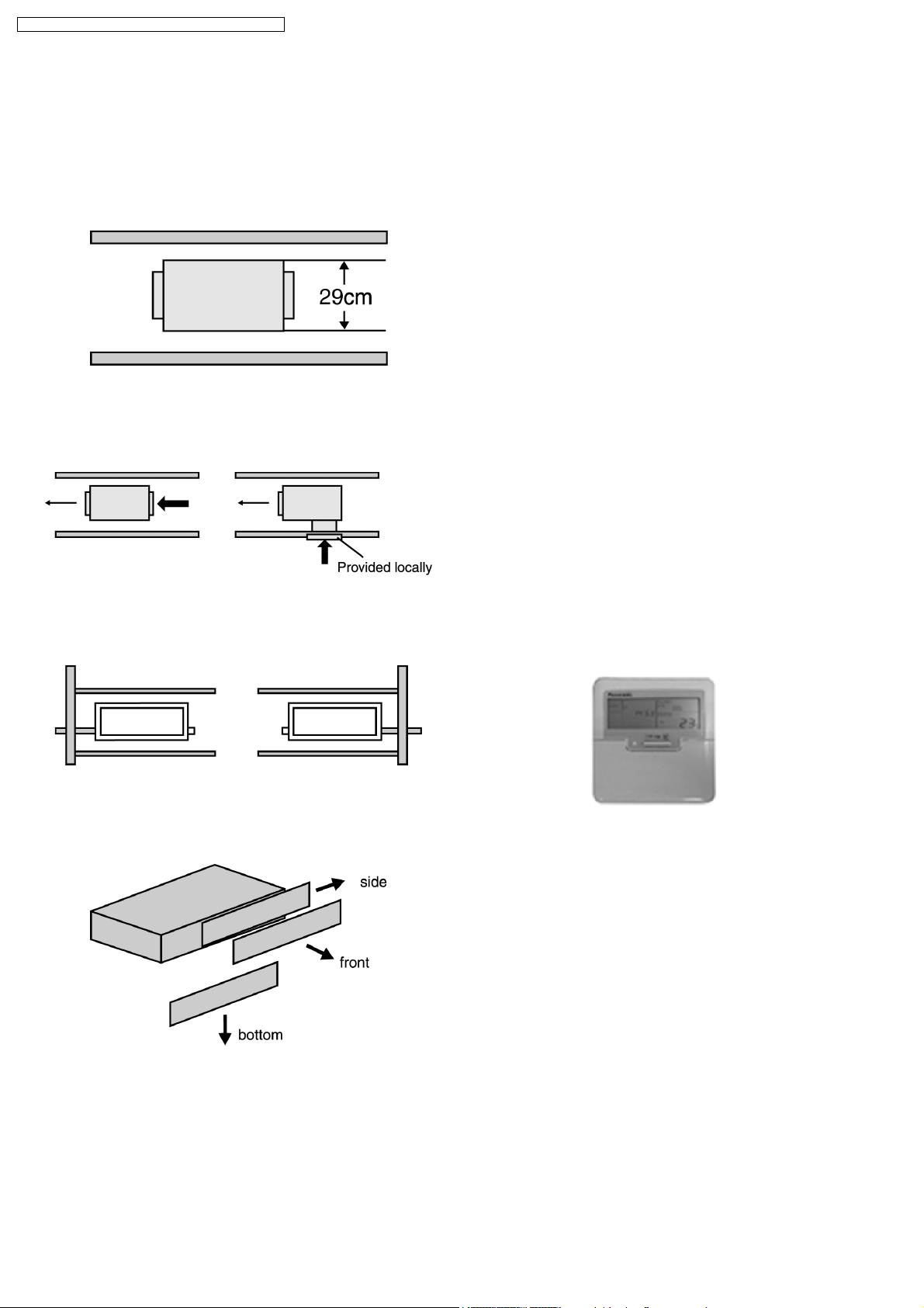
2.1.1. Compact design, height 29 cm
•
•
The height has been reduced to 29 cm, the equipment can
• •
be installed in limited spaces.
2.1.2. Versatile installation
•
•
The indoor unit is designed in order that air will also enter
• •
from below, for easier installation under differen t conditions.
2.1.5. Quiet operation
•
•
The sound level is as low as 41db (A) for 2.5 HP. The
• •
models is ideal for installation in offices, shop and houses
where quiet operation is important.
2.1.6. Auto fan mode operation (indoor
unit)
•
•
Auto fan mode is added to existing modes Hi, Me and Lo.
• •
It automatically adjusts the fan speed according to the
indoor temperature.
2.1.7. Dry mode function
•
•
Dry mode can make a comfortable indoor environment
• •
during wet season.
2.1.8. Automatic changeover function
(heat pump models)
•
•
The unit automatically switches between cooling and
• •
heating in accordance with operating load in order to
maintain a confortable indoor temperature.
2.1.9. Common design for Indoor unit
and Remote Control
•
•
The equipment has two drain outlets on the right and left
• •
side for adoption to the installation conditions in the
building.
2.1.3. Easy maintenance
•
•
Equipped with a filter as standard. The filter can be
• •
removed in three directions for easier maintenance.
•
•
The indoor unit and the wired remote control are design as
• •
a common specification between Cooling only and Heat
Pump models.
2.1.10. Wired Remote Control
•
•
The new design includes an easily-visible red pilot lamp.
• •
The power can be turned on and off at a single touch,
without opening the cover.
•
•
A built-in thermistor, allowing indoor temperature detection
• •
in accordance with indoor conditions by switching with main
unit thermistor.
•
•
Twin non-polar wires make installation work easy (10 m
• •
cable supplied as accessories).
2.1.4. Static pressure selection
•
•
The static pressure is selectable; 5mmAq or 7mmAq. The
• •
static pressure can be selected according to the condition
of the duct.
4
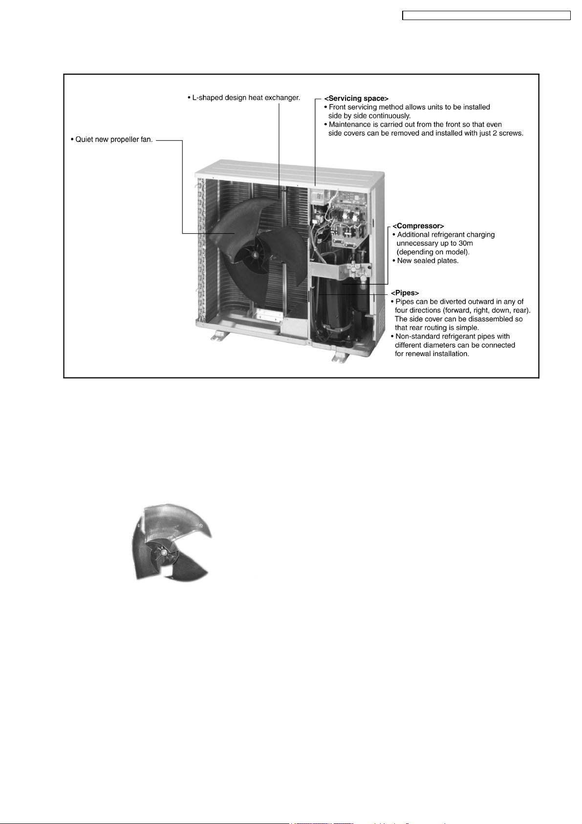
2.2. New low-noise outdoor units
CS-F24DD2E5 CU-L24DBE5 / CS-F28DD2E 5 CU-L28DBE 5 /
[Product features]
2.2.1. Low-noise design improves in
surrounding areas
1. The noise-suppressing winglet fan is a result of new
research into vane design theory. The unique curved shape
suppresses the generation of vortexes, thus reduces air
flow noise.
2. The adoption of double-orifice rings reduces air passage
resistance.
3. Strengthening of the noise insulation materials in the
compressor and the sealing-in of mechanical noise allows
vibration noise to be greatly enclosed and suppressed.
4. The heat exchanger has an L-shaped design to allow air to
flow more smoothly.
5. Noise is automatically reduced further during night time
operation with lower outdoor air temperatures.
2.2.2. Automatic restart function
When the electric power resumes after a power failure, the unit
will automatically restarts the operation in the pre-failure mode.
2.2.3. Low ambient cooling operation
Cooling operation is possible at outdoor temperature of -5°C.
5
CS-F24DD2E5 CU-L24DBE5 / CS-F28DD2E 5 CU-L28DBE 5 /
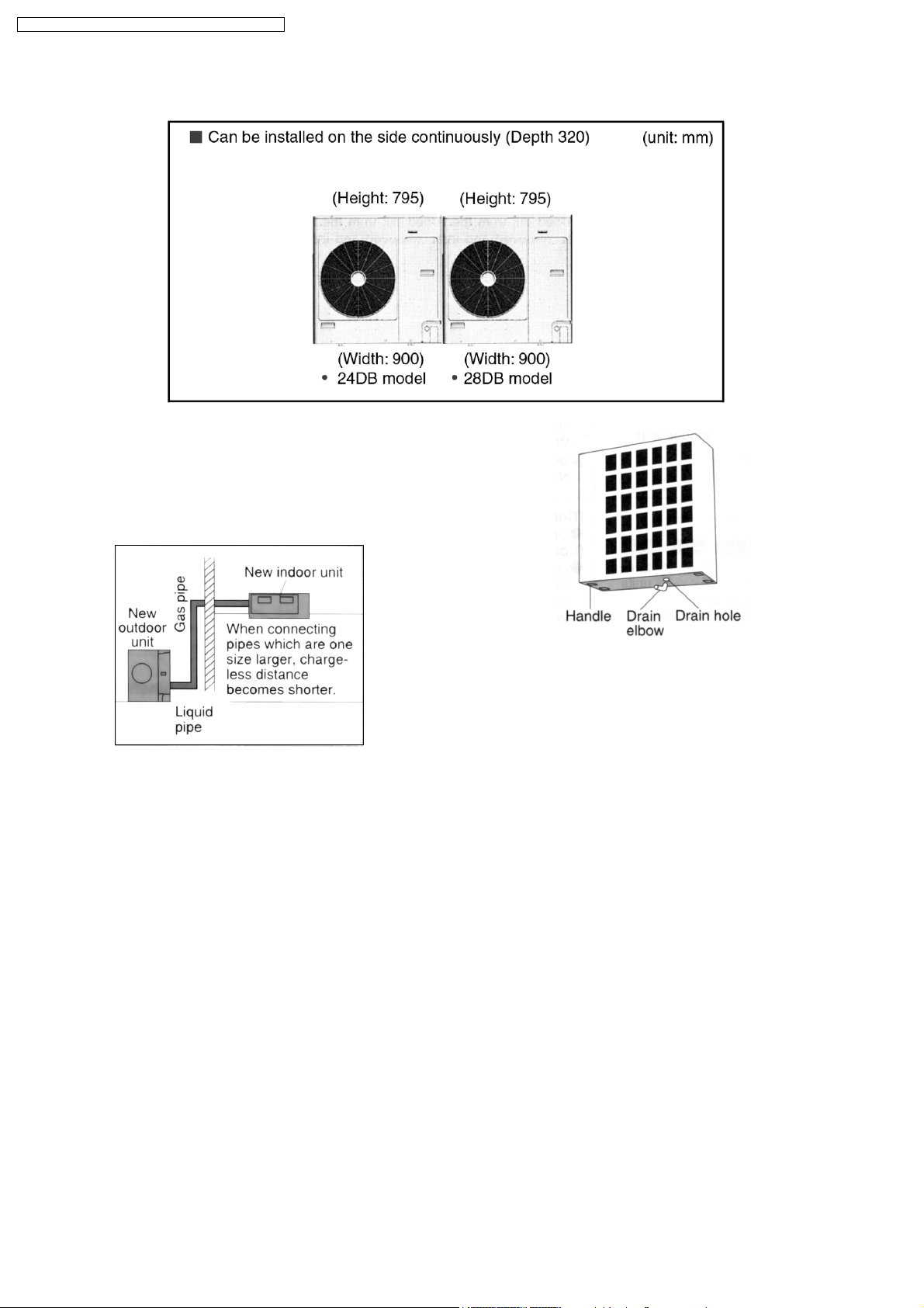
2.3. Greatly improved workability increases system renewal capability
2.3.1. Pipes that are one size larger can
also be connected for renewal
•
•
If renewing the system, existing refrigerant pipes can be
• •
utilized so that only the indoor units and outdoor units need
to be replaced.
•
•
For example, liquid and gas pipes from 10 years ago can be
• •
connected to current pipes with the same size for one size
larger. Effective utilization of materials reduces working
time and trouble. (Adaptor sockets are not supplied.)
2.3.2. Additional refrigerant charging
unnecessary for 30 m
•
•
All models do not require any additional charging of
• •
refrigerant for 30 m of pipe length. This makes installation
much easier.
2.3.3. Drain water dripping-prevention
structure
•
•
The base of the outdoor unit is provided with a single drain
• •
hole in order to prevent drain water from leaking out of the
unit. Body connecting a drain elbow and a discharge pipe,
water leakages can be prevented even when the unit is
installed against a wall.
2.3.4. Space saving design allows units
to be installed side by side
continuously
•
•
Servicing after installation can be carried out by removing
• •
the front covers.
2.3.5. Easy test operation
•
•
Test operation can be carried out for both indoor and
• •
outdoor units.
2.3.6. Long pipe design
•
•
Maximum piping length of 50 m.
• •
2.3.7. Internal pipe connection
•
•
Pipes are connected inside the units (inside the side
• •
covers), making the final appearance more attractive.
•
•
Pipes can be diverted outward in any of four directions
• •
(forward, right, down, rear).
•
•
Small liquid pipe diameters of 9.52mm, making installation
• •
work much easier.
6
CS-F24DD2E5 CU-L24DBE5 / CS-F28DD2E 5 CU-L28DBE 5 /
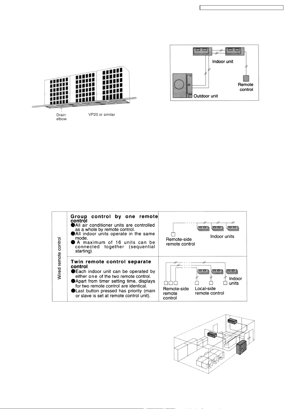
2.3.8. Centralized draining method
•
•
Even when multiple outdoor units are installed to a wall, the
• •
drain outlets can be concentrated into a single drain pipe.
This makes installation easier and also improve
appearance.
2.4. A brand-new control method
using the latest in technology
2.4.1. Power supply wiring is also easier
Power supply wiring and other wiring tasks can be carried out
more easily.
•
•
Twin non-polar wires used to connect indoor and outdoor
• •
units.
•
•
Adoption of connection error prevention circuits for drives
• •
wires and signal wires. If a connection error is made, the
relay does not operate and current does not flow to the
circuit boards.
2.4.2. Separate indoor/outdoor unit
power supplies
The power supply can be connected to (1) just the outdoor
units, or (2) to both indoor and outdoor units.
2.4.3. Automatic setting initialization
function (Remote control and
Indoor unit)
In accordance with the indoor and outdoor units connected and
the connection methods, conditions such as the configuration
(twin or triple format) and remote-control functions such as
cooling only or heat pump model are automatically detected
and set instantly.
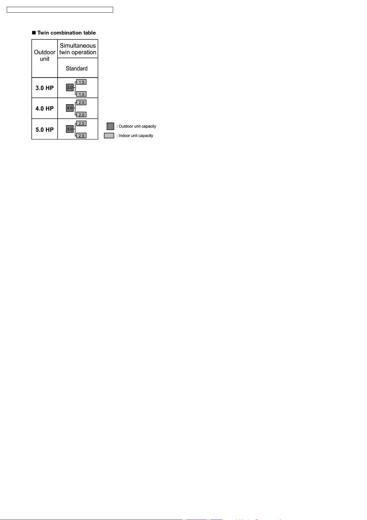
2.4.4. Group control equipment
2.4.5. Twin operation
•
•
Simultaneous air conditioning of wide spaces and corners is
• •
possible. Indoor units of different horsepowers and models
can even be used in combination.
•
•
Master unit and slave-units can be set automatically in twin
• •
systems. No address setting is necessary.
•
•
Multiple indoor units can be operated simultaneously with a
• •
single remote control. Note that individu al operation is not
possible.
7
CS-F24DD2E5 CU-L24DBE5 / CS-F28DD2E 5 CU-L28DBE 5 /
8

CS-F24DD2E5 CU-L24DBE5 / CS-F28DD2E 5 CU-L28DBE 5 /
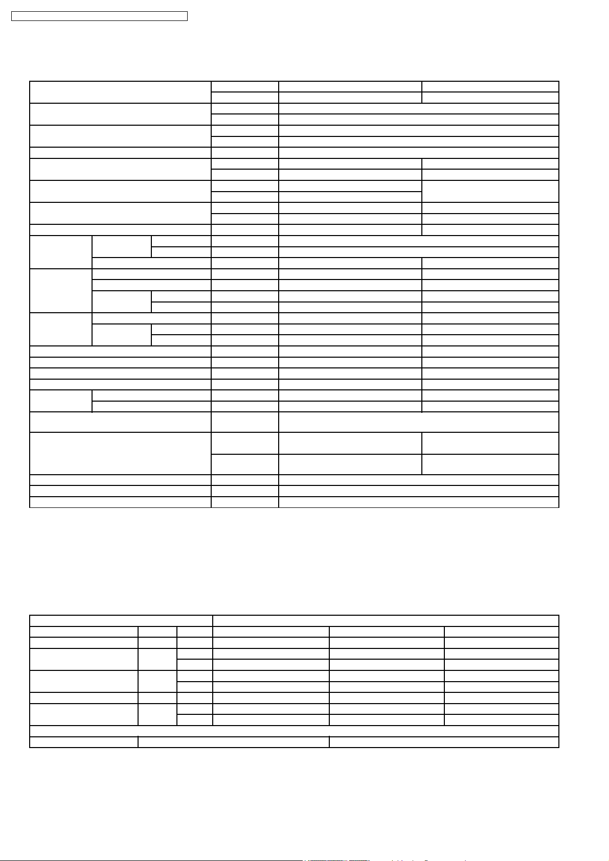
3 SPECIFICATION
3.1. CS-F24DD2E5 CU-L24DBE5
ITEM / MODEL Indoor Unit Outdoor Unit
Main Body CS-F24DD2E5 CU-L24DBE5
Cooling Capacity kW 6.3
BTU/h 21,500
Heating Capacity kW 7.1
BTU/h 24,200
Refrigerant Charge-less m 30
Standard Air Volume for High Speed m3/min Cooling; 19, Heating; 22 -
cfm Cooling; 671, Heating; 777 -
External Static Pressure Pa Hi 69 -
mmAq Hi 7.0
Outside Dimension (H x W x D) mm 290 x 1000 x 500 795 x 900 x 320
inch 11-13/32 x 39-5/16 x 19-21/32 31-5/16 x 35-7/16 x 12-19/32
Net Weight kg (lbs) 35 (78) 71 (158)
Piping
Connection
Compressor Type, Number of Set - Hermetic - 1 (Rotary), 1
Fan Type, Number of Set Sirocco fan Propeller fan-1
Air-heat Exchanger (Row x Stage x FPI) Slit-fin type (2 x 10 x 20) Louvre-fin type (2 x 36 x 19)
Refrigerant Control Capillary tube Refrigerant Oil (Charged) cm
Refrigerant (Charged) R410A kg (oz) - 2.13 (75)
Running
Adjustment
Safety Devices Internal protector for compressor, Internal thermostat for fan motor,
Noise Level dB (A) Cooling : Hi 45 Lo 41 Cooling 47, Heating 49
Moisture Removal L/h (Pt/h) EER W/W 3.01
COP W/W 3.41
Refrigerant Gas mm (inch) O.D Ø 15.88 (5/8) Flared Type
Liquid mm (inch) O.D Ø 9.53 (3/8) Flared Type
Drain mm Female screw RC1 (PT1) I.DØ20x1
Starting Method - Direct on-line starting
Motor Type - 4-pole single phase brushless motor
Rated Output kW - 1.8
Motor Type 4-pole single phase induction motor 6-pole single phase induction motor
Rated Output kW 0.135 0.07
3
Control Switch Wired Remote Control Room Temperature Thermostat -
Crankcase heater, High pressure switch, Current transformer
Heating : Hi 43 Lo 39
Power level dB Cooling : Hi 61 Lo 57
Heating : Hi 59 Lo 55
- FV50S (800)
Cooling 63, Heating 65
1. Cooling capacities are based on indoor temperature of 27°C D.B. (80.6°F D.B.), 19.0°C W.B. (66.2°F W.B.) and outdoor air
temperature of 35°C D.B. (95°F D.B.), 24°C W.B. (75.2°F W.B.)
2. Heating capacities are based on indoor temperature 20°C D.B. (68°F D.B.) and outdoor air temperature of 7°C D.B. (44.6°F
D.B.), 6°C W.B. (42.8°F W.B.)
ELECTRICAL DATA (50 Hz)
ITEM / MODEL Condition by JIS-B8615
Volts V 220 230 240
Phase Single Single Single
Power Consumption kW Cool 2.09 2.09 2.09
Heat 2.08 2.08 2.08
Running Current A Cool 9.9 9.5 9.2
Heat 9.9 9.5 9.2
Starting Current A 9.9 9.5 9.2
Power Factor % Cool 96 96 95
Heat 96 95 94
*Power Factor means total figure of compressor, indoor fan motor and outdoor fan motor.
Panasonic Power source AC, 1~220V, 230V, 240V 50Hz
9
CS-F24DD2E5 CU-L24DBE5 / CS-F28DD2E 5 CU-L28DBE 5 /
3.2. CS-F28DD2E5 CU-L28DBE5
ITEM / MODEL Indoor Unit Outdoor Unit
Main Body CS-F28DD2E5 CU-L28DBE5
Cooling Capacity kW 7.1
BTU/h 24,200
Heating Capacity kW 8.0
BTU/h 27,300
Refrigerant Charge-less m 30
Standard Air Volume for High Speed m3/min Cooling; 19, Heating; 22 -
cfm Cooling; 671, Heating; 777 -
External Static Pressure Pa Hi 69 -
mmAq Hi 7.0
Outside Dimension (H x W x D) mm 290 x 1000 x 500 795 x 900 x 320
inch 11-13/32 x 39-5/16 x 19-21/32 31-5/16 x 35-7/16 x 12-19/32
Net Weight kg (lbs) 35 (78) 71 (158)
Piping
Connection
Compressor Type, Number of Set - Hermetic - 1 (Rotary), 1
Fan Type, Number of Set Sirocco Fan Propeller fan-1
Air-heat Exchanger (Row x Stage x FPI) Slit-fin type (2 x 10 x 20) Louvre-fin type (2 x 36 x 19)
Refrigerant Control Capillary tube Refrigerant Oil (Charged) cm
Refrigerant (Charged) R410A kg (oz) - 2.35 (83)
Running
Adjustment
Safety Devices Internal protector for compressor, Internal thermostat for fan motor,
Noise Level dB (A) Cooling : Hi 45 Lo 41 Cooling 48, Heating 50
Moisture Removal L/h (Pt/h) EER W/W 3.01
COP W/W 3.42
Refrigerant Gas mm (inch) O.D Ø 15.88 (5/8) Flared Type
Liquid mm (inch) O.D Ø 9.53 (3/8) Flared Type
Drain mm Female screw RC1 (PT1) I.D Ø 20 x 1
Starting Method - Direct on-line starting
Motor Type - 4-pole single phase brushless motor
Rated Output kW - 2.0
Motor Type 4-pole single phase induction motor 6-pole single phase induction motor
Rated Output kW 0.135 0.07
3
Control Switch Wired Remote Control Room Temperature Thermostat -
Crankcase heater, High pressure switch, Current transformer
Heating : Hi 43 Lo 39
Power level dB Cooling : Hi 61 Lo 57
Heating : Hi 59 Lo 55
- FV50S (800)
Cooling 64, Heating 66
1. Cooling capacities are based on indoor temperature of 27°C D.B. (80.6°F D.B.), 19.0°C W.B. (66.2°F W.B.) and outdoor air
temperature of 35°C D.B. (95°F D.B.), 24°C W.B. (75.2°F W.B.)
2. Heating capacities are based on indoor temperature of 20°C D.B. (68°F D.B.) and outdoor air temperature of 7°C D.B. (44.6°F
D.B.), 6°C W.B. (42.8°F W.B.)
ELECTRICAL DATA (50 Hz)
ITEM / MODEL Condition by JIS-B8615
Volts V 220 230 240
Phase Single Single Single
Power Consumption kW Cool 2.36 2.36 2.36
Heat 2.34 2.34 2.34
Running Current A Cool 11.2 10.7 10.3
Heat 11.1 10.6 10.2
Starting Current A 11.1 10.6 10.2
Power Factor % Cool 96 96 95
Heat 96 96 96
*Power Factor means total figure of compressor, indoor fan motor and outdoor fan motor.
Panasonic Power source AC, 1~220V, 230V, 240V 50Hz
10
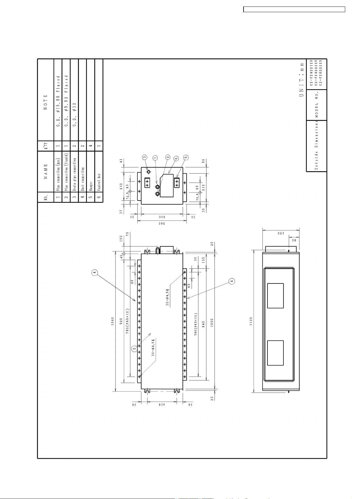
4 DIMENSIONS
4.1. CS-F24DD2E5 CS-F28DD2E5
CS-F24DD2E5 CU-L24DBE5 / CS-F28DD2E 5 CU-L28DBE 5 /
11

CS-F24DD2E5 CU-L24DBE5 / CS-F28DD2E 5 CU-L28DBE 5 /
4.2. CU-L24DBE5 CU-L28DBE5
12
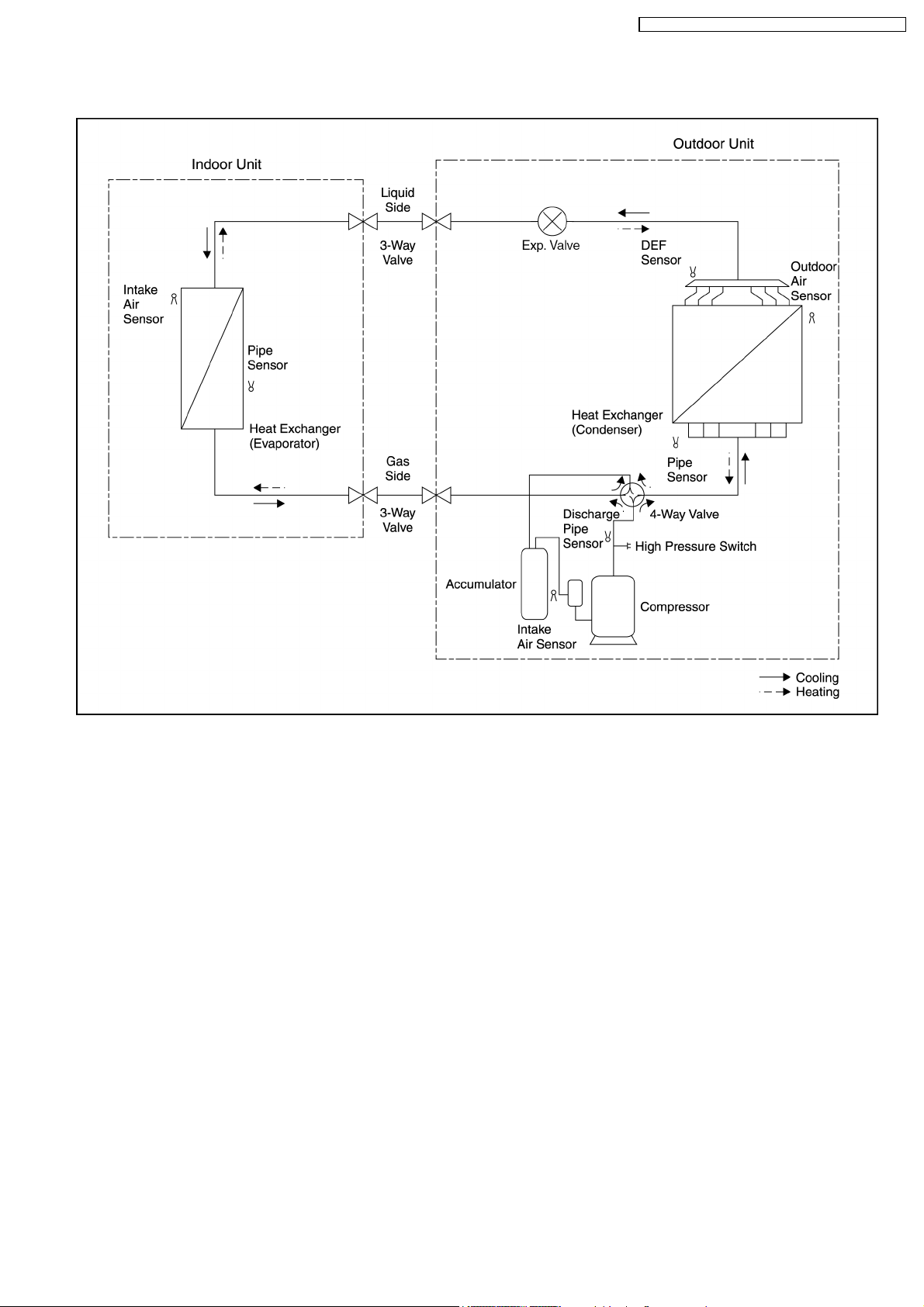
5 REFRIGERATION CYCLE
CS-F24DD2E5 CU-L24DBE5 / CS-F28DD2E 5 CU-L28DBE 5 /
13
CS-F24DD2E5 CU-L24DBE5 / CS-F28DD2E 5 CU-L28DBE 5 /
6 BLOCK DIAGRAM
6.1. CS-F24DD2E5 CS-F28DD2E5
14
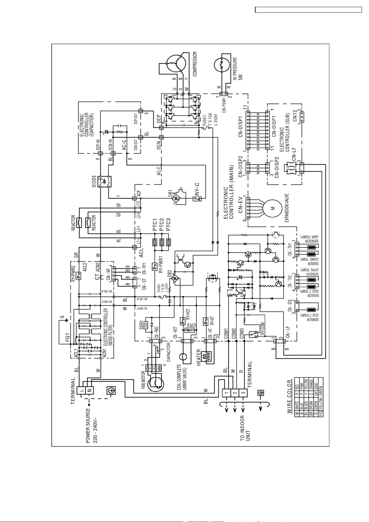
6.2. CU-L24DBE5 CU-L28DBE5
CS-F24DD2E5 CU-L24DBE5 / CS-F28DD2E 5 CU-L28DBE 5 /
15
CS-F24DD2E5 CU-L24DBE5 / CS-F28DD2E 5 CU-L28DBE 5 /
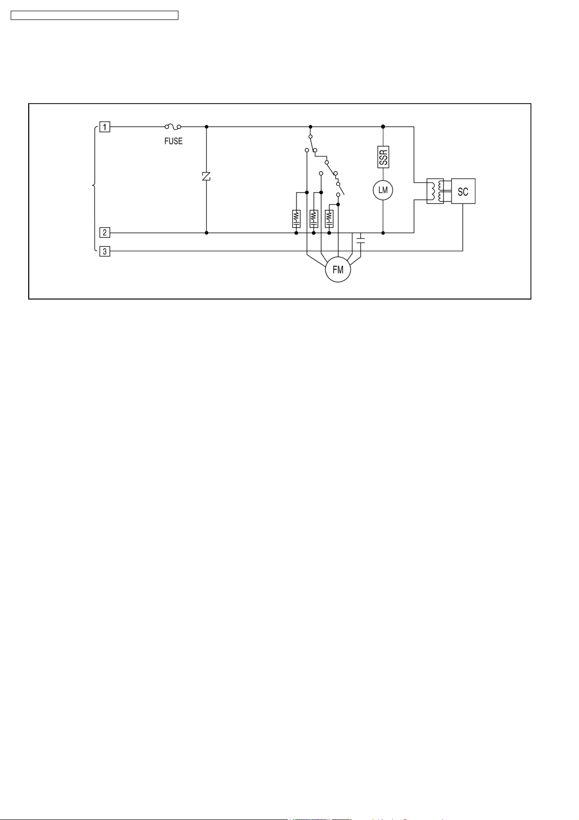
7 WIRING DIAGRAM
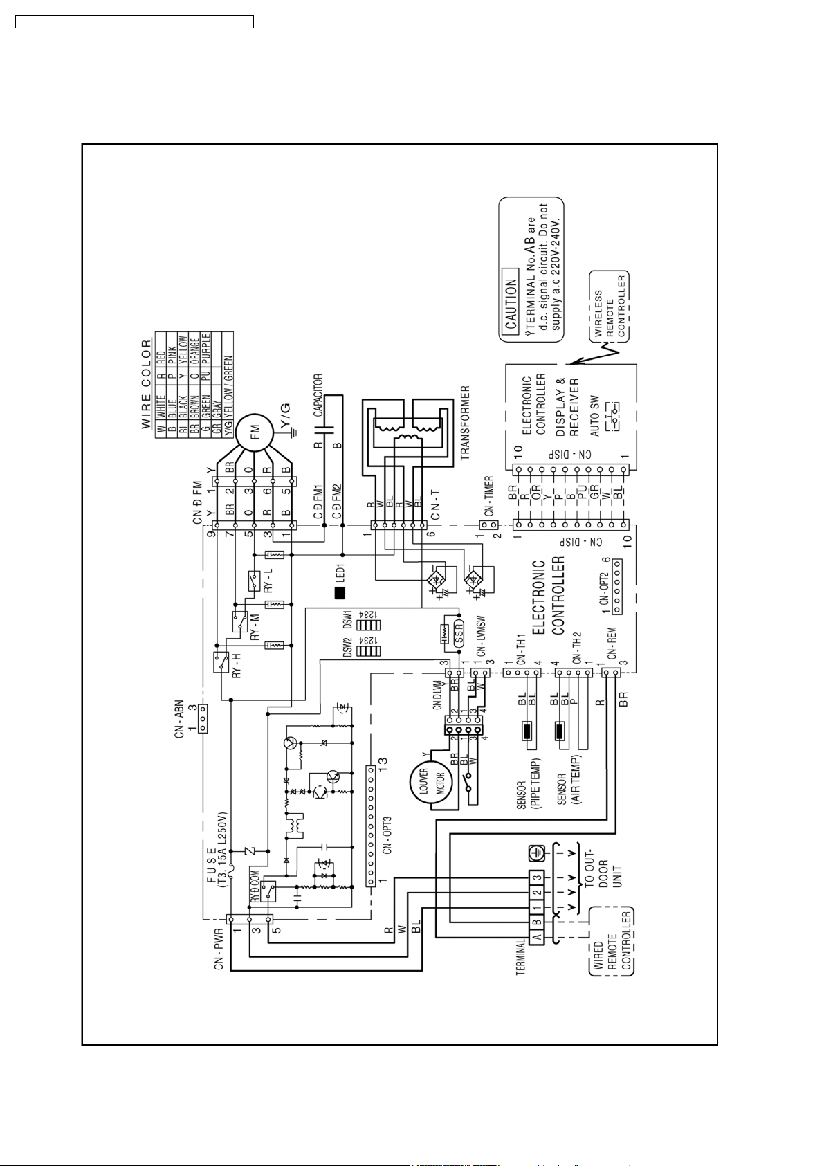
7.1. CS-F24DD2E5 CS-F28DD2E5
16
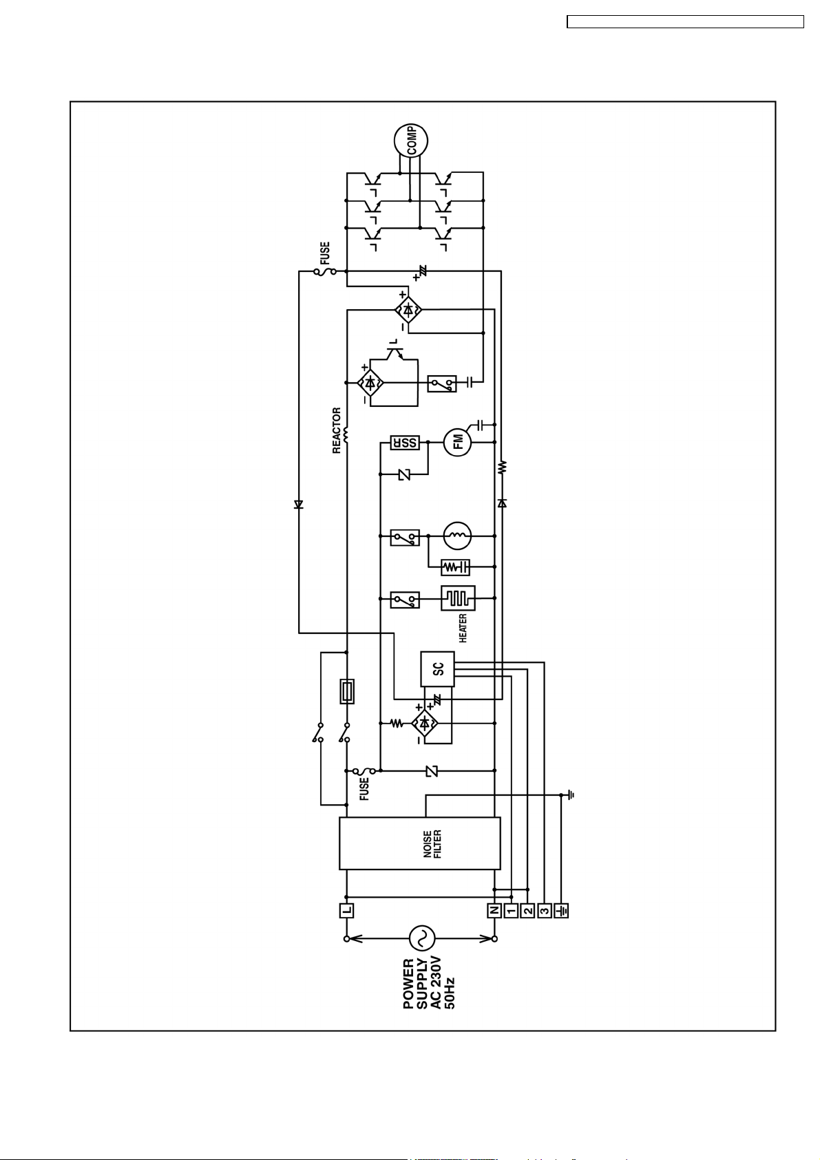
7.2. CU-L24DBE5 CU-L28DBE5
CS-F24DD2E5 CU-L24DBE5 / CS-F28DD2E 5 CU-L28DBE 5 /
17
CS-F24DD2E5 CU-L24DBE5 / CS-F28DD2E 5 CU-L28DBE 5 /
8 OPERATION DETAILS
8.1. Wired Remote Control (Optional part)
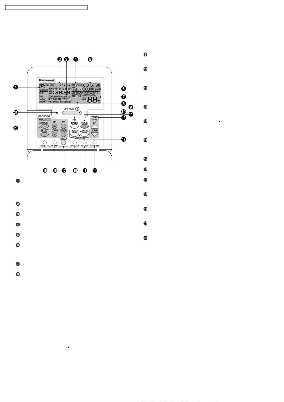
8.1.1. Name and function of each part
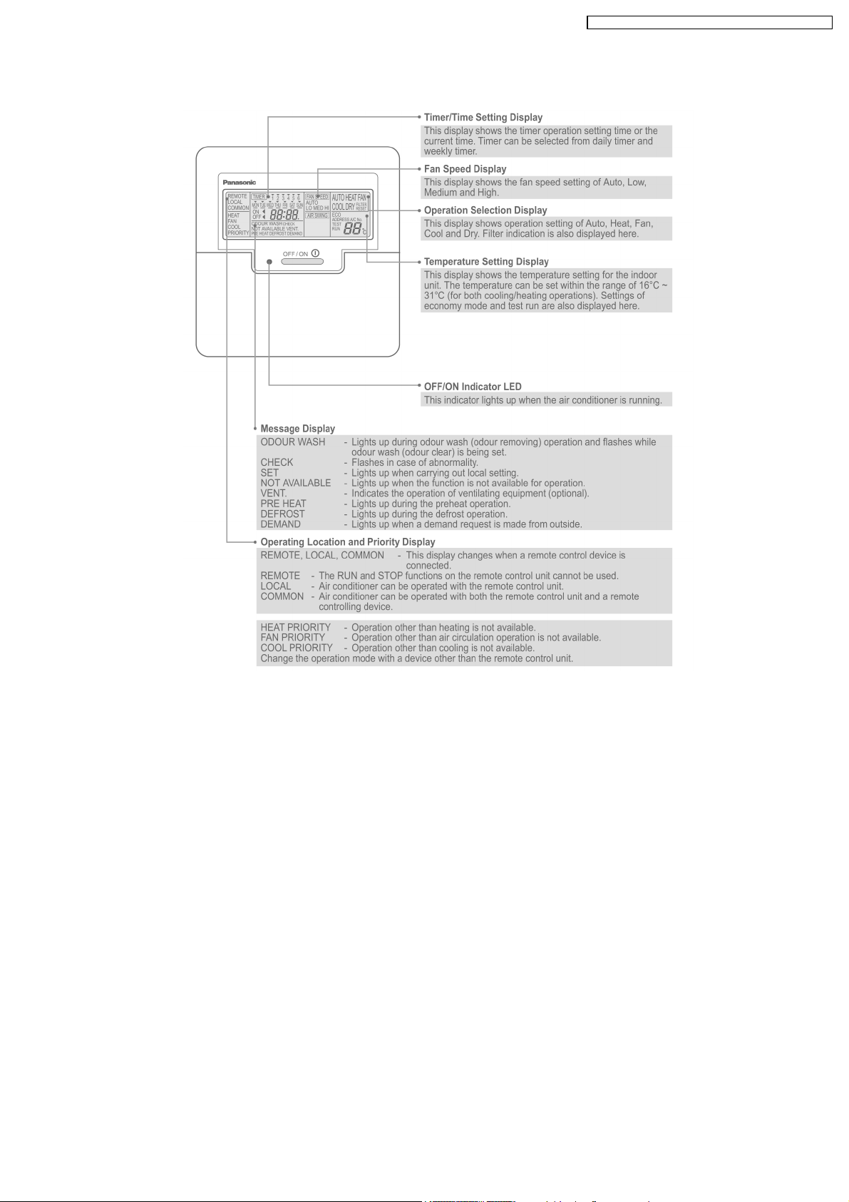
REMOTE
The OFF/ON button cannot be used.
LOCAL
All wired remote control buttons can be used.
Time/time setting display
Check display
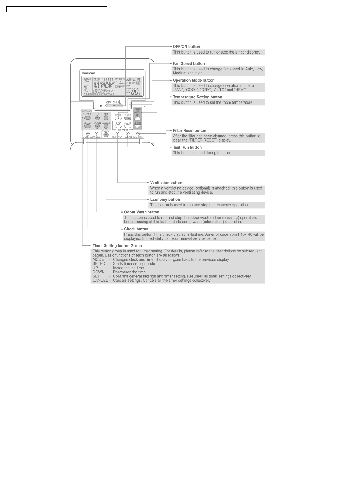
OFF/ON button
Used to start and stop the operation.
FAN SPEED button
Used to select the fan speed of high (HI), medium (MED), low
(LO) or auto (AUTO).
MODE button
Used to select the operation of AUTO, HEAT, FAN, COOL, or
DRY.
TEMP (UP/DOWN) buttons
Used to select the desired temperature.
AIR SWING (AUTO/MANUAL) buttons
Used to determined the air swing condition, either auto or
manual.
FILTER RESET button
Press to reset the “FILTER RESET” display after washing the
filter.
TEST RUN button*
VENTILATION button*
ECONOMY operation button
Provides Energy saving function
ODOUR WASH button
Provides deodorizing function.
CHECK button
Press this button if the check display is flashing.
Fan speed display
Operation mode selection display
FILTER RESET display
(Appears after the cumulative running time reaches
approximately 2,500 hours of operation.)
Temperature setting display (16°C - 31°C)
Airflow direction setting display
TIMER/CLOCK SET buttons
Used to set the timer operation and the current time.
Operation indicator
Lights up when the unit in operation.
NOTES
•
•
Ensure that the correct button is pressed as simultaneous pressing of the multiple buttons will not make the setting correct.
• •
•
•
The illustration above is for explanatory purposes only. The appearance will be different during actual operation.
• •
•
•
Do not operate the remote control with wet hands. Otherwise, electric shock or malfunction may occur.
• •
•
•
Do not press the remote control buttons with sharp object as this may damage the remote control.
• •
•
•
Buttons marked with * are not needed for normal operation. If one of these buttons is pressed by mistake, press the same
• •
button once more to cancel the operation.
•
•
When the power resumed after power failure, the unit will restart automatically with all the previous settings preserved by
• •
the memory function. (Auto restart function)
•
•
Buttons marked with
• •
are not available for operation. If one of these buttons is pressed function will not be available.
18
8.1.2. Remote Control - Display
CS-F24DD2E5 CU-L24DBE5 / CS-F28DD2E 5 CU-L28DBE 5 /
19
CS-F24DD2E5 CU-L24DBE5 / CS-F28DD2E 5 CU-L28DBE 5 /
8.1.3. Remote Control - Panel
20
CS-F24DD2E5 CU-L24DBE5 / CS-F28DD2E 5 CU-L28DBE 5 /
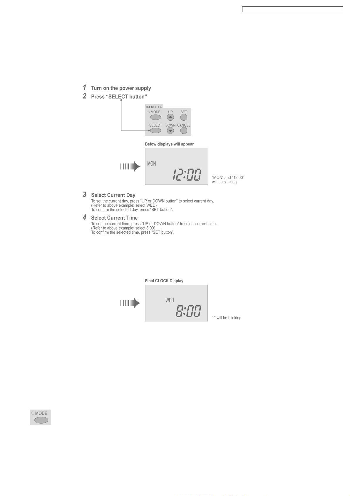
8.1.4. Setting Current Time
•
•
The current time needs to be set when you turn on the power for the first time or after a long time has elapsed since the power
• •
was last turned on.
•
•
The current time becomes the standard time for all the Timer operations.
• •
•
•
Set the current time and day accurately.
• •
•
•
Example : Current Day is Wednesday and Current Time is 8:00.
• •
Note:
•
•
Press “UP button” to increase or “DOWN button” to decrease (interval 1 minute) or hold the button to change the time faster.
• •
•
•
If the “UP or DOWN button” is not pressed for 30 seconds during the day or time setting or if the “SELECT button” is
• •
pressed, the setting at that moment is confirmed and setting will end.
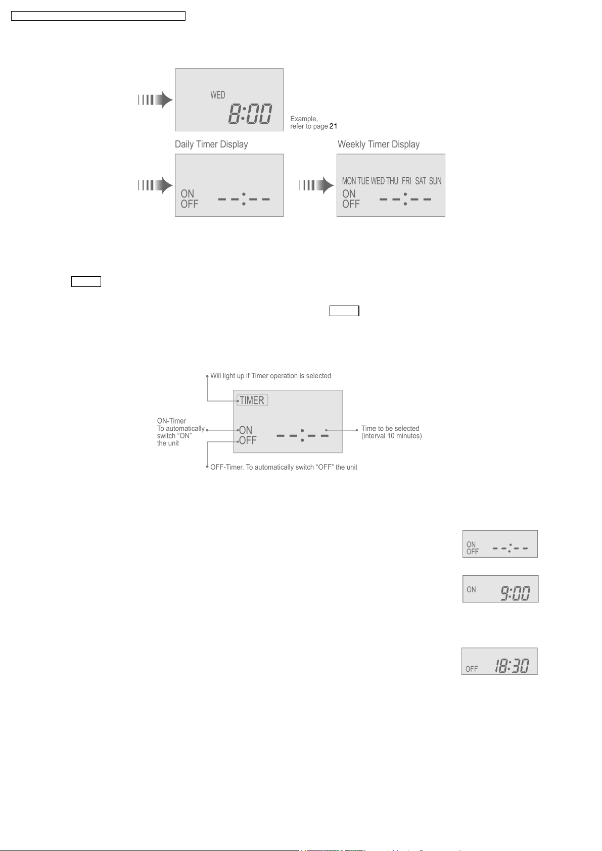
8.1.5. How To Select The Timer
•
•
2 types of Timer mode can be selected on the remote control.
• •
−
−
Daily Timer
− −
−
−
Weekly Timer
− −
•
•
These timers cannot be operated simultaneously.
• •
•
•
Select one of these Timers for your convenience.
• •
How to Change the Display
•
•
Press once to change the display from CLOCK to Timer or vice-versa.
• •
•
•
Press more than 3 seconds to change the display from Daily Timer to Weekly Timer or vice-versa.
• •
21
CS-F24DD2E5 CU-L24DBE5 / CS-F28DD2E 5 CU-L28DBE 5 /
CLOCK Display (To set current Day and Time)
Note:
•
•
The above display is shown if no valid timer setting is made.
• •
•
•
If valid timer setting is made.
• •
−
−
Timer
− −
−
−
If you want to check the current time and day, press “MODE button” once.
− −
and setting will be displayed.
(However, after a few seconds, the display will change back to Timer
and the setting)
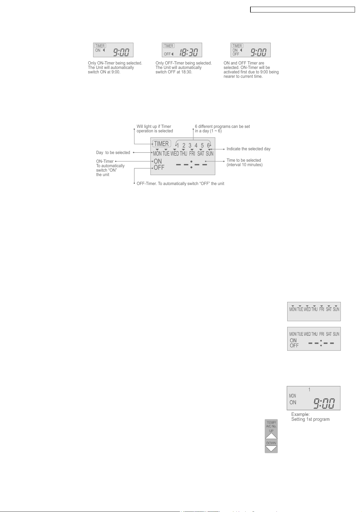
8.1.6. Daily Timer Setting
•
•
Display
• •
•
•
How to Set Daily Timer
• •
−
−
You can set only “ON” or only “OFF” or “ON” and “OFF” in a day.
− −
1. Change Display
Press “MODE button” to change the display to daily timer.
2. ON-Timer, OFF-Timer and select Time
Press “SELECT button”; ON-Timer setting will be displayed.
Press “UP or DOWN button” to select the desired time, (Example: ON 9:00), then press “SET button” to confirm
the selected desired time.
Or press “CANCEL button” if you do not want any setting for ON-Timer.
Then OFF-Timer setting will be displayed.
Press “UP or DOWN button” to select the desired time, (Example: OFF 18:30), then press “SET button” to
confirm the selected desired time.
Or press “CANCEL button” if you do not want any setting for OFF-Timer.
Note:
•
•
The setting timer will be activated everyday.
• •
•
•
Timer nearer to the current time will be activated first.
• •
22
Final Display of Daily Timer:
8.1.7. Weekly Timer Setting
•
•
Display
• •
CS-F24DD2E5 CU-L24DBE5 / CS-F28DD2E 5 CU-L28DBE 5 /
•
•
How to Set Weekly Timer
• •
−
−
You can set the Timer for 1 week (Monday to Sunday ) with 6 programs per day.
− −
−
−
ON-Timer can be set together with your desired temperature. However, this temperature will be used continuously.
− −
−
−
Cannot set 2 programs with same time setting in a day.
− −
−
−
You also may select Collective - many days with same time setting or Individual
− −
−
−
single/one day setting.
− −
1. Change Display
Press “MODE button” to change the display to weekly timer.
2. Select Day (please refer to next page for example of setting)
You may select Collective or Individual day setting.
•
•
Collective day setting.
• •
Press “SELECT button”: display will show day selection setting.
Press “UP or DOWN button” to select the day. Then press “SET button” to delete triangle mark
(deselect) or add triangle mark (select).
(Triangle mark on top of each day indicates the day to be selected).
Repeat these steps if you want to deselect or select many days.
To confirm the selected days, press the “SELECT button”.
•
•
Individual day setting.
• •
Press “UP or DOWN button” to select the day.
Then press “SELECT button”.
3. Select Time (please refer to next page for example of setting)
For 1st program setting.
Press “UP or DOWN button” to select ON or OFF.
Then press “SET button” to confirm.
Press “UP or DOWN button” again to select the desired time.
(If you want to set them together with your desired temperature, press “TEMP UP/DOWN button” to
select the temperature).
Then press “SET button” to confirm.
Or press “CANCEL button” if you do not want to set any time.
For 2nd ~ 6th program you may refer to the above step.
23
CS-F24DD2E5 CU-L24DBE5 / CS-F28DD2E 5 CU-L28DBE 5 /
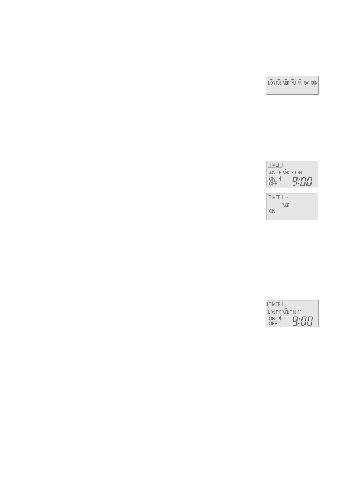
For example , if you want to set:
A - Monday to Friday: Same time, 1st program ON 9:00 & 2nd program OFF 16:00.
B - Only Wednesday: Additional 3rd program OFF 12:30 & 4th program ON 13:30.
C - Only Saturday: 1st program ON 10:00 with 20°C & 2nd program OFF 14:00.
D - Sunday: Holiday. No need to set any Timer.
•
•
To set A (Monday to Friday - Collective day setting)
• •
Press “SELECT button”
To select Monday to Friday, deselect Saturday and Sunday by pressing “UP or DOWN button” to Saturday, press
“SET button” (triangle mark on top of Saturday will disappear)
Follow the same step to deselect Sunday.
Ensure triangle mark appears on top of Monday ~ Friday.
−
−
To confirm the selected days, press “SELECT button”.
− −
To set the time, please refer to step 3. Select time at page 23.
−
−
1st program - select ON and desired time to 9:00.
− −
2nd program - select OFF and desired time to 16:00.
3rd ~ 6th program - press “CANCEL button”.
•
•
To set B (Wednesday - Individual day setting)
• •
−
−
Press “UP or DOWN button” to select WED (Wednesday).
− −
Then press “SELECT button”.
To set the time, please refer to step 3. Select time at page 23.
−
−
1st program - press “SET button” twice (confirm ON and 9:00)
− −
2nd program - also press “SET button” twice. (Confirm OFF and 16:00)
3rd program - select OFF and desired time to 12:30
4th program - select ON and desired time to 13:30
5th ~6th program - press “CANCEL button”
•
•
To set C (Saturday - Individual day setting)
• •
−
−
Follow the same step as above.
− −
To set the time, please refer to step 3. Select time at page 23.
−
−
1st program - select ON, desired time to 10:00 and desired temperature to 20°C.
− −
2nd program - select OFF and desired time to 14:00.
3rd ~ 6th program - press “CANCEL button”.
−
−
Final Display for Weekly timer may show as:
− −
(Display is showing, 9:00 ON - Timer on Wednesday will be activated next because it is nearest the current
day/time.)
Note:
•
•
Timer that has setting nearest to current time and day will be activated first.
• •
•
•
To check the setting timer, press “SELECT button”, then “UP or DOWN button” to select day. The display will show each
• •
program for the selected day.
•
•
To reset the setting for all, press “SELECT button”, then ensure all day setting with triangle mark. Then press “CANCEL
• •
button” for all the programs.
24
CS-F24DD2E5 CU-L24DBE5 / CS-F28DD2E 5 CU-L28DBE 5 /
9 OPERATION CONTROL
Description of basic control functions
9.1. Operation Mode
1. Thermostat control
2. Depend on differences between room temperature and setting temperature, Compressor running frequency will be decided and
start operation.
Temperature differences become same as below table, then thermostat is off.
Temperature Differences
Unit: °C
Indoor type Cassette Ceiling Duct D2 Duct D3
Cool mode -1.5 -1.5 -2.0 -2.0
Dry mode -2.5 -2.5 -3.0 -3.0
Heat mode 3.5 2.5 2.5 2.5
3. Select indoor temperature thermostat
When connected to wired remote controller, either indoor unit thermostat or remote controller thermostat is available, using
remote control setting.
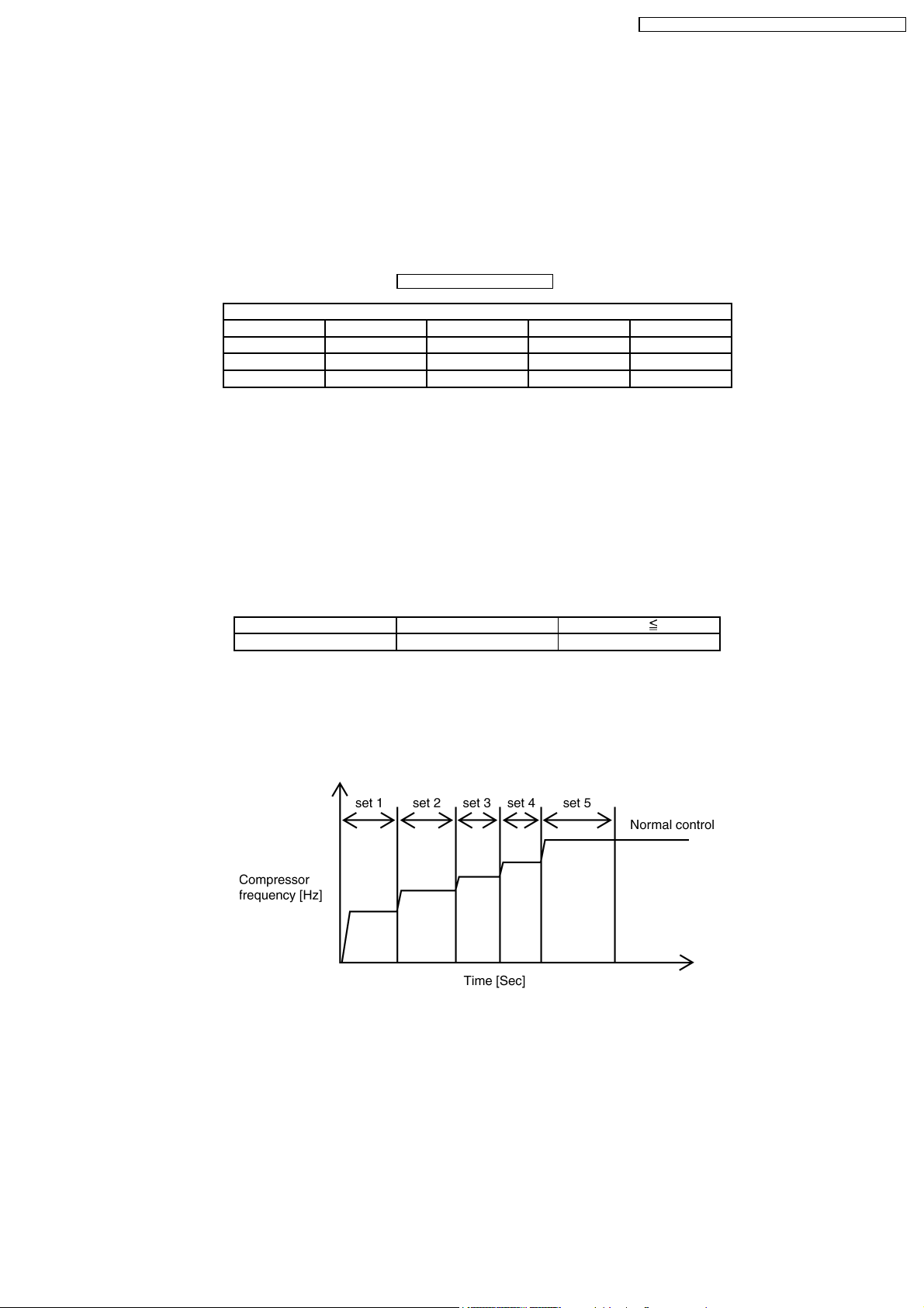
9.2. Compressor Start Control
•
•
When the compressor start, compressor frequency will be fixed at lower level for certain time, to follow the below table, due to
• •
avoid the compressor oil discharge.
•
•
Judging from compressor discharge temperature, decide the start condition to select either cool start control, or warm start
• •
control.
Discharge temp. [°C] >15°C 15°C
Start control Cool start Warm start
Warm start : set 1→*set 5→normal control
Cool start : set 1→set 2→set 3→set 4→*set 5→normal control
•
•
Note
• •
−
−
Frequency at *set 5 = frequency calculated by normal control
− −
−
−
In case of frequency at set n excess the frequency at set 5 in cool condition, skip from set n to set 4 and transfer to set 5.
− −
9.3. Cooling Operation
9.3.1. Cool indoor fan control
•
•
Fan speed manual
• •
Common control for unit using DC motor / unit using AC motor.
Operation start at hi speed, or medium speed, or low speed set by remote control.
•
•
Fan speed auto
• •
When operation start, or shifting to thermostat ON condition from thermostat OFF condition, odour cut operation (refer odour
cut operation page for detail), after thermostat ON condition, indoor fan operate as below control.
25
CS-F24DD2E5 CU-L24DBE5 / CS-F28DD2E 5 CU-L28DBE 5 /
−
−
Unit using DC motor
− −
As follow the below figure, fan speed changing operation (program air).
(rpm center B and
−
−
Unit using AC motor
− −
is differen t if capacity rank is different)
When 1st thermostat on condition from operation start, fan speed is hi (same as manual fan speed), after 2nd thermostat
on condition, fan speed change to medium speed (same as manual medium fan speed).
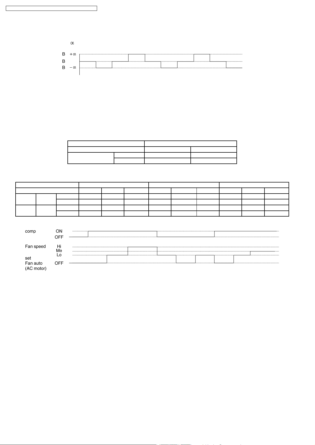
9.3.2. Odour cut control
•
•
When cool or dry mode operation start, select odour cut mode or fan auto mode, by remote control, operation start at odour
• •
wash mode when compressor start or shift to thermostat on from thermostat off.
•
•
Odour cut operation is under below condition.
• •
Operation mode Cool or dry mode
Odour wash setting Setting No setting
Fan setting Auto Odour cut Odour cut
Manual Odour cut -
•
•
Odour cut operation is to remove the odour generated at indoor heat exchanger to use the drain water come out from indoor
• •
heat exchanger.
Thermo & comp ON/OFF Thermostat ON & comp ON Thermostat ON Thermostat ON & comp ON
Time 40 [Sec] 50 [Sec] - 20 [Sec] 120 [Sec] 20 [Sec] 40 [Sec] 50 [Sec] -
Cool Auto DC motor OFF SSLo Program air SSLo OFF SSLo OFF SSLo Program air
AC motor OFF Lo Hi Lo OFF Lo OFF Lo Me
Dry Auto DC motor OFF SSLo SLo SSLo OFF SSLo OFF SSLo SLo
AC motor OFF Lo Lo Lo OFF Lo OFF Lo Lo
9.3.3. Cool powerful operation
•
•
When cool or dry mode operation start, temperature differences between room temperature and setting temperature is more
• •
than 5 K, setting temperature shift to 2 K down.
•
•
(But when temperature after shifting is less than 16°C, setting temperature is 16°C = no change)
• •
•
•
Micro computer judge that required indoor load is bigger than calculation base from temperature differences between room
• •
temperature and setting temperature, then increase the compressor frequency compared to normal to cool down indoor side
immediately.
•
•
Those kind of operation complete after 30 minutes when cool mode operation start.
• •
26
CS-F24DD2E5 CU-L24DBE5 / CS-F28DD2E 5 CU-L28DBE 5 /
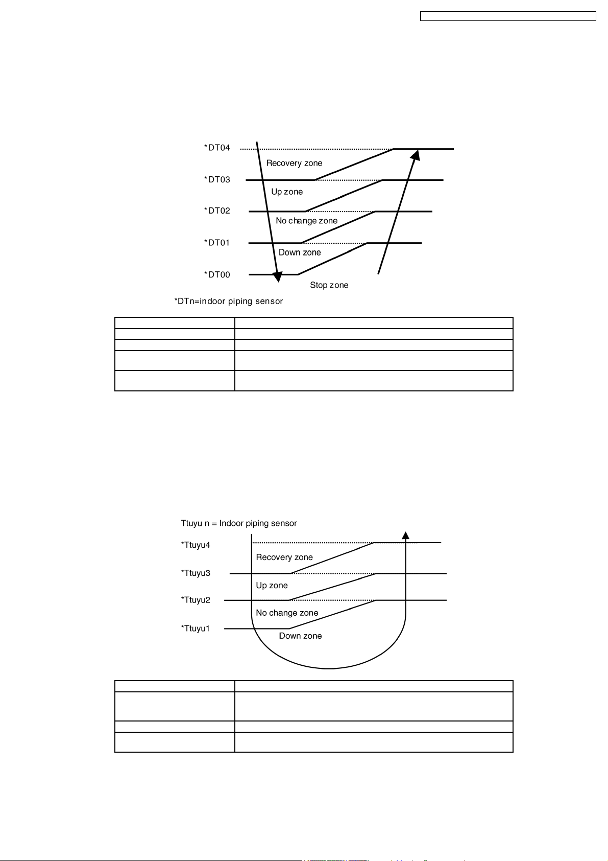
9.3.4. Freezing prevention control
•
•
During cool or dry mode operation, if indoor evaporator temperature is going down, freezing prevention control is operated.
• •
•
•
Detail of Freezing prevention control is as follows;
• •
Indoor evaporator temperature area is divided into 5 zones, which consist of stop zone, down zone, no change zone, up zone,
and recovery zone. When indoor evaporator temperature is going into each zone, compressor frequency change by following
the below table.
Recovery zone Release freezing prevention operation
Up zone Fan motor speed step up
No change zone Operation no change
Down zone Reduce the compressor frequency
Stop zone If continue for 6 min, compressor stop
(check for 3 min, max 3 times)
(for 3 min after stop, compressor can be started due to restart delay control)
9.3.5. Dew form prevention control
•
•
During cool or dry operation, if outdoor temperature is less than 30°C, and indoor fan speed is low or auto setting, indoor heat
• •
exchanger temperature become lower, dew form prevention control start to prevention dew form at indoor discharge grill.
•
•
Indoor evaporator temperature area is divided into 4 zones, which consist of, down zone, no change zone, up zone, and
• •
recovery zone.
•
•
When indoor evaporator temperature is going into each zone, change compressor frequency and louver angle by following the
• •
below table.
Recovery zone Release dew form prevention operation
Up zone Fix the indoor louver angle
No change zone Continue check the indoor heat excahnger temperature
Down zone Reduce the compressor frequency
Cassette type : fix the manual 3rd position
Ceiling type : fix the manual 2nd position
(check for 3 min, max 3 times)
27
CS-F24DD2E5 CU-L24DBE5 / CS-F28DD2E 5 CU-L28DBE 5 /
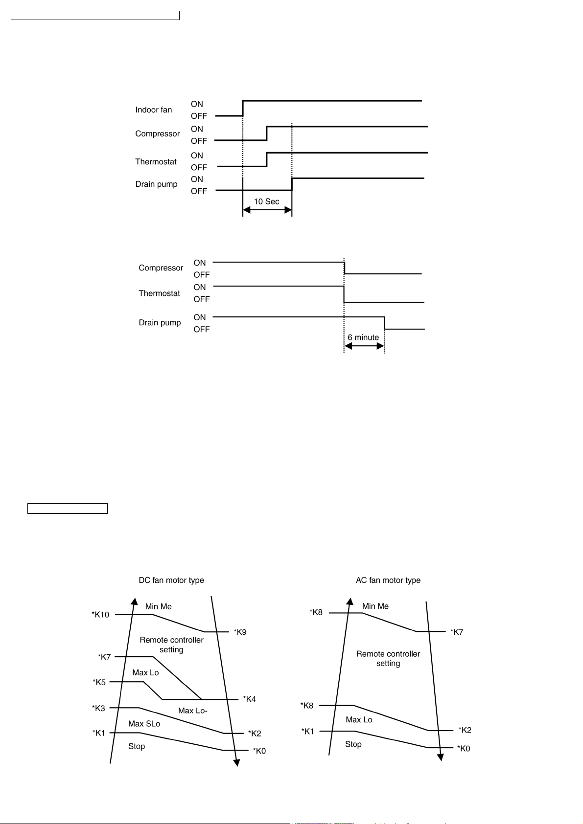
9.3.6. Drain pump control
•
•
During cooling, dry, or defrost operation, drain pump operate by following the below table.
• •
•
•
When compressor start, drain pump operation start after 10 second of indoor fan starting.
• •
•
•
When operation stop or thermostat is off, drain pump continue operating for 6 minute to prevent the drain water from coming
• •
back.
9.3.7. Cooling low temperature protection control
•
•
During cooling, or dry operation, if outdoor temperature is less than -15°C.
• •
−
−
And thermostat on conditio n continue for 15 min, compressor stop.
− −
−
−
After 3 min waiting (restart delay), if thermostat is on, compressor restart.
− −
9.4. Heating Mode Operation
9.4.1. Heating indoor fan control
Fan speed manual
•
•
Fan speed [Hi] [Me] [Lo] set by remote controller.
• •
•
•
However, when operation start, or during operation, fan speed control is limited to due to prevent a cold draft, for example, when
• •
heating operation start.
•
•
(K10 = Indoor heat exchan ger temperature, depend on indoor type)
• •
28
CS-F24DD2E5 CU-L24DBE5 / CS-F28DD2E 5 CU-L28DBE 5 /
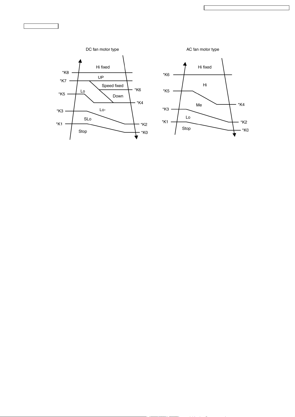
Fan speed auto
•
•
When operation start, or during operation, fan speed control by detecting indoor heat exchanger as follows:
• •
•
•
(K10 = Indoor heat exchan ger temperature, depend on indoor type)
• •
9.4.2. Hot start control
•
•
When heating operation start, hot start control carry out.
• •
•
•
During hot start operation, [PREHEAT] displayed at the wired remote controller.
• •
•
•
For wireless remote controller, [POWER LED] is blinking at the receiver of indoor unit. Indoor fan stop and louver angle fixed
• •
to upper side in spite of any setting of remote controller. When indoor heat exchanger temperature increase, or 4 minute past
after operation start, hot start control finish and shift to normal fan control.
9.4.3. Heating indoor fan control at thermostat off heating mode operation
•
•
During heating operation, if thermostat is off, indoor fan fixed low speed, Louver angle fixed upper side, even if remote control
• •
display shows any angle.
(cassette and ceiling model only)
9.4.4. Heating powerful operation
•
•
When heating mode operation start, temperature differen ces between setting temperature and room temperature is more than
• •
5 K, setting temperature increase 2 K and operation start.
(however, setting temperature after shifting is more than 31°C, setting temperature fixed 31°C.)
•
•
Due to this control, micro computer judge indoor heat loss is big and increase compressor frequency compare to normal
• •
condition, then heat up indoor room quickly.
•
•
This control will be finished after 60 min or thermostat is off.
• •
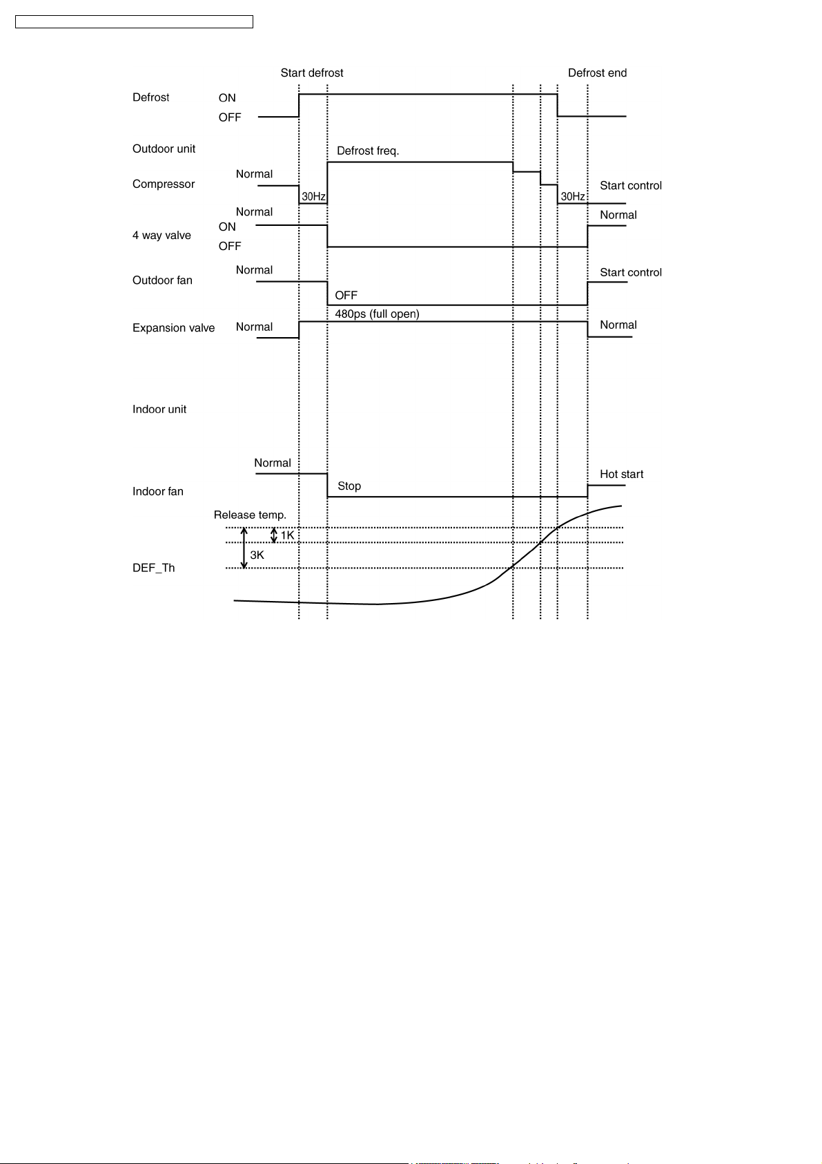
9.4.5. Defrost control
•
•
During heating operation at outdoor low temperature condition, defrost operation start timely to melt the ice formed on outdoor
• •
heat exchanger.
•
•
When heating operation accumulated time is time up, and both outdoor temperature and outdoor unit heat exchanger
• •
temperature is less than setting temperature for 5 minute. When defrost temperature is more than setting temperature, defrost
operation finish.
•
•
During defrost operation, in spite of any change of remote controller, indoor fan stop and louver angle fixed at upper side.
• •
(for louver control : cassette and ceiling model only)
•
•
During defrost operation, [DEFROST] is displayed at wired remote controller (when using wireless controller, POWER LED is
• •
blinking in receiver of indoor unit), hot start operate after defrost operation finish.
29
CS-F24DD2E5 CU-L24DBE5 / CS-F28DD2E 5 CU-L28DBE 5 /
9.4.6. Heating high temperature protection
•
•
During heating operation, when outdoor temperature is more than 35°C for 15 minute, compressor stop to protect compressor.
• •
•
•
After 3 minute (re-start delat control) waiting, if thermostat on conditio n, outdoor unit re-start.
• •
30
 Loading...