

Page 1
Order No: PAPAMY1604052CE
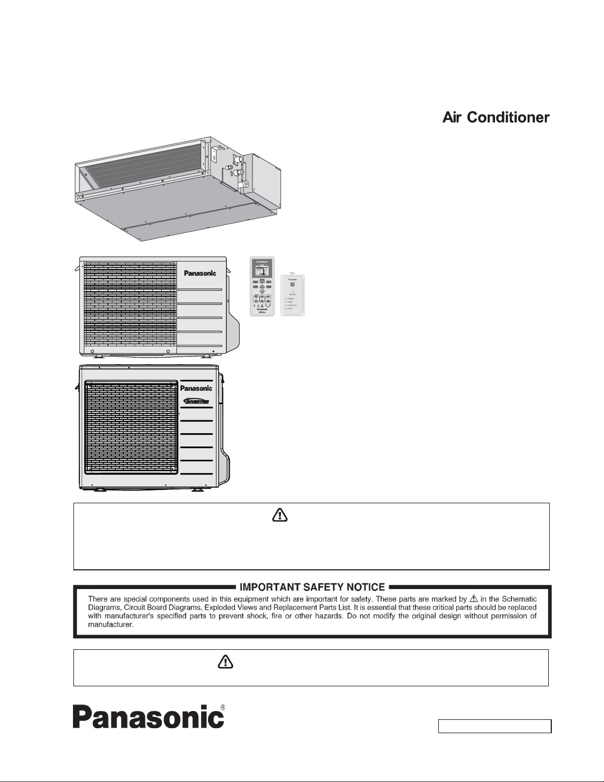
Installation Manual
Indoor Unit Outdoor Unit
CS-E9SD3UAW
CS-E12SD3UAW
CS-E18SD3UAW
CU-E9SD3UA
CU-E12SD3UA
CU-E18SD3UA
Destination
USA
WARNING
This service information is designed for experienced repair technicians only and is not designed for use by the general public.
It does not contain warnings or cautions to advise non-technical individuals of potential dangers in attempting to service a product.
Products powered by electricity should be serviced or repaired only by experienced professional technicians. Any attempt to service
or repair the product or products dealt with in this service information by anyone else could result in serious injury or death.
PRECAUTION OF LOW TEMPERATURE
In order to avoid frostbite, be assured of no refrigerant leakage during the installation or repairing of refrigerant circuit.
© Panasonic Corporation 2016
Page 2
11. Installation Instruction
x IMPORTANT (ONLY FOR E9SD3UAW AND E12SD3UAW)
This product has been designed and manufactured to meet ENERGY STAR
matche
achive rated
cha
efficiency and shorten equipment life.
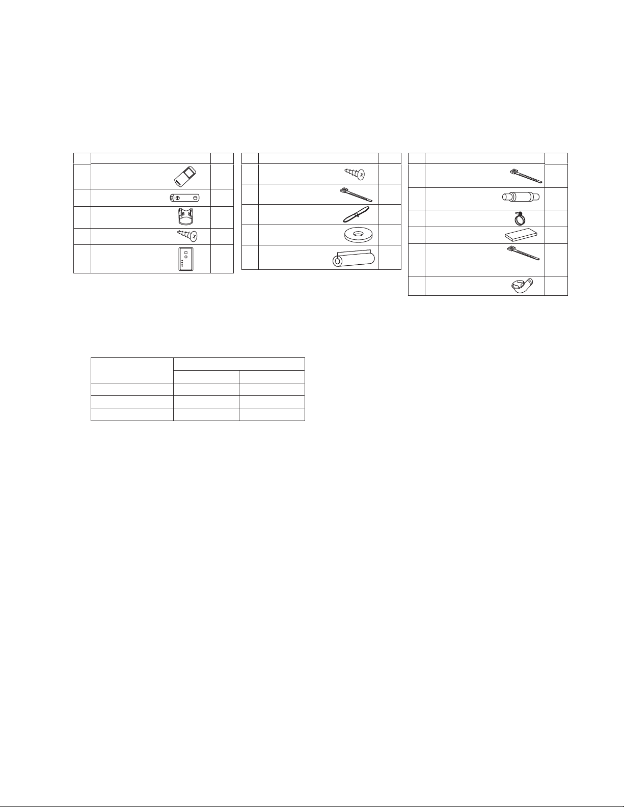
Attached Accessories
d with appropriate coil components. However, proper refrigerant charge and proper air flow are critic
capacity and efficiency. Installation of this product should follow the manufacturer’s refri
rging and air flow instructions. Failure to confirm proper charge and airflow may reduce energy
®
criteria for energy efficiency when
al to
gerant
No. Accessory part Qty.
Remote control
1
Battery
2
Remote control holder
3
Remote control holder
4
fi xing screw
Remote control receiver
5
Ŷ
Requir
ed Materials
No. Accessory part Qty.
Receiver fi xing screw
(M4 x 39/64" (15.5 mm))
6
1
Clamper (band)
(for receiver cable fi xing)
7
2
1
2
1
Receiver cable
(6.56 ft (2 m))
8
Washer
(for suspension fi tting)
9
Flare insulator
(for gas pipe / liquid pipe
0
connection)
No. Accessory part Qty.
Clamper (band)
2
1
1
8
2
(for fl are & drain insulating
!
connection)
Drain hose
(for unit & PVC pipe
@
connection)
Hose band
#
(for drain hose connection)
Drain hose insulation
$
(for drain pipe connection)
Clamper (band)
(for power supply cord)
%
* Be sure to fi x the power supply cord
with clamper (band).
Drain elbow
¥
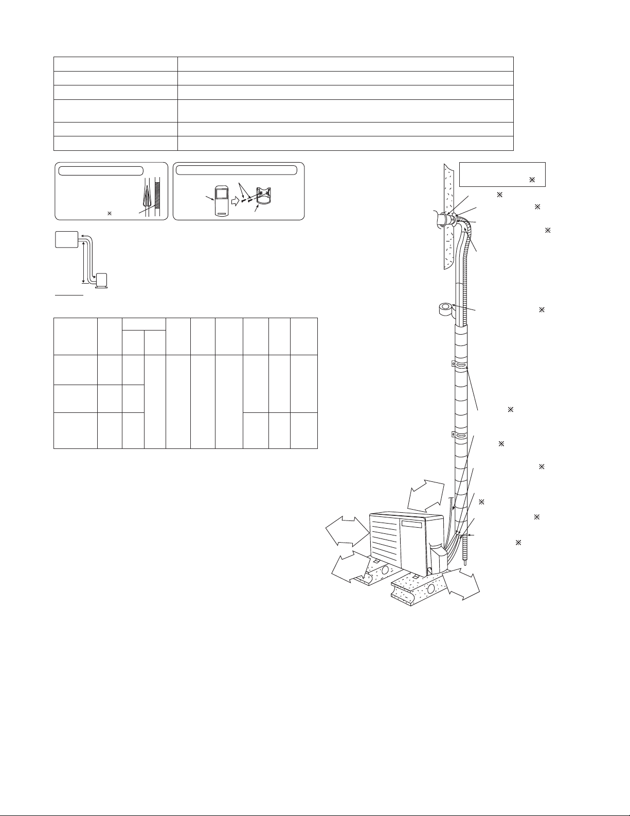
x Read the catalog and other technical materials and prepare the required materials.
x Applicable piping kit
Applicable piping kit
CZ-3F5, 7BP 3/8" (9.52 mm) 1/4" (6.35 mm)
CZ-4F5, 7, 10BP 1/2" (12.7 mm) 1/4" (6.35 mm)
CZ-52F5, 7, 10BP 5/8" (15.88 mm) 1/4" (6.35 mm)
x
Pipe size reducer (CZ-MA1P) for outdoor Multi connection CS-E12SD3UAW, CS-E18SD3UA
Piping size
Gas Liquid
W
L=131
4
1
1
2
1
1
33
Page 3
Ŷ
Other Items to be Prepared (Locally Purchased)
Product name Remarks
Rigid PVC pipe VP20 (outer diameter ø1 1/32" (ø26); also sockets, elbows and other parts as necessary
Adhesive PVC adhesive
Insulation
For refrigerant piping insulation: foamed polyethylene with a thickness of 5/16" (8 mm) or more.
For drain piping insulation: foamed polyethylene with a thickness of 13/32" (10 mm) or more.
Indoor/outdoor connecting cable UL listed or CSA approved 4 conductor wires minimum AWG16
Hanging bolt related parts Hanging bolts (M10) (4) and nuts (12), (when hanging the indoor unit)
Insulation of piping connections
• Carry out insulation after
checking for gas leaks and
secure with vinyl tape.
Vinyl tape
Indoor unit
A
B
Outdoor
unit
IMPORTANT
Begin the installation job from
the “Indoor Unit” installation.
Piping size
Model
E9SD3UAW 9000
E12SD3UAW 11500
E18SD3UAW 17200
Capa-
city
(Btu/h)
Gas Liquid
3/8"
(9.52
mm)
1/2"
1/4"
(12.7
(6.35
mm)
mm)
1/2"
(12.7
mm)
Example: For E9SD3UA
Attaching the remote control holder to the wall
Remote control holder fi xing screws
Remote
control
1
Remote control holder
Min.
Max
Std.
Length
24.6 ft
(7.5 m)
Eleva-
tion
49.2 ft
(15 m)
Piping
Length
9.8 ft
(3 m)
W
Max.
Piping
Length
65.6 ft
(20 m)
100.0 ft
(30.5 m)
If the unit is installed at 32.8 ft (10 m) distance, the
quantity of additional refrigerant should be 1.64 oz
(50 g) …. (32.8 - 24.6) ft x 0.2 oz/ft = 1.64 oz.
((10 - 7.5) m x 20 g/m = 50 g).
4
Additional
Refri-
gerant
0.2
oz/ft
(20
g/m)
0.3
oz/ft
(25
g/m)
3
Piping
Length
for add.
gas
24.6 ft
(7.5 m)
32.8 ft
(10 m)
15
3
/16"
(100 mm)
or more
/16"
15
3
(100 mm)
or more
Installation parts you
should purchase (
Sleeve (
)
Bushing-Sleeve (
Putty
(Gum Type Sealer) (
Bend the pipe as
closely on the wall
as possible, but
be careful that it
doesn’t break.
Vinyl tape (Wide) (
• Apply after carrying
ainage test.
out a dr
To carr
•
y out the
drainage test,
remove the air
fi lters and pour
water into the heat
exchanger.
Saddle (
)
Power supply
cable (
)
Connection cable (
1/4" (6.35 mm)
Liquid side piping
)
(
Gas side piping (
Additional
drain hose (
)
)
)
)
)
)
)
3
/8"
39
(1000 mm)
or more
It is advisable
to avoid more than 2 blockage
11
13
(300 mm)
/16"
or more
directions. For better ventilation & multiple-outdoor
installation, please consult authorized dealer/specialist.
Or
x This illustration is for explanation purposes only.
The indoor unit will actually face a different way.
34
Page 4
11.1 Indoor Unit
11.1.1 Selecting the Installation Location
Take into consideration the following contents when creating the blueprint.
Ŷ
Indoor unit installation location
x Do not install the unit in excessive oil fume area such as kitchen, workshop an
x
The location should be strong enough to support the main unit without vibration.
x There should not be any heat or steam source ne
x
Drainage should be easy. Avoid locating the drain port close to ditches (domestic wastew
Avoid locations above entrances and ex
x
its.
arby.
x Do not block the air intake and discharge passages.
x
Select the location that enables the cool and warm air to spread out
Locate the indoor unit at least 3.28 ft (1 m) or more away from a TV, radio, wireless appliance, antenna cabl
x
fluore
scent light, and 6.56 ft (2 m) or more away from a telephone.
to the entire room.
x Recommended installation height for indoor unit shall be at least 8.27 ft (2.5 m) from floor.
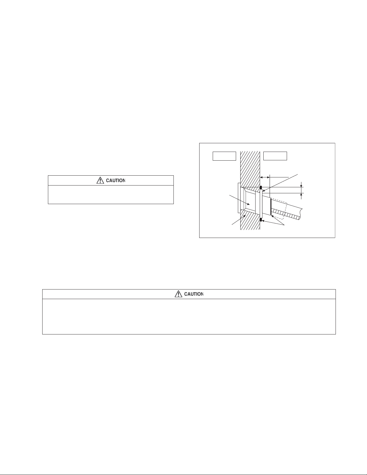
11.1.2 To Drill a Hole in the Wall and Install a Sleeve of Piping
1 Insert the piping sleeve to the hole.
2 Fix the bushing to the sleeve.
3 Cut the sleeve until it extrudes about 19/32"
(15 mm) from the wall.
When the wall is hollow, be sure to use the sleeve for tube
assembly to prevent pests from damaging the cables, e.g.
mice biting the connection cable.
4
Finish by sealing the sleeve with putty or
caulking compound at the final stage.
Indoor
Sleeve
for tube
assembly
3
ø
/4
2
"
(ø70 mm)
through hole
d etc.
Wall
ater).
Outdoor
Bushing for
19
/32"
(15 mm)
Putty or caulking compound
tube assembly
e and
Approx.
7
/32
" -
9/32
(5 - 7 mm)
"
11.1.3 Installing the Indoor Unit (Installation Embedded in the Ceiling)
11.1.3.1 Preparation Before Installation
x Always provide sufficient entry and exit space to allow installation work, inspection and unit replacement.
x Waterproof the rear surface of the ceiling below the unit in consideration of water droplets forming and dropping.
When cooling operation is performed for an extended period under the following conditions, water droplets may form and drop. Attach locally
purchased insulation (foamed polyethylene with a thickness of 7/32" (5 mm) or more) to the outside of the indoor unit before installing into the
ceiling to improve heat insulation.
x Locations with a dew point inside the ceiling of 73.4°F (23°C) or more
x Kitchens and other locations that produce large amounts of heat a
x
Locations where the inside of the ceiling serves as
x When ins
air to spre
talling into a ceiling, select the unit position and airflow direction that enable the cool and wa
ad out to the w
hole room.
an outside air intake passage
x Do not place objects that might obstruct the airflow
nd steam
rm
within 3.28 ft (1 m) below the intake grill.
35
Page 5
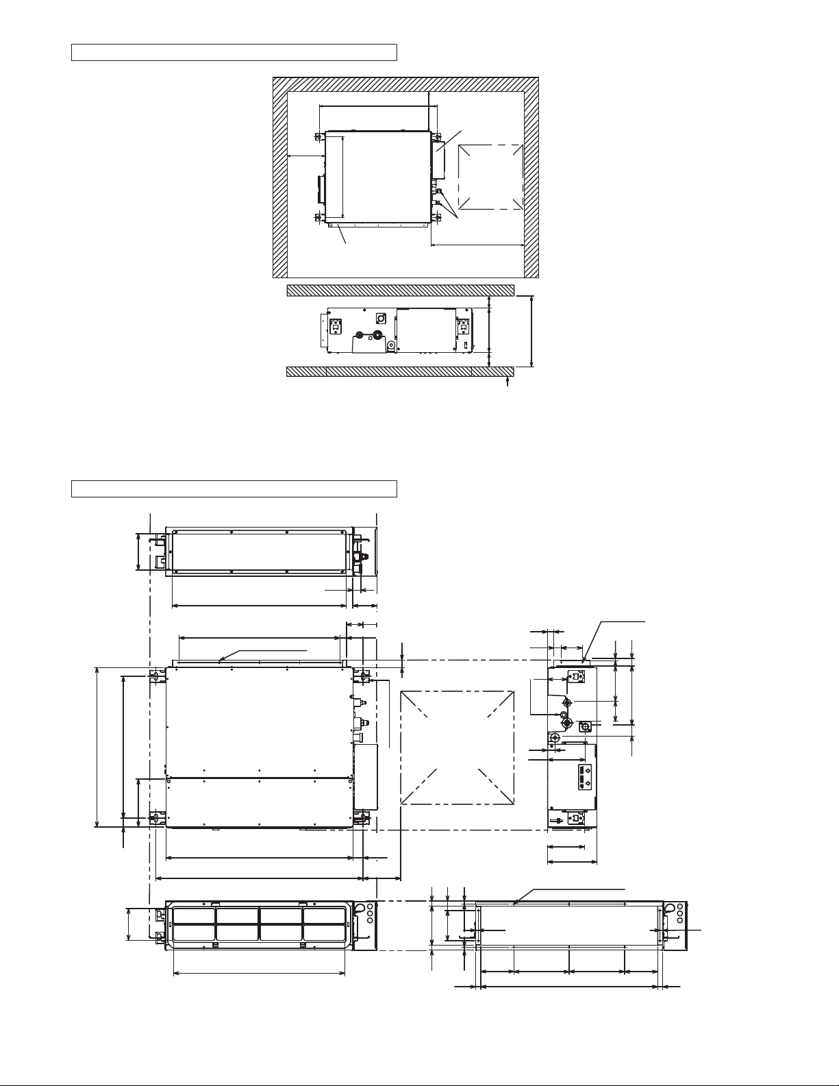
Required Minimum Space for Installation and Service
7
/16" (
824) (Suspension bolt pitch)
32
7
/8"
Min. 7
(
200) or
more
Min 3 15/
564)
(
"
/32
7
22
Flange for air outlet duct
" (100 mm) or more for bottom
16
air intake
x
H dimension means the minimum height of the unit installation space.
"
/8
7
or
200)
Min.
more
(
7
Min. 25/32" (20) or more
Min. 25/32" (20) or more
Electrical
component box
Inspection
access
23
/32
17
23
/32
17
(
450 x 450)
Refrigerant tubing
19
/32
Min. 25
(
650) or more
" (200)
/8
7
7
Ceiling
x
"
"
"
" (240)
/16
*H=Min.
7
9
x Select H dimension such that a downward slope of at least 1/100 is ensured. Refer to 11.1.4 “Connecting
drain pi
ping
”
Dimension of the Indoor Unit
the
" (145)
/32
23
5
27
(640)
"
/16
3
25
194)
" (564) (Suspension bolt pitch)
" (
/32
/8
7
5
7
22
(38)
"
/2
1
1
(126)
"
/32
31
4
1
/4
"
(692) (Flange for air outlet duct)
3
/16
" (640) (6
25
7
/16
32
" (824) (Suspension bolt pitch)
5-ø
29
26
1
"
/8
17
/32
25
/32
"
5
/16
" (160) x 4)
(ø3.1)(Hole)
" (750)
(680)
5
/32
" (29)
1
25
/32
" (96)
3
5
/8
2
" (66)
1
/32
1
1 15/32
5 29/32"
"
(37)
(150)
(26)
1
(27)
1
/16"
Inspection access
23
17
Suspension lug
/32" X
(450x450)
(Field supply)
"
(22)
"
/8
7
"
/32
3
(155)
6
(23)
"
/32
29
(40)
"
/16
9
1
"
/32
23
4
29
19
"
/32
/32
9
(120)
(15)
17
(14)
"
/16
(23)
"
23/32"
9
/16
5
(132)
3
" (28)
/32
1
3
1
/16
" (30)
3
/16
3
1
(33)
6
(153)
"
(14)
3
/16
"
3
(84)
" (81)
Water inlet
5
"
/16
1
"
/32
29
5
" (150)
/32
7
/8
7
1
10-ø
"
/8
21
/32
8
"
(220)
23
/32
27
* Filter Uninstalled
1
2-ø
(Hole)
5
"
/16
"
/32
13
"
/8
5
5
"
/32
5
3
" (200)
(ø3.1)(Hole)
21
8
"
/32
(220)
" (704)
"
/8
(10)
(ø3.1)
"
/16
3
1
(143)
(80)
" (44)
/32
23
1
3
/16
5
(132)
(30)
" (238)
/8
3
9
"
29
/32
"
(23)
9
/16
" (14)
36
Page 6

In Case of Bottom Intake
1
Remove the frame filter assy as shown in
diagram 1
2 Remove cover plate as shown in diagram 1
3 Fix frame filter assy as shown in diagram 2
4 Fix cover plate as shown in diagram 2 with
the dummy hole downward.
Fixing Frame Filter Assy
Filter Assy
In case of bottom side
Ceiling Opening
* Attach the frame fi lter assy to
the main unit while pushing the
tip of the latches in the direction
of the arrow.
Main unit
1
Air
discharge
Air intake
Cover plate
Dummy hole
In case of back side
Frame Filter
Assy
Cover plate
2
Air discharge
Air intake
Dummy hole
Frame
Filter
Assy
x
Install inspection opening 17 23/32" x 17 23/32" (450 mm x 450 mm) on the control box side where maintenan
spection of the control box and drain pump are easy. Install another inspection opening
and in
31 1/2" x 27 9/16"
(800 mm x 700 mm) also at the lower part of the unit.
9
27
" (700)
/16
700
Hanging
bolt M10
(2
" (800)
800
/2
1
31
Reinforcing materials
3
17
3
/8
/32
" to
" (144)
/2
1
Approx.
4
") (60 to 90 mm)
Roof beam
Ceiling surface
Securing the Hanging Bolts
Reinforced concrete
Hanging
bolt M10
/2" (114)
1
Approx.
4
discharge
Insert hole-in
anchor, etc.
”
Ceiling surface
Air intakeAir
A
Ceiling
Wooden of other structure
9
/16
" (40)
1
3
/32
t =
3
" (30)
/16
1
(Hanging bolt pitch)
Hanging bolt
C channel
Hanging fi xture
" (2)
Allow view A
Inspection access
(Field supply)
ce
x
Secure the hanging bolts (M10, locally purchased) firmly in a manner capable of supporting the unit weight
Consult your construction or interior contractor for details on finishing the ceiling opening
x
.
37
.
Page 7

Installing an Intake and Discharge Duct Type
Ensure the range of unit external static pressure is not exceeded. Refer technical manual for the rang
x
external stati
x
Connect the duct as sh
When attaching duct to the intake side, remove the product filter frame assy and replace with locally purcha
x
c pressure se
own.
tting.
intake-side flange by using flange by using 10 - Ø 1/8" (Ø 3.1)(hole) screws.
x Wrap the flange and duct connection area with aluminium tape or similar to prevent air leak.
e of
se
Flange
(locally purchase)
Connection screw (x10)
Rectangular solic duct
When attaching a duct to the intake-side, be sure to attach
an air filter inside the air passage on the intake-side.
(Use an air filter with dust collecting efficiency at least 50%
in a gravimetric technique.)
Installation into the Ceiling
Attach the nuts and washers to the hanging bolts, then lift up and hook the main unit onto the hanging fixtures.
x
Main unit
Flange
Insulation material
(locally purchased)
Air outlet sideAir inlet side
x Check if the unit is leveled using a level or a vinyl hose filled partially with water.
Hanging bolt (M10)
(locally purchased)
Washer
9
Hexagonal nut (M10)
(locally purchased)
Level
38
Page 8

Mounting Remote Controller Receiver
Install the remote controller receiver cable at least 1 31/32" (50 mm) away from electric wires of other appliances to avoid miss-operation
(electromagnetic noise).
1
Remove the bottom case.
Insert the driver
and slightly turn.
tention
At
Mounting the bottom case
x Tighten the screws securely until the screw head
touch the b
head
when mounting the top ca
Do not over-tighten the screws. (The bottom ca
x
may be deformed, re
ottom case. (Otherwise, loose scre
s may hit the PCB and cause malfunction
se.)
g in fall of the unit.)
sultin
w
se
Bottom
case
s
Flat-blade
screwdriver
Screws
6
necting the remote control wiring
Con
x Arrange the wires as shown in the illustration for 2 as in diagram below, avoiding unnecessary wires bei
store
d in the case. (Caught wires ma
Avoid wires touching parts on the PCB. (Caught wires may destro
x
Mount to the wall.
2
EXPOSED TYPE
Prepara
tion: Make 2 holes for screws using a driver.
Mount the top case.
• Align the claws of the
top case and then align
the claws of the bottom
case.
Cut here with
a nipper and
remove the burr
le.
with a fi
Claw (2 places)
Claw
Wood screw (supplied)
Connect the remote control wiring.
• Arrange the wires along the groove of the case.
Mount the bottom case
to the wall.
Hole for screw
Wall to fi x the
receiver
y destroy the PCB.)
Prepara
y the PCB.)
EMBEDDED TYPE
tion: Make 2 holes for screws using a driver.
Mount the top case.
• Align the claws of the
top case and then
align the claws of the
bottom case.
Avoid the wire
being caught.
Claw (2 places)
Wood screw (supplied)
Connect the remote control wiring.
Mount the bottom case to the wall.
• Pass the wire through the hole in
the centre of the bottom case.
Claw
Hole for screw
ng
Top case
(Back side)
Bottom case (Back side)
Clamper 7
(supplied)
Pass
through
the hole
39
Top case
(Back side)
Bottom case (Back side)
Terminal board
Page 9

x Connect the indoor unit and the remote control receiver 5. (Refer to the illustrati
Fix the green wire from receiver cable 8 to the grounding location provided inside control
x
Receiver cable 8
Control box
Remote control
receiver
on.)
board.
5
11.1.4 Connecting the Drain Piping
x Lay the drain piping so as to ensure drainage.
x Use a locally purchased VP20 general rigid PVC pipe (outer diameter ø1 1/32" (ø26)) for the drain piping a
connect the indoor unit and the drain piping using supplied hose band to ensure that no leakag
firmly
occurs.
x Drain piping located indoor should always be insulated by wrapping with locally purchased insulation (foa
polyethylene
x
The drain piping should have a downward gradient (1/100 or more) and should be secured by using pipe ha
equipm
with a thickness of 13/32" (10 mm) or more
ent to avoid creating hills or traps partway.
).
x Should there be any obstacle preventing the drain piping from being extended smoothly, the drain piping can be
raised out
side of the main unit as shown in the illustration below.
nd
e
med
nging
Drain hose
1
/32
1
1
"
/8
(130)
#
Hard PVC pipe (VP20)
@
Adhere with
PVC adhesive.
$
"
(26)
Rise
At least 1/100
Good
Hill
13
" (300 mm) or less
11
/16
(not a downward gradient)
11
/16
" (500 mm) or less
19
Tr ap
Unit drain port
Do not use adhesive.
x Strictly do not install and extend the drain piping from the main unit drain water outlet horizontally or upward or raised it 19 11/16" (500 mm)
or more.
Doing so ma
x Do not use drain hose bent at 90° angle. (The maximum permissible bend is 45°.)
Hose band
Drain hose insulation
1
/32" (26)
1
5
y result in poor drainage or drain motor failure.
11.1.5 Insulating the Refrigerant Piping
x After the piping is connected, insulate. (Refer to the illustration)
Clamper
!
Wrap fi rmly
with vinyl tape,
leaving no gaps.
Unit side
40
Wrap fi rmly
with vinyl tape,
leaving no gaps.
Flare insulator
0
Page 10

11.1.6 Connect the Cable to the Indoor Unit
x Remove control box cover.
Remove
x
Fix the conduit connections to the knockout holes
x
the plug
together with lock nuts, then secure them against
the cont
rol box side pan
x Receiver cable wires 8 must pass through the
uppe
r conduit
Make
sure the receiver cable is inserted
inside of the control box.
Connect receiver cable connector to control box
wire
connector and fix it to the power su
r as shown in the diagram.
holde
Insert firmly the connector of receiver cable 8
con
nector at control box of indoor un
Connection cable between indoor un
x
outdoo
r unit should be UL listed or
ductor wires minimu
4 con
accordan
ce with local electric codes.
o Ensure that the terminal numbers on
indoo
r unit are connec
terminal n
right coloured wires as shown in the diagram.
o Earth lead wire should be longer than th
other lea
electri
out from the anchorage.
Secure the cable onto the control board
o
the holde
s.
el.
hole.
from
pply cord
it.
it and
CSA approved
m AWG16 in
the
ted to the same
umbers on the outdoor un
it by the
d wires as shown in the diagram
cal safety purpose in case the cord
r (clamper).
to
e
for
slips
with
Control Box
Control Box cover
Lock Nuts
Plugs
Connectors
Knockout holes
Screws
Fix the receiver cable to the holderFix receiver cable connector
Terminals on the indoor unit 1 2 3
Colour of wires
Terminals on the outdoor unit 1 2 3
When the wall is hollow, please be sure to use the sleeve
for tube ass’y to prevent dangers caused by mice biting the
connection cable.
Earth wire
(connection cable)
Indoor/outdoor connection terminal
This equipment must be properly earthed.
x
Ensure the colour of wires of outdoor un
terminal
Holder for
connection cable
WARNING
Earth wire
(receiver cable)
Indoor/outdoor
connection cable
Nos. are the same to the indoor’s
respectively.
x
Earth wire shall be Yellow/Green (Y/G) in colo
and lon
ger than other AC wires for safety reason.
it and the
ur
41
Page 11

11.1.6.1 Wire Stripping and Connecting Requirement
Wire stripping
Indoor/outdoor
connection
terminal board
7
10 ± 1 mm
13/32" ± 1/32"
No loose strand when inserted
/32" (5 mm)
or more
(gap between wires)
Do not joint wires
WARNING
RISK OF FIRE
JOINING OF WIRES MAY CAUSE
OVERHEATING AND FIRE.
Use complete wire without joining.
Use approved socket and plug with earth pin.
Wire connection in this area must follow to national wiring rules.
OR
Conductor
fully inserted
ACCEPT
Conductor
over inserted
PROHIBITED
OR
Conductor not
fully inserted
PROHIBITED
OR
42
Page 12

11.2 Outdoor Unit
11.2.1 Select the Best Location
11.2.2 Install the Outdoor Unit
x After selecting the best location, start installation to Indoor/Outdoor Unit Installation Diagram.
1
Fix the unit on concrete or rigid frame firmly and horizontally with a bolt nut (ø 13/32" (ø10 mm)).
2 When installing at roof, please consider strong wind and earthqua
Please fa
sten the installation stand firmly with bolt or nails.
ke.
AB
C
D
11.2.3 Connect the Piping
11.2.3.1 Connecting the Piping to
Indoor
Please make flare after inserting flare nut (locate at
joint portion of tube assembly) onto the copper pipe.
(In case of using long piping)
Connect the piping
x Align the center of piping and suffici
the flare nut
with fingers.
x Further tighten the flare nut with torque wren
cified torque as stated in
spe
the table.
ently tighten
ch in
11.2.3.2 Connecting the Piping to
Outdoor
Decide piping length and then cut by using pipe cutter.
Remove burrs from cut edge.
Make flare after inserting the flare nut (locate at valve)
onto the copper pipe.
Align center of piping to valve and then tighten with
torque wrench to the specified torque as stated in the
table.
Model A B C D
E9SD3UAW,
E12SD3UAW
E18SD3UAW
Do not over tighten, overtightening may cause gas leakage.
Piping size Torque
1/4" (6.35 mm) 13.3 Ibf•ft [18 N•m (1.8 kgf•m)]
3/8" (9.52 mm) 31.0 Ibf•ft [42 N•m (4.3 kgf•m)]
1/2" (12.7 mm) 40.6 Ibf•ft [55 N•m (5.6 kgf•m)]
5/8" (15.88 mm) 47.9 Ibf•ft [65 N•m (6.6 kgf•m)]
3/4" (19.05 mm) 73.8 Ibf•ft [100 N•m (10.2 kgf•m)]
22 7/16"
(570 mm)
24 1/8"
(613 mm)
4 1/8"
(105 mm)
5 5/32"
(131 mm)
23/32"
(18.5 mm)
5/8"
(16 mm)
Spanner
or Wrench
To r qu e
wrench
12 19/32"
(320 mm)
14 3/16"
(360.5 mm)
11.2.3.3 Connecting the Piping to
Outdoor Multi
Decide piping length and then cut by using pipe cutter.
Remove burrs from cut edge.
Make flare after inserting the flare nut (locate at valve)
onto the copper pipe.
Align center of piping to valve and then tighten with
torque wrench to the specified torque as stated in the
table.
Male side
(Auxiliary pipe)
Wrench
(Adjustable Wrench)
Male side
(Auxiliary pipe)
Wrench
(Adjustable Wrench)
Torque Wrench for Flare
Nut and Pipe Size Reducer
Hall Union
Hall Union
Flare Nut
Packing
(Connection pipe)
Torque Wrench
for Flare Nut
Pipe Size
Reducer
Female side
Applicable to
Liquid and Gas side of
CS-E9SD3UAW
Liquid side of
CS-E12SD3UAW
CS-E18SD3UAW
Flare Nut
(Connection pipe)
Applicable to
Gas side of
CS-E12SD3UAW
CS-E18SD3UAW
Female side
11.2.3.4 Gas Leak Checking
Pressure test to system to 400 PSIG with dry nitrogen, in stages. Thoroughly leak check the system. If the pressure
holds, release the nitrogen and proceed to section 4.
43
Page 13

11.2.4 Evacuation of the Equipment
WHEN INSTALLING AN AIR CONDITIONER, BE SURE TO EVACUATE THE AIR INSIDE THE INDOOR UNIT AND
PIPES in the following procedure.
Indoor unit
Vacuum
pump
1
Connect a charging hose with a push pin to the Low side of a charging set and the service port of the 3-way
Liquid side
Gas side
Two-way valve
Close
Three-way valve
Close
Outdoor unit
valve.
2 Connect the micron gauge between vacuum pump and service port of outdoor units.
3 Turn on the power switch of the vacuum pump and make sure that connect digital micron gauge and to pull
down to a value of 500 microns.
4 To make sure micron gauge a value 500 microns and close the low side valve of the charging set and turn off
the vacuum pump.
5 Disconnect the vacuum pump house from the service port of the 3-way valve.
6 Tighten the service port caps of the 3-way valve at a torque of 13.3 Ibf•ft (18 N•m) with a torque wrench.
7 Remove the valve caps of both of the 2-way valve and 3-way valve. Position both of the valves to “Open”
using a hexagonal wrench (5/32" (4 mm)).
8 Mount valve caps onto the 2-way valve and the 3-way valve.
o Be sure to check for gas leakage.
x If micron gauge value does not descend 500 microns, take the following measures:
If the leak stops when the piping connections are tightened further, continue working from step 3
-
-
If the leak does not stop when the connections are retightened, re
-
Do not release refrigerant during piping work for installation and reinstallation.
Be careful with the liquid refrigerant, it may cause fr
-
ostbite.
pair location of leak.
.
44
Page 14

11.2.5 Connect the cable to the Outdoor Unit
x For model E9SD3UAW, E12SD3UAW
1 Remove
2 Remove Control Board Cover (Resin and
Metal).
3 Remove Plugs.
4 Fix the conduit connectors to the knockout
holes with lock-nuts, then secure them against
the side panel.
5 All wires pass through conduits.
6 Connection cable between indoor unit and
outdoor unit should be UL listed or CSA
approved 4 conductor wires minimum AWG16
in accordance with local electric codes.
7 Wire connection to the power supply
(208/230V 60Hz) through circuit breaker.
o Connect the UL liste
Connect the power supply cord and connection cable between indoor unit and outdoor unit according to the
8
diagram below.
Top panel.
s minimum AWG14 to
wire
board, and co
ct the other end of the
nne
wires to ELCB / GFCI.
d or CSA approved
the terminal
Control Board
Metal Cover
Control Board
Cover (Resin)
To p Pa n e l
Powe r
Supply
Wires
Lock Nuts
Knockout
Holes
Plugs
Side Panel
Connectors
Indoor Unit
Outdoor Unit
lanimreTlanimreT
1
2
3
9
Secure the wire onto the control board with the holder (clamper).
208/230V min AWG16
208/230V min AWG16
208/230V min AWG16
Grounding wire min AWG16
* Ensure all connecting wire
between indoor unit and
outdoor unit and power supply
cord are installed in individual
conduit.
1
2
3
L1
L2
Disconnect
Switch
Field supply
Grounding wire
ower Supply
P
Single Phase
208/230V 60Hz
min AWG14
10 After completing wiring connections, reattach the control board cover (Metal and Resin) and the top panel to
the original position with the screws.
11 For wire stripping and connection requirement, refer to instruction 11.1.6 of indoor unit.
Terminal
Board
Earth
wire
longer
than
other AC
wires for
safety
reasons
Earth
wire
longer
than
other AC
wires for
safety
reasons
Holder
Powe r
supply cord
This equipment must be properly earthed.
x
Earth lead wire shall be Yellow/Green (Y/G) in colour and should be longer than other lead wires as shown in
figure for el
ectrical safety in case of slippi
ng.
Indoor & outdoor
connection cable
WARNING
45
the
Page 15

x For model E18SD3
Remove control board cover (Resin and
1
UAW
Metal).
2 Remove particular plate.
3 Remove plugs.
4 Fix the conduit connectors to the knockout
holes with lock-nuts, then secure them against
the side panel.
5 All wires pass through conduits & particular
plate’s opening hole.
6 Connecting wire between indoor unit and
outdoor unit should be UL listed or CSA
approved 4 conductor wires minimum AWG16
in accordance with local electric codes.
7 Wire connection to the power supply
(208/230V 60Hz) through circuit breaker.
o Connect the UL liste
s minimum AWG12 to
wire
board, and co
d or CSA approved
the terminal
nne
ct the other end of the
wires to ELCB / GFCI.
Connect the power supply cord and connecting wire between indoor unit and outdoor unit according to the
8
diagram below.
Front Panel
Particular
Plate
Lock Nuts
Knockout
Holes
Connecting Wires
Particular Plate’s
opening holes
Control Board
Cover (Metal)
Plugs
Connectors
Control Board
Cover (Resin)
Indoor Unit
Outdoor Unit
TerminalTerminal
1
2
3
9
Secure the wire onto the control board with the holder (clamper).
208/230V min AWG16
208/230V min AWG16
208/230V min AWG16
Grounding wire min AWG16
* Ensure all connecting wire
between indoor unit and
outdoor unit and power supply
cord are installed in individual
conduit.
1
2
3
L1
L2
Disconnect
Switch
Field supply
Grounding wire
Power Supply
Single Phase
208/230V 60Hz
min AWG12
10 After completing wiring connections, reattach the particular plate and control board cover (metal and resin) to
the original position with the screws.
11 For wire stripping and connection requirement, refer to instruction 11.1.6 of indoor unit.
Terminal
Board
Earth
wire
longer
than
others
AC wires
for safety
reasons
Holder
Terminal
Board
Earth
wire
longer
than
others
AC wires
for safety
reasons
Holder
Power
supply cord
This equipment must be properly earthed.
x
Earth lead wire shall be Yellow/Green (Y/G) in colour and longer than other lead wires for el
Indoor & outdoor
connection cable
WARNING
of the slipping.
46
ectrical safety in case
Page 16

11.2.6 Piping Insulation
1 Please carry out insulation at pipe connection portion as mentioned in Indoor/Outdoor Unit Installation
Diagram. Please wrap the insulated piping end to prevent water from going inside the piping.
2 If drain hose or connecting piping is in the room (where dew may form), please increase the insulation by
using POLY-E FOAM with thickness 1/4" (6 mm) or above.
Switching the High State Switch (SW2)
x To increase the air volume, open the control box and on the control board, switch the FAN switch (SW2) to “HI”.
x See the diagram for “Connecting the Indoor/Outdoor Connection Cable”.
Note: Enabling Long-range Remote Control
x To maintain EMC emission limits, cabling interconnecting the HA terminal and subsequent opto-coupler, must be
no more than 6.2 ft (1.9 m) length.
x Loop four turns of this cable through a suitable small EMC ferrite toroid, and protect with a short length of large
diameter heat-shrink tube.
x There is no similar length limit for cable following on from the opto-coupler isolation.
DISPOSAL OF OUTDOOR UNIT DRAIN WATER
x If a drain elbow is used, the unit should be placed
on a stand which is taller than 1 3/16" (30 mm).
x If the unit is used in an area where temperature
falls below 32°F (0°C) for 2 or 3 days in
succession, it is recommended not to use a drain
elbow, for the drain water freezes and the fan will
not rotate.
CHECK THE DRAINAGE
Check after connecting the power supply.
x Pour approximately 600 cc of water into the drain
pan of the main unit using a squeeze bottle, etc.
x Press the drain test run switch on the control
board in the control box to start the drain motor
and check whether the water drains normally.
(The drain motor operates for approximately
5 minutes and then stops automatically.)
(See the diagram for “Connecting the
Indoor/Outdoor Connection Cable”.)
¥
Install the hose at an angle so that the water smoothly flows out.
Heat
exchanger
Drain pan
HoseDrain elbow
Squeeze bottle
Approximately
600 cc of water
47
 Loading...