

Page 1
Order No: PAPAMY1501049CE
/
MP
O
S
O
123
C
/
TEM P
O
TIMER
S
O
2
3
CHEC
K
Installation Manual
FAN
AUTO
SPEED
HEAT
COOL
DRY
FAN
OFF/ON
FF/ON
ECONAVI
MODE
TEMP
TE
POWERFUL/
FANSPEED
QUIET
TIMER
TIMER
ON
123
FF
SETCHE CKCLOCK RESET
HECK
AIR
SWING
AUTO
COMFORT
AIRSWING
ET
SET
CANCEL
CANCELONOFF
AC RC
CS-E12RKUAW
CS-E18RKUAW
Indoor Unit Outdoor Unit
CS-E9RKUAW
CU-E9RKUA
CU-E12RKUA
CU-E18RKUA
AUTO
HEAT
COOL
DRY
FAN
ECONAVI
MODE
POWERFUL/
QUIET
TIMER
ON
123
1
FF
SETCHE CKCLOCK RESET
CS-E24RKUAW
CU-E24RKUA
Destination
FAN
SPEED
AIR
SWING
AUTO
OFF/ON
FF/ON
COMFORT
TEMP
AIRSWING
FANSPEED
SET
ET
CANCELONOFF
CANCEL
AC RC
USA
Canada
Please file and use this manual together with the service manual for Model No. CU-2E18NBU and CU-5E36QBU, Order No.
PHAAM1111120A1 and PAPAMY1312037CE.
WARNING
This service information is designed for experienced repair technicians only and is not designed for use by the general public.
It does not contain warnings or cautions to advise non-technical individuals of potential dangers in attempting to service a product.
Products powered by electricity should be serviced or repaired only by experienced professional technicians. Any attempt to
service or repair the products dealt with in this service information by anyone else could result in serious injury or death.
PRECAUTION OF LOW TEMPERATURE
In order to avoid frostbite, be assured of no refrigerant leakage during the installation or repairing of refrigerant circuit.
© Panasonic Corporation 2015.
Page 2
11. Installation Instruction (E9RK and E12RK)
11.1 Select the Best Location
11.1.1 Indoor Unit
Do not install the unit in excessive oil fume area
such as kitchen, workshop and etc.
ed.
level.
Max.
Piping
Length
65.6 ft
(20 m)
steam
ng the air
into
oor unit
ion from
wall,
for
ould be
Additional
Refrigerant
0.2 oz/ft
(20 g/m)
Piping
Length
for add.
gas
24.6 ft
(7.5 m)
There should not be any heat source or
near the unit.
There should not be any obstacles blocki
circulation.
A place where air circulation in the room is good.
A place where drainage can be easily done.
A place where noise prevention is taken
c
onsiderat
Do not install the unit near the door way.
ion.
Ensure the spaces indicated by arrows from the
wall, ceili
ng, fence or other obstacles.
Recommended installation height for ind
shall be at least 8 ft (2.4 m).
11.1.2 Outdoor Unit
If an awning is built over the unit to prevent direct
sunli
ght or rain, be careful that heat radiat
the con
There should not be any animal or plant which
coul
Keep the spaces indicated by arrows from
ceiling, fence or other obstacles.
Do not place any obstacles
sho
If piping length is over the [piping length
addition
adde
Recommended installation height for outdoor un
sho
Model
E9RKUAW 9000
E12RKUAW 11500
denser is not obstructed.
d be affected by hot air discharg
which may cause a
rt circuit of the discharged air.
al gas], additional refrigerant sh
d as shown in the tabl
e.
uld be above the seasonal snow
Capacity
(Btu/h)
Piping siz e
Gas
3/8"
(9.52 mm)
1/2"
(12.7 mm)
Liquid
1/4"
(6.35 mm)
Std.
Length
24.6 ft
(7.5 m)
Max.
Elevation
49.2 ft
(15 m)
Min.
Piping
Length
9.8 ft
(3 m)
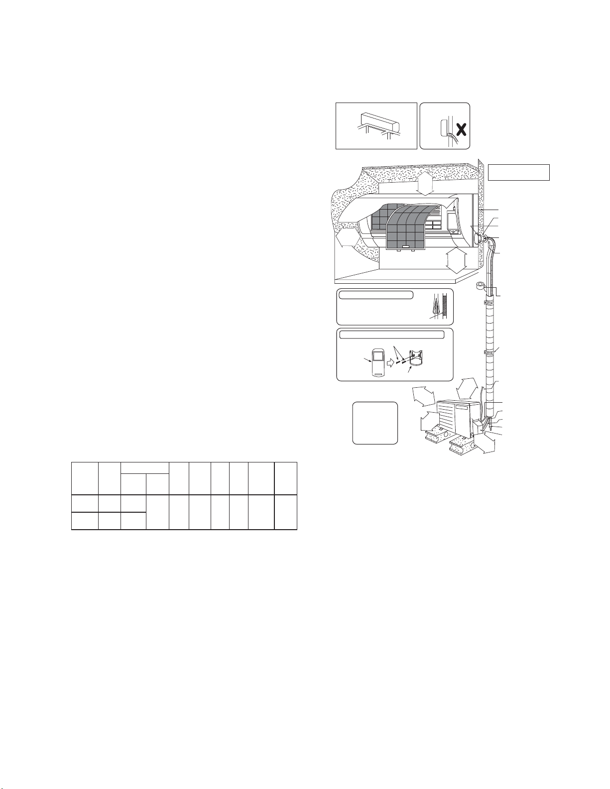
11.1.3 Indoor/Outdoor Unit Installation
Diagram
Piping direction Do not bend up
Right
Rear
Right
bottom
31
1
/
32
"
(50 mm)
or more
Insulation of piping connections
• Carry out insulation after
checking for gas leaks and
secure with vinyl tape.
Attaching the remote control holder to the wall
Remote control holder fixing screws
Remote
3
control
It is advisable to
avoid more than 2
blockage directions.
For better ventilation
& multiple-outdoo r
installation, please
it
consult authorized
dealer/specialist.
•
This illustration is for
explanation pu rposes only.
The indoor unit will actually face
a d ifferent way.
(Front side)
Left
Rear
Left
Left bottom
(Left a nd ri ght are identical)
Floor / Grade level
Ú
Vinyl tape
Remote control holder
drain hos e
9
6
3
1
(
1
0
0
o
m
r
m
o
Installation parts you
"
)
6
1
m
/
e
5
m
r
o
0
0
m
r
(1
o
(
3
o
r
should purchase (Ú)
Installation plate 1
Bushing-Sleeve (
Sleeve (
Putty (
(Gum Type Sealer)
Bendthepipeas
closely on the wall as
possible, but be careful
that it doesn’t break.
Vinyl tap e (wide) (Ú)
• Apply after carrying
out a drainage test.
• To carry out the
drainage test,
remove the air filters
and pour water into
the heat exchanger.
Saddle (
Conduit
(Power supply cord (
Conduit
(Connection cable)
Liquidsidepiping(
Gas side piping (
Additional drain hose (
1
Control Bo ard cover
1
1
3
0
/
0
1
6
m
"
m
m
o
)
r
e
Ú
)
Ú
)
Ú
)
Ú
)
Ú
))
Ú
)
Ú
)
Ú
)
)
"
re
m
16
m
/
65
2
or mo
(
)
m
ore
t(2.4
f
or m
8
5
5
/
1
6
"
m
)
r
e
8
/
3
9
3
0
0
0
1
r
(
o
1
3
"
)
m
m
e
r
o
m
Example: For E9RKUA
W
If the unit is installed at 32.8 ft (10 m) distance, the
quantity of additional refrigerant should be 1.64 oz
(50 g) .... (32.8 - 24.6) ft x 0.2 oz/ft = 1.64 oz.
((10 -7.5) m x 20 g/m = 50 g).
33
Page 3

11.2 Indoor Unit
M
11.2.1 How to Fix Installation Plate
The mounting wall shall be strong and solid enough to prevent it from the vibration.
More than
1
/16" (128 mm)
Installation plate 1
” at 5 position
37/32"
Wall
2
Dimension
179/32"
(439 mm)
More than 1
17"
(432 mm)
easuring
Ta p e
E9RKUAW,
E12RKUAW
Wall
917/32"
(241.5 mm)
Model
51/16"
(128 mm)
or
More than 1
Indoor unit
2 screw
3 4
6
5
199/32"
(490 mm)
5
For best strength of
INDOOR unit installation,
it is highly recommended
to locate “
as shown.
123 456
(82 mm)
The center of installation plate should be at more than c at right and left of the wall.
The distance from installation plate edge to ceiling should more than d.
From installation plate left edge to unit’s left side is e.
From installation plate right edge to unit’s right side is f.
917/32"
(241.5 mm)
51/16"
(128 mm )
111/16"
(43 mm)
Wall
33/4"
(95 mm)
B : For left side piping, piping connection for liquid should be about g from this line.
ƻ
: For left side piping, piping connection for gas should be about h from this line.
1 Mount the installation plate on the wall with 5 screws or more (at least 5 screws).
(If mounting the unit on the concrete wall, consider using anchor bolts.)
o Always mount the installation plate horizontally by aligning the marking-off line with the thread and us
a level gaug
e.
2 Drill the piping plate hole with ø2 3/4" (ø70 mm) hole-core drill.
o Line according to the left and right side of the installation plate. The meeting point of the extended lin
the cente
above. The h
hole re
o
Drill the piping hole at either the right or the left and the hole should be slightly slanting to the outdoo
r of the hole. Another method is by putting measuring tape at position as sh
ole center is obtained by measuring the distance namely 5 1/16" (128 mm) fo
vely.
specti
side.
11.2.2 To Drill a Hole in the Wall and
Install a Sleeve of Piping
1 Insert the piping sleeve to the hole.
2 Fix the bushing to the sleeve.
3 Cut the sleeve until it extrudes about 19/32"
(15 mm) from the wall.
CAUTION
When the wall is hollow, please be sure
to use the sleeve for tube assembly to
prevent dangers caused by mice biting
the connection cable.
Indoor
Sleeve for
tube
assembly
Wall
Outdoor
19
own in the diagram
r left and right
/32" (15 mm)
7
Approx.
/32" -9/32"
(5-7 m m )
ing
e is
r
4 Finish by sealing the sleeve with putty or
caulking compound at the final stage.
3
ø2
/4" (ø70 mm)
through hole
Bushing for tube
assembly
Putty or caulking compound
34
Page 4
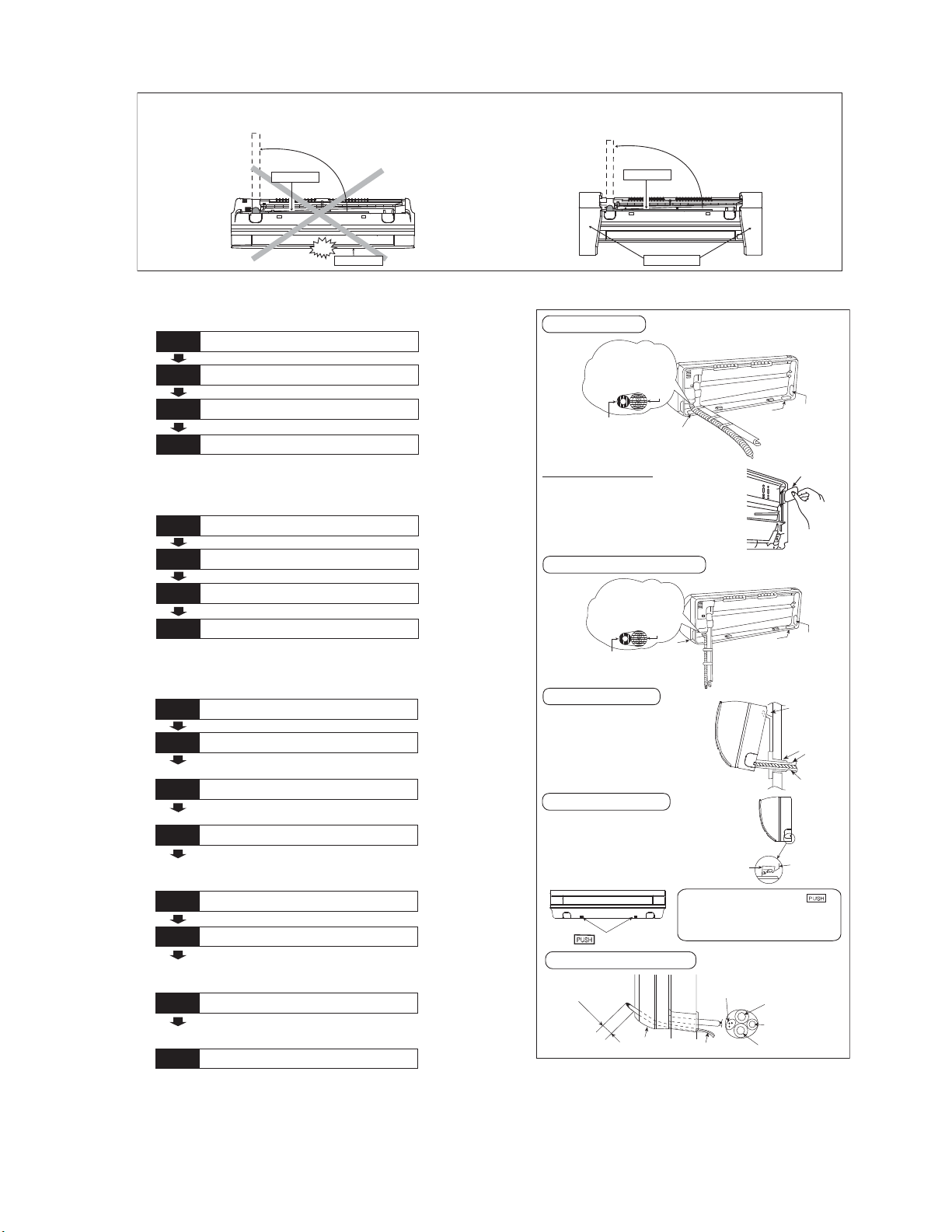
11.2.3 Indoor Unit Installation
Do not turn over the u nit without it’s shock absorber dur ing pull out the piping.
It may cause intake grille damage.
Use shock absorber during pull out the piping to protect the intake grille from damage.
p
u
l
l
o
u
t
t
h
e
p
i
p
i
n
g
Piping
Piping
p
u
l
l
o
u
t
t
h
e
p
i
p
i
n
g
PUSH PUSH
Intake grille
11.2.3.1 For the right rear piping
Step-1
Step-2
Step-3
Step-4
Pull out the Indoor piping
Install the Indoor Unit
Secure the Indoor Unit
Insert the connection cable
11.2.3.2 For the right bottom piping
Step-1
Step-2
Step-3
Step-4
Pull out the Indoor piping
Install the Indoor Unit
Insert the connection cable
Secure the Indoor Unit
11.2.3.3 For the embedded piping
Shock absorber
Right Rear piping
Tap e i t w it h
piping in a positi on as
mentioned i n
Fig. below.
Piping
Drain
hose
Cover for the
bottom piping
How to keep the cover
In case of the cover is cut, keep the
cover at the rear of chassis as shown
in the illustration for future
reinstallation.
(Left and 2 bottom covers for piping.)
Right and Right Bottom piping
Tape it with piping in a
position as mentione d
in Fig. below.
Piping
Drain hose
Cover for
the right
piping
PUSH PUSH
Cover for the
bottom piping
Cover for pi ping
Cover for the
bottom piping
Cover
for the
left
piping
Cover for
the left
piping
Replace the drain hose
Step-1
Bend the embedded piping
Step-2
• Use a spring bender or equivalent to bend the
piping so that the piping is not crushed.
Pull the connection cable into Indoor Unit
Step-3
• The inside and outside connection cable can be
connected without rem oving the front grille.
Step-4
Step-5
Step-6
Step-7
Step-8
Cut and flare the embedded piping
• When determining the dimensions of the piping,
slide the unit all the way to the left on the installation
plate.
• Refer to the section “Cutting and flaring the piping”.
Install the Indoor Unit
Connect the piping
• Please refer to “Connecting the piping” column in
outdoor unit section. (Below steps are done after
connecting the outdoor piping and gas-leakage
confirmation.)
Insulate and finish the piping
• Please refer to “Insulation of piping connection”
column as mentioned in indoor/outdoor unit
installation.
Secure the Indoor Unit
Install the indoor unit
Hook the indoor unit onto the upper
portion of installation plate. (Engage
the indoor unit with the upper edge
of the installation plate). Ensure the
hooks are properly seated on the
installation plate by moving it in left
and right.
Indoor unit
Secure the Indoor Unit
1. Press the lower left and right side
of the unit against the installation
plate until hooks engages with their
slot (sound click).
k
m
r
a
ni
g
Unit’s
hook
To take out the uni t, push the
marking at the bottom unit, and pull it
slightly towards you to disengage the
hooks from the unit.
Insert the connection cable
A
2
b
3
o
/
(
4
u
7
"
t
0
-
-
3
8
5
0mm
/
3
2
"
)
s can be used for left rear piping and bottom
(Thi
Guide
surface
Connection
cable
Connection cable
Gas side
piping
Liquid side
piping
Drain hose
piping also.)
Hooks at
installation
plate
Sleeve for
piping hole
Piping
Drain hose
Installation
plate
35
Page 5

Replace the drain hose
Rear view for left piping installation
Drain cap
How to pull the piping and drain hose out, in case of embedded piping.
•
Drain hose
Apply putty or
caulking material
to seal the wall
opening.
PVC tube for
drain hose (VP-20)
PVC tube
for dr ain
hose
M
"
16
/
9
PVC tube (VP-65) for piping
More than 27
(700 mm)
and connection cable
PVC tube for drain hose (VP-30)
Indoor unit
15
3
/16"(100mm)
Connection
cable
Adjust the piping slightly downwards.
)
m
m
n
0
ha
t
(95
"
2
ore
3
/
3
1
7
3
Connection
cable
Piping
n
a
h
t
e
r
o
M
"
1/2
18
Cable
Piping
Drain hose
)
m
m
0
7
4
(
from m ain unit
Drain hose
Connection
°
5
4
cable
More than 37
(950 mm)
Cable
13
/32"
Piping
Drain hose
Sleeve for pipin g hole
How to insert the connection cable and drain hose
•
inthecaseofleftpiping.
Drain
hose
Piping
(For right piping, follow the same procedure)
Drain hose adapter
Join indoor drain hose to 3/4" (20 mm) nominal PVC pipe size
•
by using drain hose adapter
Remarks :
Make sure indoor unit drain hose & 3/4" (20 mm) nominal PVC pipe
are fully inserted to drain hose adapter
9 usage
when necessary.
9
9
.
11.2.4 Connect the Cable to the Indoor Unit
1. The inside and outside connection cable can
be co
nnected without removing the front grille.
Unscrew the conduit cove
2.
connector to conduit cover with lock nut, then
se
cure it against chassi
3.
Connection cable between indoor un
r unit should be UL listed or
outdoo
approved 4 condu
in accordan
Connection cable between indoor un
4.
ctor wires minimum AWG1
ce with local electric code
outdoor unit should be UL listed or CSA
approved 4 condu
in accordan
ctor wires minimum AWG1
ce with local electric code
o Ensure the colour of wires of outdoor unit
and termi
indoo
Terminals on the indoor unit 1 2 3
Colour of wires (connection cable)
T erminals on the outdoor unit 1 2 3
This equipment must be properly earthed.
nal number are the same as t
r's repec
tively.
WARNING
r and fix the conduit
s.
it and
CSA
6
s.
it and
6
s.
he
Indoor unit
drain hose
Close join by Vinyl Tape ( )
Drain hose adapter
3/4" (20 mm) nominal PVC pipe
- Install incline downward more than 1°
- Apply PVC glue at the join.
9
o Earth lead wire shall be Yellow/Green
(Y/G) in colou
r and shall be longer than
other lead wires as shown in the figure fo
electrical safety in case of the slipping.
Conduit
Connector
Conduit
Cover
Lock Nut
Chassis
Rear Side of Indoor Unit
Ter m i n a l
Board
Indoor and
outdoor
connection
cable
123
Holder
Earth Wire
longer than
others AC
wires for
safety
reason
r
36
Page 6

11.2.5 Wiring Stripping and connecting requirement
1
mproperfla
rin
g
No loose strand
when inserted
(10±1 mm)
13/32" ± 1/16"
Wire stri ppin g
Indoor/outdoor
connection
terminal board
7
/32"
(5 mm)
or more
(gap between wires)
Conductor
fully inserted
ACCEPT PROHIBITED PROHIBITED
Conductor
over inserted
Conductor not
fully inserted
RISK OF FIRE
JOINING OF WIRES
WARNING
MAY CAUSE
OVER HEATING
AND FIRE.
OR
Do not joint wires
OR
OR
Use complete wire without joining.
Use approved socket and plug with earth pin.
Wire connection in this area must follow to
national wiring rules.
11.2.5.1 Cutting and flaring the piping
1 Please cut using pipe cutter and then remove the burrs.
2 Remove the burrs by using reamer. If burrs are not removed, gas leakage may be caused. Turn the piping
end down to avoid the metal powder entering the pipe.
3 Please make flare after inserting the flare nut onto the copper pipes.
.Tocut
Pipe
Poin t dow n
2. To remove burrs
Reamer
Bar
Clamp handle
3. To flare
Handle
Yo k e
Core
Red arrow mark
Bar
1
0–
/32"
(0-0.5 mm)
Copper
pipe
I
Inclined Surface
When properly flared, the internal surface of the
flare will evenly shine and be of even thickness.
Since the flare part comes into contact with the
connections, carefully check the flare finish.
damaged
Cracked U neven
thickness
37
Page 7

11.3 Outdoor Unit
S
11.3.1 Install the Outdoor Unit
After selecting the best location, start installation according to indoor/outdoor unit installation diagram.
1 Fix the unit on concrete or rigid frame firmly and horizontally by bolt nut (ø13/32" (ø10 mm)).
2 When installing at roof, please consider strong wind and earthqua
Please fa
sten the installation stand firmly with bolt or nails.
ke.
AB
C
D
11.3.2 Connect the Piping
11.3.2.1 Connecting the piping to
indoor
Please make flare after inserting flare nut (locate at
joint portion, of tube assembly) onto the copper pipe.
(In case of using long piping)
Connect the piping
Align the center of piping and suffici
the flare nut
with fingers.
Further tighten the flare nut with torque wren
cified torque as stated in the table.
spe
ently tighten
ch in
11.3.2.2 Connecting the piping to
outdoor
Decide piping length and then cut by using pipe cutter.
Remove burrs from cut edge.
Make flare after inserting the flare nut (locate at valve)
onto the copper pipe.
Align center of piping to valves and then tighten with
torque wrench to the specified torque as stated in the
table.
Model A B C D
22-7/16
"
E9RKUA, E12RKUA
Do not over tighten, over tightening may cause gas leakage.
Piping size Torque
1/4" (6.35 mm) 13.3 Ibf.ft [18 N•m (1.8 kgf•m)]
3/8” (9.52 mm) 31.0 Ibf.ft [42 N•m (4.3 kgf•m)]
1/2" (12.7 mm) 40.6 Ibf.ft [55 N•m (5.6 kgf•m)]
5/8” (15.88 mm) 47.9 Ibf.ft [65 N•m (6.6 kgf•m)]
3/4" (19.05 mm) 73.8 Ibf.ft [100 N•m (10.2 kgf•m)]
(570 mm)
panner
or Wrench
4-1/8"
(105 mm)
23/32"
(18.5 mm)
Torq u e
wrench
12-19/32
(320 mm)
"
38
Page 8

11.3.2.3 Connecting the piping to outdoor multi
Decide piping length and then cut by using pipe cutter. Remove burrs from cut edge.
Make flare after inserting the flare nut (locate at valve) onto the copper pipe.
Align center of piping to valve and then tighten with torque wrench to the specified torque as stated in the table.
Male side Female side
(Adjustable Wrench)
Male side
(Adjustable Wrench)
Torque Wrench for Flare
Nut and Pipe Size Reducer
Hall Union
(Auxiliary pipe)
Wrench
(Auxiliary pipe)
Wrench
Hall Union
Pack ing
Flare Nut
(Connection pipe)
Torque Wrench for Flare Nut
Pipe Size
Reducer
Applicable to
Liquid and Gas side of
CS-E9RKUAW
Liquid side of
CS-E12RKUAW
Flare Nut
Female side
(Connection pipe)
Applicable to
Gas side of
CS-E12RKUAW
11.3.2.4 Gas Leak Checking
Pressure test to system to 400 PSIG with dry nitrogen, in stages. Thoroughly leak check the system.
If the pressure holds, release the nitrogen and proceed to section 11.3.3.
11.3.3 Evacuation of the equipment
WHEN INSTALLING AN AIR CONDITIONER, BE SURE TO EVACUATE THE AIR INSIDE THE INDOOR UNIT AND
PIPES in the following procedures.
Indoor unit
Liquid side
Two-way valve
Outdoor unit
Close
Gas side
Three-way valve
Close
CLOSE
Vacuu m
pump
OPEN
Hi
Lo
1. Connect a charging hose with a push pin to the Low side of a charging set and the service port of the 3-way
valve.
Connect the micron gauge between vacuum pump and service port of outdoor un
2.
Turn on the power switch of the vacuum pump and make sure that connect digital micron gauge and to pull
3.
its.
down to a value of 500 microns.
4.
To make sure micron gauge a value 500 microns and close the low side valve of the charging set and turn of
the vacuum pump.
Disconnect the vacuum pump house from the service
5.
6.
Tighten the service port caps of the 3-way valve at a torque of 13.3 Ibf.ft (18 N•m) with a torque wrench.
Remove the valve caps of both of the 2-way valve and 3-way valve. Position both of the valves to “Op
7.
port of the 3-way valve.
en”
using a hexagonal wrench (5/32" (4 mm)).
8.
Mount valve caps onto the 2-way valve and the 3-wa
Be sure to check for gas leakage.
o
If micron gauge value does not descend 500 microns, take the following measures:
•
- If the leak stops when the piping connections are tightened further, continue working from step3.
- If the leak does not stop when the connections are retightened, repair location of leak.
- Do not release refrigerant during piping work for installation and reinstallation.
- Be careful with the liquid refrigerant, it may cause frostbite.
y valve.
f
39
Page 9

11.3.3.1 Connect the Cable to the Outdoor Unit
o
pPa
n
C
C
r
U
r
U
1. Remove Top panel.
2.
Remove Control Board Cover (Resin and
Metal).
emove Plugs
R
3.
4. Fix the conduit connectors to the knocko
hole
s with lock-nuts, then secure them agains
the side p
All wires pass through conduits.
5.
6. Connection cable between indoor un
r unit should be UL listed or
outdoo
approved 4 conductor wires minimum AWG16
in accordan
Wire connection to the power su
7.
30V 60Hz) through circuit breake
(208/2
o
Connect the UL liste
wire
board, and co
wires to ELCB / GFCI.
8. Connect the power supply cord a
nection cable between indoor un
con
outdoo
r unit according to the diagram below.
.
ane
l.
ce with local electric code
d or CSA approved
s minimum AWG14 to
nne
ct the other end of the
ut
t
it and
CSA
s.
pply
r.
the terminal
nd
it and
Control Board
Metal Cover
ontrol Board
over (Resin)
Connectors
T
el
Power
Supply
Wires
Lock Nuts
Knockout
Holes
Plugs
Side Panel
nit
Indoo
1
2
3
9.
Secure the wire onto the control board wi
the holde
After completing wiring connections, re
10.
the cont
the top panel
sc
r (clamper).
rol board cover (Metal and Resi
to the original position
rews.
208/230V min AWG16
208/230V min AWG16
208/230V min AWG16
Grounding wire min AWG16
* Ensure all connecting wire
between indoor unit and
outdoor unit and power supply
cord are installed in individual
conduit.
with the
11. For wire stripping and connection requirement,
refer to instruction 11.2.5 of indoor unit.
WARNING
This equipment must be properly earthed.
Earth lead wire shall be Yellow/Green
colo
ur and shall be longer than other lead wire
wn in the figure for electrical safe
as sho
(Y/G) in
ty in case
of the slipping.
th
attach
n) and
s
Outdoo
1
2
3
L1
L2
nit
lanimreTlanimreT
Disconnect
Switch
Field supply
Grounding wire
Earth wire
longer than
others AC
wires for
safety
reason
Power Supply
Single Phase
208/230V 60Hz
min AWG14
L1 L2 1 2 3
Power
supply
cord
Indoor &
outdoor
connection
cable
Ter m i n a l
Board
Earth wire
longer than
others AC
wires for
safety
reason
Holder
11.3.3.2 Piping Insulation
1. Please carry out insulation at pipe connection portion as mentioned in Indoor/Outdoor Unit Installation
Diag
ram. Please wrap the insulated piping end to prevent water from going inside the piping.
If drain hose or connecting piping is in the room (where dew may form), please increase the insulation
2.
using POLY-E FOAM with thickness 1/4" (6 mm) or above.
40
by
Page 10

12. Installation Instruction (E18RK and E24RK)
ferentway
12.1 Select the Best Location
12.1.1 Indoor Unit
Do not install the unit in excessive oil fume area
such as kitchen, workshop and etc.
ed.
level.
Max.
Piping
Length
100.0 f t
(
30.5 m)
steam
ng the air
into
oor unit
ion from
wall,
for
ould be
Additional
Refrigerant
0.3 oz/ft
(
25 g/m)
Piping
Length
for add.
32.8 ft
(
10 m)
There should not be any heat source or
near the unit.
There should not be any obstacles blocki
circulation.
A place where air circulation in the room is good.
A place where drainage can be easily done.
A place where noise prevention is taken
c
onsiderat
Do not install the unit near the door way.
ion.
Ensure the spaces indicated by arrows from the
wall, ceili
ng, fence or other obstacles.
Recommended installation height for ind
shall be at least 8 ft (2.4 m).
12.1.2 Outdoor Unit
If an awning is built over the unit to prevent direct
sunli
ght or rain, be careful that heat radiat
the con
There should not be any animal or plant which
coul
Keep the spaces indicated by arrows from
ceiling, fence or other obstacles.
Do not place any obstacles
sho
If piping length is over the [piping length
addition
adde
Recommended installation height for outdoor un
sho
Model
E18RKUA
E24RKUA
denser is not obstructed.
d be affected by hot air discharg
which may cause a
rt circuit of the discharged air.
al gas], additional refrigerant sh
d as shown in the tabl
e.
uld be above the seasonal snow
Capacity
(Btu/h)
17200
24000
Piping s ize
Gas Liquid
1/2"
(
12.7 mm)
5/8"
(
15.88 m m)
1/4"
(
6.35 mm)
Std.
Length
24.6 ft
(
7.5 m)
Max.
Elevation
49.2 ft
(
15 m)
Piping
Length
(
Min.
9.8 ft
3m)
gas
12.1.3 Indoor/Outdoor Unit Installation
Diagram
Piping direction Attention not to bend
Right
Rear
Right
Left
Rear
bottom
131/32"
(50 mm)
or more
Insulation of pi ping connections
• Carr y out insulation after
checking for gas leaks and
secure with vinyl tape.
Attaching the remote control holder to the wall
Remote control holder fixingscrews
Remote
control
it
Left bottom
(Left and ri ght ar e ident ical)
3
It is advisable to
avoid m ore than 2
blockage directions.
For better ventilation
& multiple-outdoor
installation, please
consult autho r ized
dealer/specialist.
• This illustration is for
explanation purposes only.
The indoor unit will actually face
adif
up drai n hose(Front side)
Left
"
16
/
9
2
Floor / Grade level
Ú
Vinyl tape
6
Remote control holder
3
1
(
5
1
0
0
o
m
r
mo
r
e
3
100
(
.
"
)
6
1
m
/
e
5
r
m
1
o
0
m
0
r
1
(
o
(
o
Installation parts you
should purchase (Ú)
Installation plate 1
Bushing-Sleeve (
Sleeve (
Putty (
(Gum Type Sealer)
Bend the pi pe a s
closely on the wall as
possible, but be careful
that it doesn’t break.
Vinyl tape (wide) (Ú)
• Apply after carrying
out a drainage test.
• To carry out the
drainage test,
remove the air filters
and pou r water into
the heat exchanger.
Saddle (
Conduit
(Power supply cord (
Conduit
(Connection cable)
Liquid side pi ping (
Gas side piping (
Additional drain hose
1
Control Board cover
1
1
3
3
0
/
0mm)
1
6
r
"
mo
r
e
Ú
)
Ú
)
Ú
)
Ú
)
Ú
))
Ú
)
Ú
)
e
m)
65 m
or mor
(
4m)
ore
2.
(
rm
o
8ft
5
/
1
6
"
m)
"
8
/
3
m
9
0
m
r
o
3
)
m
e
r
o
Example: For E18RKUA
If the unit is installed at 41 ft (12.5 m) distance, the
quantity of additional refrigerant should be 2.46 oz
(62.5 g) .... (41 - 32.8) ft x 0.3 oz/ft = 2.46 oz.
((12.5 - 10) m x 25 g/m = 62.5 g).
41
Page 11

12.2 Indoor Unit
12.2.1 How to Fix Installation Plate
The mounting wall shall be strong and solid enough to prevent it from the vibration.
Wall
Measuring
Ta p e
E18RKUA, E24RKUA
917/32"
(241.5 mm)
Model
51/16"
(128 mm)
More than 1
Indoor unit
2 screw
3 4
6
5
123 4 56
7
/32"
23
(590 mm)
51/16" (128 mm)
For best strength of
INDOOR unit installation,
it is highly recommended
to locate “
as shown.
37/32"
(82 mm)
Wall
More than
2
Installation plate 1
” at 5 position
Dimension
217/32"
(539 mm)
(532 m m )
2015/16"
More than 1
621/32"
(169 mm)
The center of installation plate should be at more than c at right and left of the wall.
The distance from installation plate edge to ceiling should more than d.
From installation plate left edge to unit’s left side is e.
From installation plate right edge to unit’s right side is f.
B : For left side piping, piping connection for liquid should be about g from this line.
ƻ
: For left side piping, piping connection for gas should be about h from this line.
17
9
/32”
(241.5 mm)
1
5
/16"
(128 mm)
85/8"
(219 mm)
Wall
1 Mount the installation plate on the wall with 5 screws or more (at least 5 screws).
(If mounting the unit on the concrete wall, consider using anchor bolts.)
o Always mount the installation plate horizontally by aligning the marking-off line with the thread and us
a level gaug
e.
2 Drill the piping plate hole with ø2 3/4" (ø70 mm) hole-core drill.
o Line according to the left and right side of the installation plate. The meeting point of the extended lin
the cente
above. The h
hole re
o
Drill the piping hole at either the right or the left and the hole should be slightly slanting to the outdoo
r of the hole. Another method is by putting measuring tape at position as sh
ole center is obtained by measuring the distance namely 5 1/16" (128 mm) fo
vely.
specti
side.
12.2.2 To Drill a Hole in the Wall and
Install a Sleeve of Piping
1 Insert the piping sleeve to the hole.
2 Fix the bushing to the sleeve.
3 Cut the sleeve until it extrudes about 19/32"
(15 mm) from the wall.
CAUTION
When the wall is hollow, please be sure
to use the sleeve for tube assembly to
prevent dangers caused by mice biting
the connection cable.
4 Finish by sealing the sleeve with putty or
caulking compound at the final stage.
Indoor
Sleeve for
tube
assembly
3
ø2
/4" (ø70 mm)
through hole
Wall
Outdoor
19
Putty or caulking compound
own in the diagram
r left and right
/32" (15 mm)
Approx.7/32"-9/32"
(5 - 7 mm)
Bushing for tube
assembly
ing
e is
r
42
Page 12

12.2.3 Indoor Unit Installation
Do not turn over the unit without it’s shock absorber dur ing pull out the piping.
It may cause intake grille damage.
Use shock absorber during pull out the piping to protect the intake grille from damage.
p
u
l
l
o
u
t
t
h
e
p
i
p
i
n
g
Piping
Piping
p
u
l
l
o
u
t
t
h
e
p
i
p
i
n
g
PUSH PUSH
Intake grille
12.2.3.1 For the right rear piping
Step-1
Step-2
Step-3
Step-4
Pull out the Indoor piping
Install the Indoor Unit
Secure the Indoor Unit
Insert the connection cable
12.2.3.2 For the right bottom piping
Step-1
Step-2
Step-3
Step-4
Pull out the Indoor piping
Install the Indoor Unit
Insert the connection cable
Secure the Indoor Unit
12.2.3.3 For the embedded piping
Shock absorber
Right Rear piping
Tap e i t w i th
piping in a posit ion as
mentioned i n
Fig. below.
Piping
Drain
hose
Cover for the
bottom piping
How to keep the cover
In case of the cover is cut, keep the
cover at the rear of chassis as shown
in the illustration for future
reinstallation.
(Left and 2 bottom covers for piping.)
Right and Right Bottom piping
Tape it with piping in a
position as mentio ned
in Fig. below.
Piping
Drain hose
Cover for
the right
piping
PUSH PUSH
Cover for the
bottom piping
Cover for piping
Cover for the
bottom piping
Cover
for the
left
piping
Cover for
the left
piping
Replace the drain hose
Step-1
Bend the embedded piping
Step-2
• Use a spring bender or equivalent to bend the
piping so that the piping is not crushed.
Pull the connection cable into Indoor Unit
Step-3
• The inside and outside connection cable can be
connected without rem oving the front grille.
Step-4
Step-5
Step-6
Step-7
Step-8
Cut and flare the embedded piping
• Whe n determining the dimensions of the piping,
slide the unit all the way to the left on the installation
plate.
• Refer to the section “Cutting and flaring the piping”.
Install the Indoor Unit
Connect the piping
• Please refer to “Connecting the piping” colum n in
outdoor unit section. (Below steps are done after
connecting the outdoor piping and gas-leakage
confirmation.)
Insulate and finish the piping
• Please refer to “Piping and finishing” column of
outdoor section and “Insulation of piping
connection” column as m entioned in indoor/outdoor
unit installation.
Secure the Indoor Unit
Install the indoor unit
Hook the indoor unit onto the upper
portion of installation plate. (Engage
the indoor unit with the upper edge
of the installation plate). Ensure the
hooks are properly seated on the
installation plate by moving it in left
and right.
Indoor unit
Secure the Indoor Unit
1. Press the lower left and right side
of the unit against the installation
plate until hooks engages with their
slot (sound click).
k
m
r
a
ni
g
Unit’s
hook
To take out the uni t, push the
marking at the bottom unit, and pull it
slightly towards you to disengage the
hooks from the unit.
Insert the connection cable
A
2
b
3
o
/
(
4
u
7
"
t
0
-
-
3
8
0mm)
5
/
3
2
"
Guide
surface
s can be used for left rear piping and bottom
(Thi
Connection
cable
Connection cable
Gas side
piping
Liquid side
piping
Drain hose
piping also.)
Hooks at
installation
plate
Sleeve for
piping hole
Piping
Drain hose
Installation
plate
43
Page 13

Replace the drain hose
Rear view for left piping installation
Drain cap
How to pull the piping and drain hose out, in case of embedded piping.
•
Drain hose
Apply putty or
caulking material
to seal the wall
opening.
hose (VP-20)
PVC tube
for drain
hose
"
16
/
9
More than 27
(700 mm)
o
M
45
1
PVC tube (VP-65) for piping
and connection cable
PVC tube for drain hose (VP-30)PVC tube for drain
Indoor unit
227/32" (72 mm)
Connection
cable
Adjust the piping slightly downwards.
an
h
t
re
"
2
)
3
/
9
m
m
0
15
(1
Connection cable
Piping
n
a
h
t
e
r
)
o
m
M
"
2
1
/
8
Cable
Piping
Drain hose
m
0
7
4
(
from main unit
Drain hose
Connection
°
5
4
cable
More than 45
(1150 m m)
Cable
9
/32"
Piping
Drain hose
Sleeve for piping hole
How to insert the connection cable and drain hose
•
inthecaseofleftpiping.
Drain
hose
Piping
(For right piping, follow the same procedure)
Drain hose adapter
Join indoor drain hose to 3/4" (20 mm) nominal PVC pipe size
•
by using drain hose adapter
Remarks :
Make sure indoor unit drain hose & 3/4" (20 mm) nominal PVC pipe
are fully inserted to drain hose adapter
9 usage
when necessary.
9
9
.
12.2.4 Connect the Cable to the Indoor Unit
1. The inside and outside connection cable can
be co
nnected without removing the front grille.
Unscrew the conduit cove
2.
nector to conduit cove
con
se
cure it against chassi
Connecting wire between indoor unit an
3.
r unit should be UL listed or
outdoo
approved 4 conductor wires minimum AWG16
in accordan
Ensure the colour of wires of outdoor un
o
ce with local electric code
and terminal number are the same as the
indoo
r's repec
Terminals on the indoor unit 1 2 3
Colour of wires (Connecting wire)
Terminals on the outdoor unit 1 2 3
This equipment must be properly earthed.
o
Earth lead wire shall be
(Y/G) in colou
tively.
WARNING
r and shall be longer than
other lead wires as shown in the figure fo
electri
cal safety in case of the slipping.
r and fix the conduit
r with lock nut, then
s.
d
CSA
s.
it
Yellow/Green
r
Indoor unit
drain hose
Close join by Vinyl Tape ( )
Drain hose adapter
3/4" (20 mm) nominal PVC pipe
- Install incline downward m ore than 1 °
- Apply PVC glue at the join.
Conduit
Connector
Lock Nut
Rear Side of Indoor Unit
123
Indoor and
outdoor
connection
cable
Holder
Ter m i n a l
Board
Earth Wire
longer than
others AC
wires for
safety
reason
9
Conduit
Cover
Chassis
44
Page 14

12.2.5 Wiring Stripping and connecting requirement
1
mproperfla
rin
g
No loose strand
when inserted
(10±1 mm)
13/32" ± 1/16"
Wire stri pping
Indoor/outdoor
connection
terminal board
7
/32"
(5 mm)
or more
(gap between wires)
Conductor
fully inserted
ACCEPT PROHIBITED PROHIBITED
Conductor
over inser ted
Conductor not
fully inserted
RISK OF FIRE
JOINING OF WIRES
WARNING
MAY CAUSE
OVER HEATING
AND FIRE.
OR
Do not joint wires
OR
OR
Use complete wire without joining.
Use approved socket and plug with earth pin.
Wire connection in this area must follow to
national wiring rules.
12.2.5.1 Cutting and flaring the piping
1 Please cut using pipe cutter and then remove the burrs.
2 Remove the burrs by using reamer. If burrs are not removed, gas leakage may be caused. Turn the piping
end down to avoid the metal powder entering the pipe.
3 Please make flare after inserting the flare nut onto the copper pipes.
.Tocut
Pipe
Poin t dow n
2. To remove burrs
Reamer
Bar
Clamp handle
3. To flare
Handle
Yo k e
Core
Red arrow mark
Bar
1
/32"
0–
(0-0.5 mm)
Copper
pipe
I
Inclined Surface
When properly flared, the internal surface of the
flare will evenly shine and be of even thickness.
Since the flare part comes into contact with the
connections, carefully check the flare finish.
damaged
Cracked U neven
thickness
45
Page 15

12.3 Outdoor Unit
S
12.3.1 Install the Outdoor Unit
After selecting the best location, start installation according to indoor/outdoor unit installation diagram.
1 Fix the unit on concrete or rigid frame firmly and horizontally by bolt nut ø13/32" (ø10 mm).
2 When installing at roof, please consider strong wind and earthqua
Please fa
sten the installation stand firmly with bolt or nails.
ke.
AB
C
D
12.3.2 Connect the Piping
12.3.2.1 Connecting the piping to
indoor
Please make flare after inserting flare nut (locate at
joint portion, of tube assembly) onto the copper pipe.
(In case of using long piping)
Connect the piping
Align the center of piping and suffici
the flare nut
with fingers.
Further tighten the flare nut with torque wren
cified torque as stated in
spe
the table.
ently tighten
ch in
12.3.2.2 Connecting the piping to
outdoor
Decide piping length and then cut by using pipe cutter.
Remove burrs from cut edge.
Make flare after inserting the flare nut (locate at valve)
onto the copper pipe.
Align center of piping to valves and then tighten with
torque wrench to the specified torque as stated in the
table.
Model A B C D
E18RKUA,
E24RKUA
Do not over tighten, over tightening may cause gas leakage.
Piping size Torque
1/4" (6.35 mm) 13.3 Ibf.ft [18 N•m (1.8 kgf•m)]
3/8” (9.52 mm) 31.0 Ibf.ft [42 N•m (4.3 kgf•m)]
1/2" (12.7 mm) 40.6 Ibf.ft [55 N•m (5.6 kgf•m)]
5/8” (15.88 mm) 47.9 Ibf.ft [65 N•m (6.6 kgf•m)]
3/4" (19.05 mm) 73.8 Ibf.ft [100 N•m (10.2 kgf•m)]
24-1/8"
(613 mm)
panner
or Wrench
5 5/32"
(131 mm)
(16 mm)
Torq u e
wrench
5/8"
14 3/16"
(360.5 mm)
46
Page 16

12.3.2.3 Connecting the piping to outdoor multi
Decide piping length and then cut by using pipe cutter. Remove burrs from cut edge.
Make flare after inserting the flare nut (locate at valve) onto the copper pipe.
Align center of piping to valve and then tighten with torque wrench to the specified torque as stated in the table.
Male side Female side
(Adjustable Wrench)
Male side
(Adjustable Wrench)
Torque Wrench for Flar e
Nut and Pipe Size Reducer
Hall Union
(Auxiliary pipe)
Wrench
(Auxiliary pipe)
Wrench
Hall Union
Pack ing
Flare Nut
Tor q u e W r e n c h
for Flare Nu t
(Connection pipe)
Pipe Size
Reducer
Applicable to
Liquid side of
CS-E18RKUA
CS-E24RKUA
Flare Nut
Female side
(Connection pipe)
Applicable to
Gas side of
CS-E18RKUA
CS-E24RKUA
12.3.2.4 Gas Leak Checking
Pressure test to system to 400 PSIG with dry nitrogen, in stages. Thoroughly leak check the system.
If the pressure holds, release the nitrogen and proceed to section 12.3.3.
12.3.3 Evacuation of the equipment
Indoor unit
Liquid side
Gas side
Two-way valve
Close
Outdoor unit
Three-way valve
Close
Vac uu m
pump
1.
Connect a charging hose with a push pin to the Low side of a charging set and the service port of the 3-wa
valve.
Connect the micron gauge between vacuum pump and service port of outdoor un
2.
Turn on the power switch of the vacuum pump and make sure that connect digital micron gauge
3.
its.
and to pull
down to a value of 500 microns.
To make sure micron gauge a value 500 microns and close the low side valve of the charging set and turn of
4.
the vacuum pump.
5. Disconnect the vacuum pump house from the service
Tighten the service port caps of the 3-way valve at a torque of 13.3 Ibf•ft (18 N•m) with a torque wrench.
6.
Remove the valve caps of both of the 2-way valve and 3-way valve. Position both of the valves to “Op
7.
usin
g a hexagonal wrench (5/32" (4 mm)).
Mount valve caps onto the 2-way valve and the 3-wa
8.
Be sure to check for gas leakage.
o
If micron gauge value does not descend 500 microns, take the following measures:
•
- If the leak stops when the piping connections are tightened further, continue working from step3.
- If the leak does not stop when the connections are retightened, repair location of leak.
- Do not release refrigerant during piping work for installation and reinstallation.
- Be careful with the liquid refrigerant, it may cause frostbite.
port of the 3-way valve.
y valve.
y
f
en”
47
Page 17

12.3.3.1 Connect the Cable to the Outdoor Unit
r
U
r
U
Con
n
n
gWires
1. Remove control board cover (Resin and Metal).
2. Remove particular plate.
3. Remove plugs.
4. Fix the conduit connectors to the knockout holes with lock-nuts, then secure them against the side panel.
5. All wires pass through conduits & particular plate’s opening hole.
6. Connecting wire between indoor unit and outdoor unit should be UL listed or CSA approved 4 conductor
wires minimum AWG16 in accordance with local electric codes.
7. Wire connection to the power supply (208/230V 60Hz) through circuit breaker.
o Connect the UL listed or CSA approved wires minimum AWG12 to the terminal board, and connect the
other end of the wires to ELCB / GFCI.
8. Connect the power supply cord and connecting wire between indoor unit and outdoor unit according to the
diagram below.
nit
Indoo
1
2
3
208/230V min AWG16
208/230V min AWG16
208/230V min AWG16
Grounding wire min AWG16
* Ensure all connecting wire
between indoor unit and
outdoor unit and power supply
cord are installed in individual
conduit.
9. Secure the wire onto the control board with the holder (clamper).
10. After completing wiring connections, reattach the control board cover (Metal and Resin) and the top panel to
the original position with the screws.
11. For wire stripping and connection requirement, refer to instruction 12.2.5 of indoor unit.
WARNING
This equipment must be properly earthed.
Earth lead wire shall be Yellow/Green (Y/G) in colour and longer than other lead wires for electrical safety in case
of the slipping.
Front Panel
Particular
Plate
Lock Nuts
ecti
Control Board
Cover (Metal)
Control Board
Cover (Resin)
Outdoo
TerminalTerminal
Earth wire
longer than
others
AC wi res
for safety
reason
1
2
3
L1
L2
Ter m i n a l
Board
nit
Disconnect
Switch
Field supply
Grounding wire
Power Supply
Single Phase
208/230V 60Hz
min AWG12
Te r m i n a l
Board
Earth wire
longer than
others
AC wires
for s afet y
reason
HolderHolder
Knockout
Holes
Plugs
Connectors
Particular Plate’s
opening holes
Powe r
supply
cord
Indoor &
outdoor
connection
cable
12.3.3.2 Piping Insulation
1. Please carry out insulation at pipe connection portion as mentioned in Indoor/Outdoor Unit Installation
Diagram. Please wrap the insulated piping end to prevent water from going inside the piping.
2. If drain hose or connecting piping is in the room (where dew may form), please increase the insulation by
using POLY-E FOAM with thickness 1/4" (6 mm) or above.
48
 Loading...