

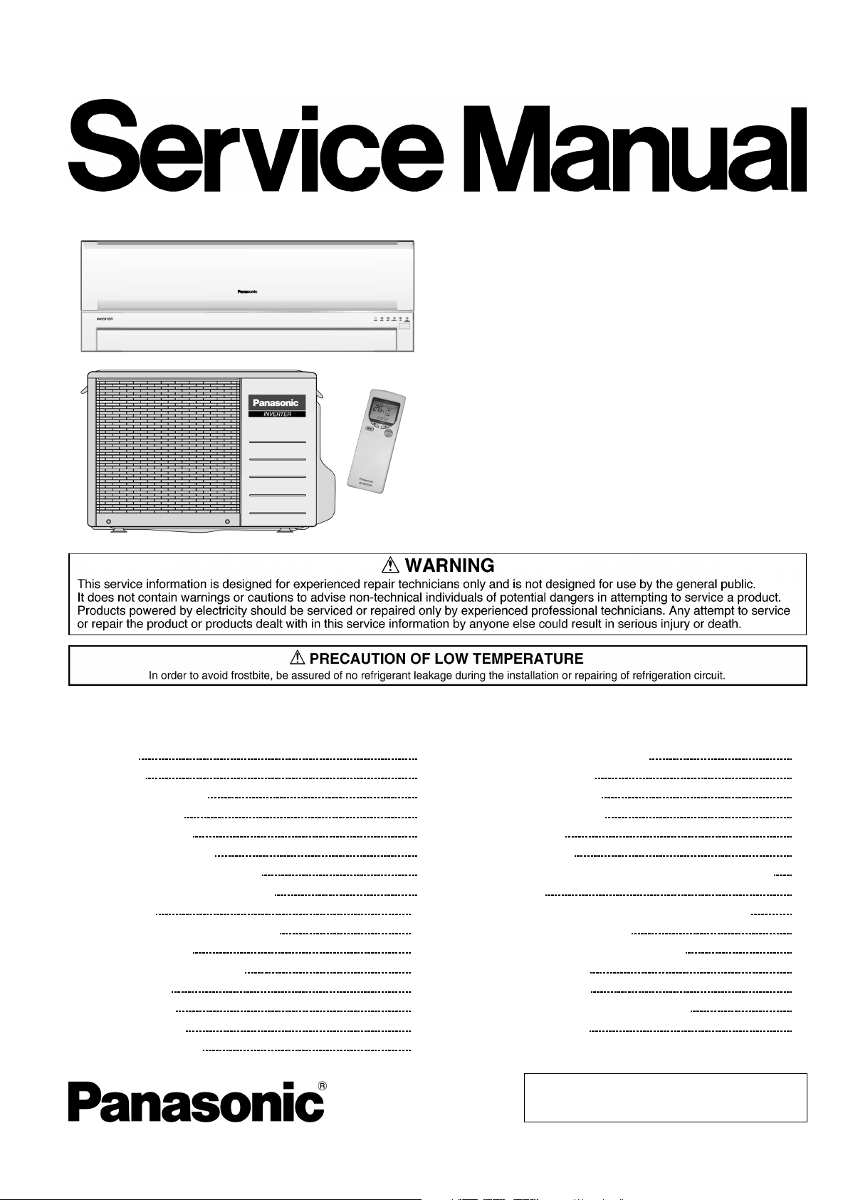
Panasonic CS-E9DKDW, CU-E9DKD, CS-E12DKDW, CU-E12DKD Service Manual
Order No: MAC0412071C2
Air Conditioner
CS-E9DKDW CU-E9DKD
CS-E12DKDW CU-E12DKD
CONTENTS
Page Page
1 Features 2
2 Functions
2.1. Remote Control
2.2. Indoor Unit
2.3. Outdoor Unit
3 Product Specifications
3.1. CS-E9DKDW CU-E9DKD
3.2. CS-E12DKDW CU-E12DKD
4 Dimensions
4.1. Indoor Unit & Remote Control
4.2. Outdoor Unit
5 Refrigeration Cycle Diagram
6 Block Diagram
7 Wiring Diagram
8 Operation Details
8.1. Basic Function
11
11
12
13
14
15
16
16
3
3
4
6
7
7
9
8.2. Protection Control Features 35
9 Operating Instructions
10 Installation Instructions
10.1. Safety Precautions
10.2. Indoor Unit
10.3. Outdoor Unit
11 Installation And Servicing Air Conditioner Using R410A
11.1. Outline
11.2. Tools For Installing/Servicing Refrigerant Piping
11.3. Refrigerant Piping Work
11.4. Installation, Transferring, Servicing
12 Servicing Information
12.1. Troubleshooting
12.2. Breakdown Self Diagnosis Function
12.3. Remote Control
© 2004 Panasonic HA Air-Conditioning (M) Sdn Bhd
(11969-T). All rights reserved. Unauthorized copying
and distribution is a violation of law.
44
50
50
53
57
61
61
62
66
68
72
72
74
76

CS-E9DKDW CU-E9DKD / CS-E12DKD W CU-E12DKD
12.4. Disassembly of Parts 77
13 Technical Data
13.1. Operation Characteristics
13.2. Sensible Capacity Chart
14 Exploded View (Indoor Unit)
14.1. CS-E9DKDW CS-E12DKDW
15 Replacement Parts List (Indoor Unit)
15.1. CS-E9DKDW CS-E12DKDW
16 Exploded View (Outdoor Unit)
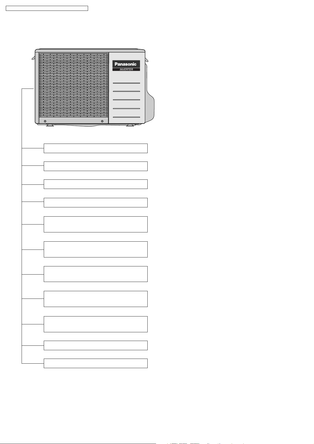
1 Features
Product
•
Four modes of operation selection
−
Powerful Mode operation
−
Delay ON Timer and OFF Timer
−
Ionizer Mode Operation
−
Quiet Mode Operation
−
Automatic air swing and manual adjusted by Remote
−
Control for horizontal and vertical airflow.
Supersonic Air Purifying System with Super Alleru-
−
Buster.
Inactive various harmful airbone elements including
allergens, viruses and bacteria.
Generated supersonic waves enhance the ability to
collect dust and dirt in the air.
16.1. CU-E9DKD CU-E12DKD 85
17 Replacement Parts List (Outdoor Unit)
80
80
82
83
83
84
84
85
17.1. CU-E9DKD CU-E12DKD
18 Electronic Circuit Diagram
18.1. Indoor Unit
18.2. Outdoor Unit
18.3. Remote Control
18.4. Print Pattern Indoor Unit Printed Circuit Board
18.5. Print Pattern Outdoor Unit Printed Circuit Board
Serviceability Improvement
•
Removable and washable Front Panel
−
Breakdown Self Diagnosis function
−
Environmental Protection
•
Non-ozone depletion substances refrigerant (R410A)
−
Quality Improvement
•
Gas leakage detection
−
Deice operation
−
Auto restart control
−
86
86
87
87
91
96
97
98
2
2 Functions
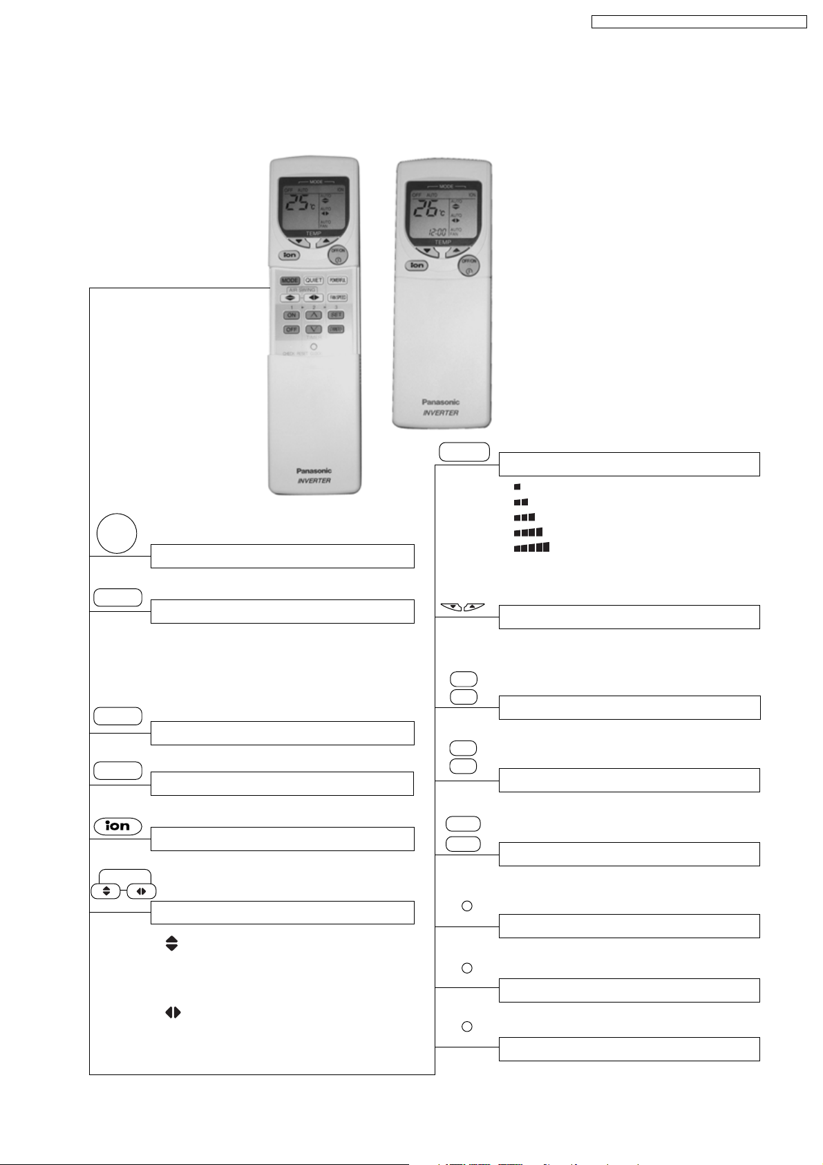
2.1. Remote Control
CS-E9DKDW CU-E9DKD / CS-E12DKD W CU-E12DKD
OFF/ON
I
MODE
POWERFUL
QUIET
AIR SWING
Operation OFF / ON
Operation Mode Selection
•
•
•
•
a
HEAT
COOL
DRY
Automatic Operation
Heating Operation
Cooling Operation
Soft Dry Operation
Powerful Mode Operation
Quiet Mode Operation OFF / ON
Ion Mode Operation OFF / ON
Airflow Direction Control
• Vertical Automatic Airflow
Direction Control and Manual
Airflow Direction Control (5
stages of adjustment).
•
Horizontal Automatic Airflow
Direction Control and Manual
Airflow Direction Control (5
stages of adjustment).
FAN SPEED
TEMP
TIMER
ON
OFF
∧
∨
SET
CANCEL
CLOCK
CHECK
RESET
Indoor Fan Speed Selection
• Low
•
•
•
•
•
AUTO
FAN
MediumMedium
Medium+
High
Automatic Fan Speed
Room Temperature Setting
• Increase or decrease set temperature
(16°C to 30°C)
Timer Operation Selection
• 24-hour, OFF / ON Real Timer Setting.
Time / Timer Setting
• Hours and minutes setting.
Timer Operation Set / Cancel
• ON Timer and OFF Timer setting and
cancellation.
Clock Setting
• Current time setting.
Check Point
• Breakdown self diagnosis function.
Reset Point
• Clear memory data.
3
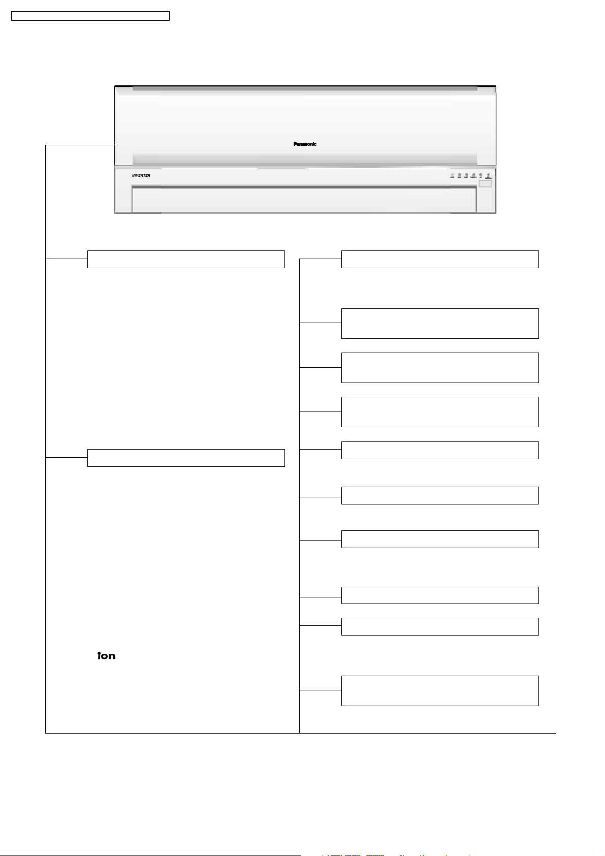
CS-E9DKDW CU-E9DKD / CS-E12DKD W CU-E12DKD
2.2. Indoor Unit
Automatic Operation Switch
• Press for < 5s to run Automatic Operation.
(Used when the remote control cannot be used.)
• Press continuously for 5s and < 8s to run
Forced Cooling Operation.
• Press continuously for 8s and < 11s to
run Forced Heating Operation.
• Press continuously for 11s and < 16s to
change different remote controlling
setting (A↔B Mode).
• Press continuously for 16s or < 21s to
switch OFF / ON Remote Control
Receiving Sound or H14 Abnormality
Detection Mode.
Operation Indication Lamps (LED)
•
POWER (Green) ........ Lights up in
operation, blinks in
Automatic Operation
Mode judging and
Hot Start operation.
TIMER (Orange) ...... Lights up in Timer
•
Setting.
Blinks in Self
Diagnosis Control.
QUIET (Orange) ...... Lights up in Quiet
•
Mode Operation.
POWERFUL (Orange) ..... Lights up when
•
Powerful Mode is
selected.
(Green) .............. Lights up in Ionizer
•
Mode Operation.
•
SUPER
ALLERU-BUSTER
(Blue) ... Lights up in
operation.
Four Operation Modes
• Automatic, Heating, Cooling and Soft Dry
Operation.
Automatic and 5 Manual Indoor
Fan Speeds
Automatic and 5 Manual Vertical
Airflow Directions
Automatic and 5 Manual Horizontal
Airflow Directions
Powerful Mode
• For quick cooling or heating.
Quiet Mode
• To provide quiet operation.
Ionizer Control
• Ionizer control for generate negative ion
in discharge air.
Delay ON Timer and OFF Timer
Automatic Restart Control
• Operation is restarted after power failure
at previous setting mode.
Microcomputer-controlled Room
Temperature Control
4
Breakdown Self Diagnosis
Function
Low Pressure Control
(Gas Leakeage Detection)
CS-E9DKDW CU-E9DKD / CS-E12DKD W CU-E12DKD
Indoor Power Relay Control
Deodorizing Control
Anti-Dew Formation Control
Anti Freezing Control
Anti-Cold Draft Control
Hot Start
Intake Air Temperature Control
High Pressure Control
Deice Operation
5
CS-E9DKDW CU-E9DKD / CS-E12DKD W CU-E12DKD
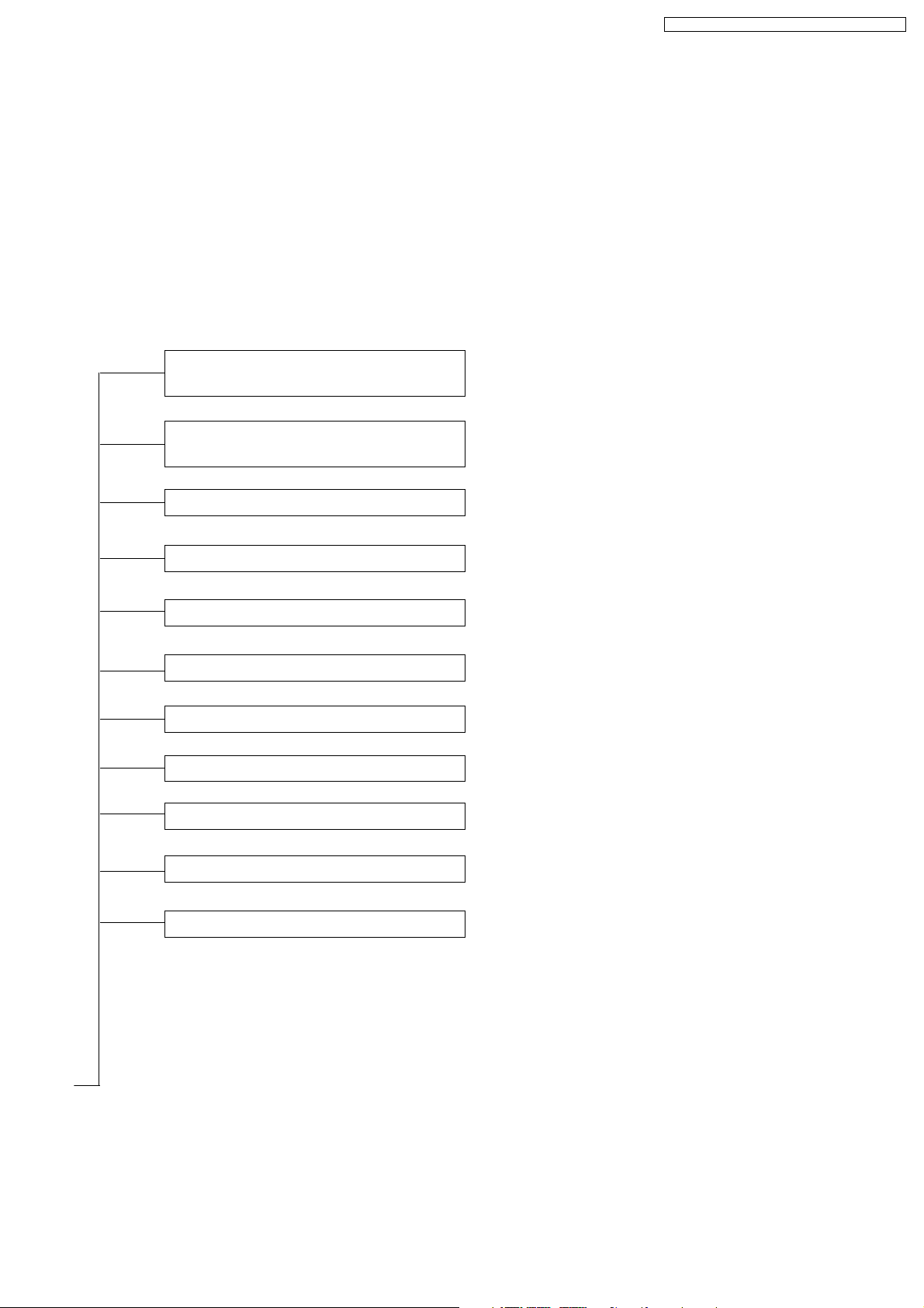
2.3. Outdoor Unit
Time Delay Safety Control
30 seconds Forced Operation
Overload Protection Control
Total Running Current Control
Compressor Overheating
Prevention Control
IPM (Power Transistor)
Overheating Protection Control
Low Operation Frequency
Protection Control
Mininum Operation Frequency
Protection Control
Outdoor Air Temperature
Control
Standby Control
Deice Operation
6
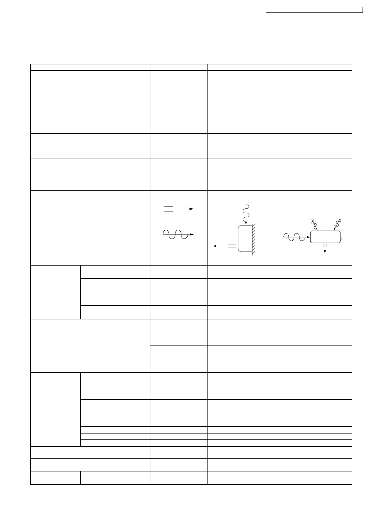
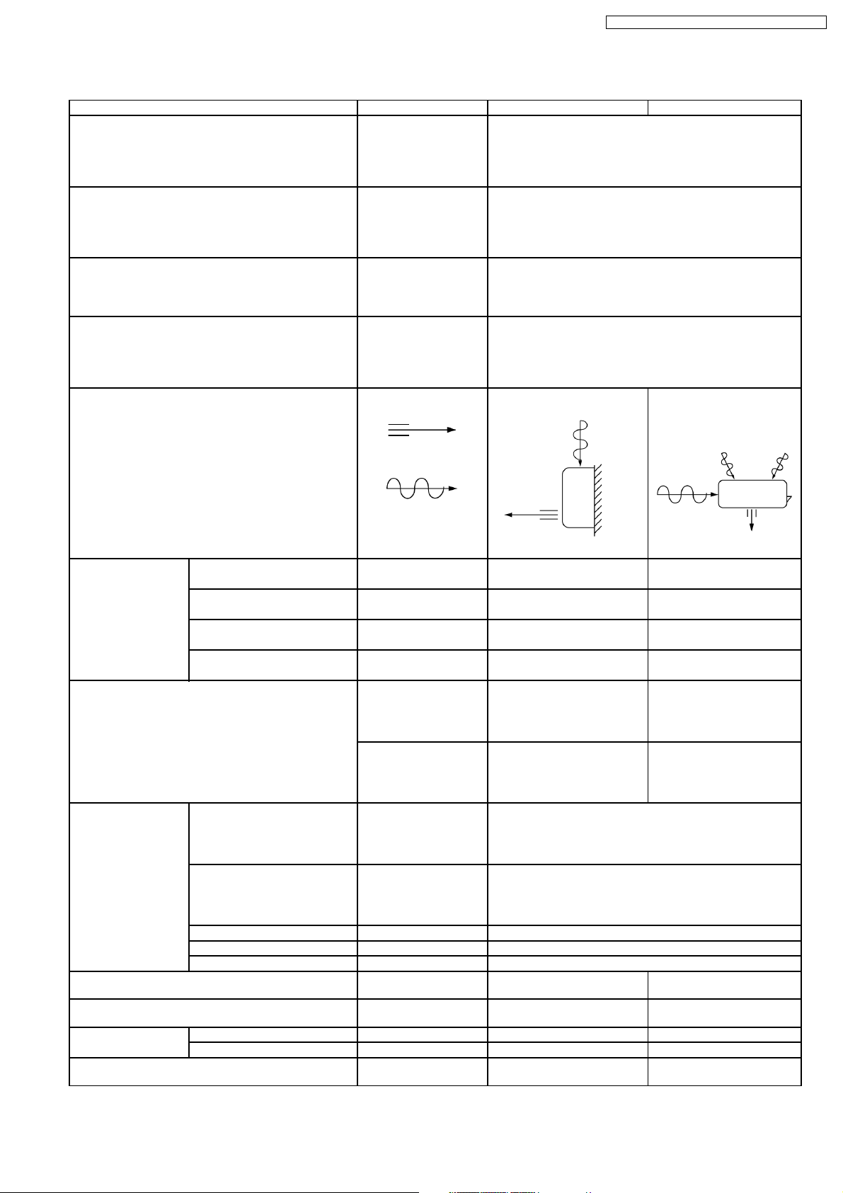
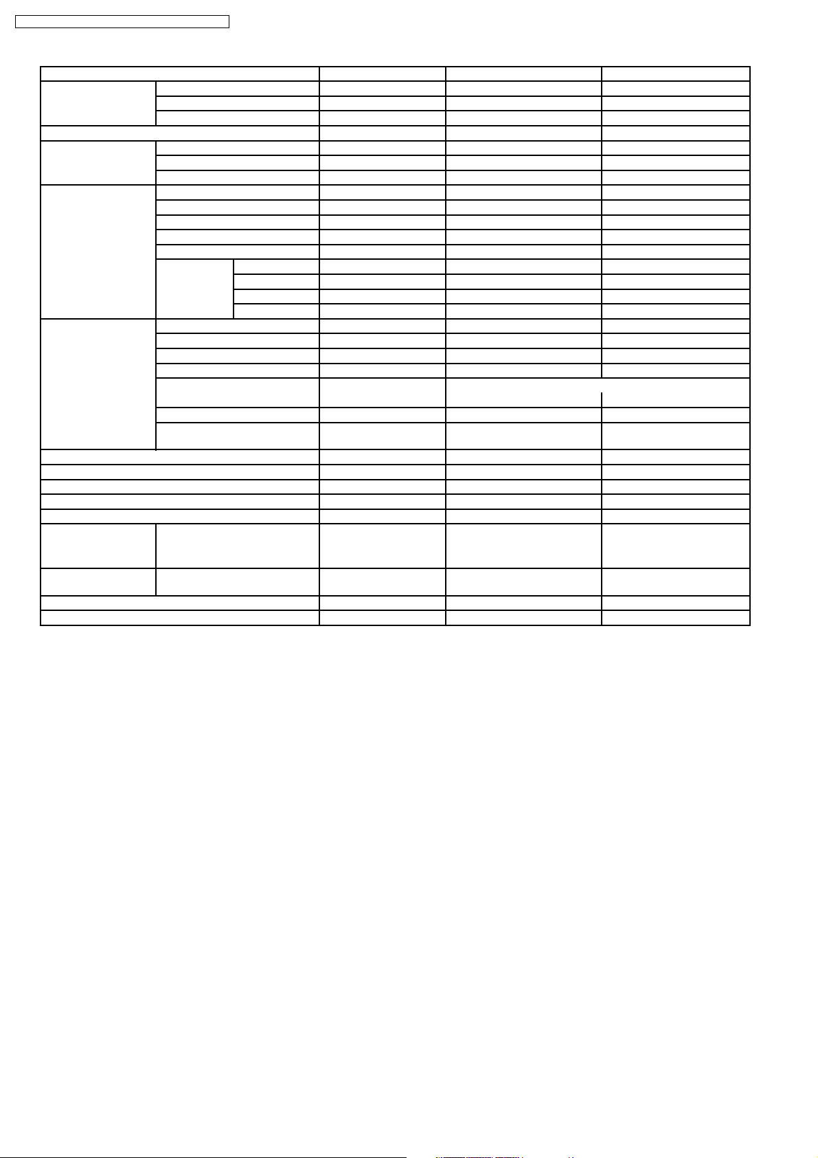
3 Product Specifications
3.1. CS-E9DKDW CU-E9DKD
CS-E9DKDW CU-E9DKD / CS-E12DKD W CU-E12DKD
Unit CS-E9DKDW CU-E9DKD
Cooling Capacity kW
kcal/h
BTU/h
Heating Capacity kW
kcal/h
BTU/h
Moisture Removal l/h
Pint/h
Power Source (Phase, Voltage, Cycle) ø
V
Hz
Airflow Method OUTLET
INTAKE
2.6 (0.80 - 3.00)
2,240 (690 - 2,580)
8,870 (2,050 - 10,200)
3.6 (0.80 - 5.00)
3,100 (690 - 4,300)
12,300 (2,050 - 17,100)
1.6
(3.4)
Single
220 - 230
50
SIDE VIEW TOP VIEW
Air Volume Lo m3/min (cfm) Cooling; 6.2 (220) —
Heating; 6.6 (230)
Me m3/min (cfm) Cooling; 7.9 (280) —
Heating; 8.6 (300)
Hi m3/min (cfm) Cooling; 9.6 (340) Cooling; 29.8 (1,050)
Heating; 10.5 (370)
SHi m3/min (cfm) Cooling; 9.9 (350) —
Heating; 10.8 (380)
dB (A) Cooling; High 39, Low 26 Cooling; 46
Heating; High 40, Low 27 Heating; 47
Noise Level
Power level dB Cooling; High 50 Cooling; High 59
Heating; High 51 Heating; High 60
Electrical Data Input W Cooling; 600 (175 - 780)
Heating; 845 (165 - 1,360)
Running Current A Cooling; 3.0 - 2.9
Heating; 4.2 - 4.0
EER W/W (kcal/hw), BTU/hw Cooling; 4.33 (3.73), 14.8
COP W/W (kcal/hw), BTU/hw Heating; 4.26 (3.67), 14.6
Starting Current A 4.2
Piping Connection Port
(Flare piping)
Pipe Size
(Flare piping)
Drain
Hose
Inner diameter mm 12 —
Length m 0.65 —
inch
inch
inch
inch
G ; Half Union 3/8”
L ; Half Union 1/4”
G (gas side) ; 3/8”
L (liquid side) ; 1/4”
G ; 3-way valve 3/8”
L ; 2-way valve 1/4”
G (gas side) ; 3/8”
L (liquid side) ; 1/4”
7
CS-E9DKDW CU-E9DKD / CS-E12DKD W CU-E12DKD
Unit CS-E9DKDW CU-E9DKD
Power Cord Length
Number of core-wire
Dimensions Height inch (mm) 11 - 1/32 (280) 21 - 1/4 (540)
Width inch (mm) 31 - 15/32 (799) 30 - 23/32 (780)
Depth inch (mm) 7 - 7/32 (183) 11 - 3/8 (289)
Net Weight lb (kg) 20 (9.0) 82 (37)
Compressor Type — Hermetic Rotary
Motor Type — Brushless (6-pole)
Rated Output W — 700
Air Circulation Type Cross-flow Fan Propeller Fan
Material ASG20k1 P.P
Motor Type Transistor (8-poles) Induction (6-poles)
Input W — 61.3
Rate Output W 30 28
Fan Speed Lo (Cool/Heat) rpm 820/880 —
Me (Cool/Heat) rpm 1,050/1,140 —
Hi (Cool/Heat) rpm 1,280/1,400 770
SHi (Cool/Heat) rpm 1,320/1,440 —
Heat Exchanger Description Evaporator Condenser
Tube material Copper Copper
Fin material Aluminium (Pre Coat) Aluminium (Blue Coated)
Fin Type Slit Fin Corrugated Fin
Row / Stage (Plate fin configuration, forced draft)
FPI 21 17
Size (W × H × L) mm 610 × 315 × 25.4 718.4
Refrigerant Control Device — Capillary Tube
Refrigeration Oil (cm3) — RB68A (320)
Refrigerant (R410A) g (oz) — 965 (34.1)
Thermostat Electronic Control —
Protection Device Electronic Control Electronic Control
Length mm — C1, C2 ; 950, C3 ; 411
Capillary Tube Flow Rate l/min — C1, C2 ; 4.1, C3 ; 18.8
Inner Diameter mm — C1, C2 ; 1.1, C3 ; 1.7
Air Filter Material
Style
Fan Motor Capacitor µF, VAC — 2.0 µF, 440 VAC
Compressor Capacitor µF, VAC — 65 µF, 350 VAC
—
—
2/15 2/24
689.8
P.P.
Honeycomb
—
—
× 504 × 36.4
—
•
Specifications are subject to change without notice for further improvement.
8
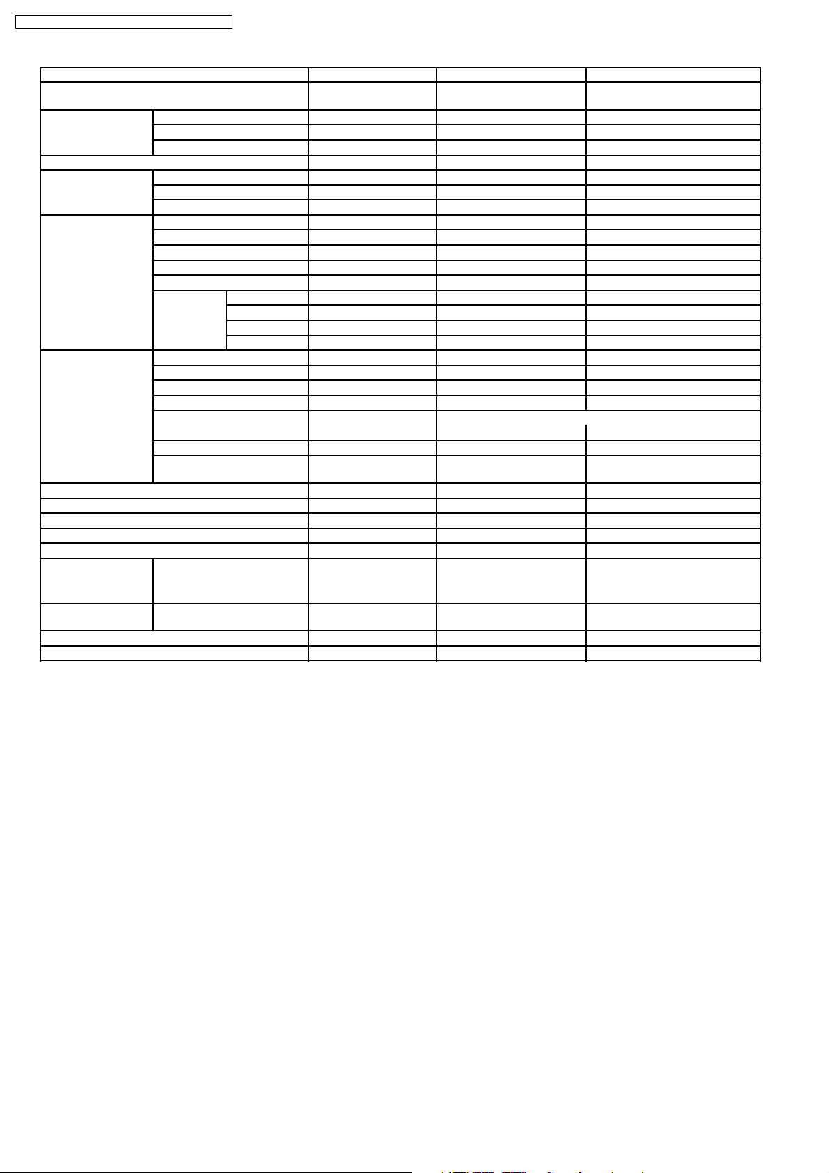
3.2. CS-E12DKDW CU-E12DKD
CS-E9DKDW CU-E9DKD / CS-E12DKD W CU-E12DKD
Unit CS-E12DKDW CU-E12DKD
Cooling Capacity kW
kcal/h
BTU/h
Heating Capacity kW
kcal/h
BTU/h
Moisture Removal l/h
Pint/h
Power Source (Phase, Voltage, Cycle) ø
V
Hz
Airflow Method OUTLET
INTAKE
3.50 (0.80 - 4.00)
3,010 (690 - 3,440)
11,950 (2,730 - 13,600)
4.80 (0.80 - 6.50)
4,130 (690 - 5,590)
16,400 (2,730 - 22,200)
2.0
(4.2)
Single
220 - 230
50
SIDE VIEW TOP VIEW
Air Volume Lo m3/min (cfm) Cooling; 6.9 (240) —
Heating; 8.1 (290)
Me m3/min (cfm) Cooling; 8.8 (310) —
Heating; 9.7 (340)
Hi m3/min (cfm) Cooling; 10.7 (380) Cooling; 31.0 (1,090)
Heating; 11.2 (400)
SHi m3/min (cfm) Cooling; 11.0 (390) —
Heating; 11.6 (410)
dB (A) Cooling; High 42, Low 29 Cooling; 48
Heating; High 42, Low 33 Heating; 50
Noise Level
Power level dB Cooling; High 53 Cooling; High 61
Heating; High 53 Heating; High 63
Electrical Data Input W Cooling; 965 (185 - 1,200)
Heating; 1,260 (175 - 1,890)
Running Current A Cooling; 4.7 - 4.5
Heating; 6.1 - 5.8
EER W/W (kcal/hw), BTU/hw Cooling; 3.63 (3.12), 12.4
COP W/W (kcal/hw), BTU/hw Heating; 3.81 (3.28), 13.0
Starting Current A 6.1
Piping Connection Port
(Flare piping)
Pipe Size
(Flare piping)
Drain
Hose
Power Cord Length
Number of core-wire
Inner diameter mm 12 —
Length m 0.65 —
inch
inch
inch
inch
G ; Half Union 1/2”
L ; Half Union 1/4”
G (gas side) ; 1/2”
L (liquid side) ; 1/4”
—
—
G ; 3-way valve 1/2”
L ; 2-way valve 1/4”
G (gas side) ; 1/2”
L (liquid side) ; 1/4”
—
—
9
CS-E9DKDW CU-E9DKD / CS-E12DKD W CU-E12DKD
Unit CS-E12DKDW CU-E12DKD
Dimensions Height inch (mm) 11 - 1/32 (280) 21 - 1/4 (540)
Width inch (mm) 31 - 15/32 (799) 30 - 23/32 (780)
Depth inch (mm) 7 - 7/32 (183) 11 - 3/8 (289)
Net Weight lb (kg) 20 (9.0) 82 (37)
Compressor Type — Hermetic Rotary
Motor Type — Brushless (6-pole)
Rated Output W — 700
Air Circulation Type Cross-flow Fan Propeller Fan
Material ASG20k1 P.P
Motor Type Transistor (8-poles) Induction (6-poles)
Input W — 65.9
Rate Output W 30 29
Fan Speed Lo (Cool/Heat) rpm 910/1,080 —
Me (Cool/Heat) rpm 1,165/1,290 —
Hi (Cool/Heat) rpm 1,420/1,500 830
SHi (Cool/Heat) rpm 1,460/1,540 —
Heat Exchanger Description Evaporator Condenser
Tube material Copper Copper
Fin material Aluminium (Pre Coat) Aluminium (Blue Coated)
Fin Type Slit Fin Corrugated Fin
Row / Stage (Plate fin configuration, forced draft)
2/15 2/24
FPI 21 17
Size (W × H × L) mm 610 × 315 × 25.4 718.4
Refrigerant Control Device — Capillary Tube
Refrigeration Oil (cm3) — RB68A (320)
Refrigerant (R410A) g (oz) — 980 (34.6)
Thermostat Electronic Control —
Protection Device Electronic Control Electronic Control
Length mm — C1, C2 ; 1,120, C3 ; 370
Capillary Tube Flow Rate l/min — C1, C2 ; 4.9, C3 ; 19.6
Inner Diameter mm — C1, C2 ; 1.2, C3 ; 1.7
Air Filter Material
Style
Fan Motor Capacitor µF, VAC — 2.0 µF, 440 VAC
Compressor Capacitor µF, VAC — 65 µF, 350 VAC
P.P.
Honeycomb
× 504 × 36.4
689.8
—
•
Specifications are subject to change without notice for further improvement.
10
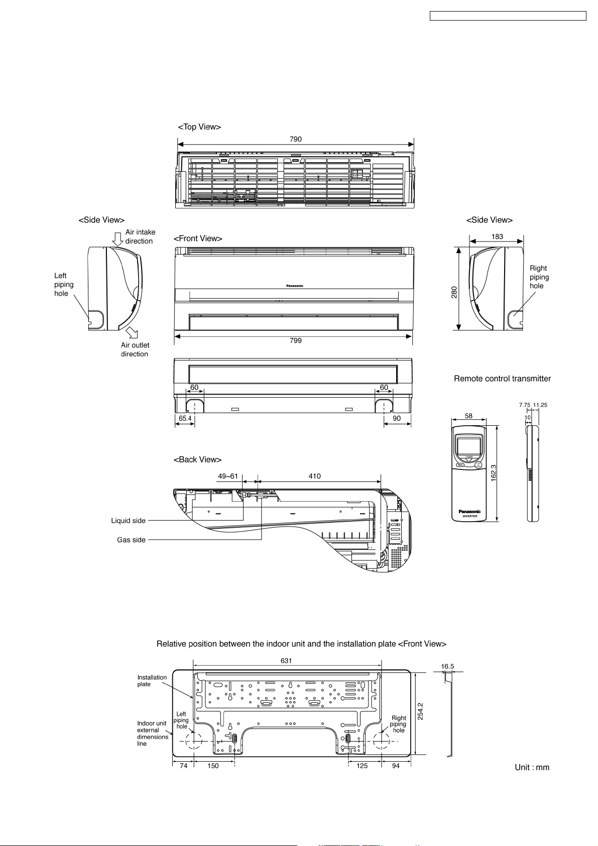
4 Dimensions
4.1. Indoor Unit & Remote Control
4.1.1. CS-E9DKDW CS-E12DKDW
CS-E9DKDW CU-E9DKD / CS-E12DKD W CU-E12DKD
11
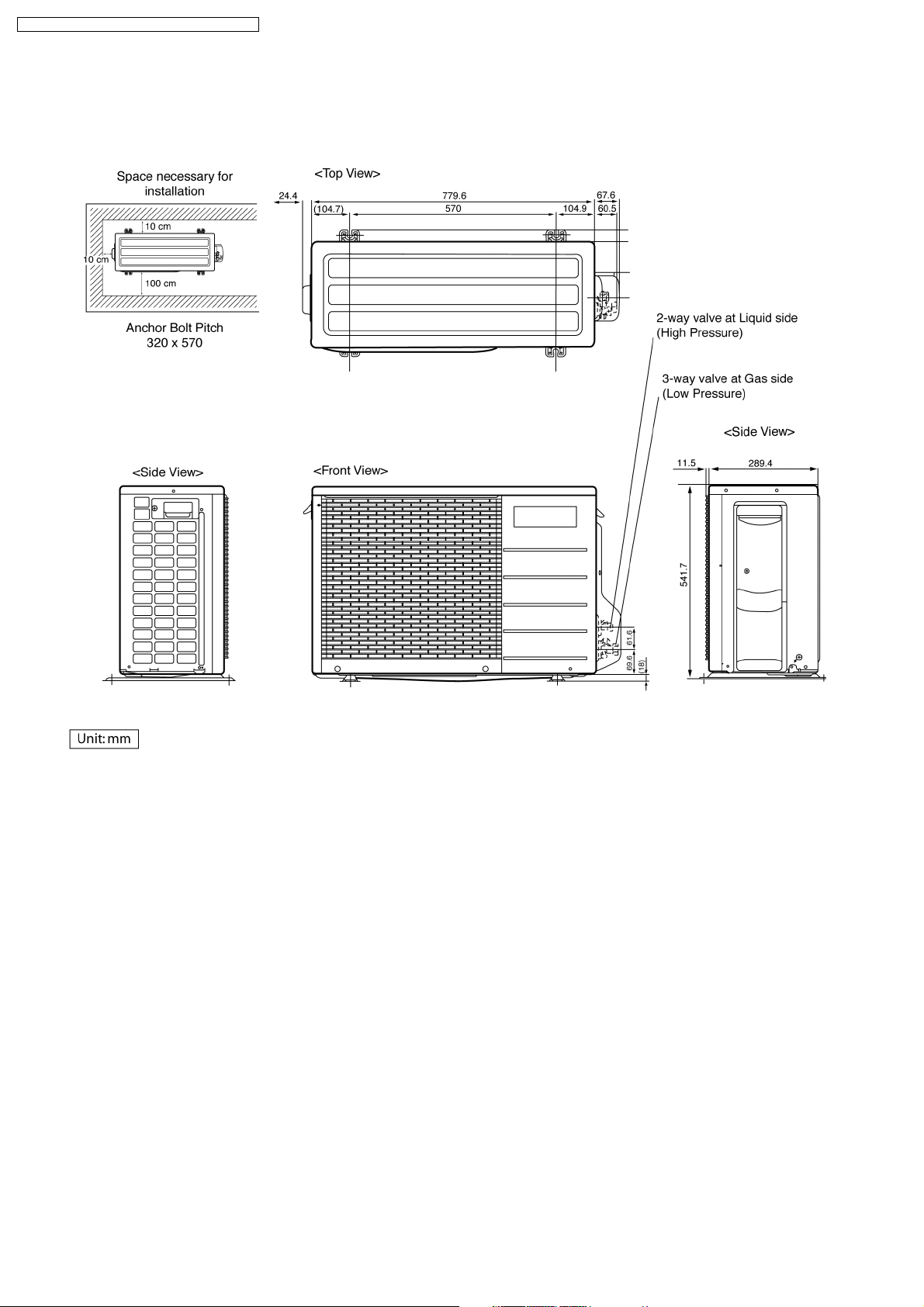
CS-E9DKDW CU-E9DKD / CS-E12DKD W CU-E12DKD
4.2. Outdoor Unit
4.2.1. CU-E9DKD CU-E12DKD
12
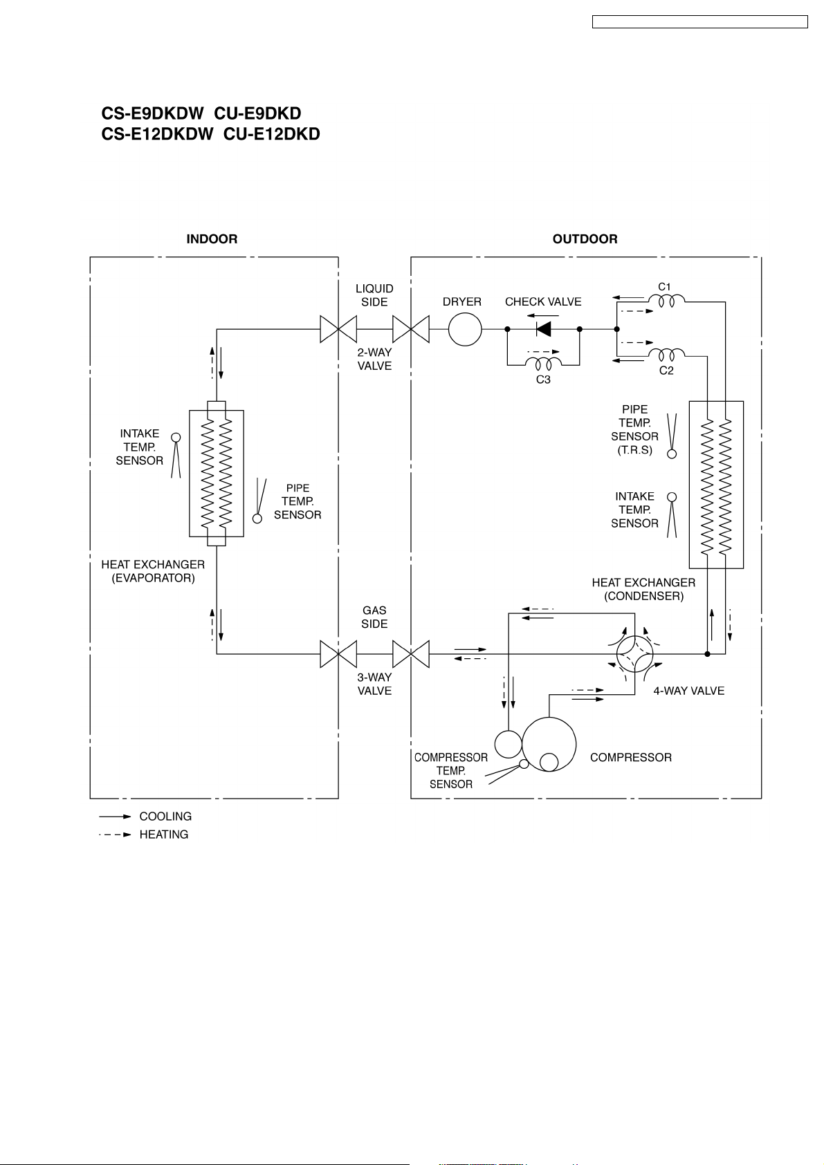
5 Refrigeration Cycle Diagram
CS-E9DKDW CU-E9DKD / CS-E12DKD W CU-E12DKD
13
CS-E9DKDW CU-E9DKD / CS-E12DKD W CU-E12DKD
6 Block Diagram
14
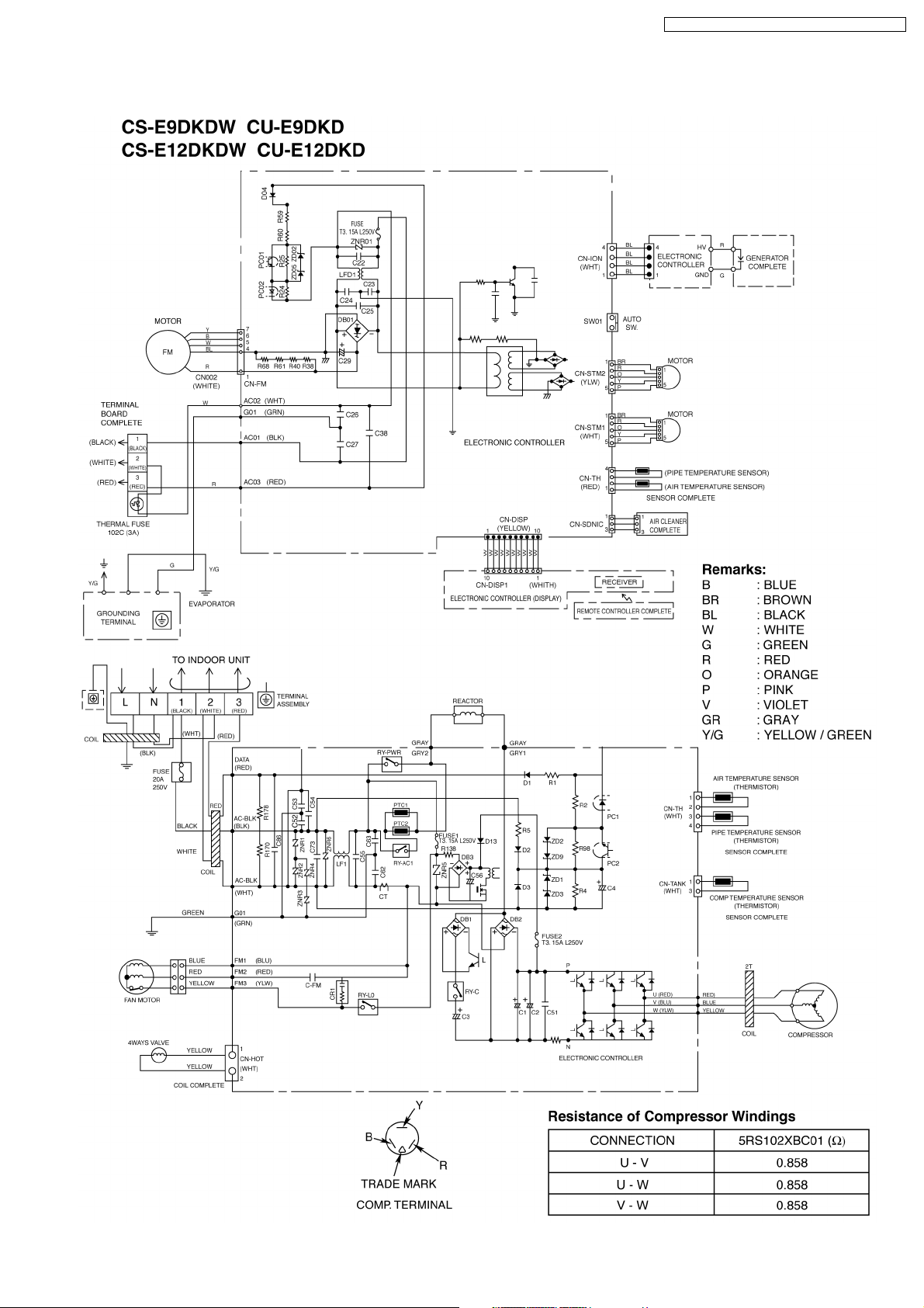
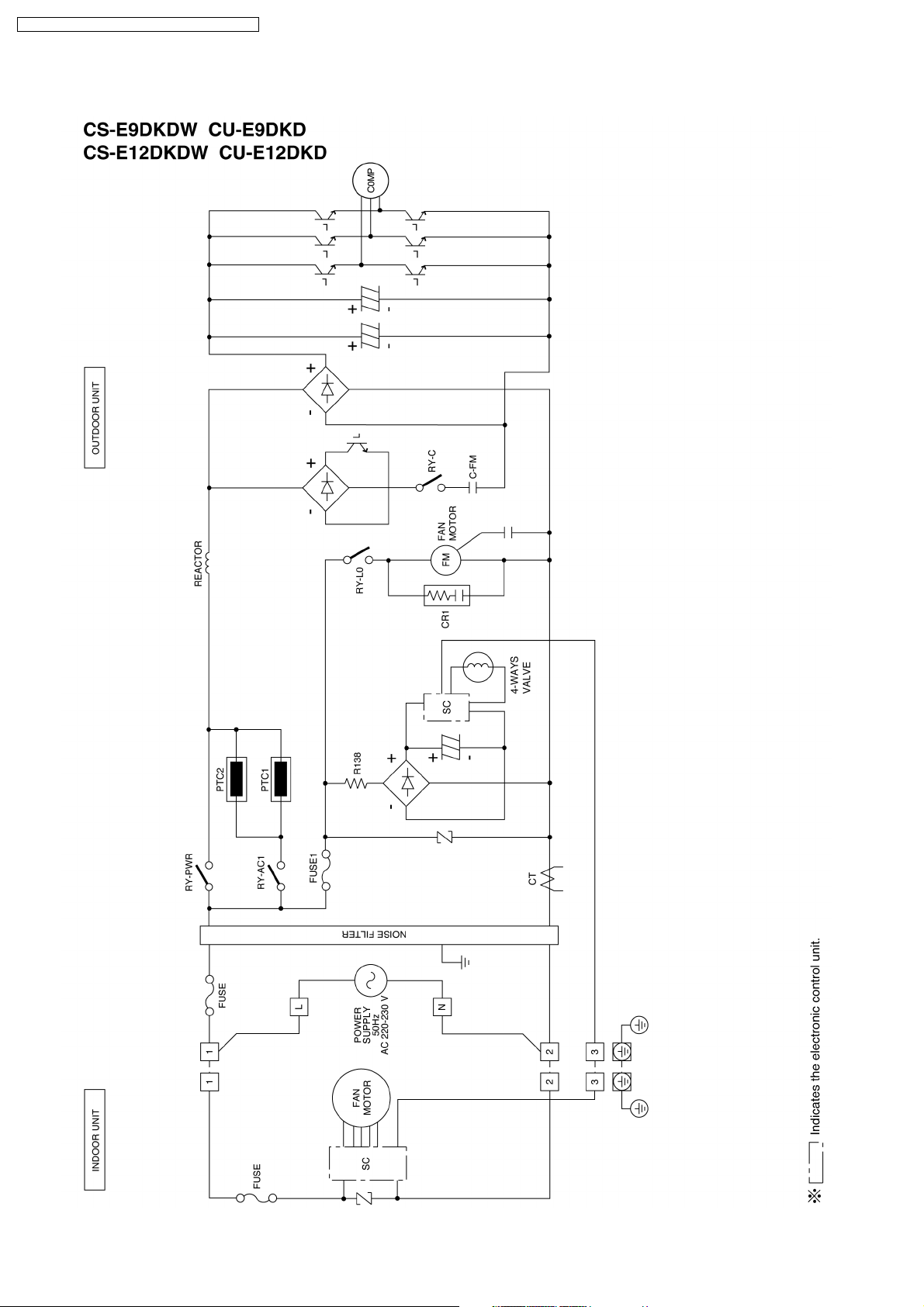
7 Wiring Diagram
CS-E9DKDW CU-E9DKD / CS-E12DKD W CU-E12DKD
15
CS-E9DKDW CU-E9DKD / CS-E12DKD W CU-E12DKD
8 Operation Details
8.1. Basic Function
Inverter control, which equipped with a microcomputer in determining the most suitable operating mode as time passes,
automatically adjusts output power for maximum comfort always. In order to achieve the suitable operating mode, the
microcomputer maintains the set temperature by measuring the temperature of the environment and performing temperature
shifting. The compressor at outdoor unit is operating following the frequency instructed by the microcomputer at indoor unit that
judging the condition according to internal setting temperature and intake air temperature.
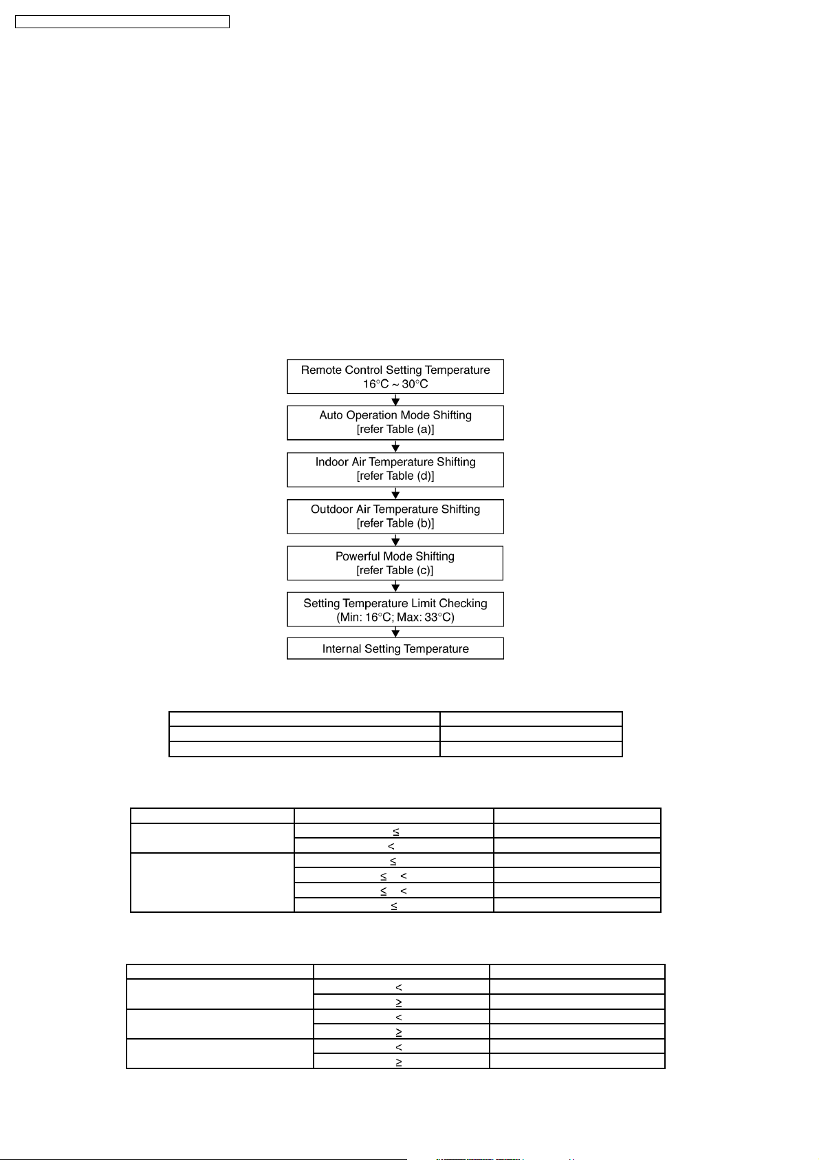
8.1.1. Internal Setting Temperature
Once the operation starts, remote control setting temperature will be taken as base value for temperature shifting processes.
These shifting processes are depending on the air conditioner settings and the operation environment. The final shifted value
will be used as internal setting temperature and it is updated continuously whenever the electrical power is supplied to the unit.
Table (a): Auto Operation Mode Setting
Mode Shift: Temperature Shift (°C)
Cooling/Soft Dry→Heating -2.0
Heating→Cooling/Soft Dry +2.0
Table (b): Outdoor Air Temperature Shifting
Mode: Outdoor Temperature, X (°C): Temperature Shift (°C)
Cooling/Soft Dry 30 X +0.5
Heating 9 X -1.0
Table (c): Powerful Mode Shifting
Mode: Period, X (min): Temperature Shift (°C)
Cooling X 20 -2.0
Soft Dry X 20 -1.0
Heating X 20 +3.5
X 30 +1.0
5 X 9 -0.5
1 X 5 0.0
X 1 +1.0
X 20 0.0
X 20 0.0
X 20 +3.5
16
CS-E9DKDW CU-E9DKD / CS-E12DKD W CU-E12DKD
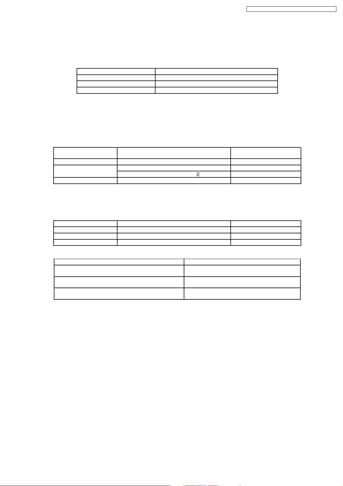
Table (d): Indoor Air Temperature Shifting
1. Target room temperature shift value (dGetaDst)
To offset the absolute gap between detection temperature with actual room temperature.
•
The heat exchanger unit’s temperature is different based on operation mode, it become the action operation mode
•
value.
Actual operation mode Target room temperature offset value (dGetaDst)
Cooling (1)
Heating (2)
Dry (0)
2. Room temperature shift value (dGeta)
When compressor ON/OFF, correction of detected room temperature by shift value during defrost etc.
•
i) Initial value when operation starts, or changin g the actual operation mode.
Set the offset value at each operation mode. However, in order to improve the heating start up efficiency, the offset value
will be changed based on the gap between setting temperature and room temperature.
Actual operation mode Gap between setting temperature and room
temperature
Cool — (0)
Heat (Operation start set temp. - room temp) <4°C (4)
(Operation start set temp.) 4°C (4)
Dry — (0)
Room temperature offset value
(dGeta)
ii) Updating during operation
During operation, it will compare with the target room temperature offset value at specific period, then the room temperature
will be updated.
Actual operation mode Room temperature zone Updating period (sec.)
Cool — (180)
Heat A, B, C, D zone (15)
Dry — (180)
Update the room temperature offset value (dGeta)
Temperature condition Room temp. offset value after modified (dGeta)
Target room temp. offset value > Room temp. offset value
(dGetaDst > dGeta)
Target room temp. offset value < Room temp. offset value
(dGetaDst < dGeta)
Target room temp. offset value = Room temp. offset value
(dGetaDst = dGeta)
dGeta + (0.5)
dGeta - (0.5)
Do not change
However, if the following condition is occurred, temperature cannot detect correctly and therefore no updatin g will be done.
Heating zone E and above (Temperature gap is big and great capacity increased)
•
During deice
•
After deice complete *within 600 sec.
•
Comp stop
•
Comp starting *within 600 sec.
17
CS-E9DKDW CU-E9DKD / CS-E12DKD W CU-E12DKD
8.1.2. Compressor Operation Frequency
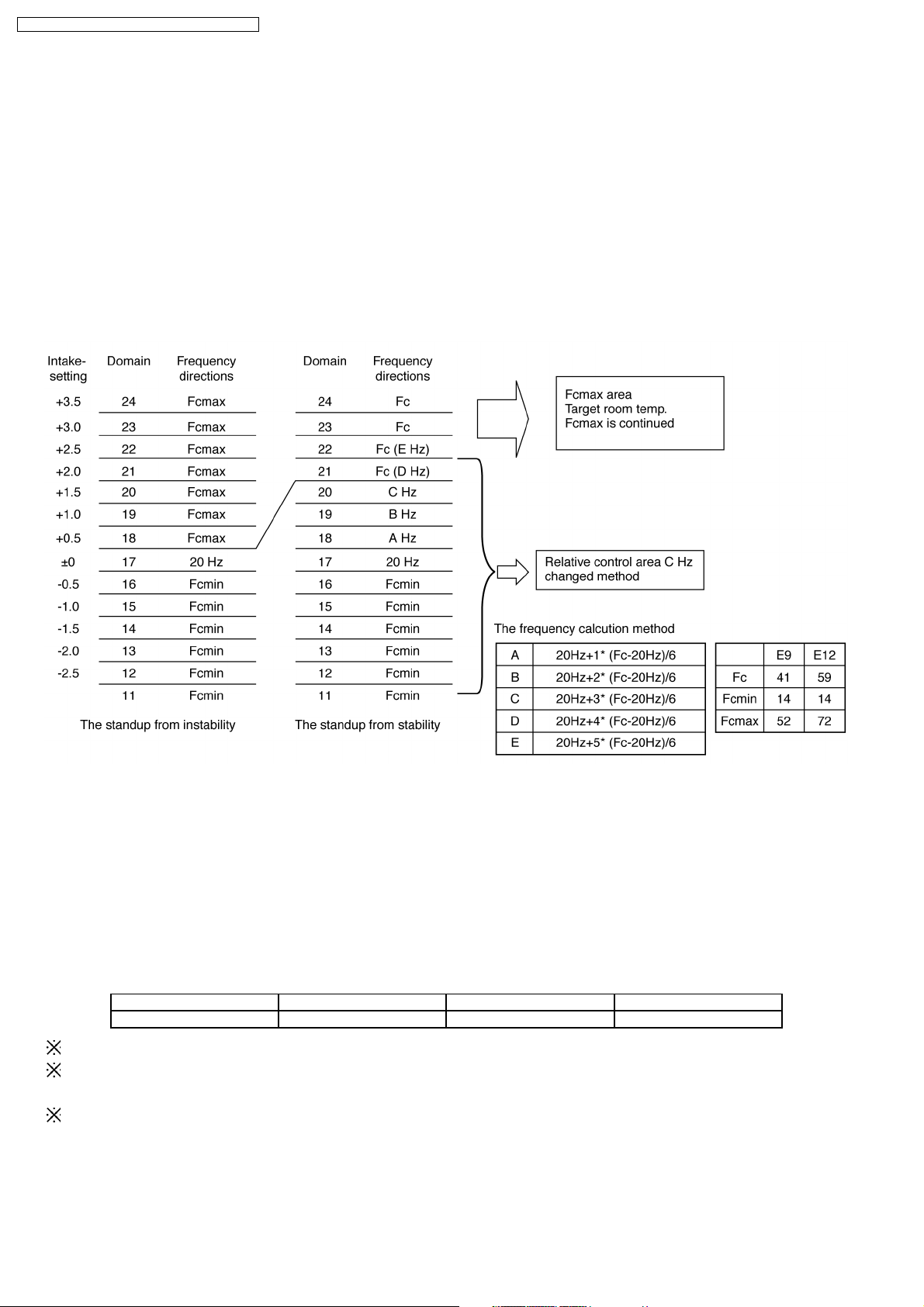
8.1.2.1. The frequency determination method (Cooling operation control)
8.1.2.1.1. Basic specification
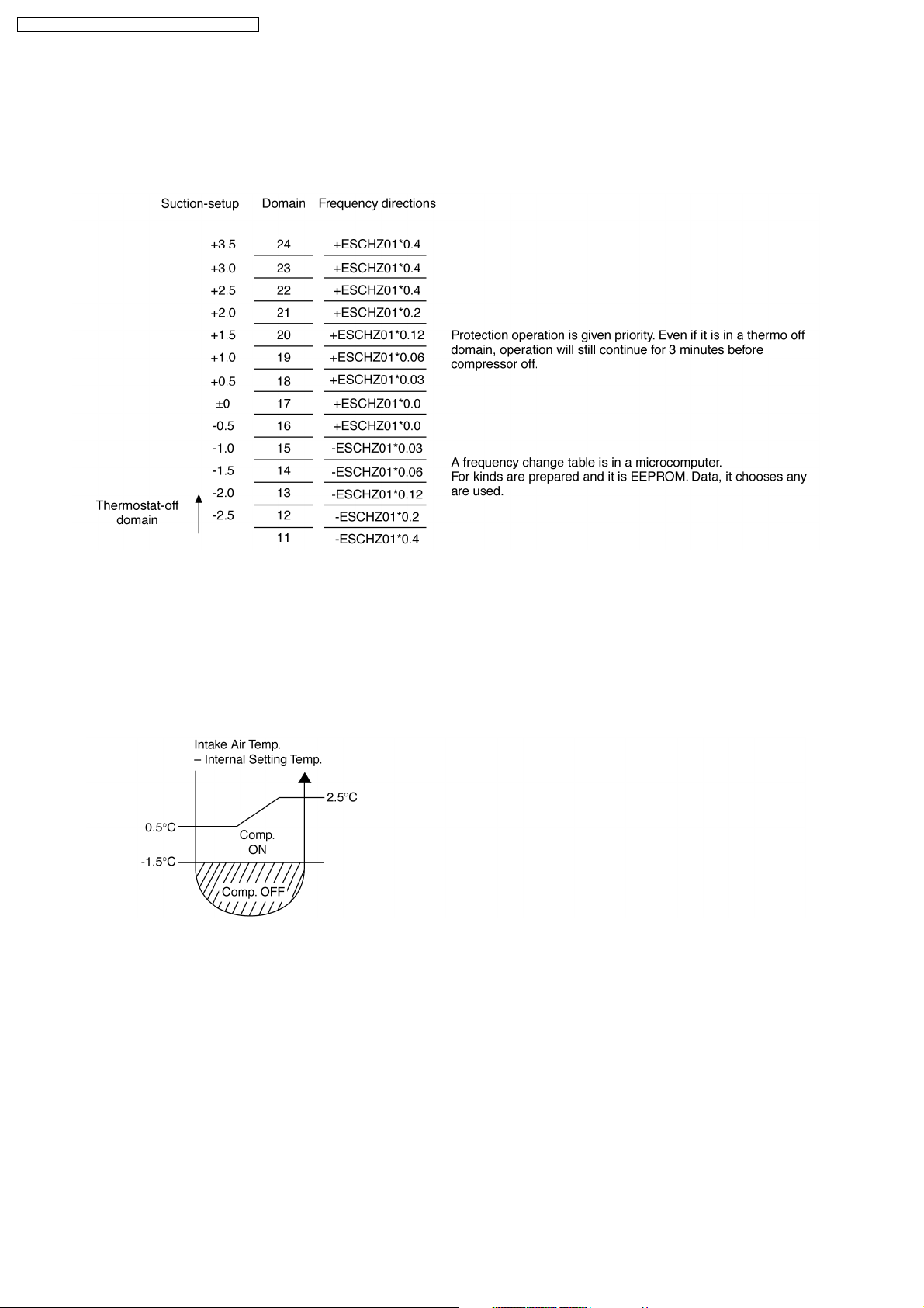
The domain directions data (intake-setting) transmitted from the interior of a room determines a changed part of frequency.
Then, a directed changed part changes frequency to the present frequency.
8.1.2.1.2. Initial frequency determination
After a starting control end, initial frequency (absolute value) is determined.
However, a FcMAX domain judges instantly.
8.1.2.1.3. Change frequency determination
When (Suction-setup) is +0.5deg, directions of Fcmax came by the mentioned initial frequency.
Fcmax continued until it reaches. (If other directions came by protection control, priority is given)
When room temperature is reached, it shifts to relative control after moving to change frequency.
The following operation determines change frequency.
The Hzkirikae = present condition frequency * Inclines and it is calculation.
Inclination = lapsed time to remote control attaintment (Minute)
Inclination 0-60 60 - 90 90
Inclination coefficient 80% 90% 100%
1. The present frequency is real operation frequency.
2. When change directions come out with remote control after starting, continue calculation as it is.
The time to room temperature attainment is calculated.
3. When remote control directions were changed before room temperature attainment and below room temperature attainment
temperature becomes
With initial frequency, it is considered as change frequency.
18
CS-E9DKDW CU-E9DKD / CS-E12DKD W CU-E12DKD
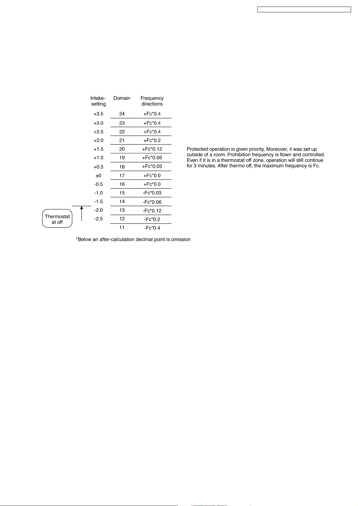
8.1.2.1.4. The frequency changed method
1. After shifting to relative control, (intake-setting) is every 60 seconds, A tap is adjusted according to the domain and frequency
changes relatively to present condition.
2. Intake-setting to other domains by load sudden change (remote control setting, open air introduction, etc.). When it moves, it
has the following renewal of data, an addition and subtraction tap is switched.
3. When the load change was further carried out and suction-setup separates the domain of relative control, it goes to the clause
of initial frequency and operation frequency is determined.
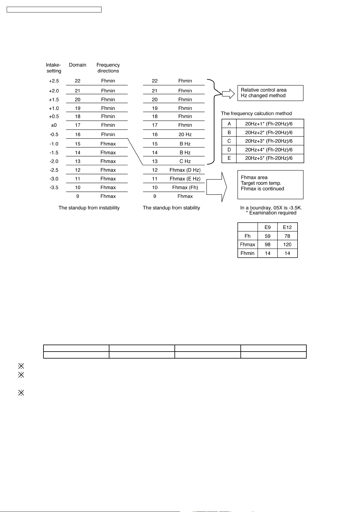
8.1.2.2. The frequency determination method (Heating operation control)
8.1.2.2.1. Basic specification
Intake temperature domain is sent to outdoor. Renewal of data every 60 seconds in outdoor.
Domain directions data (intake-setting) transmitted from indoor determine a changed part of frequency.
Then, a directed changed part changes frequency to the present frequency.
Change of frequency may be 1 tap = 1Hz.
19
CS-E9DKDW CU-E9DKD / CS-E12DKD W CU-E12DKD
8.1.2.2.2. Initial frequency determination
After a starting control end, initial frequency (absolute value) is determined and is immediately shift.
However, the domain of Fhmax is judged instantly.
8.1.2.2.3. Change frequency determination
When directions of Fhmax determined from mentioned initial frequency, (intake-setting) relativity control. Fhmax continued until (If
other directions came by protection control, priority is given there) room temperature is reached, it shifts to relative control after
moving to change frequency.
The following operation determines change frequency.
The Hzkirikae = present condition frequency *Inclines (calculation)
Inclination = Lapsed time to remote control attainment (min)
Inclination 0-30 30 - 60 60
Inclination coefficient 70% 90% 100%
1. The present frequency is real operation frequency.
2. When directions change come out by remote control after starting, calculation continued.
The time to room temperature attainment is calculated.
3. When remote control directions were changed before room temperature achieved and below room temperature attainment
temperature becomes
With initial frequency, it is considered as change frequency.
20
CS-E9DKDW CU-E9DKD / CS-E12DKD W CU-E12DKD
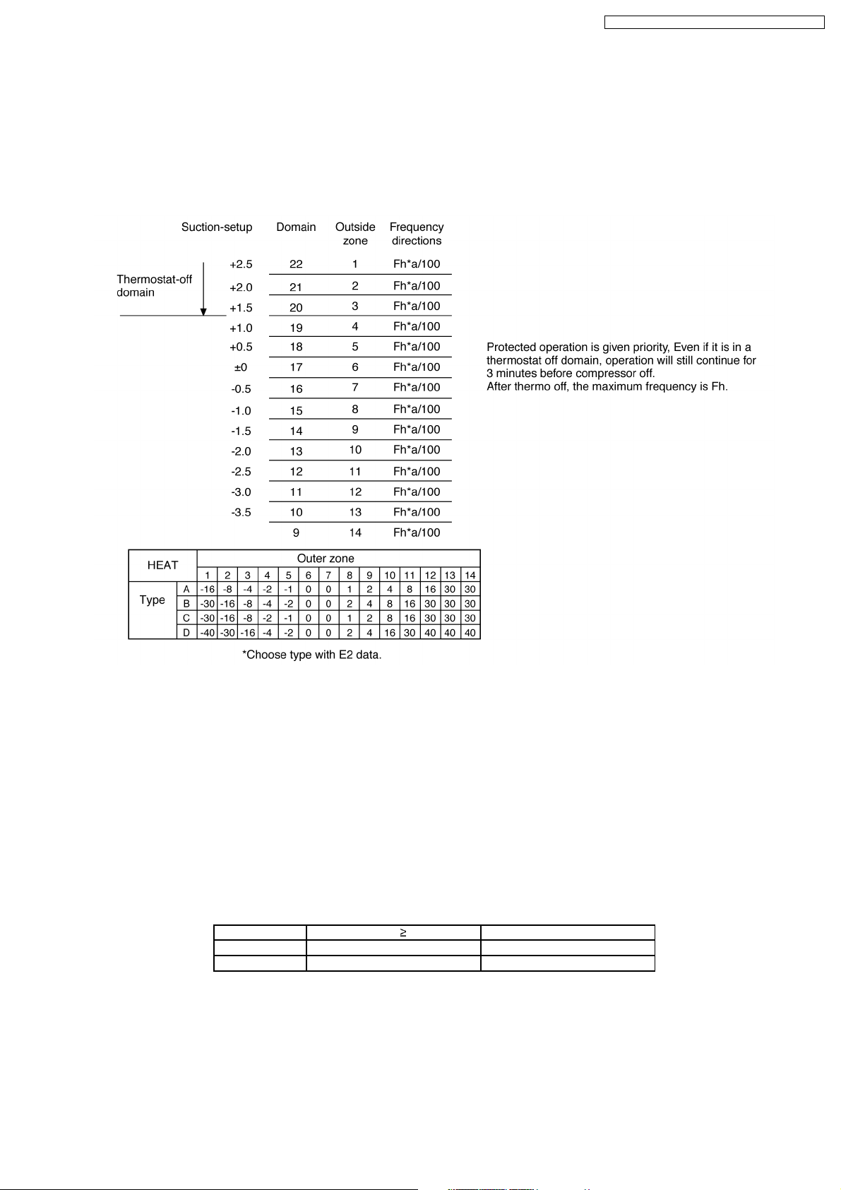
8.1.2.2.4. The frequency changed method
1. When intake-setting remains for 30 seconds in a domain after shifting to relative control, a tap is adjusted according to the
domain and frequency changes relatively to the present condition.
2. A suction-setup to other domains by load sudden change (remote control setting change, open air introduction, etc.).
When it moves, addition or subtraction tap is changed at the time of the following renewal of data.
3. When the load change was furthermore carried out and a suction-setup separates from the domain of relative control, it goes
to the clause of initial frequency and operation frequency is determined.
8.1.2.3. The frequency determination method (Soft Dry operation control)
8.1.2.3.1. Basic specification
The domain directions data (intake-setting) transmitted from indoor determines a changed part of frequency.
Then, a directed changed part changes frequency to the present frequency.
Change of frequency may be 1 tap = 1Hz.
It applies to cooling correspondingly.
8.1.2.3.2. Initial frequency determination
It shifts to initial frequency after a starting frequency end.
Frequency ESCHZ02 ESCHZ01
ID intake 22°C ID intake < 22°C
38 (E12), 31 (E9) 34 (E12), 28 (E9)
21
CS-E9DKDW CU-E9DKD / CS-E12DKD W CU-E12DKD
8.1.2.3.3. The frequency change method
1. When (suction-setup) remains in a domain for 30 seconds, after shifting to relative control, a tap is adjusted according to the
domain and frequency changes relatively to the present condition.
2. A suction-setup is to other domains by load sudden change (remote control setting, open air introduction, etc.). When it moves,
an addition-and-subtraction tap is changed from the time of the following renewal of data.
8.1.3. Cooling Operation
8.1.3.1. Thermostat control
Compressor is OFF when Intake Air Temperature - Internal Setting Temperature < -1.5°C.
•
Compressor is ON after waiting for 3 minutes, if the Intake Air Temperature - Internal Setting Temperature > Compressor OFF
•
point.
22
CS-E9DKDW CU-E9DKD / CS-E12DKD W CU-E12DKD
8.1.4. Soft Dry Operation
8.1.4.1. Thermostat control
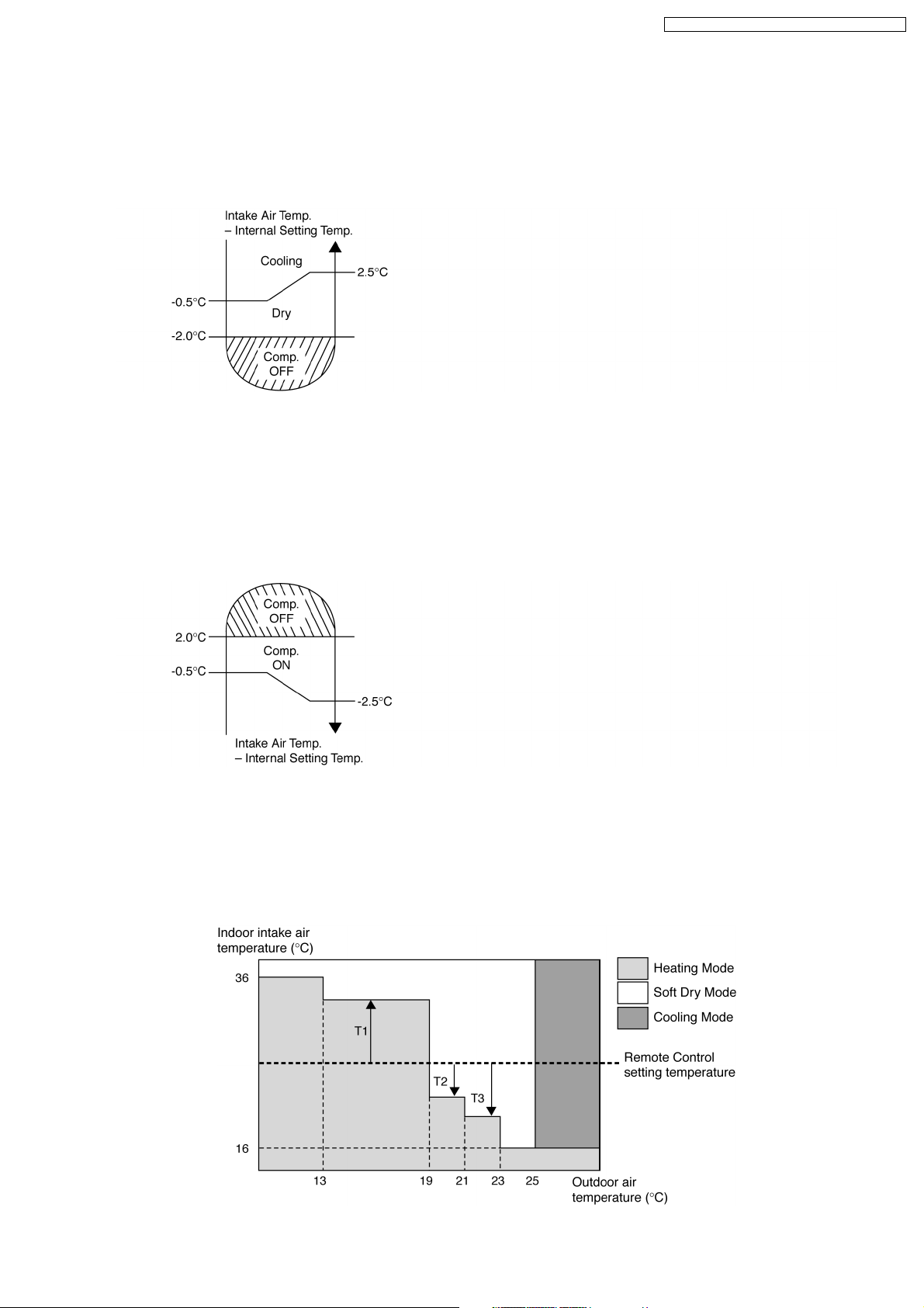
Compressor is OFF when Intake Air Temperature - Internal Setting Temperature < -2.0°C.
•
Compressor is ON after waiting for 3 minutes, if the Intake Air Temperature - Internal Setting Temperature > Compressor OFF
•
point.
8.1.5. Heating Operation
8.1.5.1. Thermostat control
Compressor is OFF when Intake Air Temperature - Internal Setting Temperature > +2.0°C.
•
Compressor is ON after waiting for 3 minutes, if the Intake Air Temperature - Internal Setting Temperature < Compressor OFF
•
point.
8.1.6. Automatic Operation
This mode can be set using remote control and the operation is decided by remote control setting temperature, indoor intake air
temperature and outdoor air temperature.
During operation mode judgment, indoor fan motor (with speed of Lo-) and outdoor fan motor are running for 30 seconds to detect
the indoor intake and outdoor air temperature. The operation mode is decided based on below chart.
23
CS-E9DKDW CU-E9DKD / CS-E12DKD W CU-E12DKD
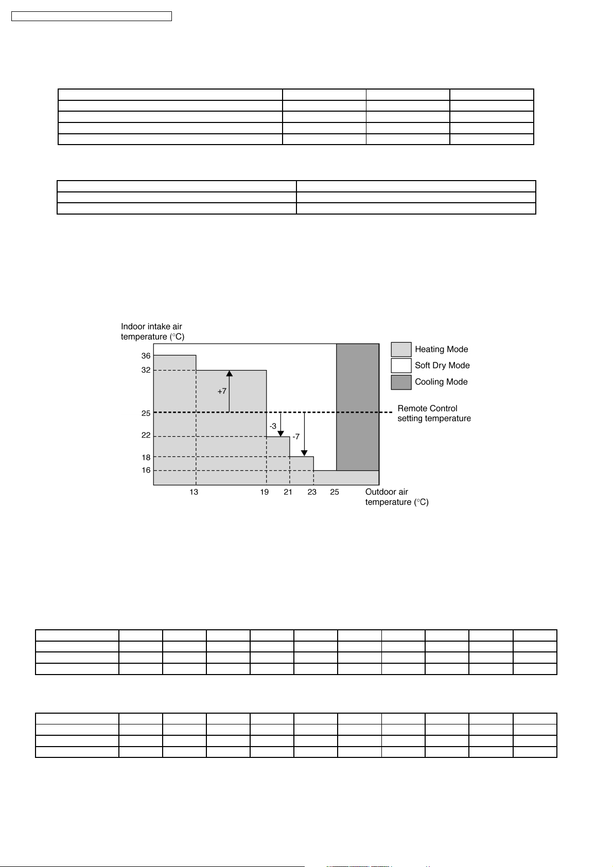
Values of T1, T2, and T3 depend on remote control setting temperature, as shown in below table. After the adjustment of T1, T2
and T3 values, the operation mode for that particular environment and remote control setting is judged and performed, based on
the above operation mode chart, every 30 minutes.
Remote Control Setting Temperature (°C) T1 T2 T3
16 ~ 18 +10 -3 -5
19 ~ 22 +8 -3 -7
23 ~ 26 +7 -3 -7
27 ~ 30 +6 -3 -8
There is a temperature shifting on T1, T2, and T3 if the operation mode judged is changed from Cooling/Soft Dry to Heating or vice
verse.
Operation Mode change from Temperature shifts (°C)
Cooling/Soft Dry→Heating -2
Heating→Cooling/Soft Dry +2
Example of operation mode chart adjustment:
From the above table, if remote control setting temperature = 25,
T1 = 25 + 7 = 32; T2 = 25 - 3 = 22; T3 = 25 - 7 = 18
The operation mode chart for this example is as shown in below figure and the operation mode to be performed will depend on
indoor intake air temperature and outdoor air temperature at the time when the judgment is made.
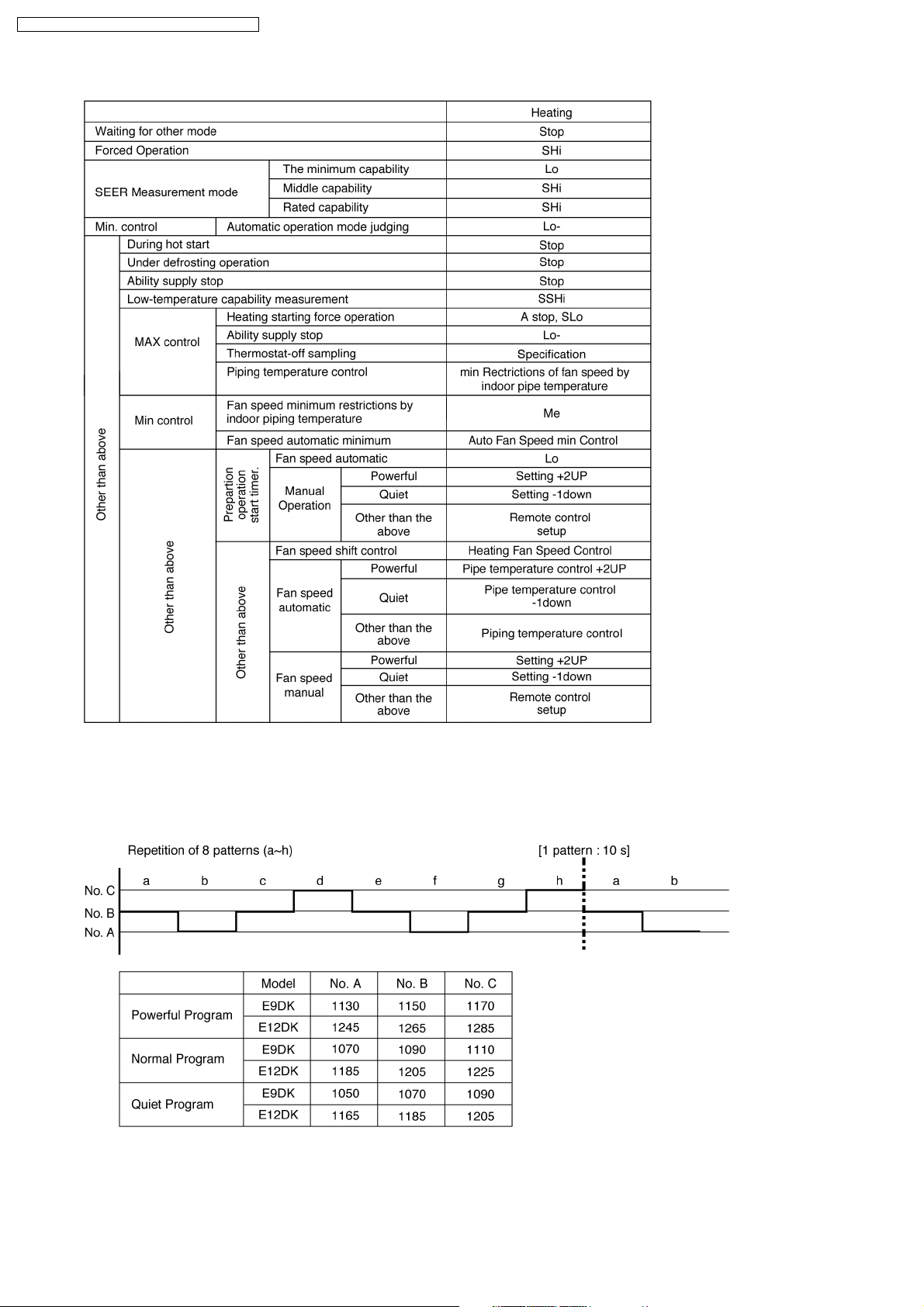
8.1.7. Indoor Fan Motor Operation
A. Basic Rotation Speed (rpm)
Required rotation speed for fan is set to respond to the remote control setting (10 rpm unit)
•
[Cooling, Dry, Fan]
Remote Control — — O O O O O — — —
Tab (rpm) PSHI SHI Hi Me+ Me Me- Lo Lo- SLo SSLo
E9DK 1320 1320 1280 1165 1050 935 820 760 720 710
E12DK 1460 1460 1420 1293 1165 1038 910 840 720 710
[Heating]
Remote Control — — O O O O O — — —
Tab (rpm) PSHi SSHi SHi Me+ Me Me- Lo Lo- SLo SSLo
E9DK 1440 1440 1400 1270 1140 1010 880 820 720 710
E12DK 1540 1540 1500 1395 1290 1185 1080 1010 720 710
24
B. Indoor Fan Control
i. Indoor fan control operation outline
1. Cooling / Dry
CS-E9DKDW CU-E9DKD / CS-E12DKD W CU-E12DKD
25
CS-E9DKDW CU-E9DKD / CS-E12DKD W CU-E12DKD
2. Heating
ii. Auto Fan Speed
1. Cooling
26
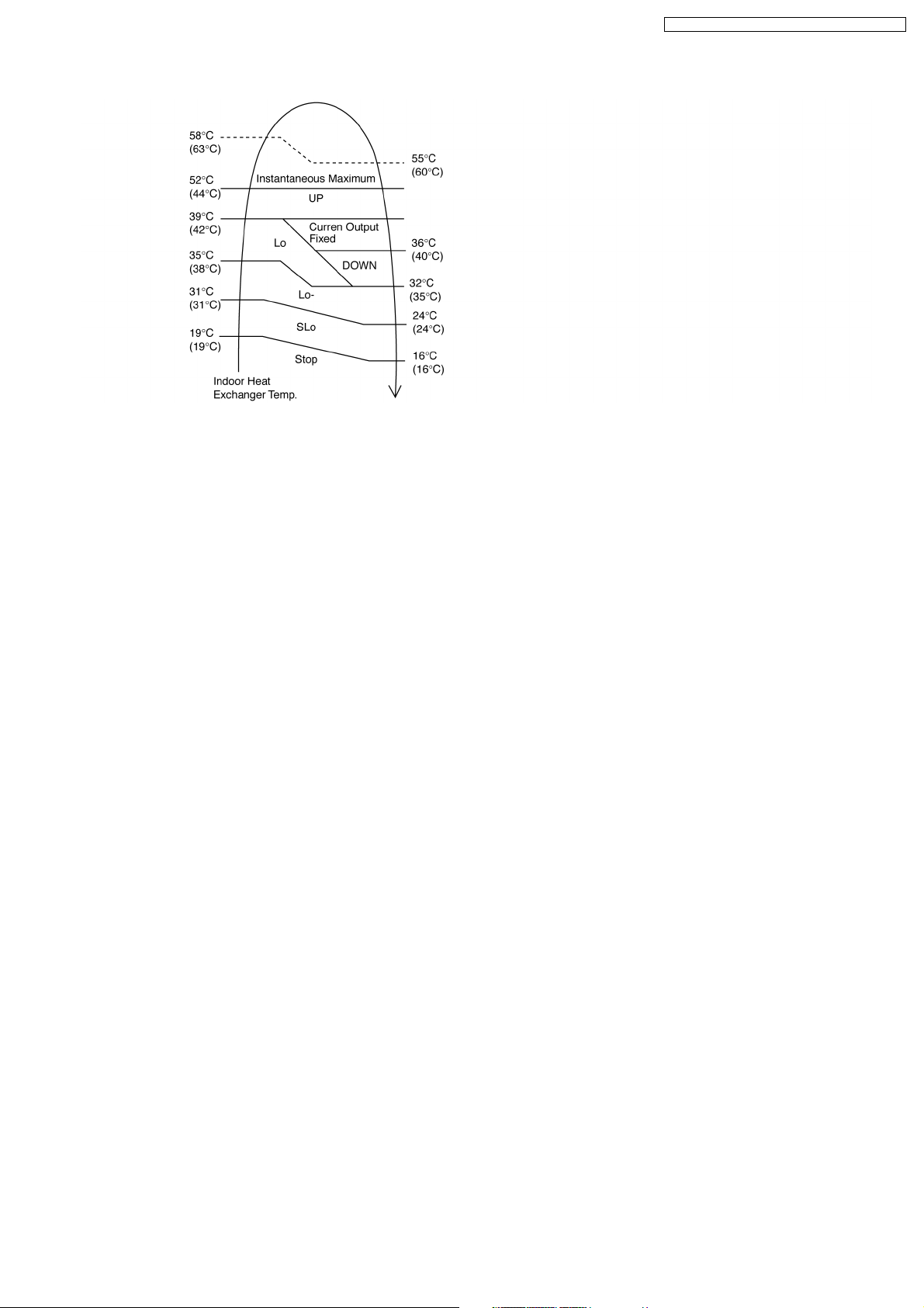
2. Heating
Note:
a. UP:
If move from Lo, the fan speed will be shifted to Maximum 1520 rpm.
•
If move from Maximum, the fan speed no change.
•
In up zone, 10 rpm is added for every 10s until Maximum 1520 rpm.
•
b. DOWN:
The fan speed will be decreased one step every 10 sec. until Minimum 1270 rpm.
•
c. Current Output Fixed:
Maintain at present fan speed.
•
d. Instantaneous Maximum:
Fan speed will be increased to maximum auto fan speed.
•
e. Temperature in ( ) is for Powerful Mode operation.
CS-E9DKDW CU-E9DKD / CS-E12DKD W CU-E12DKD
C. Fan Motor Control
1. Motor specification
High voltage PWM Motor
2. Feedback Control
a. Number-of-rotations feedback
Immediately after the fan started, rpm is checked and duty is added, and feedback control is performed. For high voltage
PWM motor, it is done once every 0.5 second.
b. Offset duty T max/min limit
High voltage PWM motor has maximum offset duty.
(Refer Indoor fan motor control basic rotation speed)
3. Abnormal Detection Control
Conditions:
a. Out of rhythm signal input
b. If feedback number of rotations exceeded #2550 r/min or when less than #50 r/min.
Control: Fans stop
Return: Restart after 5 seconds
* It will not detect the out of rhythm condition within 5s for phase control motor (PWM motor is when duty=0) after start.
A fan stops when condition (1) and (2) happen within 25.0 seconds after fan starting, and if this happens for continuously
7 times, it will not retry.
FM lock processing
→
4. Restart Prohibition Control
Restart is prohibited within 5s for phase control motor (PWM motor is when duty=0) after fan stop (except re-ON the power
supply).
27
CS-E9DKDW CU-E9DKD / CS-E12DKD W CU-E12DKD
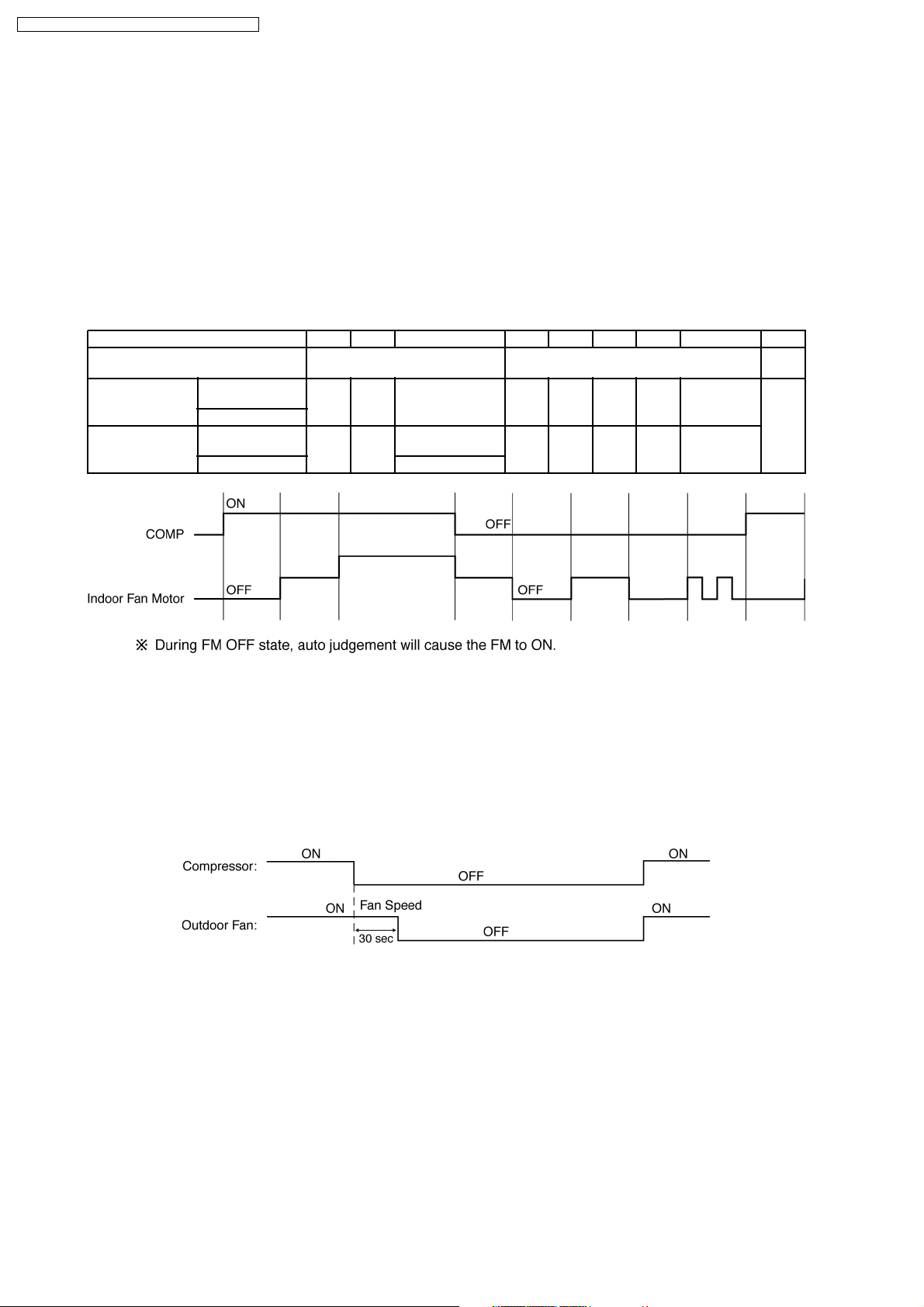
D. Deodorizing Control
i. Control conditio n
Control at cooling/dry operation and auto fan speed.
No Deodorizing Control is performed during ON timer standby operation and during Anti-freezing control prevention.
ii. Operation
The odor status is arranged as below and it is shifted as follow.
* When COMP is ON 1→2→3
(Shift to 4 when COMP is OFF)
* When COMP is OFF 4→5→6→7→6
(Shift to 1 when COMP is ON)
* Start from 4 if the Thermostat is OFF during the start operation.
Odor Status 1 2 3 4 5 6 7 6.7.6... 1
Status Shift
according to COMP
Status Shift
according
to time (s) Dry zone ON
Fan Speed
Cooling
zone
Cooling
zone
Dry zone SLo
40 50 — 30 90 20 90 20.90.20...
OFF SSLo
ON OFF ON
Auto Fan Speed
SSLo OFF SSLo OFF SSLo.OFF...
←→
7
8.1.8. Outdoor Fan Motor Operation
Outdoor fan motor is operated with one fan speed only. It starts when compressor starts operation and it stops 30 seconds after
compressor stops operation.
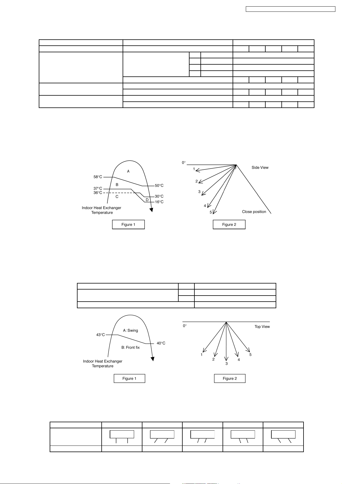
8.1.9. Airflow Direction
1. There are two types of airflow, vertical airflow (directed by horizontal vane) and horizontal airflow (directed by vertical vanes).
2. Control of airflow direction can be automatic (angles of direction is determined by operation mode, heat exchanger temperature
and intake air temperature) and manual (angles of direction can be adjusted using remote control).
28
CS-E9DKDW CU-E9DKD / CS-E12DKD W CU-E12DKD
8.1.9.1. Vertical Airflow
Operation Mode Airflow Direction Vane Angle (°)
1 2 3 4 5
Heating Auto with Heat Exchanger A Upward fix 3
Temperature B Downward fix 64
C Upward fix 3
D Downward fix 3
Manual 3 17 33 49 63
Cooling, Soft Dry and Ion Auto 8~36
Manual 8 15 22 30 36
Mode Judgment in Auto Auto 8
Manual 8 15 22 30 36
1. Automatic vertical airflow direction can be set using remote control; the vane swings up and down within the angles as stated
above. For heating mode operation, the angle of the vane depend s on the indoor heat exchanger temperature as Figure 1
below. When the air conditioner is stopped using remote control, the vane will shift to close position.
2. Manual vertical airflow direction can be set using remote control; the angles of the vane are as stated above and the positions
of the vane are as Figure 2 below. When the air conditioner is stopped using remote control, the vane will shift to close position.
8.1.9.2. Horizontal Airflow
1. Automatic horizontal airflow direction can be set using remote control; the vane swings left and right within the angles as stated
below. For heating mode operation, the angle of the vane depends on the indoor heat exchanger temperature as Figure 1
below.
Operation Mode Vane Angle (°)
Heating, with heat exchanger temperature A 65 ~ 115
B 90
Cooling, Soft Dry and Ion 65 ~ 115
2. Manual horizontal airflow direction can be set using remote control; the angles of the vane are as stated below and the positions
of the vane are as Figure 2 above.
Pattern 1 2 3 4 5
Airflow Direction
Patterns at Remote
Control
Vane Angle (°) 90 65 78 102 115
29

CS-E9DKDW CU-E9DKD / CS-E12DKD W CU-E12DKD
8.1.10. Quiet operation (Cooling Mode/Cooling area of Dry Mode)
A. Purpose
To provide quiet cooling operation compare to normal operation.
B. Control condition
a. Quiet operation start condition
When “quiet” button at remote control is pressed.
•
Quiet LED illuminates.
b. Quiet operation stop condition
1. When one of the followin g conditions is satisfied, quiet operation stops:
a. Powerful button is pressed.
b. Stop by OFF/ON switch.
c. Timer “off” activates.
d. Quiet button is pressed again.
2. When quiet operation is stopped, operation is shifted to normal operation with previous setting.
3. When fan speed is changed, quiet operation is shifted to quiet operation of the new fan speed.
4. When operation mode is changed, quiet operation is shifted to quiet operation of the new mode.
5. During quiet operation, if timer “on” activates, quiet operation maintains.
6. After off, when on back, quiet operation is not memorised.
C. Control contents
1. Fan speed is changed from normal setting to quiet setting of respective fan speed.
This is to reduce sound of Hi, Me, Lo for 3dB.
2. Fan speed for quiet operation is -1 step from setting fan speed.
8.1.10.1. Quiet operation (Heating)
A. Purpose
To provide quiet heating operation compare to normal operation.
B. Control condition
a. Quiet operation start condition
When “quiet” button at remote control is pressed.
•
Quiet LED illuminates.
b. Quiet operation stop condition
1. When one of the followin g conditions is satisfied, quiet operation stops:
a. Powerful button is pressed.
b. Stop by OFF/ON switch.
c. Timer “off” activates.
d. Quiet button is pressed again.
2. When quiet operation is stopped, operation is shifted to normal operation with previous setting.
3. When fan speed is changed, quiet operation is shifted to quiet operation of the new fan speed.
4. When operation mode is changed, quiet operation is shifted to quiet operation of the new mode, except fan only mode.
5. During quiet operation, if timer “on” activates, quiet operation maintains.
6. After off, when on back, quiet operation is not memorised.
30
 Loading...