

Page 1
Order No. MAC0301013S1
Room Air Conditioner
CS-A9CKPG CU-A9CKP6G
CS-A12CKPG CU-A12CKP6G
E25
Subject :
Revision
Please file and use this supplement manual together with the service manual for Model No. CS-A9CKPG/
CU-A9CKP6G, CS-A12CKPG/CU-A12CKP6G, Order No. MAC0211070C1.
CONTENTS
Page Page
1 Features 2
2 Functions
3 Product Specifications
4 Dimensions
5 Refrigeration Cycle Diagram
6 Block Diagram
7 Wiring Diagram
8 Operation Details
9 Operating Instructions (U.S.A. Models)
10 Operating Instructions (Canada Models)
11 Installation Instructions 45
12 2-way, 3-way Valve
3
6
13 Servicing Information
10
14 Troubleshooting Guide
15 Technical Data
12
13
16 Exploded View
17 Replacement Parts List
14
15
18 Exploded View
35
19 Replacement Parts List
20 Electronic Circuit Diagram
40
55
62
66
68
71
72
73
74
75
© 2003 Matsushita Industrial Corp. Sdn. Bhd.
(11969-T). All rights reserved. Unauthorized copying
and distribution is a violation of law.
Page 2

−
−
−
−
−
−
−
CS-A9CKPG CU-A9CKP6G / CS-A12CKPG CU-A12CKP6G
1 Features
High Efficiency
•
Compact Design
•
Comfort Environment
•
Air filter with function to reduce dust and smoke
−
Wider range of horizontal discharge air
−
Auto Restart
•
Random auto restart after power failure for safety restart
−
operation
Removable and Washable Front Panel
•
Remote Control Self-illuminating Button
•
Air Purifying Filter
•
Trap dust, tobacco smoke and tiny particles
−
Prevent the growth of bacteria and viruses trapped
−
Solar Refreshing Deodorizing Filter
•
Remove unpleasant odour from the air
−
Quality Improvement
•
Gas leakage protection
−
Prevent compressor reverse cycle
−
OLP to protect compressor
−
Noise prevention during soft dry operation
−
Compressor Protection Control (Cooling & Soft Dry)
−
Overload Protection Control (Heating)
−
Outdoor Fan Control
−
Compressor High Pressure Control
−
Blue Coated Condenser
−
High resistance to corrosion
−
Low Outdoor Ambient Temperature Control
−
Operation Improvement
•
Quiet mode to provide extra quiet operation
−
Powerful mode to reach the desired room temperature
−
quickly
Economy mode to reduce electrical power consumption
−
Long Installation Piping
•
CS/CU-A9CK, long piping up to 10 meter (393.7 inch)
−
CS/CU-A12CK, long piping up to 15 mete r (590.6 inch)
−
24-hour Timer Setting
•
2
Page 3

2 Functions
Remote Control
CS-A9CKPG CU-A9CKP6G / CS-A12CKPG CU-A12CKP6G
Self illuminating
button
OFF / ON I
MODE
FAN SPEED
AIR SWING
POWERFUL
QUIET
Operation OFF / ON
Operation Mode Selection
•
AUTO
HEAT
•
COOL
•
•
DRY
Automatic Operation Mode
Heating Operation Mode
Cooling Operation Mode
Soft Dry Operation Mode
Indoor Fan Speed Selection
•
FAN
Low Fan Speed
•
FAN
Medium Fan Speed
FAN
High Fan Speed
•
•
AUTO
FAN
Automatic Fan Speed
Vertical Airflow Direction Control
•
AUTO
Automatic Vertical Airflow
Direction Control
•
MANUAL
Vertical Airflow Direction
Manual Control (5 stages of
adjustment)
Powerful Mode Operation OFF/ON
Quiet Mode Operation OFF/ON
TEMP.
ON-TIMER
OFF-TIMER
TIME
SET
CANCEL
CLOCK
ECONOMY
Room Temperature Setting
Heating, Cooling, Soft Dry Operation.
• Temperature Setting (16°C [60.8°F] to
30°C [86°F])
Automatic Operation
•
Operation with 2°C (35.6°F) higher
than standard temperature.
• Operation with standard temperature.
•
Operation with 2°C (35.6°F) lower
than standard temperature.
Timer Operation Selection
• 24-hour, OFF / ON Real Timer Setting.
Time / Timer Setting
• Hours and minutes setting.
Timer Operation Set / Cancel
• ON Timer and OFF Timer setting and
cancellation.
Clock Setting
• Current time setting.
Economy Operation OFF / ON
3
Page 4
CS-A9CKPG CU-A9CKP6G / CS-A12CKPG CU-A12CKP6G
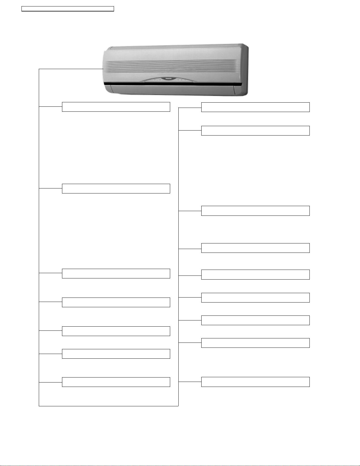
Indoor Unit
AUTO
OFF / ON
Automatic Operation Button
• Press for < 5s to operate Automatic
operation mode.
(Used when the remote control cannot be used.)
• Press continuously for 5s or < 10s to
operate Test Run/Pump down. “Beep”
sound will be heard at the 5th second.
(Used when test running or servicing.)
• Press continuously for 10s and above to
omit or resume the remote control signal
receiving sound. “Beep, beep” sound will
be heard at the 10th second.
Operation Indication Lamps (LED)
•
POWER
(Green) .........Lights up in operation,
•
QUIET
(Orange) .........Lights up in Quiet Mode
•
TIMER
(Orange).........Lights up in Timer
•
POWERFUL
•
ECONOMY
(Orange)...Lights up in Powerful
(Green) ...... Lights up in Economy
blinks in Automatic
Operation Mode judging.
Operation.
Setting.
Mode Operation.
Mode Operation.
Economy Operation
• To reduce electrical power consumption.
Indoor Fan Speed Control
• High, Medium and Low.
• Automatic Fan Speed Mode
– Heating : Fan speed varies from Me →
SSLo in accordance with
indoor heat exchanger.
– Cooling : Fan rotates at Hi, Me and SLo
speed. Deodorizing control is
available.
– Soft Dry : Fan rotates at Lo- speed.
Deodorizing control is
available.
Airflow Direction Control
• Automatic air swing and manual adjusted
by remote control for vertical airflow.
• Manually adjusted by hand for horizontal
airflow.
Starting Current Control
• Fan motor is delayed for 1.6 seconds when
compressor starts simultaneously.
Operation Mode
• Heating, Cooling, Soft Dry and Automatic
Mode.
Powerful Operation
• Reaches the desired room temperature
quickly.
Quiet Operation
• To provide extra quiet operation.
Random Auto Restart Control
• Operation is restarted randomly after power
failure at previous setting mode.
Anti-Freezing Control
• Anti-Freezing control for indoor heat
exchanger. (Cooling and Soft Dry)
Time Delay Safety Control
•
Restarting is inhibited for appro. 3 minutes.
7 Minutes Time Save Control
• Cooling Operation only.
30 Minutes Time Save Control
• Heating Operation only.
Hot-Start Control
• At Heating Operation the indoor fan will
operate at SLo speed when indoor heat
exchanger temperature reaches 30°C
(86°F).
Anti Cold Draft Control
• The indoor fan operates at SSLo when the
indoor heat exchanger temperature is low.
(During Heating mode thermal off)
4
Page 5
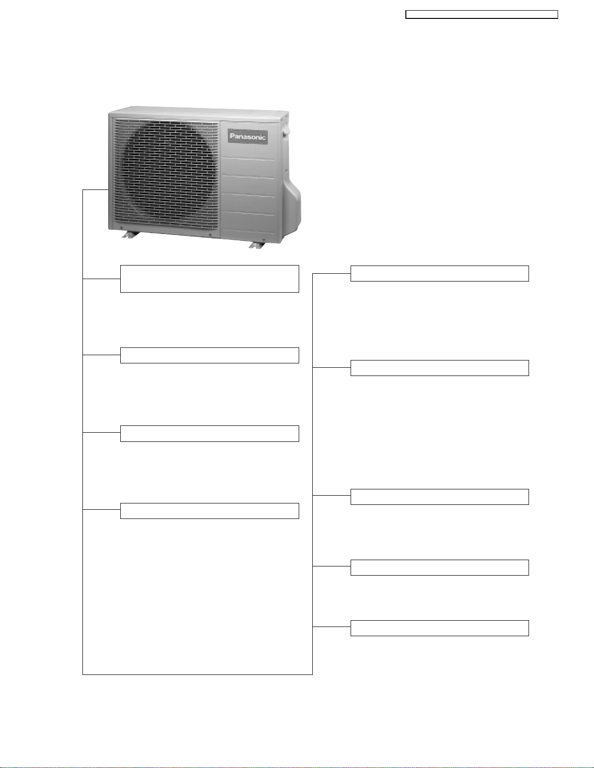
Outdoor Unit
CS-A9CKPG CU-A9CKP6G / CS-A12CKPG CU-A12CKP6G
Compressor Reverse Rotation
Protection Control
• To protect compressor from reverse
rotation when there is a instantaneous
power failure.
Overload Protector
• OLP to protect the compressor. Overload
Protector will trip when
– High temperature or high current flows
to compressor.
60 Secs. Forced Operation Control
• Once the compressor is activated, it
does not stop within the first 60 secs.
However, it stops immediately with
remote control stop signal.
Outdoor Fan Operation Control
• Temperature Fuse.
Deice Control
• To prevent frosting at outdoor heat
exchanger. (Only for Heating Operation)
•
Temperature of outdoor heat exchanger
is sensed by TRS (Thermal Reed Switch).
TRS OFF temperature 4°C (39.2°F).
TRS ON temperature -3°C (26.6°F).
Overload Protection Control
• Outdoor fan stops when indoor heat
exchanger temperature rises to 51°C
(123.8°F) and above, and restarts when
the indoor heat exchanger temperature
drops to 49°C (120.2°F) and below.
• Compressor stop when indoor heat
exchanger temperature reaches 65°C
(149°F) or above. (Heating Operation
Only)
Compressor Protection Control
• If the outdoor fan motor is not running
after compressor starts for 50 secs.,
compressor will stop. (Cooling and Soft
Dry Operation only).
4-Way Valve Control
• When the unit is switched to “OFF”
during Heating Operation, 4-way valve
stays at Heating position for 5 minutes.
Low Ambient Temperature Control
• To protect air conditioner from damage
under the low outdoor ambient
temperature < -10°C (14°F).
5
Page 6
CS-A9CKPG CU-A9CKP6G / CS-A12CKPG CU-A12CKP6G
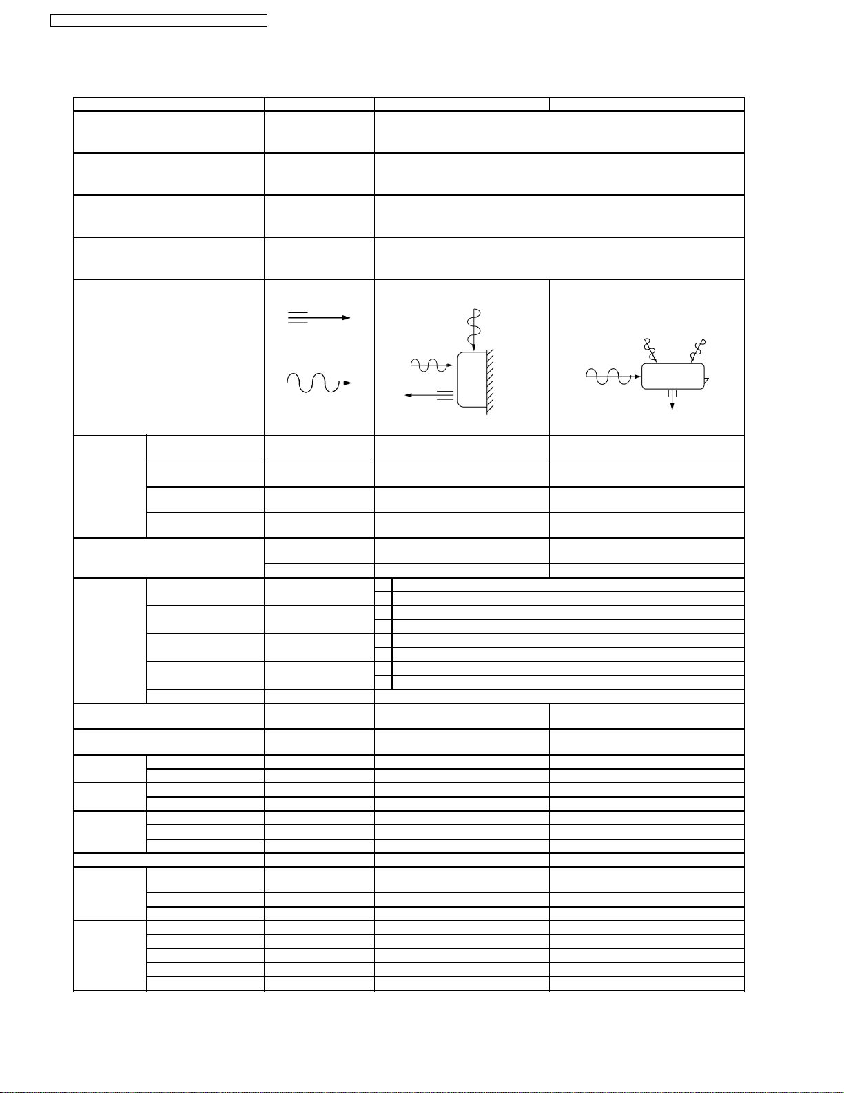
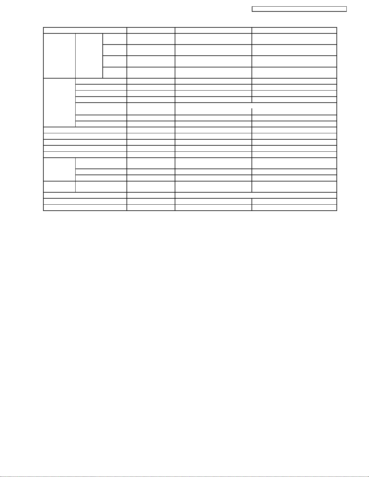
3 Product Specifications
Unit CS-A9CK CU-A9CK
Power Source Phase, Voltage, Cycle Single, 115, 60 Hz
Cooling Capacity kW (BTU/h) 2.40 (8,200)
Heating Capacity kW (BTU/h) 2.70 (9,200)
Moisture Removal l/h (Pint/h) 0.7 (1.5)
Airflow Method OUTLET
INTAKE
Air Volume Indoor Air (Lo) m3/min (cfm) Cooling; 6.1 (220)
Indoor Air (Me) m3/min (cfm) Cooling; 7.5 (260)
Indoor Air (Hi) m3/min (cfm) Cooling; 8.9 (310)
Indoor Air (SHi) m3/min (cfm) Cooling; 9.6 (340)
Noise Level dB (A) Cooling; High 36, Low 26
Power level dB — —
Electrical Data Input Power W (1) Cooling; 810, Heating; 730
(2) Cooling; 800, Heating; 700
Running Current A (1) Cooling; 7.4, Heating; 6.7
(2) Cooling; 7.3, Heating; 6.5
EER W/W (BTU/hW) (1) Cooling; 2.960 (10.12)
(2) Cooling; 3.00 (10.25)
COP W/W (BTU/hW) (1) Heating; 3.70 (12.60)
(2) Heating; 3.85 (13.10)
Starting Current A 42.0
Piping Connection Port
(Flare piping)
Pipe Size
(Flare piping)
Drain
Hose
Power Cord Length m — —
Dimensions Height inch (mm) 10 - 13/16 (275) 21 - 1/4 (540)
Net Weight lb (kg) 20 (9.0) 68 (31.0)
Compressor Type — Rotary (1 cylinder)
Air Circulation Type Cross-flow Fan Propeller Fan
Inner diameter mm (inch) 12 (0.47) —
Length mm (inch) 650 (25.59) —
Number of core-wire — —
Width inch (mm) 31 - 15/32 (799) 30 - 23/32 (780)
Depth inch (mm) 8 - 9/32 (210) 11 - 3/8 (289)
Motor Type — Induction (2-poles)
Rated Output W — 600
Material AS + Glass Fiber 20% PP Resin
Motor Type Induction (4-poles) Induction (6-poles)
Input W 55.1 78.0
Rated Output W 15 30
inch
inch
inch
inch
SIDE VIEW TOP VIEW
Heating; 6.7 (240)
Heating; 7.6 (270)
Heating; 9.8 (350)
Heating; 9.8 (350)
Heating; High 38, Low 28
G ; Half Union 3/8”
L ; Half Union 1/4”
G ; (gas side) 3/8”
L ; (liquid side) 1/4”
—
—
Cooling; 35.6 (1,260)
—
Cooling; High 49
Heating; High 49
G ; 3-way valve 3/8”
L ; 2-way valve 1/4”
G ; (gas side) 3/8”
L ; (liquid side) 1/4”
rolling piston type
6
Page 7
CS-A9CKPG CU-A9CKP6G / CS-A12CKPG CU-A12CKP6G
Unit CS-A9CK CU-A9CK
Fan Speed Low rpm Cooling; 780
Medium rpm Cooling; 960
High rpm Cooling; 1,140
SuperHigh rpm Cooling; 1,230
Heat
Exchanger
Refrigerant Control Device — Capillary Tube
Refrigeration Oil (cm3) — SUNISO 4GSI (290)
Refrigerant (R-22) g (oz) — 870 (30.7)
Thermostat Electronic Control —
Protection Device — Overload Protector
Capillary Tube Length mm (inch) — Cooling; 982 (38.66),
Air Filter Material
Capacity Control Capillary Tube
Compressor Capacitor µF, VAC — 35 µF, 370VAC
Fan Motor Capacitor µF, VAC 5.0 µF, 230VAC 8.0 µF, 230VAC
Description Evaporator Condenser
Tube material Copper Copper
Fin material Aluminium (Pre Coat) Aluminium (Blue Coat)
Fin Type Slit Fin Corrugate Fin
Row / Stage (Plate fin configuration, forced draft)
FPI 19 16
Size (W × H × L) mm (inch) 610 (24.02) × 315 (12.40) × 25.4 (1) 841 (33.11) × 508 (20) × 22 (0.87)
Flow Rate l/min — Cooling; 5.4, Heating; 15.5
Inner Diameter mm (inch) — Cooling; 1.2 (0.05), Heating; 1.5 (0.06)
Style
Heating; 840
Heating; 960
Heating; 1,230
Heating; 1,230
2×15 1×20
Heating; 305 (12.01)
P.P.
Honeycomb
—
—
845
—
—
Note:
•
Specifications are subject to change without notice for further improvement.
•
(1) — CS-A9CKPG-4 / CU-A9CKP6G-4 (USA).
•
(2) — CS-A9CKPG-5 / CU-A9CKP6G-5 (Canada).
7
Page 8
CS-A9CKPG CU-A9CKP6G / CS-A12CKPG CU-A12CKP6G
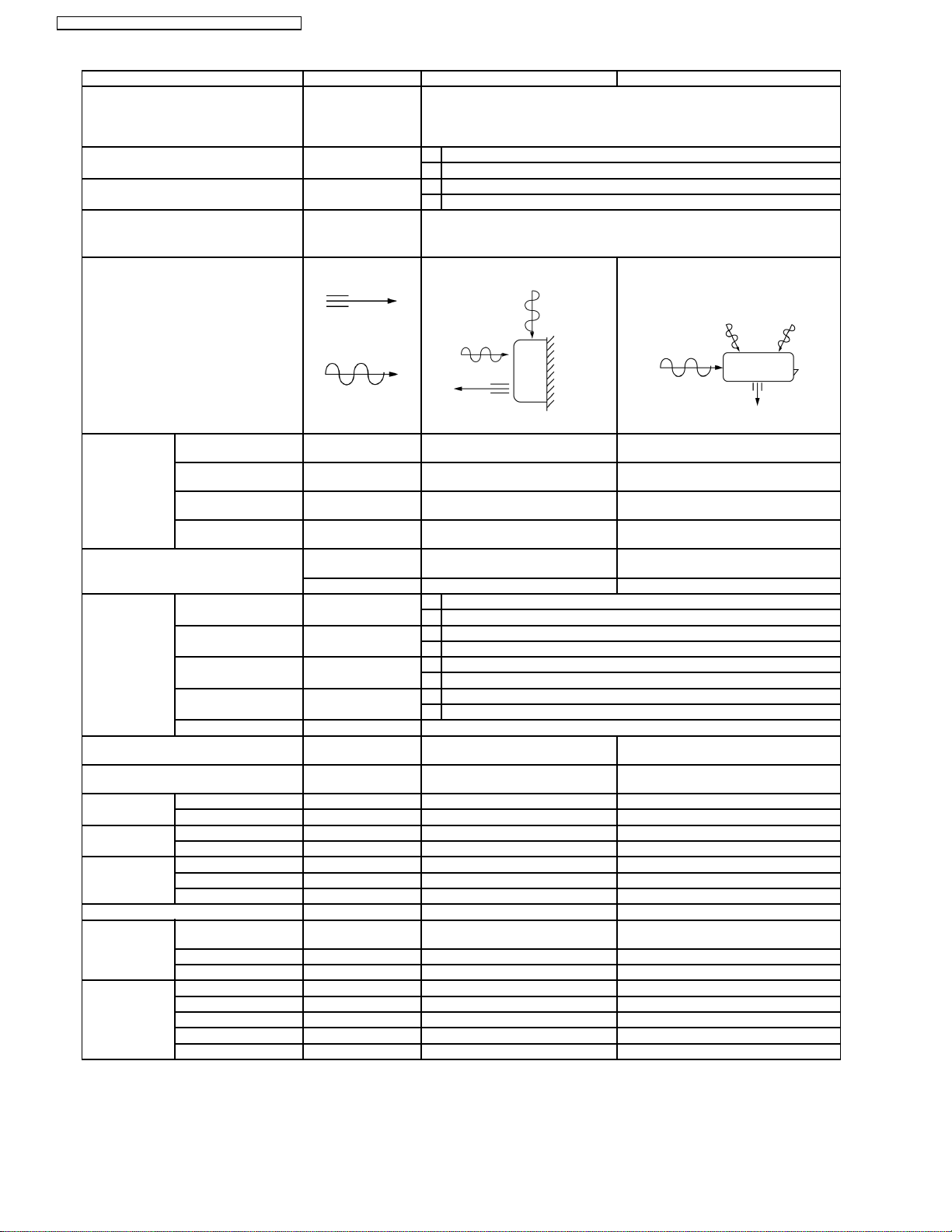
Unit CS-A12CK CU-A12CK
Power Source Phase, Voltage,
Single, 115, 60 Hz
Cycle
Cooling Capacity kW (BTU/h) (1) 3.51 (12,000)
(2) 3.50 (12,000)
Heating Capacity kW (BTU/h) (1) 3.96 (13,500)
(2) 4.00 (13,500)
Moisture Removal l/h (Pint/h) 1.3 (2.7)
Airflow Method OUTLET
SIDE VIEW TOP VIEW
INTAKE
Air Volume Indoor Air (Lo) m3/min (cfm) Cooling; 6.9 (250)
—
Heating; 7.4 (260)
Indoor Air (Me) m3/min (cfm) Cooling; 8.6 (300)
—
Heating; 8.6 (300)
Indoor Air (Hi) m3/min (cfm) Cooling; 9.7 (340)
Cooling; 33.1 (1,170)
Heating; 10.2 (360)
Indoor Air (SHi) m3/min (cfm) Cooling; 10.0 (350)
—
Heating; 10.0 (350)
Noise Level dB (A) Cooling; High 39, Low 29
Heating; High 40, Low 29
Cooling; High 49
Heating; High 49
Power level dB — —
Electrical Data Input Power W (1) Cooling; 1,200, Heating; 1,190
(2) Cooling; 1,200, Heating; 1,200
Running Current A (1) Cooling; 10.6, Heating; 10.5
(2) Cooling; 10.6, Heating; 10.6
EER W/W (BTU/hW) (1) Cooling; 2.925 (10.00)
(2) Cooling; 2.90 (10.00)
COP W/W (BTU/hW) (1) Heating; 3.330 (11.34)
(2) Heating; 3.35 (11.25)
Starting Current A 57.0
Piping Connection Port
(Flare piping)
Pipe Size
(Flare piping)
Drain
Hose
Inner diameter mm (inch) 12 (0.47) —
Length mm (inch) 650 (25.59) —
inch
inch
inch
inch
G ; Half Union 1/2”
L ; Half Union 1/4”
G ; (gas side) 1/2”
L ; (liquid side) 1/4”
G ; 3-way valve 1/2”
L ; 2-way valve 1/4”
G ; (gas side) 1/2”
L ; (liquid side) 1/4”
Power Cord Length m — —
Number of core-wire — —
Dimensions Height inch (mm) 10 - 13/16 (275) 21 - 1/4 (540)
Width inch (mm) 31 - 15/32 (799) 30 - 23/32 (780)
Depth inch (mm) 8 - 9/32 (210) 11 - 3/8 (289)
Net Weight lb (kg) 20 (9.0) 77 (35.0)
Compressor Type — Rotary (1 cylinder)
rolling piston type
Motor Type — Induction (2-poles)
Rated Output W — 850
Air Circulation Type Cross-flow Fan Propeller Fan
Material AS + Glass Fiber 20% PP Resin
Motor Type Induction (4-poles) Induction (6-poles)
Input W 55.1 78.0
Rated Output W 15 30
8
Page 9
CS-A9CKPG CU-A9CKP6G / CS-A12CKPG CU-A12CKP6G
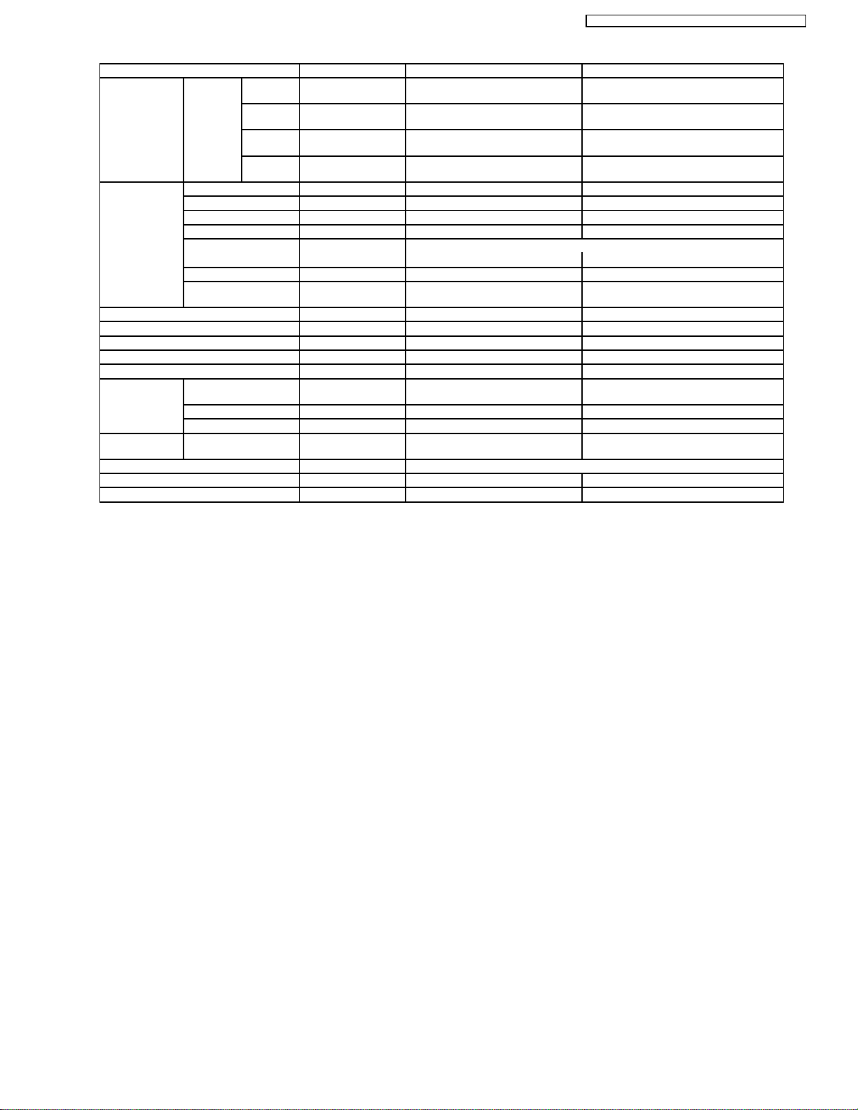
Unit CS-A12CK CU-A12CK
Fan Speed Low rpm Cooling; 900
Medium rpm Cooling; 1,120
High rpm Cooling; 1,260
SuperHigh rpm Cooling; 1,300
Heat Exchanger Description Evaporator Condenser
Tube material Copper Copper
Fin material Aluminium (Pre Coat) Aluminium (Blue Coat)
Fin Type Slit Fin Corrugate Fin
Row / Stage (Plate fin configuration, forced draft)
FPI 21 16
Size (W × H × L) mm (inch) 610 (24.02) × 315 (12.40) × 25.4 (1) 735.1 (28.94)
Refrigerant Control Device — Capillary Tube
Refrigeration Oil (cm3) — SUNISO 4GSI (350)
Refrigerant (R-22) kg (oz) — 1.04 (36.7)
Thermostat Electronic Control —
Protection Device — Overload Protector
Capillary Tube Length mm — Cooling; 530 (20.87),
Flow Rate l/min — Cooling; 7.0, Heating; 13.4
Inner Diameter mm — Cooling; 1.2 (0.05), Heating; 1.4 (0.06)
Air Filter Material
Style
Capacity Control Capillary Tube
Compressor Capacitor µF, VAC — 50 µF, 370VAC
Fan Motor Capacitor µF, VAC 5.0 µF, 230VAC 8.0 µF, 230VAC
Heating; 960
Heating; 1,120
Heating; 1,300
Heating; 1,300
2×15 2×24
705.8 (27.79)
Heating; 325 (12.80)
P.P.
Honeycomb
—
—
850
—
× 508 (20) × 36.38 (1.43)
—
Note:
•
Specifications are subject to change without notice for further improvement.
•
(1) — CS-A12CKPG-4 / CU-A12CKP6G-4 (USA).
•
(2) — CS-A12CKPG-5 / CU-A12CKP6G-5 (Canada).
9
Page 10
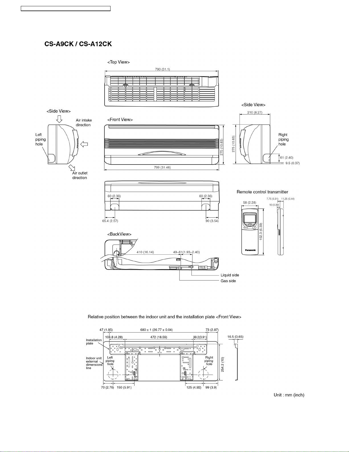
CS-A9CKPG CU-A9CKP6G / CS-A12CKPG CU-A12CKP6G
4 Dimensions
10
Page 11
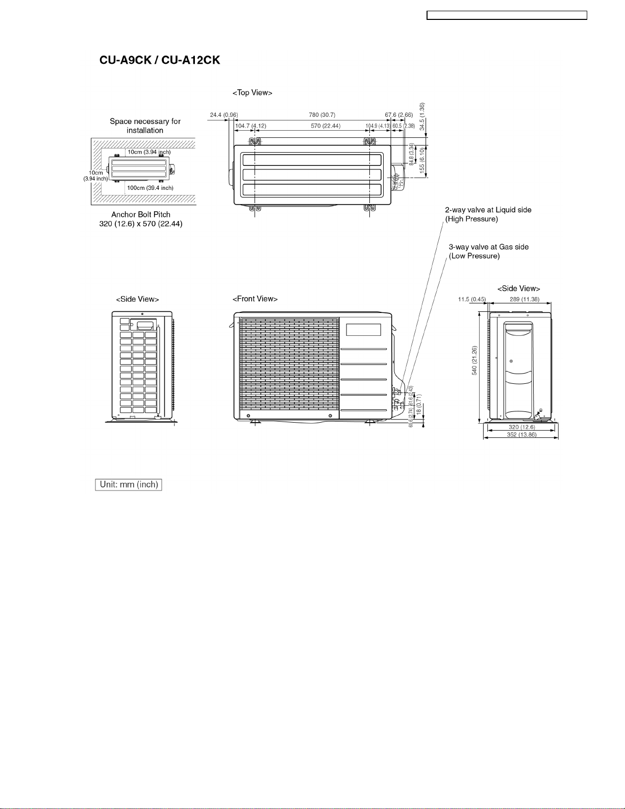
CS-A9CKPG CU-A9CKP6G / CS-A12CKPG CU-A12CKP6G
11
Page 12
CS-A9CKPG CU-A9CKP6G / CS-A12CKPG CU-A12CKP6G
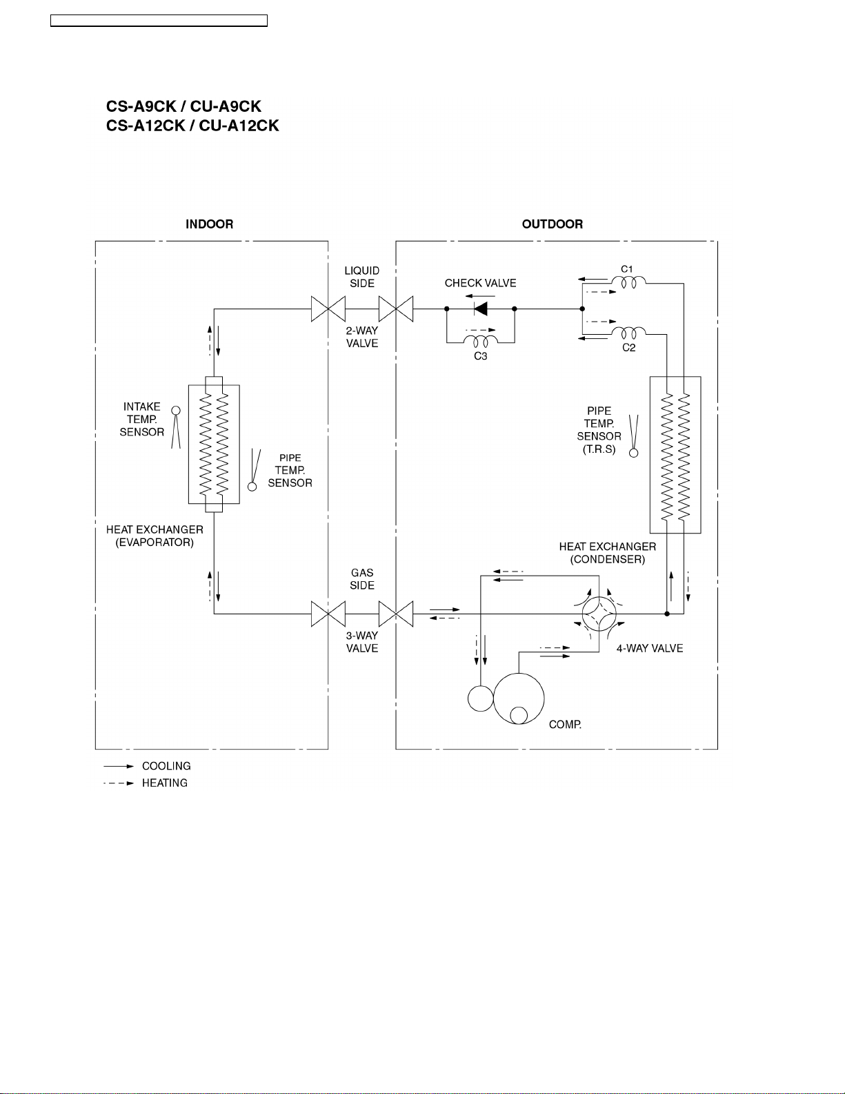
5 Refrigeration Cycle Diagram
12
Page 13
6 Block Diagram
CS-A9CKPG CU-A9CKP6G / CS-A12CKPG CU-A12CKP6G
13
Page 14
CS-A9CKPG CU-A9CKP6G / CS-A12CKPG CU-A12CKP6G
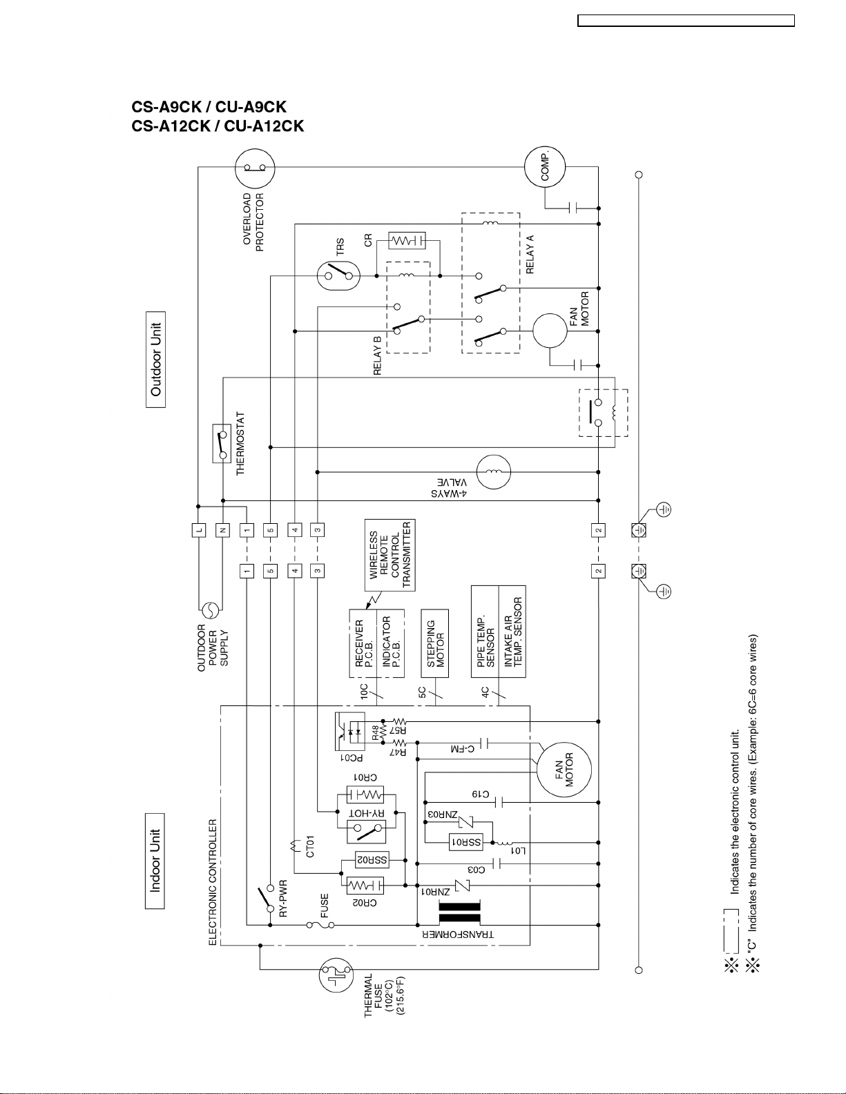
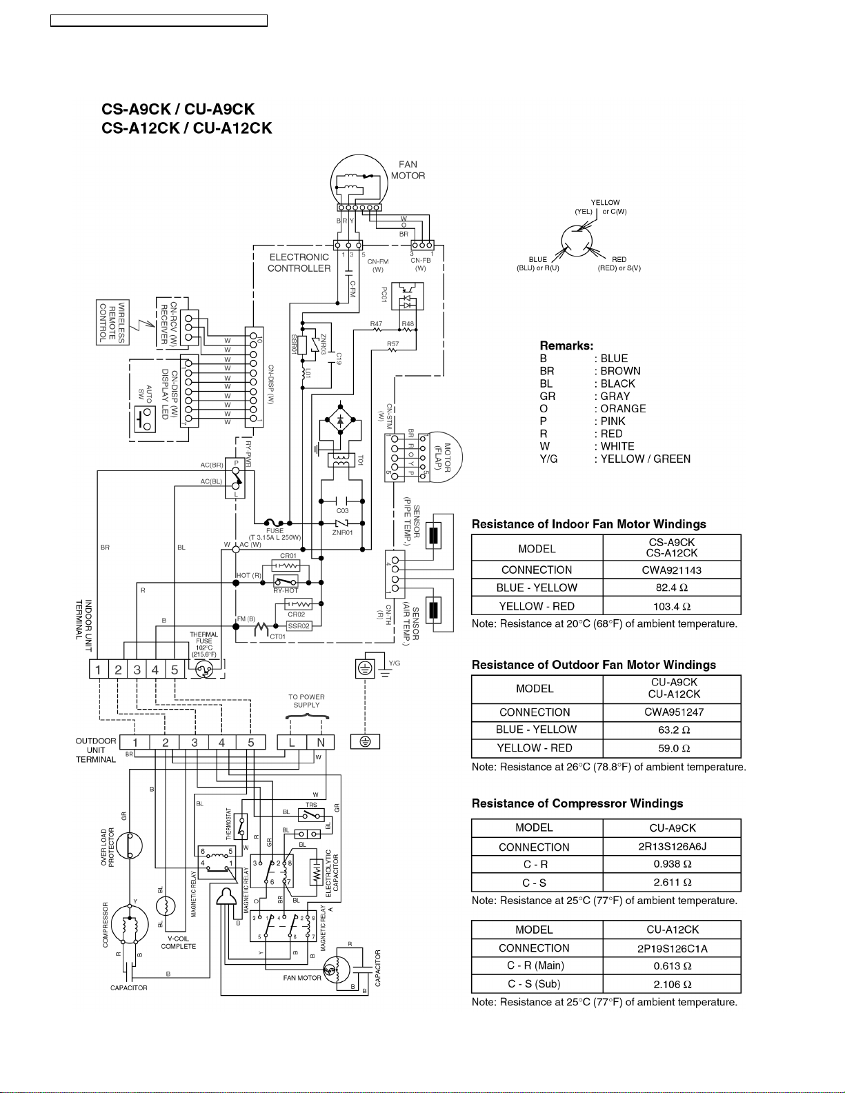
7 Wiring Diagram
14
Page 15
CS-A9CKPG CU-A9CKP6G / CS-A12CKPG CU-A12CKP6G
8 Operation Details
8.1. Cooling Mode Operation
Cooling in operation according to Remote Control setting.
Time Delay Safety Control (3 minutes)
When the compressor is stopped by Remote Control, it restarts after 3 minutes when it is turned ON by Remote Control.
•
When the setting temperature is reached during cooling operation, the compressor stops and it will not start for 3 minutes.
•
7 minutes Time Save Control
The compressor will start automatically if it has stopped for 7 minutes even if the room temperature is between the compressor
•
ON temperature and OFF temperature.
Starting Current Control
When the compressor outdoor fan motor and indoor fan motor are simultaneously started, the indoor fan motor will operate 1.6
•
second later.
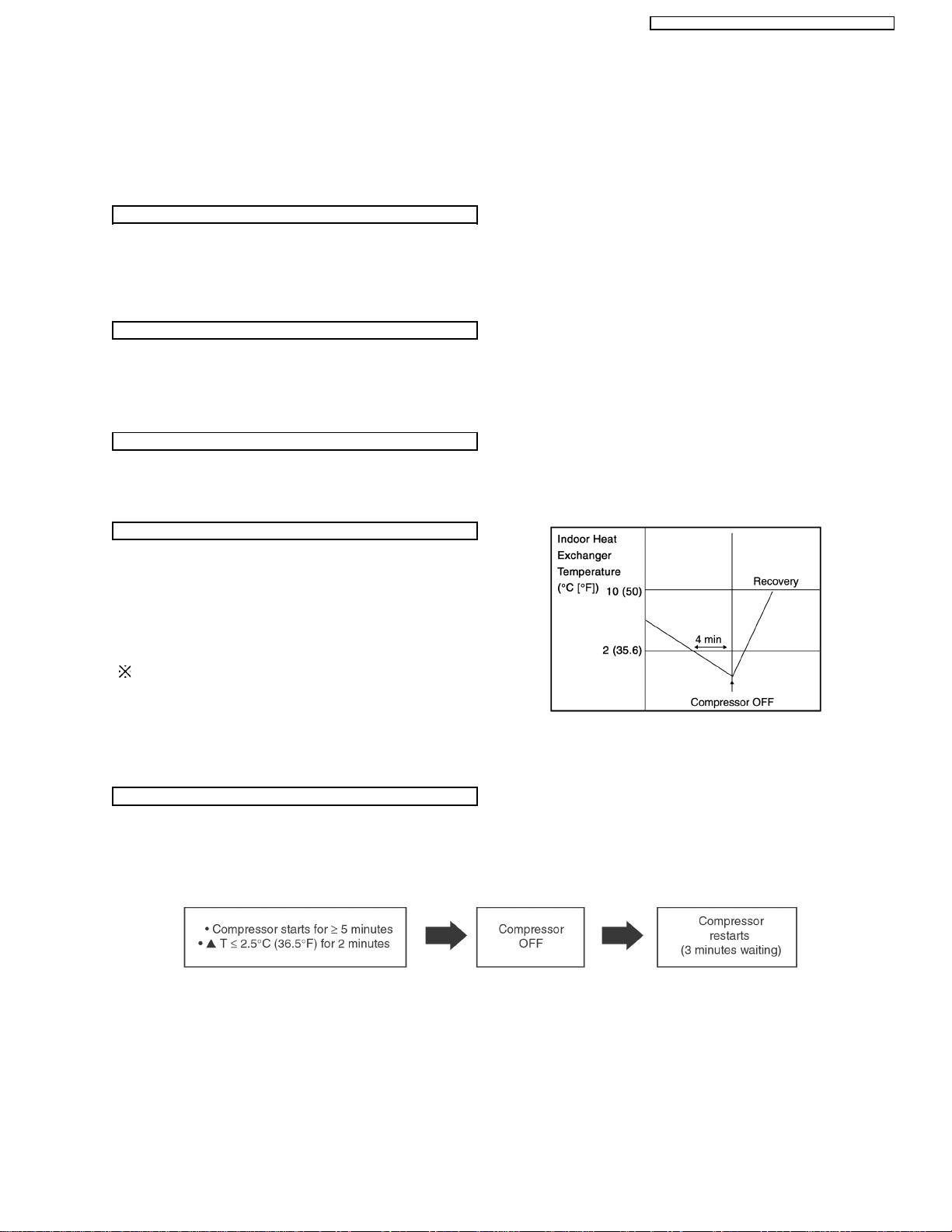
Anti-Freezing Control
If the temperature of the indoor heat exchanger falls
•
continuously below 2°C (35.6°F) for 4 minutes or more, the
compressor turns off to protect the indoor heat exchanger
from freezin g. The fan speed setting remains the same.
Compressor will restart again when the indoor heat
•
exchanger temperature rises to 10°C (50°F) (Recovery).
3 minutes waiting of Time Delay Safety Control is valid for
Cooling Operation.
Compressor Reverse Rotation Protection Control
If the compressor is operating continuously for 5 minutes or longer and the temperature difference between intake air and
•
indoor heat exchanger is 2.5°C (36.5°F) or less for 2 minutes, compressor will stop and restart automatically.
(Time Delay Safety Control is valid)
▲
T = Intake air temperature - Indoor heat exchanger temperature
This is to protect reverse rotation of the compressor when there is a instantaneous power failure.
15
Page 16
CS-A9CKPG CU-A9CKP6G / CS-A12CKPG CU-A12CKP6G
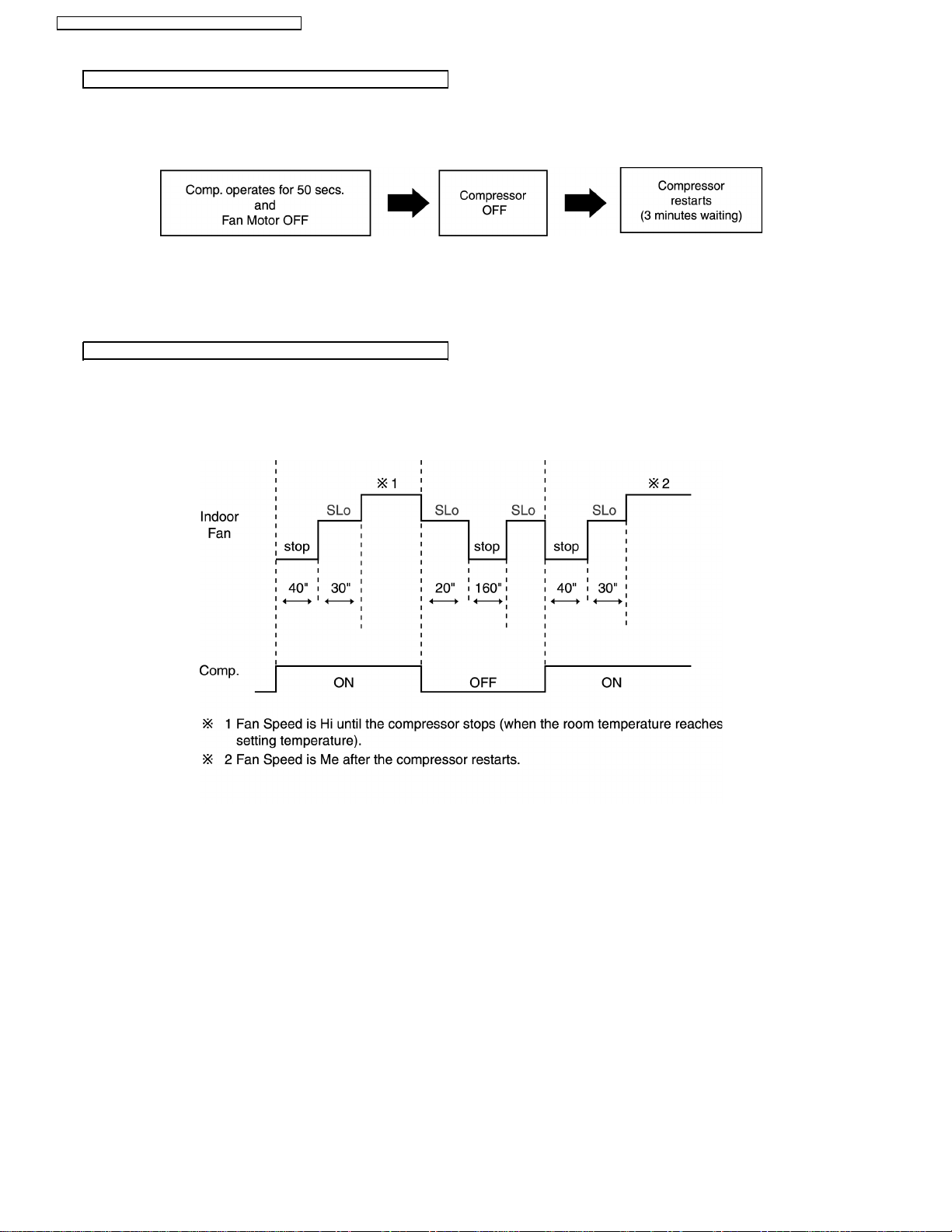
Compressor Protection Control
After the compressor starts for 50 seconds but the outdoor fan motor is still OFF, the compressor will stop and restart
•
automatically. (Time Delay Safety Control is valid).
If the above phenomenon is repeated for 3 times, the compressor will stop totally.
•
The above phenomenon is reset when there is a change to heating mode or stopped by Remote Control Switch.
•
Automatic Fan Speed Mode
When Automatic Fan Speed is selected at Remote Control during cooling operation.
Fan speed rotates in the range of Hi to Me.
•
Deodorizing Control.
•
16
Page 17
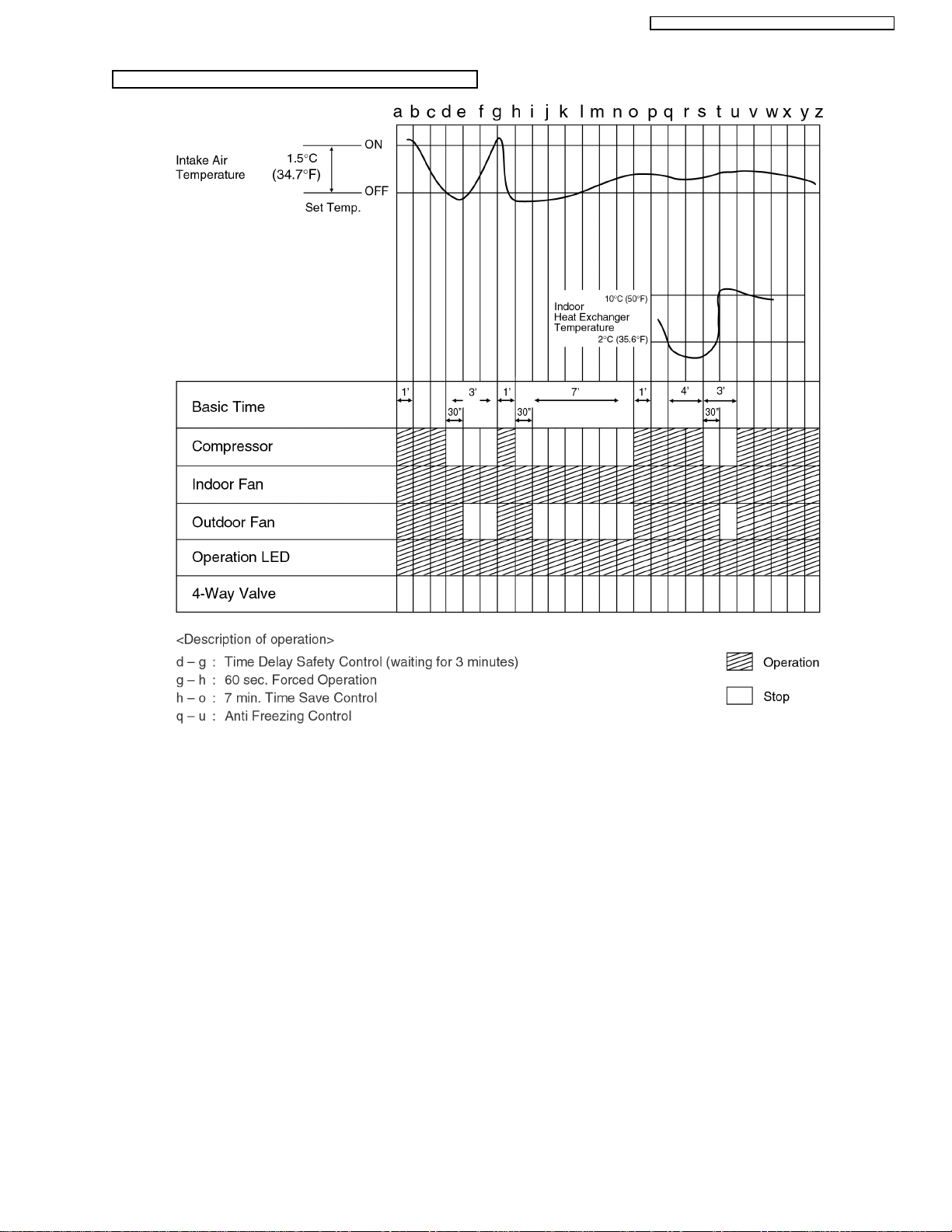
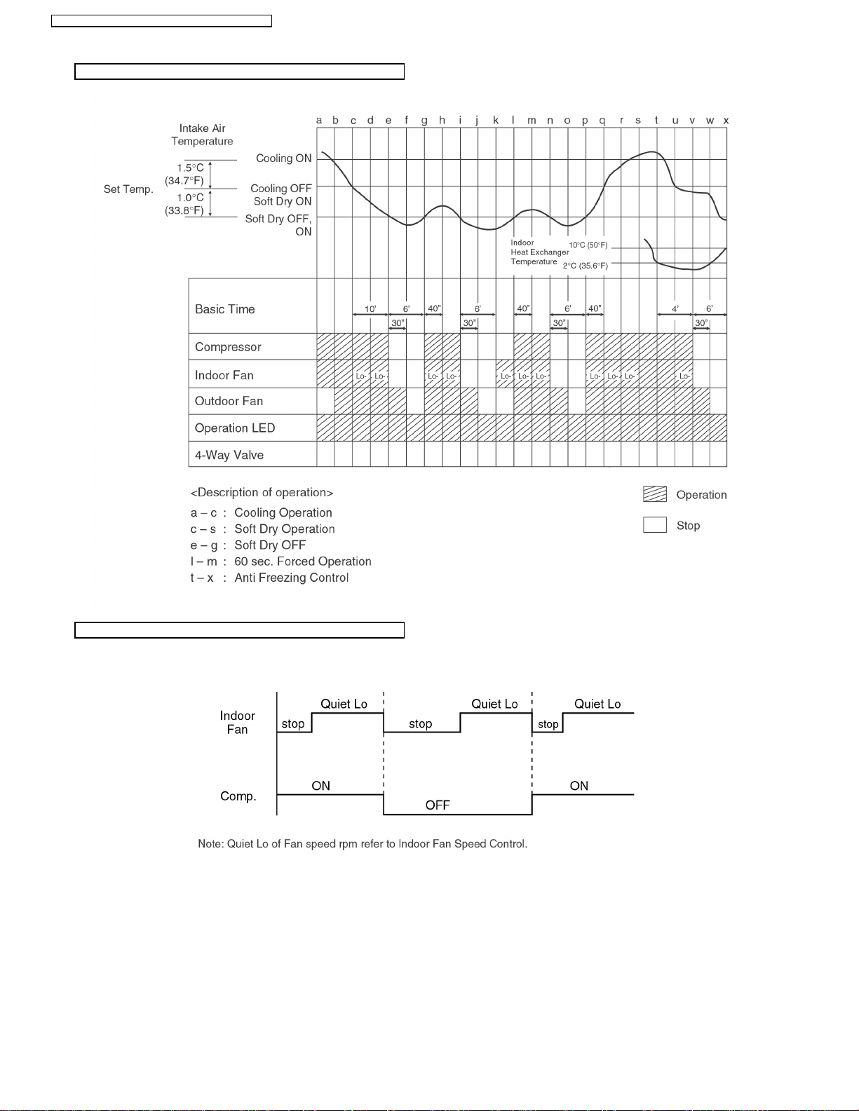
Cooling Operation Time Diagram
CS-A9CKPG CU-A9CKP6G / CS-A12CKPG CU-A12CKP6G
17
Page 18
CS-A9CKPG CU-A9CKP6G / CS-A12CKPG CU-A12CKP6G
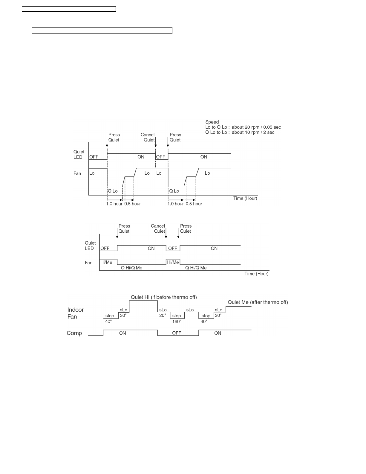
Quiet Operation Control
(For Cooling Mode or cooling region of Soft Dry Mode)
Purpose of this operation is to provide quite cooling operation compare to normal operation.
•
When the Quiet Mode is set at the remote control, Quiet Mode LED illuminates, the sound level will be automatically decreased
•
2 dB (Lo), decreased 3 dB (Hi, Me), against the present sound level operation.
Quiet setting of fan speed rpm refer to Indoor Fan Speed Control.
•
Dew formation become severe at Quiet Lo cool, therefore Quiet Lo cool is operated only 1h 30 min (1h QLo, 30 min QLo + 50).
•
After that, it goes back to Lo cool (However Quiet LED remains on).
Manual Airflow Direction:-
•
RPM control during Lo cool
−
RPM control during Hi & Me cool
−
Auto Airflow Direction:-
•
Quiet Mode Operation will stop if:-
•
Quiet mode button is pressed again.
−
Stopped by ON/OFF switch.
−
Timer OFF activates.
−
Powerful mode button is pressed.
−
When change mode to Air Circulation mode.
−
18
Page 19
CS-A9CKPG CU-A9CKP6G / CS-A12CKPG CU-A12CKP6G
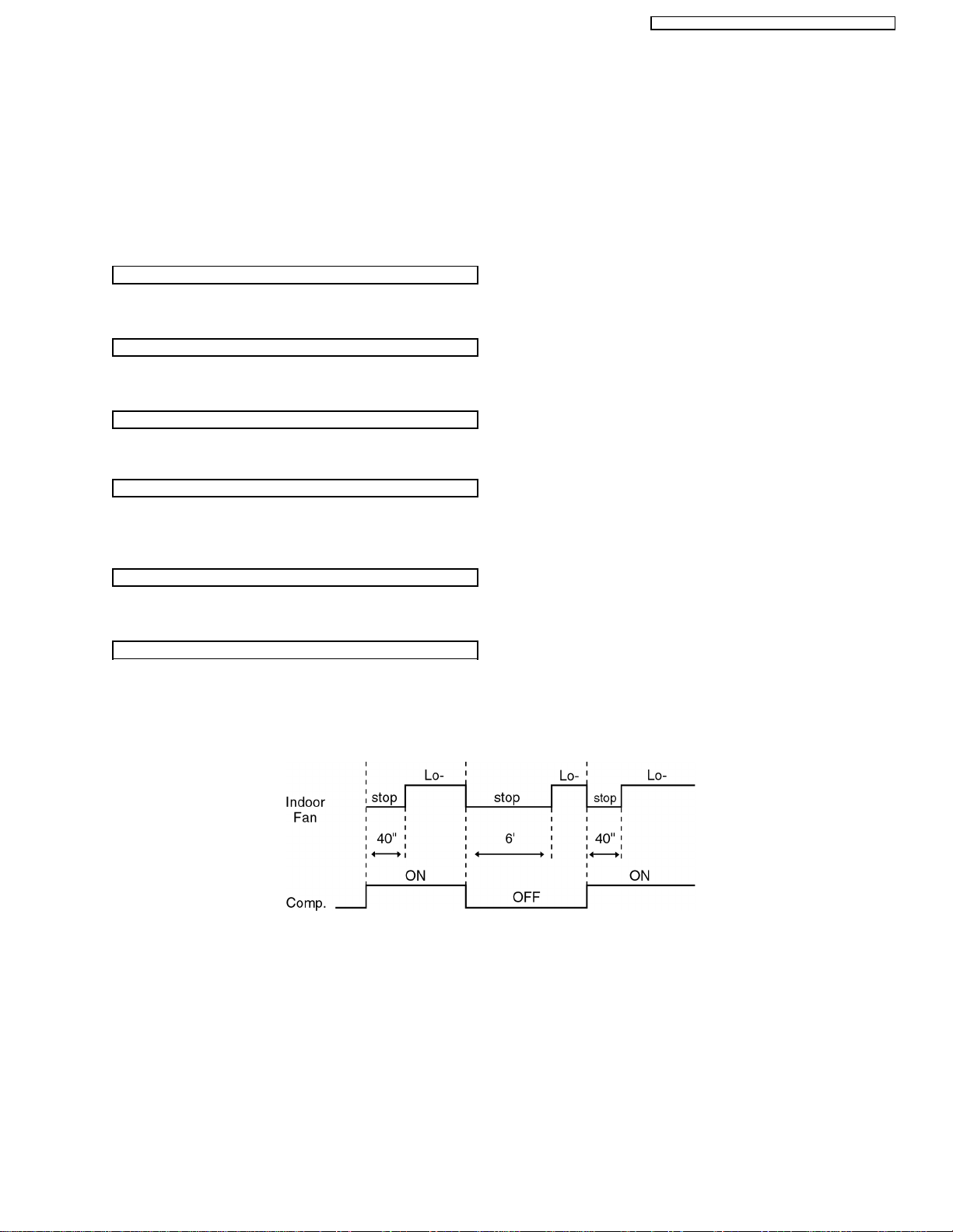
8.2. Soft Dry Mode Operation
The unit starts cooling operation until the room temperature reaches the setting temperature set on the Remote Control, and
•
then Soft Dry operation will start.
During Soft Dry operation, the Indoor Fan will operate at Lo- speed.
•
The operation will be switched on and off for up to 10 minutes “ON” and 6 minutes “OFF”. Once Soft Dry operation is turned
•
off, it stops for 6 minutes.
Time Delay Safety Control
Once the compressor stops, it will not start for 3 minutes during Cooling operation.
•
Starting Current Control
Same as Starting Current Control for Cooling Mode operation.
•
Anti-Freezing Control
Same as Anti-Freezing Control for Cooling Mode operation. (For Soft Dry region, 6 minutes waiting is valid during compressor
•
stops.)
Compressor Reverse Rotation Protection Control
Same as Compressor Reverse Rotation Protection Control for Cooling Mode Operation. (For Soft Dry region, 6 minutes waiting
•
is valid during compressor stops.)
Compressor Protection Control
Same as Compressor Protection Control for Cooling Mode Operation.
•
Automatic Fan Speed Mode
When Automatic Fan Speed is selected at Remote Control during Soft Dry operation.
Fan speed rotates at Lo- speed.
•
Deodorizing Control.
•
19
Page 20
CS-A9CKPG CU-A9CKP6G / CS-A12CKPG CU-A12CKP6G
Soft Dry Operation Time Diagram
Quiet Operation Control
(For Dry region at Soft Dry Mode)
20
Page 21
CS-A9CKPG CU-A9CKP6G / CS-A12CKPG CU-A12CKP6G
8.3. Heating Mode Operation
Heating in operation according to Remote Control setting.
Time Delay Safety Control
When the compressor is stopped by Remote Control, it restarts after 3 minutes when the Remote Control is turned ON.
•
When the setting temperature is reached during heating operation, the compressor stops and it will not start for 4 minutes.
•
30 minutes Time Save Control
The compressor will start automatically if it has stopped for 30 minutes even if the room temperature is between the compressor
•
ON temperature and OFF temperature.
Overload Protection Control
(a) Outdoor Fan Control
If the temperature of the indoor heat exchanger rises to 51°C (123.8°F), Outdoor Fan stops.
•
The Outdoor Fan restarts when the indoor heat exchanger temperature falls to 49°C (120.2°F).
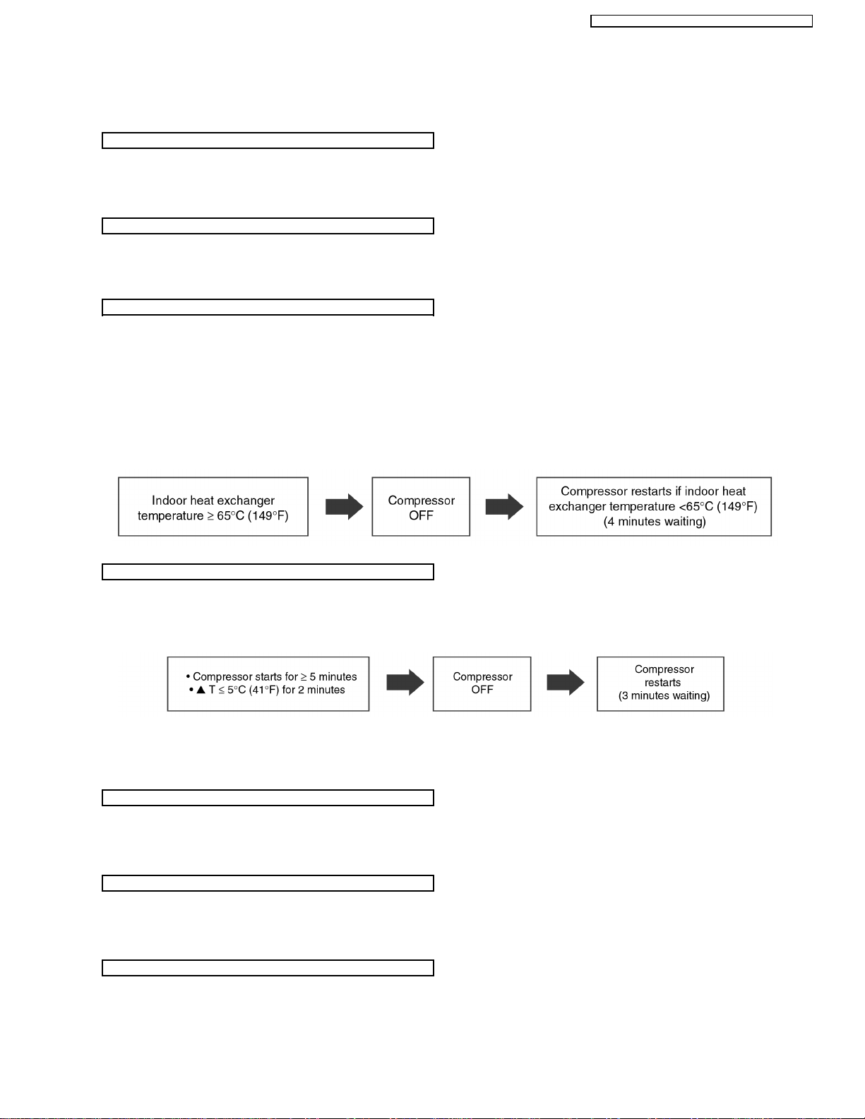
(b) Compressor high pressure protection
If the indoor heat exchanger becomes 65°C (149°F) or more, the compressor will stop and restart automatically.
•
(Time Delay Safety Control - 4 minutes waiting).
Compressor Reverse Rotation Protection Control
If the compressor is operating continuously for 5 minutes or longer and temperature difference between intake air and indoor
•
heat exchanger is 5°C (41°F) or less for 2 minutes, compressor will stop and restart automatically.
(Time Delay Safety Control is valid).
▲
T = Indoor heat exchanger temperature - intake air temperature.
This is to protect reverse rotation of the compressor when there is a instantaneous power failure.
4-way Valve Control
4-way valve always ON during Heating operation. (Except Deicing operation)
•
When the unit is switched to “OFF” during Heating operation, 4-way valve stay at Heating position for 5 minutes.
•
Outdoor Fan Motor Control
When compressor stops (reaches room temperature), outdoor fan will operate for 30 seconds.
•
(30 seconds Forced Operation).
Indoor Fan Motor Control
When compressor stops (reaches room temperature), indoor fan will stop for 1 minutes, operate for 3 minutes, if still not yet
•
reaches the room temperature, indoor fan Lo- for 40 sec. after that operate at SLo speed.
21
Page 22
CS-A9CKPG CU-A9CKP6G / CS-A12CKPG CU-A12CKP6G
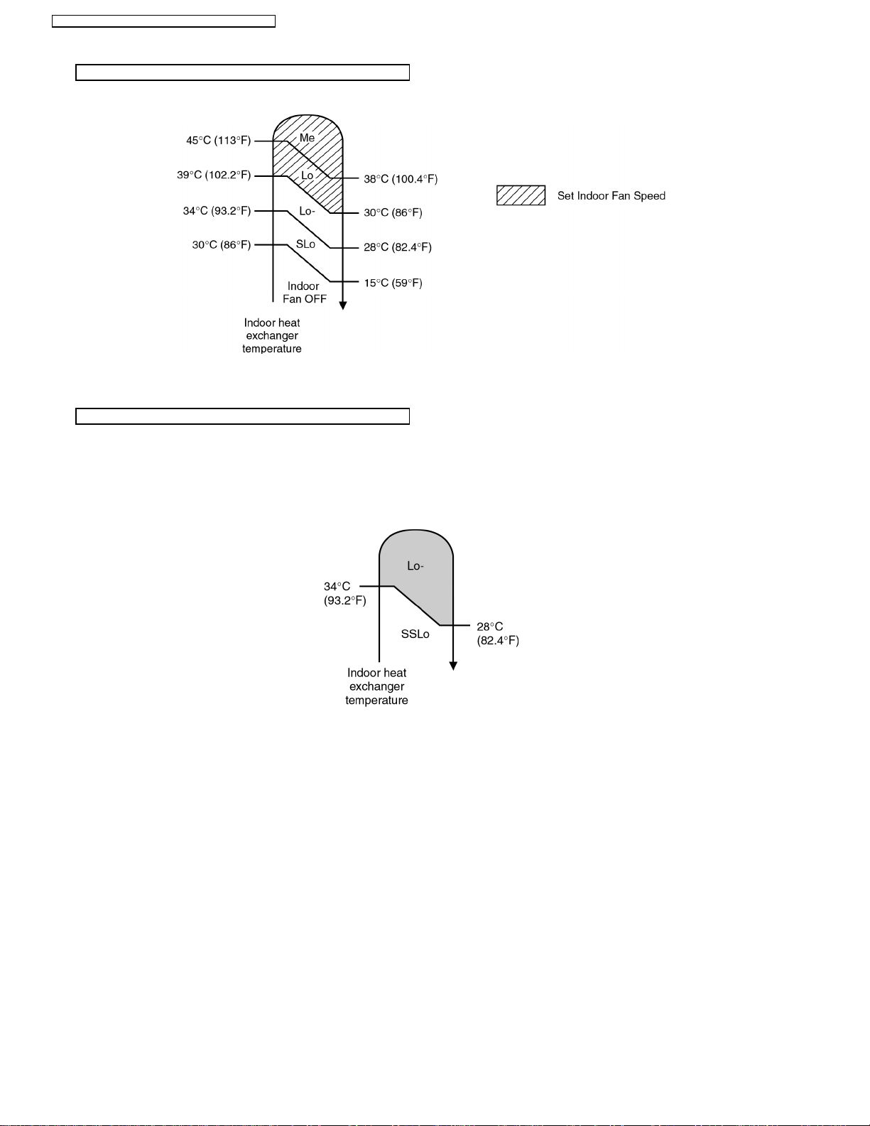
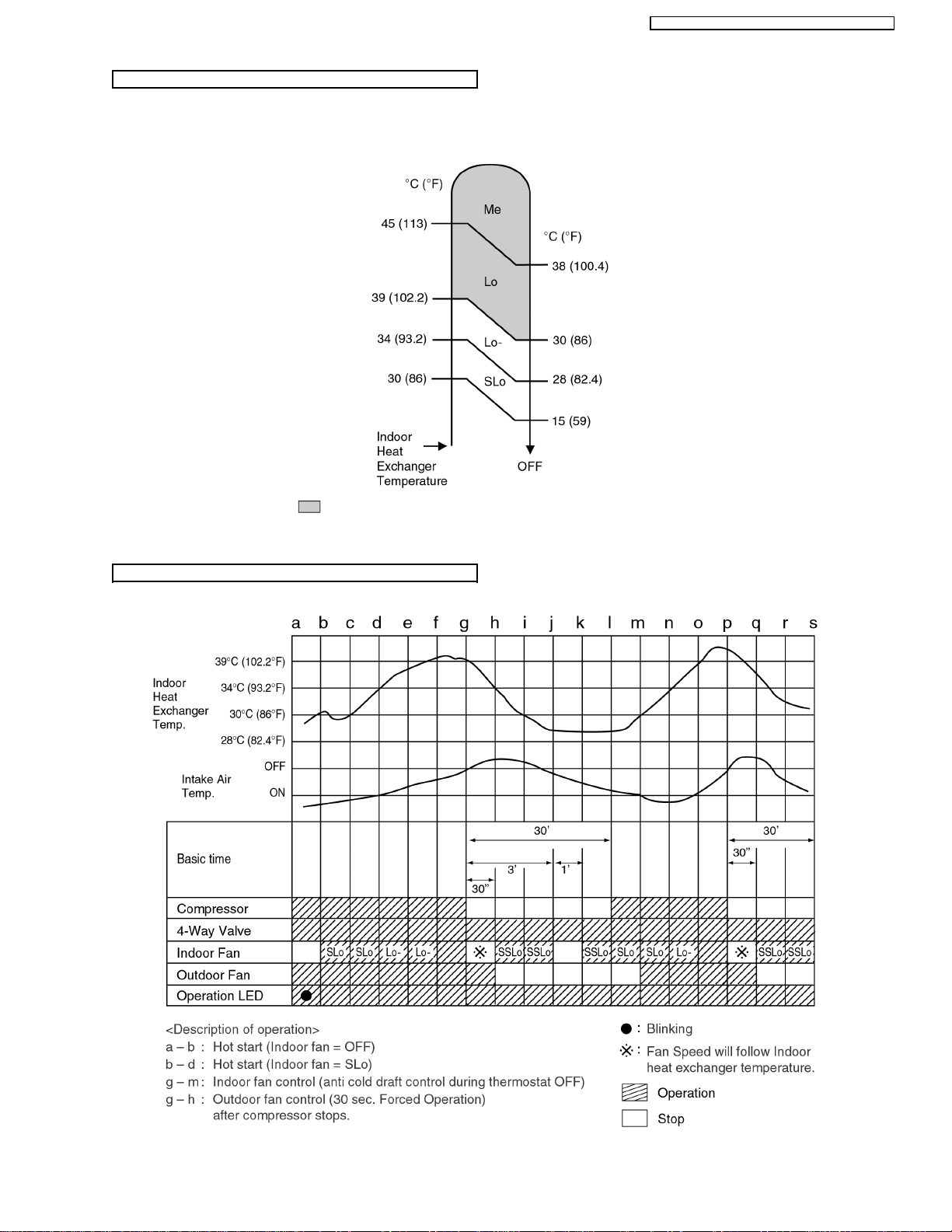
Hot Start Control
When Heating operation starts, Indoor Fan will not start until the indoor heat exchanger reaches 30°C (86°F) as diagram shown.
Hot Start is completed when indoor heat exchanger rises to 39°C (102.2°F) or over 4 minutes.
Anti Cold Draft Control
This operation is to prevent the Cold Draft during Heating mode operation.
•
The operation will start when compressor OFF (Thermo OFF) during Heating operation.
•
For the first 30 sec. from compressor OFF (Thermo OFF), Indoor fan speed will operate accordingly to the Indoor heat
•
exchanger temperature as shown below:
After 30 sec. from compressor OFF (thermo OFF), Indoor fan will run at SSLo speed only.
•
Anti Cold Draft Control will stop when:
•
Intake temperature < set temperature. (Time Delay Safety Control 4 minutes waiting is valid)
−
After 30 minutes time saved control.
−
(refer to next page).
22
Page 23
Automatic Fan Speed Mode
When Automatic Fan Speed is selected at Remote Control during heating operation.
Fan speed rotates in the range of Me→SLo according to the heat exchanger temperature.
•
CS-A9CKPG CU-A9CKP6G / CS-A12CKPG CU-A12CKP6G
If use Manual Fan Speed,
•
Heating Operating Time Diagram
at above diagram will operate with setting Fan Speed.
23
Page 24
CS-A9CKPG CU-A9CKP6G / CS-A12CKPG CU-A12CKP6G
Deicing Control
Deice starts to prevent frosting at outdoor heat exchanger.
Normal Deicing
•
Deice operations detection commences after 30 minutes of Heating operation starts or 60 minutes after previous deice
operation. If the TRS (Thermal Reed Switch) senses the outdoor piping temperature drops to -3°C (26.6°F) (TRS CLOSE)
or less for 50 sec. continuously during compressor is in operation, deice will start.
(There is no detection during Outdoor Fan stops.)
Overload Deicing
•
During heating operation, if the outdoor Fan OFF duration (due to overload control) is accumulated up to 60 minutes and
after compre ssor starts for 1 minutes, deicing starts.
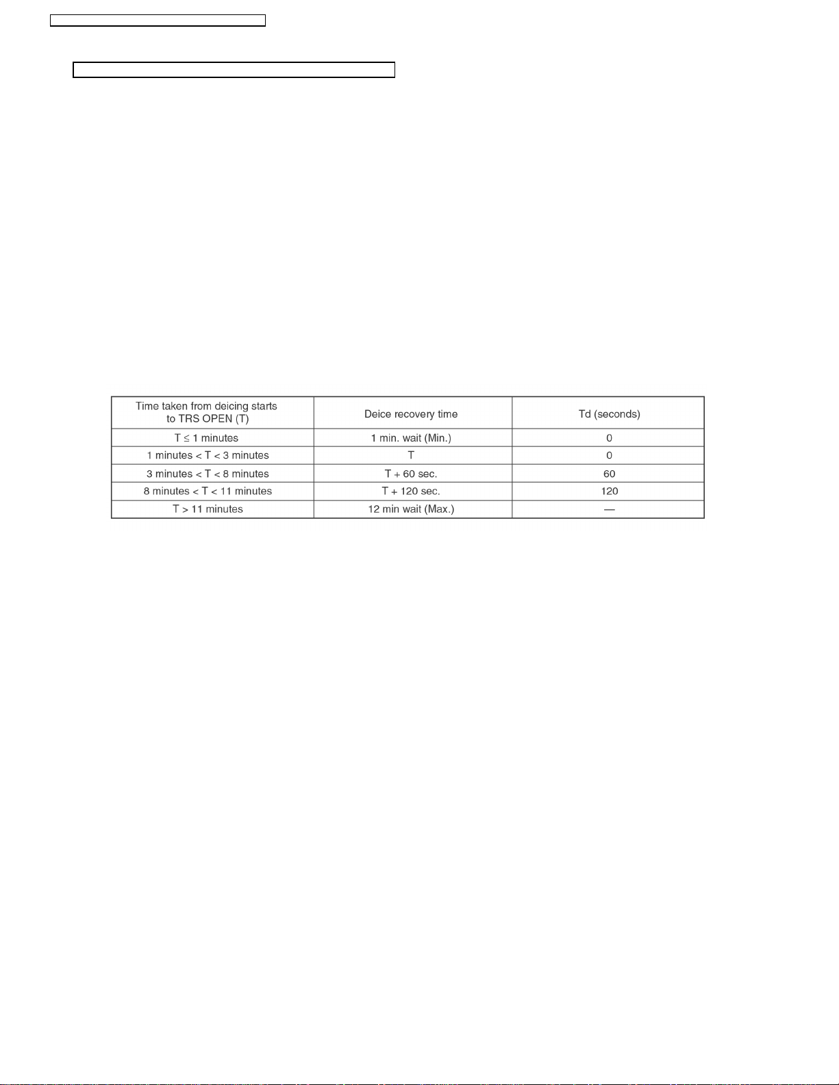
Deicing ends when
•
1. 12 minutes after deicing operation starts;
2. TRS senses the outdoor piping temperature rises to 4°C (39.2°F) (TRS OPEN).
3. Deicing will not end immediately as time delay (Td) is valid as shown below.
Once deicing operation starts, it will not end for 60 seconds.
•
After deicing operation, compressor stops for 30 seconds and 4-way valve stays at cooling position for 10 seconds.
•
24
Page 25
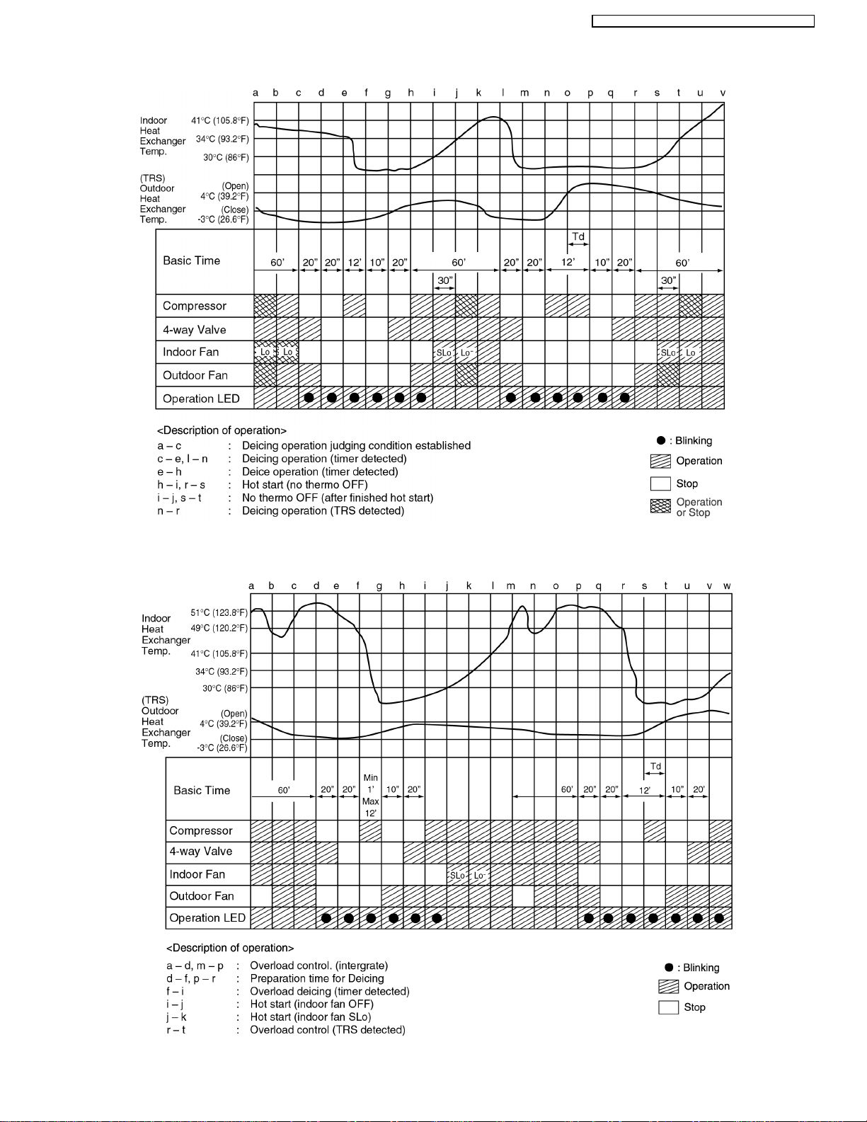
Normal Deicing Time Diagram
CS-A9CKPG CU-A9CKP6G / CS-A12CKPG CU-A12CKP6G
Overload Deicing Time Diagram
25
Page 26

CS-A9CKPG CU-A9CKP6G / CS-A12CKPG CU-A12CKP6G
Quiet Operation Control
(For Heating Mode)
Purpose of this operation is to provide quite heating operation compare to normal operation.
•
When the Quiet Mode is set at the remote control, Quiet Mode LED illuminates, the sound level will be automatically
•
decreased 2 dB (Lo), decreased 3 dB (Hi, Me), against the present sound level operation.
Quiet setting of fan speed rpm refer to Indoor Fan Speed Control.
•
Manual Airflow Direction:-
•
Rpm control during Lo, Me & Hi Cool
−
Auto Airflow Direction:-
•
Rpm control depends on the piping air temperature sensor of Indoor heat exchanger
−
Quiet Mode Operation will stop if:-
•
Quiet mode button is pressed again.
−
Stopped by ON/OFF switch.
−
Timer OFF activates.
−
Powerful mode button is pressed.
−
26
Page 27

CS-A9CKPG CU-A9CKP6G / CS-A12CKPG CU-A12CKP6G
8.4. Automatic Mode Operation
1. When the Automatic Mode Operation is selected, the indoor fan operates at SLo fan speed for 25 seconds to sense intake air
temperature and determine the 1st operation mode.
2. Operation mode will be determine again after 1 hour of operation, if the room temperature reaches to set temperature and
compressor off time is over 7 minutes 30 seconds continuously.
The present operation mode will be continued, if the room temperature does not reach to set temperature (Compressor keeps running)
eventhough after 1 hour from automatic operation mode started.
Present Judgement Next Mode
Mode Cooling Soft Dry Heating
O O
Cooling 23°C Cooling (Judgement: Not Applicable (Judgement:
(73.4°F) Heating 23°C [73.4°F] & Above) Below 23°C [73.4°F])
O O
Soft Dry 20°C Soft Dry Not Applicable (Judgement: (Judgement:
(68°F) Heating 20°C [68°F] & Above) Below 20°C [68°F])
O O
Heating 25°C Cooling (Judgement: Not Applicable (Judgement:
(77°F) Heating Above 25°C [77°F]) 25°C [77°F] & below)
Automatic Set Temperature
Refer 3. as below.
3. Automatic Set Temperature
For each operation, set temperature will automatically set as shown below.
However it can be selected 2°C (35.6°F) higher or 2°C (35.6°F) lower from standard set temperature by pressing the “Room
Temperature Setting button”.
Operation Hi (Standard) Lo
(+2°C [+35.6°F]) (±0°C [±32°F]) (-2°C [-35.6°F])
Cooling 27°C (80.6°F) 25°C (77°F) 23°C (73.4°F)
Soft Dry 24°C (75.2°F) 22°C (71.6°F) 20°C (68°F)
Heating 23°C (73.4°F) 21°C (69.8°F) 19°C (66.2°F)
The mode judging temperature and standard setting temperature can be increased by 2°C (35.6°F), by open the circuit of
•
JX1 at indoor electronic controller.
27
Page 28

CS-A9CKPG CU-A9CKP6G / CS-A12CKPG CU-A12CKP6G
8.5. Random Auto Restart Control
If there is a power failure during air conditioner operation, operation will be automatically restarted after 3 to 4 minutes when the
•
power is resumed. It will start with previous operation mode and airflow direction.
Restart time is decided randomly using 4 parameter:
•
Intake air temperature, setting temperature, fan speed and Air Swing Blade position.
Random Auto Restart Control is not available when Timer is set.
•
This control can be omitted by open the circuit of JX2. (Refer Circuit Diagram)
•
8.6. Delay ON Timer Control
When the Delayed ON Timer is set by using the remote control, the unit will start operate slightly before the set time, so that
•
the room will reach nearly to the set temperature by the desired time.
For Cooling and Soft Dry mode, the operation will start 15 minutes before the set time.
•
For Heating mode, the operation will start 30 minutes before the set time.
•
For Automatic mode, the indoor fan will operate at SLo speed for 25 seconds, 30 minutes before the set time to detect the
•
intake air temperature to determine the operation mode. The operation indication lamp will blink at this time.
8.7. Remote Control Signal Receiving Sound
Long beep sound will be heard when:-
•
Stopping the Air Conditioner using ON/OFF switch.
−
Stopping the Quiet Mode.
−
Stopping the Powerful Mode.
−
Stopping the Economy Mode.
−
Short beep sound will be heard for others.
•
To switch off the beep sound:-
•
Press the “Automatic Operation Button” continuously for 10 seconds or more (“beep” “beep” will be heard at the 10th second).
Repeat the above if you want to switch ON the beep sound.
However, if the “Automatic Operation Button” has been pressed the Automatic operation will be activated.
If you do not require this operation, you may change it by using the remote control.
8.8. Indoor Fan Speed Control
Auto Fan Speed Control
When set to Auto Fan Speed, the fan speed is shifted automatically between Stop to SHi depend on each operation as shown
below.
Manual Fan Speed Control
Basic fan speed adjustment (3 settings, from Lo to Hi) can be carried out by using the Fan Speed selection button at the remote
control.
28
Page 29

CS-A9CKPG CU-A9CKP6G / CS-A12CKPG CU-A12CKP6G
29
Page 30

CS-A9CKPG CU-A9CKP6G / CS-A12CKPG CU-A12CKP6G
8.9. Airflow Direction Control
Vertical Airflow Direction
1.
Cooling, Ion and Soft Dry Mode
The louver swings up and down as shown above.
•
The louver does not swing when the Indoor Fan stops
•
during operation at the upper limit.
Heating Mode
When the intake air temp. reaches 38°C (100.4°F), the
•
louver is changed from upper to lower limit. When the
intake air temp falls to 35°C (95°F), the louver is
changed from lower to upper limit.
The louver can be selected between 14° - 36° (as
•
shown above) when pressing Manual Airflow Direction
Selection Button.
The louver can be selected between 0° - 61° (as shown
•
above) when pressing Manual Airflow Direction
Selection Button.
Horizontal Airflow Direction
2.
The left and right airflow direction louvers can be adjusted manually.
•
30
Page 31

CS-A9CKPG CU-A9CKP6G / CS-A12CKPG CU-A12CKP6G
8.10. Powerful Mode Operation
Purpose of this operation is to be obtain the setting temperature quickly.
Cooling and Soft Dry Mode
1.
When the Powerful Mode is set, the set temperature will be automatically decreased 3°C (37.4°F) against the present
•
setting temperature (Lower temperature: 16°C [60.8°F]). This operation automatically will be running under SHi Fan speed
(cooling), Lo- Fan Speed (Soft Dry).
Vertical Airflow Direction:-
•
In “Manual” setting, the vane will automatically shift down 10° lower than previous setting.
In “Auto” setting, the vane will automatically swing up and down. However the upper and lower limit will be shifted 10°
downward.
Heating Mode
2.
When the Powerful Mode is set, the set temperature will be automatically increased 3°C (37.4°F) against the present setting
•
temperature (Highe r temperature: 30°C [86°F]).
The Fan Speed will shift as shown below:
•
Vertical Airflow Direction:-
•
In “Manual” setting, the vane will automatically shift down 5° lower than previous setting.
In “Auto” setting, the vane will automatically shift between upper and lower limit depending on the intake air temperature as
Heating Mode, Airflow Direction Auto-Control. However the upper and lower limit will be shifted 5° downward.
Powerful mode will operate for 15 minutes only.
3.
Powerful Mode will stop if:
4.
Powerful mode button is pressed again.
•
Stopped by ON / OFF switch.
•
Timer-off activates.
•
Quiet mode button is pressed.
•
Operating mode is changed.
•
31
Page 32

CS-A9CKPG CU-A9CKP6G / CS-A12CKPG CU-A12CKP6G
8.11. Economy Mode Operation
Purpose of this operation is to save or reduced electrical power consumption of the room air conditioner.
However consumer is advised to use Economy Mode operation after the room temperature reaches the desired temperature.
Cooling and Soft Dry Mode
1.
When the Economy Mode is set, the set temperature will be automatically increased 0.5°C (32.9°F) against the present
•
setting temperature. This operation automatically will be running under Lo- Fan speed.
Vertical Airflow Direction:-
•
In “Manual” or “Auto” setting, the vane will automatically change to Auto Air Swing.
Heating Mode
2.
When the Economy Mode is set, the temperature will be automatically decreased 0.5°C (32.9°F) against the present setting
•
temperature.
The Fan Speed will shift as shown below:
•
Vertical Airflow Direction:-
•
In “Manual” or “Auto” setting, the vane will automatically change to Auto Air Swing.
Economy Mode will stop if:
3.
Economy mode button is pressed again.
•
Stopped by ON / OFF switch.
•
Timer-off activates.
•
Powerful mode button is pressed.
•
Fan Speed control button is pressed.
•
Quiet mode button is pressed ON.
•
Operating mode is changed.
•
Air Swing condition is changed.
•
32
Page 33

CS-A9CKPG CU-A9CKP6G / CS-A12CKPG CU-A12CKP6G
8.12. Low outdoor ambient temperature control
A. Purpose
To protect air conditioner from damage under the low outdoor ambient temperature.
(Low outdoor ambient temperature < -10°C [14°F]).
B. During low outdoor ambient temperature control activated, other compressor & outdoor fan motor control is ignored. (Apply
to all operation modes.)
C. Basic operation
1. Protection control
Outdoor unit stop operation regardless operation mode setting.
33
Page 34

CS-A9CKPG CU-A9CKP6G / CS-A12CKPG CU-A12CKP6G
Note:
# : Fan motor off condition depends on:
a. 1 min over after FM ON. And
b. Air temperature < -3°C (26.6°F) during 1 min.
So the FM Off time is between 5 sec. to 1 min. 5 sec.
D. Indoor condition during protection control
Operation mode I/D FM Protection control;
Cooling Setting speed Compressor reverse
Soft dry Cooling zone Setting speed Compressor reverse
Soft dry zone SLo Compressor reverse
Heating Speed depends on I/D
piping temperature
Automatic Depends on mode judgement.
#1: I/D fan speed and protection control depends on the operation mode. Then, the condition follow operation mode in table above.
rotation protection
rotation protection
rotation protection
Nil
#1
34
Page 35

9 Operating Instructions (U.S.A. Models)
AUT
AUT
HEA
T
DR
AN
COOL
AN
AUT
CS-A9CKPG CU-A9CKP6G / CS-A12CKPG CU-A12CKP6G
SAFETY PRECAUTIONS
Before operating, please read the following
“Safety Precautions” carefully.
● To prevent personal injury, injury to others and
property damage, the following instructions must be
followed.
● Incorrect operation due to failure to follow instructions
will cause harm or damage, the seriousness of which
is classified as follow:
! Warning
This sign warns of death or serious injury.
! Caution
This sign warns of damage to property.
● The instructions to be followed are classified by the
following symbols:
This symbol (with a white background) denotes an
action that is PROHIBITED.
F
F
O
These symbols (with a black background) denote
actions that are COMPULSORY.
■ Installation Precautions
! Warning
● Do not install, remove and reinstall the unit by
yourself.
Improper installation will cause leakage, electric
shock or fire. Please engage an authorized dealer
or specialist for the installation work.
! Caution
● This room air conditioner must be
earthed.
Improper grounding could cause
electric shock.
● Ensure that the drainage piping is
connected properly.
Otherwise, water will leak out.
● Do not install the unit in a
potentially explosive atmosphere.
Gas leak near the unit could cause
fire.
■ Operation Precautions
! Warning
This sign warns of death or serious injury.
● Do not operate with wet hands.
● Do not insert finger or other objects into the
indoor or outdoor units.
● Do not expose directly to cold air for a long
period of time.
● Use specified power cord.
● If abnormal condition (burnt smell, etc.)
F
F
O
occurs, switch off the power supply.
! Caution
This sign warns of injury.
● Do not wash the unit with water.
● Do not use for other purposes such as
preservation.
● Do not use any combustible equipment at
airflow direction.
● Do not sit or place anything on the outdoor
unit.
● Switch off the power supply before cleaning.
● Ventilate the room regularly.
● Pay attention as to whether the installation
rack is damaged after a long period of usage.
● Switch off the power supply if the unit is not
F
F
O
used for a long period.
NAME OF EACH PART
■ Indoor Unit
1
2
R
R
E
E
M
M
I
I
R
R
T
T
E
E
M
IM
I
T
T
T
T
E
E
I
I
U
U
T
T
Q
Q
E
E
I
I
U
U
Q
Q
R
R
E
E
W
W
R
R
O
O
E
E
P
P
W
W
O
O
P
P
L
L
U
U
F
F
L
L
R
R
U
U
E
E
F
F
W
W
R
R
O
O
E
E
P
P
W
W
O
O
P
P
Y
Y
M
M
O
O
Y
Y
N
N
M
M
O
O
O
O
C
C
N
N
E
E
O
O
C
C
E
E
6
1 Front Panel
2 Air Intake Vent
3 Air Outlet Vent
4 Vertical Airflow Direction Louver
5 Horizontal Airflow Direction Louver
(manually adjusted)
6 Indicator Panel
123 654
ECONOMYECONOMY POWERPOWER
ECONOMYECONOMY
1 Auto Operation Button
(when the front panel is opened)
2 Economy Mode Indicator – GREEN
3 Powerful Mode Indicator – ORANGE
4 Power Indicator – GREEN
5 Quiet Mode Indicator – ORANGE
6 Timer Mode Indicator – ORANGE
345
POWERFULPOWERFUL
POWERFULPOWERFUL
QUIETQUIET
TIMERTIMER
QUIETQUIET
POWERPOWER
TIMERTIMER
● Indoor Unit
(when the front panel is opened)
1
3
2
1 Front Panel
2 Air Filters
3 Air Purifying Filter
■ Outdoor Unit
1
6
1 Air Intake Vents
2 Ground Terminal
(Inside cover)
3 Piping
4 Conduit
5 Drain Hose
6 Air Outlet Vents
■ Accessories
● Remote Control
A
U
T
O
H
E
A
T
C
O
O
N
O
L
A
O
U
F
D
F
T
R
F
O
YFAN
A
U
Q
FA
T
T
U
O
E
N
I
M
E
T
P
M
O
D
E
OF
AI
E
F
R
C
/
S
O
O
S
t
N
W
N
e
O
p
I
M
N
Y
G
1
O
N
S
L
E
E
O
P
2
F
F
F
A
N
S
P
E
E
D
C
3
H
E
T
C
S
IM
K
E
R
E
T
E
R
S
E
T
C
A
C
N
L
O
C
C
E
K
L
+
B
A
T
T
E
R
Y
● Remote Control Holder
● Two RO3 (AAA) dry-cell batteries or equivalent
2
3
4
5
● Air Purifying Filter
(Air Purifying Filter)
(Solar Refreshing Deodorizing Filter)
35
Page 36

AUTO
O
F
AUTOHEAT
DRY
FANCOOL
FAN
AUTO
AUTO
S
L
E
CHECK
TEMP
AUTAUTO
ON
OFF
AUTAUTOHEAHEAT
DRYFAN
F
COOLCOOL
FANAN
AUTAUTO
RESET CLOCK
MODE
POWERFUL
ECONOMY
FAN SPEED
AIR SWING
OFF
CANCEL
ON
SET
1
2
3
TIMER
OFF/ON
QUIET
AUTO
MANUAL
#
!
$
%
^
$
*
&
3
5
8
7
9
0
6
4
(
CHECK
AUTO
AUTO HEAT DRY FANCOOL
FAN
AUTO
RESET CLOCK
FAN SPEED
AIR SWING
OFF
CANCEL
ON
SET
1
2
3
TIMER
AUTO
MANUAL
1
2
O
F
F
O
N
H
E
A
HEAT
DRDRY
FA
N
ANC
O
O
L
COOL
C
H
E
C
K
T
E
M
P
A
U
T
AUTO
A
U
T
AUT
O
FA
N
AN
AUTAUTO
R
E
S
E
T
C
L
O
C
K
A
IR
S
W
IN
G
OFF
C
A
N
C
E
L
1
2
3
T
I
M
ER
O
F
F
/
O
N
Q
U
I
E
T
A
U
T
O
M
A
N
U
A
L
E
C
O
N
O
M
Y
POWERFUL
ON
S
E
T
FAN SPEED
M
O
D
E
CS-A9CKPG CU-A9CKP6G / CS-A12CKPG CU-A12CKP6G
NAME OF EACH PART
■ Remote Control
1
2
● Remote Control Signal
• Make sure it is not obstructed.
• Maximum distance : 10 m (32.8 ft.).
• Signal received sound :
One short beep or one long beep.
● Notes for Remote Control
• Do not throw or drop.
• Do not get it wet.
• Certain types of fluorescent lamps may affect
signal reception. Consult your dealer.
1 Signal Transmitter
2 Operation Display
3 Quiet Mode Operation Button
4 Room Temperature Setting Button
(Illuminating button)
5 Operation Mode Selection Button
6 Economy Mode Operation Button
7 Auto Airflow Direction Button
8 ON-Timer Button
9 OFF-Timer Button
0 Reset Point
(Press with fine-tipped object to clear the memory)
! OFF/ON Button
(Illuminating button)
@ Powerful Mode Operation Button
# Fan Speed Selection Button
$ Manual Airflow Direction Selection Button
% Timer Set Button
^ Timer Cancellation Button
& Time-Setting Button
* Clock Button
( Remote Control Cover
● How to Insert the Batteries
2
1.5V
P
O
W
E
R
F
U
M
O
D
E
A
A
E
I
R
U
C
O
T
S
N
O
W
O
I
M
N
G
1
M
O
A
N
N
U
A
L
O
2
F
F
F
A
C
H
E
C
1.5V
N
3
T
S
IM
K
ET
R
E
E
R
S
E
T
C
A
C
N
L
O
C
C
E
K
L
1
1
Slide down the remote control cover completely
to remove it.
2
Insert the batteries
– Be sure the direction is correct
– 12:00 on display - flashing
• Set the current time (CLOCK) immediately to
prevent battery exhaustion.
3
Re-install the remote control cover by inserting it
in the side groves and pushing inward.
● About the batteries
• Can be used for approximately one year.
● Observe the following when replacing the
batteries
• Replace with new batteries of the same type.
• Do not use rechargeable batteries (Ni-Cd).
• Remove the batteries if the unit is not going to be
used for a long period.
L
Y
S
P
E
E
D
PREPARATION BEFORE OPERATION
HOW TO OPERATE
■ Indoor Unit
1
5
2
4
3
1
Open the front panel
2
Remove the air filters
3
Fit the air purifying filters in place
4
Insert the air filters
5
Close the front panel
■ Remote Control – To set the current time
1
Press 1.
2
Then press 2 to increase or decrease the time.
3
Press 1 again.
Set time on display will light up.
■ To start the operation
■ Setting Mode
2
3
5
• Press 1.
• POWER indicator (green) on the indoor unit will light
up.
• To stop, press once more.
1
6
4
• Press 2 to select:-
Cooling Model
AUTO – Automatic Operation
COOL – Cooling Operation
DRY – Soft Dry Operation
FAN – Air Circulation Operation
Heat Pump Model
AUTO – Automatic Operation
HEAT – Heating Operation
COOL – Cooling Operation
DRY – Soft Dry Operation
36
■ Setting Temperature
• Press 3 to increase or decrease the temperature.
• The temperature can be set between 60°F ~ 86°F.
• Recommended temperature:
Cooling Model
COOL –> 75°F ~ 78°F
DRY –> 2°F ~ 4°F
lower than the
room temperature
Heat Pump Model
COOL –> 75°F ~ 78°F
DRY –> 2°F ~ 4°F
lower than the
room temperature
HEAT –> 68°F ~ 75°F
• During AUTO Operation, press 3 to select:-
• Operation with 4°F higher than the standard
temperature.
• Operation with the standard temperature.
• Operation with 4°F lower than the standard
temperature.
● Standard Temperature
Cooling Model
Indoor
temperature
• Once the Automatic Operation is selected, the indoor
temperature sensor operates automatically to select
the desired operation mode with Cooling or Soft Dry.
• After the operation mode has been selected, the
mode does not change.
Indoor
temperature
• At the beginning of the automatic operation, Heating,
Cooling or Soft Dry is automatically selected according
to the indoor temperature.
• The operation mode changes every hour, when
necessary.
73°F
73°F
68°F
Operation
Cooling
Soft Dry
Heat Pump Model
Operation
Cooling
Soft Dry
Heating
Standard
temperature
77°F
72°F
Standard
temperature
77°F
72°F
70°F
Page 37

AUTO
AUTOHEAT DRY FANCOOL
FAN
AUTO
MODE
POWERFUL
ECONOMY
FAN SPEED
AIR SWING
OFF
CANCEL
ON
SET
1
2
3
TIMER
OFF/ON
QUIET
AUTO
MANUAL
3
6
4
1
7
5
2
CS-A9CKPG CU-A9CKP6G / CS-A12CKPG CU-A12CKP6G
■ Setting the Fan Speed
• Press 4 to select:FAN – Low Fan Speed
FAN – Medium Fan Speed
FAN – High Fan Speed
AUTO
FAN – Automatic Fan Speed
The speed of the indoor fan is adjusted
automatically according to the operation.
The indoor fan stops occasionally during
cooling operation.
■ Setting the Vertical Airflow Direction
• Press 5 or 6 to select:-
Cooling Model
COOL / DRY Operation
AUTO
FAN Operation
AUTO
36° 61°
Swing up/down
Automatically
MANUAL
Five stages of adjustment
can be made between
14 ~ 36 angle.
Move up/down
Automatically
MANUAL
Five stages of adjustment
can be made between
0 ~ 61 angle.
Heat Pump Model
COOL / DRY Operation
AUTO
36°
Swing up/down
Automatically
MANUAL
Five stages of adjustment
can be made between
14 ~ 36 angle.
HEAT Operation
AUTO
– When the discharge air
temperature is low such
as at the start of heating
operation, the air blows
in a horizontal direction.
As the temperature
rises, the hot air blows
in a downward direction.
– To stop this operation,
press MANUAL.
MANUAL
Five stages of adjustment
can be made between
0 ~ 61 angle.
■ Setting the Horizontal Airflow Direction
R
R
E
E
M
M
I
I
R
R
T
T
E
E
M
M
I
I
T
T
T
T
E
E
I
I
U
U
T
T
Q
Q
E
E
I
I
U
U
Q
Q
R
R
E
E
W
W
R
R
O
O
E
E
P
P
W
W
O
O
P
P
L
L
U
U
F
F
L
L
R
R
U
U
E
E
F
F
W
W
R
R
O
O
E
E
P
P
W
W
O
O
P
P
Y
Y
M
M
O
O
Y
Y
N
N
M
M
O
O
O
O
C
C
N
N
E
E
O
O
C
C
E
E
• Adjust it manually
● Use this air conditioner under the following
conditions:
Cooling Model
(Unit in °F)
DBT: Dry Bulb Temp
WBT: Wet Bulb Temp
Maximum Temperature
Minimum Temperature
Indoor Outdoor
WBT
DBT
DBT
73.4
109.4
89.6
51.8
60.8
60.8
WBT
78.8
51.8
Heat Pump Model
(Unit in °F)
DBT: Dry Bulb Temp
WBT: Wet Bulb Temp
Maximum Temperature-Cooling
(Maximum Temperature-Heating)
Minimum Temperature-Cooling
(Minimum Temperature-Heating)
● Notes
• If the unit is not going to be used for an extended
period of time, turn off the main power supply. If it is
left at the ON position, approximately 2.5 W of
electricity will be used even if the indoor unit has been
turned off with the remote control.
• If operation is stopped, then restart immediately, the
unit will resume operation only after 3 minutes.
Indoor Outdoor
DBT
WBT
DBT
89.6
73.4
109.4
(86)
(–)
(75.2)
60.8
51.8
60.8
(60.8)
(–)
(23)
WBT
78.8
(64.4)
51.8
(21.2)
● Operation Details
COOL – Cooling Operation
• To set the room temperature at your preference
cooling comfort.
AUTO – Automatic Operation
• Sense indoor temperature to select the optimum
mode.
• Temperature is not displayed on the remote control
during AUTO operation.
DRY – Soft Dry Operation
• A very gentle Cooling Operation, prior to
dehumidification. It does not lower the room
temperature.
• During Soft Dry operation, the indoor fan operates at
Low fan speed.
HEAT – Heating Operation
(for Heat Pump Model only)
• Heat is obtained from outdoor air to warm up the
room. When the outdoor ambient air temperature
falls, the heating capacity of the unit might be
reduced.
• Defrosting Operation
Depending on the outdoor temperature, the operation
occasionally stops to melt the frost on the outdoor
unit.
FAN – Air Circulation Operation
(for Cooling Model only)
• When the room temperature reaches the set
temperature, operation commences at Low airflow
volume. It stops when the room temperature drops to
4°F below the set temperature.
(It is useful when using a heater).
• Hi fan speed will not operate when using the air
circulation Fan mode.
8
SETTING THE TIMER
Ensure that the current time is correct before setting
the timer. The timer cannot be set if the time display
is flashing.
■ ON-TIMER Operation
To start the air conditioner operation automatically.
• Press 1 to set the operation.
• Press 2 to increase or decrease the time.
• Then press 3.
• To cancel this operation, press 4.
■ OFF-TIMER Operation
To stop the air conditioner operation automatically.
• Press 5 to set the operation.
• Press 2 to increase or decrease the time.
• Then press 3.
• To cancel this operation, press 4.
● Timer Mode Operation Details
• When the ON-Timer is set, operation will start
before the actual set time. This is to enable the
room temperature reaches the set temperature at
the set time.
Cooling Model
COOL,DRY, –> 15 minutes
AUTO in advance
• Once the ON/OFF Timer is set, operation will
start/stop at the set time everyday.
• The current time is not displayed when the timers
are set.
• When both timers are used together, the TIMER
mode indicator on the indoor unit remains lit even
when the operation is stopped by the OFF-TIMER.
Heat Pump Model
COOL,DRY, –> 15 minutes
HEAT, AUTO–>30 minutes
in advance
in advance
CONVENIENCE OPERATION
■ Powerful Mode Operation
To obtain the set temperature quickly.
• Press 6.
* Powerful mode indicator (orange) on the indoor
unit will light up.
* Powerful mode will operate for 15 minutes only.
• To cancel this operation, press once more.
■ Economy Mode Operation
To save electrical power consumption.
Please use this mode when the room has reached
your desired temperature.
• Press 7.
* Economy mode indicator (green) on the indoor unit
will light up.
• Press once more to cancel this operation.
●
Economy/Powerful Mode Operation Details
• Economy and Powerful operation cannot be
selected simultaneously.
• The changes of the temperature and airflow volume
are automatic.
• The remote control display remains unchanged.
• If operation mode button is pressed, economy or
powerful operation will be cancelled.
• During FAN – Air circulation operation, the powerful
and economy operation are not available.
(for Cooling Model only)
Economy Mode
Operation
COOL / DRY
HEAT
(for Heat Pump
model only)
Powerful Mode
Operation
COOL / DRY
HEAT
(for Heat Pump
model only)
Temperature
1°F higher
than set temp.
1°F lower
than set temp.
Temperature
5°F lower
than set temp.
5°F higher
than set temp.
Airflow
volume
Super Low
Automatic
Airflow
volume
Super High
Automatic
■ Quiet Mode Operation
To provide quiet operation.
• Press 8.
Quiet mode indicator on the indoor unit will light up.
*
• To cancel this operation, press once more.
●
Operation Details
• Air flow sound will reduce during operation.
37
Page 38

CS-A9CKPG CU-A9CKP6G / CS-A12CKPG CU-A12CKP6G
CARE AND MAINTENANCE
■ Cleaning the Indoor Unit and Remote
Control
• Wipe gently with a soft, dry cloth.
• Do not use water hotter than 104˚F or polishing fluid
to clean the unit.
■ Cleaning the Air Filter
(Recommendation:- If the unit is operated in a dusty
environment, clean the filters every two weeks.
Continuous use of this dirty filters will reduce cooling
or heating efficiency)
1
Remove dirt using a vacuum cleaner.
2
Wash back of the air filter with water.
3
If badly soiled, wash it with soap or a mild household
detergent.
4
Let it dry and reinstall it.
Be sure the “FRONT” mark is facing you.
* Damaged air filter.
Consult the nearest authorized dealer.
Part No.: CWD001098.
• Do not use benzene, thinner, scouring powder or
clothes soaked in caustic chemical to clean the unit.
■ Cleaning the Front Panel
(Must be removed before washing)
1
Raise the front panel higher than the horizontal and
pull to remove it.
2
Gently wash with water and a sponge.
• Do not press the front panel too hard when washing.
• When use kitchen cleaning fluid (neutral detergent),
rinse throughly.
• Do not dry the front panel under direct sunlight.
3
To affix the front panel, raise the front panel
horizontally, match the protruding portion on the
indoor unit to the fulcrum and push into place.
Fulcrum
Protruding portion on indoor unit
■ Air Purifying Filters
1
Raise the
front panel
Solar Refreshing
Deodorizing Filter
Air Purifying Filter
Remove the air filters
2
● Solar Refreshing Deodorizing Filter
• Used to remove unpleasant odor and deodorize
the air in the room.
• Reusable.
• Vacuum, place under direct sunlight for 6 hours and
fit it back in place.
(Recommended: every 6 months)
• Recommended to change this filter every 3 years.
● Air Purifying Filter
• This new filter helps trap small airborne particles
such as dust, pollen and tobacco smoke.
• Recommended : change this filter every 3 months.
• Do not reuse damaged filters.
Consult the nearest authorized dealer to purchase a
new filter.
Air Purifying Filter No.: CZ-SF51P
Solar Refreshing Deodorizing Filter No.: CZ-SFD70P
• If you operate the air conditioner with dirty filters:– Air is not purified
– Cooling or heating capacity decreases
– Foul odor is emitted
■ Pre-season Inspection
● Is the discharged air cold/warm?
Operation is normal if 15 minutes after the start of
operation, the difference between the air intake and
outlet vents temperature is:-
Cooling Model
COOL –> 14°F or above
Heat Pump Model
COOL –> 14°F or above
● Are the air intake or outlet vents of the indoor or
● Are the remote control batteries weak?
■ When the Air Conditioner is Not Used
■ Recommended Inspection
HEAT –> 25°F or above
outdoor units obstructed?
If the remote control display appears weak, replace
the batteries.
for an Extended Period of Time
1
To dry the internal parts of the indoor unit, operate
the unit for 2 - 3 hours using:-
Cooling Model
FAN operation
Heat Pump Model
COOL operation with 86°F
set temperature
2
Stop the operation by remote control and switch off
the circuit breaker.
Note : If the unit is not switched off by the remote
control, it will start operating when the circuit
breaker is switched to ON. (The unit is equipped
with Auto Restart Control.)
3
Remove the remote control batteries.
• After used over several seasons, the unit will
become dirty and thus decreases the unit’s
performance. Depending on the operation
conditions, a dirty unit may produce odor and dust
may pollute dehumidification system. Therefore, a
seasonal inspection is recommended in addition to
regular cleaning. (Consult an authorized dealer.)
HELPFUL INFORMATION
■ Auto Operation Button
POWERFULPOWERFUL
ECONOMYECONOMY POWERPOWER
ECONOMYECONOMY
•
Raise the front panel and press.
● Automatic Operation
• If the remote control fails to function or has been
misplaced, press the Auto Operation button to start
the Automatic operation.
• The Automatic operation will be activated
immediately once the Auto operation button is
pressed. However, temperature cannot be adjusted
when in this mode.
• The power indicator on the indoor unit will blink until
the operation mode is selected automatically.
• To cancel this operation, press once more.
● Remote Control Signal Receiving Sound
• To switch off the beep (Signal Receiving Sound),
press the Auto Operation button for 10 seconds
continuously or longer.
A “beep”, “beep” sound will be heard at the
tenth seconds.
Note : A “beep” sound will be heard at the fifth
seconds;
However please press continuously until you
heard “beep”, “beep” sound.
• Repeat the above steps if you want to switch on the
Signal Receiving Sound.
● (This is for Servicing purposes only.)
Note: If you press this button continuously for 5 to 10
seconds, Test Run operation will be performed. A
“beep” sound will be heard after five seconds
indicating the Test Run starts to operate.
QUIETQUIET
TIMERTIMER
POWERPOWER
QUIETQUIETPOWERFULPOWERFUL
TIMERTIMER
■ Auto Restart Control
• If power is resumed after a power failure, the
operation will restart automatically after 3 - 4
minutes.
• Operation will be restarted automatically under the
previous operation mode and airflow direction when
power is resumed as the operation is not stopped
by the remote control.
■ Timer Setting
• When power failure occurs, the timer setting will be
cancelled. Once power is resumed, reset the timer.
■ Thunder and Lightning
• This air conditioner is equipped with a built-in surge
protective device. However, in order to further
protect your air conditioner from being damaged by
abnormally strong lightning activity, you may switch
off the circuit breaker.
ENERGY SAVING AND OPERATION
HINTS
■ Setting the Temperature
• Approximately 10% of electricity can be saved.
• Set the temperature higher or lower than the
desired temperature.
Cooling Model
Cooling Operation : 2°F higher
Heat Pump Model
Cooling Operation : 2°F higher
Heating Operation : 4°F lower
■ Air Filters
• Clean the air filters every 2 weeks.
• Dirty filters may reduces cooling or heating
efficiency.
■ Keep All Doors and Windows Closed
• Otherwise, cooling or heating performance will be
reduced and electricity cost is wasted.
■ Outdoor Unit
• Do not block the air outlet vents. Otherwise, it will
lower the cooling or heating performance.
■ Timer
• To prevent wastage of electricity, use Timer when
going out.
■ Avoid Direct Sunlight
• Keep curtains or drapes closed to avoid direct
sunlight during cooling operation.
38
Page 39

TROUBLESHOOTING
■ Normal Operation
• Air conditioner has been restarted, but does not
operate for 3 minutes.
• A sound like water flowing can be heard.
• It seems that fog is coming out from the air
conditioner.
• The room has a peculiar odor.
• During Automatic Vertical Airflow setting,
indoor fan stops occasionally.
• The outdoor unit emits water or steam.
• (For Heat Pump Model only)
Operation stops for about 12 minutes during
heating (The power indicator blinks.)
• (For Heat Pump Model only)
During heating operation, indoor fan may
run at on and off conditions.
■ Abnormal Operation
Check the following points before calling for repairs or service. If the malfunction persists, please contact your nearest
servicenter. For assistance, please call: (866)-292-7292, for Hawaii residents call (808)-488-7779.
Symptoms?
• The air conditioner does not operate.
• Air conditioner produces loud noise during
operation.
• The air conditioner does not cool or warm
effectively.
• Remote control / display doesn’t work.
• This is to protect the air conditioner. Wait until the air
conditioner begins to operate.
• This is the sound of refrigerant flowing inside the air
conditioner.
• Condensation occurs when the airflow from the air
conditioner cools the room.
• This may be a damp smell emitted by the wall,
carpet, furniture or clothing in the room.
• This is to remove smell emitted by the surroundings.
• In COOL/DRY operation, moisture in the air
condenses into water on the cool surface of outdoor
unit piping that causes dripping.
• This is to melt the frost which has accumulated on
the outdoor unit (defrosting operating). This will take
no longer than about 12 minutes. Water drips from
the outdoor unit. Wait until this operation ends. (The
power indicator will light up.)
(Frost accumulates on the outdoor unit when the
outdoor temperature is low and humidity is high.)
• This is to prevent undesired cooling effect during
heating operation.
Please check
• Has the circuit breaker been tripped?
• Is the timer being used correctly?
• Is the installation work slanted?
• Is the front grille closed properly?
• Has the temperature been set incorrectly?
• Are the filters dirty?
• Are the intake or outlet vents of the outdoor unit
obstructed?
• Are all windows and doors closed?
• Batteries not inserted?
• Batteries correctly inserted (+) and (–)?
Is it okay?
Solution
CS-A9CKPG CU-A9CKP6G / CS-A12CKPG CU-A12CKP6G
■ Call the Dealer Immediately
If the following conditions occur, turn off the circuit
breaker, and then call your authorized Panasonic dealers
or servicenter.
• Abnormal noise is heard during operation.
• Water or foreign material gets into the remote
control by mistake.
• Water leak from the indoor unit.
• Switches or buttons do not operate properly.
• The circuit breaker switches off frequently.
• Power supply cord becomes unusually warm.
Service information can be obtained by calling
(866)-292-7292, for Hawaii residents call (808)-488-7779.
To expedite the repair of your air conditioner:
• Please have your proof of purchase.
• List all symptoms the unit is exhibiting.
PRODUCT SPECIFICATIONS
Models
ELECTRICAL
RATING Frequency (Hz) 60 60 60 60
COOLING
HEATING
MOISTURE
REMOVAL
DIMENSIONS Indoor Height cm (inches) 27.5 (10 – 13/16)
NET Indoor kg (Ib) 9 (20)
WEIGHT
GROSS Indoor kg (Ib) 11 (24)
WEIGHT
Phase 1 1 1 1
Voltage (V) 115 115 115 115
Capacity (Btu/h) 8,800 12,300 8,200 12,000
Current (Amp) 7.2 10.3 7.4 10.6
Input Power (Watts) 790 1,160 810 1,200
EER (Btu/Watt.h) 11.10 10.60 10.12 10.00
SEER 12.4 11.20 10.8 10.6
Room Air Circulation (cf/min) 310 340 310 340
Capacity (Btu/h) – – 9,200 13,500
Current (Amp) – – 6.7 10.5
Input Power (Watts) – – 730 1,190
COP (Btu/Watt.h) – – 12.60 11.34
HSPF – – 8.0 7.4
Room Air Circulation (cf/min) – – 350 360
(pints/h) 1.7 3.0 1.5 2.7
Width cm (inches) 79.9 (31 – 15/32)
Depth cm (inches) 21.0 (8 – 9/32)
Outdoor Height cm (inches) 54.0 (21 – 1/4)
Width cm (inches) 78.0 (30 – 23/32)
Depth cm (inches) 28.9 (11 – 3/8)
Outdoor kg (Ib) 29 (64) 33 (73) 31 (68) 35 (77)
Outdoor kg (Ib) 33 (73) 37 (82) 35 (77) 39 (86)
CS-C9CKPG
CU-C9CKP6G
• Specifications are subject to change without notice for further improvement.
CS-C12CKPG
CU-C12CKP6G
➞
➞
➞
➞
➞
➞
➞
➞
CS-A9CKPG
CU-A9CKP6G
➞
➞
➞
➞
➞
➞
➞
➞
CS-A12CKPG
CU-A12CKP6G
➞
➞
➞
➞
➞
➞
➞
➞
■ REFERENCE
Model Number:
-------------------------------------------------------Dealer’s Address:
-------------------------------------------------------Dealer’s Tel :
-------------------------------------------------------Serial Number :
(Located on the side of unit)
-------------------------------------------------------Date of Purchase :
-------------------------------------------------------Dealer’s Name:
--------------------------------------------------------
Please affix your proof of purchase here for
future reference.
© 2002 Matsushita Electrical Co, Ltd. All Right Reserved.
39
Page 40

AUT
AUT
HEA
DR
AN
COOL
AN
AUT
CS-A9CKPG CU-A9CKP6G / CS-A12CKPG CU-A12CKP6G
10 Operating Instructions (Canada Models)
SAFETY PRECAUTIONS
Before operating, please read the following
“Safety Precautions” carefully:
● To prevent personal injury, injury to others and
property damage, the following instructions must be
followed.
● Incorrect operation due to failure to follow instructions
will cause harm or damage, the seriousness of which
is classified as follows:
! Warning
This sign warns of death or serious injury.
! Caution
This sign warns of damage to property.
● The instructions to be followed are classified by the
following symbols:
This symbol (with a white background) denotes an
action that is PROHIBITED.
F
F
O
These symbols (with a black background) denote
actions that are COMPULSORY.
■ Installation Precautions
! Warning
● Do not install, remove and reinstall the unit by
yourself.
Improper installation will cause leakage, electric
shock or fire. Please engage an authorized dealer
or specialist for the installation work.
! Caution
● This room air conditioner must be
grounded.
Improper grounding could cause
electric shock.
● Ensure that the drainage piping is
connected properly.
Otherwise, water will leak out.
● Do not install the unit in a
potentially explosive atmosphere.
Gas leak near the unit could cause
fire.
■ Operation Precautions
! Warning
This sign warns of death or serious injury.
● Do not operate with wet hands.
● Do not insert finger or other objects into the
indoor or outdoor units.
● Do not expose directly to cold air for a long
period of time.
● Use specified power cord.
● If abnormal condition (burnt smell, etc.)
F
F
O
occurs, switch off the power supply.
! Caution
This sign warns of injury.
● Do not wash the unit with water.
● Do not use for other purposes such as
preservation.
● Do not use any combustible equipment near
the air outlet vent direction.
● Do not place anything on the outdoor unit.
● Switch off the power supply before cleaning.
● Ventilate the room regularly.
● Check to see if the installation rack is
damaged after a long period of usage.
● Switch off the power supply if the unit is not
F
F
O
going to be used for a long period of time.
NAME OF EACH PART
■ Indoor Unit
1
2
R
R
E
E
M
M
R
R
I
I
T
T
E
E
M
M
I
I
T
T
T
E
E
I
I
U
U
T
T
E
E
Q
Q
I
I
U
U
Q
Q
R
R
E
E
W
W
R T
R
O
O
E
E
P
P
W
W
O
O
P
P
L
L
U
U
F
F
L
L
R
R
U
U
E
E
F
F
W
W
R
R
O
O
E
E
P
P
W
W
O
O
P
P
Y
Y
M
M
O
O
Y
Y
N
N
M
M
O
O
O
O
C
C
N
N
E
E
O
O
C
C
E
E
6
1 Front Panel
2 Air Intake Vent
3 Air Outlet Vent
4 Vertical Airflow Direction Louver
5 Horizontal Airflow Direction Louver
(manually adjusted)
6 Indicator Panel
123 654
ECONOMYECONOMY POWERPOWER
ECONOMYECONOMY
1 Auto Operation Button
(when the front panel is opened)
2 Economy Mode Indicator – GREEN
3 Powerful Mode Indicator – ORANGE
4 Power Indicator – GREEN
5 Quiet Mode Indicator – ORANGE
6 Timer Mode Indicator – ORANGE
345
POWERFULPOWERFUL
POWERFULPOWERFUL
QUIETQUIET
TIMERTIMER
QUIETQUIET
POWERPOWER
TIMERTIMER
● Indoor Unit
(when the front panel is opened)
1
3
2
1 Front Panel
2 Air Filters
3 Air Purifying Filter
■ Outdoor Unit
1
6
1 Air Intake Vents
2 Ground Terminal
(Inside cover)
3 Piping
4 Conduit
5 Drain Hose
6 Air Outlet Vents
■ Accessories
● Remote Control
● Remote Control Holder
● Two RO3 (AAA) dry-cell batteries or equivalent
2
3
4
5
● Air Purifying Filter
(Catechin Air Purifying Filter)
(Solar Refreshing Deodorizing Filter)
A
U
T
O
H
E
A
T
C
O
O
N
O
L
A
O
U
F
D
F
T
R
C
O
YFA
N
A
U
Q
FA
T
T
U
O
E
N
I
M
E
T
P
M
O
D
E
O
A
F
E
I
F
R
C
/
S
O
O
S
t
N
W
N
e
O
p
I
M
N
Y
G
1
O
N
S
L
E
E
O
P
2
F
F
F
A
N
SP
E
E
D
C
3
H
E
T
C
S
I
K
M
E
R
E
T
E
R
S
E
T
C
A
C
N
L
O
C
C
E
K
L
+
B
A
T
T
E
R
Y
40
Page 41

CHECK
TEMP
AUTAUTO
ON
OFF
AUTAUTOHEAHEAT
DRYFAN
C
COOLCOOL
FANAN
AUTAUTO
RESET CLOCK
MODE
POWERFUL
ECONOMY
FAN SPEED
AIR SWING
OFF
CANCEL
ON
SET
1
2
3
TIMER
OFF/ON
QUIET
AUTO
MANUAL
#
!
$
%
^
$
*
&
3
5
8
7
9
0
6
4
(
C
H
E
C
K
AUTO
O
F
AUTOHEAT
DRY
FANCOOL
FAN
AUTO
AUTO
R
E
S
E
T
C
L
O
C
K
A
IR
S
W
IN
G
O
F
F
C
A
N
C
E
L
1
2
3
T
I
M
E
R
P
O
W
E
R
F
U
L
A
U
T
O
M
A
N
U
A
L
E
C
O
N
O
M
Y
S
L
E
O
N
S
E
T
F
A
N
S
P
E
E
D
M
O
D
E
CHECK
AUTO
AUTOHEAT DRY FANCOOL
FAN
AUTO
RESET CLOCK
FAN SPEED
AIR SWING
OFF
CANCEL
ON
SET
1
2
3
TIMER
1
2
AUTO
MANUAL
O
F
F
O
N
H
E
A
HEAT
DRDRY
FA
N
ANC
O
O
L
COOL
C
H
E
C
K
T
E
M
P
A
U
T
AUTO
A
U
T
AUTO
FA
N
AN
A
U
T
AUTO
R
E
S
E
T
C
L
O
C
K
A
IR
S
W
IN
G
O
F
F
C
A
N
C
E
L
1
2
3
T
I
M
E
R
O
F
F
/
O
N
Q
U
I
E
T
E
C
O
N
O
M
Y
P
O
W
E
R
F
U
L
O
N
S
E
T
F
A
N
S
P
E
E
D
M
OD
E
CS-A9CKPG CU-A9CKP6G / CS-A12CKPG CU-A12CKP6G
NAME OF EACH PART
■ Remote Control
1
2
● Remote Control Signal
• Make sure it is not obstructed.
• Maximum distance : 10 m (32.8 ft).
• Signal received sound.
One short beep or one long beep.
● Notes for Remote Control
• Do not throw or drop.
• Do not get it wet.
• Certain types of fluorescent lamps may affect
signal reception. Consult your dealer.
1 Signal Transmitter
2 Operation Display
3 Quiet Mode Operation Button
4 Room Temperature Setting Button
(Illuminating button)
5 Operation Mode Selection Button
6 Economy Mode Operation Button
7 Auto Airflow Direction Button
8 ON-Timer Button
9 OFF-Timer Button
0 Reset Point
(Press with fine-tipped object to clear the memory)
! OFF/ON Button
(Illuminating button)
@ Powerful Mode Operation Button
# Fan Speed Selection Button
$ Manual Airflow Direction Button
% Timer Set Button
^ Timer Cancellation Button
& Time-Setting Button
* Clock Button
( Remote Control Cover
● How to Insert the Batteries
2
1
.
5
V
1
.5
V
1
Slide down the remote control cover completely
2
Insert the batteries
– Be sure the polarities are correct
– 12:00 on display - flashing
• Set the current time (CLOCK) immediately to
prevent battery exhaustion.
● About the batteries
• Can be used for approximately one year.
● Observe the following when replacing the
batteries :
• Replace with new batteries of the same type.
• Do not use rechargeable batteries (Ni-Cd).
• Remove the batteries if the unit is not going to be
used for a long period of time.
1
PREPARATION BEFORE OPERATION
HOW TO OPERATE
■ Indoor Unit
1
5
2
4
3
1
Open the front panel
2
Remove the air filters
3
Fit the air purifying filters in place
4
Insert the air filters
5
Close the front panel
■
Remote Control – To set the current time
1
Press 1.
2
Then press 2 to increase or decrease the time.
3
Press 1 again.
Set time will light up on display.
■ To start the operation
• Press 1.
• POWER indicator (green) on the indoor unit will light
• To stop, press once more.
■ Setting Mode
• Press 2 to select:-
2
3
A
U
5
T
O
M
A
N
U
A
L
up.
Cooling Model
AUTO – Automatic Operation
COOL – Cooling Operation
DRY – Soft Dry Operation
(Dehumidifying Operation)
FAN – Air Circulation Operation
Heat Pump Model
AUTO – Automatic Operation
HEAT – Heating Operation
COOL – Cooling Operation
DRY – Soft Dry Operation
(Dehumidifying Operation)
41
1
6
4
■ Setting Temperature
• Press 3 to increase or decrease the temperature.
• The temperature can be set between 16°C ~ 30°C.
• Recommended temperature :
Cooling Model
COOL –> 26°C ~ 28°C
DRY –> 1°C ~ 2°C
lower than the
room temperature
Heat Pump Model
COOL –> 26°C ~ 28°C
DRY –> 1°C ~ 2°C
lower than the
room temperature
HEAT –> 20°C ~ 24°C
• During AUTO Operation, press 3 to select:
• Operation with 2°C higher than the standard
temperature.
• Operation with the standard temperature.
• Operation with 2°C lower than the standard
temperature.
● Standard Temperature
Cooling Model
Indoor
23°C
Indoor
23°C
20°C
Operation
Cooling
Soft Dry
Operation
Cooling
Soft Dry
Heating
temperature
• Once the Automatic Operation is selected, the indoor
temperature sensor operates automatically to select
the desired operation mode with Cooling or Soft Dry.
• After the operation mode has been selected, the
mode does not change.
Heat Pump Model
temperature
• At the beginning of the automatic operation, Heating,
Cooling or Soft Dry is automatically selected according
to the indoor temperature.
• The operation mode changes every hour, when
necessary.
Standard
temperature
25°C
22°C
Standard
temperature
25°C
22°C
21°C
Page 42

AUTO
AUTOHEAT DRY FANCOOL
FAN
AUTO
MODE
POWERFUL
ECONOMY
FAN SPEED
AIR SWING
OFF
CANCEL
ON
SET
1
2
3
TIMER
OFF/ON
QUIET
AUTO
MANUAL
3
6
4
1
7
5
2
CS-A9CKPG CU-A9CKP6G / CS-A12CKPG CU-A12CKP6G
■ Setting the Fan Speed
• Press 4 to select:
FAN – Low Fan Speed
FAN – Medium Fan Speed
FAN – High Fan Speed
AUTO
FAN – Automatic Fan Speed
The speed of the indoor fan is adjusted
automatically according to the operation.
The indoor fan stops occasionally during
cooling operation.
■ Setting the Vertical Airflow Direction
• Press 5 or 6 to select:-
Cooling Model
COOL / DRY Operation
AUTO
FAN Operation
AUTO
36° 61°
Swing up/down
Automatically
MANUAL
Five stages of adjustment
can be made between
14° ~ 36°.
Move up/down
Automatically
MANUAL
Five stages of adjustment
can be made between
0° ~ 61°.
Heat Pump Model
COOL / DRY Operation
AUTO
36°
Swing up/down
Automatically
MANUAL
Five stages of adjustment
can be made between
14° ~ 36°.
HEAT Operation
AUTO
– When the discharge air
temperature is low such
as at the start of heating
operation, the air blows
in a horizontal direction.
As the temperature
rises, the hot air blows
in a downward direction.
– To stop this operation,
press MANUAL.
MANUAL
Five stages of adjustment
can be made between
0° ~ 61°.
■ Setting the Horizontal Airflow Direction
R
R
E
E
M
M
I
I
R
R
T
T
E
E
M
M
I
I
T
T
T
T
E
E
I
I
U
U
T
T
Q
Q
E
I
IE
U
U
Q
Q
R
R
E
E
W
R
R
OW
O
E
E
P
P
W
W
O
O
P
P
L
L
U
U
F
F
L
L
R
R
U
U
E
E
F
F
W
W
R
R
O
O
E
E
P
P
W
W
O
O
P
P
Y
Y
M
M
O
O
Y
Y
N
N
M
M
O
O
O
O
C
C
N
N
E
E
O
O
C
C
E
E
• Adjust it manually
● Use this air conditioner under the following
conditions:
Cooling Model
(Unit in °C)
DBT: Dry Bulb Temp
WBT: Wet Bulb Temp
Maximum Temperature
Minimum Temperature
Indoor Outdoor
DBT
WBT
DBT
32
23
43
16
11
16
WBT
26
11
Heat Pump Model
(Unit in °C)
Outdoor
DBT: Dry Bulb Temp
WBT: Wet Bulb Temp
Maximum Temperature-Cooling
(Maximum Temperature-Heating)
Minimum Temperature-Cooling
(Minimum Temperature-Heating)
● Notes
• If the unit is not going to be used for an extended
period of time, turn off the main power supply. If it is
left at the ON position, approximately 2.5 W of
electricity will be used even if the indoor unit has
been turned off with the remote control.
• If operation is stopped, then restarted immediately,
the unit will resume operation after 3 minutes.
DBT
(30)
(16)
32
16
Indoor
WBT
DBT
WBT
23
43
26
(-)
(24)
(18)
11
16
11
(-)
(-5)
(-6)
● Operation Details
COOL – Cooling Operation
• To set the room temperature at your preferred cooling
comfort level.
AUTO – Automatic Operation
• Sense indoor temperature to select the optimum
mode.
• Temperature is not displayed on the remote control
during AUTO operation.
DRY – Soft Dry Operation
• A very gentle Cooling Operation, prior to
dehumidification. It does not lower the room
temperature.
• During Soft Dry operation, the indoor fan operates at
Low fan speed.
HEAT – Heating Operation
(for Heat Pump Model only)
• Heat is obtained from outdoor air to warm up the
room. When the outdoor ambient air temperature
falls, the heating capacity of the unit might be
reduced.
• Defrosting Operation
Depending on the outdoor temperature, the operation
occasionally stops to melt the frost on the outdoor
unit.
FAN – Air Circulation Operation
(for Cooling Model only)
• When the room temperature reaches the set
temperature, operation commences at Low airflow
volume. It stops when the room temperature drops to
2°C below the set temperature.
(It is useful when using a heater).
8
SETTING THE TIMER
Ensure that the current time is correct before setting
the timer. The timer cannot be set if the time display is
flashing.
■ ON-TIMER Operation
To start the air conditioner operation automatically.
• Press 1 to set the operation.
• Press 2 to increase or decrease the time.
• Then press 3.
• To cancel this operation, press 4.
■ OFF-TIMER Operation
To stop the air conditioner operation automatically.
• Press 5 to set the operation.
• Press 2 to increase or decrease the time.
• Then press 3.
• To cancel this operation, press 4.
● Timer Mode Operation Details
• Once the timer is set, operation will start and stop
at the same time everyday.
• When the ON-Timer is set, operation will start
before the actual set time. This is to ensure the
room temperature reaches the set temperature at
the set time.
Cooling Model
COOL,DRY, –> 15 minutes
AUTO in advance
• The current time is not displayed when the timers
are set.
• When both timers are used together, the TIMER
mode indicator on the indoor unit remains lit even
when the operation is stopped by the OFF-TIMER.
Heat Pump Model
COOL,DRY, –> 15 minutes
HEAT, AUTO–>30 minutes
in advance
in advance
CONVENIENCE OPERATION
■
Powerful Mode Operation
To obtain the set temperature quickly.
• Press 6.
* Powerful mode indicator (orange) on the indoor
unit will light up.
* Powerful mode will operate for 15 minutes only.
• To cancel this operation, press once more.
■ Economy Mode Operation
To save electrical power consumption.
Please use this mode when the room has reached
your desired temperature.
• Press 7.
* Economy mode indicator (green) on the indoor unit
will light up.
• Press once more to cancel this operation.
●
Economy/Powerful Mode Operation Details
• Economy and Powerful operation cannot be
selected simultaneously.
• The changes of the temperature and airflow volume
are automatic.
• The remote control display remains unchanged.
• If operation mode button is pressed, economy or
powerful operation will be cancelled.
• During FAN – Air circulation operation, the powerful
and economy operation are not available.
(for Cooling Model only)
Economy Mode
Operation
COOL / DRY
HEAT
(for Heat Pump
model only)
Powerful Mode
Operation
COOL / DRY
HEAT
(for Heat Pump
model only)
Temperature
0.5°C higher
than set temp.
0.5°C lower
than set temp.
Temperature
3°C lower
than set temp.
3°C higher
than set temp.
Airflow
volume
Super Low
Automatic
Airflow
volume
Super High
Automatic
■ Quiet Mode Operation
To provide quiet operation.
• Press 8.
Quiet mode indicator on the indoor unit will light up.
*
• To cancel this operation, press once more.
●
Operation Details
• Air flow sound will reduce during operation.
42
Page 43

CS-A9CKPG CU-A9CKP6G / CS-A12CKPG CU-A12CKP6G
CARE AND MAINTENANCE
■ Cleaning the Indoor Unit and Remote
Control
• Wipe gently with a soft, dry cloth.
• Do not use water hotter than 40˚C or polishing fluid
to clean the unit.
■ Cleaning the Air Filter
(Recommendation: If the unit is operated in a dusty
environment, clean the filters every two weeks.
Continuous use of dirty filters will reduce cooling or
heating efficiency)
1
Remove dirt using a vacuum cleaner.
2
Wash the back of the air filter with water.
3
If badly soiled, wash it with soap or a mild household
detergent.
4
Let it dry and reinstall it.
Be sure the “FRONT” mark is facing you.
* Damaged air filter.
Consult the nearest authorized dealer.
Part No.: CWD001098.
• Do not use benzene, thinner, scouring powder or a
cloth soaked in caustic chemicals to clean the unit.
■ Cleaning the Front Panel
(Must be removed before washing)
1
Raise the front panel higher than the horizontal and
pull to remove it.
2
Gently wash with water and a sponge.
• Do not press the front panel too hard when washing.
•
When using kitchen cleaning fluid (neutral detergent),
rinse throughly.
• Do not dry the front panel under direct sunlight.
3
To affix the front panel, raise the front panel
horizontally, match the protruding portion on the
indoor unit to the fulcrum and push into place.
Fulcrum
Protruding portion on indoor unit
■ Air Purifying Filters
1
Raise the
front panel
Solar Refreshing
Deodorizing Filter
Catechin Air
Remove the air filters
2
● Solar Refreshing Deodorizing Filter
• Used to remove unpleasant odour and deodorize
the air in the room.
• Reusable.
• Vacuum, place under direct sunlight for 6 hours and
fit it back in place.
(Recommended: every 6 months)
● Catechin Air Purifying Filter
• The filter is coated with catechin to prevent the
growth of bacteria and viruses.
• Reusable.
• Vacuum and fit it back in place.
(Recommended: every 6 months)
• Recommended: change these filters every 3 years.
Do not reuse damaged filters.
Consult the nearest authorized dealer to purchase a
new filter.
Catechin Air Purifying Filter No.: CZ-SF70P
Solar Refreshing Deodorizing Filter No.: CZ-SFD70P
• If you operate the air conditioner with dirty filters:
– Air is not purified
– Cooling or heating capacity decreases
– Foul odour is emitted
Purifying Filter
■ Pre-season Inspection
● Is the discharged air cold/warm?
Operation is normal if 15 minutes after the start of
operation, the difference between the air intake and
outlet vents temperature is:
Cooling Model
COOL –> 8°C or above
Heat Pump Model
COOL –> 8°C or above
● Are the air intake or outlet vents of the indoor or
● Are the remote control batteries weak?
■ When the Air Conditioner is Not Used
■ Recommended Inspection
HEAT –> 14°C or above
outdoor units obstructed?
If the remote control display appears weak, replace
the batteries.
for an Extended Period of Time
1
To dry the internal parts of the indoor unit, operate
the unit for 2 - 3 hours using:
2
Stop the operation by remote control and switch off
the circuit breaker.
Note: If the unit is not switched off by the remote
control, it will start operating when the circuit
breaker is switched to ON. (The unit is equipped
with Auto Restart Control.)
3
Remove the remote control batteries.
• After using for several seasons, the unit will become
dirty. This may decrease the unit’s performance.
Depending upon the operation conditions, a dirty
unit may produce odour and/or dust may pollute the
dehumidification system. Therefore, a seasonal
inspection is recommended in addition to regular
cleaning. (Consult an authorized dealer.)
Cooling Model
FAN operation
Heat Pump Model
COOL operation with 30°C
set temperature
HELPFUL INFORMATION
■ Auto Operation Button
POWERFULPOWERFUL
ECONOMYECONOMY POWERPOWER
ECONOMYECONOMY
• Raise the front panel and press
● Automatic Operation
• If the remote control fails to function or has been
misplaced, press the Auto Operation button to start
the Automatic operation.
• The Automatic Operation will be activated
immediately once the Auto Operation button is
pressed. However, temperature cannot be adjusted
when in this mode.
• The power indicator on the indoor unit will blink until
the operation mode is selected automatically.
• To cancel this operation, press once more.
● Remote Control Signal Receiving Sound
• To switch off the beep (Signal Receiving Sound),
press the Auto Operation button for 10 seconds
continuously or longer.
A “beep”, “beep” sound will be heard after
ten seconds.
Note:
A “beep” sound will be heard after five
however, please press continuously
seconds,
until you heard the “beep”, “beep” sound.
• Repeat the above steps if you want to switch on the
Signal Receiving Sound.
● (This is for Servicing purposes only)
Note: If you press this button continuously for 5 to 10
seconds, Test Run operation will be performed.
A “beep” sound will be heard after five seconds
indicating the Test Run has begun.
QUIETQUIET
TIMERTIMER
POWERPOWER
QUIETQUIETPOWERFULPOWERFUL
TIMERTIMER
■ Auto Restart Control
• If power is resumed after a power failure, the
operation will restart automatically after 3 - 4
minutes.
• Operation will be restarted automatically under the
previous operation mode and airflow direction when
power is resumed as the operation is not stopped
by the remote control.
■ Timer Setting
• When power failure occurs, the timer setting will be
cancelled. Once power is resumed, reset the timer.
■ Thunder and Lightning
• This air conditioner is equipped with a built-in surge
protective device. However, in order to further
protect your air conditioner from being damaged by
unusually strong lightning activity, you may switch
off the circuit breaker.
ENERGY SAVING AND OPERATION
HINTS
■ Setting the Temperature
• Approximately 10% of electricity can be saved.
• Set the temperature higher or lower than the
desired temperature.
Cooling Model
Cooling Operation : 1°C higher
Heat Pump Model
Cooling Operation : 1°C higher
Heating Operation : 2°C lower
■ Air Filters and Air Purifying Filters
• Clean the air filters every 2 weeks and the Air
Purifying Filters every 6 months.
• Dirty filters may reduce cooling or heating
efficiency.
■ Keep All Doors and Windows Closed
• Otherwise, cooling or heating performance will be
reduced and electricity cost is wasted.
■ Outdoor Unit
• Do not block the air outlet vents. Doing so will lower
the cooling or heating performance.
■ Timer
• To prevent the wastage of electricity, use Timer
when going out.
■ Avoid Direct Sunlight
• Keep curtains or drapes closed to avoid direct
sunlight during cooling operation.
43
Page 44

CS-A9CKPG CU-A9CKP6G / CS-A12CKPG CU-A12CKP6G
TROUBLESHOOTING
■ Normal Operation
Problem
• Air conditioner has been restarted, but does not
operate for 3 minutes.
• A sound like water flowing can be heard.
• It seems that fog is coming out from the air
conditioner.
• The room has a peculiar odour.
• During Automatic Vertical Airflow setting,
indoor fan stops occasionally.
• The outdoor unit emits water or steam.
• (For Heat Pump Model only)
Operation stops for about 12 minutes during
heating (The power indicator blinks.)
• (For Heat Pump Model only)
During heating operation, indoor fan may
run at on and off conditions.
■
Abnormal Operation
Check the following points before calling for repairs or service. If the malfunction persists,
please contact your nearest servicenter.
• The air conditioner does not operate.
• Air conditioner produces loud noise during
operation.
• The air conditioner does not cool or warm
effectively.
• Remote control / display doesn’t work.
Symptoms
Solution
• This is to protect the air conditioner. Wait until the air
conditioner begins to operate.
• This is the sound of refrigerant flowing inside the air
conditioner. This is normal.
• Condensation occurs when the airflow from the air
conditioner cools the room.
• This may be a damp smell emitted by the wall,
carpet, furniture or clothing in the room.
This is to remove odours emitted by the surroundings.
•
• In COOL/DRY operation, moisture in the air
condenses into water on the cool surface of outdoor
unit piping that causes dripping.
• This is to melt the frost which has accumulated on
the outdoor unit (defrosting operating). This will take
no longer than about 12 minutes. Water drips from
the outdoor unit. Wait until this operation ends. (The
power indicator will light up.)
(Frost accumulates on the outdoor unit when the
outdoor temperature is low and humidity is high.)
• This is to prevent undesired cooling effect during
heating operation.
Please check
• Has the circuit breaker been tripped?
• Is the timer being used correctly?
• Is the installation work slanted?
• Is the front grille closed properly?
• Has the temperature been set incorrectly?
• Are the filters dirty?
• Are the intake or outlet vents of the outdoor unit
obstructed?
• Are all windows and doors closed?
• Batteries not inserted?
• Batteries correctly inserted (+) and (–)?
• Are the batteries dead?
■ Call the Dealer Immediately
If the following conditions occur, turn off the unit and the
circuit breaker, and then call your authorized Panasonic
dealers or servicenter.
• Abnormal noise is heard during operation.
• Water or foreign material gets into the remote
control by mistake.
• Water leaks from the indoor unit.
• Switches or buttons do not operate properly.
• The circuit breaker switches off frequently.
• Power supply cord becomes unusually warm.
To expedite the repair of your air conditioner:
• Please have your proof of purchase.
• List all symptoms the unit is exhibiting.
Panasonic Canada Inc.
5770 Ambler Drive, Mississauga, Ontario L4W 2T3
PANASONIC PRODUCT - LIMITED WARRANTY
Panasonic Canada Inc. warrants this product to be free from defects in material and workmanship and agrees to remedy any such defect for a period as stated below from the date of original purchase.
Split Air Conditioner
• Sealed Refrigeration System : Six (6) years, parts
• All Other Components : One (1) year, parts
LIMITATIONS AND EXCLUSIONS
This warranty does not apply to products purchased outside Canada or to any product which has been improperly installed, subjected to usage for which the product was not designed, misused or
abused, damaged during shipping, or which has been altered or repaired in any way that affects the reliability or detracts from the performance, nor does it cover any product which is used
commercially. Dry cell batteries are also excluded from coverage under this warranty.
This warranty is extended to the original end user purchaser only. A purchase receipt or other proof of date of original purchase is required before warranty service is performed.
THIS EXPRESS, LIMITED WARRANTY IS IN LIEU OF ALL OTHER WARRANTIES, EXPRESS OR IMPLIED, EXCLUDING ANY IMPLIED WARRANTIES OF MERCHANTABILITY OR FITNESS
FOR A PARTICULAR PURPOSE.
IN NO EVENT WILL PANASONIC CANADA INC. BE LIABLE FOR ANY SPECIAL, INDIRECT OR CONSEQUENTIAL DAMAGES.
In certain instances, some jurisdictions do not allow the exclusion or limitation of incidental or consequential damages, or the exclusion of implied warranties, so the above limitations and exclusions
may not be applicable.
WARRANTY SERVICE
For product operation and information assistance, please contact your Dealer or our Customer Care Centre at :
Telephone # : (905) 624-5505 Fax # : (905) 238-2360 Web : www.panasonic.ca
For product repairs, please contact one of the following:
• Your Dealer who will inform you of an authorized Servicentre nearest you.
• Our Customer Care Centre at (905) 624-5505 or www.panasonic.ca
• A Panasonic Factory Servicentre listed below :
Richmond, British Columbia Calgary, Alberta Mississauga, Ontario Lachine, Québec
Panasonic Canada Inc. Panasonic Canada Inc. Panasonic Canada Inc. Panasonic Canada Inc.
12111 Riverside way 6835-8th St. N. E. 5770 Ambler Dr. 3075 rue Louis A. Amos
Richmond, BC V6W 1K8 Calgary, AB T2E 7H7 Mississauga, ON L4W 2T3 Lachine, QC H8T 1C4
Tel. : (604) 278-4211 Tel. : (403) 295-3955 Tel. : (905) 624-8447 Tel. : (514) 633-8684
Fax : (604) 278-5627 Fax : (403) 274-5493 Fax : (905) 238-2418 Fax : (514) 633-8020
Carefully pack and send prepaid, adequately insured and preferably in the original carton.
Ref. : SplitACwar11/02
IF YOU SHIP THE PRODUCT TO A SERVICENTRE
Include details of the defect claimed, and proof of date of original purchase.
44
Page 45

CS-A9CKPG CU-A9CKP6G / CS-A12CKPG CU-A12CKP6G
11 Installation Instructions
Required tools for Installation Works
1. Philips screw driver 5. Spanner 9. Gas leak detector 13. Multimeter
2. Level gauge 6. Pipe cutter 10. Measuring tape 14. Torque wrench
3. Electric drill, hole core drill
(ø70 mm [ø2.76 inch])
4. Hexagonal wrench
(4 mm [0.16 inch])
7. Reamer 11. Thermometer 15. Vacuum pump
8. Knife 12. Megameter 16. Gauge manifold
11.1. Safety Precautions
•
Read the following “SAFETY PRECAUTIONS” carefully before installation.
•
Electrical work must be installed by a licensed electrician. Be sure to use the correct rating of the power plug and main circuit
for the model to be installed.
•
The caution items stated here must be followed because these important contents are related to safety. The meaning of each
indication used is as below. Incorrect installation due to ignoring of the instruction will cause harm or damage, and the
seriousness is classified by the following indications.
This indication shows the possibility of causing death or serious injury.
18 N.m (1.8 kgf.m)
42 N.m (4.2 kgf.m)
55 N.m (5.5 kgf.m)
This indication shows the possibility of causing injury or damage to properties only.
The items to be followed are classified by the symbols:
Symbol with background white denotes item that is PROHIBITED from doing.
•
Carry out test running to confirm that no abnormality occurs after the installation. Then, explain to user the operation, care and
maintenance as stated in instructions. Please remind the customer to keep the operating instructions for future reference.
1. Engage dealer or specialist for installation. If installation done by the user is defective, it will cause water leakage, electrical shock or fire.
2. Install according to this installation instruction strictly. If installation is defective, it will cause water leakage, electrical shock or fire.
3. Use the attached accessories parts and specified parts for installation. Otherwise, it will cause the set to fall, water leakage, fire or
electrical shock.
4. Install at a strong and firm location which is able to withstand the set’s weight. If the strength is not enough or installation is not properly
done, t he set will drop and cause injury.
5. For electrical work, follow the local national wiring standard, regulation and this installation instruction. An independent circuit and single
outlet must be used. If electrical circuit capacity is not enough or defect found in electrical work, it will cause electrical shock or fire.
6. Use the UL listed or CSA approved AWG16 wire (or heavier wire) and connect tightly for indoor/outdoor connection. Connect tightly and
clamp the cable so that no external force will be acted on the terminal. If connection or fixing is not perfect, it will cause heat-up or fire at
the connection.
7. Wire routing must be properly arranged so that control board cover is fixed properly. If control board cover is not fixed perfectly, it will
cause heat-up at connection point of terminal, fire or electrical shock.
8. When carrying out piping connection, take care not to let air substances other than the specified refrigerant go into refrigeration cycle.
Otherwise, it will cause lower capacity, abnormal high pressure in the refrigeration cycle, explosion and injury.
45
Page 46

CS-A9CKPG CU-A9CKP6G / CS-A12CKPG CU-A12CKP6G
1. The equipment must be earthed. It may cause electrical shock if grounding is not perfect.
2. Do not install the unit at place where leakage of flammable gas may occur. In case gas leaks and accumulates at
surrounding of the unit, it may cause fire.
3. Carry out drainage piping as mentioned in installation instructions. If drainage is not perfect, water may enter the room and damage the
furniture.
1. Selection of the installation location.
Select a installation location which is rigid and strong enough to support or hold the unit, and select a location for easy maintenance.
2. Power supply connection to the room air conditioner.
Connect the power supply cord of the room air conditioner to the mains.
Power supply point should be in an easily accessible place for power disconnection in case of emergency.
Power supply connection to a circuit breaker for the permanent connection. Use an approved 15A (CU-A9CKP6G) and 20A (CUA12CKP6G) fuse or circuit breaker for the permanent connection.
It must be a double pole switch with a minimum 3 mm (0.12 inch) contact gap.
3. Do not release refrigerant.
Do not release refrigerant during piping work for installation, reinstallation and during repairing a refrigeration parts. Take care of the
liquid refrigerant, it may cause frostbite.
4. Installation work.
It may need two people to carry out the installation work.
5. Do not install this appliance in a laundry room or other location where water may drip from the ceiling, etc.
6. It is not possible to carry out installation when the outdoor unit temperature reach -12°C (10.4°F).
46
Page 47

Attached accessories
Applicable piping kit
CZ-3F5, 7AEN (CS-A9CKPG)
CZ-4F5, 7, 10AN (CS-A12CKPG)
CS-A9CKPG CU-A9CKP6G / CS-A12CKPG CU-A12CKP6G
Indoor/Outdoor Unit Installation Diagram
SELECT THE BEST LOCATION
INDOOR UNIT
There should not be any heat source or steam near the
•
unit.
There should not be any obstacles blocking the air
•
circulation.
A place where air circulation in the room is good.
•
A place where drainage can be easily done.
•
A place where noise prevention is taken into
•
consideration.
Do not install the unit near the door way.
•
Ensure there is adequate space (indicated by arrows)
•
from the wall, ceiling, fence or other obstacles.
Recommended installation height for indoor unit shall be
•
at least 7.5 ft. (2.3 m).
OUTDOOR UNIT
If an awning is built over the unit to prevent direct
•
sunlight or rain, be careful that heat radiation from the
condenser is not obstructed.
Keep animals or plants away from the unit as they may
•
be affected by the hot air discharged.
Keep the spaces (indicated by arrows) from wall, ceiling,
•
fence or other obstacles.
Do not place near any obstacles which may cause a
•
short circuit of the discharged air.
If piping length is over the common length, additional
•
refrigerant should be added as shown in the table.
This illustration is for explanation purposes only.
•
The indoor unit will actually face a different way.
47
Page 48

CS-A9CKPG CU-A9CKP6G / CS-A12CKPG CU-A12CKP6G
11.2. INDOOR UNIT
11.2.1. SELECT THE BEST LOCATION
(Refer to “Select the best location”
section)
11.2.2. HOW TO FIX INSTALLATION
PLATE
The mounting wall is strong and solid enough to prevent it from
the vibration.
The centre of installation plate should be at more than 550 mm
(21.65 inch) at right and left of the wall.
The distance from installation plate edge to ceiling should more
than 67 mm (2.64 inch).
From installation plate left edge to unit’s left side is 47 mm
(1.85 inch).
From installation plate right edge to unit’s right is 73 mm (2.87
inch).
:
For left side piping, piping connection for liquid should be
about 126 mm (4.96 inch) from this line.
:
For left side piping, piping connection for gas should be
about 174 mm (6.85 inch) from this line.
:
For left side piping, piping connecting cable should be
about 984 mm (38.74 inch) from this line.
1. Mount the installation plate on the wall with 5 screws or
more.
(If mounting the unit on the concrete wall consider using
anchor bolts.)
Always mount the installation plate horizontally by
•
aligning the marking-off line with the thread and using a
level gauge.
11.2.3. TO DRILL A HOLE IN THE WALL
AND INSTALL A SLEEVE OF
PIPING
1. Insert the piping sleeve to the hole.
2. Fix the bushing to the sleeve.
3. Cut the sleeve until it extrudes about 15 mm (0.59 inch)
from the wall.
Caution
When the wall is hollow, please be sure to use the
sleeve for tube ass’y to prevent dangers cause d by
mice biting the connecting cable.
4. Finish by sealing the sleeve with putty or caulking
compound at the final stage.
11.2.4. INDOOR UNIT INSTALLATION
For the right rear piping
1.
2. Drill the piping plate hole with ø70 mm (ø2.76 inch) holecore drill.
Line according to the arrows marked on the lower left
•
and right side of the installation plate. The meeting point
of the extended line is the centre of the hole. Another
method is by putting measuring tape at position as
shown in the diagram above. The hole centre is
obtained by measuring the distance namely 150 mm
(5.91 inch) and 125 mm (4.92 inch) for left and right hole
respectively.
Drill the piping hole at either the right or the left and the
•
hole should be slightly slanted to the outdoor side.
48
Page 49

For the embedded piping
2.
CS-A9CKPG CU-A9CKP6G / CS-A12CKPG CU-A12CKP6G
(This can be used for left rear piping & left bottom piping also.)
49
Page 50

CS-A9CKPG CU-A9CKP6G / CS-A12CKPG CU-A12CKP6G
11.2.5. INDOOR UNIT ELECTRICAL WIRING
1. Remove the control board metal cover.
2. Unscrew the conduit cover & fix the conduit connector to
conduit cover with lock nut, then secure it against chassis.
3. Connecting between indoor unit and outdoor unit should be
UL listed or CSA approved 6 × AWG16 wire.
Ensure the color of wires of outdoor unit and the
•
terminal Nos. are the same as the indoor’s respectively.
Earth lead wire should be longer than the other lead
•
wires as shown in the figure for the electrical safety in
case the cord slips out from the anchorage.
Secure the wire onto the control board with the holder
•
(clamper).
4. After completed wiring connection, fix back the metal cover
to the original location.
INSTALLATION OF AIR PURIFYING FILTERS
1. Open the front panel.
2. Remove the air filters.
3. Put air purifying filters (left) and solar refreshing deodorizing
filter (right) into place as shown in illustration below.
50
Page 51

CS-A9CKPG CU-A9CKP6G / CS-A12CKPG CU-A12CKP6G
HOW TO TAKE OUT FRONT GRILLE
Please follow the steps below to take out front grille if
necessary such as when servicing.
1. Set the vertical airflow direction louver to the horizontal
position.
2. Slide down the three caps on the front grille as shown in the
illustration below, and then remove the three mounting
screws.
3. Pull the lower section of the front grille towards you to
remove the front grille.
When reinstalling the front grille, first set the vertical
airflow direction louver to the horizontal position and
then carry out above steps 2 - 3 in the reverse order.
11.3. OUTDOOR UNIT
11.3.1. SELECT THE BEST LOCATION
(Refer to “Select the best location”
section)
11.3.2. INSTALL THE OUTDOOR UNIT
After selecting the best location, start installation according
•
to Indoor/Outdoor Unit Installation Diagram.
1. Fix the unit on concrete or rigid frame firmly and horizontally
by bolt nut. (ø10 mm [ø0.39 inch]).
2. When installing at roof, please conside r strong wind and
earthquake. Please fasten the installation stand firmly with
bolt or nails.
AUTO SWITCH OPERATION
The below operations will be performed by pressing the
“AUTO” switch.
1. AUTO OPERATION MODE
The Auto operation will be activated immediately once the
Auto Switch is pressed.
2. TEST RUN OPERATION (FOR PUMP DOWN/SERVICING
PURPOSE)
The Test Run operation will be activated if the Auto Switch
is pressed continuously for more than 5 sec. to below 10
sec.. A “pep” sound will occur at the fifth sec., in order to
identify the starting of Test Run operation
3. REMOTE CONTROLLER RECEIVING SOUND ON/OFF
The ON/OFF of Remote Controller receiving sound can be
change over by pressing the “AUTO” Switch continuously
for 10 sec. and above. A “pep”, “pep” sound will occur at the
tenth sec., in order to indicate the “ON/OFF” change over of
remote control receiving sound.
11.3.3. CONNECTING THE PIPING
Connecting The Piping To Indoor Unit
Please make flare after inserting flare nut (locate at joint portion
of tube assembly) onto the copper pipe. (In case of using long
piping)
Connect the piping
Align the center of piping and sufficiently tighten the flare
•
nut with fingers.
Further tighten the flare nut with torque wrench in specified
•
torque as stated in the table.
MODEL Piping size (Torque)
Gas Liquid
CS-A9CKPG 3/8” (42 N.m) 1/4” (18 N.m)
CS-A12CKPG 1/2” (55 N.m) 1/4” (18 N.m)
Connecting The Piping To Outdoor Unit
Decide piping length and then cut by using pipe cutter. Remove
burrs from cut edge. Make flare after inserting the flare nut
(located at valve) onto the copper pipe.
Align center of piping to valves and then tighten with torque
wrench to the specified torque as stated in the table.
51
Page 52

•
•
•
•
CS-A9CKPG CU-A9CKP6G / CS-A12CKPG CU-A12CKP6G
CUTTING AND FLARING THE PIPING
1. Please cut using pipe cutter and then remove the burrs.
2. Remove the burrs by using reamer. If burrs is not
removed, gas leakage may be caused.
Turn the piping end down to avoid the metal powder
entering the pipe.
3. Please make flare after inserting the flare nut onto the
copper pipes.
11.3.4. EVACUATION OF THE EQUIPMENT
WHEN INSTALLING AN AIR CONDITIONER, BE SURE TO EVACUATE THE AIR INSIDE THE INDOOR UNIT AND PIPES in the
following procedure.
1. Connect a charging hose with a push pin to the Low and High side of a charging set and the service port of the 3-way valve.
Be sure to connect the end of the charging hose with the push pin to the service port.
•
2. Connect the center hose of the charging set to a vacuum pump.
3. Turn on the power switch of the vacuum pump and make sure that the needle in the gauge moves from 0 cmHg (0 MPa) to
-76 cmHg (-0.1 MPa). Then evacuate the air approximately ten minutes.
4. Close the valve of both the Low and High sides of the charging set and turn off the vacuum pump. Make sure that the needle
in the gauge does not move after approximately five minutes.
Note: BE SURE TO FOLLOW THIS PROCEDURE IN ORDER TO AVOID REFRIGERANT GAS LEAKAGE.
5. Disconnect the charging hose from the vacuum pump and from the service port of the 3-way valve.
6. Tighten the service port caps of the 3-way valve at a torque of 18 N.m with a torque wrench.
7. Remove the valve caps of both of the 2-way valve and 3-way valve. Position both of the valves to “OPEN” using a hexagonal
wrench (4 mm [0.16 inch]).
8. Mount valve caps onto the 2-way valve and the 3-way valve.
Be sure to check for gas leakage.
•
CAUTION
If gauge needle does not move from 0 cmHg (0 MPa) to -76 cmHg (-0.1 MPa), in step 3 above take the following measure:
•
If the leak stops when the piping connections are tightened further, continue working from step 3.
•
If the leak does not stop when the connections are retightened, repair the location of leak.
•
Do not release refrigerant during piping work for installation and reinstallation. Take care of the liquid refrigerant, it may cause
•
frostbite.
52
Page 53

11.3.5. OUTDOOR UNIT ELECTRICAL WIRING
CS-A9CKPG CU-A9CKP6G / CS-A12CKPG CU-A12CKP6G
1. Remove Top Panel.
2. Remove Control Board Cover (Metal & Resin).
3. Remove Plugs.
4. Fix the conduit connector to the conduit hole with lock-nut,
then secure it.
5. Connecting wire between indoor unit and outdoor unit
should be UL listed or CSA approved 4 × AWG16 wire.
6. Secure the wire onto the control board with the holder
(clamper).
7. Wire connection to the power supply (115V 60Hz) through
circuit breaker.
Connect the UL listed or CSA approved wires (AWG14)
•
to the terminal board, and connect the other end of the
wires to circuit breaker.
Note: Secure the wires onto the control board
with the holder (clamper).
8. After completed wiring connection, fix back the control
board cover (metal and resin) and the top panel to the
original position with the screws.
11.3.6. PIPE INSULATION
1. Please carry out insulation at pipe connection portion as mentioned in Indoor/Outdoor Unit Installation Diagram. Please wrap
the insulated piping end to prevent water from going inside the piping.
2. If drain hose or connecting piping is in the room (where dew may form), please increase the insulation by using POLY-E FOAM
with thickness 6 mm (0.24 inch) or above.
DISPOSAL OF OUTDOOR UNIT DRAIN WATER
If a drain elbow is used, the unit should be placed on a
•
stand which is taller than 3 cm (1.18 inch).
If the unit is used in an area where temperature falls below
•
0°C (32°F) for 2 or 3 days in succession, it is recommended
not to use a drain elbow, for the drain water freezes and the
fan will not rotate.
53
Page 54

CS-A9CKPG CU-A9CKP6G / CS-A12CKPG CU-A12CKP6G
CHECK THE DRAINAGE
Open front panel and remove air filters.
•
(Drainage checking can be carried out without removing the
front grille.)
Pour a glass of water into the drain tray-styrofoam.
•
Ensure that water flows out from drain hose of the indoor
•
unit.
EVALUATION OF THE PERFORMANCE
Operate the unit at cooling operation mode for fifteen
•
minutes or more.
Measure the temperature of the intake and discharge air.
•
Ensure the difference between the intake temperature and
•
the discharge is more than 8°C (46.4°F).
CHECK ITEMS
Is there any gas leakage at flare nut connections?
Has the heat insulation been carried out at flare nut
connection?
Is the connecting wire being fixed to terminal board firmly?
Is the connecting wire being clamped firmly?
Is the drainage OK?
(Refer to “Check the drainage” section)
Is the earth wire connection properly done?
Is the indoor unit properly hooked to the installation plate?
Is the power supply voltage complied with rated value?
Is there any abnormal sound?
Is the cooling operation normal?
Is the thermostat operation normal?
Is the remote control’s LCD operation normal?
Is the air purifying filter installed?
54
Page 55

12 2-way, 3-way Valve
2-way Valve (Liquid Side) 3-way Valve (Gas Side)
Works Shaft Position Shaft Position Service Port
Shipping Close Close Close
CS-A9CKPG CU-A9CKP6G / CS-A12CKPG CU-A12CKP6G
(With valve cap) (With valve cap) (With cap)
Evacuation Close Close Open
(Installation and (Counter-Clockwise) (Clockwise) (Push-pin)
Re-installation)
Operation Open Open Close
(With valve cap) (With valve cap) (With cap)
Pumping down Close Open Open
(Transferring) (Clockwise) (Counter-Clockwise) (Connected manifold
Evacuation Open Open Open
(Servicing) With vacuum pump
Gas charging Open Open Open
(Servicing) (With charging cylinder)
Pressure check Open
(Servicing) Open Open (Connected manifold
Gas releasing Open
(Servicing) Open Open (Connected manifold
gauge)
gauge)
gauge)
55
Page 56
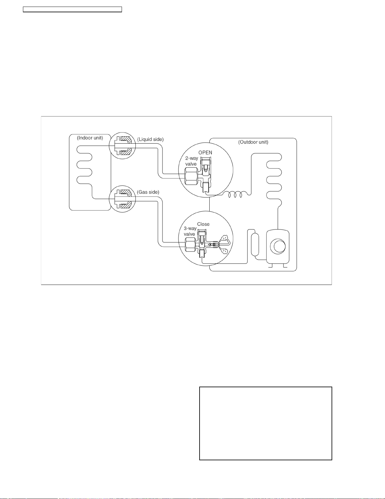
CS-A9CKPG CU-A9CKP6G / CS-A12CKPG CU-A12CKP6G
12.1. Air Purging of the Piping and Indoor Unit
12.1.1. Air purging (Installation)
Required tools: hexagonal wrench, adjustable wrench, torque
wrenches, wrench to hold the joints and gas leak detector.
The additional gas for air purging has been charged in the
outdoor unit.
However, if the flare connections have not been done correctly
and there gas leaks, a gas cylinder and the charge set will be
needed.
The air in the indoor unit and in the piping must be purged. If air
remains in the refrigeration pipings, it will affect the
compressor, reduce the cooling capacity, and could lead to a
malfunction.
Service port cap
Be sure, using a torque wrench to tighten the service port cap (after using the service port), so that it prevents the gas
leakage from the refrigeration cycle.
Procedure:
Recheck the piping connections.
1.
Open the valve stem of the 2-way valve counter-
2.
clockwise approximately 90°, wait 10 seconds, and
then set it to closed position.
Be sure to use a hexagonal wrench to operate the valve
•
stem.
Check for gas leakage.
3.
Check the flare connection for gas leakage.
•
Purge the air from the system
4.
Set the 2-way valve to the open position and remove the
•
cap from the 3-way valve’s service port.
Using the hexagonal wrench to press the valve core pin,
•
discharge for three seconds and then wait for one
minute.
Repeat this three times.
Use torque wrench to tighten the service port cap to a
5.
Set the 3-way valve to the opened position.
6.
Mount the valve stem nuts to the 2-way and 3-way
7.
valves.
Check for gas leakage.
8.
At this time, especially check for gas leakage from the 2-
•
way and 3-way’s stem nuts, and from the service port
cap.
Caution
If gas leakage is discovered in step (3) above, take
the following measures:
If the leaks stop when the piping connections are
tightened further, continue working from step (4).
If the gas leaks do not stop when the connections are
retightened, repair the location of the leak, discharge
all of the gas through the service port, and then
recharge with the specified amount of gas from a gas
cylinder.
torque of 1.8 kg.m. (18 N.m).
56
Page 57

12.1.2. Pumping down (Re-installation)
CS-A9CKPG CU-A9CKP6G / CS-A12CKPG CU-A12CKP6G
Procedure:
Confirm that both the 2-way and 3-way valves are set to
1.
the opened position.
Remove the valve stem caps and confirm that the valve
•
stems are in the opened position.
Be sure to use a hexagonal wrench to operate the valve
•
stems.
Operate the unit for 10 to 15 minutes.
2.
Stop operation and wait for 3 minutes, then connect the
3.
charge set to the service port of the 3-way valve.
Connect the charge hose with the push pin to the Gas
•
service port.
Air purging of the charge hose.
4.
Open the low-pressure valve on the charge set slightly
•
to purge air from the charge hose.
Set the 2-way valve to the close position.
5.
Operate the air conditioner at the cooling cycle and
6.
stop it when the gauge indicates 1 kg/cm
Immediately set the 3-way valve to the closed position.
7.
Do this quickly so that the gauge ends up indicating 3 to
•
5 kg/cm
Disconnect the charge set, and mount the 2-way and 3-
8.
2
G (0.3 to 0.5 MPa).
2
G (0.1 MPa).
way valve’s stem nuts and the service port caps.
Use a torque wrench to tighten the service port cap to a
•
torque of 1.8 kg.m (18 N.m).
Be sure to check for gas leakage.
•
57
Page 58

CS-A9CKPG CU-A9CKP6G / CS-A12CKPG CU-A12CKP6G
12.1.3. Re-air purging (Re-installation)
Procedure:
Confirm that both the 2-way and 3-way valves are set to
1.
the closed position.
Connect the charge set and a charging cylinder to the
2.
service port of the 3-way valve.
Leave the valve on the charging cylinder closed.
•
Air purging.
3.
Open the valves on the charging cylinder and the
•
charge set. Purge the air by loosening the flare nut on
the 2-way valve approximately 45° for 3 seconds then
closing it for 1 minute; repeat 3 times.
After purging the air, use a torque wrench to tighten the
•
flare nut on the 2-way valve.
Check for gas leakage.
4.
Check the flare connections for gas leakage.
•
Discharge the refrigerant.
5.
Close the valve on the charging cylinder and discharge
•
the refrigerant until the gauge indicates 3 to 5 kg/cm
(0.3 to 0.5 MPa)
Disconnect the charge set and the charging cylinder,
6.
and set the 2-way and 3-way valves to the open
position.
Be sure to use a hexagonal wrench to operate the valve
•
stems.
Mount the valve stem nuts and the service port cap.
7.
Be sure to use a torque wrench to tighten the service
•
port cap to a torque 1.8 kg.m (18 N.m).
Be sure to check for gas leakage.
•
2
G
58
Page 59

12.1.4. Balance refrigerant of the 2-way, 3-way valves
(Gas leakage)
CS-A9CKPG CU-A9CKP6G / CS-A12CKPG CU-A12CKP6G
Procedure:
Confirm that both the 2-way and 3-way valves are set to
1.
the open position.
Connect the charge set to the 3-way valve’s service
2.
port.
Leave the valve on the charge set closed.
•
Connect the charge hose with the push pin to the
•
service port.
Open the valves (Low side) on the charge set and
3.
discharge the refrigerant until the gauge indicates 0.5
to 1 kg/cm
•
2
G (0.05 to 0.1 MPa) .
If there is no air in the refrigeration cycle [the pressure
when the air conditioner is not running is higher than 1
2
kg/cm
G (0.1 MPa)], discharge the refrigerant until the
gauge indicates 0.5 to 1 kg/cm
2
G (0.05 to 0.1 MPa). If
this is the case, it will not be necessary to apply a
evacuation.
Discharge the refrigerant gradually; if it is discharged
•
too suddenly, the refrigeration oil will be discharged.
59
Page 60

CS-A9CKPG CU-A9CKP6G / CS-A12CKPG CU-A12CKP6G
12.1.5. Evacuation (Installation)
(No refrigerant in the refrigeration cycle)
Procedure:
Connect the vacuum pump to the charge set’s centre
1.
hose.
Evacuation for approximately one hour.
2.
Confirm that the gauge needle has moved toward -0.1
•
MPa (-76 cmHg) [vacuum of 4 mmHg or less.]
Close the valve (Low side) on the charge set, turn off
3.
the vacuum pump, and confirm that the gauge needle
does not move (approximately 5 minutes after turning
off the vacuum pump).
Disconnect the charge hose from the vacuum pump.
4.
Vacuum pump oil
•
If the vacuum pump oil becomes dirty or depleted,
replenish as needed.
60
Page 61

12.1.6. Gas charging
(After Evacuation)
CS-A9CKPG CU-A9CKP6G / CS-A12CKPG CU-A12CKP6G
Procedure:
Connect the charge hose to the charging cylinder.
1.
Connect the charge hose which you disconnected from
•
the vacuum pump to the valve at the bottom of the
cylinder.
Purge the air from the charge hose.
2.
Open the valve at the bottom of the cylinder and press
•
the check valve on the charge set to purge the air (be
careful of the liquid refrigerant).
Open the valve (Low side) on the charge set and charge
3.
the system with liquid refrigerant.
If the system cannot be charged with the specified
•
amount of refrigerant, it can be charged with a little at a
time (approximately 150 g each time) while operating
the air conditioner in the cooling cycle; however, one
time is not sufficient, wait approximately 1 minute and
then repeat the procedure. (pumping down-pin)
This is different from previous procedures. Because you are
charging with liquid refrigerant from the gas side, absolutely do
no attempt to charge with large amount of liquid refrigerant
while operating the air conditioner.
Immediately disconnect the charge hose from the 3-
4.
way valve’s service port.
Stopping partway will allow the refrigerant to be
•
discharged.
If the system has been charged with liquid refrigerant
•
while operating the air conditioner, turn off the air
conditioner before disconnecting the hose.
Mount the valve stem caps and the service port cap.
5.
Use torque wrench to tighten the service port cap to a
•
torque of 18 N.m.
Be sure to check for gas leakage.
•
61
Page 62

•
•
CS-A9CKPG CU-A9CKP6G / CS-A12CKPG CU-A12CKP6G
13 Servicing Information
Caution:
Pb free solder has a higher melting point than standard solder; Typically the melting point is 50 - 70°F (30 - 40°C) higher. Please use
•
13.1. Indoor Electronic Controllers Removal Procedures
1. The Electronic Controller, a Signal Receiver and an
a high temperature soldering iron. In case of the soldering iron with temperature control, please set it to 700 ± 20°F (370 ± 10°C).
Pb free solder will tend to splash when heated too high (about 1100° F/600°C).
•
Indicator (Fig. 3) can be seen by the below steps:
Remove the 2 caps and 2 screws at the bottom of the
•
Front Grille. (Fig. 1)
Remove the Front Grille by releasing the 2 hooks at the
•
top of the Front Grille. (Fig. 1)
Fig. 1
Remove the Control Board Cover by releasing the 2
•
tabs at left, 1 tab on top and 1 tab at right side of the
Control Board Cover. (Fig. 2)
Fig. 2
2. To remove the Electronic Controller:
Release the Particular Piece. (Fig. 3)
•
Release the hook that hold the Electronic Controller.
•
(Fig. 3)
Fig. 3
13.2. Indoor Fan Motor and Cross Flow Fan Removal Procedures
Remove the Control Board by:-
•
Releasing CN-REC/DISP connectors. (Fig. 4)
−
Releasing CN-FM connectors. (Fig. 4)
−
Releasing CN-STM connector. (Fig. 4)
−
Removing the Earth Wire screw. (Fig. 4)
−
Releasing the Intake Air Sensor. (Fig. 4)
−
Releasing the Piping Sensor. (Fig. 4)
−
Fig. 4
62
Page 63

Pulling out the Drain Hose from outlet to remove the
−
Discharge Grille. (Fig. 5)
Removing the right and left screws. (Fig. 5)
−
Then remove the Control Board by pressing down the
−
hook at the left and pushing up the right hook. (Fig. 5)
Release the Fan Motor leadwire by pressing the hook at
−
the center of the connector. (Fig. 6)
CS-A9CKPG CU-A9CKP6G / CS-A12CKPG CU-A12CKP6G
Fig. 5
Remove the screw at the Cross Flow Fan. (Fig. 7)
−
REMINDER - To reinstall the Fan Motor, adjust the
−
connector of the Fan Motor as shown in the Fig. 7.
Fig. 6
Fig. 7
63
Page 64

CS-A9CKPG CU-A9CKP6G / CS-A12CKPG CU-A12CKP6G
Remove the screws at the left of the Evaporator. (Fig. 8)
−
Fig. 8
Remove the Bearing. (Fig. 9)
−
Push up the Evaporator and pull out the Cross Flow Fan
−
from shaft. By then, Fan Motor can be taken out. (Fig. 9)
Fig. 9
64
Page 65

Remote Control Reset
•
When the batteries are inserted for the first time, or the
batteries are replaced, all the indications will blink and the
remote control might not work.
If this happen, remove the cover of the remote control and
you will find a resetting terminal, and by shorting it with a
minus screwdriver, it will return to normal.
Changing the wireless remote control transmission
•
code
When two indoor units are installed in the same room, in
order to prevent operating errors caused by using two
remote controls, cut a jumper wire at the remote control
printed circuit board (J - A) and cut a jumper wire at the
indoor printed circuit board (JX4). It is possible to select
from 4 types of transmission codes including one at time of
delivery condition (0).
CS-A9CKPG CU-A9CKP6G / CS-A12CKPG CU-A12CKP6G
65
Page 66

CS-A9CKPG CU-A9CKP6G / CS-A12CKPG CU-A12CKP6G
14 Troubleshooting Guide
14.1. Refrigeration cycle system
In order to diagnose malfunctions, make sure that there are no
electrical problems before inspecting the refrigeration cycle.
Such problems include insufficient insulation, problem with the
power source, malfunction of a compressor and a fan.
The normal outlet air temperature and pressure of the
refrigeration cycle depends on various conditions, the standard
values for them are shown in the table to the right.
66
Page 67

•
•
•
•
•
•
•
CS-A9CKPG CU-A9CKP6G / CS-A12CKPG CU-A12CKP6G
14.1.1. Relationship between the condition of the air conditioner and pressure and
electric current
Cooling Mode Heating Mode
Condition of the air
conditioner Low Pressure High Pressure Electric current
during operation
Insufficient refrigerant
(gas leakage)
Clogged capillary tube
or Strainer
Short circuit in the
indoor unit
Heat radiation
deficiency of the
outdoor unit
Low Pressure High Pressure Electric current
during operation
Inefficient compression
•
Carry out the measurements of pressure, electric current, and temperature fifteen minutes after an operation is started.
14.1.2. Diagnosis methods of a malfunction of a compressor and 4-way valve
Nature of fault Symptom
•
Insufficient compressing of a compressor
Locked compressor
Insufficient switches of the 4-way valve
Electric current during operation becomes approximately 20% lower than the normal value.
•
The discharge tube of the compressor becomes abnormally hot (normally 70 to 90°C [158 to
194°F]).
•
The difference between high pressure and low pressure becomes almost zero.
•
Electric current reaches a high level abnormally, and the value exceeds the limit of an
ammeter. In some cases, a breaker turns off.
•
The compressor is a humming sound.
•
Electric current during operation becomes approximately 80% lower than the normal value.
•
The temperature different between from the discharge tube to the 4-way valve and from
suction tube to the 4-way valve becomes almost zero.
67
Page 68

CS-A9CKPG CU-A9CKP6G / CS-A12CKPG CU-A12CKP6G
15 Technical Data
68
Page 69

CS-A9CKPG CU-A9CKP6G / CS-A12CKPG CU-A12CKP6G
69
Page 70

CS-A9CKPG CU-A9CKP6G / CS-A12CKPG CU-A12CKP6G
70
Page 71

16 Exploded View
CS-A9CKPG CU-A9CKP6G / CS-A12CKPG CU-A12CKP6G
Note:
The above exploded view is for the purpose of parts disassembly and replacement.
The non-numbered parts are not kept as standard service parts.
71
Page 72

CS-A9CKPG CU-A9CKP6G / CS-A12CKPG CU-A12CKP6G
17 Replacement Parts List
<Model: CS-A9CK / CS-A12CK>
REF. NO. PART NAME & DESCRIPTION QTY. CS-A9CK CS-A12CK REMARKS
1 CHASSY COMPLETE 1 CWD50C1257
2 FAN MOTOR 1 CWA921143
3 CROSS FLOW FAN COMPLETE 1 CWH02C1012
4 BEARING ASS’Y 1 CWH64K007
5 SCREW - CROSS FLOW FAN 1 CWH4580304
6 EVAPORATOR 1 CWB30C1270 CWB30C1269
7 FLARE NUT 1 CWH6002140(1/4”)
8 FLARE NUT 1 CWT25005 (3/8”) CWT25007 (1/2”)
9 INTAKE AIR SENSOR HOLDER 1 CWH32142
10 DISCHARGE GRILLE COMPLETE 1 CWE20C2166
11 VERTICAL VANE 12 CWE241068
12 CONNECTING BAR 2 CWE261024
13 AIR SWING MOTOR 1 CWA98260
14 LEAD WIRE - AIR SWING MOTOR 1 CWA67C3977
15 CAP - DRAIN TRAY 1 CWH52C1001
16 HORIZONTAL VANE 1 CWE241070
17 PARTICULAR PIECE 1 CWD932162
18 CONTROL BOARD 1 CWH102103B
19 TERMINAL BOARD COMPLETE 1 CWA28C2167
20 POWER SUPPLY CORD 1 - 21 ELECTRONIC CONTROLLER - MAIN 1 CWA742987 CWA742988 0
22 LEAD WIRE - FAN MOTOR 1 CWA67C3961
23 ELECTRONIC CONTROLLER - RECEIVER 1 CWA742724
24 SENSOR COMPLETE 1 CWA50C2135
25 CONTROL BOARD FRONT COVER 1 CWH131090
26 ELECTRONIC CONTROLLER - INDICATOR 1 CWE39C1068
27 LEAD WIRE - INDICATOR 1 CWA67C3637
28 INDICATOR HOLDER 1 CWD932163
29 CONTROL BOARD TOP COVER 1 CWH131091
30 REMOTE CONTROL COMPLETE 1 (1)
31 FRONT GRILLE COMPLETE 1 (1)
32 INTAKE GRILLE 1 CWE221036A
33 CONTROL PANEL 1 CWE312300
34 DECORATION BASE (R) 1 CWE351067
35 DECORATION BASE (L) 1 CWE351068
36 GRILLE DOOR 1 CWE141047
37 AIR FILTER 2 (1)
38 SCREW - FRONT GRILLE 2 XTN4+16C
39 CAP - FRONT GRILLE 2 CWH521062
40 DRAIN HOSE 1 (1)
41 INSTALLATION PLATE 1 CWH36K1006
42 BAG COMPLETE - INSTALLATION SCREW 1 CWH82C067
43 AIR PURIFYING FILTER 1 (1)
44 SOLAR DEODORIZING FILTER 1 CWMD00C0002
45 FULCRUM 1 CWH621013
(2)
(2)
(2)
(2)
(2)
CWA75C2335
CWA75C2359
CWE11C2713
CWE11C2755
CWD001047
CWD001098
CWH851044
CWH85287
CWD00C1088
CWMD00C0001
←
←
←
←
←
←
←
←
←
←
←
←
←
←
←
←
←
←
←
←
←
←
←
←
←
←
←
←
←
←
←
←
←
←
←
←
←
←
←
←
←
←
←
←
←
←
0
0
0
0
0
0
0
0
0
(Note)
All parts are supplied from MAICO, Malaysia (Vendor Code: 061).
•
“O” marked parts are recommended to be kept in stock.
•
(1) — CS-A9CKPG-4, CS-A12CKPG-4 (USA).
•
(2) — CS-A9CKPG-5, CS-A12CKPG-5 (Canada).
•
72
Page 73

18 Exploded View
CS-A9CKPG CU-A9CKP6G / CS-A12CKPG CU-A12CKP6G
Note:
The above exploded view is for the purpose of parts disassembly and replacement.
The non-numbered parts are not kept as standard service parts.
73
Page 74

CS-A9CKPG CU-A9CKP6G / CS-A12CKPG CU-A12CKP6G
19 Replacement Parts List
<Model: CU-A9CK / CU-A12CK>
REF. NO. PART NAME & DESCRIPTION QTY. CU-A9CK CU-A12CK REMARKS
1 CHASSY ASS’Y 1 CWD50K2081A
2 SOUND PROOF MATERIAL 1 CWG302125 CWG302154
3 FAN MOTOR BRACKET 1 CWD541030
4 SCREW - FAN MOTOR BRACKET 2 CWH55413
5 FAN MOTOR 1 CWA951247
6 SCREW - FAN MOTOR MOUNT 3 CWH55406
7 PROPELLER FAN ASS’Y 1 CWH03K1006
8 NUT - PROPELLER FAN 1 CWH56053
9 COMPRESSOR 1 2R13S126A6J 2P19S126C1A 0
10 ANTI - VIBRATION BUSHING 3 CWH50077
11 NUT - COMPRESSOR MOUNT 3 CWH56000
12 CONDENSER 1 CWB32C1292 CWB32C1266
13 4-WAY VALVE 1 CWB001034 CWB001035 0
14 STRAINER 1 CWB11025
15 HOLDER COUPLING ASS’Y 1 CWH351015A
16 2-WAY VALVE (LIQUID) 1 CWB021055
17 3-WAY VALVE (GAS) 1 CWB011104 CWB011105 0
18 OVERLOAD PROTECTOR 1 CWA121113 CWA121114 0
19 HOLDER - O.L.P. 1 CWH7041200
20 TERMINAL COVER 1 CWH171011
21 NUT - TERMINAL COVER 1 (1)
22 SOUND PROOF BOARD 1 CWH151022A CWH151023A
23 CONTROL BOARD 1 CWH102186
24 TERMINAL BOARD ASS’Y 1 CWA28K1037
25 CAPACITOR - COMPRESSOR 1 CWA312064
26 HOLDER CAPACITOR 1 CWH30057 CWH30060
27 CAPACITOR - FAN MOTOR 1 CWA31270
28 CABINET SIDE PLATE (L) 1 CWE041044A
29 CABINET SIDE PLATE (R) 1 CWE041043A CWE041073A
30 CABINET FRONT PLATE 1 CWE06K1036
31 WIRE NET 1 CWD041028A CWD041038A
32 CABINET TOP PLATE 1 CWE031018A
33 PLATE - C. B. COVER 1 CWH131088
34 CONTROL BOARD COVER 1 CWH131092
35 HANDLE 1 CWE161010
36 OPERATION INSTRUCTIONS 1 (1)
37 INSTALLATION INSTRUCTIONS 1 CWF612346
40 L-TUBE 1 CWH5850080
41 TUBE ASS’Y (CHECK VALVE/CAPILLARY) 1 CWT01C2681 CWT01C2679
42 ELECTRO MAGNETIC SWITCH 1 K6A1ALA00001
43 ELECTROLYTIC CAPACITOR 1 CWA32C067
44 ELECTRO MAGNETIC SWITCH 1 K6C2CLA00001
45 TEMPERATURE RELAY 1 CWA14C1009
46 V-COIL COMPLETE 1 CWA43C2113
47 MAGNET RELAYS 1 K6C1CLA00001
48 THERMOSTAT 1 CWA151035
49 TERMINAL BOARD ASS’Y 1 CWA28K1055
CWH56053
(2)
CWH7080300
(35µF, 370VAC)
(8.0µF, 230VAC)
CWF563841
(2)
CWF563842
←
←
←
←
←
←
←
←
←
←
←
←
←
←
←
←
←
←
XS371506FP-B
(50µF, 370VAC)
←
←
←
←
←
←
←
←
←
←
←
←
←
←
←
←
←
←
←
0
0
0
0
0
0
0
0
0
(Note)
All parts are supplied from MAICO, Malaysia (Vendor Code: 061).
•
“O” marked parts are recommended to be kept in stock.
•
(1) — CU-A9CKP6G-4, CU-A12CKP6G-4 (USA).
•
(2) — CU-A9CKP6G-5, CU-A12CKP6G-5 (Canada).
•
74
Page 75

20 Electronic Circuit Diagram
• CS-A9CK / CU-A9CK
• CS-A12CK / CU-A12CK
SCHEMATIC DIAGRAM 1/3
MAIN
R12
R08
5.1k
1k
C02
0.01
RECEIVER
R11
CS-A9CKPG CU-A9CKP6G / CS-A12CKPG CU-A12CKP6G
C01
R07
0.01
1k
10k
INDICATOR
POWER
QUIET
TIMER
ECONOMY
POWERFUL
3
2
1
5
4
SW101
AUTO
12
GRN
ORG
ORG
GRN
ORG
D101
D102
D103
D104
D105
(MX3)
CN-RCV1
1
2
3
—
CN-DISP
AIR TEMP. SENSOR
(15k 3950)
PIPE TEMP. SENSOR
(20k 3950)
AIR SWING
MOTOR
(ZH5)
D05
R18
D06
R19
D07
R20
D08
R21
D09
R22
D10
R23
D11
R24
D12
C27 0.01
R59
1k
C04
0.1
9
10 7
11 6
12 5
8
R25
R13
220
R14
330
R15
330
R16
110
R17
330
C28
R33
C08
15k
0.1
8
1RS
R/B
Vcc GND 7
2
3
g
f
e
413
d
314
c
215
b
116
a
CS
C05
SK4
0.1
IC02
6
D0
5
D1
C29
(PH10)
CN-DISP
10
9
8
1
7
2
6
5
3
4
4
3
5
2
6
7
1
C23
0.01
R60
10k
C24 0.01
C25 0.01
C26 0.01
R06
24k
(XH4)
CN-HA
4
3
2
1
(PH4)
CN-TH
1
2
3
4
RY-PWR
RY-HOT
(PH5)
CN-STM
1
1
2
2
3
3
4
4
55
C22
R58
10k
0.01
R30
20k
R05
R04
43 /2W
43 /2W
IC05
A52A2003GR
STEPPING MOTOR DRIVE
75
Page 76

CS-A9CKPG CU-A9CKP6G / CS-A12CKPG CU-A12CKP6G
SCHEMATIC DIAGRAM 2/3
TEST
Q01
4.7k
c
10k
e
b
BZ1
R55
1k
10k
BZ
1k
R02
R01
10
11
12
13
14
15
16
1
2
3
4
5
6
7
8
9
P50/A8
P51/A9
P52/A10
P53/A11
P54/A12
P55/A13
P56/A14
P57/A15
Vss0
VDD0
P30
P31
P32
P33
P34
P35
64
63
P46/AD6
P47/AD7
RY-PWR DRIVE SIGNAL
AUTO RESTART
P36
P20/S1
18
17
62
P45/AD5
DISPLAY
P21/S0
19
61
P44/AD4
P22/SCK
60
59
P42/AD2
P43/AD3
A52D0022GB75
P25
P24
P23
222120
58
57
56
P67
P40/AD0
P41/AD1
STEPPING
MOTOR
DRIVE
SIGNAL
BUZZER
IC01
INTAKE AIR TEMP
PIPE TEMP
DEICE
DETECTION
GROUND
AVss
VDD1
252423
55
54
53
P64
P65
P66
RY-HOT DRIVE SIGNAL
TIMER SHORTEN
FAN SPEED
DRIVE SIGNAL
AUTO OPERATION
TEST RUN
REMOTE CONTROL
SOUND
POWER CLOCK INPUT
REMOTE-CONTROL
COMMAND INPUT
P15/AN5
P16/AN6
P17/AN7
282726
52
P75
P14/AN4
51
P74
RESET
POWER
P13/AN3
OSC
313029
R10
10k
50
P73
P03/INTP3
P02/INTP2
P01/INTP1
P00/INTP0
P11/AN1
P12/AN2
Q02
b
49
P72
P71
48
P70
47
46
45
44
43
Vss1
42
X1
41
X2
40
39
IC
38
XT1
37
XT2
Reset
36
35
AVd0
AVref
34
P10
33
/ANO
32
4.7k
Q03
b
4.7k
SSR02
c
10k
e
SSR01
c
10k
e
C06
R34
0.1
51k
R32
150k
X01
C10
0.1
4.096MHz
(47pF X 2)
R31
R56
0.01
C16
R41
1.0k
R44
1k
POWER CLOCK
c
e
T01
5
8
2
13
Q04
GENERATOR
b
JX1
JX2
R09
10k
R37
R38
10k
REMOTE CONTROL NO.
JX3 JX4 RX1
0
SHORT
1
SHORT
2
OPEN
SHORT
3
SHORT
OPEN
OPEN
OPEN
0.01
C15
JX4
10K
10K
76
Page 77

SCHEMATIC DIAGRAM 3/3
CS-A9CKPG CU-A9CKP6G / CS-A12CKPG CU-A12CKP6G
1
2
3
4
5
TO POWER
SUPPLY
{
R43
AC
RY-PWR
(WHT)
D13
+
C09
D14
IC04
REGULATOR
C17
3300
35V
(NHG)
R26
3.9k
C07
0.1
R36
1k
R35
10k
I
PC01
41
3
100
RB501V-40
16V
DB01
~
+
~
R03
820
R29
4.7k
C12
0.1
CT01
CR02
SSR02
IC03
REGULATOR
I
OO
C14
470
G
25V
R47
39k/2W
R48
510
2
5V12V
G
R57
39k/2W
RY-HOT
CR01
C11
100
16V
FUSE
C03
0.047
ZNR01
511U
L01
125 H
C19
0.047
CN-FM
ZD1
7.5EL1
R51
R50
R49
100k
1k
c
C18
b
0.1
e
Q05
RESET SIGNAL
GENERATION
10k
R52
6.2k
R53
10k
c
b
R54
e
6.2k
Q06
RESET SIGNAL
GENERATION
C21
10
50V
CN-FB1
3
2
1
(PH-3)
R40
10k
R42
24k
RX1
JX3
HOT(RED)
ZNR03
511U
SSR01
C-FM
2
FAN
MOTOR
FM(BLU)
5431
12345 LN
BR
B
BL
BL
V-COIL
COMPLETE
B
BL
THERMOSTAT
5
6
4
1
MAGNETIC RELAY
B
R
GR
W
3
67
O
MAGNETIC RELAY
314 28
B
567
Y
B
CAPACITOR
GR
OVER LOAD
PROTECTOR
Y
COMPRESSOR
R
CAPACITOR
B
BL
BL
28
BL
BR
FAN MOTOR
R
W
TRS
BL
B
W
BL
ELECTROLYTIC
MAGNETIC RELAY
B
GR
CAPACITOR
A
77
Page 78

CS-A9CKPG CU-A9CKP6G / CS-A12CKPG CU-A12CKP6G
78
Page 79

CS-A9CKPG CU-A9CKP6G / CS-A12CKPG CU-A12CKP6G
How to use electronic circuit diagram
TIMER TABLE
Test Mode
Name Time (When test point Remarks
Short-circuited)
Real Timer 1hr. 1min.
10 min. 10 sec.
1min. 1 sec.
Time Delay Safety Control 2 min. 58 sec. 0 sec.
Forced Operation 60 sec. 0 sec.
Time Save Control 7min. 4.2 sec.
Anti-Freezing 4min. 0 sec.
Auto Mode Judgement 25 sec. 0 sec.
Soft Dry OFF 6min. 36 sec.
ON 10 min. 60 sec. Soft Dry: 10 min. operation
Cooling 40 sec. 4 sec.
Deodorizing Control
Soft Dry 40 sec. 4 sec.
Comp. Reverse Rotation Detection 5min. 30 sec. Comp. ON 5 min. and above
Comp./ Fan Motor Delay Timer 1.6 sec. 0 sec.
Powerful Mode Operation 15 min. 15 sec.
Random Auto Restart Control 0 ~ 62 sec. 0 ~ 6.2 sec.
TRS Recovery Detection 12 min. 72 sec.
Time Save Control (Heating) 30 min. 3 sec.
4 Way Valve Control (Delay) 5min. 30 sec.
Deice Operation Occurs 60 min. 6 sec. 60 min. after previous deice
Overload Deice Timer 1min. 6 sec. Comp. ON continuously for 1 min. check
Deice End 12 min. 72 sec. Max. Operation time
Deice Operation (Extend) 60 sec. 0 sec.
Hotstart Finish 30 sec. 0 sec.
70 sec. 7 sec.
20 sec. 2 sec.
180 sec. 18 sec.
360 sec. 36 sec.
2min. 0 sec.
6min. 36 sec.
3min. 18 sec.
1min. 6 sec.
4min. 24 sec. Continuously 4 min. Comp. ON
50 sec. 0 sec. TRS ON continuously for 50 sec. check
30 sec. 3 sec. 30 sec. Comp. OFF after deice
10 sec. 1 sec. 4-Way Valve ON 10 sec. later after deice
120 sec. 0 sec.
180 sec. 0 sec.
79
Page 80

CS-A9CKPG CU-A9CKP6G / CS-A12CKPG CU-A12CKP6G
20.1. REMOTE CONTROL
80
Page 81

20.2. PRINT PATTERN
INDOOR UNIT PRINTED CIRCUIT BOARD
TOP VIEW
CS-A9CKPG CU-A9CKP6G / CS-A12CKPG CU-A12CKP6G
81
Page 82

CS-A9CKPG CU-A9CKP6G / CS-A12CKPG CU-A12CKP6G
20.3. PRINT PATTERN
INDOOR UNIT PRINTED CIRCUIT BOARD
BOTTOM VIEW
82
[MAICO] Printed in Malaysia
 Loading...