

Page 1
Order No:
Room Air Conditioner
CS-A28BKP5/CU-A28BKP5
CONTENTS
Page Page
1 Features 2
2 Functions
3 Product Specifications
4 Dimensions
5 Refrigeration Cycle Diagram
6 Block Diagram
7 Wiring Diagram
8 Operation Details
9 Operating Instructions
10 Installation Instructions
11 3-way Valve 51
3
12 Servicing Information
6
13 Troubleshooting Guide
14 Technical Data
8
9
15 Exploded View
16 Replacemen t Parts List
10
11
17 Exploded View
12
18 Replacemen t Parts List
19 Electronic Parts List
22
42
20 Electronic Circuit Diagram
© 2002 Matsushita Air-Conditioning Corp. Sdn. Bhd.
(183914D) All rights reserved. Unauthorized copying
and distribution is a violation of law.
58
62
64
67
68
69
70
71
72
Page 2

CS-A28BKP5/CU-A28BKP5
1 Features
• High Efficiency
High Efficiency Airflow Circuit
•
Compact Design
•
Auto Restart after Power Failure
•
Long Piping up to 30m
•
• Catechin Deodorizing Air Filter
Deodorizing Control during operation
•
Cold draught Control
•
2
Page 3
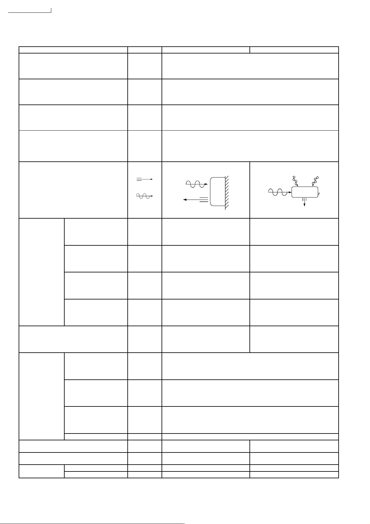
2 Functions
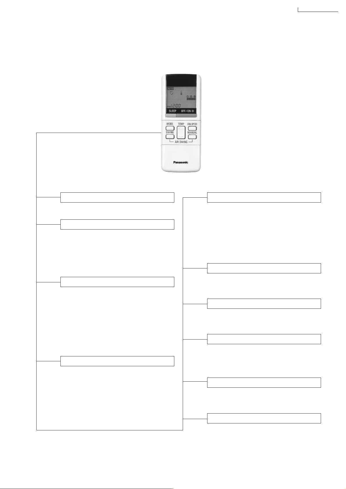
Remote Control
CS-A28BKP5/CU-A28BKP5
OFF / ON I
MODE
FAN SPEED
AIR SWING
Operation OFF / ON
Operation Mode Selection
•
•
•
•
AUTO
HEAT
COOL
DRY
Automatic Operation Mode
Heating Operation Mode
Cooling Operation Mode
Soft Dry Operation Mode
Indoor Fan Speed Selection
• h j k Low Speed
l
• h j k Medium Speed
lll
• h j k High Speed
lllll
•
AUTOFAN
Automatic Fan Speed
Airflow Direction Control
•
SWING
•
MANUAL
Automatic Airflow Direction
Control
Airflow Direction Manual
Control
TEMP.
ON-TIMER
OFF-TIMER
TIME
SET
CANCEL
CLOCK
(q)
Room Temperature Setting
• Temperature Setting (16˚C to 30˚C)
• Automatic Operation
m / n
n
n - o
2˚C lower than standard
Standard
2˚C higher than standard
Timer Operation Selection
• 24-hour, OFF / ON Real Timer Setting.
Time / Timer Setting
• Hours and minutes setting.
Timer Operation Set / Cancel
• ON Timer and OFF Timer setting and
cancellation.
Clock Setting
• Current time setting.
3
SLEEP
Sleep Mode Operation OFF / ON
Page 4
CS-A28BKP5/CU-A28BKP5
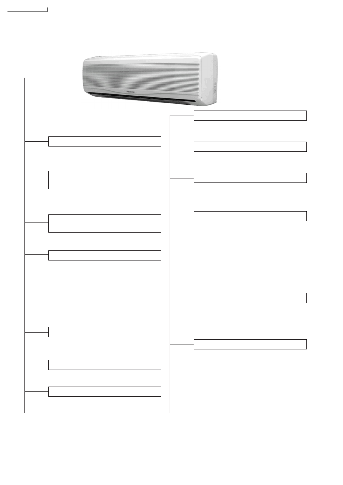
Indoor Unit
AUTO
OFF / ON
Auto Operation Switch
• Used when the remote control cannot be
used.
Auto Restart Control
• Operation is restarted after power failure
at previous setting mode.
Anti-Freezing Control
• Anti-Freezing control for indoor heat
exchanger. (Cooling and Soft Dry)
TEST RUN
OFF / ON
Remote Control Signal Receiving
Sound Control
• It can be controlled by pressing Auto
Operation Switch for 10 seconds.
Operation Test Running / Pump
Down Switch
• Used when test running or servicing.
Operation Indication Lamps (LED)
•
POWER
(Red)........ Lights up in operation,
blinks in Automatic
Operation Mode judging
and Hot Start operation.
•
SLEEP
(Orange).... Lights up in Sleep
Mode Operation.
•
TIMER
(Orange).... Lights up in Timer
Setting.
Operation Mode
• Heating, Cooling, Soft Dry, and Automatic
Mode.
Time Delay Safety Control
• Restarting is inhibited for appro. 3 minutes.
7 Minutes Time Save Control
• Cooling Operation only.
Sleep Mode Auto Control
• Indoor Fan operates at Low fan
speed.
• Operation stops after 8 hours.
Indoor Fan Speed Control
• High, Medium and Low.
• Automatic Fan Speed Mode
– Heating : Fan speed varies from Hi
➝
SLo in accordance with
indoor heat exchanger.
– Cooling : Fan rotates at Hi and Me
speed. Deodorizing control
is available.
– Soft Dry: Fan rotates at Lo speed.
Airflow Direction Control
• Automatic air swing and manual adjusted
by remote control for vertical airflow.
• Manually adjusted by hand for horizontal
airflow.
Hot-Start Control
• The indoor fan stops until the indoor heat
exchanger temperature over 30°C.
• The indoor fan operates at SLo and Lo
when indoor heat exchanger temperature
reaches 30°C ~ 42°C.
• Hot start is completed when indoor heat
exchanger reaches 42°C.
4
Page 5
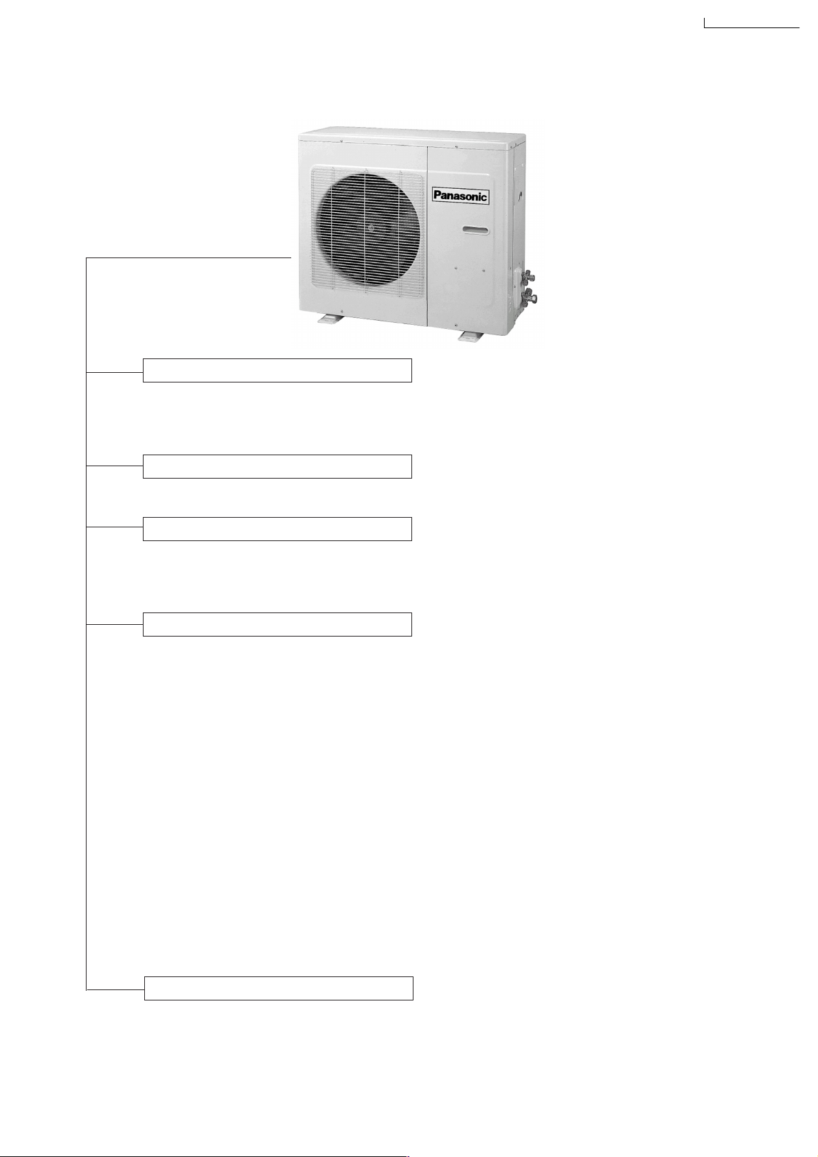
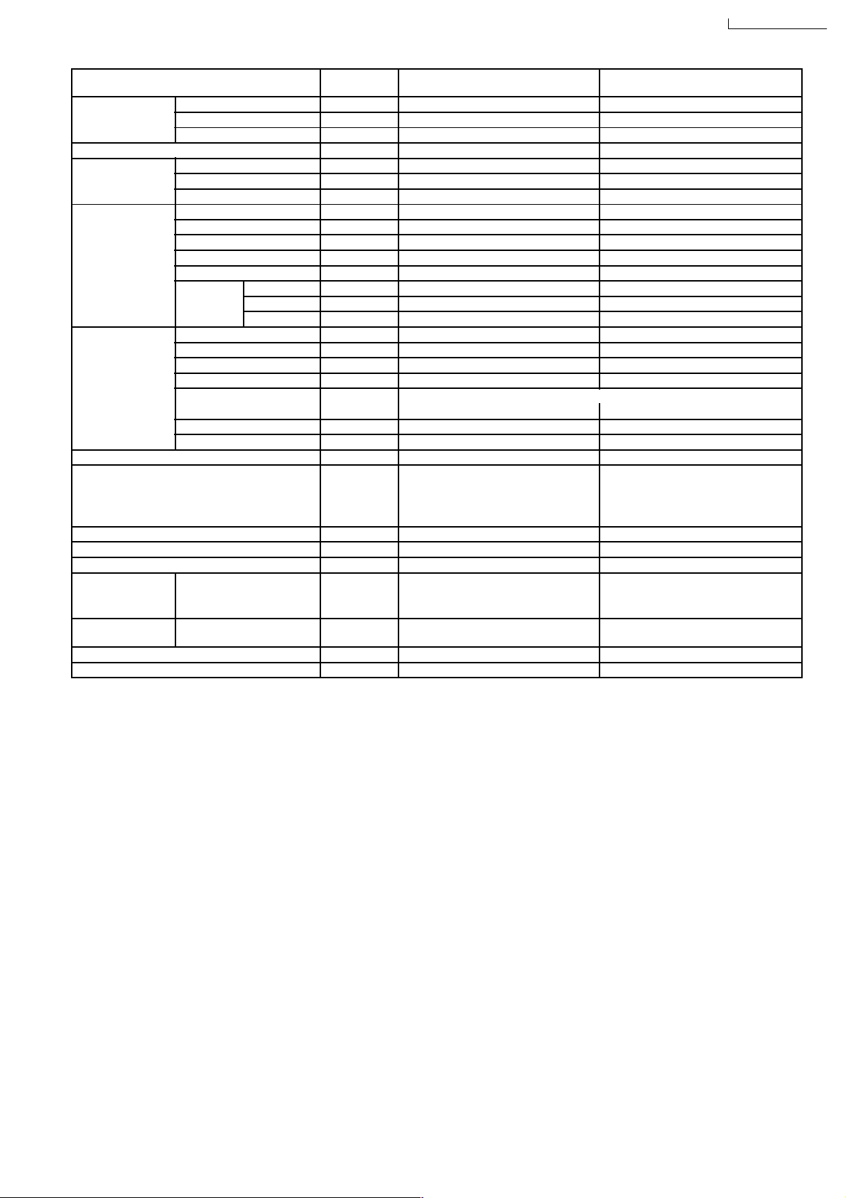
Outdoor Unit
4-Way Valve Control
• When the unit is switched to “OFF”
during Heating operation, 4-way valve
stays at Heating Position for 5 minutes.
CS-A28BKP5/CU-A28BKP5
Overload Protector
• Inner protector (Compressor, Fan Motor).
60 Secs. Forced Operation Control
• Once the compressor is activated, it
does not stop for 60 secs. (Stops immediately with remote control stop signal.)
Outdoor Fan Operation Control
•
4-pole induction motor (2-speed)
• For Cooling or Soft Dry Operation
Hi-speed … when outdoor temperature
reaches to 31°C
Lo-speed … when outdoor temperature
reaches to 29°C
• For Heating Operation
Hi-speed ... when outdoor temperature
reaches to 13.5°C.
Lo-speed ... when outdoor temperature
reaches to 15.5°C.
• For Over-heating Protection, the Fan is
switched ON or OFF depending on the
piping temperature and the outdoor
temperature.
Deice Control
•
To prevent frosting at outdoor heat
exchanger during Heating Operation.
5
Page 6
CS-A28BKP5/CU-A28BKP5
3 Product Specifications
Unit CS-A28BKP5 CU-A28BKP5
Cooling Capacity kW
Heating Capacity kW
Moisture Removal l/h
Power Source Phase
Airflow Method OUTLET
Air Volume Indoor Air (Lo) m3/min (cfm) Cooling; 14.2 (501) —
Btu/h
Btu/h
Pint/h
V
Cycle
SIDE VIEW TOP VIEW
INTAKE
Heating; 15.6 (551)
7.92 - 7.80
27,000 - 26,600
8.35 - 8.25
28,500 - 28,200
4.6
9.7
Single
230 - 220
50
Indoor Air (Me) m3/min (cfm) Cooling; 15.0 (530) —
Heating; 16.4 (579)
Indoor Air (Hi) m3/min (cfm) Cooling; 16.3 (575) —
Heating; 17.7 (625)
Outdoor Air m3/min (cfm) — Cooling; 59.0 (2,083)
Heating; 59.2 (2,090)
Noise Level dB (A) Cooling; 48/46/44 Cooling; 63/55
Heating; 48/44 Heating; 63/55
Electrical Data Input kW Cooling; 2.62 -2.60
Heating; 2.88 - 2.85
Running Current A Cooling; 12.2 - 12.5
Heating; 13.2 - 13..5
COP W/W Cooling; 3.0 - 3.0
Heating; 2.9 - 2.9
Starting Current A 76
Piping Connection Port
(Flare piping)
Pipe Size
(Flare piping)
Drain
Hose
Inner diameter mm 14 —
Length m 0.73 —
inch
inch
inch
inch
G ; Half Union 5/8”
L ; Half Union 1/4”
G (gas side); 5/8”
L (liquid side); 1/4”
6
G ; 3-way valve 5/8”
L ; 3-way valve 1/4”
G (gas side); 5/8”
L (liquid side); 1/4”
Page 7
CS-A28BKP5/CU-A28BKP5
Power Cord Length
Number of core-wire
m 2.1
3 (2.5 mm
2
)
—
—
Dimensions Height inch (mm) 14 - 9/16 (370) 26 - 31/32 (685)
Width inch (mm) 48 - 1/32 (1,220) 34 - 21/32 (880)
Depth inch (mm) 8 - 21/32 (220) 13 - 19/32 (345)
Net Weight lb (kg) 40 (18) 150 (68)
Compressor Type — Scroll type
Motor Type — Induction (2-poles)
Rated Output kW — 2.11
Air Circulation Type Cross-flow Fan Propeller Fan
Material AS + Glass Fiber 30% AS + Glass Fiber 20%
Motor Type Induction (4-poles) Induction (4-poles)
Input W — —
Rated Output W 40 100
Fan Speed Low rpm Cooling; 1,262 Heating; 1,250 920 - 880
Medium rpm Cooling; 1,322 Heating; 1,328 —
High rpm Cooling; 1,418 Heating; 1,420 1,200 - 1,170
Heat Exchanger Description Evaporator Condenser
Tube material Copper Copper
Fin material Aluminium Aluminium
Fin Type Louver Louver
Row / Stage (Plate fin configuration, forced draft)
2×10 2×26
FPI 18 18
Size (W × H × L) mm 966.5 × 254 × 44 826 × 663.9 × 44
Refrigerant Control Device — Capillary Tube
Refrigeration Oil (cm3) — SONTEX
200 LT (1,242)
Refrigerant (R-22) g (oz) — 1,800 (63.5)
Thermostat Electronic Control Electronic Control
Protection Device Inner Protector Inner Protector
Capillary Tube Length mm — Cooling; 850, Heating; 1,200
Flow Rate l/min — Cooling; 21.8, Heating; 23 (1/2 ATM)
Inner Diameter mm — Cooling; 2.0, Heating; 2.4
Air Filter Material
Style
A.B.S
Honeycomb
—
Compressor Capacitor µF, VAC — 50 µF, 370VAC
Fan Motor Capacitor µF, VAC 2.0 µF, 450VAC 3.0 µF, 450VAC
•
Specifications are subject to change without notice for further improvement.
7
Page 8
CS-A28BKP5/CU-A28BKP5
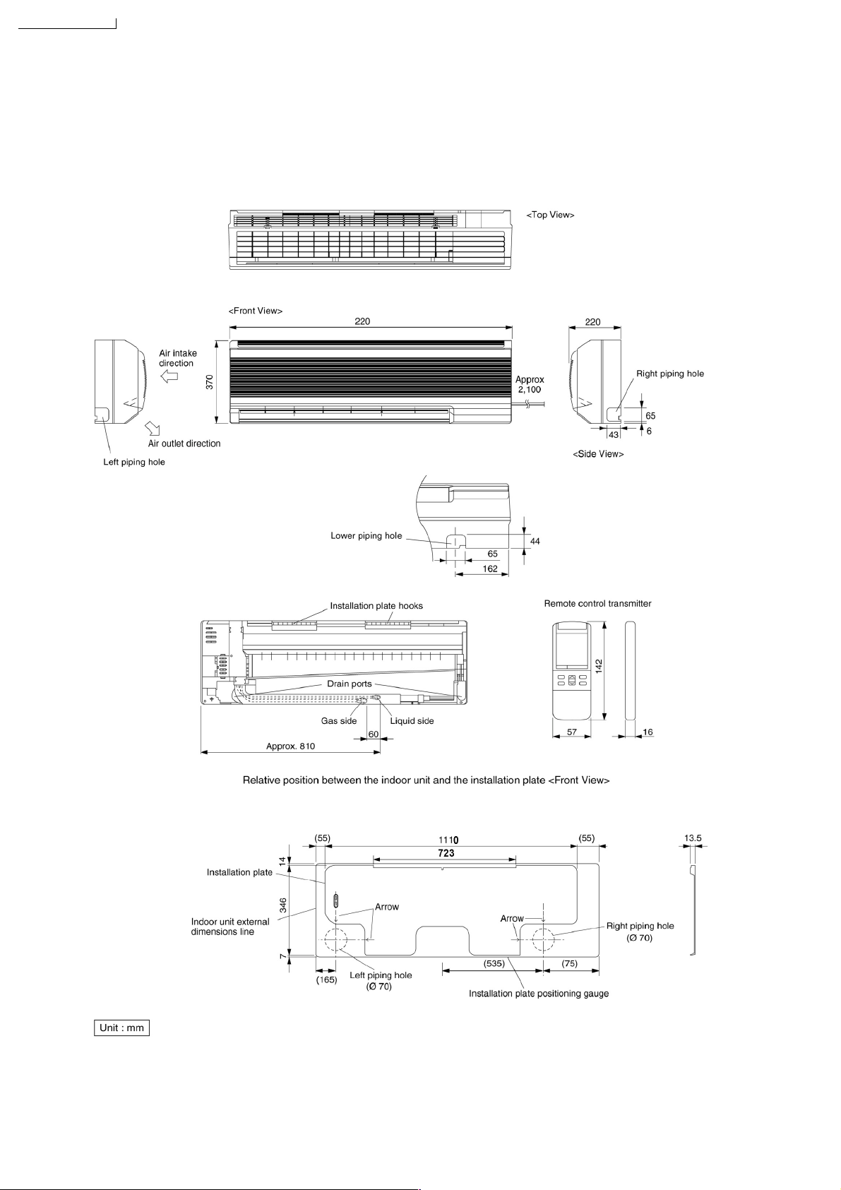
4 Dimensions
CS-A28BKP5/ CU-A28BKP5
8
Page 9
Dimensions
CS-A28BKP5/CU-A28BKP5
CS-A28BKP5/CU-A28BKP5
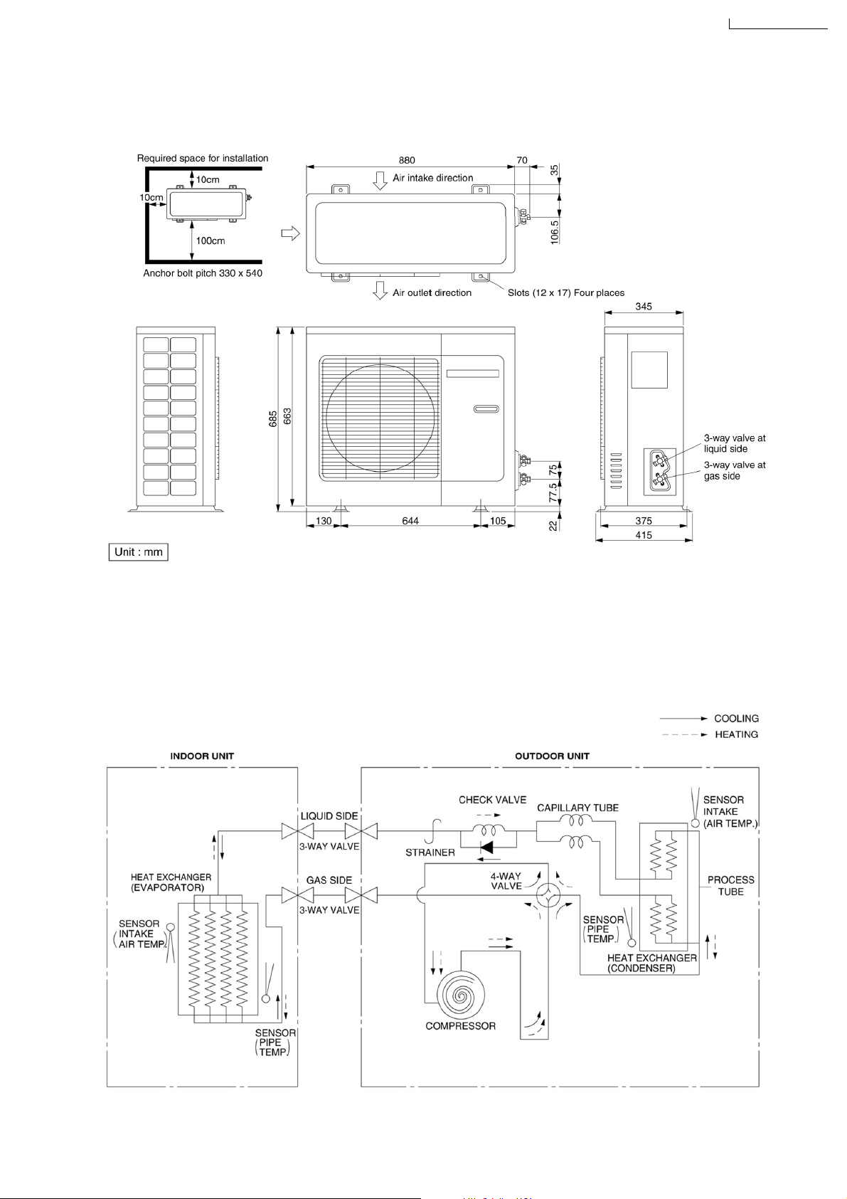
5 Refrigeration Cycle Diagram
CS-A28BKP5/CU-A28BKP5
CS-A28BKP5/CU-A28BKP5
9
Page 10
CS-A28BKP5/CU-A28BKP5
6 Block Diagram
CS-A28BKP5/CU-A28BKP5
10
Page 11
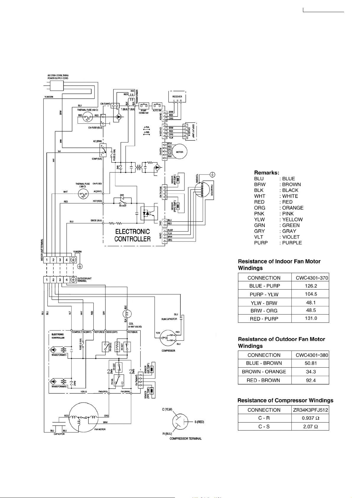
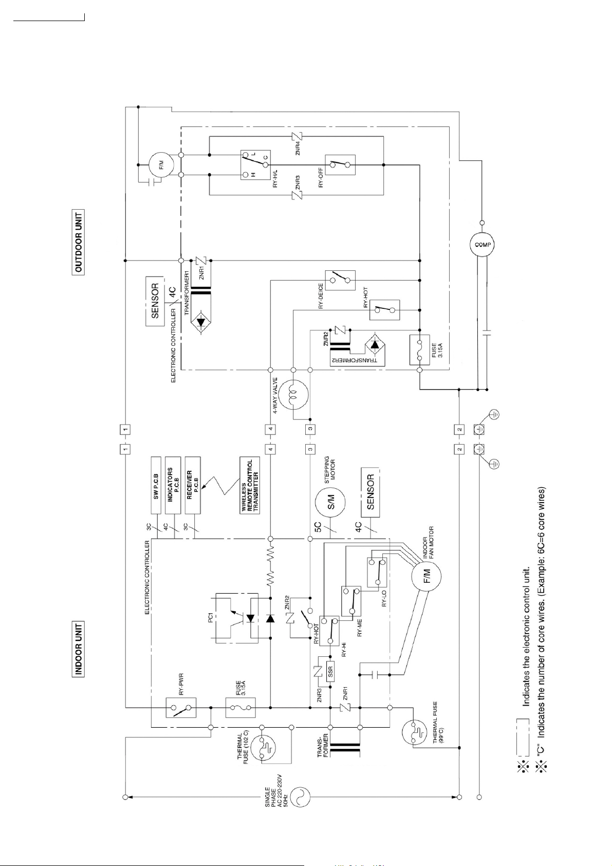
7 Wiring Diagram
CS-A28BKP5 / CU-A28BKP5
CS-A28BKP5/CU-A28BKP5
11
Page 12
CS-A28BKP5/CU-A28BKP5
8 Operation Details
8.1. Cooling Mode Operation
Cooling in operation according to Remote Control setting.
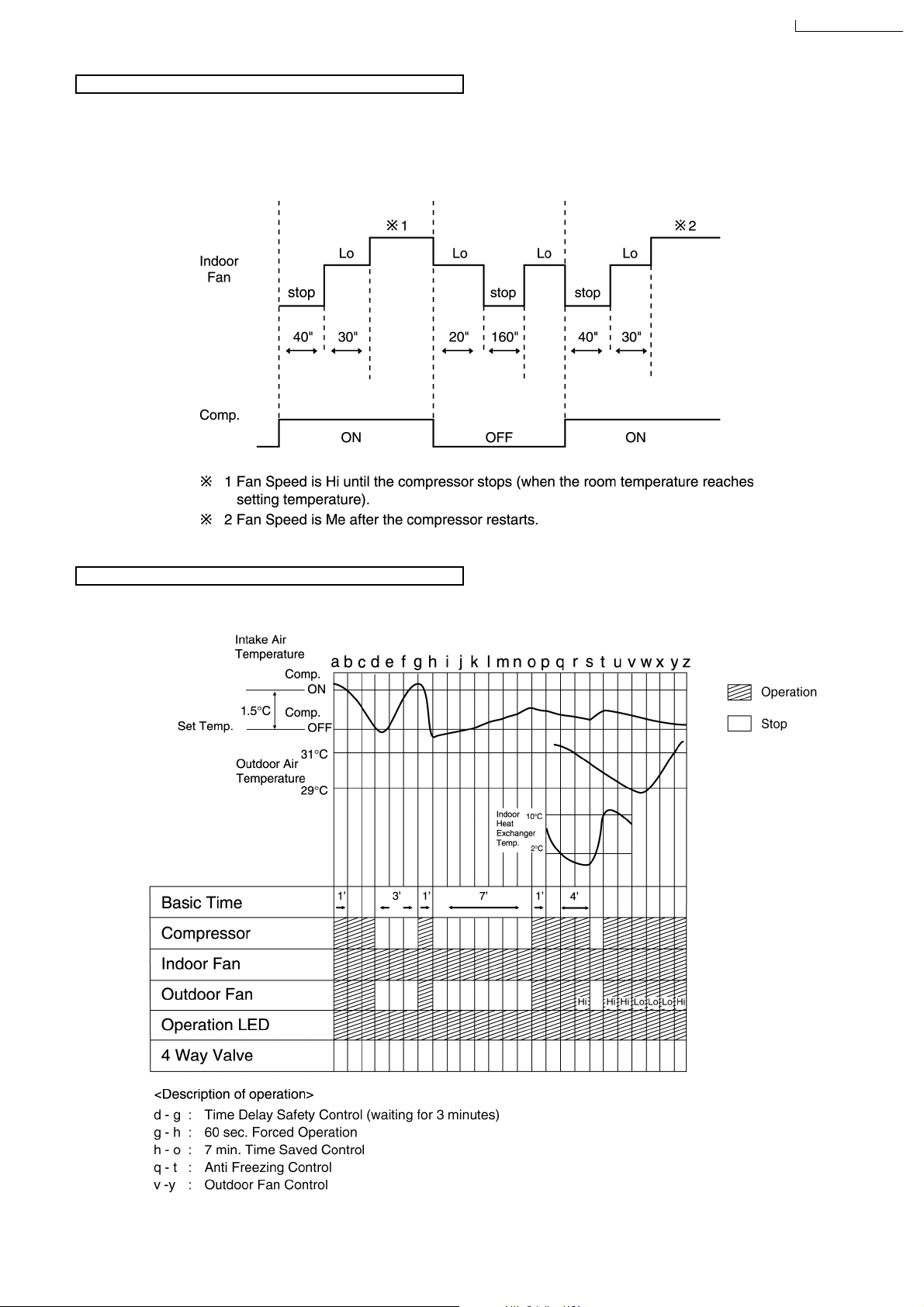
Time Delay Safety Control (3 minutes)
When the compressor is stopped by Power Switch, Remote Control or there is a power failure, it restarts after 3 minutes when
•
the Power Switch, Remote Control is turned ON or the power supply is resumed.
When the setting temperature is reached during cooling operation, the compressor stops and it will not start for 3 minutes.
•
7 minutes Time Saved Control
The compressor will start automatically if it has stopped for 7 minutes even if the room temperature is below the compressor
•
ON temperature.
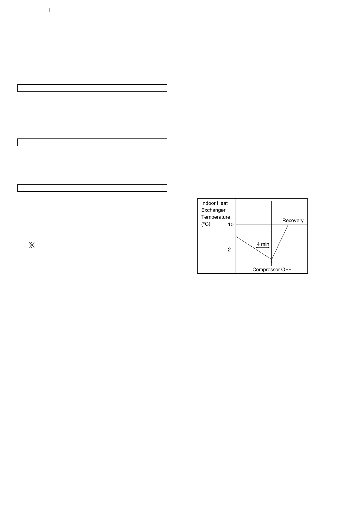
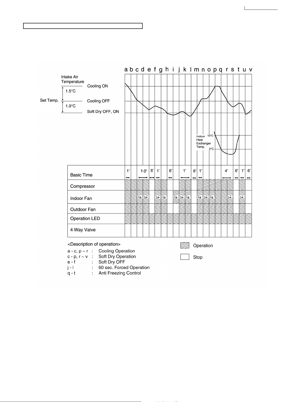
Anti-Freezing Control
If the temperature of the indoor heat exchanger falls
•
continuously below 2°C for 4 minutes, the compressor turns
off to protect the indoor heat exchanger from freezing. The
fan speed setting remains the same.
Compressor recommences when the indoor heat
•
exchanger temperature rises to 10°C (Recovery).
3 minutes waiting of Time Delay Safety Control is
valid for Cooling Operation.
12
Page 13
Automatic Fan Speed Mode
When Automatic Fan Speed is selected at Remote Control during cooling operation.
Fan speed rotates in the range of Hi to Me.
•
Deodorizing Control.
•
CS-A28BKP5/CU-A28BKP5
Cooling Operation Time Diagram
13
Page 14
CS-A28BKP5/CU-A28BKP5
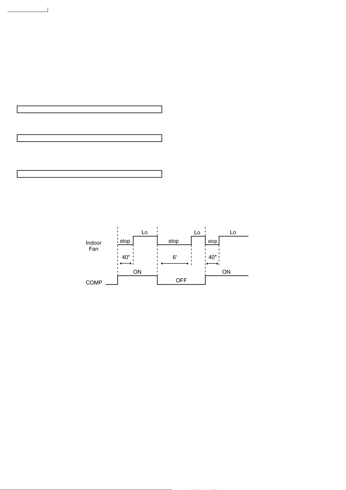
8.2. Soft Dry Mode Operation
The unit starts cooling operation until the room temperature reaches the setting temperature set on the Remote Control, and
•
then Soft Dry operation will start.
During Soft Dry operation, the Indoor Fan operates with Lo speed.
•
Once room temperature reaches below Soft Dry OFF temperature, Indoor Fan, Compressor and Outdoor Fan Stop for 6
•
minutes.
Time Delay Safety Control
Once the compressor stops, it will not start for 3 minutes during Cooling operation.
•
Anti-Freezing Control
Same as Anti-Freezing Control for Cooling Mode operation. (For Soft Dry region, 6 minutes waiting is valid during compressor
•
stops.)
Automatic Fan Speed Mode
When Automatic Fan Speed is selected at Remote Control during Soft Dry operation.
Fan speed rotates at Lo speed.
•
Deodorizing Control.
•
14
Page 15
Soft Dry Operation Time Diagram
CS-A28BKP5/CU-A28BKP5
15
Page 16
CS-A28BKP5/CU-A28BKP5
8.3. Heating Mode Operation
Heating in operation according to Remote Control setting.
•
Time Delay Safety Control
When the compressor is stopped by Power Switch, Remote Control or there is a power failure, it restarts after 3 minutes when
•
the Power Switch, Remote Control is turned ON or the power supply is resumed.
When the setting temperature is reached during heating operation, the compressor stops and it will not start for 4 minutes.
•
30 minutes Time Saved Control
The compressor will start automatically if it has stopped for 30 minutes even if the room temperature is below the compre ssor
•
OFF temperature.
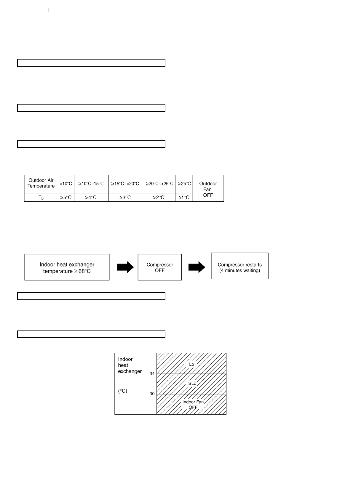
Overload Protection Control
If the temperature of the Outdoor Heat Exchanger less than -3°C, Outdoor Fan is ON. The Outdoor Fan stop, when Outdoor
•
Heat Exchanger temperature is T
or more according to Outdoor Air Temperature region as table below:
b
During starting of Heating mode and after deice, Outdoor Fan ON for 90 sec. (Hi).
If the Indoor heat exchanger becomes 68°C or more, the compressor will stop and restart automatically.
•
(Time Delay Safety Control - 4 minutes waiting)
4-way Valve Control
4-way valve ON during Heating operation, except deicing operation.
•
When the unit is switched to “OFF” during Heating operation, 4-way valve stay at Heating position for 5 minutes.
•
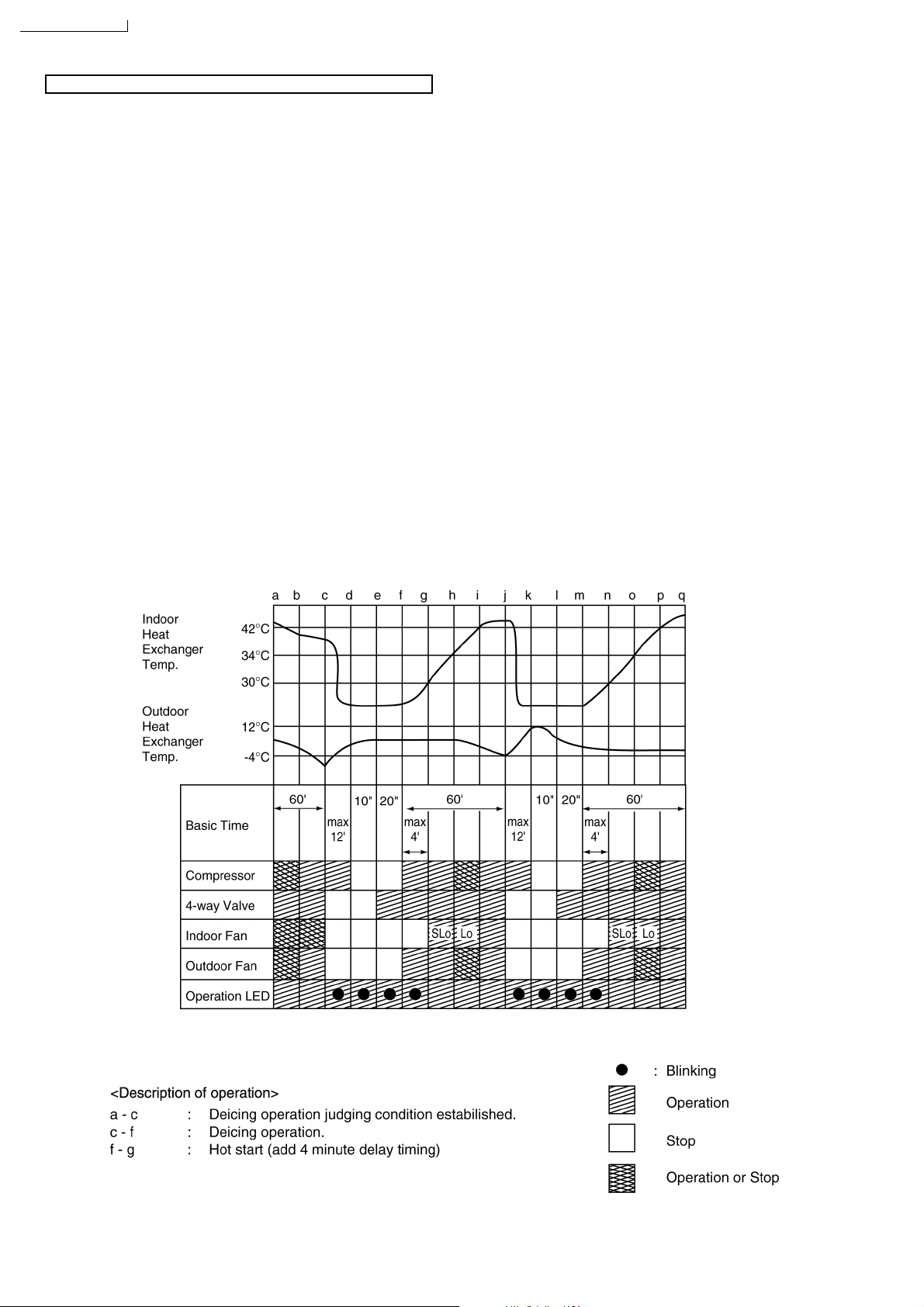
Hot Start Control
When Heating operation starts, Indoor Fan will not start until the indoor heat exchanger reaches 30°C as diagram shown.
Hot Start is completed when indoor heat exchanger reaches
42°C.
Maximum Hot start duration = 4 minutes. After 4 minutes, Hot
start operation will be shifted to normal Heating operation.
16
Page 17
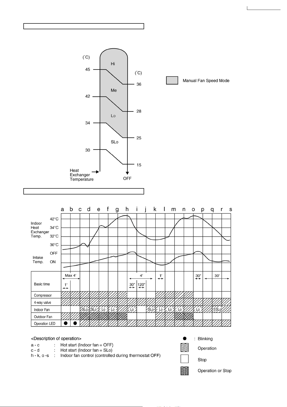
Automatic Fan Speed Mode
When Automatic Fan Speed is selected at Remote Control during heating operation.
Fan speed rotates in the range of Hi→SLo according to the heat exchanger temperature.
•
CS-A28BKP5/CU-A28BKP5
Heating Operating Time Diagram
17
Page 18
CS-A28BKP5/CU-A28BKP5
Deicing Control
Deice starts to prevent frosting at outdoor heat exchanger.
Normal Deicing
•
Deice operations detection commences in Heating operation starts or 60 minutes after previous deice operation. If the
outdoor piping temperature drops to -4°C for 50 sec. continuously during compressor is in operation, deice will start.
(There is no detection during Outdoor Fan stops.)
Overload Deicing
•
During heating operation, if the outdoor Fan OFF duration (due to overload control) is accumulated up to 60 minutes and
after compressor starts for 1 minute, deicing starts.
Deicing ends when
•
(a) 12 minutes after deicing operation starts;
(b) The outdoor piping temperature rises to about 12°C.
After deicing operation, compressor stops for 30 seconds and 4-way valve stays at cooling position for 10 seconds.
•
a) Normal Deicing Time Diagram
18
Page 19
CS-A28BKP5/CU-A28BKP5
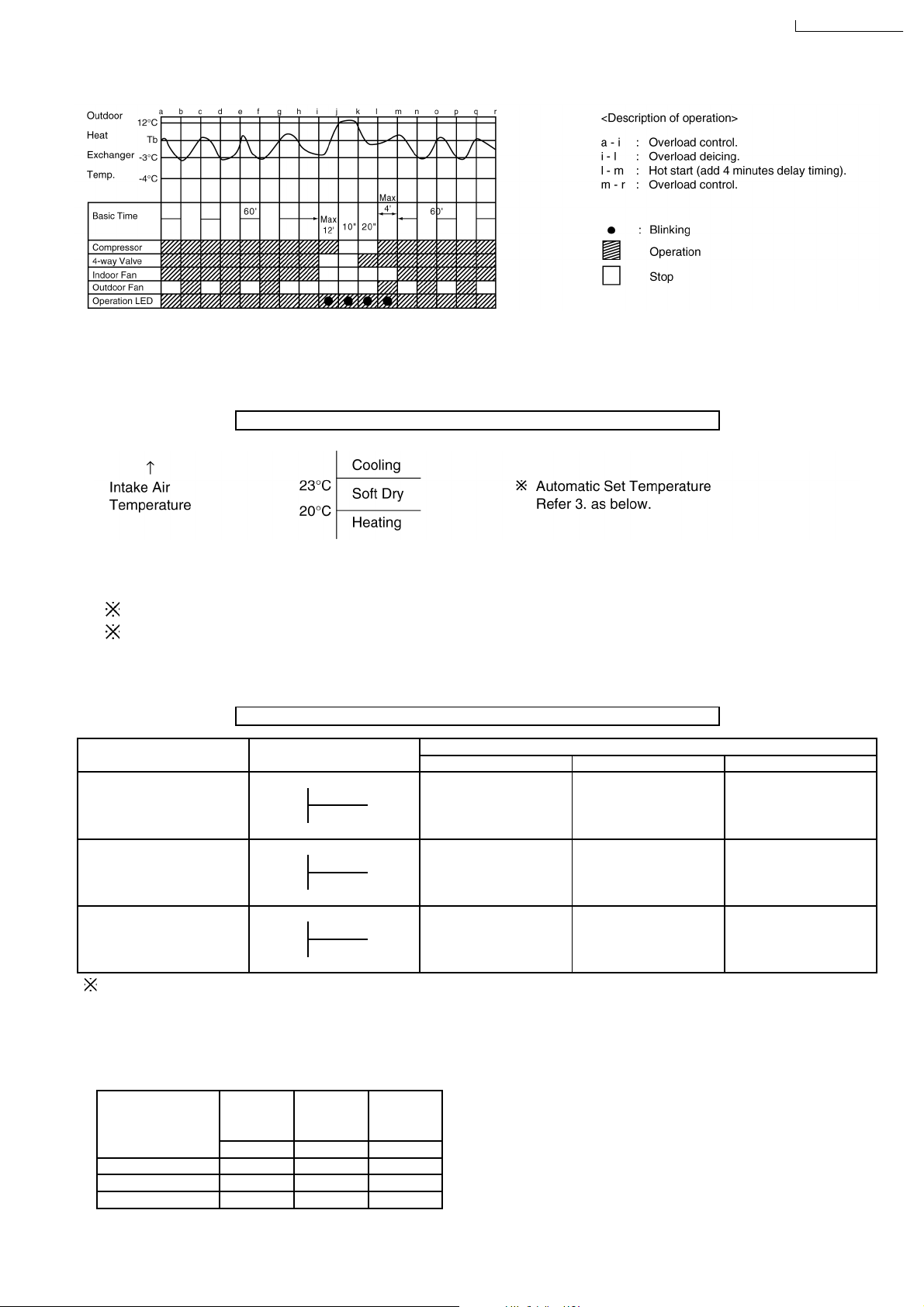
b) Overload Deicing Time Diagram
8.4. Automatic Mode Operation
1. When the Automatic Mode Operation is selected, the indoor fan operates at SLo fan speed for 20 seconds to sense intake air
temperature and determine the 1st operation mode.
Standard for Determining Operation Mode 1st Judgement
2. Operation mode will be determine again after 1 hour of operation, if the room temperature reaches to set temperature and
compressor off time is over 7 minutes 30 seconds continuously.
Indoor intake air is less than 16°C, Heating mode will immediate operate. (only in the first time judgement)
The present operation mode will be continued, if the room temperature does not reach to set temperature (Compressor
keeps running) eventhough after 1 hour from automatic operation mode started.
For 2nd judgement onwards, indoor fan will operate for 20 seconds to sense the intake air temperature for determining
operation mode.
Standard for Determining Operation Mode 2nd Judgement onwards
Present Judgement Next Mode
Mode Cooling Soft Dry Heating
O O
Cooling 23°C Cooling (Judgement: Not Applicable (Judgement:
Heating 23°C & Above) Below 23°C)
O O
Soft Dry 20°C Soft Dry Not Applicable (Judgement: (Judgement:
Heating 20°C & Above) Below 20°C)
O O
Heating Cooling (Judgement: Not Applicable (Judgement:
25°C Heating 25°C & Above) Below 25°C)
Automatic Set Temperature Refer 3. as below.
3. Automatic Set Temperature
For each operation, set temperature will automatically set as shown below.
However it can be selected 2°C higher or 2°C lower from standard set temperature by pressing the “Room Temperature Setting
button”.
Operation Higher Standard Lower
Mode
(+2°C) (±0°C) (-2°C)
Cooling 27°C 25°C 23°C
Soft Dry 24°C 22°C 20°C
Heating 23°C 21°C 19°C
19
Page 20
CS-A28BKP5/CU-A28BKP5
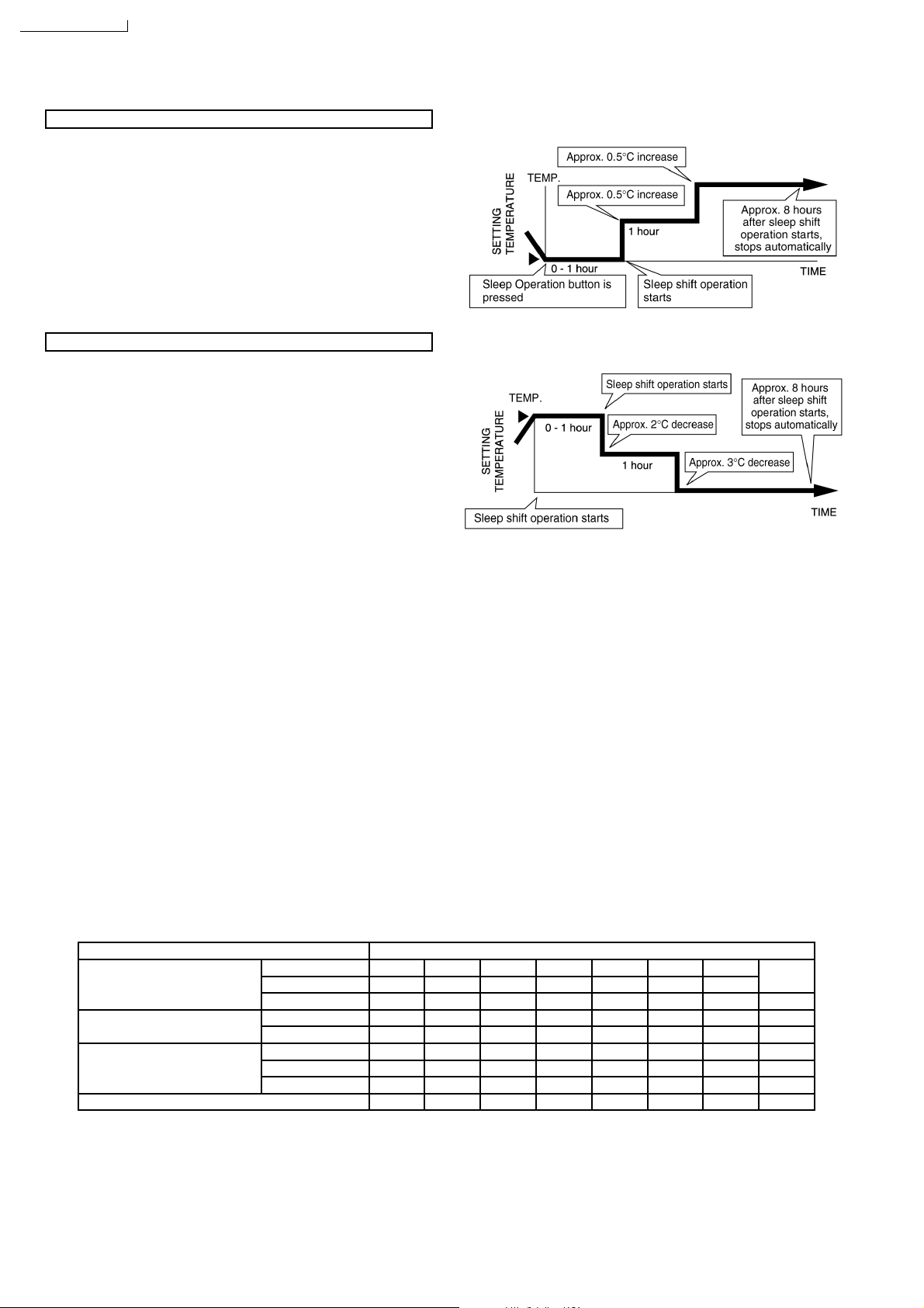
8.5. Sleep Mode Auto Operation
Cooling or Soft Dry Operation
When you press the SLEEP Mode, the following movement will
start to avoid overcooling.
The fan speed refer to Indoor Fan Motor Control.
•
The setting temperature will be risen by
•
operation and by
The operation will stop after8hours.
•
When using together with the Timer, the ON-Timer has
•
0.5
°C one hour later.
priority.
Heating Operation
When you press the SLEEP Mode, the following movement will
start to avoid overheating.
The fan speed refer to Indoor Fan Motor Control.
•
The setting temperature will be descented by 2°C at the start
•
of operation and by 3°C one hour later.
The operation will stop after8hours.
•
When using together with the Timer, the ON-Timer has
•
priority.
0.5
°C at the start of
8.6. Auto Restart Control
If there is a power failure, operation will be automatically restarted when the power is resumed.
•
It will start with previous operation mode and airflow direction.
(Time Delay Safety Control is valid)
Auto Restart Control is not available when Timer or Sleep Mode is set.
•
This control can be omitted by cutting the jumper wire J2. (Refer Circuit Diagram)
•
8.7. Indoor Fan Speed Control
Auto Fan Speed Control
•
When set to Auto Fan Speed, the fan speed is adjusted between maximum and minimum setting as shown in the table.
Manual Fan Speed Control
•
Basic fan speed adjustment (3 settings, from Lo to Hi) can be carried out by using the Fan Speed selection button.
Fan Speed High Speed
Manual O O O
Cooling Auto O O O O
Sleep O
Soft Dry Manual, Auto O
Sleep O
Manual O O O
Heating Auto O O O O O O
Sleep O O O
Hi Me Lo SLo SSLo STOP
O
←→
Low Speed
20
Page 21
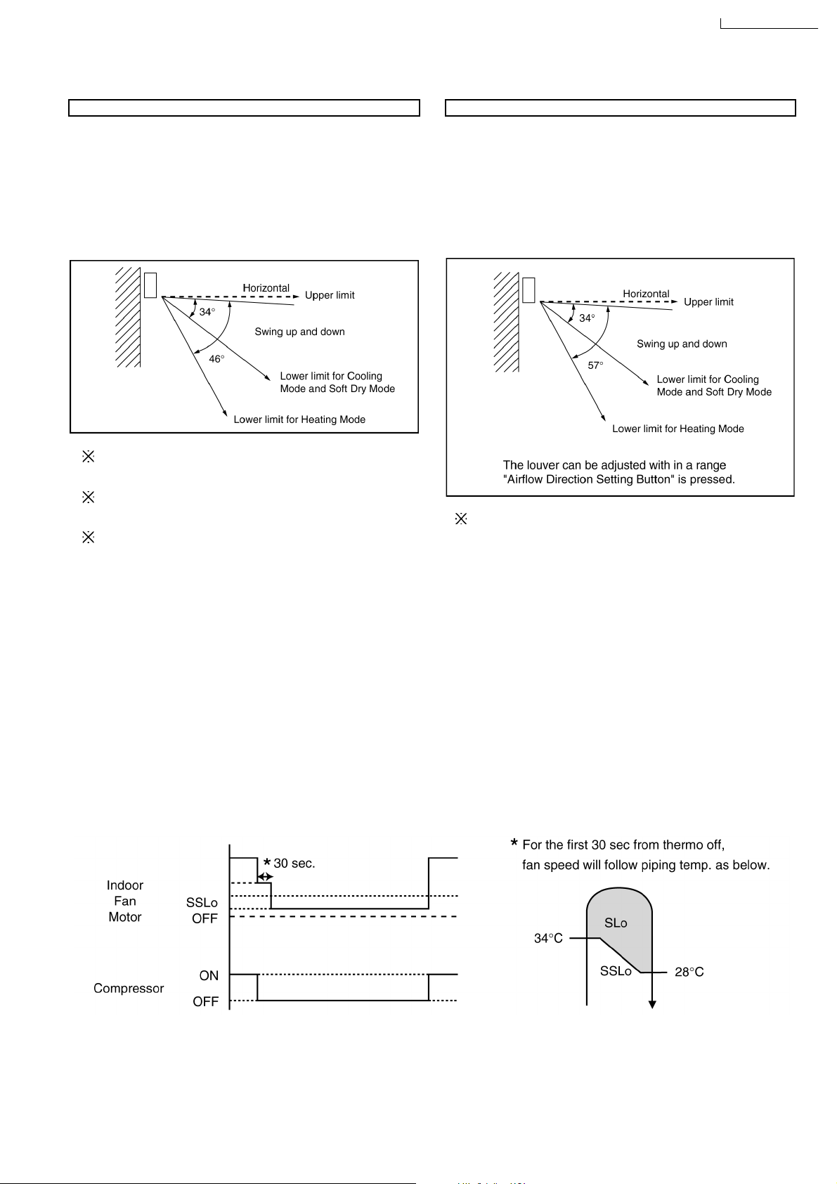
8.8. Airflow Direction Control
CS-A28BKP5/CU-A28BKP5
Airflow Direction Auto-Control
When set a Airflow Direction Auto-Control with remote
•
control, the louver swings up and down as shown in the
diagram.
The louver does not swing when the Indoor Fan stops
•
during operation.
When stopped with remote control, the discharge vent is
•
closed with the louver.
The left and right airflow direction louvers can be adjusted
manually.
1 There is no swinging while indoor fan is stopped during
Cooling and Soft Dry operation.
2 In Heating operation, when the indoor heat exchanger
temperature rises to 38°C, the airflow direction is changed
from upper limit to lower limit. When the indoor heat
exchanger temperature falls to 35°C, the air flow direction
is changed from lower limit to upper limit.
Airflow Direction Manual Control
When the airflow direction set button is pressed, the
•
automatic airflow is released and the airflow direction louver
move up and down in the range shown in the diagram.
The louver can be stopped by releasing the button at the
desired louver position.
When the remote control is used to stop the operation, the
•
discharge vent is closed with airflow direction louver.
The left and right airflow direction louvers can be adjusted
manually.
8.9. Delay ON Timer Control
When the Delayed ON Timer is set by using the remote control, the unit will start operate slightly before the set time, so that
•
the room will reach nearly to the set temperature by the desired time.
For Cooling and Soft Dry mode, the operation will start 15 minutes before the set time.
•
For Heating mode, the operation will start 30 minutes before the set time.
•
For Automatic mode, the indoor fan will operate at SLo speed for 20 seconds, 30 minutes before the set time to detect the
•
intake air temperature to determine the operation mode. The operation indication lamp will blink at this time.
8.10. Cold Draught Control
When COMP = Thermal OFF, indoor fan speed immediately changed to SLo for 30 sec., followed by SSLo speed until COMP
•
= ON.
During cold draft c/m operation, fan speed will be SSLo only.
SSLo: Fan will be running at Lo speed with SSR ON for 0.6 sec. and OFF for 5.0 sec.
21
Page 22
CS-A28BKP5/CU-A28BKP5
9 Operating Instructions
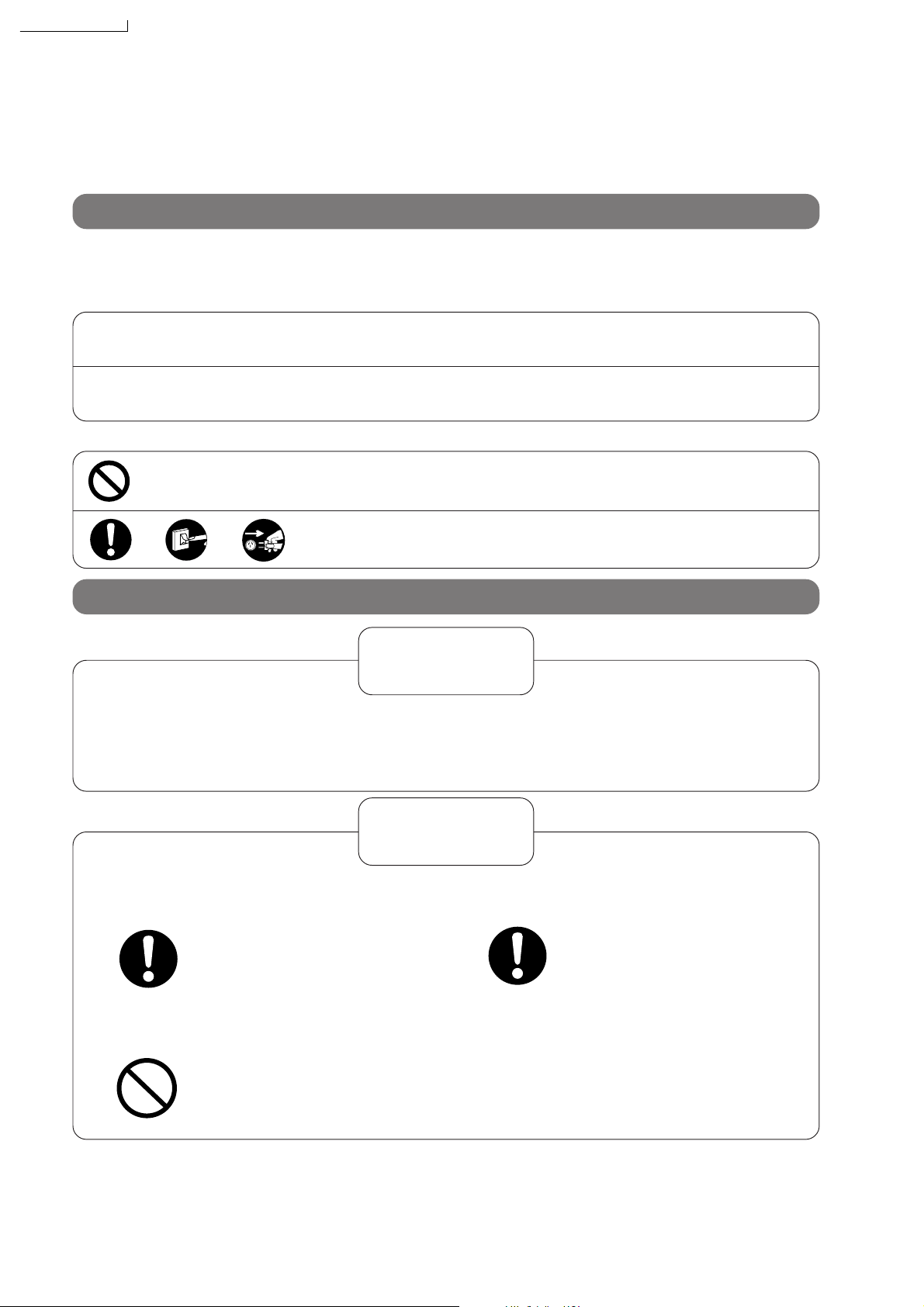
Safety Precautions
Before operating, please read the following “Safety Precautions” carefully.
To prevent personal injury, injury to others and property damage, the following instructions must be followed.
■ Incorrect operation due to ignoring of instructions will cause harm or damage, the seriousness of which is
classified as follows :
Warning
:
This sign warns of death or serious injury.
!
!
■ The instructions to be followed are classified by the following symbols :
Caution
OFF
This sign warns of injury or damage to property only.
:
This symbol (with a white background) denotes an action that is
PROHIBITED.
These symbols (with a black background) denote an action that is
COMPULSORY.
Installation precautions
Warning
!
■ Do not install, remove and reinstall the unit yourself.
Improper installation will cause leakage, electric shock or fire. Please consult an authorized dealer or
specialist for the installation work.
!
■ This room air conditioner must be
earthed.
Improper grounding could cause
electric shock.
■ Do not install the unit in a place where
there may be explosive gas leaks.
Gas leaks near the unit could
cause fires.
Caution
■ Ensure that drainage piping is connected
properly.
Otherwise, water will leak out.
22
Page 23
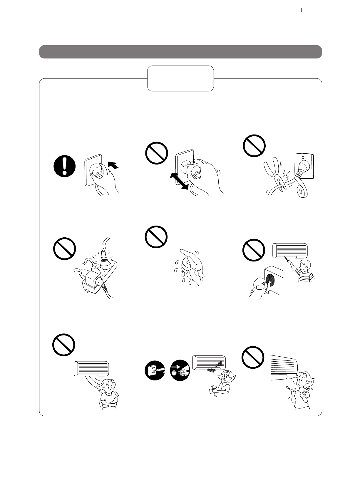
Operation precautions
Warning
!
CS-A28BKP5/CU-A28BKP5
■ Insert the power plug
properly.
Heat generated by a loose
power plug could cause electric
shock or fire.
Electrical outlet and power plug
shall be easily accessible.
■ Do not modify the length of
the power cord or use an
extension cord.
It could cause electric shock or
fire.
■ Do not operate or stop the
unit by inserting or pulling
out the power plug.
It could cause electric shock or
fire.
■ Do not operate the unit with
wet hands.
It could cause an electric shock.
■ Do not damage or use an
unspecified power cord.
It will cause electrical shock or
fire.
■ Do not insert finger, sticks
or other objects into the
units.
It could lead to physical injury
and cause damage to the units.
■ Do not be directly exposed
to the cold airstream for
too long.
It could lead to health problems.
■
If there is a smell of burning,
stop the air conditioner and
disconnect the power supply.
The heat generated could cause
electric shock or fire. Please consult an authorized dealer or service centre.
F
F
O
Switch off
the breaker.
Disconnect
the power
plug.
23
■ Do not try to repair the unit
yourself.
It could lead to fire or cause an
electric shock. Please call an
authorized dealer or service
centre.
Page 24
CS-A28BKP5/CU-A28BKP5
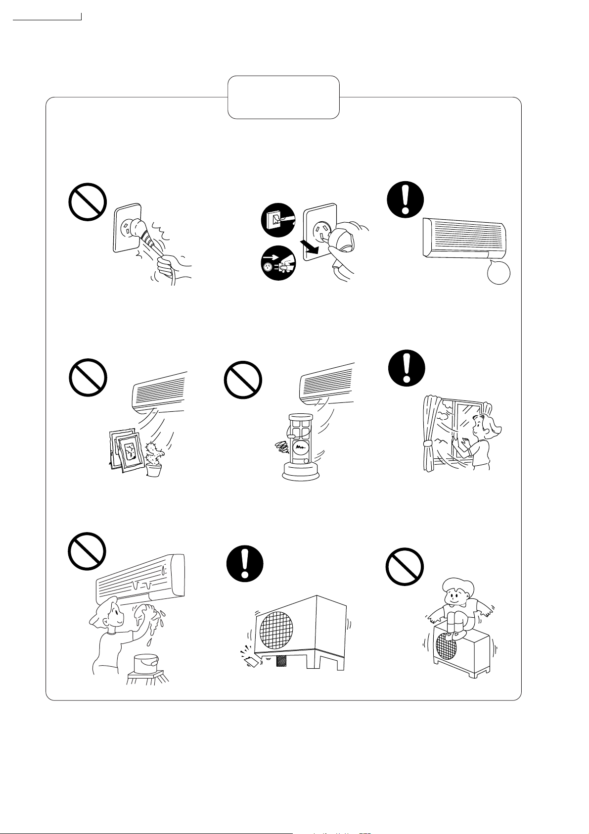
Caution
!
■ Do not remove the power
plug by pulling the cord.
Hold the plug when disconnecting the plug from the wall outlet.
■ Do not use for other pur-
poses.
Do not use for preservation purposes. It will affect food quality,
animals or plants.
■
Switch off the power supply if
the unit is not going to be
used for a long period of time.
If dust accumulates on the plug, it
will generate heat and this could
cause a fire.
Switch off
the breaker.
Disconnect
the power
plug.
OFF
■ Do not place combustor in
the path of the airflow from
the unit.
Incomplete combustion could
cause toxic gas (CO) poisoning.
■ When cleaning the unit, re-
move the plug.
This is to prevent injury due to
the rotating fan in the unit.
OFF
■
Ventilate the room regularly.
If not ventilated regularly, the
lack of oxygen could cause
headaches.
■ Do not wash the unit with
water.
It could cause an electric shock.
■ Inspect the unit for any
damage.
Ensure that the necessary repairs
are carried out.
■ Do not sit or place any-
thing on the outdoor unit.
You might fall off or the unit
might collapse.
24
Page 25

Name of Each Part
CS-A28BKP5/CU-A28BKP5
Indoor unit
Air Intake Vent
Panel Opener
Vertical Airflow
Direction Louver
Air Outlet Vent
Front Panel
Signal Receptor
Power Sleep Timer
Red Orange Orange
Operation Indication
Lamps (LED)
Airflow Direction Louver
Horizontal
(Manually adjusted)
Outdoor unit
Air Intake Vents
Air Outlet Vents
(Side)
(Rear)
Ground Terminal
(Inside Cover)
Piping
Drain Hose
25
Page 26

CS-A28BKP5/CU-A28BKP5
Remote control
Signal Transmitter
Operation Display
Accessories
Remote Control Two R03 dry-cell
DRY
AUTO FAN
h j k
ER
COOLHEAT
ON-TIM
°C
m n o
N
R
E
/O
AM
M
I
F
T
-
F
F
F
AUTO
O
O
c
P
E
FAN SPEED
PM
E
L
S
ANUAL
P.
M
TEM
ODE
ING
M
AIR SW
ING
SW
batteries or equivalent
Air Purifying Filters
(with deodorizing function)
Sleep Mode
Operation Button
AUTO
c
HEAT
COOL
m n o
DRY
AUTO FAN
°C
ER
OFF-TIM
PM
j
h
SLEEP
OFF/ON Button
k
ER
N-TIM
O
AM
OFF/ON
TEMP.
MODE
SWING
Airflow Volume
Selection Button
FAN SPEED
MANUAL
AIR SWING
Airflow Direction Manual
Control Button
Room Temperature
Setting Button
Operation Mode
Selection Button
Airflow Direction Auto Control Button
Separate displays and functions are available when the door is opened.
ON-Timer Button
Door
OFF-Timer Button
Time
Button
Door
OFF-TIMER ON-TIMER
CANCEL SET
q
Cancellation Button
Clock Button
26
TIME
Set Button
Page 27

Preparation Before Operation
Before operating the unit
CS-A28BKP5/CU-A28BKP5
1
■ Connect the power
supply cord to an
independent power
supply.
23
■ Open the front panel.
Hold the panel openers at both
sides and pull up the front panel.
<Note>
Use under the following conditions :
■ Remove air filter.
Air
filter
Hold the tab to raise up
slightly and then pull down.
■ Insert air purifying filter.
Insert the air filters.
Be careful not to
hurt your hands by
metal parts.
Air purifying
filter
(Unit in °C)
DBT : Dry Bulb Temperature
WBT : Wet Bulb Temperature
Maximum Temperature
Minimum T emper ature
Cooling
Indoor Outdoor
DBT WBT DBT WBT
32 23 43 26
16 11 16 11
27
Heating
Indoor Outdoor
DBT WBT DBT WBT
30
16
_
_
24 18
-5
-6
Page 28

12
CS-A28BKP5/CU-A28BKP5
How to insert batteries
Gently press the
OPEN
place marked
[OPEN] and slide
the cover toward
you.
Make sure that the
signal path is
obstructed.
r
e
O
P
E
N
e
(Two R03 dry-cell
batteries or equivalent)
Operating the remote control
not
r
■ Fix the cover to the back of the remote
control (“PM 12:00” will flash in the operation display.)
er Be sure
that the (+) and
(–) directions
are correct.
PM
12
:
00
If the display does not appear when the batteries
are inserted, remove the batteries and
insert them once more.
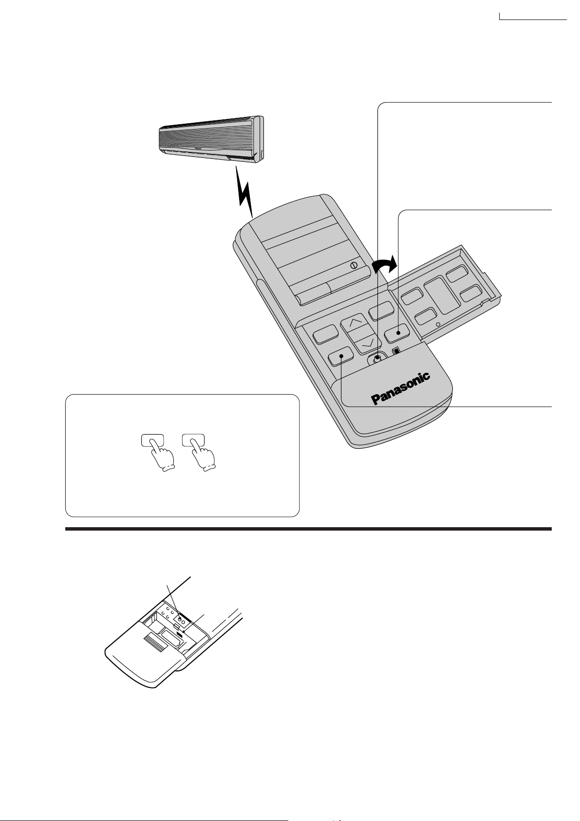
■ Aim at the signal receptor on the room air conditioner when operating.
■ Do not drop or throw the remote control.
■ Do not place the remote control in a location that
is exposed to direct sunlight or next to a heating
unit or other heat source.
The maximum distance at which signals
can be received is
about 10 m.
Pull out the power plug or turn off the
power breaker when:
■ The air conditioner is not going to be used
for an extended period of time.
If the power switch is left at “I” (ON), approximately
3.25 watts of electric power are used even if the
main unit is turned off by remote control.
■ There is a danger of lightning.
The air conditioner is provided with a built-in protec-
tive device, but the control equipment may be adversely affected depending on the extent of lightning activity.
■ Signal received sound:
One short beep or one long beep.
Regarding the batteries.
■
The batteries can be used for approximately one
year.
■
Do not use rechargeable (Ni-Cd) batteries,
because such batteries differ from standard
dry-cell batteries in shape, dimensions and
performance.
■
Be sure to replace the batteries with two new
batteries of the same type.
■
Do not dispose of empty batteries in household
waste. Take them to special local collection sites.
28
Page 29

How to Operate
Auto Restart Control.
■ If there is a power failure, operation will be
automatically restarted after 3 minutes when
the power is resumed with previous operation
mode and airflow direction.
(When the operation is not stopped by remote control.)
■ If you do not intend to continue the operation
when the power is resumed, pull out the
power plug at main unit or power supply.
When you switch on the power switch, the
operation will be automatically restarted
with previous operation mode and airflow
direction.
Note: 1. If you do not require Auto Restart
Control, please consult your dealer.
2. Auto Restart Control is not available
when Timer or Sleep Mode is set.
AUTO
m
AUTO FAN
SLEEP
OFF/ON
MODE
TEMP.
SWING
CS-A28BKP5/CU-A28BKP5
FAN SPEED
MANUAL
AIR SWING
Recommended temperature for health
and comfort.
For Heating : 20°C – 24°C
For Cooling : 26°C – 28°C
For Soft Dry : 1°C – 02°C lower than
room temperature.
<Operation Details>
AUTO – Automatic Operation.
■ Once the Automatic Operation is selected, the
indoor temperature sensor operates automatically to select the desired operation mode with
Cooling, Soft Dry or Heating.
■ The operation mode changes every hour,
when necessary.
DRY – Soft Dry Operation.
■ Soft Dry is a very gentle Cooling Operation
consisting primarily of dehumidifying. It does
not lower the room temperature very much.
Cooling Operation
until room temperature reach
the setting tem
ature
Setting
Temperature
When room temperature reaches the setting temperature, operation will switch to Soft Dry.
per-
es
Super Low airflow amount
29
Page 30
CS-A28BKP5/CU-A28BKP5
1
2
3
4
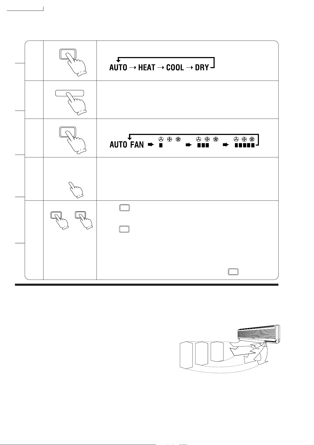
MODE
OFF/ON I
FAN SPEED
TEMP.
i
Press to select operation mode.
■ The display changes in the order
each time the button is pressed.
Press to start the operation.
■ Operation indication lamp (RED) will light up.
■ Press once more, to stop the operation.
Press to select airflow volume.
■ The display changes in the order.
Automatic Low Medium High
Press to select room temperature.
■ Heating, Cooling, Soft Dry – Select temperature as desired.
(16°C ~ 30°C)
■ Automatic.
▼
m n
2°C lower than
standard
n
standard
▼
n o
2°C higher than
standard
SWING
MANUAL
5
HEAT – Heating Operation
■ Defrosting Operation
Depend on the outdoor temperature, the operation occasionally stops to melt the frost on the
outdoor unit.
■ Heat is obtained from outdoor air to warm up the
room. When the outdoor ambient air temperature
falls, the heating capacity of the unit might be
reduced.
We recommend that you use an additional heating device when the outdoor ambient air temperature is low.
Press continuously.
■ The vertical airflow direction louver will move up and down. Release the
Press .
■
MANUAL
button when the louver is at the desired position.
SWING
Cooling & Soft Dry – The vertical airflow direction louver will swing up and
Heating – When the discharge air temperature is low such as at the start of
heating operation, the cold air blows at horizontal level.
As the temperature rises, the hot air blows in a downwards
direction.
To stop the automatic airflow direction operation, press button.
down automatically.
MANUAL
Automatic Airflow Volume
■ The speed of the indoor fan is adjusted automatically according to the operation. The indoor fan
stops occasionally during cooling operation.
Range of louver adjustment
34°
46°
(Airflow
Heating
Heating
Direction Manual)
(Airflow
Cooling/Soft Dry
(Airflow Direction
Manual and Auto)
Direction Auto)
57°
30
Page 31
Setting the Timer
PM
11:30
SLEEP
CS-A28BKP5/CU-A28BKP5
OFF/ON
If there is a power failure.
To reset the Timer.
(Example) If the OFF Timer has been set.
OFF-TIMER
SET
➡
■ Even if there is a power failure, the setting time
is still stored in the memory because the remote control is a battery operated type.
<Note>
Regarding remote control.
[RESET] points
[B ↔ A] switch
ON-TIMER
OFF-TIMER TIME
CANCEL
q
SET
■ If the current time is not set correctly, correct
Timer setting will not be possible.
■ When the Timer is set, the current time display
will vanish.
OPEN
■ [RESET] points will clear the memory once
they are shorted.
■ [B ↔ A] switch is used when two air
conditioners units have been installed in one
room. Please consult your dealer.
31
Page 32

q
q
CS-A28BKP5/CU-A28BKP5
To set the current time.
■ Set hours and minutes
To set the Timer.
■ OFF Timer Set hours and minutes
The “
■ ON Timer Set hours and minutes
The “
To cancel the Timer.
■ OFF Timer
OFF-TIMER
OFF-TIMER
” will blink.
0N-TIMER
ON-TIMER
” will blink.
OFF-TIMER
TIME
TIME
TIME
CANCEL
.... to advance the time
.... to reverse the time
.... to increase 10 minutes
each step.
.
... to decrease 10 minutes
each step.
.... to increase 10 minutes
each step.
.
... to decrease 10 minutes
each step.
SET
The Timer indication lamp at main
unit will light up. LED colour: Orange.
SET
The Timer indication lamp at main
unit will light up. LED colour: Orange.
● The Timer indication lamp at
main unit will go off.
● To cancel the ON Timer, follow
the same procedure.
To change the Timer setting time.
■ (Example) To change the ON Timer setting time.
0N-TIMER
Change hours and minutes setting
TIME
Timer
■ The ON Timer and OFF Timer can only be
set once during a day.
■ The operation will start before the actual
setting time with ON Timer setting.
Cooling and Soft Dry : 15 minutes before
Heating and Automatic: 30 minutes before
This is to allow time to attain your desired
set temperature.
.
... to increase 10 minutes
each step.
.
... to decrease 10 minutes
each step.
■ Setting the OFF Timer.
This is useful for saving electricity costs in-
curred by forgetting to turn off the air conditioner.
■ Setting the ON Timer.
If the air conditioner is set before you go out,
the room temperature will be close to your
desired temperature when you return.
SET
32
Page 33

Convenient Operation
Sleep Mode
This is to gain a comfortable room temperature while sleeping.
CS-A28BKP5/CU-A28BKP5
To set Sleep Mode.
■ Press
SLEEP
(The sleep indication lamp on the
main unit will light up.)
k
j
h
°C
c
27
PM
11:30
SLEEP
OFF/ON
TEMP.
FAN SPEED
MANUAL
AUTO
MODE
SWING
AIR SWING
<Information>
■ Cooling or Soft Dry Operation for Sleep Mode
movement will start to avoid overcooling.
Approx. 0.5°C increase
TEMP.
Approx. 0.5°C increase
Approx. 8 hours after sleep
shift operation starts, stops
automatically
SETTING
TEMPERATURE
Sleep Operation button is pressed
0 – 1 hour
1 hour
Sleep shift operation
starts
TIME
To cancel Sleep Mode.
■ Press once more
SLEEP
(The sleep indication lamp on the
main unit will switch off.)
Sleep Mode Operation.
■ When the room temperature reaches
the setting temperature or after 1
hour of operation, sleep shift
operation starts and the airflow
volume will automatically change to
low.
■ Sleep Mode Operation time is 8
hours.
■ When using together with the Timer,
the Timer has priority.
■ Heating Operation for Sleep Mode movement will start to avoid overheating.
TEMP.
0 – 1 hour
SETTING
TEMPERATURE
Sleep Operation button is pressed
Sleep shift operation starts
Approx. 2°C decrease
1 hour
Approx. 3°C decrease
Approx. 8 hours
after sleep shift
operation starts,
stops
automatically
TIME
33
Page 34
CS-A28BKP5/CU-A28BKP5
When the remote control cannot be used
Test Run Button.
(Use when installing and moving)
Auto Operation Button.
■ When the remote control cannot be
used, press Auto Operation Button to run
Automatic Operation.
(Airflow direction setting will be automatic.)
■ Press Auto Operation Button.
(The operation indication lamp will blink for 20
seconds, and then light up)
● If the button is pressed once more, the
air conditioner will stop.
(The operation indication lamp will switch
off.)
OFF/ON remote control signal receiving sound
AUTO
OFF/ON
■ The Remote Control Signal receiving sound can be omitted as desired.
■ To switch OFF the signal receiving sound, press Auto Operation Button for 10 seconds or more. At
the same time, Automatic Operation starts.
(To switch ON, press Auto Operation Button once more for 10 seconds or more.)
34
Page 35

Operation Hints
CS-A28BKP5/CU-A28BKP5
Adjust room temperature properly. Set the
■
temperature 1°C higher (Cooling Operation)
or 2°C lower (Heating Operation) than actu
ally desired. Approximately 10% of electricity
costs can be saved.
1°C higher
2°C lower
Clean the air filter regularly. Blockage in the
■
air filter reduces the airflow and lowers the
cooling or heating. Clean at least once every
2 weeks. Otherwise, about 6% of electricity
cost will be wasted.
Prevent wastage with the Timer. Use Timer
■
when sleeping or going out to save electricity
cost.
Do not block the air outlet vents at outdoor
■
unit. Otherwise, it will lower the cooling or
heating performance.
35
Page 36

CS-A28BKP5/CU-A28BKP5
Make sure that the doors and windows are
■
shut. Otherwise, cooling and heating per
formance will be reduced and electricity cost
is wasted.
Proper airflow direction adjustment. Set the
■
airflow direction louvers horizontal for Cool
ing Operation and downwards for Heating
Operation. Operation result will be better.
Keep blinds or curtains closed. Do not let sun
■
shine enter the room directly. About 5% of
electricity cost can be saved.
Use insulating material for better
■
performance. Use insulating material during
construction or renovations. It will save
electricity cost.
Cooling
Heating
36
Page 37

CS-A28BKP5/CU-A28BKP5
Better Care and Maintenance
Regular care and maintenance will extend the life of the air conditioner and prevent wastage of electricity.
Before performing any maintenance procedure, be sure to switch off the main power supply.
Caution
Do not use water or volatile liquids.
■ Do not make air conditioner wet, as there is the danger that it could cause
■ Using water above 40°C could cause deformation and/or discolouration.
■ Volatile liquids such as thinner or benzene may damage the air condi-
Cleaning the air conditioner and air filters
Once every 2 weeks is recommended.
■ Clean the air conditioner.
Wipe gently with a soft, dry cloth.
electric shocks.
Be sure not to apply water when cleaning or at any other time.
tioner.
■Clean the air filters.
■ To remove the dust adhering to the filters,
either use a vacuum cleaner, or wash them in
water and dry in the shade.
■ Re-insert the filters correctly at the left and right,
with the side marked [FRONT] facing forward.
■ Purchase replacement filters from your air conditioner dealer if the air filters become damage.
Air Filter No. CWD4209540 (right)
CWD4209550 (left)
37
Page 38

Replacement of air purifying filters
Remove the air filters.
2
Air filter
<Note>
■ Solar Refreshing Deodorizing Filter
• Used to remove unpleasant odour and deodorize the air in the room.
• Reusable.
• Vacuum, place under direct sunlight for 6 hours and fit it back in place.
(Recommended : every 6 months)
■ Catechin Air Purifying Filter
• The filter is coated with catechin to prevent growth of bacteria and viruses.
• Reusable.
• Vacuum and fit it back in place
(Recommended : every 6 months)
Remove the air purifying filters.
Catechin Air
Purifying Filter
Solar Refreshing
Deodorizing Filter
! Caution
Be careful not to
hurt your hands on
metal parts.
31
■ Recommended to change these filters every 3 years.
Do not reuse damaged filters.
Consult the nearest authorized dealer to purchase a new filter.
Catechin Air Purifying Filter No.: CZ-SF71P
Solar Refreshing Deodorizing Filter No.: CZ-SFD71P
If you operate the air conditioner with dirty filters:– Air is not purified
– Cooling capacity decreases
– Foul odour is emitted
Remove the filters
from the filter frame.
Filters
When not using the air conditioner for a long period
Operate the air conditioner for 2 to 3 hours.
■ Type of operation: Cooling.
1
■ Temperature setting: 30°C.
In order to dry out the
internal mechanisms
For air conditioners with
a power plug, stop operation by remote control and
2
pull out the power plug.
Note: If the unit is not off by
remote control, the unit
will operate when you
plug in (because
of Auto-restart
Control is provided).
Remove the batteries
from the remote control.
3
Pre-season inspection (The earlier the better)
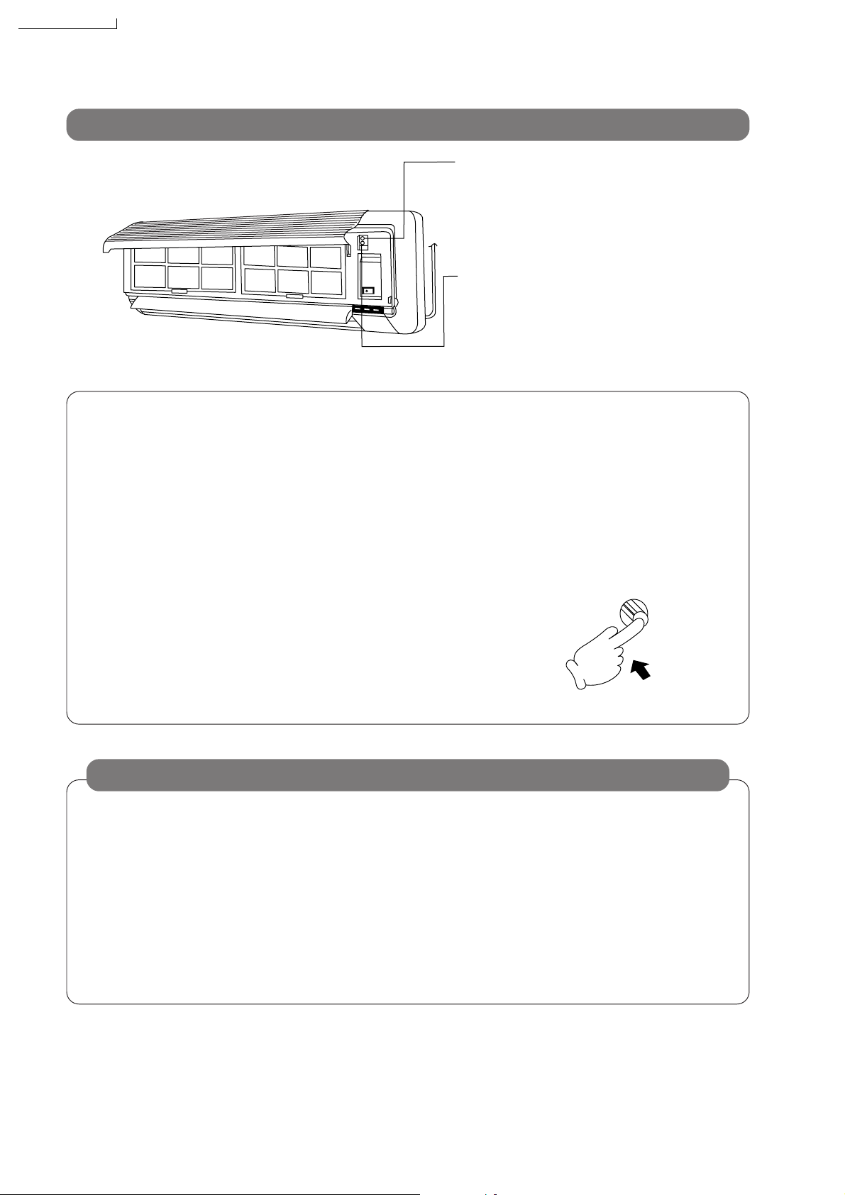
■ Is the discharge air
cold (warm)?
Operation is normal if, 15 minutes after the start of operation,
the temperature difference between the air intake vent and
outlet vent is 8°C or above for
cooling and 14°C or above for
heating.
Is cool (warm) air
coming out?
■ Are the air outlet
vents and air intake
vents obstructed?
If they are, cooling
performance will drop and
cause problems.
■ Is the drain hose
cracked or crushed?
If it is, leaks will
result.
38
■ Are the remote
control batteries in
good condition?
If display is faint or
no display is visible,
the batteries should
be replaced.
Page 39

Troubleshooting
Q
Is it okay?
Normal operation
A
This is the answer.
CS-A28BKP5/CU-A28BKP5
Sight
?
Air conditioner has been restarted, but does not
operate for 3 minutes.
During Soft Dry Mode
Operation, the air conditioner stops.
Airflow does not begin
immediately during Heating Operation.
The room has a peculiar
odour.
A sound like water flowing
can be heard. A noise that
sounds like the compressed air releasing into
atmosphere
This is to protect the air conditioner. Wait until
the air conditioner begins operating.
Soft Dry Mode Operation is a very gentle cooling
operation consisting primarily of dehumidifying.
The air conditioner may stop for approximately 6
minutes in order to prevent overcooling.
If the room temperature rises again, the operation will recommence.
If the airflow begins before its temperature become warm, it will cause an undesired cooling
effect. In order to prevent this, the airflow will not
begin until it is sufficiently warm.
(The operation lamp will blink until the airflow
begins.)
This may be a damp smell exuded by the walls,
carpet, furniture or clothing in the room.
This is the sound of refrigerant flowing inside the
air conditioner unit.
This is the sound of reversing the freon flow inside the unit at the starting and finishing the defrosting during Heating operation.
z
z
z
Stop for 12 minutes.
Blinks
It seems that fog is coming
out from the air
conditioner.
Operation stops for about
12 minutes during heating.
(The operation lamp
blinks.)
During Automatic Airflow
Volume setting, indoor fan
stops occasionally.
Condensation occurs when the airflow from the
air conditioner cools the room air.
This is to melt the frost which has accumulated on the outdoor unit (Defrosting Operation). This will take no longer than
about 12 minutes, so wait for operation. (Frost accumulates
on the outdoor unit when the outdoor temperature is low and
the humidity is high.) Water comes out from the outdoor unit.
This is to remove the smell exuded by the
surroundings.
39
Page 40

CS-A28BKP5/CU-A28BKP5
The air conditioner
does not operate.
The air conditioner
does not cool effectively.
Abnormal operation
■ Has the circuit breaker been tripped?
■ Has the power plug been removed from the
wall outlet?
■ Is the Timer being used correctly?
■ Has the REMOTE CONTROLLER B ↔ A
switch been set to “B”?
■ Has the temperature been set incorrectly?
■ Are the filters dirty?
■ Are the intake or outlet vents of the outdoor
unit obstructed?
■ Are all windows and doors closed?
Air conditioner operation
noise too loud.
■ Is the installation work slanted?
■ Is the front grille closed properly?
Call the dealer immediately
If the following conditions occur, immediately turn the power plug or turn off the power breaker.
■ Abnormal noise is heard during
operation.
■ Water or foreign material
gets into the remote control by mistake.
■ Switches or buttons do not
operate properly.
■ The circuit breaker switch-
es off frequently.
■ Water leaks from the indoor unit.
■ Power supply cord and plug
become unusually warm.
40
Page 41

CS-A28BKP5/CU-A28BKP5
!
WARNING
(1) REMOVE POWER PLUG OR DISCONNECT FROM THE MAINS BEFORE SERVICING THIS APPLIANCE.
(2) THIS APPLIANCE MUST BE EARTHED.
(3) THE APPLIANCE IS NOT INTENDED FOR USE BY YOUNG CHILDREN OR INFIRM PERSONS WITHOUT
SUPERVISION
(4) YOUNG CHILDREN SHOULD BE SUPERVISED TO ENSURE THAT THEY DO NOT PLAY WITH THE
APPLIANCE.
IMPORTANT
Replacement or installation of power plugs shall be performed only by authorised/qualified personnels.
1. WHEN THE POWER CORD IS CONNECTED TO THE MAINS THROUGH A MULTI POLAR SWITCH
THERE MUST BE A MULTI POLAR SWITCH (DISCONNECTING MEANS) WITH A MINIMUM 3 mm
CONTACT GAP IN THE FIXED INSTALLATION CIRCUIT.
2. WHEN THE POWER PLUG IS CONNECTED TO THE RECEPTACLE
The wires in this main lead are coloured in accordance with the following code :
Green-and-yellow : Earth
Blue : Neutral
Brown : Live
If the colours of the wires in the main lead of this appliance do not correspond with the coloured markings
indentifying the terminals in your plug, proceed as follows :
The green-and-yellow wire must be connected to the terminal in the plug which is marked with letter E or by
!
the earth symbol
The blue wire must be connected to the terminal which is marked with the letter N or coloured black.
The brown wire must be connected to the terminal which is marked with the letter L or coloured red.
Fuse Specifications
or coloured green or green-and-yellow.
Indoor
T3.15(A), L250(V)
T3.15(A), L250(V)
Outdoor
NOTE
IF THE SUPPLY CORD IS DAMAGED, IT MUST BE REPLACED WITH A SPECIAL CORD OR ASSEMBLY
AVAILABLE FROM THE MANUFACTURER OR IT’S SERVICE AGENT.
41
Page 42

CS-A28BKP5/CU-A28BKP5
10 Installation Instructions
Required tools for Installation Works
1. Phillips screw driver 5. Spanner 9. Gas leak detector 13. Multimeter
2. Level gauge 6. Pipe cutter 10. Measuring tape 14. Torque wrench
3. Electric drill, hole core drill
(ø70 mm)
4. Hexagonal wrench (4 mm) 8. Knife 12. Megameter 16. Gauge manifold
7. Reamer 11. Thermometer 15. Vacuum pump
10.1. Safety Precautions
•
Read this following “SAFETY PRECAUTIONS” carefully before installation.
•
Electrical work must be installed by all licensed electrician. Be sure to use the correct rating of the power plug and main circuit
for the model to be installed.
•
The caution items stated here must be followed because these important contents are related to safety. The meaning of each
indication used is as below.
Incorrect installation due to ignoring of the instruction will cause harm or damage, and the seriousness is classified by the
following indication.
18 N.m (1.8 kgf.m)
65 N.m (6.5 kgf.m)
This indication shows the possibility of causing death or serious injury.
This indication shows the possibility of causing injury or damage to properties only.
The items to be followed are classified by the symbols:
Symbol with white background denotes item that is PROHBITED from doing.
•
Carry out test running to confirm that no abnormality occurs after the installation. Then, explain to user the operation, care and
maintenance as stated in instruction. Please remind the customer to keep the operating instructions for future reference.
1. Engage dealer or specialist for installation. If installation done by the user is defective, it will cause water leakage, electrical shock or
fire.
2. Install according to this installation instruction strictly. If installation is defective, it will cause water leakage, electrical shock or fire.
3. Use the attached accessories parts and specified parts for installation. Otherwise, it will cause the set to fall, water leakage, fire or
electrical shock.
4. Install at a strong and firm location which is able to withstand the set’s weight. If the strength is not enough or installation is not properly
done, the set will drop and cause injury.
5. For electrical work, follow the local national wiring standard, regulation and this installation instruction. An independent circuit and single
outlet must be used. If electrical circuit capacity is not enough or defect found in electrical work, it will cause electrical shock or fire.
6. Use the specified cable (2.5 mm2) and connect tightly for indoor/outdoor connection. Connect tightly and clamp the cable so that no
external force will be acted on the terminal. If connection or fixing is not perfect, it will cause heat-up or fire at the connection.
7. Wire routing must be properly arranged so that control board cover is fixed properly. If control board cover is not fixed perfectly, it will
cause heat-up at connection point of terminal, fire or electrical shock.
8. When carrying out piping connection, take care not to let air or other substances other than the specified refrigerant go into refrigeration
cycle. Otherwise, it will cause lower capacity, abnormal high pressure in the refrigerant cycle, explosion and injury.
9. Do not damage or use unspecified power supply cord. Otherwise, it will cause fire or electrical shock.
10. Do not modify the length of the power supply cord or use of the extension cord, and do not share the single outlet with
other electrical appliances. Otherwise, it will cause fire or electrical shock.
42
Page 43
CS-A28BKP5/CU-A28BKP5
1. Grounding is necessary. It may cause electrical shock if grounding is not perfect.
2. Do not install the unit at place where leakage of flammable gas may occur. In case gas leaks and accumulates at
surrounding of the unit, it may cause fire.
3. Carry out drainage piping as mentioned in installation instructions. If drainage is not perfect, water may enter the room and damage the
furniture.
1. Selection of the installation location.
Select a installation location which is rigid and strong enough to support or hold the unit, and select a location for easy maintenance.
2. Power supply connection to the room air conditioner.
Connect the power supply cord of the room air conditioner to the mains using one of the following method.
Power supply point shall be the place where there is ease for access for the power disconnection in case of emergency.In some
countries, permanent connection of this room air conditioner to the power supply is prohibited.
1. Power supply connection to the receptacle using a power plug. Use an approved 20A power plug with earth pin for the connection to
the receptacle.
2. Power supply connection to a circuit breaker for the permanent connection. Use an approved circuit breaker as shown in the table
below for the permanent connection. It must be a double pole switch with a minimum 3 mm contact gap.
CS/CU-A28BKP5
20 A
Circuit Breaker
CS/CU-W28BKP5
30 A
3. Do not release refrigerant.
Do not release refrigerant during piping work for installation, re-installation and during repairing a refrigeration parts. Take care of the
liquid refrigerant, it may cause frostbite.
4. Installation work.
It may need two people to carry out the installation work.
5. Do not install this appliance in a laundry room or other location where water may drip from the ceiling, etc.
43
Page 44

CS-A28BKP5/CU-A28BKP5
Attached accessories
Piping length and the elevation
Pipe size Max.
Model Gas Liquid Length Elevation
W28BKP5 5/8”
A28BKP5 5/8”
Example:
If the unit will be installed at a 12 m distance, the quantity of
additional refrigerant should be 80 g...(12-10 m) × 40 g/m = 80g
Piping
Length
A (m)
1/4”
1/4”
Max.
Elevation
B (m)
30 25 7.5 5 40
30
25
Rated Additional
Refrigerant
7.5 5 40
Indoor/Outdoor unit installation diagram
(g/m)
Applicable: Flaring piping kit CZ-52F
SELECT THE BEST LOCATION
INDOOR UNIT
There should not be any heat source or steam near the
•
unit.
There should not be any obstacles blocking the air
•
circulation.
A place where air circulation in the room is good.
•
A place where air drainage can be easily done.
•
A place where noise prevention is taken into
•
consideration.
Do not install the unit near the door way.
•
Ensure the spaces indicated by arrows from the wall,
•
ceiling, or other obstacles.
Indoor unit of this room air conditioner shall be installed
•
on the wall in a height of at least 2.5 m.
OUTDOOR UNIT
If an awning is built over the unit to prevent direct
•
sunlight or rain, be careful that heat radiation from the
condenser is not obstructed.
There should not be any animal or plant which could be
•
affected by hot discharged air.
Keep the spaces indicated by arrows from wall, ceiling,
•
fence or other obstacles.
Do not place any obstacles which may cause a short
•
circuit of the discharged air.
If piping length is over 10 m, additional refrigerant
•
should be added as shown in the table.
This illustration is for explanation purposes only.
•
The indoor unit will actually face a different way.
44
Page 45

10.2. INDOOR UNIT
CS-A28BKP5/CU-A28BKP5
10.2.1. SELECT THE BEST LOCATION
(Refer to “Select the best location”
section)
10.2.2. HOW TO FIX INSTALLATION
PLATE
The mounting wall is strong and solid enough to prevent it from
the vibration.
10.2.3. TO DRILL A HOLE IN THE WALL
AND INSTALL A SLEEVE OF
PIPING
1. Insert the piping sleeve to the hole.
2. Fix the bushing to the sleeve.
3. Cut the sleeve until it extrudes about 15 mm from the wall.
Caution
When the wall is hollow, please be sure to use the
sleeve for tube ass’y to prevent dangers caused by
mice biting the indoor/outdoor connecting cable.
4. Finish by sealing the sleeve with putty or caulking
compound at the final stage.
: Unit centre should be at more than 700 mm at right and left
of the wall.
The height should be more than 250 mm from the ceiling.
: From installation plate end to unit left side end is 55 mm.
: From installation plate end to unit right side end is 55 mm.
: Indoor outdoor connecting cable should be about 1100 mm
from this line. (Only for left rear piping)
1. Mount the installation plate on the wall with 6 screws.
(If mounting the unit on the concrete wall, consider using
anchor bolts.)
Always mount the installation plate horizontally by
•
aligning the marking-off line with the thread and using a
level gauge.
2. Drill the piping plate hole with ø70 mm hole-core drill.
Line according to the arrows marked on the lower left
•
and right side of the installation plate. The meeting point
of the extended line is the centre of the hole.
Drill the piping hole at either the right or the left and the
•
hole should be slightly slant to the outdoor side.
10.2.4. INDOOR UNIT INSTALLATION
For the right rear piping
1.
For the right and right bottom piping
2.
For the embedded piping
3.
45
Page 46

CS-A28BKP5/CU-A28BKP5
(This can be used for left rear piping and left bottom piping
also.)
46
Page 47
CS-A28BKP5/CU-A28BKP5
10.2.5. CONNECT THE CABLE TO THE
INDOOR UNIT
1. The inside and outside indoor/outdoor connecting cable can
be connected without removing the front grille.
2. Indoor/outdoor connecting cable between indoor unit and
outdoor unit shall be approved polychorprene sheathed 5 ×
2.5 mm
or heavier cord.
•
2
flexible cord 245 IEC 57 ,type designation H05 RN-F
Secure the cable onto the control board with the holder
(clamper).
INSTALLATION OF AIR PURIFYING FILTERS
1. Open the front panel.
2. Remove the air filters.
3. Hold the catechin filters by their tabs and install as shown in
the illustration at below.
47
Page 48

CS-A28BKP5/CU-A28BKP5
HOW TO TAKE OUT FRONT GRILLE
Please follow below steps to take out front grille if necessary
such as when servicing.
Remove the Grille from the chassis.
1. Set the up-and-down air direction louver to open position
(horizontally) by finger pressure.
2. Open the three screw covers as shown in the illustration
below.
3. Remove the five mounting screws.
4. Open the front panel and remove a mounting screw at the
centre.
(Refer Diagram below)
5. To remove the Grille, pull the lower left and right side of the
grille towards you (slightly tilted) and lift it straight upwards
(Two tabs on the top inside edge of the grille are clear of
their slots).
10.3. OUTDOOR UNIT
10.3.1. SELECT THE BEST LOCATION
(Refer to “Select the best location”
section)
10.3.2. INSTALL THE OUTDOOR UNIT
After selecting the best location, start installation according
•
to Indoor/Outdoor Unit Installation Diagram.
1. Fix the unit on concrete or rigid frame firmly and horizontally
by bolt nut. (ø10 mm).
2. When installing at roof, please consider strong wind and
earthquake. Please fasten the installation stand firmly with
bolt or nails.
10.3.3. CONNECTING THE PIPING
Connect Piping to Indoor
Please make flare after inserting flare nut (locate at joint portion
of tube assembly) onto the copper pipe.
(In case of using long piping)
Connect the piping
Align the center of piping and sufficiently tighten the flare
•
nut with fingers.
Further tighten the flare nut with torque wrench in specified
•
torque as stated in the table.
REMOTE CONTROL NO. SWITCH
1. When installing two air conditioners in one room, each air
conditioner can be synchronized to the remote controller.
2. In order tooperate separately, open the rear cover ofone of
the remote controller and set the switch to “B”.
3. Also, set the remote control No. switch to “B” in the
corresponding indoor unit.
(The switch is located in the control box-sub. of the indoor
unit.)
Connect the Piping to Outdoor Unit
1. Align the center of the piping and sufficiently tighten the
flare nut with fingers.
2. Finally, tighten the flare nut with torque wrench until the
wrench clicks.
When tightening the flare nut with torque wrench,
•
ensure the direction for tightening follows the arrow on
the wrench.
48
Page 49

CS-A28BKP5/CU-A28BKP5
CUTTING AND FLARING THE PIPING
1. Please cut using pipe cutter and then remove the burrs.
2. Remove the burrs by using reamer. If burrs is not
removed, gas leakage may be caused.
Turn the piping end down to avoid the metal powder
entering the pipe.
3. Please make flare after inserting the flare nut onto the
copper pipes.
10.3.4. EVACUATION OF THE EQUIPMENT
WHEN INSTALLING AN AIR CONDITIONER, BE SURE TO
EVACUATE THE AIR INSIDE THE INDOOR UNIT AND PIPES
in the following procedure.
If air remains in the indoor unit and refrigeration pipes, it will
affect the compressor, reduce to cooling capacity, and could
lead to a malfunction.
2. Connect the center hose of the charging set to a vacuum
pump.
3. Turn on the power switch of the vacuum pump and make
sure that the needle in the gauge moves from 0 cmHg (0
MPa) to -76 cmHg (-0.1 MPa). Then evacuate the air
approximately ten minutes.
4. Close the valve of both the Low and High sides of the
charging set and turn off the vacuum pump. Make sure that
the needle in the gauge does not move after approximately
five minutes.
Note: BE SURE TO TAKE THIS PROCEDURE IN ORDER
TO AVOID REFRIGERANT GAS LEAKAGE.
5. Disconnect the charging hose from the vacuum pump and
from the service port of the 3-way valve.
6. Tighten the service port caps of the 3-way valve attorque of
18 N.m with a torque wrench.
7. Remove the valve caps of both the 3-way valve. Position
both of the valves to “OPEN” using a hexagonal wrench (4
mm).
8. Mount valve caps both of the 3-way valves.
Be sure to check for gas leakage.
•
CAUTION
If gauge needle does not move from 0 cmHg (0
•
MPa) to -76 cmHg (-0.1 MPa), in step 3 above take
the following measure:
If the leak stops when the piping connections are
•
tightened further, continue working from step 3.
If the leak does not stop when the connections are
•
retightened, repair the location of leak.
SERVICE PORT CAP
Be sure, using a torque wrench to tighten the service port cap
(after using the service port), so that it prevents the gas
leakage from the refrigeration cycle.
Procedure:
1. Connect a charging hose with a push pin to the Low and
High sides of a charging set and the service port of the 3way valve.
Be sure to connect the end of the charging hose with the
•
push pin to the service port.
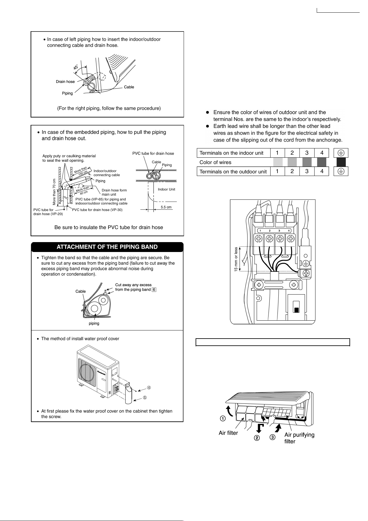
10.3.5. CONNECT THE CABLE TO THE
OUTDOOR UNIT
(FOR DETAIL REFER TIO WIRING DIAGRAM AT UNIT)
1. Remove the control board cover from the unit by loosening
the screw.
2. Indoor/outdoor connecting cable between indoor unit and
outdoor unit shall be approved polychorprene sheathed 5 ×
2.5 mm
RN-F or heavier cord.
3. Secure the cable onto the control board with the holder
(clamper).
4. Attach the control board cover to the original position with
the screw.
2
flexible cord 245 IEC 57 ,type designation HO5
49
Page 50

CS-A28BKP5/CU-A28BKP5
10.3.6. PIPE INSULATION
1. Please carry out insulation at pipe connection portion as
mentioned in Indoor/Outdoor Unit Installation Diagram.
Please wrap the insulated piping end to prevent water from
going inside the piping.
2. If drain hose or connecting piping is in the room (where dew
may form), please increase the insulation by using POLY-E
FOAM with thickness 6 mm or above.
CHECK THE DRAINAGE
1. Pour a glass of water into the drain tray-styrofoam.
2. Ensure if water flows out from drain hose of indoor unit.
EVALUATION OF THE PERFORMANCE
1. Operate the unit at cooling operation mode for fifteen
minutes or more.
2. Measure the temperature of the intake and discharge air.
3. Ensure the difference between the intake temperature and
the discharge is more than 8°C.
CHECK ITEMS
Is there any gas leakage at flare nut connections?
Has the heat insulation been carried out at flare nut
connection?
DISPOSAL OF OUTDOOR UNIT DRAIN WATER
If a drain elbow is used, the unit should be placed on a
•
stand which is taller than 3 cm.
If the unit is used in an area where temperature falls below
•
0°C for 2 or 3 days in succession, it is recommended not to
use a drain elbow, for the drain water freezes and the fan
will not rotate.
Is the indoor/outdoor connecting cable being fixed to terminal
board firmly?
Is the indoor/outdoor connecting cable being clamped firmly?
Is the drainage OK?
(Refer to “Check the drainage” section)
Is the earth wire connection properly done?
Is the indoor unit properly hooked to the installation plate?
Is the power supply voltage complied with rated value?
Is there any abnormal sound?
Is the cooling operation normal?
Is the thermostat operation normal?
Is the remote control’s LCD operation normal?
Is the air purifying filter installed?
50
Page 51

11 3-way Valve
CS-A28BKP5/CU-A28BKP5
3-way Valve (Liquid Side) 3-way Valve (Gas Side)
Works Shaft Position Service Port Shaft Position Service Port
Shipping Close Closed Closed Closed
(With valve cap) (With cap) (With valve cap) (With cap)
Evacuation Closed Open Closed Open
(Installation and (Clockwise) (Connected manifold (Clockwise) (Push-pin)
Re-installation) gauge w/charging
cylinder)
Operation Open Closed Open Closed
(With valve cap) (With cap) (With valve cap) (With cap)
Pumping down Closed Closed Open Open
(Transferring) (Clockwise) (With cap) (Counter-Clockwise) (Connected manifold
Evacuation Open Open Open Open
(Servicing) (Counter-Clockwise) (Connected manifold (Counter-Clockwise) (Connected manifold
gauge) gauge)
Gas charging Open Open Open Open
(Servicing) (Counter-Clockwise) (Connected manifold (Counter-Clockwise) (Connected manifold
gauge) gauge)
gauge)
Pressure check Open Open Open Open
(Servicing) (Counter-Clockwise) (Connected manifold (Counter-Clockwise) (Connected manifold
gauge) gauge)
Gas releasing Open Open Open Open
(Servicing) (Counter-Clockwise) (Connected manifold (Counter-Clockwise) (Connected manifold
gauge) gauge)
51
Page 52

CS-A28BKP5/CU-A28BKP5
11.1. Evacuation of Installation
When installing an air conditioner, be sure to evacuate the air inside the indoor unit and pipes in the following procedure.
Required tools: hexagonal wrench, adjustable wrench,
torque wrenches, wrench to hold the
joints, gas leak detector, and charging
set.
The air in the indoor unit and in the piping must be purged. If air
remains in the refrigeration pipings, it will affect the
compressor, reduce the cooling capacity, and could lead to a
malfunction.
Service port cap
Be sure, using a torque wrench to tighten the service port cap (after using the service port), so that it prevents the gas leakage from the
refrigeration cycle
Procedure:
Connect a charging hose with a push pin to the Low
1.
and High sides of a charging set and the service ports
of a 3-way valve.
Be sure to connect the end of the charging hose with the
•
push pin to the service port.
Connect the centre hose of the charging set to a
2.
vacuum pump.
Turn on the power switch of the vacuum pump and
3.
Tighten the service port caps of both the 3-way valves
6.
at a torque of 18 N.m with a torque wrench.
Remove the valve caps of the 3-way valves. Position
7.
both of the valves to “open” using a hexagonal wrench
(4 mm).
Mount the valve caps onto both of the 3-way valves.
8.
Be sure to check for gas leakage.
•
make sure that the needle in the gauge moves from 0
cmHg (0 MPa) to -76 cmHg (-0.1 MPa). Then evacuate
the air for approximately 10 minutes.
Close the valve of both the Low and High sides of the
4.
charging set and turn off the vacuum pump. Make sure
that the needle in the gauge does not move after
approximately 5 minutes.
BE SURE TO TAKE THIS PROCEDURE IN ORDER TO
Caution
If gauge needle does not move from 0 cmHg (0 MPa)
to -76 cmHg (-0.1 MPa) in step (3) above, take the
following measures:
If the leaks stop when the piping connections are
tightened further, continue working from step (3).
If the leaks do not stop when the connections are
retightened, repair the location of the leak.
AVOID REFRIGERANT GAS LEAKAGE.
Disconnect the charging hose from the vacuum pump
5.
and from the service port of the 3-way valve.
52
Page 53

11.2. Pumping down
CS-A28BKP5/CU-A28BKP5
Procedure:
Confirm that both the 3-way valves are set to the open
1.
position.
Remove the valve stem caps and confirm that the valve
•
stems are in the open position.
Be sure to use a hexagonal wrench to operate the valve
•
stems.
Operate the unit for 10 to 15 minutes.
2.
Stop operation and wait for 3 minutes, then connect the
3.
charge set to the service port of the 3-way valve.
Connect the charge hose with the push pin to the Gas
•
side service port.
Air purging of the charge hose.
4.
Open the low-pressure valve on the charge set slightly
•
to purge air from the charge hose.
Set the Liquid side 3-way valve to the close position.
5.
Operate the air conditioner at the cooling cycle and
6.
stop it when the gauge indicates 0 kg/cm
If the unit cannot be operated at the cool condition
•
2
G (0 MPa).
(weather is rather cool), press the Pump Down Switch
on the Indoor unit.
So that the unit can be operated.
•
Immediately set the gas side 3-way valve to the close
7.
position.
Do this quickly so that the gauge ends up indicating 1 to
•
3 kg/cm
Use refrigerant reclaiming equipment to collect
8.
2
G (0.1 MPa to 0.3 MPa).
refrigerant from indoor unit and pipes.
Disconnect the charge set, and mount both the 3-way
9.
valve’s stem nuts and the service port caps.
Use a torque wrench to tighten the service port cap to a
•
torque of 18 N.m.
Be sure to check for gas leakage.
•
Disconnect pipes from indoor unit and outdoor unit.
10.
53
Page 54

CS-A28BKP5/CU-A28BKP5
11.3. Evacuation of Re-installation
WHEN REINSTALLING AN AIR CONDITIONER, BE SURE TO
EVACUATE THE AIR INSIDE THE INDOOR UNIT AND PIPES
in the following procedure.
If air remain in the indoor unit and refrigeration pipes, it will
affect the compressor, reduce to cooling capacity, and could
lead to a malfunction.
Procedure:
Connect a charging hose with a push pin to the Low
1.
and High sides of a charging set and the service port of
the 3-way valve.
Be sure to connect the end of the charging hose with the
•
push pin to the service port.
Connect the centre hose of the charging set to a
2.
vacuum pump.
Turn on the power switch of the vacuum pump and
3.
make sure that the needle in the gauge moves from 0
cmHg (0 MPa) to -76 cmHg (-0.1 MPa). Then evacuate
the air for approximately 10 minutes.
Close the valve of both Low side and High side of the
4.
charging set and turn off the vacuum pump. Make sure
that the needle in the gauge does not move after
approximately 5 minutes.
BE SURE TO TAKE THIS PROCEDURE IN ORDER TO
AVOID REFRIGERANT GAS LEAKAGE.
Disconnect the charging hose from the vacuum pump.
5.
Charge the pipes and indoor unit with gas refrigerant
6.
from liquid (High) side 3-way valve service port and
then discharge the refrigerant until gas (Low) side
gauge needle indicates 3 kg/cm
2
(0.3 MPa).
BE SURE TO USE REFRIGERANT RECLAIMING
•
EQUIPMENT WHILE DISCHARGING THE
REFRIGERANT.
Purge the air from charge set’s centre hose.
•
Be sure to check for gas leakage.
•
Caution
If gauge needle does not move from 0 cmHg (0 MPA)
to -76 cmHg (0.1 MPa) in step (3) above, take the
following measures:
If the leaks stop when the piping connections are
tightened further, continue working from step 3.
If the leaks do not stop when the connections are
retightened, repair the location of the leak.
Tighten the service port caps of both the 3-way valves
7.
at a torque of 18 N.m with a torque wrench.
Remove the valve caps of both the 3-way valves.
8.
Position both of the valves to “open” using a hexagonal
wrench (4 mm).
Mount the valve caps onto the 3-way valves.
9.
54
Page 55

11.4. Balance refrigerant of the 3-way valves
(Lack of refrigerant in the refrigeration cycle)
CS-A28BKP5/CU-A28BKP5
Procedure:
Confirm that both the 3-way valves are set to the open
1.
position.
Connect the charge set to the 3-way valve’s service
2.
port.
Leave the valve on the charge set closed.
•
Connect the charge hose with the push-pin to the
•
service port.
Confirm whether the pressure indicates more than 0.1
•
MPa (1 kg/cm
Connect the charge set’s centre hose to refrigerant
3.
2
G).
reclaiming equipment.
Open the valve (Low side) on the charge set and loosen
4.
the hose connected with the Refrigerant Reclaiming
Equipment to purge the air from the hose.
Turn on refrigerant reclaiming equipment to collect the
5.
refrigerant until the needle indicates 0 (no refrigerant is
remaining).
55
Page 56

CS-A28BKP5/CU-A28BKP5
11.5. Evacuation
(No refrigerant in the refrigeration cycle)
Procedure:
Connect the vacuum pump to the charge set’s centre
1.
hose.
Turn on the vacuum pump to evacuate the unit.
2.
Confirm that the gauge needle has moved toward -76
•
cmHg (-0.1 MPa).
Apply the vacuum for approximately 1 hour (vacuum of
•
4 mmHg or less).
Close the valve (Low side and High side) on the charge
3.
set, turn off the vacuum pump, and confirm that the
gauge needle does not move (approximately 5 minutes
after the vacuum pump is turned off).
Disconnect the charge hose from the vacuum pump.
4.
56
Page 57

11.6. Gas charging
(After Evacuation)
CS-A28BKP5/CU-A28BKP5
Procedure:
Connect the charge hose to the charging cylinder.
1.
Connect the charge hose which was disconnected from
•
the vacuum pump to the valve at the bottom of the
cylinder.
Purge the air from the charge hose.
2.
Open the valve at the bottom of the cylinder and use a
•
screwdriver to press the check valve on the charge set
to purge the air (be careful of the liquid refrigerant).
Open the High side on the charge set and charge the
3.
refrigerant to the unit.
Be sure to open only the High side valve on the charge
•
set to charge the system from the liquid-side (highpresure) pipe. (If the system cannot be charged with the
specified amount of refrigerant, operate the compressor
until the specified amount can be charged, and then
close the valve at the bottom of the charge cylinder.)
Immediately disconnect the charge hose from both the
4.
3-way valve service ports.
Mount the valve stem nuts and the service port caps
5.
onto the 3-way valves.
Use torque wrench to tighten the service port caps to a
•
torque of 18 N.m.
Be sure to check for gas leakage.
•
57
Page 58

CS-A28BKP5/CU-A28BKP5
12 Servicing Information
(A) Disassembly of the parts (Indoor Unit)
Inspection points for the Indoor Electronic Controller
•
1. The Electronic Controller, a signal Receiver and an
Indicator can be seen by removing the Front Grille and
Control Board Cover, as shown in the .
Fig. 1
Indoor Fan Motor removal procedure:-
•
1. Remove the connector CN-C of Fan Motor and
connector CN-STM of stepping motor from the
electronic controller. Release the earth wire (YELLOWGREEN) from the control board terminal and sensors
from its holders. (Refer .)
2. Remove the Control Board.
As shown in remove the 5 screws. Pull the control board
forward slightly.
Fig. 2
Caution:
Remove of Discharge Grille before removing the
control board is necessary to avoid damaging other
parts.
Fig. 3
58
Page 59
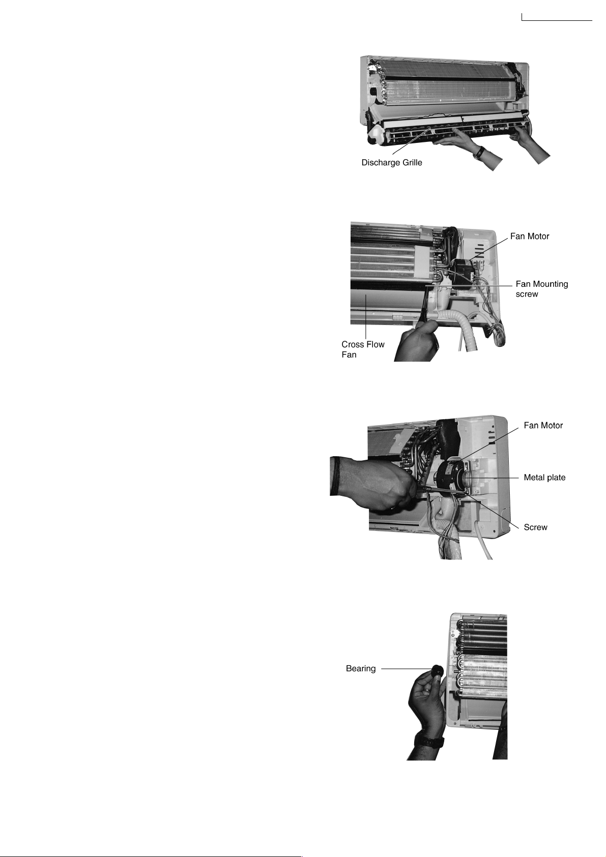
3. Remove the Discharge Grille.
Remove the Discharge Grille and then pull the
Discharge Grille in a down and forward direction.
4. Remove the Indoor Fan Motor.
Loosen the Fan Mounting Screw at the junction with
Cross Flow Fan.
CS-A28BKP5/CU-A28BKP5
Fig. 4
Loosen the screw at the left side of the evaporator.
Pull off the Bearing at the left of the Cross Flow Fan.
Fig. 5
Fig. 6
59
Fig. 7
Page 60
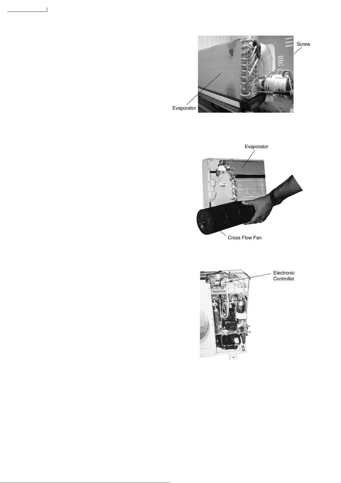
CS-A28BKP5/CU-A28BKP5
Cross Flow Fan Removal Procedure.
•
1. (Refer to No. 4 of Indoor Fan Motor the removal
procedure)
Loosen the screw at the right side of the evaporator.
2. Pull the left side of the evaporator forward slightly and
remove the cross Flow Fan.
Fig. 8
(B) Disassembly of the parts (Outdoor Unit)
Inspection points for the Outdoor Electronic
•
Controller
1. The Electronic Controller, Can be seen by removing the
cabinet Top plate and Front plate, as shown in the .
Fig. 9
Fig. 10
60
Page 61
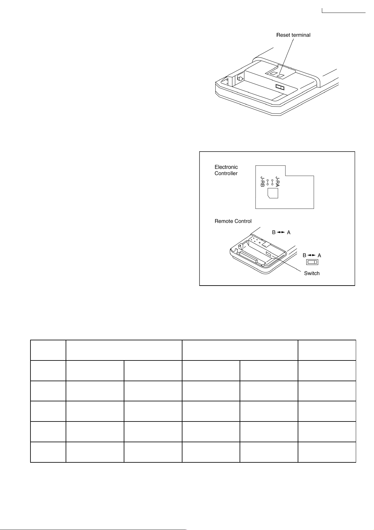
(C) Remote Control Transmission Setting
Remote Control Reset
•
When the batteries are inserted for the first time, or the
batteries are replaced, all the indications will blink and the
remote control might not work.
If this happen, remove the back cover of the remote control
and you will find a resetting terminal, and by shorting it with
a minus screwd river, it will return to normal.
Changing the wireless remote control transmission
•
code
When two indoor units are installed in the same room, in
order to prevent operating errors caused by using two
remote controls, set up the remote control [B
←→
(SW1).
The unit is set to A when it is shipped.
CS-A28BKP5/CU-A28BKP5
A] switch
By adding a jumper wire to the remote control side and CUTTING J-RA, J-RB to the indoor printed circuit board, it is
•
possible to select from 4 types of transmission codes including one at time of delivery condition (1).
Remote Control Indoor printed circuit board Note
Switch SW B
1 A —— SHORT SHORT At product delivery
2 B —— SHORT OPEN
3 A Jumper wire OPEN SHORT
4 B Jumper wire OPEN OPEN
A J-B J-RA J-RB
←→
61
Page 62

CS-A28BKP5/CU-A28BKP5
13 Troubleshooting Guide
13.1. Refrigeration cycle system
In order to diagnose malfunctions, make sure that there are no
electrical problems before inspecting the refrigeration cycle.
Such problems include insufficient insulation, problem with the
power source, malfunction of a compressor and a fan.
The normal outlet air temperature and pressure of the
refrigeration cycle depends on various conditions, the standard
values for them are shown in the table to the right.
62
Page 63
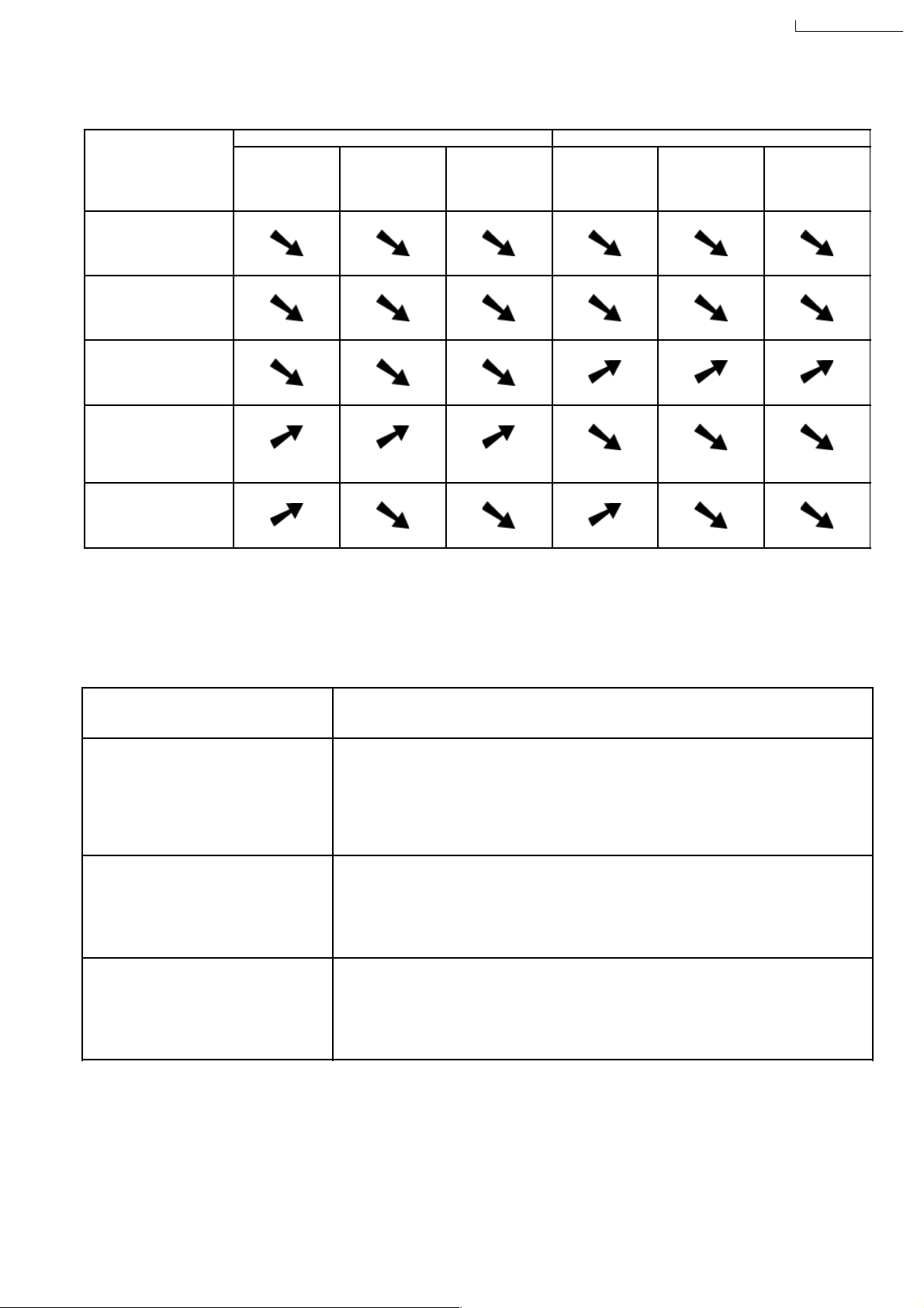
CS-A28BKP5/CU-A28BKP5
13.1.1. Relationship between the condition of the air conditioner and pressure and
electric current
Cooling Mode Heating Mode
Condition of the air
conditoner Low Pressure High Pressure Electric current
during operation
Insufficient refrigerant
(gas leakage)
Clogged capillary tube
or Strainer
Short circuit in the
indoor unit
Heat radiation
deficiency of the
outdoor unit
Low Pressure High Pressure Electric current
during operation
Inefficient compression
•
Carry out the measurements of pressure, electric current, and temperature fifteen minutes after an operation is started.
13.1.2. Diagnosis methods of a malfunction of a compressor and 4-way valve
Nature of fault Symptom
•
Electric current during operation becomes approximately 20% lower than the normal value.
Insufficient compressing of a compressor
Locked compressor
•
The discharge tube of the compressor becomes abnormally hot (normally 70 to 90 °C).
•
The difference between high pressure and low pressure becomes almost zero.
•
Electric current reaches a high level abnormally, and the value exceeds the limit of an
ammeter. In some cases, a breaker turns off.
•
The compressor is a humming sound.
Inefficient switches of the 4-way valve
•
Electric current during operation becomes approximately 80% lower than the normal value.
•
The temperature difference between from the discharge tube to the 4-way valve and from
suction tube to the 4-way valve becomes almost zero.
63
Page 64

CS-A28BKP5
CS-A28BKP5/CU-A28BKP5
14 Technical Data
64
Page 65

CS-A28BKP5 / CU-A28BKP5
CS-A28BKP5/CU-A28BKP5
65
Page 66

CS-A28BKP5/CU-A28BKP5
CS-A28BKP5 / CU-A28BKP5
66
Page 67

15 Exploded View
CS-A28BKP5
CS-A28BKP5/CU-A28BKP5
67
Page 68

CS-A28BKP5/CU-A28BKP5
16 Replacement Parts List
<Model: CS-A28BKP5>
NO DESCRIPTION & NAME QTY CS-A28BKP5 REMARKS
1 CHASSIS COMPLETE 1 CWC5239-970
2 FAN MOTOR 1 CWC4301-370
3 CROSS FLOW FAN COMPLETE 1 CWC5707-260
4 BEARING ASS’Y 1 CWC4059-190
5 SCREW (CROSS FLOW FAN) 1 CWC4582-660
6 EVAPORATOR COMPLETE ASS'Y 1 CWC6325-300
7 TUBE ASS’Y COMPLETE 1 CWC5811-260
8 INSTALLATION PLATE 1 CWC8010-540
9 SENSOR HOLDER 1 CWC5040-130
10 PARTICULAR PLATE 1 CWC4945-610
11 DISCHARGE GRILLE COMPLETE 1 CWC5011-920
12 FULCRUM 3 CWC4525-110
13 MOTOR - AIR SWING 1 CWC4107-010
14 VANE AIR DEFLECTOR ASS’Y 1 CWC5050-870
15 DRAIN HOSE 1 CWC5881-720
16 TRANSFORMER 1 CWC4017-690
17 CONTROL BOARD ASS’Y 1 CWC4719-220
18 PARTICULAR PLATE 1 CWC4945-600
POWER SUPPLY COMPLETE CWC4102-760
19 1
20 CIRCUIT ASS’Y (OPERATION BUTTON COMPLETE) 1 CWC3919-720
21 CIRCUIT ASS’Y (RECEIVER COMPLETE) 1 CWC3919-640
22 CIRCUIT ASS’Y (DISPLAY COMPLETE) 1 CWC3919-710
23 CIRCUIT ASS’Y (ELECTRONIC CONTROLLER) 1 CWC3919-420A
24 TERMINAL BOARD ASS’Y 1 CWC4706-600
BAG COMPLETE - INSTALLATION SCREW
25 1
26 FUSE COMPLETE
27 TERMINAL BOARD COMPLETE 1 CWC4706-620
28 SENSOR COMPLETE 1 CWC3900-230
29 CONTROL BOARD TOP COVER 1 CWC4945-590
30 HOLDER - P.S. CORD 1 CWC4627-040
31 CAP (BUTTON) 1 CWC5060-120
32 REMOTE CONTROL COMPLETE ASS’Y 1 CWA75C556
33 FRONT GRILLE COMPLETE 1 CWC5053-360
34 DECORATING PLATE COMPLETE 1 CWC5027-410
35 DOOR 1 CWC5002-270
36 INTAKE GRILLE COMPLETE 1 CWC5010-960
37 AIR FILTER (LEFT) 1 CWD4209550
38 AIR FILTER (RIGHT) 1 CWD4209540
39 SCREW - FRONT GRILLE 4 XTT4+16C
40 CAP (FRONT GRILLE COMPLETE) 4 CWC5060-060
41 BAG COMPLETE (AIR PURIFYING FILTER) 1 CWC4649-920
42 SOLAR REFESHING DEODORIZING FILTER 1 CZ-SFD71P
43 CATECHIN AIR PURIFYING FILTER 1 CZ-SF71P
44
OPERATING INSTRUCTIONS
45 1
INSTALLATION INSTRUCTIONS CWC8039-270
1
1
CWC4649-210
CWC4023-070
CWC8037-130
●
■ ●
●
●
●
●
●
●
●
●
●
●
■●
●
●
●
●
■●
■ ●
■●
■●
■ ●
■ ●
■●
●
■●
●
■●
●
●
■ ●
■▲
■ ●
●
●
●
■ ●
■ ●
●
●
●
●
●
●
●
(Note)
“■” marked parts are recommended to be kept in stock.
•
“●” marked parts are supplied from TAMACO, Taiwan.
•
“▲” marked parts are supplied from MACC, Malaysia.
•
68
Page 69

17 ExplodedView
CU-A28BKP5
CS-A28BKP5/CU-A28BKP5
69
Page 70

CS-A28BKP5/CU-A28BKP5
18 Replacement Parts List
<Model: CU-A28BKP5>
NO DESCRIPTION & NAME QTY CU-A28BKP5 REMARKS
1 CHASSIS ASS’Y 1 CWC5244-200A
2 SOUND PROOF 1 CWC5236-060
3 FAN MOTOR BRACKET 1 CWC5241-830
4 SCREW - (FAN MOTOR BRACKET) 6 XTT4D10CXW
5 PARTICULAR PLATE - LEFT (HOLD - FAN MOTOR) 1 CWC4934-850
6 PARTICULAR PLATE - RIGHT (HOLD - FAN MOTOR) 1 CWC4934-860
7 FAN MOTOR 1 CWC4301-380
8 SCREW - FAN MOTOR 3 XTT4D10CXW
9 PROPELLER FAN ASS’Y 1 CWC5700-500
10 NUT - PROPELLER FAN 1 CWC4583-020
11 HOLDER - FOR F/MOTOR & LEAD WIRES 3 CWC4620-110
12 COMPRESSOR 1 CWC6815-280
13 PACKING - COMP. MOUNT 3 CWC4604-010
14 NUT - COMP. MOUNT 3 CWC4521-130
15 CONDENSER 1 CWC6305-570
16 HOLDER - COUPLING ASS’Y 1 CWC5240-070A
17 3-WAYS VALVE (LIQUID) 1 CWC4034-150
18 3-WAYS VALVE (GAS) 1 CWC4034-170
19 4-WAYS VALVE ASS'Y 1 CWC4034-740
20 V-COIL COMPLETE 1 CWC4019-400
21 STRAINER 1 CWC4042-340
22 TUBE ASS'Y (CAPILLARY TUBE.CHECK VALVE) 1 CWC5932-090
23 CONTROL BOARD ASS’Y 1 CWC4712-690
24 CAPACITOR - FAN MOTOR 1 CWC4069-960
25 CAPACITOR - COMPRESSOR 1 CWC4069-780
26 HOLDER - CAPACITOR 1 CWC4828-750
27 TERMINAL BOARD ASS’Y 1 CWC4706-590
28
ELECTRONIC CONTROLLER
29 SENSOR COMPLETE 1 CWC3900-240
30 HOLDER - SENSOR 1 CWC5040-130
31 HOLDER - SENSOR (FOR TUBE) 1 CWC5040-120
32 U METAL PIECE
33
MUFFLER
34
WIRE NET (REAR)
35
POLY-E FOAM
36
37 POLY-E FOAM 1 CWN5A30-325
CABINET TOP PLATE ASS’Y
38
39 CONTROL BOARD COVER 1 CWC4936-960A
40 HANDLE 2 CWC4520-120
41 RAIN COVER 1 CWC4631-880
42 SCREW 1 XYN4+C8D
43 SCREW 20 CWC4585-520
44
SCREW CWC4580-930
45 CABINET ASS’Y 1 CWC5030-940A
46 1
CABINET FORNT PLATE ASS'Y
CABINET SIDE PLATE (LEFT)
47 1
CABINET REAR PLATE COMPLETE
48
1
CWC3919-670
CWC4825-120
1
CWC4627-100HOLDER-PS,CORD
1
CWC6040-320
1
CWC4537-530A
1
CWE3A325-360
1
1 CWC5030-520A
4
CWC5030-640
CWC5030-720A
1 CWC5030-820
●
●
●
●
●
●
■ ●
●
■ ●
●
●
■ ●
●
●
●
●
■ ●
■●
■●
■●
●
●
●
■ ●
■ ●
●
■ ●
■ ●
■ ●
●
●
●
●
●
●
●
●
●
●
●
●
●
●
●
●
●
●
●
(Note)
“■” marked parts are recommended to be kept in stock.
•
“●” marked parts are supplied from TAMACO, Taiwan.
•
“▲” marked parts are supplied from MACC, Malaysia.
•
70
Page 71

19 Electronic Parts List
Electronic Controller: C3919-420A (CS-A28BKP5)
SYMBOL DESCRIPTION & NAME PART NO.
IC1 INTEGRATED CIRCUIT C4083-910
IC2
IC3 INTEGRATED CIRCUIT C4083-860
IC4 INTEGRATED CIRCUIT C4083-730
IC5 INTEGRATED CIRCUIT C4083-720
PC1 PHOTO COUPLER C4094-040
Q1 TRANSISTOR C4086-060T
Q2 TRANSISTOR C4086-240T
Q3, Q5 TRANSISTOR J4086-080T
D1 ~ D4 DIODE E4060-020T
ZD1 ZENER DIODE C4082-100T
ZNR1, ZNR2, ZNR3 ZNR C4084-150
RY-HOT RELAY ELECTRO MAGNETIC C4104-180
RY-HI, ME, LO RELAY ELECTRO MAGNETIC C4104-170
RY-COMP RELAY ELECTRO MAGNETIC C4076-310
SSR1 SSR C4092-070
SW1, SW2 PUSH SWITCH C4001-200
FUSE FUSE XBA2C31TR0
X1 RESONATOR F4090-010T
BZ BUZZER (SOUND GENERATOR) C4091-030
Q6~ Q8
Note
All parts are supplied from TAMACO, Taiwan.
•
INTEGRATED CIRCUIT C4083-450
TRANSISTOR
CS-A28BKP5/CU-A28BKP5
C4086-250T
Electronic Controller: CWC3919-670 (CU-A28BKP5)
SYMBOL DESCRIPTION & NAME PART NO.
IC1 INTEGRATED CIRCUIT C4083-950A
IC2 INTEGRATED CIRCUIT C4083-720
IC3 INTEGRATED CIRCUIT C4083-730
IC4 INTEGRATED CIRCUIT C4083-450
Q1 TRANSISTOR C4086-060T
Q2 TRANSISTOR C4086-240T
D1 ~ D12 DIODE E4060-240T
ZD1
ZNR1 ~ ZNR3 ZNR C4084-150
T1, T2
CR1 SURGE ABSORBER
RY-HOT
RY-DEICE
RY-OFF
RY-H/L
FUSE
X1
ZENER DIODE
TRANSFORMER
RELAY
RELAY
RELAY
RELAY
FUSE XBA2C31TR0
RESONATOR
Note
All parts are supplied from TAMACO, Taiwan.
•
C4082-100T
C4017-780
C4085-560
C4104-170
C4107-170
C4107-170
C4107-170
A45ST4.0MGWT
71
Page 72

CS-A28BKP5/CU-A28BKP5
20 Electronic Circuit Diagram
• CS-A28BKP5 / CU-A28BKP5
SCHEMATIC DIAGRAM 1/3
ELECTRONIC CIRCUIT
CN-SW-B
1
PUMP DOWN
AUTO RUN
INTAKE AIRE TEMPERATURE
SENSOR (15K,3950)
RCV
SW1
2
SW2
3
PH-3
PIPE TEMPERATURE
SENSOR (20K,3950)
RCV
1
2
3
CN-RCV-B
EH-3
1
2
3
4
3
2
1
1
2
3
CN-SW-A
PH-3
CN-TH
XH-4
12V
CN-RCV-A
EH-3
ZD1
MTZJ7.5B
+
C5
10uF/16V
R8
10k
R4
15K
R20
20K
C22
103
R5
4.7K
Q2
DTC113ZS
R9
1K
C4
103
C9
1µF/50V
R10
10K
R11
10K
+
10uF/16V
+
C3
10uF/16V
R6
100K
Q1
2SC1740
+
C8
103
C21
R14
5.1K
10K
C11
R1
1K
C1
103
R2
1K
C2
103
R7
C7
103
S-TEST
R3
1K
100u/6.3V
R12
10K
C17
C16
104
X1
CST4.0MGW
R16
10K
+
R13
10K
R15
1K
+
220u/6.3V
F-TEST
R17
1M
C4083-910
IC1
1
TCMP1
2
PD7
3
PD6
4
PD5
5
NC
6
NC
7
NC
8
VRL
9
VRH
10
PD4
11
VDD
12
PD3
13
PD2
14
PD1
15
PD0
16
NC
17
OSC1
18
OSC2
19
RESET
20
IRQ
21
PLMA
22
PLMB
23
TCAP1
24
TCAP2
25
PA7
26
PA6
27
PA5
28
PA4
TCMP2
TD0
SCLK
RDI
PC0
PC1
PC2
PC3
PC4
PC5
PC6
PC7
VSS
PB0
PB1
PB2
PB3
PB4
PB5
PB6
PB7
PA0
PA1
PA2
PA5
NC
NC
NC
56
55
54
53
52
51
50
49
48
47
46
R25
1K
45
R26
1K
44
43
42
41
40
470
39
R27
38
470
R28
37
470
R29
36
35
34
33
32
31
30
29
C14
104
R19
10K
Q3
DTC114ES
+
220uF/6.3V
72
C26
+
C6
220uF/6.3V
C15
104
IC4 AN7805
O I
+5V
G
R18
5.1K
12V
C13
104
Page 73

SCHEMATIC DIAGRAM 2/3
LED1
POWER
LED3
TIMER
LED2
SLEEP
CS-A28BKP5/CU-A28BKP5
10K
4
4
Q8
DTD123YS
PH-4
CN-LED-B
CN-LED-A
PH-4
R21
1k
10u/16V
C18
R33
1.82K
+
12V
12V
12V
12V
12V
12V
D6
1N4003
SSR101
W2DEH1-5
D5
1N4003
D7
1N4003
432
RY-LO
ON
RY-ME
ON
RY-HI
ON
RY-HOT
RY-COMP
ON
COM
PC1
P521
1
CN-FM
VH-7
C19
103
47K/2W
LO ME
SLO
123
ZNR3
10DK511
FUSE
AC250V/3.15A
ZNR1
10DK511
R23
R24
47K/2W
ZNR2
10DK511
123
123
93LC46B
IC3
1 CS VCC 8
2 CLK
3 DI
JX
RA1
10K
J_RB
J_RA
Q7
DTD123YS
4 DO
Q4
DTC114ES
RX
GND 5
BZ1
1K
R32
Q6
DTD123YS
C10
104
FAN
HI
4
VH-3
CN-C
C23
2u/450V
HOT
T1
T2
1
2
3
TEMPERATURE
FUSE(99 )
DEICE
AC
220V~230V
50Hz
BLU
BRW
BLK
WHT
RED
℃
BLU
1
2
3
4
IC2
ULN2003AP
12V
CN-STM
B5B-PH
1
2
3
4
5
STEPPING MOTOR
73
R22
10K
12V
+
C12
100uF/25V
IC5
+12V
7812
IO
G
2200uF/25V
+
C20
D1
1N4003D21N4003
D4
1N4003D31N4003
CN-FUSE
3
XH-3
1
2
TEMPERATURE FUSE
T3
2
1
CN-TR
VH-2
TRANSFORMER
Page 74
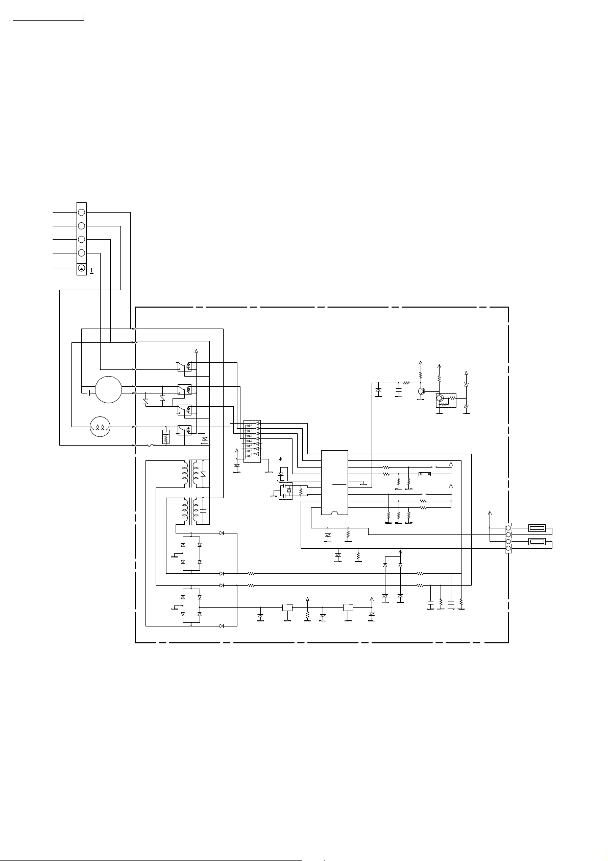
CS-A28BKP5/CU-A28BKP5
SCHEMATIC DIAGRAM 3/3
1
2
3
4
CAPACITOR
FM
4 WAY VALVE
REVERSING COIL
COMP(VLT)
HOT1(RED)
DEICE()GRY
FM2(ORG)
FM1(BRY)
ZNR3
10DK511
HOT2(BLK)
AC(WHT)
FUSE
3.15A
CR1
ZNR2
10DK511
RY-DEICE
RY-HI/LO
RY-OFF
RY-HOT
D2
1N4003
D3
1N4003
D6
1N4003
D8
1N4003
ON
ON
ON
ON
100uF/35V
C14
T2
T1
12V
+
ZNR1
10DK511
C13
0.01u/250VAC
D1
1N4003
D4
1N4003
D5
1N4003
D7
1N4003
D9
1N4003
D10
1N4003
D12
1N4003
D11
1N4003
12V
+
IC4
ULN2003AP
C15
100uF/35V
R8
R7
100K
R9
Q1
1K
+
C11
C12
103
1uF/50V
IC1
10
11
C4
10uF/16V
CST4.0MGW
R22
18K
R23
18K
+
C1
2200uF/35V
IC?
IC-3P-7812-1
12
+
13
14
15
R22
16
X1
1M
17
18
PIC16C711
12V
OI
+12V
R24
G
10K
RB4
RB5
RB6
RB7
VDD
OSC2
OSC1
RA0
RA1
+
C2
100uF/35V
+
MCLR
C6
22uF/10V
RB3
RB2
RB1
RB0
VSS
RA4
RA3
RA2
+
C5
22uF/10V
IC?
IC-3P-78N05-1
I O
+5V
G
9
8
7
R17 1K
6
R16 1K
5
4
3
2
1
R2
15K
R13
10K
R1
5.9K
D14
1S336
+
C9
33uF/35V
5V
C3
+
100uF/10V
R19
10K
R14
10K
D13
1S336
+
C10
33uF/35V
2SC1740
F_TEST
TEST
NH-2
R18
10K
R12
1K
R11 4.7K
R10 470
R15
10K
R3
5.1K
R5
5.1K
C8
103
12V
4.7K
ZD1
MTZJ7.5B
Q2
C16
+
10uF/16V
DTC113ZS
INTAKE AIRE TEMPERATURE
SENSOR (15K,3950)
1
2
3
4
PIPE TEMPERATURE
SENSOR (4.96K,3950)
XH-4
R6
R4
C7
20K
20K
103
74
Page 75

CS-A28BKP5/CU-A28BKP5
75
Page 76

How to use electronic circuit diagram
CS-A28BKP5/CU-A28BKP5
TIMER TABLE
Sleep Mode Operation 8 hrs. 48 sec.
Real Timer 10 min. 10 sec.
Time Delay Safety Control 3 min. 0 sec.
Forced Operation 60 sec. 0 sec.
Time Save Control 7 min. 42 sec.
Anti-Freezing Control 4 min. 0 sec.
Mode Judgement 20 sec. 0 sec.
Soft Dry Off 6 min. 36 sec.
Deodorizing Control
After Deice Ended 30 sec. 3 sec. Comp. OFF, F/Motor ON
4-Way valve 5 min. 30 sec.
Test mode
Name Time (When test point Remarks
Short-circuited)
Sleep Mode Waiting 1hr. 6 sec.
1hr. 1 min.
1 min. 1 sec.
On 10 min. 60 sec. SOFT DRY: 10 min. operation
40 sec. 4 sec. Comp. ON
Cooling 70 sec. 7 sec. Comp. ON
20 sec. 2 sec. Comp. OFF
180 sec. 18 sec. Comp. OFF
Soft Dry 40 sec. 4 sec. Comp. ON
360 sec. 36 sec. Comp. OFF
76
Page 77
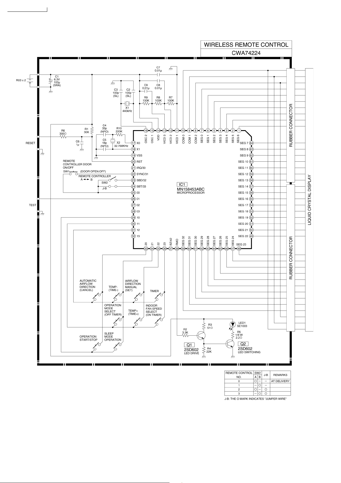
CS-A28BKP5/CU-A28BKP5
20.1. REMOTE CONTROL
77 Printed in Taiwan
 Loading...