

Page 1
¡Please read these instructions carefully before using this product and save this manual for future use.
¡Prière de lire ces instructions attentivement avant d’utiliser le produit et garder ce manuel pour l’utilisation ultérieure.
¡Lea con atención estas instrucciones antes de utilizar el producto y guarde este manual para poderlo consultar en el futuro.
Removable Front CD Player/Receiver with DSP and
CD Changer Control
Lecteur de CD avec façade amovible - récepteur
avec DSP et commande de changeur CD
Reproductor de CD/receptor con DSP y control de
cambiador de CD de panel frontal extraíble
CQ-DRX901U
-
HEQ
-
POSI
-
BAL/FAD
-
GEQ
MUTE
SPEAKER
OPEN/CLOSE
TUNE P·SET
DISP REMOTE
APM
TILT
POWER
SEL
TRACK
DISC
D
VOL
BAND
OPEN
SOURCE
HIGH ENERGHIGH ENERGY
Neodymium MagnetNeodymium Magnet
Center Speaker
HIGH ENERGY
Neodymium Magnet
Center Speaker
CQ-DRX901U
CD RECEIVER WITH DSP & CHANGER CONTROL MOSFET
45Wx4+5
Hu
m
an E
qua
lizer
®
Operating Instructions
Manuel d’instructions
Manual de Instrucciones
Operating Instructions
Manuel d’instructions
Manual de instrucciones
Page 2
2
CQ-DRX901U
E
N
G
L
I
S
H
Radio Frequency Interference Statement (Part 15 of the
FCC Rules) :
Applies only in U.S.A.
This equipment has been tested and found to comply with the limits for a Class B digital, pursuant to Part
15 of the FCC Rules.
¡These limits are designed to provide reasonable protection against harmful interference in an automo-
bile installation. This equipment generates, uses, and can radiate radio frequency energy and, if not
installed and used in accordance with the instructions, may cause harmful interference to radio communications. However, there is no guarantee that interference will not occur in a particular installation. If
this equipment does cause harmful interference to radio or television reception, which can be determined by turning the equipment off and on, the user is encouraged to consult the dealer or an experience radio technician for help.
FCC Warning:
Any unauthorized changes or modifications to this equipment would void the user's authority to operate
this device.
This device complies with Part 15 of the FCC Rules:
Operation is subject to the following two conditions:
a This device may not cause harmful interference, and
s This device must accept any interference received, including interference that may cause undesired
operation.
For Canada:
This Class B digital apparatus complies with Canadian ICES-003.
Find the model number and serial number on either
the back or bottom of the unit. Please record them in
the space below and retain this booklet as a permanent record of your purchase to help with identification in case of theft.
MODEL NUMBER CQ-DRX901U
SERIAL NUMBER
DATE PURCHASED
FROM
CAUTION:
THIS PRODUCT IS A CLASS I LASER PRODUCT.
USE OF CONTROLS OR ADJUSTMENTS OR
PERFORMANCE OF PROCEDURES OTHER
THAN THOSE SPECIFIED HEREIN MAY RESULT
IN HAZARDOUS RADIATION EXPOSURE.
DO NOT OPEN COVERS AND DO NOT REPAIR
YOURSELF. REFER SERVICING TO QUALIFIED PERSONNEL.
WARNING:
TO REDUCE THE RISK OF FIRE OR ELECTRIC
SHOCK, DO NOT EXPOSE THIS PRODUCT TO
RAIN OR MOISTURE.
TO REDUCE THE RISK OF FIRE OR ELECTRIC
SHOCK, AND ANNOYING INTERFERENCE,
USE ONLY THE INCLUDED COMPONENTS.
Laser products:
Wave length: 780 nm
Laser power: No hazardous radiation is emitted
with safety protection.
Safety Information
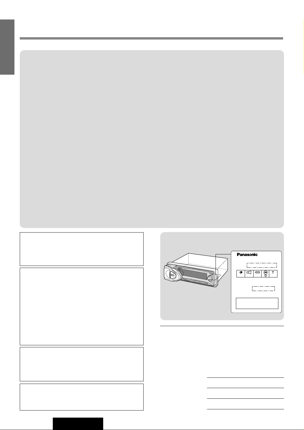
Label Indication and Location
Model No.
CQ-DRX901U
N° De Modèle
1 2 V 10 A
4‘8Ω
Manufactured by Matsushita Communication
Industrial Co., Ltd.
Yokohama Japan Made in Japan
Serial No.
N° De Série
This device complies with Part 15 of the
FCC Rules. Operation is subject to the
condition that this device does not cause
harmful interference.
FM75Ω
Page 3
3
CQ-DRX901U
F
R
A
N
Ç
A
I
S
E
S
P
A
Ñ
O
L
ATTENTION:
CET APPAREIL EST UN PRODUIT LASER DE LA
CLASSE 1.
L'UTILISATION DE COMMANDES OU RÉGLAGES OU
L'EXÉCUTION D'OPÉRATIONS AUTRES QUE CELLES
QUI SONT INDIQUÉES DANS CE DOCUMENT PEUVENT RÉSULTER EN UNE EXPOSITION À UN RAYONNEMENT DANGEREUX.
N'OUVREZ PAS LES COUVERCELS ET N'ESSAYEZ
PAS D'EFFECTUER VOUS-MÊME DES RÉPARATIONS. ADRESSEZ-VOUS À UN PERSONNEL QUALIFIÉ POUR TOUTE RÉPARATION.
MISE EN GARDE:
POUR RÉDUIRE LES RISQUES D'INCENDIE OU
D'ÉLECTROCUTION, N'EXPOSEZ PAS CET APPAREIL
À LA PLUIE OU À L'HUMIDITÉ.
AFIN DE PRÉVENIR TOUT RISQUE D'INCENDIE OU
D'INTERFÉRENCES, UTILISER UNIQUEMENT LES
COMPOSANTS FOURNIS.
Produits laser:
Longueur d'onde: 780 nm
Puissance du laser: Aucune radiation dangereuse
n'est émise avec la protection
de sécurité.
PRECAUCIÓN:
ÉSTE ES UN PRODUCTO LÁSER DE LA CLASE 1.
LA UTILIZACIÓN DE CONTROLES, EL HACER
AJUSETES O EL SEGUIR PROCEDIMIENTOS DISTINTOS DE LOS ESPECIFICADOS EN ESTE MANUAL
PODRÍA CAUSAR UNA EXPOSICIÓN PELIGROSA A
LA RADIACIÓN.
NO ABRA LAS CUBIERTAS NI HAGA REPARACIONES
USTED MISMO. SOLICITE LOS TRABAJOS DE SERVICIO AL PERSONAL CALIFICADO.
ADVERTENCIA:
PARA REDUCIR EL RIESGO DE INCENDIOS O SACUDIDAS ELÉCTRICAS, NO EXPONGA ESTE PRODUCTO A LA LLUVIA NI A LA HUMEDAD.
PARA REDUCIR RIESGO DE INCENDIOS O SACUDIDAS ELÉCTRICAS, Y PARA EVITAR LAS INTERFERENCIAS MOLESTAS, UTILICE SOLAMENTE LOS
COMPONENTES INCLUIDOS.
Productos láser:
Longitud de onda: 780 nm
Potencia láser: Con protección de seguridad no se
emite radiación peligrosa.
Consignes de sécurité
Información para seguridad
ll est recommandé de noter, dans l'espace prévu
cidessous, les numéros de modèle et de série inscrits
soit à l'arrière soit sons le fond de l'appareil, et de
conserver ce manuel comme mémorandum de
l'achat afin de permettre l'identification de l'appareil
en cas de vol.
NUMÉRO DE MODÉLE CQ-DRX901U
NUMÉRO DE SÉRIE
DATE DE L'ACHAT
VENDEUR
Busque el número del modelo y el número de serie
ya sea en la parte trasera o en el fondo de la unidad.
Sírvase anotar dichos números en el espacio siguiente, y mantenga este librete como una anotación
permanente de su compra para ayudar en la identificación en el caso de robo.
NÚMERO DEL MODELO CQ-DRX901U
NÚMERO DE SERIE
FACHA DE COMPRA
NOMBRE DE LA TIENDA
Déclaration d'interférence de fréquences
radio (Partie 15 des Règlements FCC):
Cet appareil numérique de Classe B est conforme
au règlement ICES-003 canadien.
Page 4

4
CQ-DRX901U
E
N
G
L
I
S
H
Panasonic welcomes you to our ever growing family of electronic product owners. We know that this
product will bring you many hours of enjoyment. Our reputation is built on precise electronic and mechanical engineering, manufactured with carefully selected components and assembled by people who take
pride in their work. Once you discover the quality, reliability, and value we have built into this product, you
too will be proud to be a member of our family.
When Driving
Keep the volume level low enough to be aware of
road and traffic conditions.
When Car Washing
Do not expose the product, including the speakers
and CDs to water or excessive moisture. This could
cause electrical shorts, fire, or other damage.
When Parked
Parking in direct sunlight can produce very high
temperatures inside your vehicle. Give the interior a
chance to cool down before switching the unit on.
Use the Proper Power Supply
This product is designed to operate with a 12 volt,
negative ground battery system (the normal system
in a North American car.).
Disc Mechanism
Do not insert coins or any small objects. Keep
screwdrivers and other metallic objects away from
the disc mechanism and disc.
Use Authorized Service Centers
Do not attempt to disassemble or adjust this precision product. Please refer to the service center list
included with this product for service assistance.
For Installation
The product should be installed in a horizontal position with the front end up at a convenient angle, but
not more than 30˚.
❏ Use This Product Safely
Note: This manual focuses on remote control operations. For functions not controlled from the
remote controller, the manual describes how to use the buttons on the main unit.
❏ Components
¡Operating Instruction . . . . . . . . . . . . . . . . . . . . . . . . . 1
¡Installation Hardware . . . . . . . . . . . . 1 set (a page 34)
¡Remote Control Unit . . . . . . . . . . . . . . . . . . . . . . . . . . 1
¡Lithium battery (CR2025) . . . . . . . . . . . . . . . . . . . . . . 1
¡Warranty Card. . . . . . . . . . . . . . . . . . . . . . . . . . . . . . . 1
Page 5

5
CQ-DRX901U
E
N
G
L
I
S
H
Features
This 1-DIN system is equipped with a CD player, FM/AM tuner, CD changer
controller and high power amplifier with high tone 45 W x 4 channels.
Various sound control functions
¡Space function of 3-mode DSP (a page 28), Equalizer: HEQ (Human Equalizer) and GEQ (Graphic Equalizer) (a page 22).
¡Super bass sound: DDBC (Digital Dynamic Bass Control) (a page 28), SDBB (Super Dynamic Bass Boost) (a page 24).
¡CD changer control (a page 18).
Anti-Theft removable face
You can remove the panel when you leave your car.(a page 39).
Caractéristiques
Ce système 1-DIN est équipé d’un lecteur de CD, d’un tuner FM/AM, d’une
commande de changeur de CD et d’un amplificateur de puissance de 45 W x
4 canaux.
Une variété de fonctions de réglage du son
¡Fonction ambiophonique du processeur de son numérique à 3-mode (a page 66), Egaliseur : HEQ (Human Equalizer -
Correcteur sensitif humain ) et GEQ (Graphic Equalizer - Correcteur graphique) (a page 60)
¡Tonalité hyper grave : DDBC (Commande numérique dynamique de basses fréquences) (a page 66), SDBB (Super
graves dynamiques poussés) (a page 62)
¡Commande de changeur de CD (a page 56)
Façade amovible anti-vol
Vous pouvez déposer le panneau en quittant votre voiture. (a page 77)
Características
Este sistema 1-DIN está provisto de un reproductor de CD, sintonizador de
FM/AM, controlador de cambiador de discos CD y de un amplificador de alta
potencia de 4 canales con 45 W por canal.
Diversas funciones de control del sonido
¡Función de espacio de DSP de 3 modos (a página 104), Ecualizador (HEQ (ecualizador humano) y GEQ (ecualizador
gráfico) (a página 98).
¡Sonido de graves súper: DDBC (control de graves dinámicos digital) (a página 104), SDBB (graves súper dinámicos)
(a página 100).
¡Control de cambiador de discos CD (a página 94).
Panel extraíble antirrobo
Podrá extraer el panel cuando salga del automóvil. (a página 115).
E
S
P
A
Ñ
O
L
F
R
A
N
Ç
A
I
S
Page 6
6
CQ-DRX901U
E
N
G
L
I
S
H
Contents
Safety Information........................................................................................... Page 2
Radio Frequency Interference Statement (Part 15 of the FCC Rules)..................... 2
Use this Product Safely ........................................................................................... 4
Components ............................................................................................................ 4
Features .................................................................................................................. 7
¢ Remote Control Unit Preparation ................................................................. 11
Battery Installation and battery notes
¢ General ............................................................................................................ 12
Power, source change, volume, clock setting, display change, etc.
¢ Radio ............................................................................................................... 14
Manual and automatic tuning, band selection, memory preset stations
¢ CD Player ........................................................................................................ 16
Loading/ejecting a disc, CD play, track selection, search, repeat, random, scan and
display change
¢ CD Changer .................................................................................................... 18
Disc/track selection, search, repeat, random, and scan
¢ Useful Functions ............................................................................................ 20
Spectrum Analyzer Display, Dimmer, Mute/Attenuator
¢ Sound Settings and Sound Space ............................................................... 22
Tone Quality, Balance and Fader, Center Speaker, Sub Woofer, etc.
¢ Other Settings ................................................................................................ 30
Beep, Navi Mute, Security Indicator, etc.
¢ Installation Guide ........................................................................................... 34
Step-by-step procedures
¢ Anti-Theft System .......................................................................................... 39
Place the removable face plate into case, install removable face plate and security
indicator
¢ Electrical Connections .................................................................................. 40
Cautions and cable wiring diagram
¢ Troubleshooting ............................................................................................. 42
Where to get service help, troubleshooting tips, error display messages and reset
switch
¢ Maintenance ................................................................................................... 47
Care of the unit, notes on CD
¢ Specifications ................................................................................................. 48
Page 7
11
CQ-DRX901U
1
E
N
G
L
I
S
H
Remote Control Preparation
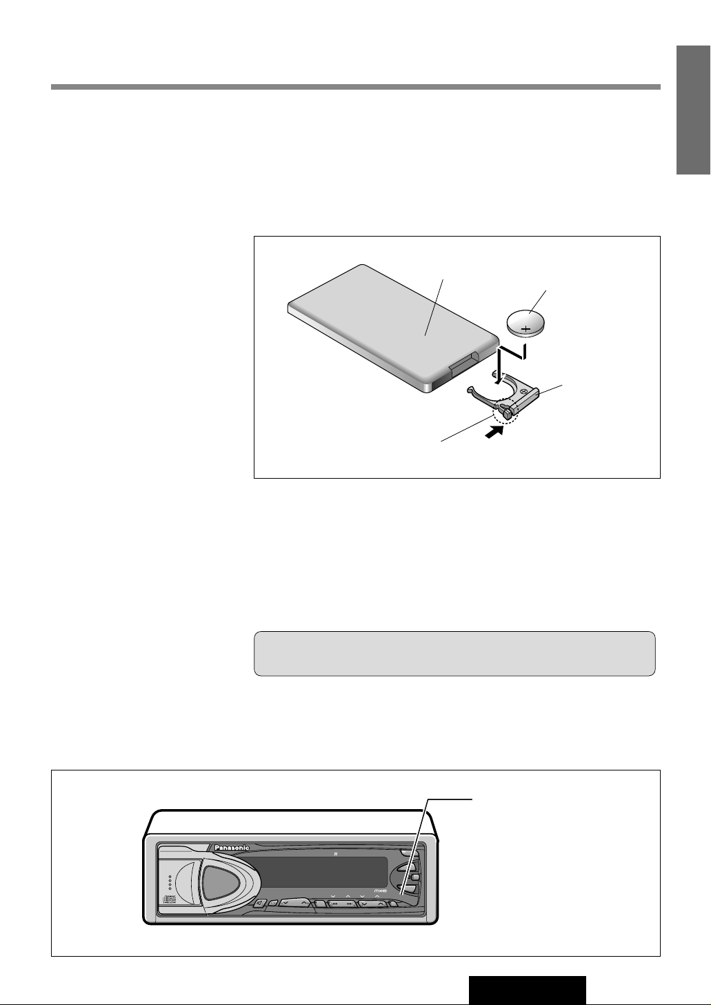
Battery Installation
1. Remove the battery holder.
Take hold of the holder at position B and pull it out by pushing position A in
the direction shown by the arrow.
2. Install the battery on the battery holder.
Set a new battery properly with its (+) side facing up as shown in the figure.
3. Insert the battery holder.
Push the battery holder back into its original position.
Battery Notes
Remove and dispose of an old battery immediately.
Battery Information:
¡Battery Type: Panasonic lithium battery (CR2025)
¡Battery Life: Approximately 6 months under normal use (at room temperature)
(Back side)
Lithium battery
Position B
Position A
Battery holder
¡Do not disassemble or short the battery. Do not throw a battery into a fire.
¡Keep batteries away from children to avoid the risk of accidents.
¡Be careful to the disposal rules when you dispose of batteries.
Caution: Improper use of batteries may cause overheating, an explosion
or ignition, resulting in injury or a fire. Battery leakage may damage the unit.
-
HEQ
-
POSI
-
BAL/FAD
-
GEQ
MUTE
SPEAKER
OPEN/CLOSE
TUNE P· SET
DISP REMOTE
APM
TILT
POWER
SEL
TRACK
DISC
D
VOL
BAND
OPEN
SOURCE
HIGH ENERGY
Neodymium MagnetNeodymium Magnet
Center SpeakerCenter Speaker
HIGH ENERGY
Neodymium Magnet
Center Speaker
CQ-DRX901U
CD RECEIVER WITH DSP & CHANGER CONTROL MOSFET
45Wx4+5
Human Equalizer
Point the remote control
unit at the main unit's
sensor (REMOTE).
Page 8
General
CQ-DRX901U
S-ANALYZER
DIMMER
TUNE P·SET
TILT
POWER
S·A
DIMR
SPC
SEL
TRACK
DISC
D
SUB·W
VOL
BAND
OPEN
SOURCE
CD RECEIVER WITH DSP & CHANGER CONTROL MOSFET
45Wx4+5
Human Equalizer
-
HEQ
-
POSI
-
BAL/FAD
-
GEQ
APM
MUTE
SPEAKER
OPEN/CLOSE
DISP REMOTE
D
VOL
TRACK
SOURCE
DISC
Volume
[{][}]
[]][[]
[DISP]
Power/Source
(Hold to switch
off the power)
Advance
Hour adjust
Back
Minute adjust
Radio
CD Player
CD Changer
AUX In
(When a CD is inserted)
(When CD Changer is connected)
(When AUX-IN setting is activated
j
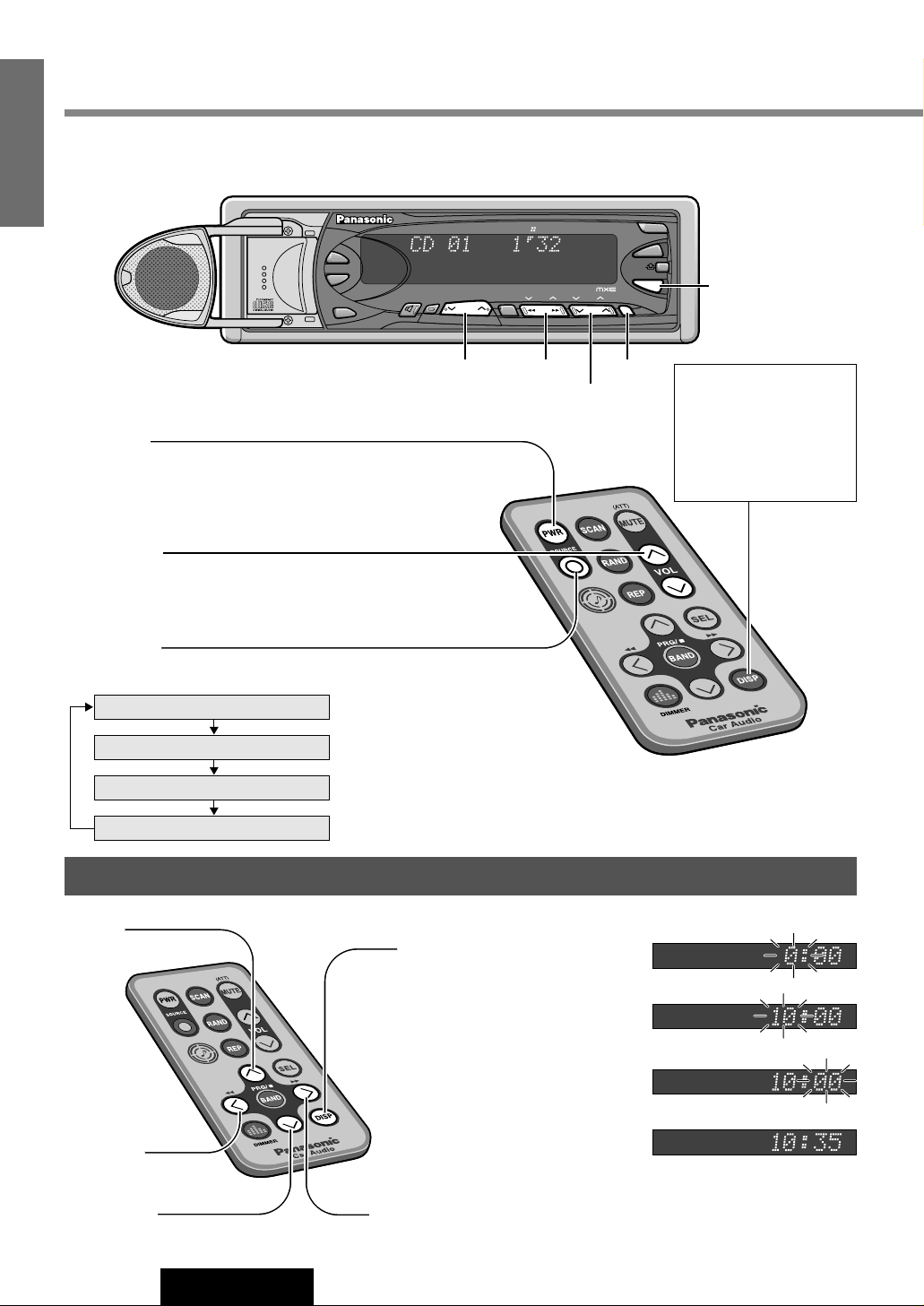
Clock Setting
This manual focuses on remote control operations. For functions not controlled from the remote controller, the manual
describes how to use the buttons on the main unit.
q
Press and hold [DISP] for
more than 2 seconds.
w
Press []] : Hour adjustment
[}] : Advance [{] : Back
e
Press [[] : Minute adjustment
[}] : Advance [{] : Back
r
Press [DISP] : end
Power
Turn the key in the ignition until the accessory indicator lights.
On : Press [PWR].
Off : Press again.
Volume
[}] : Up
[{] : Down
Note: The sound level for each source is
stored in memory.
Source
Press [SOURCE] to change the source.
12
CQ-DRX901U
2
E
N
G
L
I
S
H
Note : When the power
is switched on for the
first time, a demonstration message appears on
the display. To cancel
this display, press
[DISP] .
Note: The clock uses 12-hour system.
Page 9
Tilt 1
Tilt 2
Tilt 3
open
[DISP]
When the power is on
(Example: CD Player mode)
When the power is off
Regular Display
Dot Spectrum Analyzer Display
Clock Time Display
Clock Time Display
No Display
Because the following operations are not functioned with a remote control, use main unit buttons.
Display Change
Press [DISP] to change the display.
Note: Displays differ from each source mode.
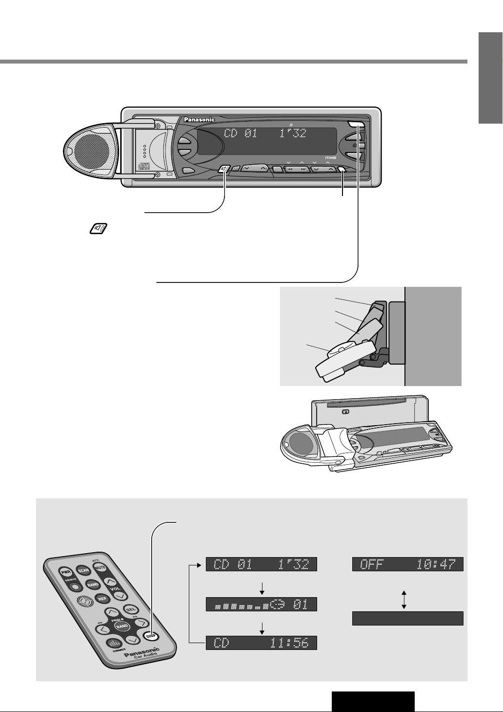
Open the
Center Speaker
Open : Press [].
Close : Press again.
Note: The center speaker can not be opened or closed
while the front panel is opened completely.
Panel Angle (Tilt)
Press and hold [OPEN] (TILT) for more than 1 second
until signal sound is heard, then release.
Each time the button is pressed for 1 second and
release it, the panel angle is changed (in 3 steps).
Open/Close the Front Panel
¡Press [OPEN] to open the front panel.
Note: If nothing is changed for 20 seconds, the original panel
position will be recovered.
¡To close the front panel completely, press [OPEN] again.
¡To recover the original panel position, press [OPEN] again
and hold it for more than 1 second, then release.
Notes:
¡When the ignition switch is turned OFF, the panel
and the center speaker are closed.
¡When the ignition switch is turned ON, the panel and the
center speaker are open to secure their former positions.
13
CQ-DRX901U
3
E
N
G
L
I
S
H
Caution: Watch that your fingers, others’ or especially
infants’ are not caught in the front panel when closing it.
CQ-DRX901U
CD RECEIVER WITH DSP & CHANGER CONTROL MOSFET
SPEAKER
OPEN/CLOSE
-
BAL/FAD
-
GEQ
MUTE
-
HEQ
-
POSI
S·A
DIMR
SUB·W
S-ANALYZER
DIMMER
SPC
OPEN
OPEN
DISC
45Wx4+5
DISP REMOTE
D
D
TILT
BAND
APM
POWER
SOURCE
Human Equalizer
SEL
TUNE P·SET
TRACK
VOL
Page 10
14
CQ-DRX901U
4
E
N
G
L
I
S
H
Radio
CQ-DRX901U
S-ANALYZER
DIMMER
TUNE P·SET
TILT
POWER
S·A
DIMR
SPC
SEL
TRACK
DISC
D
SUB·W
VOL
BAND
OPEN
SOURCE
CD RECEIVER WITH DSP & CHANGER CONTROL MOSFET
45Wx4+5
Human Equalizer
-
HEQ
-
POSI
-
BAL/FAD
-
GEQ
APM
MUTE
SPEAKER
OPEN/CLOSE
DISP REMOTE
D
BAND
SOURCE
TRACK
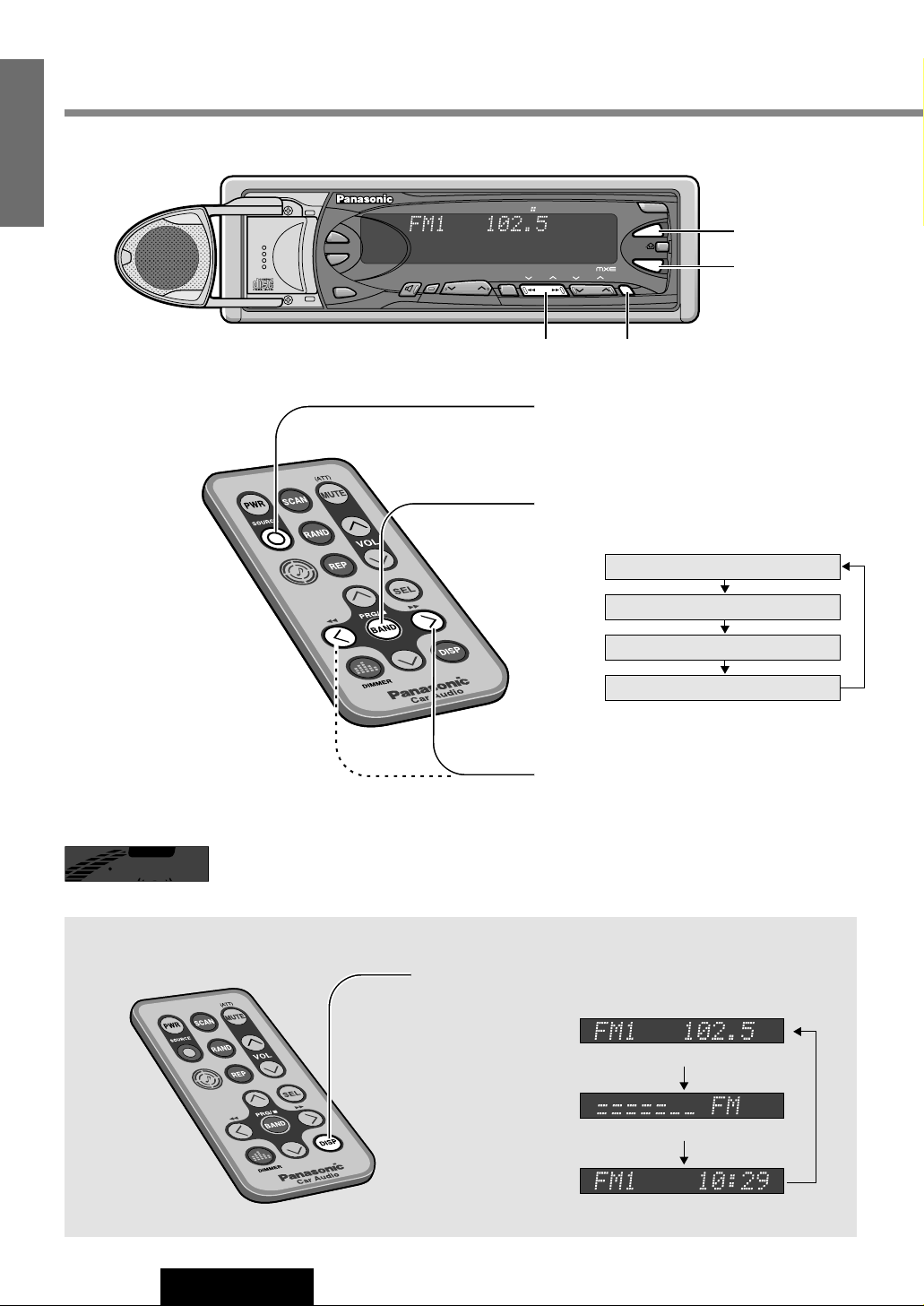
q
SOURCE
w
BAND
e
[]][[]
[DISP]
FM1
FM2
FM3
AM
STEREO
MUTE
Band Frequency
Regular Display
Dot Spectrum Analyzer Display
Clock Time Display
Display Change
Press [DISP] to change the display.
Radio Mode
Press [SOURCE] to change to radio
mode.
q
Band
Press [BAND].
w
Tuning
[[] : Up
[]] : Down
Press and hold [[] or []] for more
than 0.5 seconds, then release.
Seeking will start.
e
Note: The stereo indicator lights during reception of an
FM stereo broadcast.
Page 11
15
CQ-DRX901U
5
E
N
G
L
I
S
H
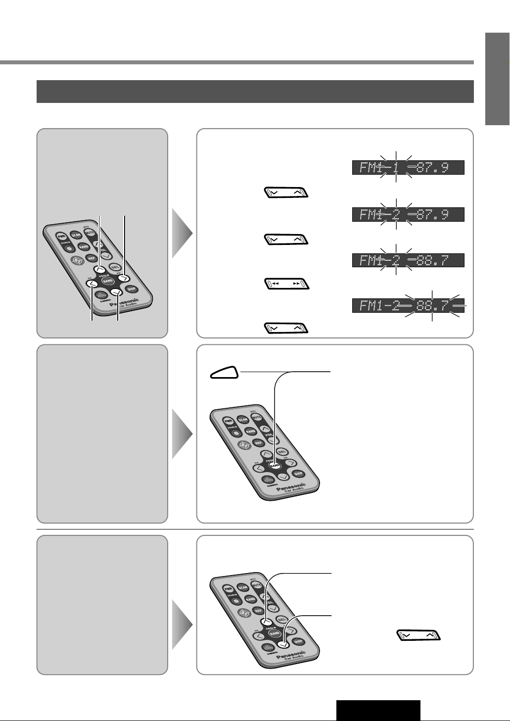
One-touch selection of a preset station
Up to 6 stations each can be saved in the FM1, FM2, FM3 and AM preset station memories.
Frequency Preset Number
Preset Number Frequency
Manual Preset
Memory
Manually save a station in the
preset memory.
Select a band (step q, w on the previous page)
q
w
e
r
Press and hold [}] or [{] for
more than 2 seconds.
Press [[] or []].
Press [}] or [{].
Press and hold [}] or [{] for
more than 2 seconds.
select a preset number
station frequency
blinks once
preset number blinks
Auto Preset
Memory
Automatically save strong
stations in the preset memory.
Select a band (step q, w on the previous page)
Press and hold [BAND] for more
than 2 seconds.
¡The 6 strongest available stations
will be automatically saved in the
memory under preset numbers 1
to 6.
¡Once set, the preset stations are
sequentially scanned for 5 seconds each.
¡To stop the scanning, press [}]
or [{].
Note: Any stations manually preset on the selected band will be deleted.
Preset Station
Calling
Select a band (step q, w on the previous page)
Press [}] to select the preset
number for tuning in the
preset station.
[{]: opposite direction
DISC
DISC
TRACK
DISC
BAND
DISC
Page 12
16
CQ-DRX901U
6
E
N
G
L
I
S
H
CD Player
Display Change
CQ-DRX901U
S-ANALYZER
DIMMER
TUNE P·SET
TILT
POWER
S·A
DIMR
SPC
SEL
TRACK
DISC
D
SUB·W
VOL
BAND
OPEN
SOURCE
CD RECEIVER WITH DSP & CHANGER CONTROL MOSFET
45Wx4+5
Hu
m
an E
qualizer
-
HEQ
-
POSI
-
BAL/FAD
-
GEQ
APM
MUTE
SPEAKER
OPEN/CLOSE
DISP REMOTE
D
OPEN
TRACK
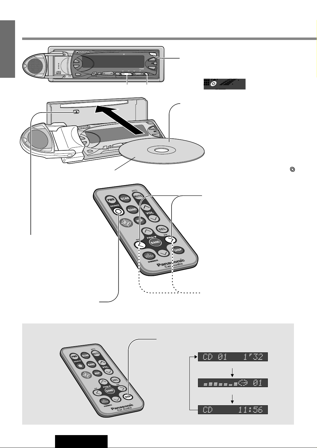
[DISP]
[1][2]
Label side
Track Number
Playing Time
Regular Display
Dot Spectrum Analyzer Display
Clock Time Display
Press [DISP] to change the display.
Open the front panel
Press [OPEN] on the front panel.
q
Disc Insert
The front panel closes automatically, and
then playback starts.
Note: Loading a CD when the power is
off allows the power to be turned on.
Cautions:
¡
Watch that your fingers, others’ or
especially infants’ are not caught in
the front panel when closing it.
¡
Make sure that the disc indicator ( )
is off before loading a disc. If the disc
indicator is on, eject the disc.
w
Track Selection
[2] : Next track.
[1] : Beginning of the current track.
Previous track. (Press twice)
Track Search
Press and hold
[2] : fast forward.
[1] : fast backward.
When CD is in the player
Press [SOURCE] to change to CD player
mode.
To eject the disc
¡Open the front panel.
Press [OPEN] on the front
panel.
¡press [u].
STE
When a CD is inside
Page 13
17
CQ-DRX901U
7
E
N
G
L
I
S
H
Various Way of Listening
(Only for remote control)
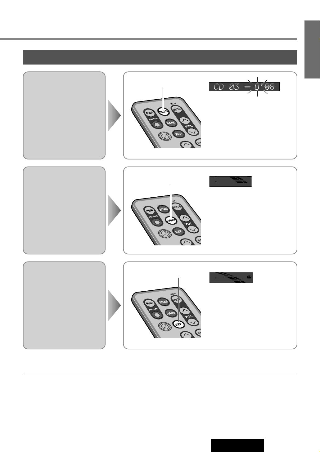
Scan Play
The first 10 seconds of each
track plays in sequence.
With the scanning of all tracks over,
the original program starts playing
from the beginning.
Press [SCAN] again to cancel.
Press [SCAN]
Random Play
All the available tracks are
played in a random sequence.
Press [RAND] again to cancel.
Repeat Play
Repeat the current selection.
Press [REP] again to cancel.
REP
RAND
REP
RAND
POSI
Cautions:
¡To avoid damaging the face plate, do not push it down or place objects on it while it is open.
¡Do not use irregularly shaped CDs (Heart-Shaped, Octagon, etc.).
Press [REP]
Press [RAND]
Page 14
18
CQ-DRX901U
8
E
N
G
L
I
S
H
CD Changer
CQ-DRX901U
S-ANALYZER
DIMMER
TUNE P·SET
TILT
POWER
S·A
DIMR
SPC
SEL
TRACK
DISC
D
SUB·W
VOL
BAND
OPEN
SOURCE
CD RECEIVER WITH DSP & CHANGER CONTROL MOSFET
45Wx4+5
Hum
a
n E
qualizer
-
HEQ
-
POSI
-
BAL/FAD
-
GEQ
APM
MUTE
SPEAKER
OPEN/CLOSE
DISP REMOTE
D
SOURCE
TRACK
DISC
[DISP]
e
[1][2]
w
[{][}]
q
[SOURCE]
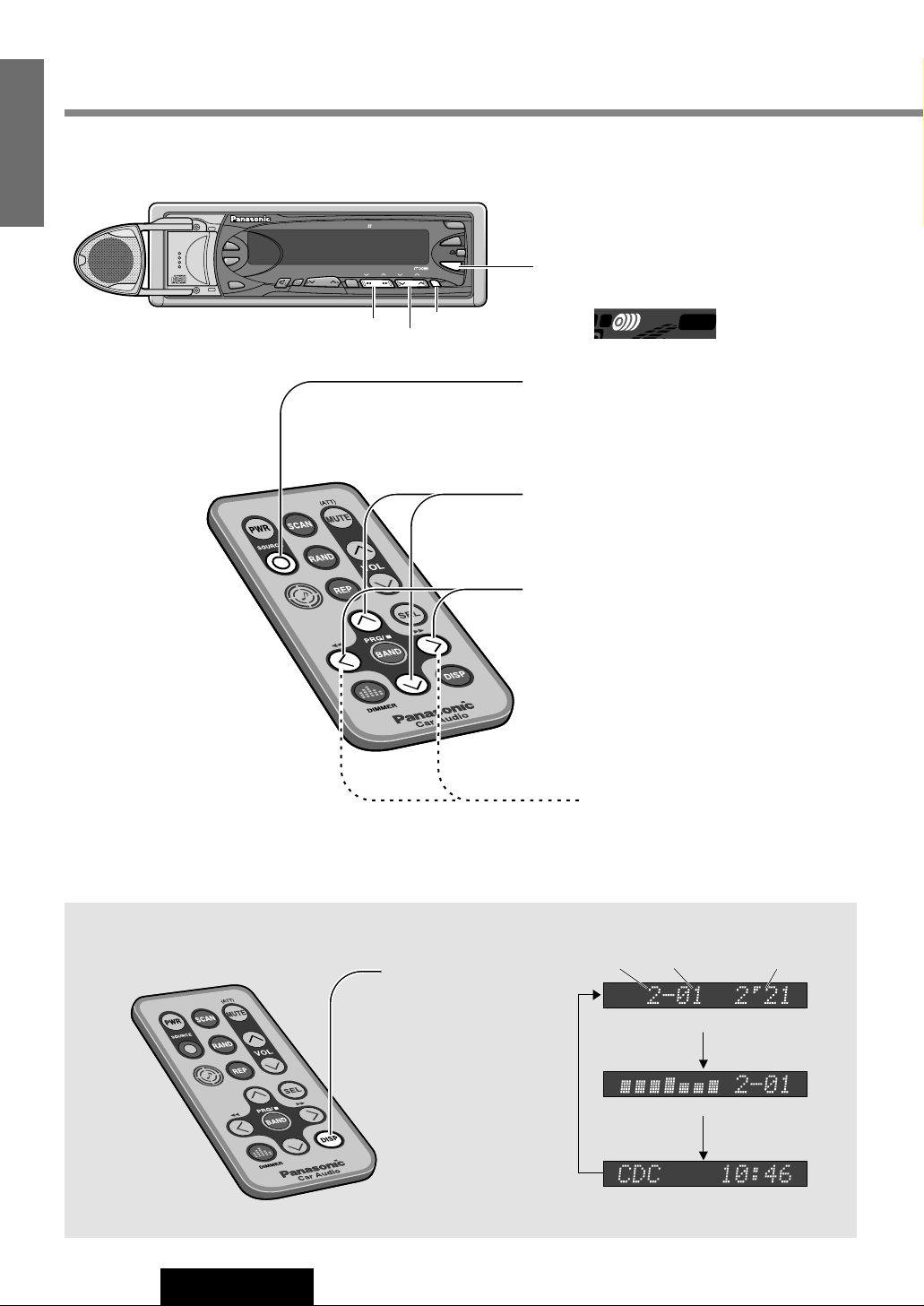
CD Changer Mode
Press [SOURCE] to change to CD
changer mode.
q
Disc Selection
[}] : Next disc.
[{] : Previous disc.
w
Track Selection
[2] : Next track.
[1] : Beginning of the current track.
Previous track. (Press twice)
e
Track Search
Press and hold
[2] : fast forward.
[1] : fast backward.
Display Change
Disc Number Playing TimeTrack Number
Regular Display
Dot Spectrum Analyzer
Clock Time Display
CD changer functions are designed for optional Panasonic CD changer unit.
Press [DISP] to
change the display.
When a CD changer
is connected
2
MUTE
Page 15

19
CQ-DRX901U
9
E
N
G
L
I
S
H
Various Way of Listening
(Only for remote control)
Track Scan
The first 10 seconds of each
track on the discs plays in
sequence.
Disc Scan
The first track of all the discs in
the magazine is played for 10
seconds each.
With the scanning of all tracks over,
the original program starts playing
from the beginning.
Press [SCAN] again to cancel.
With the scanning of all tracks over,
the original disc starts playing from
the beginning.
Press and hold [SCAN] again to
cancel.
Track Random
All the available tracks on all
discs in the magazine are played
in a random sequence.
Disc Random
All the available tracks on current
disc are played in a random
sequence.
Press [RAND] again to cancel.
Press and hold [RAND] again to
cancel.
Track Repeat
Repeat the current selection
Disc Repeat
Repeat the current disc selection
Press [REP] again to cancel.
Press and hold [REP] again to
cancel.
Press [SCAN]
Press and hold [SCAN]
for more than 2 seconds.
REP
RAND
REP
RAND
REP
RAND
POSI
REP
RAND
POSI
Press [RAND]
Press [REP]
Press and hold [RAND]
for more than 2 seconds.
Press and hold [REP]
for more than 2 seconds.
Page 16

20
CQ-DRX901U
10
E
N
G
L
I
S
H
Useful Functions
q
w
q
Press
and hold
w
Press
Mute
(ATT)
CQ-DRX901U
S-ANALYZER
DIMMER
TUNE P·SET
TILT
POWER
S·A
DIMR
SPC
SEL
TRACK
DISC
D
SUB·W
VOL
BAND
OPEN
SOURCE
CD RECEIVER WITH DSP & CHANGER CONTROL MOSFET
45Wx4+5
H
um
an E
qualize
r
-
HEQ
-
POSI
-
BAL/FAD
-
GEQ
APM
MUTE
SPEAKER
OPEN/CLOSE
DISP REMOTE
S·A
DIMR
TRACK
Dimmer qw
MUTE(ATT)
Spectrum Analyzer
qw
Spectrum Analyzer
Display
Default : WAVE
Variety : 11 types
Display Brightness
Setting range
(Dimmer)
Default:
When car lights are on : DIMMER LEV 2
When car lights are off : DIMMER LEV 3
Setting range: LEV 1 to LEV 3
Volume Down
(Mute/Attenuator)
The volume is reduced or muted
depending on whether you select
Mute or ATT. (a page 30)
Default : MUTE (off)
Page 17

21
CQ-DRX901U
11
E
N
G
L
I
S
H
q Press []/ [S·A]
SPEANA SEL
w Press [[] to change the Spectrum Analyzer display.
( []] : opposite direction)
WAVE, AURORA, c, BLANK SPEANA, ALL DISP OFF, etc.
Note :
Turns off all display contents.
(The display turns on when a button is
operated, and goes off 5 seconds after
the last operation.)
ALL DISP OFF
Turns off the Spectrum
Analyzer display only.
BLANK SPEANA
q Press and hold
[](DIMMER) / [DIMR]
for more than 2 seconds.
DIMMER SEL
w Press [](DIMMER) to change the dimmer level as follows.
DIMMER LEV 3 ccccc Brighter
DIMMER LEV 2 ccccc Medium
DIMMER LEV 1 ccccc Darker
Press [MUTE] (ATT) to switch the MUTE mode (ATT mode) between on and off.
MUTE off ccccc Regular volume level
MUTE on ccccc No sound
ATT off cccccc Regular volume level
ATT on cccccc Decrease the volume to
1/10 of previous level.
When ATT is set
When MUTE is set
Page 18

22
CQ-DRX901U
12
E
N
G
L
I
S
H
Sound Settings and Sound Space
q
Press [SEL] to
selection an
operation
CQ-DRX901U
S-ANALYZER
DIMMER
TUNE P·SET
TILT
POWER
S·A
DIMR
SPC
SEL
TRACK
DISC
D
SUB·W
VOL
BAND
OPEN
SOURCE
CD RECEIVER WITH DSP & CHANGER CONTROL MOSFET
45Wx4+5
H
um
an E
qualize
r
-
HEQ
-
POSI
-
BAL/FAD
-
GEQ
APM
MUTE
SPEAKER
OPEN/CLOSE
DISP REMOTE
SEL
TRACK
DISC
w [
{][}
]
w [
]][[
]
q [SEL]
w
Set
Regular Mode
HUMAN EQ
GRAPHIC EQ
BAL//FAD
POSITION SEL
SUPER BASS
SDBB SELECT
CENTER LEVEL
Tone Quality
(Human Equalizer/HEQ)
There are 49 ready patterns to make presetting
easier.
Default : FLAT(0)
Setting range : 1 - 3 for each patterns
(49 patterns)
Saving your Tone
Quality Preferences
(Graphic Equalizer/GEQ)
You can adjust the level from bass to treble in
each of 7 frequency bands. Up to 5 tone quality
preferences can be saved in memory (preset
memory 1 to 5).
Default : 0 for each frequency
Setting range : –12 to +12 in 2 dB - steps
Page 19

23
CQ-DRX901U
13
E
N
G
L
I
S
H
q
Press [SEL]
w
Set
Select
HUMAN EQ
[}] : Heavy bass
[
{] : Light bass
[
[] : Sharp treble
[
]] : Soft treble
Select
GRAPHIC EQ
To recall a preset tone
quality, press [
}] to
select one of the
preset numbers
1 - 5.
( [
{] : opposite
direction)
After selecting one of the preset numbers 1 - 5,
q Press and hold [SEL] for more then 2 seconds to
change to graphic equalizer preset mode.
w Adjust the level for each frequency.
Press [
[] to change the frequency.
80 ➝ 160 ➝ 320 ➝ 640 ➝ 1.6k ➝ 4k ➝ 10k (Hz)
( [
]] : opposite direction)
[
}] : Upper level
[
{] : Lower level
e Press [SEL] to save the level.
A tone quality that excludes blurred bass and is
comfortable to listen to is already saved under preset
number 6.
To select preset number 6, press [
}] or [{].
Note: You cannot save under preset number 6.
Recalling the Recommended Tone Quality
Memorize
E
Recreation
E
Enjoyable drive
E
Calm down
E
Concentration
E
Safe driving
E
Relieve stress
E
Refresh
E
Listen to the music
E
Rhythmical
E
Wake up
Heavy
Light
Sharp
Soft
Notes:
¡If no keys have been pressed for more than 10 seconds, the
display returns to the previous one after changing to the menu
display.
¡The indicator will light up, whenever each setting is set to a
value other than default.
EQ
EQ
Page 20

24
CQ-DRX901U
14
E
N
G
L
I
S
H
Sound Settings and Sound Space(continued)
q
Press [SEL] to
selection an
operation
CQ-DRX901U
S-ANALYZER
DIMMER
TUNE P·SET
TILT
POWER
S·A
DIMR
SPC
SEL
TRACK
DISC
D
SUB·W
VOL
BAND
OPEN
SOURCE
CD RECEIVER WITH DSP & CHANGER CONTROL MOSFET
45Wx4+5
H
um
an
Equa
lizer
-
HEQ
-
POSI
-
BAL/FAD
-
GEQ
APM
MUTE
SPEAKER
OPEN/CLOSE
DISP REMOTE
SEL
TRACK
DISC
w [
{][}
]
w [
]][[
]
q [SEL]
w
Set
Regular Mode
HUMAN EQ
GRAPHIC EQ
BAL//FAD
POSITION SEL
SUPER BASS
SDBB SELECT
CENTER LEVEL
Balance and Fader
(Balance/Fader)
You can adjust the sound balance among
the front, rear, right and left speakers.
Default : B(Balance) : CNT(Center)
F(Fader) : CNT(Center)
Setting range : 15 levels each
Sound Image
(Position)
You can adjust the sound image in
accordance with the listener’s position.
Default : Off
Rear Speakers as Sub-Woofers
(Super Bass Control Sub-Woofer/SBC-SW)
You can utilize the rear speakers connected to
the built-in amplifier as Sub-Woofers that
output only bass.
Default : Off
Bass Enhancement
(Super Dynamic Bass Boost/SDBB)
The bass of the 4 speakers connected to the
built-in amplifier is enhanced, so that you can
enjoy a heavy bass sound.
Default : Off
Page 21

25
CQ-DRX901U
15
E
N
G
L
I
S
H
q
Press [SEL]
w
Set
Select
BAL//FAD
[}] : Front enhanced
[{] : Rear enhanced
[[] : Right enhanced
[]] : Left enhanced
Select
POSITION SEL
Press [[] to change as follows. ([]] : opposite direction)
OFF cccccccc All seats
RIGHT cccccc Front right
LEFT ccccccc Front left
FRONT cccccc Front
REAR ccccccc Rear
Select
SUPER BASS
[[] : On cBass Enhancement (Monaural)
[]] : Off cRegular Output (Stereo)
¡Adjust the Sub-Woofer output level (a page 28)
It is also interlocked with the preout (rear speaker output).
¡BAL/FAD, POSITION, SDBB and Space settings for rear speaker output
will be invalid.
SBC-SW ON
Select
SDBB SELECT
Press [[] to change output as follows. ([]] : opposite direction)
SDBB Off ccc Normal output
SDBB Type1cc Variable, low
SDBB Type2cc Variable, high
SDBB Type3cc Fixed, low
SDBB Type4cc Fixed, high
¡Variable : Bass enhancement
along with the volume
¡Fixed : Bass enhancement within
fixed range
dB
12
8
0
300Hz
OFF
Frequency
TYPE1 iVariable: lowj
TYPE2 iVariable: highj
TYPE3 iFixed: lowj
TYPE4 iFixed: highj
Boost pressur
Notes:
¡If no keys have been pressed for more than 10 seconds, the
display returns to the previous one after changing to the menu
display.
¡The indicator will light up, whenever each setting is set to a
value other than default.
POSI
Page 22

26
CQ-DRX901U
16
E
N
G
L
I
S
H
Sound Settings and Sound Space(continued)
q
Press [SEL] to
select
CENTER LEVEL
CQ-DRX901U
S-ANALYZER
DIMMER
TUNE P·SET
TILT
POWER
S·A
DIMR
SPC
SEL
TRACK
DISC
D
SUB·W
VOL
BAND
OPEN
SOURCE
CD RECEIVER WITH DSP & CHANGER CONTROL MOSFET
45Wx4+5
H
um
an
Equa
lizer
-
HEQ
-
POSI
-
BAL/FAD
-
GEQ
APM
MUTE
SPEAKER
OPEN/CLOSE
DISP REMOTE
SEL
TRACK
DISC
e [
{][}
]
w [
]][[
]
q [SEL]
e
Set
Select
CENTER LEVEL
Select
CENTER DELAY
DownUp
Regular Mode
HUMAN EQ
GRAPHIC EQ
BAL//FAD
SUPER BASS
SDBB SELECT
CENTER LEVEL
POSITION SEL
Center Speaker Output
The sound image is raised and oriented in
the front center.
Adjust the Center
Speaker Volume
(Center Speaker Volume Level)
Default : 0
Setting range : - , –10 to +10
in 2 dB - steps
Adjust the Sense of
Distance
(Center Speaker Delay Time)
Default : 0
Setting range : –10 to +10
(1 step = 0.0003 seconds)
w
Adjust the center speaker and sound space
exactly by the following steps in order to make
full use of the sound space function.
Page 23

27
CQ-DRX901U
17
E
N
G
L
I
S
H
Select
CENTER LEVEL
Adjustment Procedure
Open the center speaker. (a page 13)
1. Adjust the center speaker volume.
Adjust the volume so that middle tone such as vocal is oriented toward
the front center without adding DSP effect to the center speaker. (Center
speaker delay time : 0, sound space : Space off)
2. Adjust the sound space and the center speaker delay time.
3. Adjust the center speaker volume again.
Adjust the volume to suit the sound space setting.
Press [[] to select
CENTER LEVEL
[}] : Up
[
{] : Down
- : No sound from the center speaker
Press []] to select
CENTER DELAY
[}] : Longer delay time, farther sound image
(center speaker output timing is delayed)
[
{] : Shorter delay time, closer sound image.
(center speaker output timing is advanced)
0 : The output timing of the center speaker is synchronized with that
of the other speakers.
q
Press [SEL]
w
Press []] or [[]
e
Set : Press [}] or [{]
Note: If no keys have been pressed for more than 10 seconds,
the display returns to the previous one after changing to the
menu display.
Page 24

28
CQ-DRX901U
18
E
N
G
L
I
S
H
Sound Settings and Sound Space(continued)
q
Press [ ]
w
Select
CQ-DRX901U
S-ANALYZER
DIMMER
TUNE P·SET
TILT
POWER
S·A
DIMR
SPC
SEL
TRACK
DISC
D
SUB·W
VOL
BAND
OPEN
SOURCE
CD RECEIVER WITH DSP & CHANGER CONTROL MOSFET
45Wx4+5
Hu
m
an E
q
u
alizer
-
HEQ
-
POSI
-
BAL/FAD
-
GEQ
APM
MUTE
SPEAKER
OPEN/CLOSE
DISP REMOTE
SPC
TRACK
DISC
e [
{][}
]w [
]][[
]q
q
Press and hold [ ] (Space)
for more than 2 seconds.
w
Press []] or [[] to
select an operation
e
Set
This adjustment is effective when Sub-woofers are connected or when the rear speakers are used as Sub-Woofers.
(
a page 24)
Sub-Woofer Output
(Digital Dynamic Bass Control/DDBC)
Sound Space
Reproduction
(Space)
Concert hall presence in your car
Default : Off
Sub-Woofer Volume
(DDBC Volume Level)
Default : 0
Setting range : - , –10 to +10
in 2 dB - steps
Sense of Distance
(DDBC Delay Time)
There is no delay time between speaker and
Sub-Woofer sound, so that you can enjoy
dynamic heavy bass.
Default : 0
Setting range : –10 to +10
1 step = 0.0003 seconds
Bass Control
(DDBC Cutoff Frequency)
The upper limit of the bass cutoff frequency is
controlled, so that you can enjoy a clearer
sound.
Default : OFF
Page 25

29
CQ-DRX901U
19
E
N
G
L
I
S
H
Press []/ [SPC] to change to
Space mode.
SPACE OFF
Press [[] to change space as follows. ([]] : opposite direction)
SPACE OFF STADIUM
CONCERT HALL VOCAL
Note: The space setting for each source is stored in memory.
Select
DDBC LEVEL
[}] : Up
[{] : Down
- : No Sub-Woofer sound
Select
DDBC DELAY
[}] : Delay time longer (Sub-Woofer output timing is delayed.)
[{] : Delay time shorter (Sub-Woofer output timing is advanced.)
0 : The output timing of the Sub-Woofer is synchronized with that of
the other speakers.
Select
FREQ. SELECT
Press [}] to change the cutoff frequency. ([{] : opposite direction)
OFF 100 150 200 (Hz)
OFF : Regular output, high tone included
w
Press []] or [[]
e
Set : Press [}] or [{]
Notes:
¡If no keys have been pressed for more than 10 seconds, the display returns to the previous one after changing to the
menu display.
¡The indicator will light up, whenever each setting is set to a value other than default.
H
H
H
SPACE
SPACE
SUB.W
SUB.W
T
T
DELAY
SUB.W
T
Page 26

30
CQ-DRX901U
20
E
N
G
L
I
S
H
Other Settings
CQ-DRX901U
S-ANALYZER
DIMMER
TUNE P·SET
TILT
POWER
S·A
DIMR
SPC
SEL
TRACK
DISC
D
SUB·W
VOL
BAND
OPEN
SOURCE
CD RECEIVER WITH DSP & CHANGER CONTROL MOSFET
45Wx4+5
Hu
m
an
Eq
ualiz
er
-
HEQ
-
POSI
-
BAL/FAD
-
GEQ
APM
MUTE
SPEAKER
OPEN/CLOSE
DISP REMOTE
SEL
TRACK
DISC
e [
]][[
]qw
[SEL]
e
Set
q
Press and hold
[SEL] for more than
2 seconds
w
Press [SEL] to select
an operation
SIGNAL SEL
MUTING SEL
SPEANA SPEED
MUTE KEY SEL
CONTRAST SEL
AUX IN SET
S-LED SEL
TILT SELECT
Key Tone
(Signal/beep sound)
You can select a Key tone that comes from the
center speaker when pressing the buttons and
adjust the volume.
Default : SIGNAL SOUND
SIGNAL Level 3
Navi Mute (in future use)
Allows you to mute the current source while
your navigation system provides voice
guidance.
Default : MUTING ON
Spectrum Analyzer
Speed
Default : SPEANA FAST
Mute/ATT(Attenuator)
Default : MUTE KEY
e [
{][}
]
Page 27

31
CQ-DRX901U
21
E
N
G
L
I
S
H
Select
SIGNAL SEL
No sound
SIGNAL OFF
Beep
SIGNAL BEEP
Sound varies
with operation
SIGNAL SOUND
[}] : Up
[
{] : Down
(Setting range : Level 1 to Level 3)
Volume
Select
MUTING SEL
While navigation voice guidance is active.
No sound
Decreased to half
Unchanged
Note: “MUTING ****” is displayed (for MUTING ON or HALF)
MUTING OFF
MUTING HALF
MUTING ON
Select
SPEANA SPEED
Faster
Slower
SPEANA SLOW
SPEANA FAST
Select
MUTE KEY SEL
When [MUTE] is pressed
No sound
Decreased to 1/10
ATT KEY
MUTE KEY
w
Press [SEL]
e
Press []] or [[] / [{] or [}]
Note: If no keys have been pressed for more than 10 seconds, the display
returns to the previous one after changing to the menu display.
Page 28

32
CQ-DRX901U
22
E
N
G
L
I
S
H
Other Settings(continued)
CQ-DRX901U
S-ANALYZER
DIMMER
TUNE P·SET
TILT
POWER
S·A
DIMR
SPC
SEL
TRACK
DISC
D
SUB·W
VOL
BAND
OPEN
SOURCE
CD RECEIVER WITH DSP & CHANGER CONTROL MOSFET
45Wx4+5
H
um
an Equ
alize
r
-
HEQ
-
POSI
-
BAL/FAD
-
GEQ
APM
MUTE
SPEAKER
OPEN/CLOSE
DISP REMOTE
SEL
TRACK
e [
]][[
]qw
[SEL]
e
Set
q
Press and hold
[SEL] for more than
2 seconds
w
Press [SEL] to select
an operation
Up/OnDown/Off
SIGNAL SEL
MUTING SEL
SPEANA SPEED
MUTE KEY SEL
CONTRAST SEL
AUX IN SET
S-LED SEL
TILT SELECT
Contrast
Allows you to adjust the display contrast for
better viewing.
Default : Level 3
Setting range : Level 1 to Level 5
Excluding AUX-IN from
source Selection
AUX will be excluded from the selection.
Default : On
Security Indicator
The security indicator blinks while the removable
face plate is removed from this unit.
Default : On
Panel Angle
(Tilt On/Off)
(a page 13 about tilt angle)
Default : Tilt on
Page 29

33
CQ-DRX901U
23
E
N
G
L
I
S
H
Select
CONTRAST SEL
[[] : Up
[]] : Down
Select a level for easy viewing.
Select
AUX-IN SET
[[] : AUX-IN On External input (AUX-IN) is selectable as a source.
[]] : AUX-IN Off External input (AUX-IN) is not selectable as a
source.
With AUX-IN set to OFF, AUX-IN will not be selected when [SOURCE] is
pressed. (a page 12 about source selection)
Select
S-LED SEL
[[] : S-LED On The indicator blinks when the panel is removed.
[]] : S-LED Off The indicator does not blink when the panel is
removed.
Select
TILT SELECT
[[] : TILT On Panel angle can be adjusted.
[]] : TILT Off Panel angle cannot be adjusted.
w
Press [SEL]
e
Press []] or [[]
Note: If no keys have been pressed for more than 10 seconds, the display
returns to the previous one after changing to the menu display.
Page 30

34
CQ-DRX901U
24
E
N
G
L
I
S
H
Installation Guide
WARNING
This installation information is designed for experienced installers
and is not intended for non-technical individuals. It does not contain
warnings or cautions of potential dangers involved in attempting to
install this product.
Any attempt to install this product in a motor car by anyone other
than qualified installer could cause damage to the electrical system
and could result in serious personal injury or death.
❏ Overview
This product should be installed by a professional.
However, if you plan to install this product yourself,
your first step is to decide where to install it. The
instructions in these pages will guide you through
the remaining steps: (Please refer to the “WARN-
ING” statement above).
¡Identify and label the car wires.
¡Connect the car wires to the wires of the power
connector.
¡Install the unit in the dash.
¡Check the operation of the unit.
If you encounter problems, please consult your
nearest professional installer.
Caution: This unit operates with a 12 volt DC negative ground auto battery system only. Do not attempt
to use it in any other system. Doing so could cause
serious damage.
Before you begin installation, look for the items on
the right which are packed with your unit.
¡Warranty Card....................Fill this out promptly.
¡Panasonic Service center for Service
Directory.............................Keep for future refer-
ence in case the product needs servicing.
¡Installation Hardware........Needed for in-dash
installation.
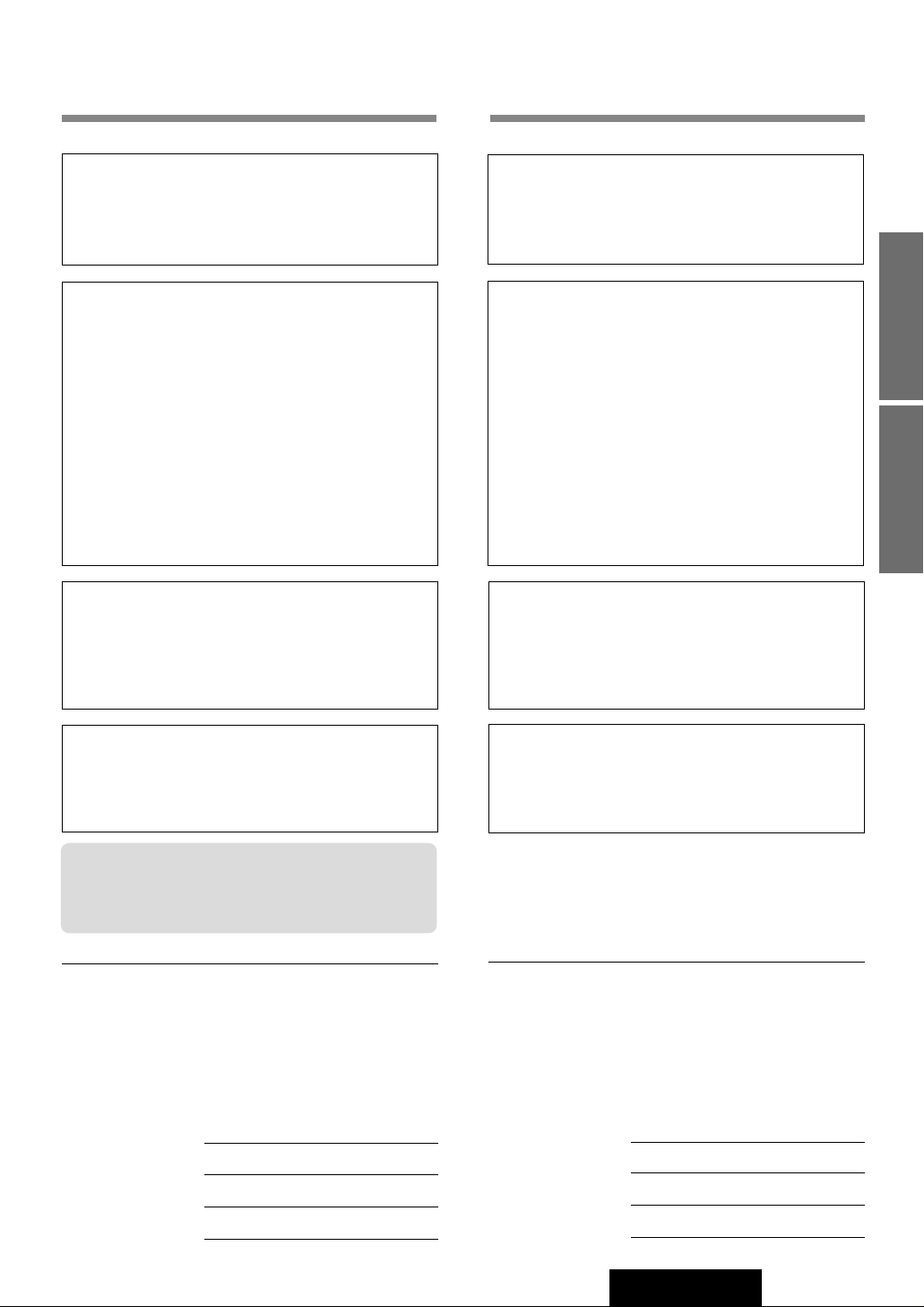
❏ Installation Hardware
❏ Required Tools
You’ll need a screwdriver, a 1.5 volt AA battery, and
the following:
q 1
w 1
e 1
r 1
t 1
y 1
u 1
i 1
Mounting Collar
Mounting Bolt (5 mmø)
Power Connector
Removable Face Plate Case
Trim Plate
Rear support strap
Tapping screw
Hex. Nut
No. Item
Diagram
Q’ty
12 V DC
Test Bulb
Electrical
Tape
Side-Cut
Pliers
Page 31

35
CQ-DRX901U
25
E
N
G
L
I
S
H
❏ Dashboard Specifications
❏ Identify All Leads
The first step in installation is to identify all the car
wires you’ll use when hooking up your sound system.
As you identify each wire, we suggest that you label
it using masking tape and a permanent marker. This
will help avoid confusion when making connections
later.
Note: Do not connect the power connector to the
stereo unit until you have made all connections. If
there are no plastic caps on the stereo hooking
wires, insulate all exposed leads with electrical tape
until you are ready to use them. Identify the leads in
the following order.
Power Lead
If your car has a radio or is pre-wired for one :
Cut the connector wires one at a time from the plug
(leaving the leads as long as possible) so that you
can work with individual leads.
Turn the ignition on to the accessory position, and
ground one lead of the test bulb to the chassis.
Touch the other lead of the test bulb to each of the
exposed wires from the cut radio connector plug.
Touch one wire at a time until you find the outlet that
causes the test bulb to light.
Now turn the ignition off and then on. If the bulb also
turns off and on, that outlet is the car power lead.
If your car is not wired for an audio unit :
Go to the fuse block and find the fuse port for radio
(RADIO), accessory (ACC), or ignition (IGN).
Thickness
Min. 3/16" (4.75 mm)
Max. 7/32" (5.56 mm)
7-5/32" (182 mm)
2-3/32" (53 mm)
Battery Lead
If your stereo unit has a yellow lead, you will need to
locate the car's battery lead. Otherwise you may
ignore this procedure. (The yellow battery lead provides continuous power to maintain a clock, memory
storage, or other function.)
If your car has a radio or is pre-wired for one:
With the ignition and headlights off, identify the car
battery lead by grounding one lead of the test bulb
to the chassis and checking the remaining exposed
wires from the cut radio connector plug.
If your car is not wired for an audio unit :
Go to the fuse block and find the fuse port for the
battery, usually marked BAT.
Speakers
Identify the car speaker leads. There will be two
leads for each speaker, usually color coded.
A handy way to identify the speaker leads and the
speaker they connect with is to test the leads using
a 1.5 V AA battery as follows.
Hold one lead against one pole of the battery and
stroke the other lead across the other pole. You will
hear a scraping sound in a speaker if you are holding a speaker lead.
If not, keep testing different lead combinations until
you have located all the speaker leads. When you
label them, include the speaker location for each.
Antenna Motor
If your car is equipped with an automatic power
antenna, identify the car motor antenna lead by connecting one bulb tester lead to the car battery lead
and touching the remaining exposed wires from the
cut radio connector plug one at a time. You will hear
the antenna motor activate when you touch the correct wire.
Antenna
The antenna lead is a thick, black wire with a metal
plug at the end.
❏ Connect All Leads
Now that you have identified all the wires in the car,
you're ready to begin connecting them to the stereo
unit wires. The connection diagram (B Page 40)
shows the proper connections and color coding of
the leads.
We strongly recommend that you test the unit
before making a final installation.
You can set the unit on the floor and make temporary connections to test the unit. Use electrical tape
to cover all exposed wires.
Page 32

36
CQ-DRX901U
26
E
N
G
L
I
S
H
Important: Connect the red power lead last, after
you have made and insulated all other connections.
Ground
Connect the black ground lead of the power connector to the metal car chassis.
Speakers
Connect the speaker wires. See the wiring diagram
for the proper hookups. Follow the diagram carefully
to avoid damaging the speakers and the stereo unit.
The speaker used must be able to handle more than
45 W of audio power. If using an optional audio
power, the speakers should be able to handle the
maximum amplifier output power. Speakers with low
input ratings can be damaged.
Speaker impedance should measure 4 - 8 Ω, which
is typically marked on most speakers. Lower or
higher impedance speakers will affect output and
can cause both speaker and stereo unit damage.
Caution: Never ground the speaker cords. For
example, do not use a chassis ground system or a
three-wire speaker common system. Each speaker
must be connected separately using parallel insulated wires. If in doubt about how your car's speakers
are wired, please consult with your nearest professional installer
Motor Antenna
Connect the car motor antenna lead to the blue
motor antenna relay control lead.
Battery
Connect the yellow battery lead to the correct radio
wire or to the battery fuse port on the fuse block.
Antenna
Connect the antenna by plugging the antenna lead
into the antenna receptacle.
Equipment
Connect any optional equipment such as an amplifier, according to the instructions furnished with the
equipment. Leave about 12 inches (30 cm) of distance between the speaker cords/amplifier unit and
the antenna/antenna extension cord. Read the operating and installation instructions of any equipment
you will connect to this unit.
Power
Connect the red power lead to the correct car radio
wire or to the appropriate fuse port on the fuse
block.
If the stereo unit functions properly with all these
connections made, disconnect the wires and proceed to the final installation.
❏ Final Installation
Lead Connections
Connect all wires, making sure that each connection
is insulated and secure. Bundle all loose wires and
fasten them with tape so they won't fall down later.
Now insert the stereo unit into the mounting collar.
Congratulations! After making a few final checks,
you’re ready to enjoy your new auto stereo system.
❏ Final Checks
1. Make sure that all wires are properly connected and insulated.
2. Make sure that the stereo unit is securely held
in the mounting collar.
3. Turn on the ignition to check the unit for proper operation.
If you have difficulties, consult your nearest authorized professional installer for assistance.
❏ Precautions
Installation Guide (continued)
¡We strongly recommend that you wear gloves
for installation work to protect yourself from
injuries.
¡When bending the mounting tab of the mount-
ing collar with a screwdriver, be careful not to
injure your hands and fingers.
Caution: Do not disconnect the battery terminals
of a car with trip or navigational computer since
all user settings stored in memory will be lost.
Instead take extra care with installing the unit to
prevent shorts.
¡Disconnect the cable from the negative (
-
) battery
terminal (see caution below).
¡Unit should be installed in a horizontal position
with the front end up at a convenient angle, but
not more than 30°.
less than 30°
Page 33

1
2
3
4
Insert Mounting Collar q into the dashboard,
and bend the mounting tabs out with a
screwdriver.
Secure the rear of the unit.
After fixing Mounting Bolt w and Power Connector e,
fix the rear of the unit to the car body by either method
(a) or (b) shown below.
Insert Trim Plate t.
After installation
reconnect the
negative (
-
) battery
terminal.
Lock Lever (C)
Power Connector e
Mounting Tabs
Mounting Bolt w
(a) Using the Rear Support Strap y
Fire Wall of Car
iHex. Nut
yRear Support Strap
wMounting Bolt
qMounting Collar
uTapping Screw
3 mmø
Rubber Cushion
(Option)
wMounting Bolt
qMounting Collar
Rear Support Bracket
(Provided on the car)
(b) Using the Rubber Cushion (Option)
Make sure that the lock lever (C)
is flush with the mounting collar
(not projecting outward).
Lock Lever
37
CQ-DRX901U
27
E
N
G
L
I
S
H
❏ Installation Procedures
Page 34

38
CQ-DRX901U
28
E
N
G
L
I
S
H
Installation Guide (continued)
To Remove the Unit
q Remove the removable face plate.
(a) Switch off the power
of the unit.
(b)
Press the release
button [ ].
(c) Pull on the right side of the unit.
w Remove the trim plate t with a screwdriver.
e Pull out the unit while pushing down the lock
lever with a screwdriver.
r Remove the unit pulling with both hands.
TILT
POWER
BAND
OPEN
SOURCE
MOSFET
45Wx4+5
APM
Cautions:
¡Do not touch the contacts on the face plate or on the main unit, since this may result in poor electrical contacts.
¡If dirt or other foreign substances get on the contacts, wipe them off with clean and dry cloth.
Main Unit
w
q
Contact
tTrim Plate
Screwdriver
1
2
Lock Lever
Screwdriver
Lock
Lever
Page 35

39
CQ-DRX901U
29
E
N
G
L
I
S
H
Anti-Theft System
This unit is equipped with a removable face plate. Removing
this face plate makes the radio totally inoperable.
The security indicator will blink.
Place Removable Face Plate
into Case
q Switch off the power of the unit.
w Remove the removable face plate.
(a Page 38)
e Gently press the bottom of the case and open the cover.
Place the face plate into the case and take it with you
when you leave the car.
Install Removable Face Plate
q Slide the left side of the removable face plate in place.
w Press the right end of removable face plate until “click”
is heard.
Security Indicator
The security indicator blinks when the removable face plate
is removed from the unit. (a Page 32)
q Press and hold [SEL] for more than 2 seconds to
change to function control mode.
w Press [SEL] to select “S-LED SEL”.
e Press [[] to turn the security indicator (S-LED) on.
( []] : off)
Cautions:
¡This face plate is not water-proof. Do not expose it to water or excessive moisture.
¡Do not remove the face plate while driving your car.
¡Do not place the face plate on the dashboard or nearby areas where the temperature rises to high levels.
Display
Security
Indicator
Blinks
OFF
r Removable Face Plate Case
q
CQ-DRX901U
S-ANALYZER
S·A
DIMR
DIMMER
SPEAKER
OPEN/CLOSE
-
HEQ
-
BAL/FAD
SUB·W
-
POSI
-
GEQ
SPC
CD RECEIVER WITH DSP & CHANGER CONTROL MOSFET
MUTE
H
um
an
E
q
ualize
r
TUNE P·SET
VOL
SEL
TRACK
w
OPEN
45Wx4+5
TILT
BAND
APM
POWER
SOURCE
DISP REMOTE
D
DISC
Security
Indicator
Page 36

40
CQ-DRX901U
30
E
N
G
L
I
S
H
Electrical Connections
AUX-IN
CH.C-IN
FRONT
REAR
S·W-OUT
(L)(White)
(R)(Red)
(L)(White)
(R)(Red)
(White)
(Red)
(L)(White)
(R)(Red)
(L)(White)
(R)(Red)
Pre-out Cord (Front)
Pre-out Cord (Rear)
Sub-Woofer Cord
(Monaural)
AUX Input Cord
CD Changer Input Cord
CQ-DRX901U
Antenna
ePower Connector
CD Changer
Connector
Navi Mute Lead (in future use)
External Amplifier Control Power Lead
(Blue w/white stripe)
Connect to the Navi Mute Lead of the Panasonic
car navigation system.
Note: Keep the orange cap covered for insulation
if this lead is not used.
Battery Lead
(Yellow)
Resistor (1 kΩ)
(Red)
(Orange)
(Blue)
Antenna Control Lead
Illumination Lead
(Black)
Ground Lead
Fuse (10A)
Power Lead (ACC or IGN)
Speaker Leads
(Orange w/white stripe)
Supplied Hardware
Q’ty
1
Item
Power Connector
No.
e
NAVI MUTE
ACC
BATTERY 10A
AMP-CONT MAX 0.1A
ANT-CONT MAX 0.1A
ILLUMINATION
To ACC power, +12V DC
To a clean, bare metallic part of
the car chassis
To the car battery, continuous
+12V DC
To the power line connected to
the clearance lights of the car
To the auto antenna control power
Lead of the car
To an external amplifier
Note: If your car does not have a power line connected to the clearance lights of the car, leave the illumination lead unconnected.
Not Used
TWIN CD•C-CONT
REAR L
(Green w/black stripe)
(Brown w/white stripe)
Rear Left @
Rear Left !
FRONT L
(White w/black stripe)
Front Left @
Front Left !
REAR R
(Violet w/black stripe)
Rear Right @
Rear Right !
FRONT R
(Gray w/black stripe)
Front Right @
Front Right !
(Green)
(White)
(Gray)
(Violet)
¡For wiring, carefully read the Operating Instructions for the devices connected.
¡Consult the store where you purchased the unit for the wide range of speakers available there.
Remember, if your car has a drive computer or a navigation computer, the data of its memory may be erased when the
battery terminals are disconnected.
Page 37

41
CQ-DRX901U
31
E
N
G
L
I
S
H
S·W-OUT
AUX-IN
CH.C-IN
REAR
FRONT
CD Changer
CX-DP88U (option)
BATTERY
To a clean, bare metallic
part of the car chassis
To the car battery,
continuous +12V DC
DIN Cord
CD Changer Input Cord
AUX Input Cord
CD Changer
Control Connector
Antenna
(R)(Red)
(R)(Red)
e Power
Connector
CQ-DRX901U
Pre-Out
Cord
(L)(White)
(L)(White)
Fuse (3A)
(White)
(Monaural)
(Red)
Sub-Woofer Cord
Extension Cord
(DIN/BATT/RCA/GND)
Ground Lead
Battery Lead
RCA Cord
RCA Cord
(Option)
(L)
(White)
(R)
(Red)
(Front) (Rear)
(L)
(White)
(R)
(Red)
Pre-Out Cord
Speakers for
System Up
Speakers for
System Up
RCA Cord
(Option)
Stereo
Power Amplifier
Stereo
Power Amplifier
System Upgrade Example
Combination
¡CD changer (CX-DP88U) (option)
Caution:
¡Ask a qualified service person for installation and wiring.
The installation and wiring of this unit requires special skills and experience. For safety, ask the store where you
purchased it for its installation and wiring.
¡Do Not Disassemble or Modify.
Do not disassemble or modify the unit. Do not remove the coverings from the ends of cables and wires to take
power for other devices. Because it may generate smoke or fire, and cause electric shock or trouble.
When connecting an external amplifier
through the pre-out connectors:
this unit's pre-out connectors have highvoltage specifications (5 Vrms). To ensure
operation with the best sound quality, it is
recommended that the volume level be
adjusted using the unit's volume control
while keeping the gain of the external
amplifier under the medium.
Page 38

42
CQ-DRX901U
32
E
N
G
L
I
S
H
Troubleshooting
Preliminary Steps
Check and take steps as described in the tables below.
Problem Happens
Immediately switch power off.
Disconnect the power cable and check that there is neither
smoke nor heat from the unit before asking for repairs. Never
try to repair the unit yourself because it is dangerous to do so.
Caution:
Do not use the unit if it malfunctions or
something is wrong.
Do not use the unit in abnormal condition,
for example, without sound, or with smoke
or foul smell, can cause ignition or electric
shock. Immediately stop using it and call
the store where you purchased it.
3Common
Trouble Cause Step
No power
No sound
Buttons unusable
Car’s engine switch is not on. Turn your car’s ignition switch to ACC or ON.
Cables are not correctly
connected.
Connect cables correctly.
Battery cable is not correctly
connected.
Connect the battery cable to the terminal that is always
live.
Accessory cable is not correctly
connected.
Connect the accessory cable to your car’s ACC source.
Grounding wire is not correctly
connected.
Connect the grounding wire to a metal part of the car.
Fuse is burnt.
Call the store where you purchased the unit, or your
nearest service station (see the attached sheet) and ask
for fuse replacement.
Mute is set to ON
Set it to OFF.
Cables are not correctly
connected.
Connect cables correctly.
External-mute cable is not
correctly connected (The word
MUTING is shown.)
Keep the orange cap covered for insulation if this lead is
not used.
Condensation (dew)
Wait for a while before use.
Spectrum analyzer is in demo
mode.
Press [DISP] to cancel demo mode.
The sound quality is poor
and/or noise is generated
when the external amplifier is used.
Gain of the amplifier is too large.
Set the gain of the external amplifier to the medium for
operation.
Page 39

43
CQ-DRX901U
33
E
N
G
L
I
S
H
3Panel
Trouble Cause Step
Panel angle
unadjustable
Panel angle is set fixed.
Change tilt setting to ON.
3Radio
Trouble Cause Step
Much noise in FM
stereo and monaural
broadcasts
Station is too far, or signals are
too weak.
Select other stations of higher signal level.
Preset station is reset.
Battery cable is not correctly connected.
Connect the battery cable to the terminal that is always
live.
3CD
Trouble Cause Step
CD is inside but no
sound
CD is upside down. Place CD in the correction direction, the label side up.
CD is dirty. Clean CD, referring to the section on Notes on CD.
CD is dirty. Clean CD, referring to the section on Notes on CD.
Mounting angle is over 30
degrees.
Adjust mounting angle to less than 30 degrees.
Installable mounting
Mount the unit securely with the mounting parts,
referring to the section on Installation.
CD is defective, or Mechanical
trouble.
Open the panel and press [u]. If failure persists,
press the reset switch. If normal operation is not
restored yet, call the store where you purchased the
unit or the nearest service station to ask for repairs.
CD sound skips, tone
quality is low.
Sound skips due to
vibration.
CD is not ejected.
Page 40

44
CQ-DRX901U
34
E
N
G
L
I
S
H
Troubleshooting(continued)
3Sound Setting
Trouble Cause Step
No sound from left,
right, front, or rear
speaker
Left and right sounds
are reversed in stereo
listening.
No sound from center
speaker
Only bass or monaural
sound from rear
speaker
No sound from rear
speaker preout (rear)
Left and right balance, or front
and rear balance is off on one
side.
Adjust BAL/FAD as appropriate.
Cables are not correctly
connected.
Connect the cables correctly.
The right speaker wire is connected to the left speaker and the left
speaker wire to the right speaker.
Connect the speaker wires to the correct ones.
Center speaker is closed. Open the center speaker.
Center Speaker volume is set to
-.
Set Center speaker volume to other than - .
SBC-SW is set to ON. Set SBC-SW to OFF.
SBC-SW is set to ON and DDBC
volume to - .
Set DDBC volume to other than
-.
3Remote Control
Trouble Cause Step
Buttons are invalid for
operation.
Battery polarities (+) (–) are
reversed.
Insert the battery correctly.
Wrong battery
Check the battery.
Batteries have run down.
Replace the battery.
Remote control is in the wrong
direction.
Direct the remote controller at REMOTE (sensor) on
the panel.
Page 41

45
CQ-DRX901U
35
E
N
G
L
I
S
H
3CD
Example of Display Cause Operation Check/Step
CD |E 1 |
Disc is dirty, or is upside
down.
CD |E 2 |
Disc has scars.
CD |E 3 |
No operation by some
cause
PLS EJECT
Action was taken to start
playing before disc is fully
ejected.
May be
automatically
ejected.
Check disc.
---
Open the panel and press [u]. If failure
persists, press the reset switch. If
normal operation is not restored yet, call
and ask for repairs.
---
Open the panel and press [u].
3Changer
Example of Display Cause Operation Check/Step
CD¥CH |E 1 |
Disc is dirty, or is upside
down.
CD¥CH |E 2 |
Disc has scars.
CD¥CH |E 3 |
No operation by some
cause
NO DISC
No disc in the changer
(magazine)
May be
automatically
ejected.
Check disc.
---
Open the panel and press [u]. If failure
persists, press the reset switch. If normal
operation is not restored yet, call
and ask for repairs.
---
Insert discs into the changer (magazine).
Error Display Messages
Notes:
¡There may be cases where the disc numbers affected by an error are displayed before E1 and E2.
¡Displays and the steps to be taken for errors vary in part from changer to changer. For details, refer to the Operating
Instructions for the changer
used.
Page 42

46
CQ-DRX901U
36
E
N
G
L
I
S
H
Troubleshooting(continued)
Product Servicing
If the suggestions in the charts don’t solve the problem, we recommend that you take it to your nearest authorized
Panasonic service center. The product should be serviced only by a qualified technician.
Replace the Fuse
Use fuses of the same specified rating (10 amps). Using different substitutes or fuses with higher ratings, or connecting
the product directly without a fuse, could cause fire or damage to the stereo unit.
If the replacement fuse fails, contact your nearest Panasonic service center.
Reset switch
Insert a hard slender stick into the hole and push the switch.
The unit returns to the default state when the trouble is reset.
Remember, the data and settings stored in the memory are
deleted.
Important
Push the switch only when the unit fails to operate with any
buttons.
If the panel cannot be opened, or if the unit fails to return to
normal condition, call the nearest service station and ask for
repairs.
Reset switch
Page 43

47
CQ-DRX901U
37
E
N
G
L
I
S
H
Maintenance
Care of the Unit
Notes on CD
How to hold the CD
¡Do not touch the underside of the disc.
¡Do not make scratches on the disc.
¡Do not bend disc.
¡When not in use, keep CD in the case.
Do not use irregularly shaped CDs
Do not leave discs in the following places:
¡Direct sunlight
¡Near car heaters
¡Dirty, dusty and damp areas
¡Seats and dashboards
Disc Cleaning
Use a dry, soft cloth to wipe from the center
outward.
Caution on New Discs
A new disc may have rough edges on its inner
and outer perimeter. These may cause malfunction.
Remove the rough edges using a pencil, etc.
ONLY USE DISCS CARRYING THE LABEL
Cleaning this unit
Use a dry, soft cloth to wipe.
Caution on cleaning
Never use solvents such as benzine, thinner as they may
mar the surface of the unit.
Label side
<Right>
Rough edge
<Wrong>
Do not use irregularly shaped CDs.
Page 44

48
CQ-DRX901U
38
E
N
G
L
I
S
H
Specifications
General
Power Supply : DC 12 V (11 V - 16 V), test voltage 14.4 V, negative ground
Current Consumption : Less than 2.2A (CD play mode : 0.5 W x 4 ch)
Maximum Power Output : 45 W x 4 ch at 1 kHz, Volume control maximum
Center Speaker Output : 5 W
External Input Impedance : 10 k Ω (AUX IN)
External Input Sensitivity : 2 V (AUX IN)
Pre-Amp Output Voltage : 5 V
Pre-Amp Output Impedance : 60 Ω
Sub-Woofer Output Voltage : 5 V
Dimensions (W x H x D) : 7” x 1-15/16” x 6-1/8” (178 x 50 x 155 mm)
Weight : 3 lbs. 12 oz. (1.7 kg)
DSP
Number of Channels : 6 output channels
Space mode : 3 modes
Equalizer Center Frequency : 80, 160, 320, 640, 1.6 k, 4 k, 10 k (Hz)
Variable Range of Equalizer :
–12 to +12 in 2 dB - steps
FM Stereo Radio
Frequency Range : 87.9 - 107.9 MHz
Usable Sensitivity : 11.0 dBf. (1.25 µV, 75 Ω)
Stereo Separation : 35 dB(at 1 kHz)
AM Radio
Frequency Range : 530 - 1 710 kHz
Usable Sensitivity : 28 dB/µV (25 µV, S/N 20 dB)
CD Player
Sampling Frequency : 8 times oversampling
DA Converter : MASH·1 bit/4 DAC System
Error Correction System : Panasonic Super Decoding Algorithm
Pick-Up Type : Astigma 3-beam
Light Source : Semiconductor Laser
Wave Length : 780 nm
Frequency Response : 20 Hz - 20 kHz (±1 dB)
Signal to Noise Ratio : 90 dB
Total Harmonic Distortion : 0.01 % (1 kHz)
Wow and Flutter : Below measurable limits
Channel Separation : 75 dB
Above specifications comply with EIA standards.
Note: Specifications and the design are subject to modification without notice due to improvements in technology.
Page 45

YEFM283730 B0301-0 Printed in Japan
Imprimé à Japon
Impreso en Japón
Panasonic Consumer Electronics
Company, Division of Matsushita
Electric Corporation of America
One Panasonic Way, Secaucus,
New Jersey 07094
http://www.panasonic.com
Panasonic Sales Company.
Division of Matsushita Electric of
Puerto Rico, Inc. (“PSC”)
Ave. 65 de Infanteria, Km. 9.5
San Gabriel Industrial Park,
Carolina,
Puerto Rico 00985
http://www.panasonic.com
Panasonic Canada Inc.
5770 Ambler Drive,
Mississauga, Ontario
L4W 2T3
www.panasonic.ca
 Loading...