

Panasonic CQ-DRX900N, CQ-FRX920N Service Manual
ORDER NO.ACED0003227
AUTOMOTIVE CONSUMER ELECTRONICS
CQ-DRX900N
CQ-FRX920N
CQ-DRX900N High Power CD Player / RDS Receiver
with DSP and Changer Control
CQ-FRX920N High Power Cassette Player / RDS
Receiver with DSP and Changer
Control
Specifications*
General
Power Supply DC 12V (11V - 16V), Negative
Ground
Test Voltage 14.4V
Current Consumption Less than 8.5A
(CD/tape mode, 0.5W 4-speaker)
Rated Output 27W×4ch + 5W (1kHz, 1%, 4Ω)
Maximum Power Output 60W×4 + 5W (Center Speaker)
Center Speaker Output 5W
External Input impeadance 10kΩ (AUX IN)
External Input Sensitivity Max. 2V (AUX IN)
Pre-Amp Output Voltage 5V
Pre-Amp Output Impedance 200Ω
Sub-Woofer Output Voltage 5V
DSP
Equalizer Center Frequency 80,160,320,640,1.6k,4k,10k (Hz)
Variable Range of Equalizer -12 to +12dB (13 steps)
FM Stereo Radio
Frequency Range 87.5 - 108MHz
Usable Sensitivity 6 dB/µV (S/N 30 dB)
Stereo Separation 35 dB (at 1kHz)
MW Radio
Frequency Range 531 - 1,602kHz
Usable Sensitivity 28dB/µV (µS/N 20dB)
LW Radio
Frequency Range 153 - 279kHz
Usable Sensitivity 32 dB/µV (µS/N 20dB)
CD Player [CQ-DRX900N]
Frequency Response 20Hz to 20,000Hz (±1dB)
Signal to Noise Ratio 96dB
Wow and Flutter Below measurable limits
Total Harmonic Distortion 0.01% (1kHz)
Channel Separation 75 dB
Cassette Player [CQ-FRX920N]
Frequency Response 30 - 17,000 Hz (normal)
30 - 18,000 Hz (metal)
Wow and Flutter 0.12% (WRMS)
Signal to Noise Ratio 52 dB (Dolby off)
62 dB (Dolby B NR on)
72 dB (Dolby C NR on)
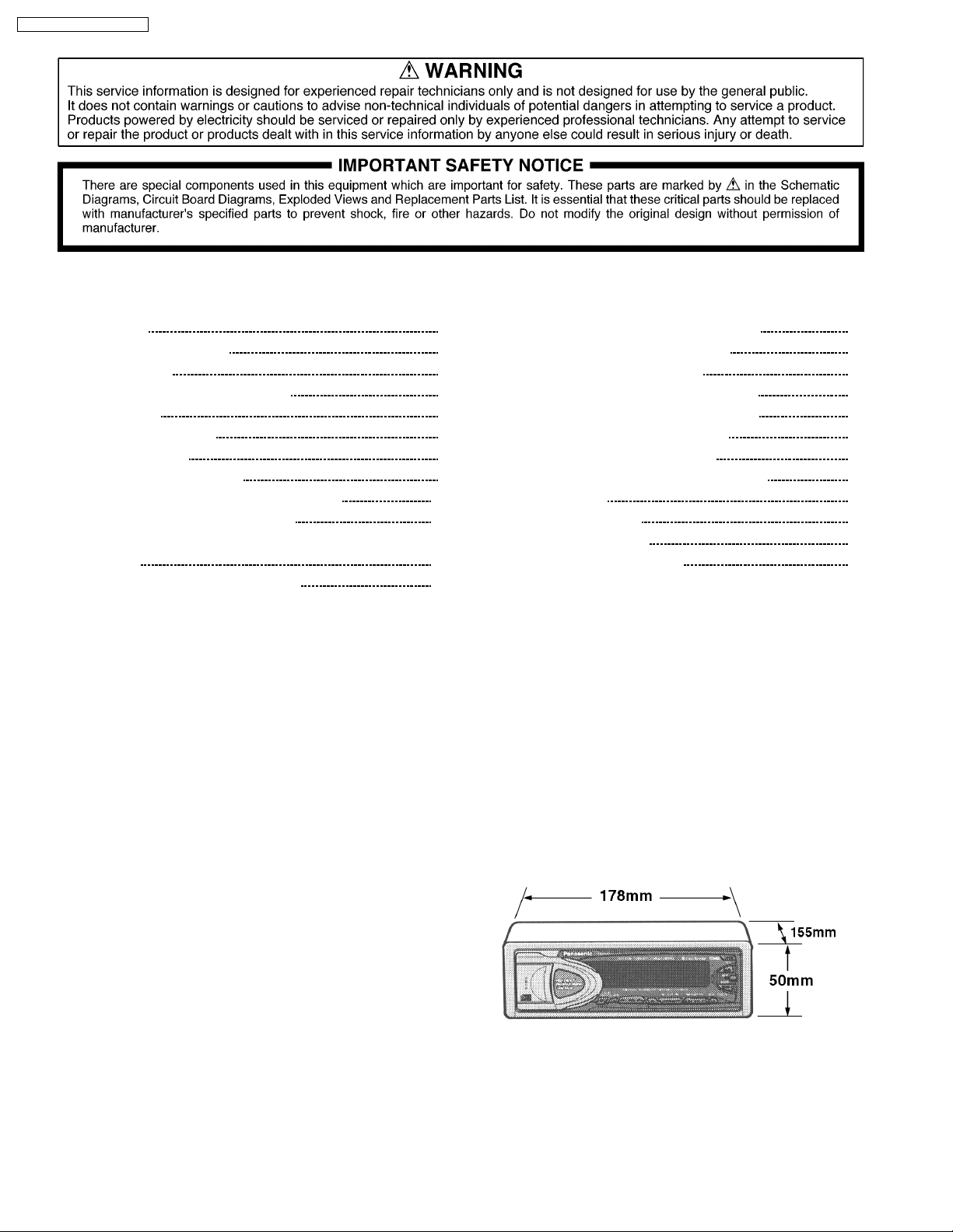
Dimensions** 178(W) ×50(H) ×155(D)(mm)
Weight** 1.9kg
* Specifications and the design are subject to possible modification
without notice due to improvements.
** Dimensions and Weight shown are approximate.
© 2000 Matsushita Communication Industrial Co.,
Ltd. All rights reserved. Unauthorized copying and
distribution is a violation of law.
CQ-DRX900N / CQ-FRX920N
CONTENTS
Page Page
1 FEATURES 2
2 REPLACEING THE FUSE
3 MAINTENANCE
4 RADIO AND CD DECK ALIGNMENT
5 DIMENSIONS
6 WIRING CONNECTION
7 BLOCK DIAGRAM
8 TERMINALS DESCRIPTION
9 ALIGNMENT INSTRUCTIONS [CQ-FRX920N]
10 ALIGNMENT POINTS [CQ-FRX920N]
11 RE-ASSEMB LY PROCEDURE for REEL PWB Assy [CQ-
FRX920N]
12 PACKAGE AND IC BLOCK DIAGRAM
13 REPLACEMENT PARTS LIST [CQ-DRX900N] 21
14 EXPLODED VIEW (Unit) [CQ-DRX900N]
2
2
15 C D PLAYER PARTS[CQ-DRX900N]
2
16 EXPLODED VIEW (CD Deck) [CQ-DRX900N]
17 REPLACEM ENT PARTS LIST [CQ-FRX920N]
2
3
18 EXPLODED VIEW (Unit) [CQ-FRX920N]
19 TAPE PLAYER PARTS[CQ-FRX920N]
5
8
20 EXPLODED VIEW (Tape Deck) [CQ-FRX920N]
12
21 WIRING DIAGRAM
22 SCHMATIC DIAGRAM -1
12
23 SCHEMATIC DIAGRAM -2
13
24 CD Servo Block [CQ-DRX900N]
14
28
29
31
32
39
40
42
43
50
51
57
1 FEATURES
· PLL (Phase Locked Loop) synthesized tuning.
· 18-FM, 6-AM presets with preset scan.
· 5W Center Speaker Power Output.
· DSP Sound Control.
· Intelligent Volume Control.
· Removable face plate.
2 REPLACEING THE FUSE
Use fuses of thesame specified rating 15 amps. Using different
substitutes or fuses with higher ratings, or connecting the unit
directly without a fuse, could cause fire or damage to the stereo
unit.
3 MAINTENANCE
Your products is designed and manufactured to ensure a
minimum of maintenance. Use a soft cloth for routine exterior
cleaning. Never use benzine, thinner or other solvent.
4 RADIO AND CD DECK
ALIGNMENT
! RADIO BLOCK
Do not align the AM and FM package blocks. When the
package block is necessary, it will be supplied already aligned
at the factory.
! CD DECK BLOCK (Only for CQ-DRX900N)
This model has no servo alignment points because
microcomputer controls the servo circuit.
5 DIMENSIONS
2
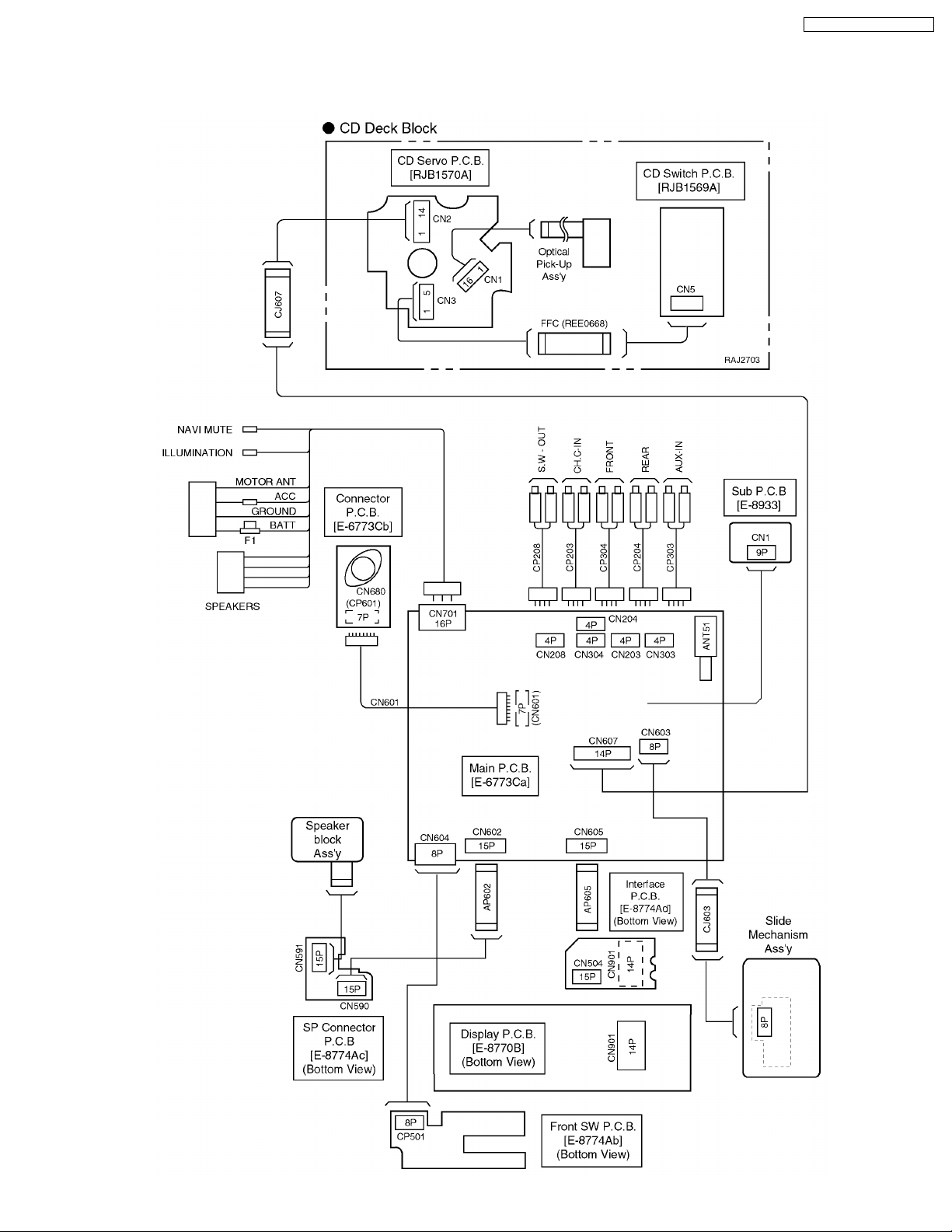
6 WIRING CONNECTION
6.1. CQ-DRX900N
CQ-DRX900N / CQ-FRX920N
3
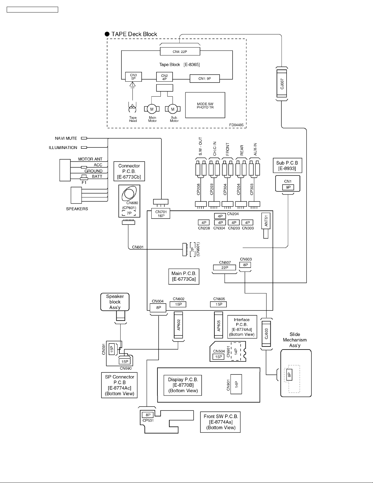
CQ-DRX900N / CQ-FRX920N
6.2. CQ-FRX920N
4
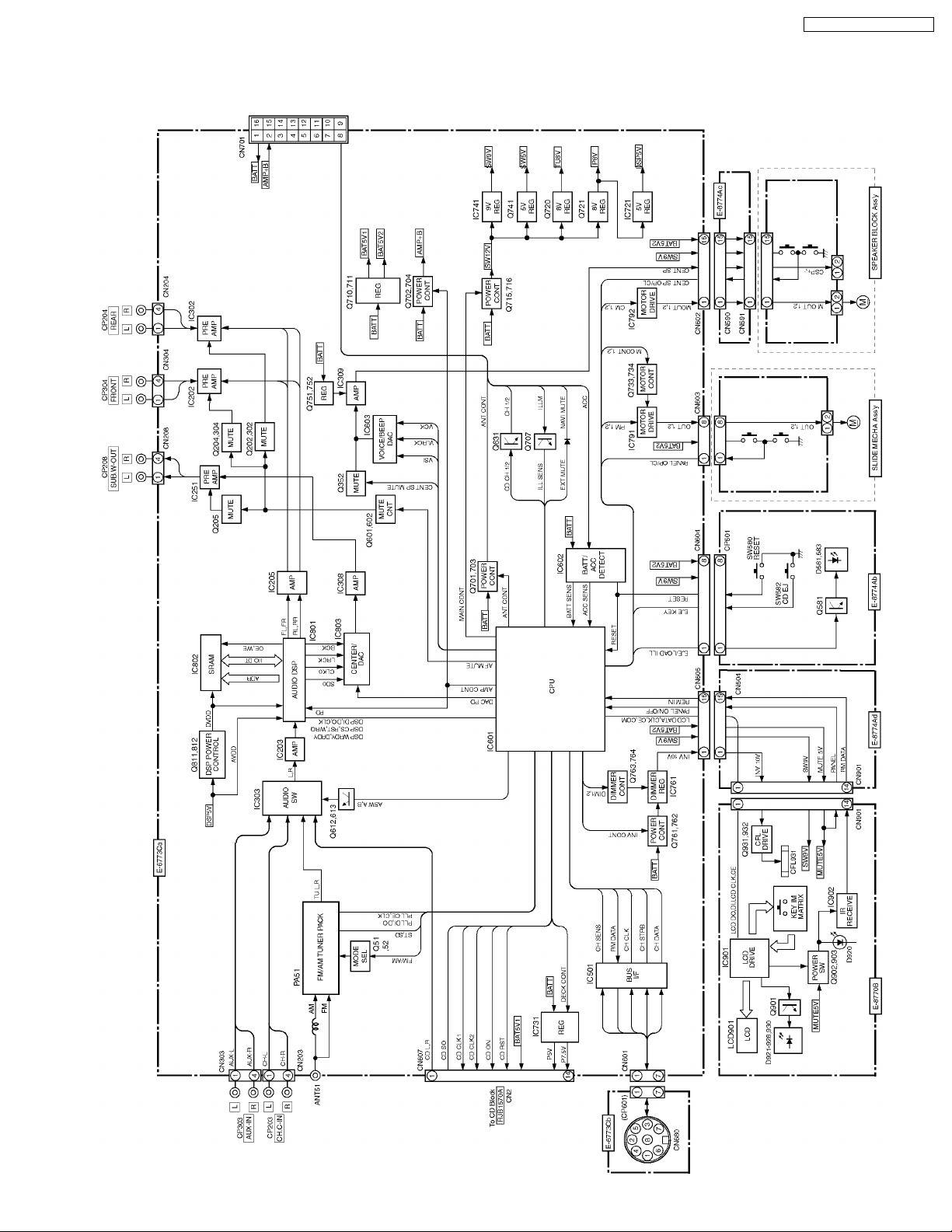
7 BLOCK DIAGRAM
7.1. CQ-DRX900N
CQ-DRX900N / CQ-FRX920N
5
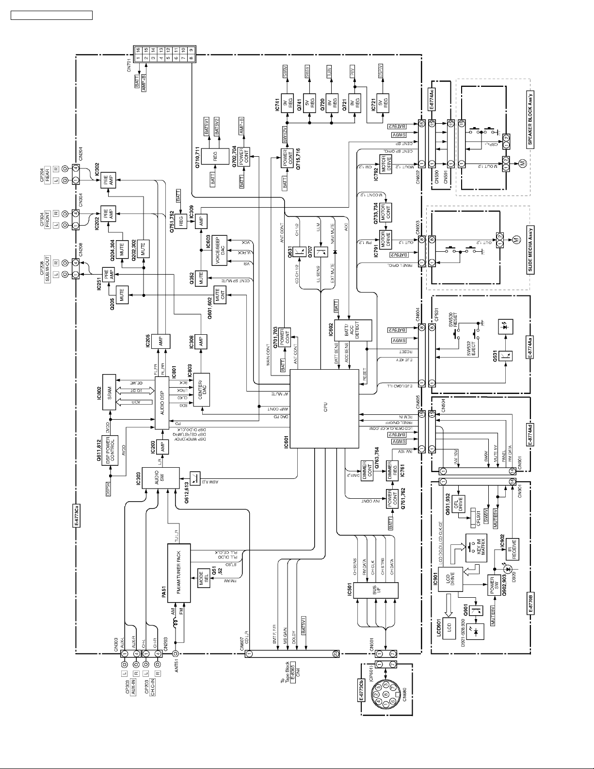
CQ-DRX900N / CQ-FRX920N
7.2. CQ-FRX920N
6
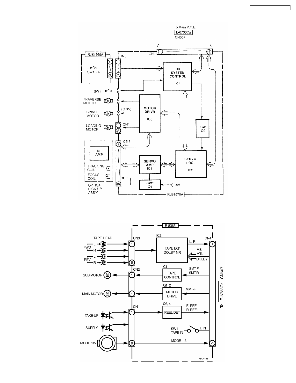
7.3. CD Deck Block [CQ-DRX900N]
CQ-DRX900N / CQ-FRX920N
7.4. Tape Deck Block [CQ-FRX900N]
7
CQ-DRX900N / CQ-FRX920N
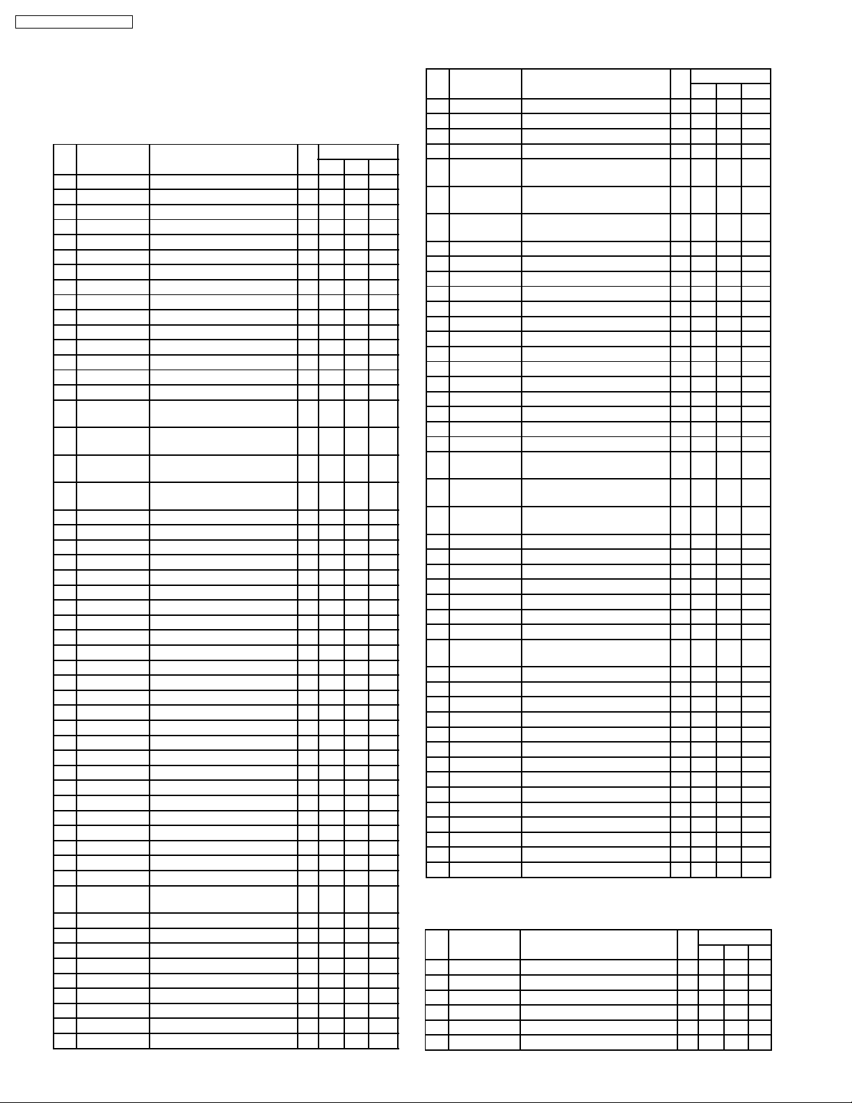
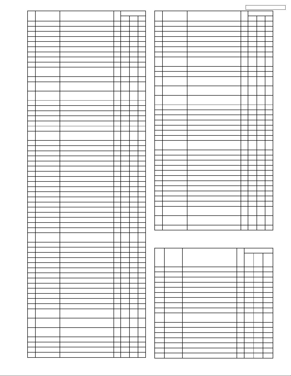
8 TERMINALS DESCRIPTION
8.1. Main Block
IC601 : C2DBKJ000019 (CQ-FRX920N)
Pin
No.
Name Description I/O Vol.(V)
FM AM Tape
1 LCD COM LCD driver serial data O 1.5 1.5 1.5
2 LCD CLK LCD driver serial clock O 4.7 4.7 4.7
3 DSP DATA DSP serial data I 2.1 2.1 2.1
4 DSP COM DSP serial data O 0 0 0
5 DSP CLK DSP serial clock O 5 5 5
6 EVDD +5V power supply - 5.1 5.1 5.1
7 EVSS Ground - 0 0 0
8 LCD CE LCD driver Chip Enable O 0 0 0
9 DSP DRDY DSP data read I 0 0 0
10 REM IN Remote control datq I 3.7 3.7 3.7
11 DSP WRDY DSP Write Enable I 4.9 4.9 4.9
12 PLL DATA PLL IC serial data I 4.7 4.7 4.7
13 PLL COM PLL IC serial data O 0 0 0
14 PLL CLK PLL IC serial clock O 5.1 5.1 5.1
15 CD CH 1/2 Twin Changer 1/2 select O 0 5.1 5.1
16 CENT SP
MUTE
17 VOICE DATA PWM data for Center
18 VPP Hgh Voltage terminal for
19 TUNER
MODE
20 ALARM LED - - - - 21 MAIN CONT Main power control O 5 5 5
22 DSP CS DSP Chip Select O 0 0 0
23 DSP WRQ DSP reset O 4.9 4.9 4.9
24 DAC PD Ext. DAC reset O 5.1 5.1 5.1
25 PRE I/O SEL In/Out select for pre-out O 0 0 0
26 AMP CONT Power amp. select O 5 5.1 5.1
27 ASWA Sourse select A O 5 5.1 0
28 ASWB Sourse select B O 5 5.1 5.1
29 NC - - - - 30 ST FM stereo signal I 4.7 4.7 4.8
31 RESET System reset I 5 0 5
32 SUB XT1 Sub system clock osc. I 0 0 0
33 NC - - - - 34 REGC Regulator filter capacitor - 3.4 3.4 3.4
35 X2 Main system clock osc. I 1.6 1.6 1.6
36 X1 Main system clock osc. - 1.6 1.6 1.6
37 VSS Ground - 0 0 0
38 VDD +5v power supply - 5 5.1 5.1
39 NC - - - - 40 ANT CONT Motor ANT control O 5 5.1 0
41 MS TPS input I 0 0 0
42 MTL Metal tape select O 0 0 0
43 PLL CE PLL IC Chip Enable O 0 0 0
44 DSP RESET DSP reset O 5 5.1 0
45 (NC) Tuner Pack IF selectivity
46 ILL CNT Illumination control for CD O 0 0 0
47 MS GAIN MS gain control O 5.1 5.1 5.1
48 DOLBY B/C Dolby B/C select O 0 0 0
49 F/R Tape FF/REW detection O 5.1 5.1 5.1
50 DOLBY Dolby control O 5.1 5.1 5.1
51 SMT F Servo Motor control O 5.1 5.1 5.1
52 NC - - - - 53 MUTE (NC) - - - 5.1 5.1
54 AF MUTE Audio mute control O 0 5.1 5.1
Center Speaker mute O 0 0 0
O 0 0 5.1
Speaker
- 0 0 0
Programing
FM/AM select O 5 0 0
O 0 0 0
control
Pin
No.
100 LCD DATA LCD driver serial data I 4.2 4.2 4.2
Name Description I/O Vol.(V)
FM AM Tape
55 BVDD +5V power supply - 5.1 5.1 5.1
56 BVSS Ground - 0 0 0
57 VOICE LRCK PWM control clock O 0 0 0
58 VOICE BCLK PWM clock O 5.1 5.1 5.1
59 DIM 2 Dimmer control 1 for display
60 DIM 1 Dimmer control 2 for display
61 INV CONT Power control for display
62 CNT SP H2 Center Speaker close control O 0 0 0
63 CNT SP H1 Center Speaker open control O 0 0 0
64 PANEL H2 Front Panel close control O 5 5 5.1
65 PANEL H1 Front Panel open control O 0 5 0
66 CD RST CD reset O 0 0 0
67 NC - - - - 68 CD SO CD serial data I/O 2.5 2.5 1.2
69 CD CLK1 CD clodk O 5 5 5
70 CD ON CD enable control O 5 5 5
71 AVDD +5V power supply - 5.1 5.1 5.1
72 AVSS Ground - 0 0 0
73 AVREF Reference voltage (for ADC) I 5.1 5.1 5.1
74 SD Signal strength detect I 0 0 0.6
75 INIT A Initialize A I 0 0 2.6
76 CENT SP
OP/CL
77 PANEL
OP/CL
78 PANEL
ON/OFF
79 NC (Resistor pull down) - 0 0 0
80 INIT B Initialize B I 0 2.6 2.6
81 ACC SEN ACC voltage detect I 5 5 5.1
82 NC - - 0 0 0
83 EXT MUTE Mute signal from external I 0 0 5.1
84 ILL SENS Illumination signal I 0 5.1 5.1
85 CH SENS Twin Changer adaptor detect I 4.8 4.8 4.8
86 CH RM DATA Remote control data for
87 CH STRB Changer control strobe signal I 0 0 0
88 CD CLK2 RDS decoder clock I 5 5 5
89 NC (Resistor pull down) - - - 90 BATT SEN Battery voltage detect I 0 5.1 5.1
91 EJE EJECT key signal detect I 5.3 5.3 5.3
92 NC - - - - 93 CD MUTE CD mute O 0 0 0
94 CH DATA Changer control data I 0 0 0
95 NC - - - - 96 CH CLK Changer control clock I 0 0 0
97 NC (Resistor pull down) - - - 98 M DC CONT1 Motor control output 1 O 0 0 0
99 M DC CONT2 Motor control output 2 O 0 0 0
back light
back light
back light
Center speaker open/close
detect
Front panel open/close
detect
Front panel on/off detect I 4.6 4.7 4.7
changer control
O 0 0 0
O 0 0 0
O 5 5 5.1
I 0.8 0.8 0.8
I 0 0 0
O 0 5.1 5.1
IC601 : C2DBKJ000020 (CQ-DRX900N)
Pin
Name Description I/O Vol.(V)
No.
1 LCD COM LCD driver serial data O 1.5 1.5 1.5
2 LCD CLK LCD driver serial clock O 4.7 4.7 4.7
3 DSP DATA DSP serial data I 2.1 2.1 2.1
4 DSP COM DSP serial data O 0 0 0
5 DSP CLK DSP serial clock O 5 5 5
6 EVDD +5V power supply - 5.1 5.1 5.1
FM AM CD
8
Pin
Name Description I/O Vol.(V)
No.
FM AM CD
7 EVSS Ground - 0 0 0
8 LCD CE LCD driver Chip Enable O 0 0 0
9 DSP DRDY DSP data read I 0 0 0
10 REM IN Remote control datq I 3.7 3.7 3.7
11 DSP WRDY DSP Write Enable I 4.9 4.9 4.9
12 PLL DATA PLL IC serial data I 4.7 4.7 4.7
13 PLL COM PLL IC serial data O 0 0 0
14 PLL CLK PLL IC serial clock O 5.1 5.1 5.1
15 CD CH 1/2 Twin Changer 1/2 select O 0 5.1 5.1
16 CENT SP
Center Speaker mute control O 0 0 0
MUTE
17 VOICE DATA PWM data for Center Speaker O 0 0 5.1
18 VPP Hgh Voltage terminal for
- 0 0 0
Programing
19 TUNER
FM/AM select O 5 0 0
MODE
20 ALARM LED - - - - 21 MAIN CONT Main power control O 5 5 5
22 DSP CS DSP Chip Select O 0 0 0
23 DSP WRQ DSP reset O 4.9 4.9 4.9
24 DAC PD Ext. DAC reset O 5.1 5.1 5.1
25 PRE I/O SEL In/Out select for pre-out O 0 0 0
26 AMP CONT Power amp. select
O 5 5.1 5.1
(Internal.External)
27 ASWA Sourse select A O 5 5.1 0
28 ASWB Sourse select B O 5 5.1 5.1
29 NC - - - - 30 ST FM stereo signal I 4.7 4.7 4.8
31 RESET System reset I 5 0 5
32 SUB XT1 Sub system clock osc. I 0 0 0
33 NC - - - - 34 REGC Regulator filter capacitor - 3.4 3.4 3.4
35 X2 Main system clock osc. I 1.6 1.6 1.6
36 X1 Main system clock osc. - 1.6 1.6 1.6
37 VSS Ground - 0 0 0
38 VDD +5v power supply - 5 5.1 5.1
39 NC - - - - 40 ANT CONT Motor ANT control O 5 5.1 0
41 NC - - - - 42 NC - - - - 43 PLL CE PLL IC Chip Enable O 0 0 0
44 DSP RESET DSP reset O 5 5.1 0
45 (NC) Tuner Pack IF selectivity
O 0 0 0
control
46 ILL CNT Illumination control for CD O 0 0 0
47 NC - - - - 48 NC - - - - 49 NC - - - - 50 NC - - - - 51 NC - - - - 52 DECK CONT CD deck power control O 0 5.1 5.1
53 MUTE (NC) - - - 5.1 5.1
54 AF MUTE Audio mute control O 0 5.1 5.1
55 BVDD +5V power supply - 5.1 5.1 5.1
56 BVSS Ground - 0 0 0
57 VOICE LRCK PWM control clock O 0 0 0
58 VOICE BCLK PWM clock O 5.1 5.1 5.1
59 DIM 2 Dimmer control 1 for display
O 0 0 0
back light
60 DIM 1 Dimmer control 2 for display
O 0 0 0
back light
61 INV CONT Power control for display back
O 5 5 5.1
light
62 CNT SP H2 Center Speaker close control O 0 0 0
63 CNT SP H1 Center Speaker open control O 0 0 0
64 PANEL H2 Front Panel close control O 5 5 5.1
65 PANEL H1 Front Panel open control O 0 5 0
CQ-DRX900N / CQ-FRX920N
Pin
Name Description I/O Vol.(V)
No.
FM AM CD
66 CD RST CD reset O 0 0 0
67 NC - - - - 68 CD SO CD serial data I/O 2.5 2.5 1.2
69 CD CLK1 CD clodk O 5 5 5
70 CD ON CD enable control O 5 5 5
71 AVDD +5V power supply - 5.1 5.1 5.1
72 AVSS Ground - 0 0 0
73 AVREF Reference voltage for A/D
I 5.1 5.1 5.1
converter
74 SD Signal strength detect I 0 0 0.6
75 INIT A Initialize A I 0 0 2.6
76 CENT SP
OP/CL
77 PANEL
Center speaker open/close
I 0.8 0.8 0.8
detect
Front panel open/close detect I 0 0 0
OP/CL
78 PANEL
Front panel on/off detect I 4.6 4.7 4.7
ON/OFF
79 NC (Resistor pull down) - 0 0 0
80 INIT B Initialize B I 0 2.6 2.6
81 ACC SEN ACC voltage detect I 5 5 5.1
82 NC - - 0 0 0
83 EXT MUTE Mute signal from external I 0 0 5.1
84 ILL SENS Illumination signal I 0 5.1 5.1
85 CH SENS Twin Changer adaptor detect I 4.8 4.8 4.8
86 CH RM
DATA
Remote control data for
changer control
O 0 5.1 5.1
87 CH STRB Changer control strobe signal I 0 0 0
88 CD CLK2 RDS decoder clock I 5 5 5
89 NC (Resistor pull down) - - - 90 BATT SEN Battery voltage detect I 0 5.1 5.1
91 EJE EJECT key signal detect I 5.3 5.3 5.3
92 NC - - - - 93 CD MUTE CD mute O 0 0 0
94 CH DATA Changer control data I 0 0 0
95 NC - - - - 96 CH CLK Changer control clock I 0 0 0
97 NC (Resistor pull down) - - - 98 MDC
Motor control output 1 O 0 0 0
CONT1
99 MDC
Motor control output 2 O 0 0 0
CONT2
100 LCD DATA LCD driver serial data I 4.2 4.2 4.2
IC801 : YEAMAK7712AF
Pin
Name Description I/O Vol. (V)
No.
1 (NC) - - - - 2 OPCL ADC DAC connecting select I 0 0 0
3 PDAD AD reset control I 0 0 0
4 PDDA DA reset control I 0 0 0
5 PD Power down Input I 5 5 5
6 RST Reset Input I 5 5 5
7 (NC) - - - - 8 (NC) - - - - 9 (NC) - - - - -
10,11DVB Power supply (digital) - 5 5 5
12 (NC) - - - - 13 (NC) - - - - 14 (NC) - - - - 15 (NC) - - - - 16 (NC) - - - - 17 (NC) - - - - 18 (NC) - - - - -
FM AM CD
Tap
e
9
 Loading...