

Page 1
WMA MP3 CD Player/Receiver
English
Model:
CQ-C1505N
Operating Instructions
• Please read these instructions carefully before using this product and keep this manual for future reference.
Page 2
Safety Information
Read the operating instructions for the unit and all other
components of your car audio system carefully before using the
system. They contain instructions about how to use the system in
a safe and effective manner. Panasonic assumes no responsibility
for any problems resulting from failure to observe the instructions
given in this manual.
This pictograph intends to alert you to the presence
of important operating instructions and installation
Warning
instructions. Failure to heed the instructions may result
in severe injury or death.
Warning
Observe the following warnings when using this
unit.
The driver should neither watch the display nor operate
the system while driving.
Watching the display or operating the system will distract the
driver from looking ahead of the vehicle and can cause accidents.
Always stop the vehicle in a safe location and use the parking
brake before watching the display or operating the system.
Use the proper power supply.
This product is designed for operation with a negative grounded
12 V DC battery system. Never operate this product with other
battery systems, especially a 24 V DC battery system.
Protect the Deck Mechanism.
Do not insert any foreign objects into the slot of this unit.
Do not disassemble or modify the unit.
Do not disassemble, modify the unit or attempt to repair the
product yourself. If the product needs to be repaired, consult your
dealer or an authorized Panasonic Service Centre.
Do not use the unit when it is out of order.
If the unit is out of order (no power, no sound) or in an abnormal
state (has foreign objects in it, is exposed to water, is smoking, or
smells), turn it off immediately and consult your dealer.
Refer fuse replacement to qualifi ed service personnel.
When the fuse burns out, eliminate the cause and have it replaced
with the fuse prescribed for this unit by a qualifi ed service
engineer. Incorrect replacement of the fuse may lead to smoke,
fi re, and damage to the product.
This manual uses pictographs to show you how to use the product
safely and to alert you to potential dangers resulting from improper
connections and operations. The meanings of the pictographs
are explained below. It is important that you fully understand the
meanings of the pictographs in order to use this manual and the
system properly.
This pictograph intends to alert you to the presence
of important operating instructions and installation
Caution
instructions. Failure to heed the instructions may result in
injury or material damage.
Observe the following warnings when installing.
Disconnect the lead from the negative (–) battery
terminal before installation.
Wiring and installation with the negative (–) battery terminal
connected may cause electrical shock and injury due to a short
circuit. Some cars equipped with the electrical safety system have
specifi c procedures of battery terminal disconnection.
FAILURE TO FOLLOW THE PROCEDURE MAY LEAD TO THE
UNINTENDED ACTIVATION OF THE ELECTRICAL SAFETY
SYSTEM RESULTING IN DAMAGE TO THE VEHICLE AND
PERSONAL INJURY OR DEATH.
Never use safety-related components for installation,
grounding, and other such functions.
Do not use safety-related vehicle components (fuel tank, brake,
suspension, steering wheel, pedals, airbag, etc.) for wiring or
fi xing the product or its accessories.
Installing the product on the air bag cover or in a
location where it interferes with airbag operation is
prohibited.
Check for piping, gasoline tank, electric wiring, and
other items before installing the product.
If you need to open a hole in the vehicle chassis to attach or wire
the product, fi rst check where the wire harness, gasoline tank,
and electric wiring are located. Then open the hole from outside
if possible.
Never install the product in a location where it interferes
with your fi eld of vision.
Never have the power cord branched to supply other
equipment with power.
After installation and wiring, you should check the
normal operation of other electrical equipment.
The continuation of their using in abnormal conditions may cause
fi re, electrical shock or a traffi c accident.
In the case of installation to an airbag-equipping
car, confi rm warnings and cautions of the vehicle
manufacturer before installation.
Make sure the leads do not interfere with driving or
getting in and out of the vehicle.
Insulate all exposed wires to prevent short circuiting.
Page 3
Caution
Observe the following cautions when using this
unit.
Keep the sound volume at an appropriate level.
Keep the volume level low enough to be aware of road and traffi c
conditions while driving.
This unit is designed for use exclusively in automobiles.
Do not operate the unit for a prolonged period with the
engine turned off.
Operating the audio system for a long period of time with the
engine turned off will drain the battery.
Do not expose the unit to direct sunlight or excessive
heat.
Otherwise these will raise the interior temperature of the unit, and
it may lead to smoke, fi re, or other damage to the unit.
Do not use the product where it is exposed to water,
moisture, or dust.
Exposure of the unit to water, moisture, or dust may lead to
smoke, fi re, or other damage to the unit. Make especially sure that
the unit does not get wet in car washes or on rainy days.
Set the volume level to low enough before the AUX
connection is completed.
Failure to observe this, the loud noise may come out and damage
your speakers and your hearing. Direct connection of the speaker/
headphone output of an external device without any attenuator
may distort sound or damage the connected external device.
Observe the following cautions when installing.
Refer wiring and installation to qualifi ed service
personnel.
Installation of this unit requires special skills and experience. For
maximum safety, have it installed by your dealer. Panasonic is not
liable for any problems resulting from your own installation of the
unit.
Follow the instructions to install and wire the product.
Not following the instructions to properly install and wire the
product could cause an accident or fi re.
Take care not to damage the leads.
When wiring, take care not to damage the leads. Prevent them
from getting caught in the vehicle chassis, screws, and moving
parts such as seat rails. Do not scratch, pull, bend or twist the
leads. Do not run them near heat sources or place heavy objects
on them. If leads must be run over sharp metal edges, protect the
leads by winding them with vinyl tape or similar protection.
Use the designated parts and tools for installation.
Use the supplied or designated parts and appropriate tools to
install the product. The use of parts other than those supplied
or designated may result in internal damage to the unit. Faulty
installation may lead to an accident, a malfunction or fi re.
Do not block the air vent or the cooling plate of the unit.
Blocking these parts will cause the interior of the unit to overheat
and will result in fi re or other damage.
Do not install the product where it is exposed to strong
vibrations or is unstable.
Avoid slanted or strongly curved surfaces for installation. If the
installation is not stable, the unit may fall down while driving and
this can lead to an accident or injury.
Installation Angle
The product should be installed in a horizontal position with the
front end up at a convenient angle, but not more than 30˚.
The user should bear in mind that in some areas there may be
restrictions on how and where this unit must be installed. Consult
your dealer for further details.
Wear gloves for safety. Make sure that wiring is
completed before installation.
To prevent damage to the unit, do not connect the power
connector until the whole wiring is completed.
Do not connect more than one speaker to one set of
speaker leads. (except for connecting to a tweeter)
Information on Disposal for Users of Waste Electrical & Electronic Equipment (private households)
This symbol on the products and/or accompanying documents means that used electrical and electronic products should not be
mixed with general household waste.
For proper treatment, recovery and recycling, please take these products to designated collection points, where they will be
accepted on a free of charge basis. Alternatively, in some countries you may be able to return your products to your local retailer
upon the purchase of an equivalent new product.
Disposing of this product correctly will help to save valuable resources and prevent any potential negative effects on human
health and the environment which could otherwise arise from inappropriate waste handling. Please contact your local authority
for further details of your nearest designated collection point.
Penalties may be applicable for incorrect disposal of this waste, in accordance with national legislation.
For business users in the European Union
If you wish to discard electrical and electronic equipment, please contact your dealer or supplier for further information.
Information on Disposal in other Countries outside the European Union
This symbol is only valid in the European Union.
If you wish to discard this product, please contact your local authorities or dealer and ask for the correct method of disposal.
Page 4
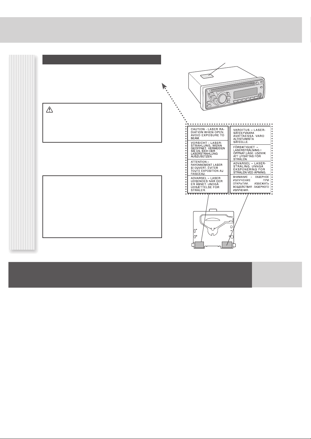
Label Indications and Their Locations
CAUTION
LASER RADIATION WHEN OPEN. DO NOT STARE INTO
BEAM.
Caution:
This product utilizes a laser.
Use of controls or adjustments or performance of
procedures other than those specifi ed herein may
result in hazardous radiation exposure.
CLASS 1 LASER PRODUCT
Caution Label
Laser Product
Do not take apart this unit or attempt to make
any changes yourself.
This unit is a very intricate device that uses a laser
pickup to retrieve information from the surface of
compact discs. The laser is carefully shielded so that its
rays remain inside the cabinet.
Therefore, never try to disassemble the player or alter
any of its parts since you may be exposed to laser rays
and dangerous voltages.
Deck Ass’y (in the unit,
upper side)
Before Reading These Instructions
Panasonic welcomes you to our constantly growing family of electronic products owners.
We endeavor to give you the advantages of precise electronic and mechanical engineering, manufactured with carefully selected components, and
assembled by people who are proud of the reputation their work has built for our company. We know this product will bring you many hours of
enjoyment, and after you discover the quality, value and reliability we have built into it, you too will be proud to be a member of our family.
Page 5
Preparation
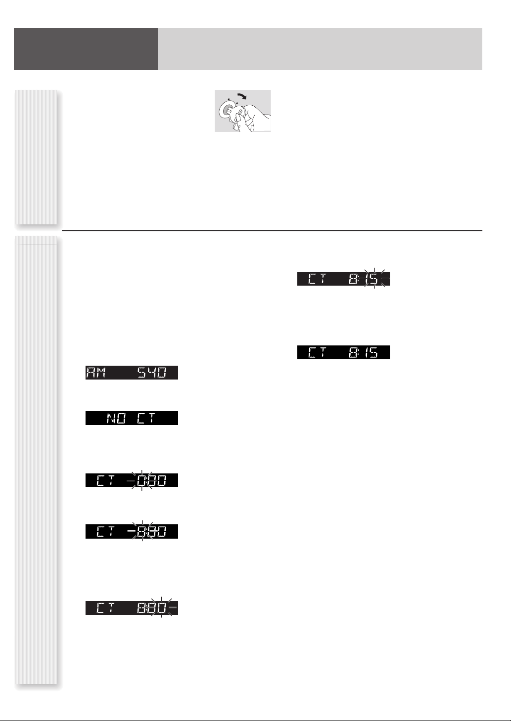
Set your car’s ignition
1
switch to the ACC or ON
position.
Press [SOURCE] (PWR:
2
Power).
First Time Power OnClock Setting
C C A
N O
The 24-hour system is used for the clock.
Notes:
• Adjust the clock when “NO CT” appears on the display.
• When a broadcast of FM Radio Data System is
received, the clock is adjusted automatically by the
Clock Time service.
• Hold down [] or [] to change numbers
rapidly.
Select the radio AM mode. ( “Radio (AM
1
[LW/MW]/FM )”)
Press [DISP].
2
(clock display)
Hold down [DISP] for more than 2
3
seconds.
Hour blinks
Adjust the hour.
4
Hour entered
Adjust the minute.
6
[]: sets the minute ahead.
[]: sets the minute back.
Press [DISP].
7
Minute entered
Completed
[]: sets the hour ahead.
[]: sets the hour back.
Press [DISP].
5
Minute blinks
Page 6
Accessories
Operating Instructions
(English : YEFM285908)
(Deutsch : YEFM285909)
(Français : YEFM285910)
(Nederlands : YEFM285911)
(Svenska : YEFM285912)
(Italiano : YEFM285913)
(Español : YEFM285914)
(Dansk : YEFM285915)
(Polski : YEFM285916)
(Česky : YEFM285917)
(Magyar : YEFM285918)
(Pуccкий : YEFM285919)
Installation Instructions
(English, Deutsch, Français,
Nederlands : YEFM294288)
(Svenska, Italiano, Español,
Dansk : YEFM294289)
(Polski, Česky, Magyar,
Pуccкий : YEFM294290)
PAN EUROPEAN
GUARANTEE
(Warranty Card)
Q’ty: 1 set
Q’ty: 1 set
Q’ty: 1
Installation Kit (YEP0FZ5700)
Q’ty: 1 set
Lock Cancel Plate
Mounting Bolt
Mounting Collar
(YEFX0217263A)
Trim Plate
(YEFC051020)
Power Connector
(YEAJ02874)
Removable Face Plate
Case
(YEFA131839A)
Power
Mode
(Source)
(5 mm )
Q’ty: 1
Q’ty: 1
Q’ty: 1
Q’ty: 1
Notes:
• The number in parentheses underneath
each accessory part name is the part
number for maintenance and service.
• Accessories and their part numbers are
subject to modifi cation without prior notice
due to improvements.
• Mounting Collar and Trim Plate are
mounted on the main unit at shipment.
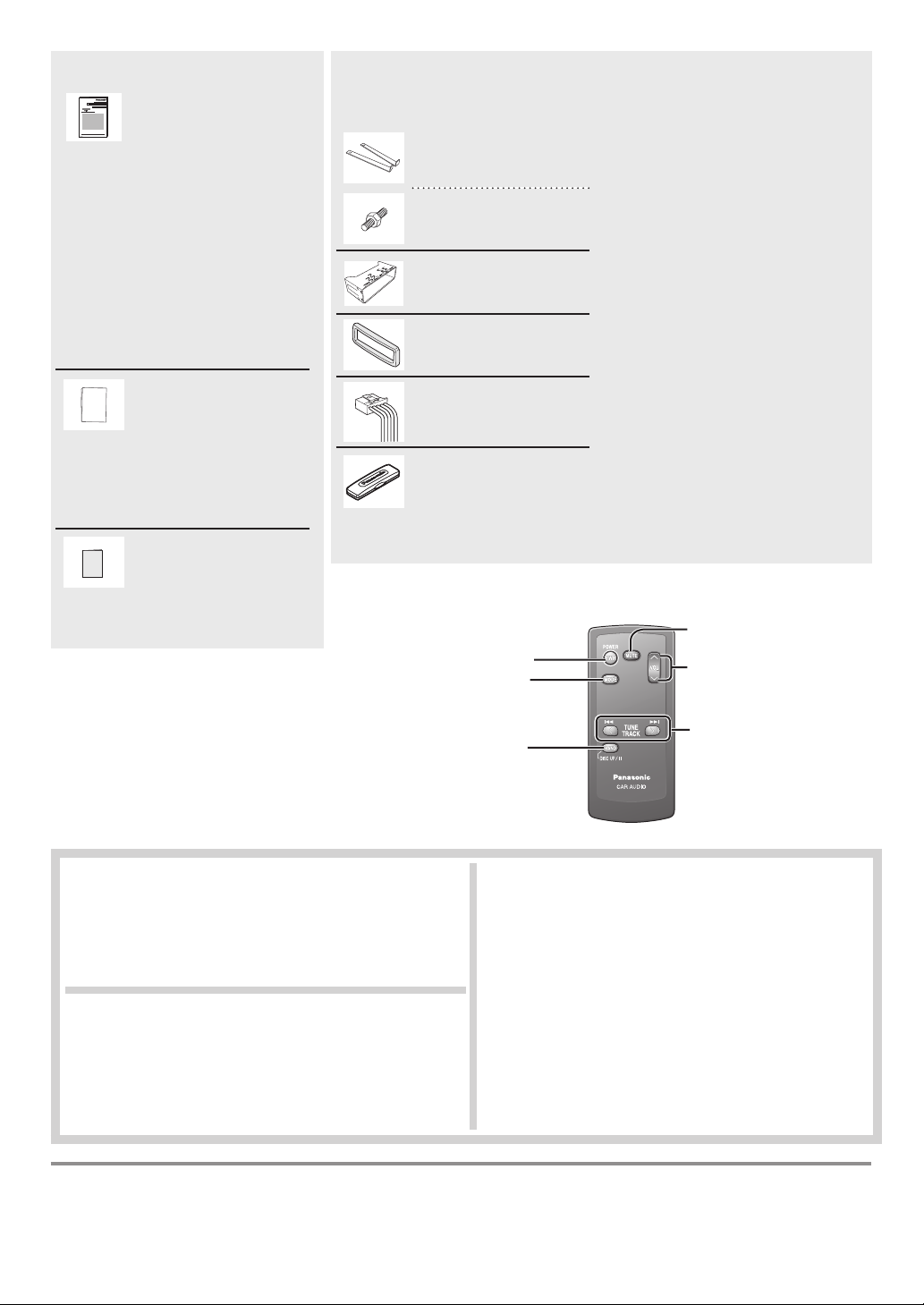
(CA-RC80N)
Mute/attenuation
Volume
Notes:
• Remote Control Unit for CQ-C1505N is option (CA-RC80N).
• The optional remote control is available from your local dealer.
(CA-RC80N)
Sales and Support Information
For UK and Ireland customers only.
Customer Care Centre
• For customers within the UK: 08705 357357
• For customers within the Republic of Ireland: 01 289 8333
• Visit our website for product information
• E-mail: customer.care@panasonic.co.uk
Matsushita Electric Industrial Co., Ltd.
Web Site: http://panasonic.net
Tune
Band
Pause
Track selection
Fast forward/fast reverse
Direct Sales at Panasonic UK
• Order accessories and consumable items for your product
with ease and confi dence by phoning our Customer Care
Centre Monday - Thursday 9:00am - 5:30pm, Friday 9:30am
- 5:30pm. (Excluding public holidays).
• Or go on line through our Internet Accessory ordering
application at www.panasonic.co.uk.
• Most major credit and debit cards accepted.
• All enquiries, transactions and distribution facilities are
provided directly by Panasonic UK Ltd.
• It couldn’t be simpler!
• Also available through our Internet is direct shopping for a
wide range of fi nished products, so take a browse on our
website for further details.
YEFM285908B FT1006-2116 Printed in China
Page 7
Notes on Discs
If you use commercial CDs,
they must have either of these labels shown at right.
Some copy-protected music CDs are not playable.
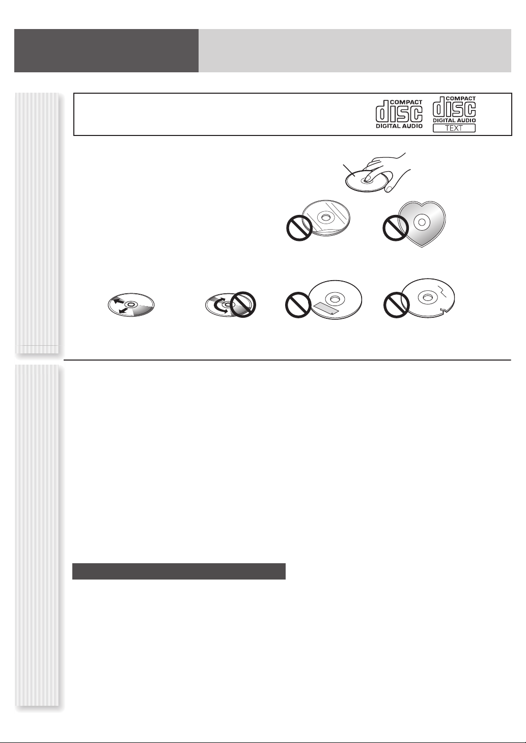
How to hold the disc
• Do not touch the underside of the disc.
• Do not scratch on the disc.
• Do not bend the disc.
• When not in use, keep disc in the case.
Do not leave discs in the following places:
• In direct sunlight
• Near car heaters
• Dirty, dusty and damp areas
• On seats and dashboards
Disc cleaning
Notes on CD/CD Media
Use a dry, soft cloth to wipe from the center outward.
(CD-ROM, CD-R, CD-RW)
<Correct>
Do not write on the disc label with a ballpoint
pen or other hard-point pens.
• You may have trouble playing back some CD-R/RW discs
recorded using CD recorders (CD-R/RW drives), either
due to their recording characteristics or dirt, fi ngerprints,
scratches, etc. on the disc surface.
• CD-R/RW discs are less resistant to high temperatures and
high humidity than ordinary music CDs. Leaving them inside
a car for extended periods may damage and make playback
impossible.
• Some CD-R/RWs cannot be played back successfully due to
incompatibility among writing software, a CD recorder (CDR/RW drive) and the discs.
• This player cannot play the CD-R/RW discs if the session is
not closed.
• This player cannot play the CD-R/RW discs which contain
other than CD-DA or MP3/WMA data (Video CD, etc.).
• Be sure to observe the instructions of the CD-R/RW disc for
handling it.
<Wrong>
Printed side
Labels created by a printer,
Protective fi lms or sheets
Disc with adhered
stickers or tape
• You may encounter trouble in playing MP3/WMA fi les or
displaying the information of MP3/WMA fi les recorded with
certain writing software or CD recorders.
• The fi le extension “.mp3” or “.wma” should be assigned to
each fi le depending on the fi le format.
• This unit does not have the play list function.
• Although Multi-session recording is supported, the use of
Disc-at-Once is recommended.
Irregularly shaped discs
Discs with cracks, scratches
or parts missing
Supported fi le systems
ISO 9660 Level 1/Level 2, Apple Extension to ISO 9660, Joliet,
Romeo
Note: Apple HFS, UDF 1.50, MIX mode CD, CD Extra is not
supported.
Compression formats
(Recommendation: “Points to remember when making
MP3/WMA fi les” on the right.)
Recording MP3/WMA fi les on a CD-media
• You are recommended to minimize the chances of making
Notes on CD-Rs/RWs
a disc that contains both CD-DA fi les and MP3/WMA fi les.
• If CD-DA fi les are on the same disc as MP3 or WMA fi les,
the songs may not play in the intended order, or some
songs may not play at all.
• When storing MP3 data and WMA data on the same disc,
use different folders for each data.
• Do not record fi les other than MP3/WMA fi les and
unnecessary folder on a disc.
• The name of MP3/WMA fi le should be added by rules as
shown in the following descriptions and also comply with
the rules of each fi le system.
• MPEG 1 audio layer 3
Bit rate: 32 k–320 kbps
VBR: Yes
Sampling frequency:
32, 44.1, 48 kHz
• Windows Media Audio Ver. 7, 8, 9*
Bit rate: 32 k–192 kbps
VBR: Yes
Sampling frequency:
32, 44.1, 48 kHz
* WMA 9 Professional/LossLess/Voice are not supported.
• MPEG 2 audio layer 3
Bit rate: 8 k–160 kbps
VBR: Yes
Sampling frequency:
16, 22.05, 24 kHz
Page 8
Notes on MP3/WMA
Note: MP3/WMA encoding and writing software is not supplied with this unit.
Points to remember when making MP3/WMA fi les
Common
• High bit rate and high sampling frequency are recommended
for high quality sounds.
•
Selecting VBR (Variable Bit Rate) is not recommended because
playing time is not displayed properly and sound may be skipped.
• The playback sound quality differs depending on the
encoding circumstances. For details, refer to the user
manual of your own encoding software and writing software.
MP3*
• It is recommended to set the bit rate to “128 kbps or more”
and “fi xed”.
*
MPEG Layer-3 audio coding technology licensed from
Fraunhofer IIS and Thomson.
WMA
•
It is recommended to set the bit rate to “64 kbps or more” and “fi xed”.
• Do not set the copy protect attribute on the WMA fi le to
enable this unit to play back.
Notes:
•
With some software in which MP3/WMA format fi les have been
encoded, the character information may not be displayed properly.
• Undisplayable characters and symbols will be converted
into an asterisk (
).
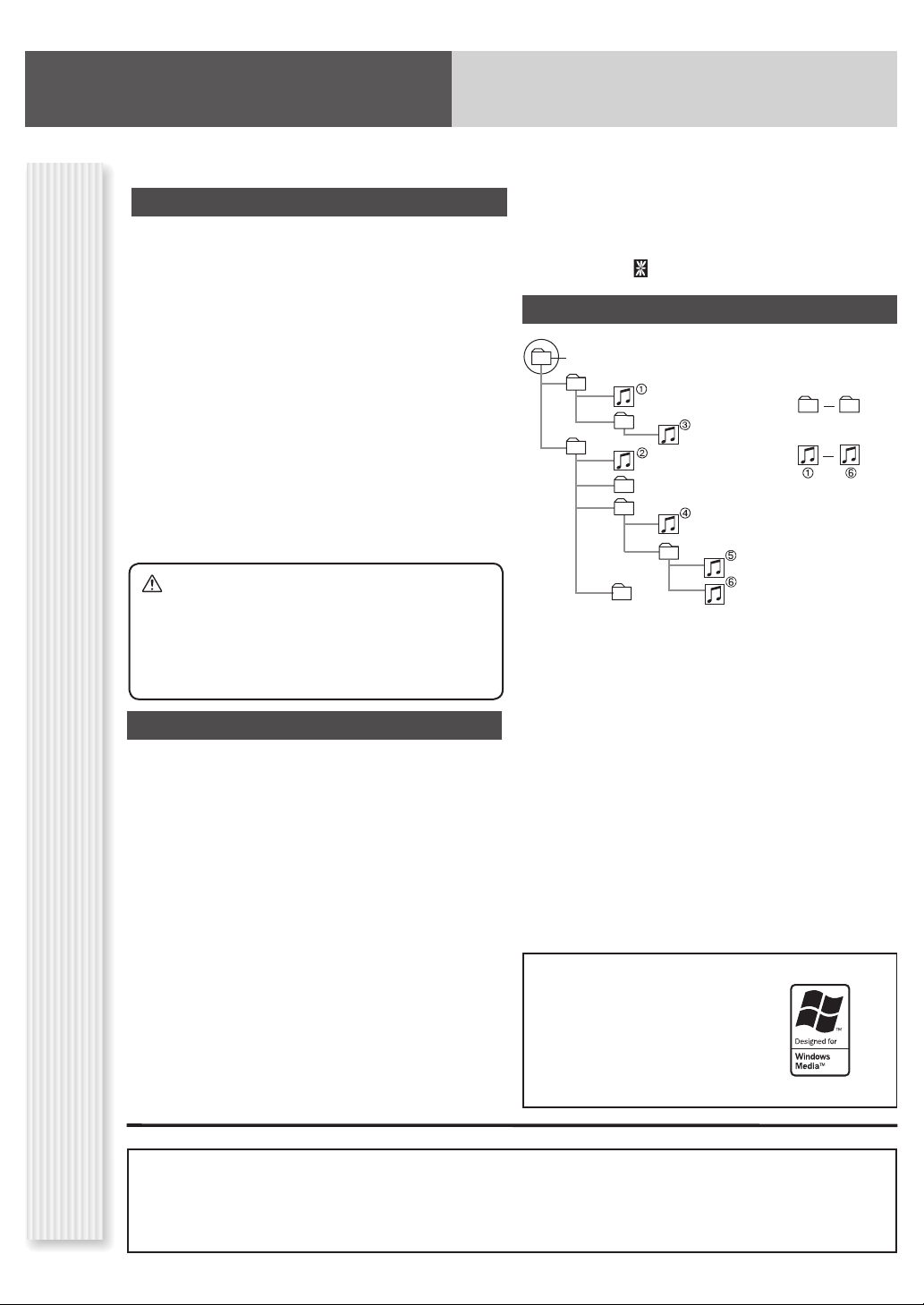
Folder selection order/fi le playback order
Root folder (Root Directory)
1
8
Folder Selection
In the order
File Selection
In the order
1
8
2
4
3
5
6
Caution
• Never assign the “.mp3”, or “.wma” fi le name
extension to a fi le that is not in the MP3/WMA
format. This may not only produce noise from
the speaker damage, but also damage your
hearing.
Display Information
Displayed items
Notes on MP3/WMA
• CD-TEXT
Disc title Album name
Track title Title name/Artist name
• MP3/WMA • WMA (WMA tag)
Folder name Album name
File name Title name/Artist name
Displayable characters
• Displayable length of file name/folder name: within
32 characters. (Unicoded file and folder names are reduced
by half in the number of displayable characters.)
• Name fi les and folders in accordance with the standard of
each fi le system. Refer to the instructions of writing software
for details.
• ASCII character set and special characters in each language
can be displayed.
• MP3 (ID3 tag)
7
Tree 1 Tree 2 Tree 3 Tree 4 ......................... Tree 8
(Max.)
Maximum number of fi les/folders
• Maximum number of fi les: 999
• Maximum number of fi les in one folder: 255
• Maximum depth of trees: 8
• Maximum number of folders: 255 (Root folder is included.)
Notes:
• This unit counts the number of folders irrespective of the
presence or absence of MP3/WMA fi le.
•
If the selected folder does not contain any MP3/WMA fi les, the
nearest MP3/WMA fi les in the order of playback will be played.
• Playback order may be different from other MP3/WMA
players even if the same disc is used.
• “ROOT” appears when displaying the root folder name.
Windows Media, and the
Windows logo are trademarks,
or registered trademarks of
Microsoft Corporation
in the United States
and/or other
countries/regions.
Copyright
It is prohibited by copyright laws to copy, distribute and
deliver copyrighted materials such as music without the
approval of copyright holder except enjoying yourself
personally.
No warranty
Above description complies with our investigations as of
September 2006. It has no warranty for reproducibility and
displayability of MP3/WMA.
Page 9

Maintenance/Fuse
Your product is designed and manufactured to ensure the minimum of maintenance. Use a dry, soft cloth for routine
exterior cleaning. Never use benzine, thinner, or other solvents.
Unit
Cleaning the
If the fuse blows out, consult your dealer, or your nearest authorized Panasonic Service Centre.
Warning
(15 A)
Fuse
Use fuses of the same specifi ed rating
•
without a fuse could cause fi re or damage to the unit. If the replaced fuse fails, contact your nearest authorized Panasonic
Service Centre.
Anti-Theft System
. Using substitutes or fuses with higher ratings, or connecting the unit directly
This unit is equipped with a removable face plate. Removing this face plate makes the unit totally inoperable.
Caution
• This face plate is not waterproof. Do not expose it to water
or excessive moisture.
• Do not remove the face plate while driving your car.
• Do not place the face plate on the dashboard or nearby
areas where the temperature rises high.
Removing
Turn off the power.
1
Press []. The face plate will open.
2
Pull it out toward you.
3
Pull the face plate in the case.
4
(Anti-Theft System)
Face Plate Removing/Mounting
• Do not touch the contacts on the face plate and the main
unit, since this may result in poor electrical contact.
• If dirt or other foreign substances get on the contacts,
wipe them off with a clean and dry cloth.
Mounting
Slide the left side of the face plate in place.
1
Press the right end of face plate until a
2
“click” is heard.
[]
Page 10

Specifi cations
Disc PlayerRadio General
Power supply
Current consumption
Maximum power output
Power output
Tone adjustment range
Speaker impedance
Pre-amp output voltage
Pre-amp output
impedance
Dimensions (W x H x D)
Weight
Front AUX input
Input impedance
Allowable external
input
Connector
Sampling frequency
DA converter
Pick-up type
Light source
Wave length
Frequency response
Signal to noise ratio
Total harmonic distortion
Wow and fl utter
Channel separation
DC 12 V (11 – 16 V), test voltage 14.4 V, negative ground
Less than 2.1 A (CD mode; 0.5 W 4 channels)
50 W x 4 (at 1 kHz), volume control maximum
22 W x 4 (DIN 45 324, at 4 )
Bass: ±12 dB at 100 Hz, Treble: ±12 dB at 10 kHz
4 – 8
2.5 V (CD mode, 1 kHz, 0 dB)
200
178 x 50 x 160 mm
1.3 kg
10 k
2.0 V
3.5 mm Stereo mini-pin
8 times oversampling
1 bit DAC System
Astigma 3-beam
Semiconductor laser
790 nm
20 Hz – 20 kHz (±1 dB)
96 dB
0.01 % (1 kHz)
Below measurable limits
75 dB
FM
Frequency Range
Usable Sensitivity
Stereo Separation
AM (MW)
Frequency Range
Usable Sensitivity
AM (LW)
Frequency Range
Usable Sensitivity
Notes:
• Specifi cations and design are subject to modifi cation without notice due to improvements.
• Some fi gures and illustrations in this manual may be different from your product.
87.5 MHz – 108 MHz
6 dB/µV (S/N 30 dB)
35 dB (at 1 kHz)
531 kHz – 1 602 kHz
28 dB/µV (S/N 20 dB)
153 kHz – 279 kHz
32 dB/µV (S/N 20 dB)
Page 11

General
selects a source.
(PWR) (Power)
toggles power on/off.
[VOL] (Volume)[SOURCE] (Source)
[TA/AF]
“Radio Data
(
System (RDS) in FM
Broadcasting”)
[MUTE]
toggles mute on/off.
(SQ) (Sound Quality)
selects a sound type (SQ). (Hold it down for more
than 1 second.)
Remote Control Sensor
Power On/Off
Set your car’s ignition switch to the ACC or ON position.
Power on: Press [SOURCE] (PWR).
Power off: Hold down [SOURCE] (PWR) for
more than 1 second.
Source Selection
Press [SOURCE] to change the source.
Radio Disc Player AUX IN
Volume Adjustment
(Setting Range: 0 to 40, Default: 18)
Turn [VOL].
Mute
General Operations
ON: Press [MUTE]. ( lights.)
OFF: Press [MUTE] again.
Caution
• Set the volume level to
low enough before the AUX
connection is completed.
Failure to observe this, the loud
noise may come out and damage
your speakers and your hearing.
SQ (Sound Quality)
SQ is a function that can call up various sound types at the
touch of button in accordance with your listening music
type.
Hold down [MUTE] (SQ) (Sound Quality) for
1 sec. or more to select the sound type (SQ)
as follows:
*
Notes:
• If no operation takes place for more than 5 seconds in
SQ selection mode, the display returns to the regular mode.
•
Settings of SQ, bass and treble are infl uenced one another.
If such an infl uence causes distortion to the audio
readjust bass/treble or volume.
• For further information on Bass, Treble, Balance and Fader
settings, refer to Audio Settings.
*[AUX] (AUX IN)
From line output of external sound/audio
device (ex. Silicon-audio player, HDD player,
etc.)
*AUX IN:
(3.5 mm stereo)
(FLAT) fl at frequency
response:
does not emphasize any part.
(Default)
(ROCK) speedy and heavy
sound:
exaggerates bass and treble.
(POP) wide-ranged and deep
sound:
slightly emphasizes bass and
treble.
(VOCAL) clear sound:
emphasizes middle tone and
slightly emphasizes treble.
the
signal,
Page 12

Radio (AM [LW/MW]/FM)
[SOURCE] (Source)
selects a source.
[DISP] (Display)
switches the information on the display.
[BAND]
selects a band in the radio source.
(APM) (Auto Preset Memory)
executes APM in the radio source. (Hold it down for more than 2 seconds.)
[TUNE ] [TUNE ]
down/up the frequency. (Hold it
down for more than 0.5 seconds
and release it for seek tuning.)
[1] to [6]
selects a preset station in the radio source,
and presets the current station. (Hold it down for more
than 2 seconds.)
Press [SOURCE] to select the radio source.
1
Press [BAND] to select a band.
2
Select a station.
3
Operation Flow
Frequency adjustment
[TUNE ]: Lower
[TUNE ]: Higher
Note: Hold down for 0.5 sec. or more and release for station
search.
Preset station selection
Press the corresponding preset button from [1] to [6] to tune
into a preset station.
Page 13

Band Frequency Preset Number
lights while receiving an FM stereo signal.
Display change
Press [DISP] to change the display.
AM (LW/MW) mode:
Band/frequency
CT (Clock Time)
FM (not RDS) mode:
Band/frequency
PS
CT
Radio Source DisplayStation Preset
Up to 6 stations can be preset in AM (LW/MW), FM1, FM2, and
Preset stations can be simply called up by pressing one of the preset buttons from [1] to [6].
Auto Preset Memory (APM)
With this operation, stations with good receiving conditions
can be automatically stored in the preset memory.
Select a band.
1
Hold down [BAND] (APM) for more than
2
2 seconds.
The preset stations under best receiving conditions are
received for 5 seconds each after presetting the stations
(SCAN). To stop scanning, press one of the buttons from
[1] to [6].
Note: New stations overwrite existing saved stations.
RDS mode:
PS (Programme Service name)
Band/frequency
CT
FM3 respectively.
Manual station preset
Tune into a station.
1
Hold down one of the preset buttons from
2
[1] to [6] for more than 2 seconds.
(blinks once)
Note: New stations overwrite existing saved stations.
Page 14

Player (Disc Player)
Disc slot
takes a disc in with the printed side facing
up.
Note: A disc which has both CD-DA data
and MP3/WMA data on it may not be
reproduced normally.
[SOURCE] (Source)
selects a source.
() (Play/Pause)
toggles pause/play in the
player source.
[] (Eject)
ejects the disc.
[DISP] (Display)
switches the information
on the display.
[] []
skip to the previous/next track/fi le
in the player mode.
Hold down either of them for fast
reverse/fast forward.
Caution
• Do not insert a disc when the indicator lights.
• Refer to the section of “Notes on Discs” and “Notes on
MP3/WMA”.
• This unit does not support 8 cm discs.
Press [SOURCE] to select the Disc Player
1
source.
Select a desired portion.
2
Track/fi le selection
Press [] / [].
Note: To perform fast forward/reverse, hold down either of
them.
[] []
skip to the previous/next
folder.
• If you insert an 8 cm disc and cannot eject it, turn ACC of your car
off once and turn it on again, then press [] (Eject).
• Do not insert foreign matter into the disc slot.
[4] (RANDOM)/[5] (SCAN)/[6] (REPEAT)
toggles on/off each play mode.
[3] (SCROLL)
scrolls the information on display.
Pause
Press [BAND] ().
Press again to cancel.
Disc Player (CD-DA disc):
Operation Flow
Previous/next track
Disc Player (MP3/WMA disc):
Previous/next fi le
Folder selection (MP3/WMA)
Press [] / [].
Page 15

CD-DA mode display
Track number Play time
Display change
Press [DISP] to change the display.
Disc Player (CD-DA disc): Disc Player (MP3/WMA disc):
Normal
Normal
Lights when the
disc is loaded.
MP3/WMA mode display
Folder number
lights when folder random/
repeat/scan is on.
Player Source DisplayRandom, Repeat, Scan
File number
Play Mode
indicators
Play Mode
indicators
Disc title
Track title
Clock
Play time
Folder name/
Album*
File name/
Title, artist*
Clock
*ID3/WMA Tag On/Off
Hold down [3] for more than
2 seconds.
album title and song title/
artist name are displayed.
(Default)
folder name/fi le name are
displayed.
Notes:
• For scrolling text, press [3] (SCROLL).
• “NO TEXT” is displayed when there is no information on the disc.
Random play
All the available songs (tracks/fi les) are played in a random
sequence.
Press [4] (RANDOM).
Press again to cancel.
Folder random play (MP3/WMA)
All the available fi les in current folder are played in a random
sequence.
Hold down [4] (RANDOM) for more than
2 seconds.
Hold down again to cancel.
Repeat play
The current song (track/fi le) is repeated.
Press [6] (REPEAT).
Press again to cancel.
Folder repeat play (MP3/WMA)
The current folder is repeated.
Hold down [6] (REPEAT) for more than
2 seconds.
Hold down again to cancel.
Scan play
The fi rst 10 seconds of each songs (tracks/fi les) is played in
sequence.
Press [5] (SCAN).
Press again to cancel.
Folder scan play (MP3/WMA)
From the next folder, the fi rst 10 seconds of the fi rst fi le on
each folder is played in sequence.
Hold down [5] (SCAN) for more than
2 seconds.
Hold down again to cancel.
Page 16

Troubleshooting
If You Suspect Something Wrong
Check and take steps as described below.
If the described suggestions do not solve the problem, it is
recommended to take the unit to your nearest authorized Panasonic
Service Centre. The product should be serviced only by qualifi ed
personnel. Please refer the checking and the repair to professionals.
Panasonic shall not be liable for any accidents arising out of neglect
of checking the unit or your own repair after your checking.
Never take measures especially those other than indicated by
italic letters in “Possible Solution” described below because
those are too dangerous for users to handle themselves.
Trouble Possible Solution
Common
• Start the engine. (Or turn the ignition
switch to the ACC position.)
• Verify the wiring. (battery lead, power
No power
No sound
Noise
No sound from
left, right, front,
lead, ground lead, etc.)
• Fuse blown (Contact the nearest
Panasonic Service Centre.)
• Ask a professional for fuse replacement.
• Be sure to use the same rated fuse.
• Disable the mute function.
• Verify the wiring.
• Wait until the dew disappears before
turning on the unit.
• Make sure that grounding is established
properly.
• Adjust the balance and fader.
• Verify the wiring.
or rear speaker
Left and right
• Connect the speaker lead correctly.
sounds are
reversed
Disc Player
No sound,
or disc is
automatically
ejected
Sound skip,
poor sound
quality
Sound skip due
to vibration
Disc not
ejectable
• Load the disc correctly.
• Clean the disc.
• Clean the disc.
• The maximum permissible tilt angle is
30°.
• Secure the unit.
• Press []. If the disc is still not ejected,
contact the nearest Panasonic Service
Centre.
Warning
• Do not use the unit in an irregular condition, for example,
without sound, or with smoke or a foul smell, which can cause
ignition or electric shock. Immediately stop using the unit and
consult your dealer.
• Never try to repair the unit by yourself because it is dangerous
to do so.
Trouble Possible Solution
Radio
• Tune in to another station of high-
Frequent noise
Preset data
deleted
intensity waves.
• Make sure that the antenna mounted
point is grounded properly.
• The preset memory is cleared to return
to the original factory setting when
the power connector or battery is
disconnected.
Error Display Messages
(The disc is ejected automatically.)
The disc is dirty or upside down.
• Check the disc.
(The disc is ejected automatically.)
The disc has scratches.
• Check the disc.
No operation by some cause.
• If normal operation is not restored,
consult your dealer or the nearest
Service Centre to ask for repairs.
Cannot read the fi le
• Check the disc.
A WMA fi le can be copyrighted.
• The fi le protected by copyright is not
playable.
Page 17

Radio Data System (RDS) in FM Broadcasting
Useful functions such asAF, TA, PTY are available in the RDS (Radio Data System)-ready areas.
Some FM stations are broadcasting added data compatible with RDS. This radio set offers convenient functions using such data.
RDS service availability varies with areas. Please understand if RDS service is not available in your area, the following service is
not available, either.
The following functions are available when receiving RDS stations.
AF (Alternative Frequency)
The following functions are available when the AF mode is
active (
• When receiving conditions become bad, a station with better
• When executing APM, only RDS stations are selected.
• When calling up a preset station, a best receiving station is
Notes:
• The AF sensitivity can be adjusted.
• The AF available range can be adjusted. ( “Function
lights).
receiving conditions is automatically tuned in to.
selected automatically. (BSR Best Stations Research)
Settings”)
TA (Traffi c Announcement)
The following functions are available when the TA mode is
active (
What is RDS?AF (Alternative Frequency)
• A TP station is automatically searched for and received at
• When executing station search or APM, only TP stations are
• Setting to TA on with the unit in another mode, it will
lights).
the instant of toggling the TA mode on if you are receiving a
non-TP station or TP station with poor reception.
selected.
automatically switch to radio mode and output the traffi c
announcement when the traffi c announcement begins. The
traffi c announcement having fi nished, the unit will return to
the previous mode. (TA Standby Mode)
PTY (Programme Type)
The following functions are available when the PTY mode is
active.
• The PTY of receiving station appears.
• Programs can be searched for by PTY.
Note: PTY language can be selected. (
“Function Settings”)
Other functions of RDS
CT (Clock Time)
The clock is automatically adjusted.
PS (Programme Service Name)
As well as the frequency, the name of the broadcast station
appears.
EON (Enhanced Other Network)
RDS information is updated constantly in response to the
current position.
EON-TA
Traffi c information from the current and other network stations
can be received.
Emergency Announcement Reception
Emergency announcement automatically appears on the
display when it is received.
AF Level
Hold down [TA] (AF) for more than 2 seconds to select AF
level.
Low level AF operating sensitivity. (Default)
High level AF operating sensitivity.
When the AF network of an RDS station is not
required.
PI Seek (Programme Identifi cation Seek)
If reception becomes poor when tuning in a preset station,
press the same preset number button. The same station with
better reception will be searched for.
Press same preset number button again to cancel.
(blinks)
Note: For PI Seek, cancel the TA mode fi rst, then execute PI
Seek.
Page 18

TA On/Off
Pressing [TA] toggles TA on and off.
Notes:
• This operation is not adjustable by the remote control.
• Traffi c information is available in monaural.
• Adjust the TA volume only while receiving a TA.
Announcement)
Traffi c Information Only (TA Mute)
For listening to only traffi c information, activate TA and set the
volume to 0 in FM mode.
Once traffi c information starts, the volume changes to the TA
volume.
PTY (Programme Type) TA (Traffi c
PTY On/Off
Holding down [DISP] (PTY) for more than 2 seconds toggles
PTY mode on and off.
Programme Search by PTY
Programs can be searched for by use of PTY that has been
originally preset.
Press [1] to [6] to select PTY in the PTY mode.
Programme Type Contents
1 NEWS NEWS
2 SPEECH AFFAIRS, INFO, EDUCATE, DRAMA,
CULTURE, SCIENCE, VARIED,
WEATHER, FINANCE, CHILDREN,
SOCIAL, RELIGION, PHONE IN,
TRAVEL, LEISURE, DOCUMENT
3 SPORT SPORT
4 POP M POP M
5 CLASSICS CLASSICS
6 MUSIC ROCK M, EASY M, LIGHT M,
OTHER M, JAZZ, COUNTRY,
NATION M, OLDIES, FOLK M
Another station in the same PTY is searched for by pressing
[BAND].
Notes:
• When there is no corresponding programme type station,
“NONE” is displayed.
• A desired PTY appears for 5 seconds.
• Preset contents are changeable.
Detailed PTY Selection
Press [] or [] to select PTY.
1
SPEECH MUSIC NEWS AFFAIRS
INFO SPORT EDUCATE DRAMA
CULTURE SCIENCE VARIED POP M
ROCK M EASY M LIGHT M CLASSICS
OTHER M WEATHER FINANCE CHILDREN
SOCIAL RELIGION PHONE IN TRAVEL
LEISURE JAZZ COUNTRY NATION M
OLDIES FOLK M DOCUMENT
Press [BAND].
2
Search starts.
Notes:
• To stop searching, press [BAND] (SET).
• When there is no corresponding programme type station,
“NONE” is displayed.
PTY Preset Change
Original PTY presets can be changed as you like.
Select a PTY that you would like to preset.
1
Follow the procedure of ordinary presetting.
2
( “Station Preset” in “Radio (AM [LW/MW]/
FM)”)
Page 19

Audio Settings
[VOL] (Volume)
selects a value in the audio menu.
(PUSH SEL) (Push to select)
selects items in the audio menu.
[DISP] (Display)
exits from the audio menu.
Press [VOL] (PUSH SEL) to display the audio menu display.
1
Note: If no operation takes place for more than 7 seconds in the audio menu (2 seconds in Main volume adjustment), the
display returns to the regular mode.
Press [VOL] (PUSH SEL) to select a mode
2
to be adjusted.
(Setting Range: 0 to 40, Default: 18)
(Setting Range: –12 dB to +12 dB by 2 dB,
Default: 0 dB)
(Setting Range: –12 dB to +12 dB by 2 dB,
Default: 0 dB)
Audio menu
(Setting Range: 15 levels each, Default CNT (centre))
(Setting Range: 15 levels each, Default CNT (centre))
Volume
Bass
Treble
Balance
Fader
Tur n [VOL] clockwise or counterclockwise
3
to adjust.
: Up
: Down
: Increased
: Decreased
: Increased
: Decreased
: Right enhanced
: Left enhanced
: Front enhanced
: Rear enhanced
Notes:
• If the fader is set to front, the pre-amp. output (rear) is decreased.
For further information on SQ (Sound Quality) settings, refer to General.
•
•
Settings of SQ, bass and treble are infl uenced one another. If such an infl uence causes distortion to the audio
bass/treble or volume.
signal, readjust
Page 20

Function Settings
[VOL]
selects a value in the function menu.
(PUSH SEL) (Push to select)
selects items in the function menu.
[DISP] (Display)
exits from the function menu.
Hold down [VOL] (PUSH SEL) for more than 2 seconds to display the function menu display.
1
Note: If no operation takes place for more than 7 seconds in the function menu, the display returns to the regular mode.
Press [VOL] (PUSH SEL) to select a
2
mode to be adjusted.
Noise is signifi cantly decreased when weak signals are received
from an FM broadcast station.
(Default: OFF)
Only stations with good reception are detected in seek tuning.
(Default: OFF)
Only stations with good reception are detected in seek tuning.
(Default: OFF)
(Default: OFF)
Note: When the Region mode is switched from OFF to ON or
Function Menu
vice versa, the AF mode turns on automatically.
(Default: ENGLISH)
FM Monaural [FM]
FM Local [FM]
AM Local [AM]
Region RDS
PTY Language RDS
Tur n [VOL] clockwise or counterclockwise
3
to adjust.
MONO OFF
MONO ON
lights.)
(
LOCAL OFF
LOCAL ON
lights.)
(
LOCAL OFF
LOCAL ON
lights.)
(
The frequency is
changed also for
programs outside the
region.
The frequency is
changed only for
programs within the
region.
English
Swedish
Change in Luminescent
Color of Buttons
You can select luminescent color of buttons.
(Default: Green)
AUX Skip
If AUX is not used, the AUX mode is skipped
when selecting the source.
(Default: ON (Skip disabled))
Green
Red
Skip disabled.
Skip enabled.
Page 21

Before Wiring/Vor der Verdrahtung/
Avant le câblage/Voor het aansluiten van de bedrading
Exclusively operated with 12 V battery with negative (–)
ground.
Connect the power lead (red) very last.
(for non-ISO connector)
Connect the battery lead (yellow) to the positive (+) terminal
of the battery or fuse block terminal (BAT). (for non-ISO
connector)
Strip about 5 mm of the lead ends for connection.
(for non-ISO connector)
Apply insulating tape to bare leads.
Secure loosened leads.
Dieses Gerät ist ausschließlich für den Anschluss an Bordnetze
mit 12 V Batterie und negativer (–) Klemme an Masse bestimmt.
Schließen Sie den Versorgungsleiter (rot) zum Schluss an.
(wenn kein ISO-Stecker verwendet wird)
Schließen Sie das Batteriekabel (gelb) an die positive (+)
Klemme der Batterie oder an die (BAT) Klemme des
Sicherungsblocks an. (wenn kein ISO-Stecker verwendet wird)
Entfernen Sie etwa 5 mm der Isolierung von den Kabelenden
für den Anschluss. (wenn kein ISO-Stecker verwendet wird)
Isolieren Sie alle freiliegenden Leiter.
Sichern Sie alle losen Leiter.
Alimentez l’appareil absolument par la batterie de 12 V avec
sa polarité négative (–) mise à la masse.
Raccorder le fi l d’alimentation (rouge) en dernier.
(pour un connecteur non-ISO)
Connectez le fi l (jaune) à la borne positive (+) de la batterie
ou à la borne (BAT) de la boîte à fusibles. (pour un connecteur
non-ISO)
Dénudez les extrémités de fi l de 5 mm environ pour la
connexion. (pour un connecteur non-ISO)
Recouvrez les fi ls nus d’un ruban isolant.
Resserrez les connexions de fi ls.
Uitsluitend voor gebruik met een 12 V accusysteem met
negatieve (–) aarding.
Sluit de stroomdraad (rood) pas het allerlaatst aan.
(voor een niet-ISO aansluiting)
Sluit de accudraad (geel) aan op de positieve (+) aansluiting
van de accu of van het zekeringenblok (BAT). (voor een niet-ISO
aansluiting)
Strip ongeveer 5 mm van de uiteinden
van de draden om de verbinding tot
stand te kunnen brengen. (voor een niet-
ISO aansluiting)
Isoleer blote draadeinden met isolatieband.
Zet loshangende draden vast.
EnglishDeutschFrançaisNederlands
WMA MP3 CD Player/Receiver
WMA MP3 CD-Player/Receiver
Récepteur/lecteur CD avec lecture WMA/MP3
WMA MP3 CD-speler/radio
Model: CQ-C1505N
• Please read these instructions carefully before using this product and keep this manual for future reference.
• Bitte lesen Sie diese Bedienungsanleitung vor der Verwendung dieses Produktes aufmerksam durch und bewahren
Sie sie danach für spätere Nachschlagzwecke sorgfältig auf.
• Prière de lire ces instructions attentivement avant d’utiliser le produit et garder ce manuel pour l’utilisation ultérieure.
• Leest u deze instructie alstublieft zorgvuldig door voor u dit product in gebruik neemt en bewaar deze handleiding voor later gebruik.
• Mounting angle side to side
front to rear
: horizontal
: 0 – 30°
• Montagewinkel seitlich
vorne-hinten
: horizontal
: 0 – 30°
• Angle de montage latéral
longitudinal
: horizontal
: 0 – 30°
• Bevestigingshoek links/rechts
voor/achter
: horizontaal
: 0 – 30°
• Mounting space
• Einbauöffnung
• Espace nécessaire pour le montage
• Benodigde ruimte
Supplied Hardware/Mitgeliefertes zubehör/Matériel d’installation/Meegeleverde onderdelen
No. Item Diagram Q’ty No. Item Diagram Q’ty
Mounting Collar
Einbauhalterung
Cadre de montage
Bevestigingskraag
YEFX0217263A
1
Lock Cancel Plate
Verriegelungsfreigabeplatte
Plaque antiblocage
Ontgrendelingsplaat
2
Power Connector
Versorgungsstecker
Connecteur d’alimentation
Stroomstekker
YEAJ02874
1
Mounting Bolt (5 mm )
Befestigungsschraube (5 mm )
Boulon de fi xation (5 mm )
Bevestigingsbout (5 mm )
1
Trim Plate
Abdeckplatte
Plaque de garniture
Afwerkingsrand
YEFC051020
1
and consist of a set. (YEP0FZ5700) und bestehen als Satz. (YEP0FZ5700)
et constituent un jeu. (YEP0FZ5700) en bestaan uit een set. (YEP0FZ5700)
Before Installation/Vor dem Einbau/
Avant l’installation/Voor de installatie
Consult a professional for installation.
• Verify the radio using the antenna and speakers before installation.
Wenden Sie sich zum Einbau an einen Fachmann.
• Probieren Sie den Radiobetrieb vor dem Einbau mit Antenne und
Lautsprechern aus.
Prenez contact avec un spécialiste pour le montage.
• Vérifi ez l’autoradio avant de procéder au montage.
Vraag een vakman voor de installatie.
• Controleer voor de installatie of de radio werkt met de antenne en de
luidsprekers.
Remove Mounting Collar and Trim Plate from the main
unit temporarily, which are already mounted at shipment.
Die bei der Lieferung montierte Einbauhalterung und
Abdeckplatte vorübergehend vom Gerät abmontieren.
Démontez provisoirement le cadre de montage et la
plaque de garniture de l’appareil principal, qui sont déjà
mis en place lors de l’expédition.
Verwijder de Bevestigingskraag en de Afwerkingsrand ,
die bij het verlaten van de fabriek gemonteerd zijn, tijdelijk
van het hoofdtoestel.
Installation InstructionsInstallation Instructions
EinbauanleitungEinbauanleitung
Instructions d’installationInstructions d’installation
InstallatiehandleidingInstallatiehandleiding
YEFM294288 FT1006-0 Printed in China
Gedruckt in China
Imprimé en Chine
Gedrukt in China
Matsushita Electric Industrial Co., Ltd.
Web Site : http://panasonic.net
0 – 30e
53 mm
182 mm
4.5 mm – 6.0 mm
TEXT
Page 22

4
5
6
4
1
2
3
4
4
4
5
6
4
Clank!
Installation/Einbau/Montage/Installatie
How to install the unit/Einbau des Gerätes/Mode de montage de l’appareil/Installeren van het toestel
Bend appropriate tabs to secure the unit
without backlash.
Die entsprechenden Einbaulaschen so
umbiegen, dass das Gerät ohne Spielraum fest
sitzt.
Replier les languettes
de fi xation appropriées
pour immobiliser
l’appareil sans
contrecoup.
Buig de juiste lipjes om
zodat het toestel vast
zit zonder speling.
Screw the mounting bolt
into the main unit.
Securing to the fi re wall.
Snap the right and left springs into each hole.
Schrauben Sie die Befestigungsschraube in
das Hauptgerät.
An der Feuerschutzwand sichern.
Lassen Sie die rechten und linken Federn in
den Löchern einschnappen.
Visser le boulon de fi xation dans l’appareil principal.
Saisissage du pare-feu.
Bouteroller les ressorts droit et gauche dans chaque trou.
Draai de bevestigingsbout in het hoofdtoestel.
Vastzetten aan het brandschot.
Zet de achterkant van het hoofdtoestel vast.
Caution
When this unit is installed in dashboard, ensure
that there is suffi cient air fl ow around the unit to
prevent damage from overheating, do not block
any ventilation holes on the unit.
Vorsicht
Bei Einbau des Geräts im Armaturenbrett
sollte darauf geachtet werden, dass der
Luftstrom um das Gerät nicht behindert ist, um
Beschädigung durch Überhitzen zu verhindern,
und die Belüftungsöffnungen des Geräts nicht
blockiert sind.
Attention
Lorsque cet appareil est installé dans le
tableau de bord, assurez-vous qu’il y a une
circulation d’air suffi sante autour de l’appareil
afi n d’éviter tout endommagement provoqué
par une surchauffe et qu’aucun trou d’aération
de l’appareil n’est obturé.
Let op
Wanneer dit toestel in het dashboard wordt
geïnstalleerd, moet u ervoor zorgen dat
er voldoende ventilatie is rond het toestel.
Om oververhitting te voorkomen mogen de
ventilatie-openingen in het toestel niet afgedekt
worden.
Caution • Wear gloves for safety.
• Make sure that wiring is
completed before installation.
Vorsicht •
Tragen Sie Handschuhe, um sich
vor Verletzungen zu schützen.
• Achten Sie vor dem Einbau darauf, dass die
Verdrahtung fertiggestellt ist.
Attention • Porter des gants à des fi ns de sécurité.
• S’assurer que le câblage est terminé avant
l’installation.
Let op • Draag handschoenen voor uw veiligheid.
• Controleer of de bedrading correct is
aangelegd voor u gaat installeren.
Remove the cable from the battery negative terminal.
Trennen Sie das Kabel von der negativen Batterieklemme ab.
Retirer le câble de la borne négative de la batterie.
Koppel de kabel van de negatieve aansluiting van de accu los.
Main unit securing
Befestigung des
Hauptgerätes
Fixation de
l’appareil principal
Vastzetten
hoofdtoestel
Snapping point
Einschnapppunkt
Position de rupture
Breekpunt
Securing to the fi re wall
Befestigung an Brandschutzwand
Obtenir un pare-feu
Vastzetten aan het brandschot
Using the rear support strap (Option)
Verwendung der Einbauleiste (Option)
Utiliser de la barrette de support arrière (Option)
Gebruik van de achter-steunstrip (optioneel)
Tapping Screw (Option)
Blechschraube (Option)
Vis taraudeuse (Option)
Zelftappende schroef
(optioneel)
Rear Support Strap (Option)
Hinterer Stützstreifen
(Option)
Barrette d’appui arrière (Option)
Steunstrip achter (optioneel)
Mounting Bolt
Befestigungsschraube
Boulon de fi xation
Bevestigingsbout
Hexagonal nut (Option)
Sechskantmutter (Option)
Ecrou hexagonal (Option)
Zeskantige moer (optioneel)
To the unit
An das Gerät
Côté appareil
Naar het toestel
Rear Support Bracket
(supplied with car)
Einbauleiste (vorhanden im
Fahrzeug)
Support arrière
(fourni avec votre voiture)
Achter-steunbeugel
(behorend bij de auto)
To the unit
An das Gerät
Côté appareil
Naar het toestel
Using the Rubber bushing (Option)
Verwendung der Gummibuchse (Option)
Utiliser la bague d’amortisseur en caoutchouc (Option)
Gebruik van het rubber stootkussen (optioneel)
Rubber Bushing (Option)
Gummibuchse (Option)
Bague en caoutchouc (Option)
Rubber stootkussen (optioneel)
Mounting Bolt
Befestigungsschraube
Boulon de fi xation
Bevestigingsbout
Trim plate mounting
Anbringen der Abdeckplatte
Installation de la plaque de garniture
Bevestigen van de afwerkingsrand
How to remove the unit/Ausbau des Gerätes/
Dépose de l’appareil/Verwijderen van het toestel
3 mm
Mounting collar insertion
Bend mounting tabs.
Einsetzen der Einbauhalterung
Biegen Sie die Einbaulaschen ab.
Insertion du cadre de montage
Replier les languettes de fi xation.
Inbrengen bevestigingskraag
Buig bevestigingslipjes om.
Connection of power connector
Anschluss des Versorgungssteckers
Raccordement du connecteur d’alimentation
Aansluiten van de stroomstekker
Battery Cable reconnection
Wiederanschließen des Kabels
Rebranchement du câble
Opnieuw aansluiten kabel
Remove the face plate.
Nehmen Sie das
1
Bedienteil ab.
Retirer le plaque de
façade.
Verwijder de voorplaat.
Remove the trim plate
Entfernen Sie die
2
Abdeckplatte .
Enlevez la plaque de
garniture .
Verwijder de
afwerkingsrand .
Lock release
Insert the lock cancel plate
3
until you hear a click.
Pull the main unit.
Verriegelungsfreigabe
Setzen Sie die
Verriegelungsfreigabeplatte
ein, bis Sie ein Klickgeräusch
vernehmen können.
Ziehen Sie an dem
Hauptgerät.
Libération du verrouillage
Introduisez la plaque
antiblocage jusqu’à
entendre un clic.
Dégager l’appareil
principal.
Ontgrendeling
Steek de
ontgrendelingsplaat
naar binnen tot u een klik
hoort.
Thek het hoofdtoestel naar
buiten.
Pull out the unit with
both hands.
4
Ziehen Sie das Gerät
mit beiden Händen
heraus.
Retirez l’appareil à deux
mains.
Trek het toestel met
beide handen naar
buiten.
.
Page 23

Wiring/Verdrahtung/Câblage/Bedrading
ACC
BATTERY 15A
A
B
A
A5
1
3
2
Caution
To prevent damage to the unit, do not connect the power connector until the whole wiring
is completed.
Vorsicht
Um Beschädigung des Gerätes zu vermeiden, schließen Sie den Versorgungsstecker erst
an, nachdem die gesamte Verdrahtung vollständig beendet wurde.
Attention
Ne pas introduire la prise d’alimentation secteur dans l’appareil tant que le câblage n’est
pas complètement terminé afi n de ne pas risquer d’endommager l’appareil.
Let op
Om schade aan het toestel te voorkomen mag u de stroomstekker pas aansluiten
wanneer de bedrading volledig is aangesloten.
Fuse (15 A) Refer fuse replacement to your nearest authorized Panasonic Service
Centre. Do not try fuse replacement by yourself.
Sicherung (15 A) Wenden Sie sich zum Austausch der Sicherung an eine
autorisierte Panasonic-Kundendienststelle in Ihrer Nähe. Versuchen Sie nicht, den
Austausch selbst vorzunehmen.
Fusible (15 A) Confi er le remplacement de fusible au centre de service de service
après-vente Panasonic agréé le plus proche. Ne pas essayer de remplacer le
fusible tout(e) seul(e).
Zekering (15 A) Laat het vervangen van de zekering over aan uw dichtstbijzijnde
Panasonic service-centrum. Probeer in geen geval zelf de zekering te vervangen.
(L)/(L)/(G)/(L)
(White)/(Weiß)/(Blanc)/(Wit)
Antenna
Antenne
Antenne
Antenne
(R)/(R)/(D)/(R)
(Red)/(Rot)/(Rouge)/(Rood)
Preamp Out Connector (Rear)
Vorverstärker-Ausgang (Rückseite)
Connecteur de sortie de préamplifi cateur (arrière)
Uitgangsaansluiting voorversterker (achter)
C1 :
(Orange)/(Orange)/(Orange)/(Oranje)
External Mute Lead
To the Navi Mute lead of the Panasonic car navigation system or car
telephone mute lead.
Externes-Stummschaltungskabel
An das Navigationssystem-Stummschaltungskabel des Panasonic
Navigationssystems oder an das Autotelefon-Stummschaltungskabel.
Fil de Mise en sourdine extérieure
A raccorder au fi l Navi Mute du système de navigation automobile de
Panasonic ou au fi l de mise en sourdine du téléphone pour véhicule.
Externe-geluiddempingsdraad
Naar de Navi Mute draad van een Panasonic auto-navigatiesysteem of
naar de dempingsdraad voor deautotelefoon.
C3 :
(Brown w/black stripe)/(Braun mit schwarzem Streifen)/
(Brun à rayures noires)/(Bruin met zwarte streep)
External Remote Control Lead
When using a non-Panasonic external remote control, refer to the
manufacture for their product before connecting.
Leitungsdraht für externe Fernbedienung
Wenn Sie eine externe Fernbedienung verwenden, die nicht von Panasonic
hergestellt wurde, wenden Sie sich vor dem Anschluss an den Hersteller des
Produktes.
Fil de la télécommande extérieure
En cas d’utilisation d’une télécommande extérieure non-Panasonic, se
référer aux conseils du fabricant concerné pour les connexions électriques.
Externe afstandsbedieningsdraad
Bij gebruik van een externe afstandsbediening die niet van Panasonic is,
dient u voor aansluiting de handleiding of de fabrikant van het product in
kwestie te raadplegen.
A7 :
(Red)/(Rot)/(Rouge)/(Rood)
Power lead (ACC or IGN) To ACC power, +12 V DC.
Versorgungskabel (ACC oder IGN) An die ACC-Stromklemme, +12 V Gleichspannung.
Fil d’alimentation (ACC ou IGN) A l’alimentation ACC, +12 V CC.
Stroomdraad (ACC of IGN) Naar ACC stroomvoorziening, + 12 V gelijkstroom.
A8 :
(Black)/(Schwarz)/(Noir)/(Zwart)
Ground Lead To a clean, bare metallic part of the car chassis.
Massekabel An ein sauberes, metallisches Teil des Fahrzeugchassis.
Fil de mise à la masse A une partie métallique propre découverte du châssis de voiture.
Aarding Naar een schoon, bloot metalen onderdeel van het chassis.
A4 :
(Yellow)/(Gelb)/(Jaune)/(Geel)
Battery Lead To the car battery, continuous +12 V DC.
Batteriekabel An die Batterie des Fahrzeuges, kontinuierlich +12 V Gleichspannung.
Fil de batterie A la batterie de voiture, alimentation continue de +12 V CC.
Accudraad Naar de accu van de auto, doorlopende stroomvoorziening + 12 V gelijkstroom.
A5 :
(Blue w/white stripe)/(Blau mit weißem Streifen)/(Bleu à rayures blanches)/(Blauw met witte streep)
Motor Antenna Relay Control Lead To Motor Antenna. (Max. 100 mA) (This lead is not intended for use with a switch actuated power antenna)
Amp·Relay Control Power Lead To Panasonic power amplifi er. (Max. 100 mA) (synchronized with the power on/off of amplifi er)
Steuerkabel für Relais der motorbetriebenen Antenne. Zu motorbetriebenen Antenne (max. 100 mA) (Dieses Kabel dient nicht für die
Verwendung mit einer über einen Schalter aktivierten motorbetriebenen Antenne.)
Stromversorgungskabel für Verstärkerrelaissteuerung an den Panasonic Leistungsverstärker. (Max. 100 mA) (synchronisiert mit dem Ein/
Ausschalten der Stromversorgung des Verstärkers)
Fil de commande de relais d’antenne motorisée A l’antenne motorisée (100 mA maxi.) (Ce fi l n’est pas conçu pour l’usage avec l’antenne
commandée par interrupteur.)
Fil d’alimentation de commande de relais d’amplifi cateur à amplifi cateur de puissance Panasonic. (100 mA maxi.)
(synchronisé à l’application ou la coupure d’alimentation de l’amplifi cateur)
Stuurdraad relais gemotoriseerde antenne Naar de gemotoriseerde antenne. (Max. 100 mA) (Deze draad is niet bedoeld voor een
gemotoriseerde antenne die met een schakelaar wordt ingeschakeld.)
Versterker-relais Stuurstroomdraad naar Panasonic eindversterker. (Max. 100 mA) (gesynchroniseerd met de eindversterker aan/uit)
ISO Connector
ISO-Stecker
Connecteur ISO
ISO aansluiting
Page 24

Power connector/Versorgungsstecker/Connecteur d’alimentation/Stroomstekker
Standard ISO/ISO-Standard/Normes ISO/Standaard ISO
ACC
BATTERY 15A
()
()
Car Type A/Kraftfahrzeug des Typs A/Type de voiture A/Autotype A
Car Type B/Kraftfahrzeug des Typs B/Type de voiture B/Autotype B
ACC
BATTERY 15A
( )
( )
A7
IGN or ACC 12 V supply
12 V-Versorgung
(IGN/ACC)
Alimentation 12 V en IGN
ou ACC
IGN of ACC 12 V
stroomvoorziening
A4
12 V Batteries (Continuous supply)
12 V-Batterie (Dauerversorgung)
Batterie de 12 V (alimentation continue)
12 V accu (doorlopende stroomvoorziening)
Car-side connector
Steckverbinder am Fahrzeug
Connecteur côté voiture
Stekker aan autozijde
A4
IGN or ACC 12 V supply
12 V-Versorgung
(IGN/ACC)
Alimentation 12 V en IGN
ou ACC
IGN of ACC 12 V
stroomvoorziening
A7
12 V Batteries (Continuous supply)
12 V-Batterie (Dauerversorgung)
Batterie de 12 V (alimentation continue)
12 V accu (doorlopende stroomvoorziening)
Car-side connector
Steckverbinder am Fahrzeug
Connecteur côté voiture
Stekker aan autozijde
A4
No connection
Kein Anschluss
Aucune connexion
Geen aansluiting
A7
12 V Batteries (Continuous supply)
12 V-Batterie (Dauerversorgung)
Batterie de 12 V (alimentation continue)
12 V accu (doorlopende stroomvoorziening)
Car-side connector
Steckverbinder am Fahrzeug
Connecteur côté voiture
Stekker aan autozijde
Precautions (ISO Connector)
• The pin arrangement of the power connector
conforms to ISO standard.
• Please check that the pin arrangement of the
connector in your car conforms to ISO standard.
• For car types A and B, change the wiring of the red
and yellow leads as shown at below.
• After connection, insulate the portions marked ()
with insulating tape.
Note: For cars other than types A and B, please consult
your local car shop.
Vorsichtsmaßregeln (ISO-Stecker)
• Die Stiftbelegung des Versorgungssteckers
entspricht dem ISO-Standard.
• Bitte stellen Sie sicher, dass die Stiftbelegung des
Steckers in Ihrem Fahrzeug dem ISO-Standard
entspricht.
• Für Fahrzeuge der Typen A und B, ändern Sie die
Verdrahtung der roten und gelben Leiter gemäß
Abbildung.
• Nach dem Anschluss isolieren Sie die mit ()
markierten Abschnitte mit Isolierband.
Hinweis: Für andere Fahrzeuge als Typ A und B, wenden
Sie sich bitte an eine örtliche Pkw-Werkstatt.
Précautions (Connecteur ISO)
• La disposition des broches du connecteur
d’alimentation est conforme à la norme ISO.
• Veuillez vérifi er si que la disposition des broches
du connecteur d’alimentation dans votre voiture est
conforme à la norme ISO.
• Pour les types de voiture A et B, changer le câblage
des fi ls rouge et jaune comme indiqué ci-dessous.
• Après avoir fait les connexions, isoler les sections
marquées () avec de la bande isolante.
Remarque: Pour les voitures autres que des types A et B,
veuillez consulter votre magasin de matériel automobile
local.
Voorzorgen (ISO stekker)
• De pen-confi guratie van de stroomstekker voldoet
aan de ISO standaard.
• Controleer of de pen-confi guratie van de stekker in
uw auto eveneens voldoet aan de ISO standaard.
• Voor auto’s van type A en B, dient u de bedrading
voor de rode en gele draden te wijzigen zoals
hieronder staat aangegeven.
• Na het aansluiten dient u de gedeelten die met ()
gemarkeerd zijn met isolatieband af te plakken.
Opmerking: Voor andere auto’s dan die van type A en B
dient u uw garage te raadplegen.
Speaker Connection/Anschluss der Lautsprecher/Branchement avec les haut-parleurs/Aansluiten van de luidsprekers
Connect as follows.
Nehmen Sie den Anschluss wie folgt vor.
Branchez les haut-parleurs comme suit.
Sluit de luidsprekers als volgt aan.
• Use ungrounded speakers only.
Allowable input : 50 W or more
Impedance : 4 – 8
Use of speakers which do not match the specifications can
cause burning, smoking or damage of the speakers.
• Distance between speaker and amplifi er: 30 cm or more
• Verwenden Sie nicht geerdete Lautsprecher.
Zulässige Belastbarkeit: 50 W oder mehr
Impedanz : 4 – 8
Die Verwendung von Lautsprechern, die nicht den Angaben
entsprechen, kann zu Brand, Rauch und Beschädigung der
Lautsprecher führen.
• Entfernung zwischen Lautsprecher und Verstärker: 30 cm oder
mehr
• Utilisez uniquement des haut-parleurs non reliés à la masse.
Puissance d’entrée admissible: 50 W ou davantage
Impédance: 4 – 8
L’utilisation de haut-parleurs qui ne correspondent
pas aux caractéristiques techniques adéquates peut
provoquer un dégagement de fumée, l’inflammation ou
l’endommagement des haut-parleurs.
• Distance entre le haut-parleur et l’amplifi cateur: 30 cm ou
davantage
• Gebruik uitsluitend ongeaarde luidsprekers.
Toegestaan ingangsvermogen: 50 W of hoger
Impedantie: 4 – 8
Als u luidsprekers gebruikt die niet aan de technische
gegevens voldoen, kan brand, rookontwikkeling en schade
aan de luidsprekers optreden.
• Afstand tussen luidspreker en versterker: 30 cm of meer
Caution
• Do not connect more than one speaker to one set of
speaker leads. (except for connecting to a tweeter)
Vorsicht
• Schließen Sie niemals mehr als einen Lautsprecher an
einen Satz Lautsprecherleiter an. (außer bei Anschluss
eines Hochtonlautsprechers)
Attention
•
Ne raccorder pas plus d’un haut-parleur à un ensemble de
fi ls de haut-parleur. (Sauf lors du raccordement à un tweeter)
Let op
•
Sluit niet meer dan één luidspreker aan op één paar
luidsprekerdraden. (Behalve bij aansluiting op een tweeter.)
• Do not use a 3-wire type speaker system having a common earth
lead.
• Verwenden Sie niemals Lautsprechersysteme mit
Dreierverkabelung, die einen gemeinsamen Erdungsleiter
aufweisen.
• Ne pas utiliser pas de système de haut-parleur de type à 3 fi ls
ayant un fi l de mise à la masse commun.
• Gebruik geen luidsprekersysteem met drie draden en een
gedeelde aarddraad.
ISO Connector
ISO-Stecker
Connecteur ISO
ISO aansluiting
+
B7
-
B8
+
B1
-
B2
+
B3
-
B4
+
B5
-
B6
+
-
B
B7 :
Rear Left + (Green)
Hinten Links + (Grün)
Arrière gauche + (Vert)
Links achter + (Groen)
B5 :
Front Left + (White)
Vorne Links + (Weiß)
Avant gauche + (Blanc)
Links voor + (Wit)
B3 :
Front Right + (Gray)
Vorne Rechts + (Grau)
Avant droit + (Gris)
Rechts voor + (Grijs)
B1 :
Rear Right + (Violet)
Hinten Rechts + (Violett)
Arrière droit + (Violet)
Rechts achter + (Paars)
B8 :
Rear Left – (Green w/black stripe)
Hinten Links – (Grün mit schwarzem Streifen)
Arrière gauche – (Vert à rayures noires)
Links achter – (Groen met zwarte streep)
B6 :
Front Left – (White w/black stripe)
Vorne Links – (Weiß mit schwarzem Streifen)
Avant gauche – (Blanc à rayures noires)
Links voor – (Wit met zwarte streep)
B4 :
Front Right – (Gray w/black stripe)
Vorne Rechts – (Grau mit schwarzem Streifen)
Avant droit – (Gris à rayures noires)
Rechts voor – (Grijs met zwarte streep)
B2 :
Rear Right – (Violet w/black stripe)
Hinten Rechts – (Violett mit schwarzem Streifen)
Arrière droit – (Violet à rayures noires)
Rechts achter – (Paars met zwarte streep)
( )
BATTERY 15A
( )
ACC
L
R
 Loading...