

Panasonic BT-LH2550P, BT-LH2550E, BT-LH2550ER Operating Instructions Manual
Operating Instructions
LCD Video Monitor
S1108T0 -P
Printed in Japan
VQT2A05
ENGLISH
D
Model No. BT-LH2550P
Model No. BT-LH2550E
Before operating this product, please read the instructions carefully and save this manual for future use.
DEUTSCH Für Erlauterungen in Deutsch, konsultieren Sie bitte die mitgelieferte CD-ROM.
FRANÇAIS Pour des explications en français, veuillez vous reporter au CD-ROM fourni.
ITALIANO Per le istruzioni in italiano, vedere il CD-ROM in dotazione.
ESPAÑOL Para la explicación en español, consulte el CD-ROM uministrado.
2
Read this first ! (for BT-LH2550P)
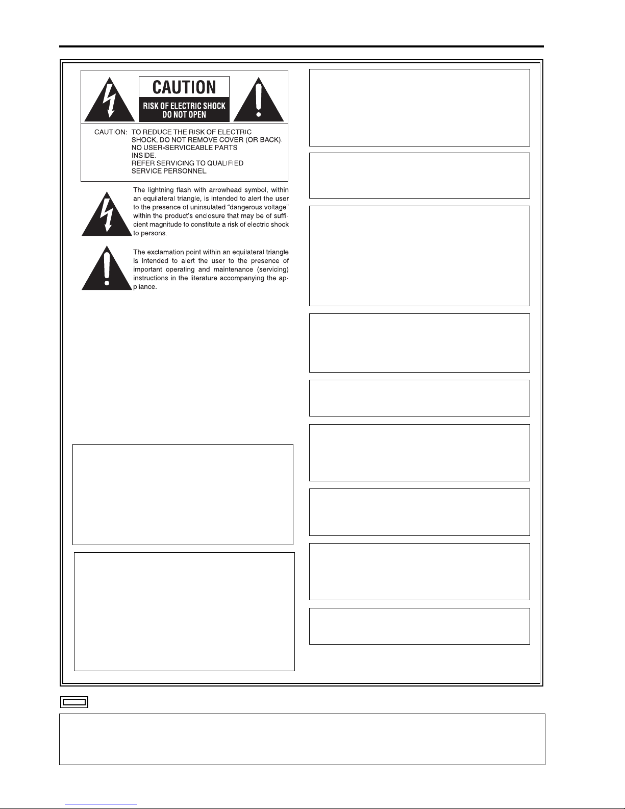
indicates safety information.
■ THIS EQUIPMENT MUST BE GROUNDED
To ensure safe operation, the three-pin plug must be
inserted only into a standard three-pin power outlet
which is effectively grounded through normal
household wiring. Extension cords used with the
equipment must have three cores and be correctly
wired to provide connection to the ground. Wrongly
wired extension cords are a major cause of fatalities.
The fact that the equipment operates satisfactorily
does not imply that the power outlet is grounded or that
the installation is completely safe. For your safety, if
you are in any doubt about the effective grounding of
the power outlet, please consult a qualified electrician.
CAUTION:
THE MAINS PLUG OF THE POWER SUPPLY CORD
SHALL REMAIN READILY OPERABLE.
THE AC RECEPTACLE (MAINS SOCKET OUTLET)
SHALL BE INSTALLED NEAR THE EQUIPMENT
AND SHALL BE EASILY ACCESSIBLE. TO
COMPLETELY DISCONNECT THIS EQUIPMENT
FROM THE AC MAINS, DISCONNECT THE POWER
CORD PLUG FROM THE AC RECEPTACLE.
WARNING:
• TO REDUCE THE RISK OF FIRE OR SHOCK
HAZARD, DO NOT EXPOSE THIS EQUIPMENT
TO RAIN OR MOISTURE.
• TO REDUCE THE RISK OF FIRE OR SHOCK
HAZARD, KEEP THIS EQUIPMENT AWAY
FROM ALL LIQUIDS. USE AND STORE ONLY
IN LOCATIONS WHICH ARE NOT EXPOSED
TO THE RISK OF DRIPPING OR SPLASHING
LIQUIDS, AND DO NOT PLACE ANY LIQUID
CONTAINERS ON TOP OF THE EQUIPMENT.
CAUTION:
In order to maintain adequate ventilation, do not
install or place this unit in a bookcase, built-in
cabinet or any other confined space. To prevent
risk of electric shock or fire hazard due to
overheating, ensure that curtains and any other
materials do not obstruct the ventilation.
CAUTION:
TO REDUCE THE RISK OF FIRE OR SHOCK
HAZARD AND ANNOYING INTERFERENCE, USE
THE RECOMMENDED ACCESSORIES ONLY.
CAUTION:
This apparatus can be operated at a voltage in the
range of 100 - 240 V AC. Voltages other than 120 V
are not intended for U.S.A. and Canada.
CAUTION:
Operation at a voltage other than 120 V AC may
require the use of a different AC plug. Please contact
either a local or foreign Panasonic authorized service
center for assistance in selecting an alternate AC plug.
CAUTION:
This Monitor is for use only with Panasonic Wall
Mount Adaptor, BT-WMA26G. Use with other Wall
Mount is capable of resulting in instability causing
possible injury.
CAUTION:
Excessive sound pressure from earphones and
headphones can cause hearing loss.
WARNING:
Installation should only be performed by qualified
installation personnel.
Improper installation may result in the entire
apparatus falling down and causing injury.
CAUTION:
Check the installation at least once a year.
An improper installation could cause the monitor to
fall off resulting in personal injury.
CAUTION:
Remove the wall mount adaptor when not used.
Otherwise people moving in the vicinity of the
monitor could get caught on the bracket and be
injured.
AC Adapter
The rating plate is on the underside of the AC
Adapter.
Notice (U.S.A. only):
This product has a fluorescent lamp that contains mercury. Disposal may be regulated in your community due to
environmental considerations. For disposal or recycling information, please contact your local authorities, or the
Electronic Industries Alliance: http://www.eiae.org.

3
Read this first ! (for BT-LH2550P) (continued)
FCC NOTICE (USA)
IMPORTANT SAFETY INSTRUCTIONS
1) Read these instructions.
2) Keep these instructions.
3) Heed all warnings.
4) Follow all instructions.
5) Do not use this apparatus near water.
6) Clean only with dry cloth.
7) Do not block any ventilation openings. Install in accordance with the manufacturer’s instructions.
8) Do not install near any heat sources such as radiators, heat registers, stoves, or other apparatus (including amplifiers) that produce heat.
9) Do not defeat the safety purpose of the polarized or grounding-type plug. A polarized plug has two blades
with one wider than the other. A grounding-type plug has two blades and a third grounding prong. The
wide blade or the third prong are provided for your safety. If the provided plug does not fit into your outlet,
consult an electrician for replacement of the obsolete outlet.
10) Protect the power cord from being walked on or pinched particularly at plugs, convenience receptacles,
and the point where they exit from the apparatus.
11) Only use attachments/accessories specified by the manufacturer.
12) Use only with the cart, stand, tripod, bracket, or table specified by the manufacturer, or sold
with the apparatus. When a cart is used, use caution when moving the cart/apparatus combination to avoid injury from tip-over.
13) Unplug this apparatus during lightning storms or when unused for long periods of time.
14) Refer all servicing to qualified service personnel. Servicing is required when the apparatus
has been damaged in any way, such as power-supply cord or plug is damaged, liquid has been spilled or
objects have fallen into the apparatus, the apparatus has been exposed to rain or moisture, does not operate normally, or has been dropped.
Declaration of Conformity
Model Number: BT-LH2550P
Trade Name: Panasonic
Responsible Party: Panasonic Corporation of North America
One Panasonic Way, Secaucus, NJ07094
Support contact: Panasonic Broadcast & Television Systems Company
1-800-524-1448
This device complies with Part 15 of FCC Rules.
Operation is subject to the following two conditions:
(1) This device may not cause harmful interference, and (2) this device must accept any interference
received, including interference that may cause undesired operation.
To assure continued compliance, follow the attached installation instructions and do not make any unauthorized modifications.
Note:
This equipment has been tested and found to comply with the limits for a class B digital device, pursuant to
Part 15 of the FCC Rules. These limits are designed to provide reasonable protection against harmful interference in a residential installation. This equipment generates, uses, and can radiate radio frequency
energy, and if not installed and used in accordance with the instructions, may cause harmful interference to
radio communications. However, there is no guarantee that interference will not occur in a particular installation. If this equipment does cause harmful interference to radio or television reception, which can be
determined by turning the equipment off and on, the user is encouraged to try to correct the interference by
one of the following measures:
• Reorient or relocate the receiving antenna.
• Increase the separation between the equipment and receiver.
• Connect the equipment into an outlet on a circuit different from that to which the receiver is connected.
• Consult the dealer or an experienced radio/TV technician for help.
The user may find the booklet “Something About Interference” available from FCC local regional offices helpful.
Warning:
To assure continued FCC emission limit compliance, follow the attached installation instructions and the user
must use only shielded interface cables when connecting to host computer or peripheral devices. If DVI-D port
is to be used it must connected to PC by compatible interface cable with two ferrite cores. Also, any
unauthorized changes or modifications to this equipment could void the user’s authority to operate this device.
S3125A
4
indicates safety information.
■ THIS EQUIPMENT MUST BE EARTHED
To ensure safe operation, the three-pin plug
must be inserted only into a standard three-pin
power point which is effectively earthed through
normal house-hold wiring.
Extension cords used with the equipment must
have three cores and be correctly wired to
provide connection to the earth. Wrongly wired
extension cords are a major cause of fatalities.
The fact that the equipment operates
satisfactorily does not imply that the power point
is earthed or that the installation is completely
safe. For your safety, if you are in any doubt
about the effective earthing of the power point,
please consult a qualified electrician.
■ DO NOT REMOVE PANEL COVERS BY
UNSCREWING THEM.
To reduce the risk of electric shock, do not
remove covers. No user serviceable parts
inside.
Refer servicing to qualified service personnel.
CAUTION:
THE MAINS PLUG OF THE POWER SUPPLY
CORD SHALL REMAIN READILY OPERABLE.
THE AC RECEPTACLE (MAINS SOCKET OUTLET)
SHALL BE INSTALLED NEAR THE EQUIPMENT
AND SHALL BE EASILY ACCESSIBLE. TO
COMPLETELY DISCONNECT THIS EQUIPMENT
FROM THE AC MAINS, DISCONNECT THE POWER
CORD PLUG FROM THE AC RECEPTACLE.
WARNING:
• TO REDUCE THE RISK OF FIRE OR SHOCK
HAZARD, DO NOT EXPOSE THIS EQUIPMENT
TO RAIN OR MOISTURE.
• TO REDUCE THE RISK OF FIRE OR SHOCK
HAZARD, KEEP THIS EQUIPMENT AWAY
FROM ALL LIQUIDS. USE AND STORE ONLY
IN LOCATIONS WHICH ARE NOT EXPOSED
TO THE RISK OF DRIPPING OR SPLASHING
LIQUIDS, AND DO NOT PLACE ANY LIQUID
CONTAINERS ON TOP OF THE EQUIPMENT.
CAUTION:
TO REDUCE THE RISK OF FIRE OR SHOCK
HAZARD AND ANNOYING INTERFERENCE, USE
THE RECOMMENDED ACCESSORIES ONLY.
CAUTION:
In order to maintain adequate ventilation, do not
install or place this unit in a bookcase, built-in
cabinet or any other confined space. To prevent
risk of electric shock or fire hazard due to
overheating, ensure that curtains and any other
materials do not obstruct the ventilation.
CAUTION:
This Monitor is for use only with Panasonic Wall
Mount Adaptor, BT-WMA26G. Use with other Wall
Mount is capable of resulting in instability causing
possible injury.
CAUTION:
Excessive sound pressure from earphones and
headphones can cause hearing loss.
WARNING:
Installation should only be performed by qualified
installation personnel.
Improper installation may result in the entire
apparatus falling down and causing injury.
CAUTION:
Check the installation at least once a year.
An improper installation could cause the monitor to
fall off resulting in personal injury.
CAUTION:
Remove the wall mount adaptor when not used.
Otherwise people moving in the vicinity of the
monitor could get caught on the bracket and be
injured
AC Adapter
The rating plate is on the underside of the AC
Adapter.
Read this first ! (for BT-LH2550E)
5
Read this first ! (for BT-LH2550E) (continued)
indicates safety information.
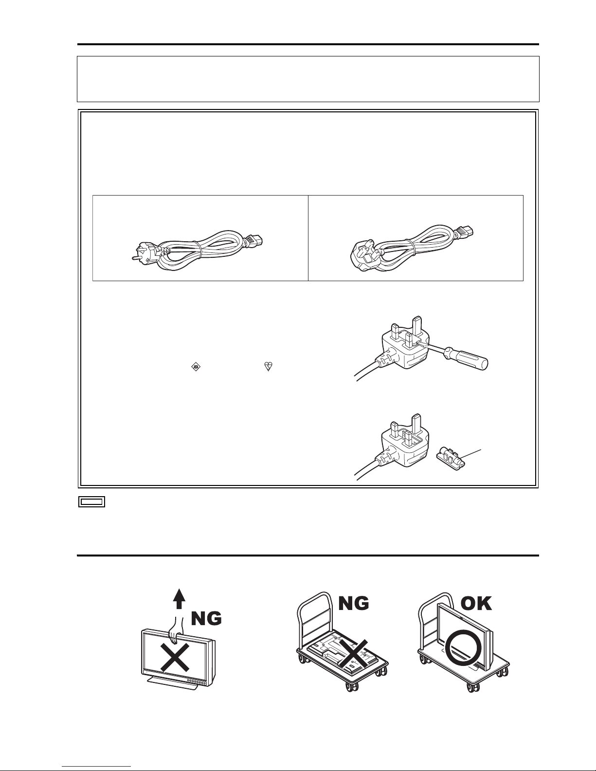
Transportation precautions
Do not expose the LCD panel to strong pressure or pressure from pointed objects. Take care especially during
transportation.
Exposing the LCD panel to strong pressure may result in blurring or other damage.
Operating precaution
Operation near any appliance which generates strong magnetic fields may give rise to noise in the video and
audio signals. If this should be the case, deal with the situation by, for instance, moving the source of the magnetic
fields away from the unit before operation.
FOR U.K. ONLY
This appliance is supplied with a moulded three pin
mains plug for your safety and convenience.
A 13 amp fuse is fitted in this plug.
Should the fuse need to be replaced please ensure that
the replacement fuse has a rating of 13 amps and that it
is approved by ASTA or BSI to BS1362.
Check for the ASTA mark or the BSI mark
on the
body of the fuse.
If the plug contains a removable fuse cover you must
ensure that it is refitted when the fuse is replaced.
If you lose the fuse cover the plug must not be used
until a replacement cover is obtained.
A replacement fuse cover can be purchased from your
local Panasonic Dealer.
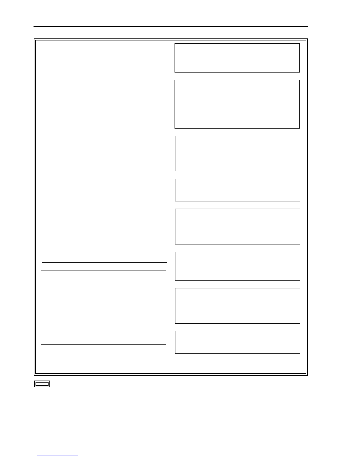
Caution for AC Mains Lead
FOR YOUR SAFETY PLEASE READ THE FOLLOWING TEXT CAREFULLY.
This product is equipped with 2 types of AC mains cable. One is for continental Europe, etc. and the other one is only
for U.K.
Appropriate mains cable must be used in each local area, since the other type of mains cable is not suitable.
FOR CONTINENTAL EUROPE, ETC.
Not to be used in the U.K.
FOR U.K. ONLY
How to replace the fuse
1.Open the fuse compartment with a screwdriver.
2.Replace the fuse.
Fuse
Do not try to lift the
monitor by grabbing
the panel.
Do not place the monitor face down during transportation to prevent
damaging it. Keep it upright.

6
Read this first !
EMC NOTICE FOR THE PURCHASER/USER OF THE APPARATUS
1. Applicable standards and operating environment (BT-LH2550E)
The apparatus is compliant with:
• standards EN55103-1 and EN550103-2 1996.and
• electromagnetic environments E1, E2, E3 and E4
2. Pre-requisite conditions to achieving compliance with the above standards
<1> Peripheral equipment to be connected to the apparatus and special connecting cables
• The purchaser/user is urged to use only equipment which has been recommended by us as
peripheral equipment to be connected to the apparatus.
• The purchaser/user is urged to use only the connecting cables described below.
<2> For the connecting cables, use shielded cables which suit the intended purpose of the
apparatus.
• Video signal connecting cables
Use double shielded coaxial cables, which are designed for 75-ohm type high-frequency applications,
for SDI (Serial Digital Interface).
Coaxial cables, which are designed for 75-ohm type high-frequency applications, are recommended
for analog video signals.
• Audio signal connecting cables
If your apparatus supports AES/EBU serial digital audio signals, use cables designed for AES/EBU.
Use shielded cables, which provide quality performance for high-frequency transmission applications,
for analog audio signals.
• Other connecting cables (IEEE1394, USB)
Use shielded cables, which provide quality performance for high-frequency applications, as
connecting cables.
• When connecting to the DVI signal terminal, use a cable with a ferrite core.
• If your apparatus is supplied with ferrite core(s), they must be attached on cable(s) following
instructions in this manual.
3. Performance level
The performance level of the apparatus is equivalent to or better than the performance level required by
these standards.
However, the apparatus may be adversely affected by interference if it is being used in an EMC environment,
such as an area where strong electromagnetic fields are generated (by the presence of signal transmission
towers, cellular phones, etc.). In order to minimize the adverse effects of the interference on the apparatus in
cases like this, it is recommended that the following steps be taken with the apparatus being affected and
with its operating environment:
1. Place the apparatus at a distance from the source of the interference.
2. Change the direction of the apparatus.
3. Change the connection method used for the apparatus.
4. Connect the apparatus to another power outlet where the power is not shared by any other
appliances.

7
• The LCD screen is manufactured to precise specifications. Although over 99.99% of the pixels function normally,
0.01% of the pixels are either missing or constantly lit (red, blue or green). This is normal and not a cause for
concern.
• The liquid crystal protection panel is a specially manufactured component. Wiping it with a hard cloth, or rubbing
it vigorously will scratch the surface.
• If a still image is displayed for an extended period of time, it may generate a temporary afterimage (phosphor
burn-in). (However, such images can be removed by displaying normal video for a while.)
• The response speed and brightness of liquid crystal vary with ambient temperatures.
• Let authorized service person handle installation.
Be sure to consult with the service person about the installation. Make sure that the wall is strong enough to
endure the weight of this unit including the mount fittings. If not strong enough, it may fall off resulting in injury.
• Do not install the unit in a place exposed to direct sunlight, as it may damage the cabinet and the LCD screen.
• Do not install the unit in locations where enough space cannot be provided around it as heat may build up inside
preventing normal operation. Be sure to provide enough space around the unit.
• Exposing the LCD screen to intense light sources will impair its characteristics and lower image quality.
• In an environment exposed to drastic temperature fluctuations, condensation may build up on and inside the
LCD screen. This may lower the quality of the screen and may damage it.
• Some video images may appear blurred on the screen.
• Leaving the unit in a location exposed to high temperature and humidity for an extended period of time may
damage the LCD screen and cause blurring.
Contents
Read this first ! . . . . . . . . . . . . . . . . . . . . . . . . . . . . . 2
Transportation precautions . . . . . . . . . . . . . . . . . . . 5
Precautions for Use . . . . . . . . . . . . . . . . . . . . . . . . . 7
Standard accessories . . . . . . . . . . . . . . . . . . . . . . . 7
Optional units . . . . . . . . . . . . . . . . . . . . . . . . . . . . . . 7
Outline . . . . . . . . . . . . . . . . . . . . . . . . . . . . . . . . . . . . 8
Dimensions . . . . . . . . . . . . . . . . . . . . . . . . . . . . . . . . 9
Controls and Their Functions . . . . . . . . . . . . . . . . 10
Video monitor unit ..................................................10
Front panel controls ...............................................11
Rear panel terminals..............................................12
AC Adapter.............................................................13
Power Supply. . . . . . . . . . . . . . . . . . . . . . . . . . . . . . 14
How to Use the On Screen Menu . . . . . . . . . . . . . . 15
User Data . . . . . . . . . . . . . . . . . . . . . . . . . . . . . . . . . 20
Main Menu . . . . . . . . . . . . . . . . . . . . . . . . . . . . . . . . 21
Menu configuration ................................................21
MARKER................................................................22
Marker types ..........................................................24
VIDEO CONFIG .....................................................26
SYSTEM CONFIG .................................................29
FUNCTION.............................................................32
GPI .........................................................................35
INPUT SELECT .....................................................36
AUDIO....................................................................38
DISPLAY SETUP ...................................................39
CONTROL..............................................................45
HOURMETER ........................................................45
REMOTE Specifications . . . . . . . . . . . . . . . . . . . . . 48
Maintenance inspecions. . . . . . . . . . . . . . . . . . . . . 52
Maintenance . . . . . . . . . . . . . . . . . . . . . . . . . . . . . . 52
Error Display . . . . . . . . . . . . . . . . . . . . . . . . . . . . . . 52
Specifications . . . . . . . . . . . . . . . . . . . . . . . . . . . . . 53
Standard accessories
<For BT-LH2550P>
Power cord × 1
Power cord hook × 1
Screw × 1 (for securing power cord)
AC Adaptor × 1
DC cord × 1
CD-ROM × 1
<For BT-LH2550E>
AC mains lead × 2
AC mains lead hook × 1
Screw × 1 (for securing power cord)
AC Adaptor × 1
DC cord × 1
CD-ROM × 1
Optional units
Wall Mount Adaptor BT-WMA26G (Leave installation of the wall mount adaptor to authorized personnel.)
Precautions for Use

8
The BT-LH2550 LCD monitor is a 25.5 inch full HD LCD display panel designed especially for broadcasting service
and business use.
■ Compact 25.5 type full HD monitor
• The monitor is equipped with a high-resolution (1920 x 1200) IPS LCD panel.
• Efforts to develop a small footprint have resulted in a surprisingly compact design for a monitor with a screen
size of 25.5 inches.
■ Wide color gamut panel and 10-bit 3D LUT for faithful color reproduction
• The wide color gamut panel increases the origin coordinate accuracy of broadcast standard RGB and 3D LUT
improves color reproduction. It is also compatible with the wide color gamut modes for the Adobe RGB and DCinema standards *
1
.
*1 D-Cinema refers to D-Cinema min. Color Gamut.
■ A new image processing engine for improved video quality
• 10-bit image processing accurately and smoothly reproduces color from low to high brightness levels.
• Built-in I/P converter circuit with a delay of less than 1 field minimizes the delay between input signal to picture
display.
• Diagonal line compensation processing circuit reduces vertical image degradation and jagged noise in the
diagonal direction.
• High-speed motion response results in crisp image reproduction without blurring.
• The gamma correction of each monitor is set individually prior to shipment.
■ Multi-format image compatibility
• This monitor is equipped with SDI (HD/SD compatible), VIDEO, YP
BPR/RGB, DVI-D (HDCP compatible) input jacks.
• It supports both NTSC and PAL TV broadcast systems.
■ A host of functions
• Split-screen function
You can display two selected inputs in two windows and set a separate color space and gamma value for image
comparison.
• Time code display
During HD SDI input, you can select to display VITC, LTC or UB time code.
• Closed caption
During VIDEO (NTSC) input, this feature displays the closed caption information embedded in the video signal.
(EIA-608 compliant)
• Waveform and vector display
This feature shows the waveform (for SDI, VIDEO and YP
BPR inputs) and vector display (for SDI input) of input signals.
• Cross hatch overlay function
Displays markers at regular vertical and horizontal intervals to facilitate composition.
■ Calibration function
The monitor can easily be calibrated using a luminance meter.
■ REMOTE control
Depending on the intended use of the monitor, you can select between parallel remote control (GPI) and serial
remote control (RS232C).
• Adobe is the registered trademark or trademark of Adobe System Incorporated in the United States and other
countries. Other company names and product names are the trademarks or registered trademarks of their
respective owners.
Outline
9
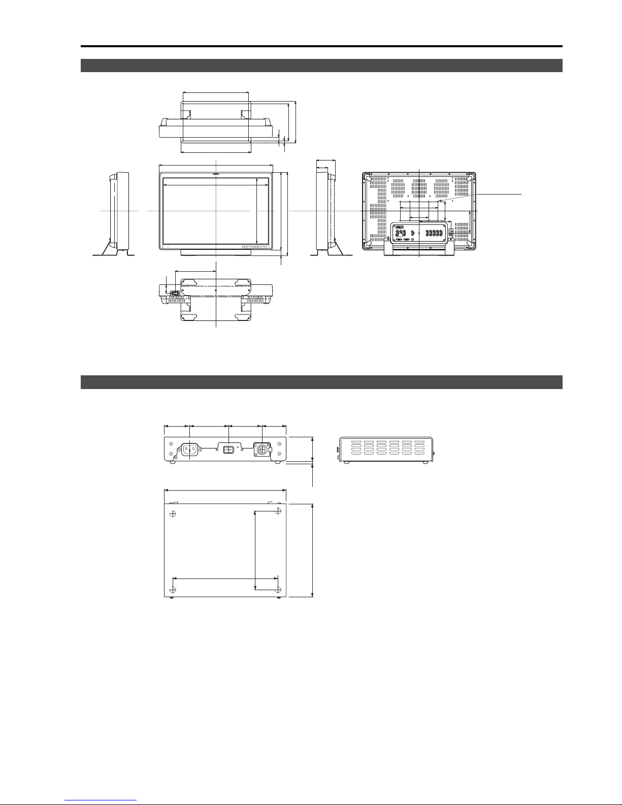
Video monitor unit
AC Adaptor
10-M4,L=10mm Max
46 (1.8)
215 (8.5)
60 (2.4)
100 (3.9)
200 (7.9)
169 (6.7)
100 (3.9)
100 (3.9)
116.5 (4.6)
220 (8.7)
196 (7.7)
12 (0.5)
18 (0.7)
370 (14.6)
346 (13.6)
440 (17.3)
30 (1.2)
410 (16.1)
599 (23.6)
343.8 (13.5)
550.08 (21.7)
• When installing the monitor in one place permanently, we
recommend that you fix the monitor in place using the
screw holes in the lower part of the stand.
Unit
: mm (inches
)
46 (1.8)64 (2.5)73.5 (2.9)48.5 (1.9)
150 (5.9)
200 (7.9)
232 (9.1)
4.5 (0.2) 46 (1.8)
177 (7.0)
Uni
t: mm (inches
)
• The rating plate is on the underside of the AC Adapter.
Dimensions
10
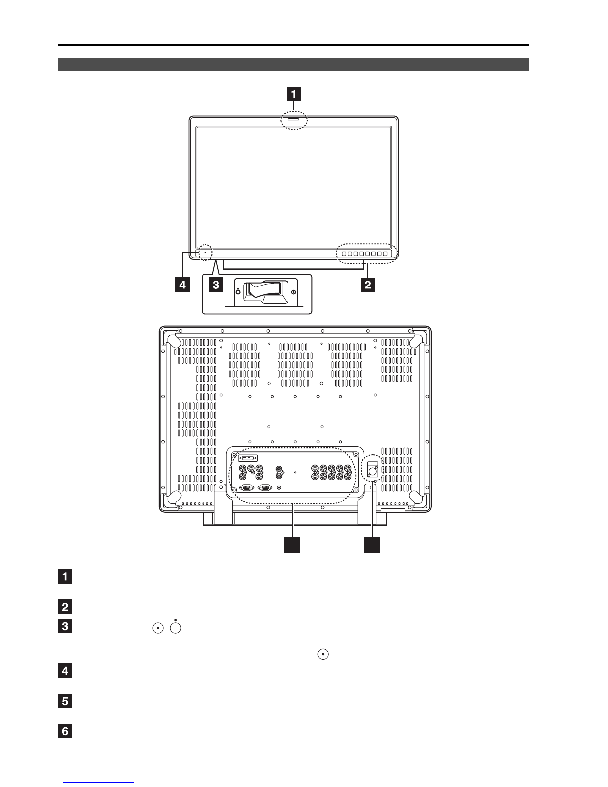
Tally lamp (page 35, 48)
The color of the tally lamp Indicates monitor status.
Front panel controls (page 11)
POWER switch ( / )
The POWER switch is located at the bottom of the front panel.
This switch turns the power On and Off. Set the switch to to turn it on.
Power LED
When the power is turned on, the LED lights green.
DC IN
Connect the supplied DC cord of the supplied AC adapter to this terminal.
Rear panel terminals (page 12)
Video monitor unit
6 5
Front view
Rear view
Controls and Their Functions
11
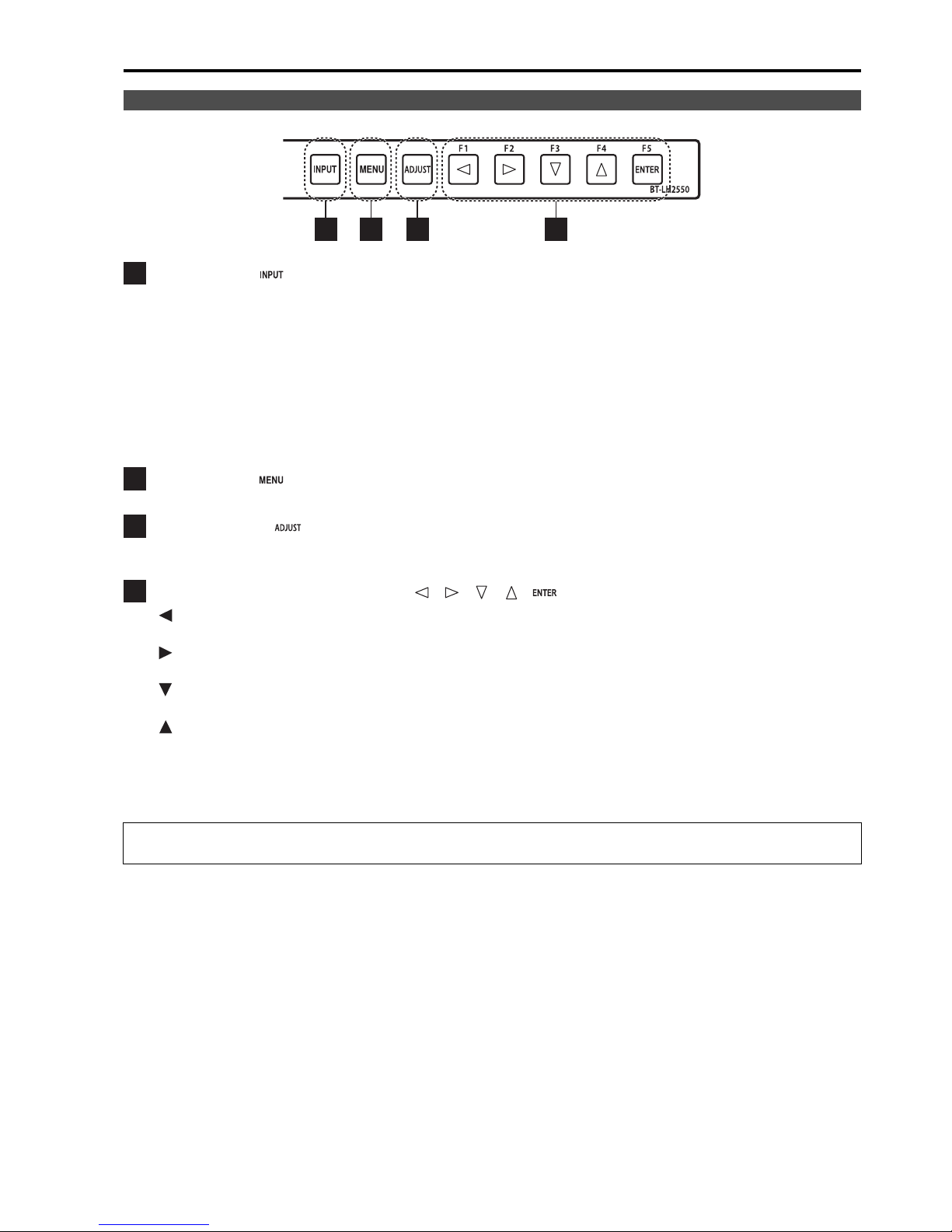
INPUT button ( )
Selects the signal input line.
Each press of the button changes the lines in the following order: VIDEO SDI1 SDI2 YP
BPR/RGB
DVI-D.
VIDEO : VIDEO input
SDI1 : Serial digital interface input (HD/SD compatible)
SDI2 : Serial digital interface input (HD/SD compatible)
YP
BPR/RGB : Analog component input (YPBPR) or RGB input also compatible with RGB input from a PC.
DVI-D : DVI-D input (HDCP compatible)
• When the power is turned on, the input line used when the power was last turned off is selected.
The INPUT menu can be set to skip input lines that are not used.
MENU button ( )
Press to open a menu, exit a menu or return to a previous menu.
ADJUST button ( )
Press to display the picture/volume adjusting menu (PHASE, CHROMA, BRIGHT, B.LIGHT [BACKLIGHT] or
CONT. [CONTRAST], VOLUME).
Cursor, ENTER, FUNCTION buttons ( , , , , )
/FUNCTION1 : Moves the cursor to the left. Use to select the picture/volume adjusting menu or to
confirm a menu item assigned to the FUNCTION1.
/FUNCTION2 : Moves the cursor to the right. Use to select the picture/volume adjusting menu or to
confirm a menu item assigned to the FUNCTION2.
/FUNCTION3 : Moves the cursor downwards. Use to select the picture/volume adjusting menu or to
confirm a menu item assigned to the FUNCTION3.
/FUNCTION4 : Moves the cursor upwards. Use to select the picture/volume adjusting menu or to
confirm a menu item assigned to the FUNCTION4.
ENTER/FUNCTION5 : Confirms a menu selection and opens a submenu. It also confirms a menu item
assigned to the FUNCTION5.
• When the control lock is on, the key mark appears and FUNCTION does not operate.
Front panel controls
The buttons are made of plastic film. Do not use pointed objects such as fingernails, pens or screwdrivers to press
the buttons as the resulting damage or deformation could prevent proper contact.
7
8
9
10
7
8
9
10
Controls and Their Functions (continued)
12
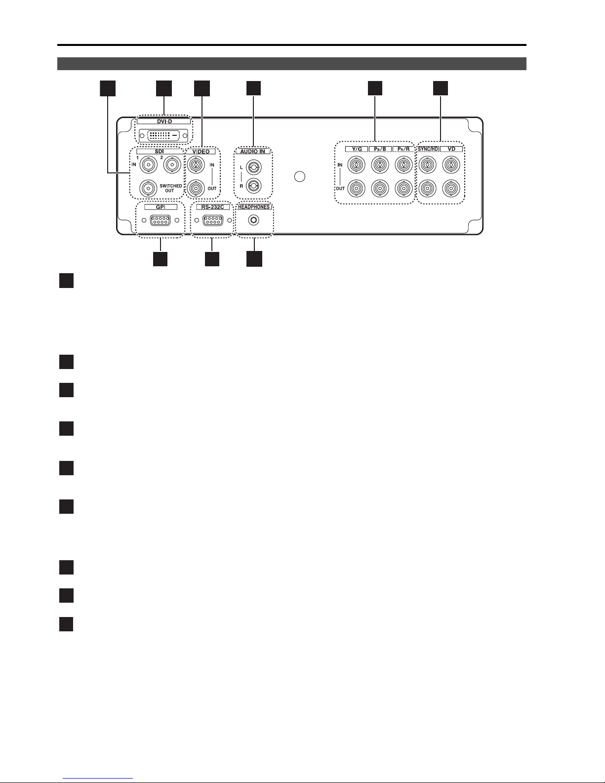
SDI (HD/SD) terminal (BNC)
IN1 : This is the SDI input terminal (compatible with HD/SD automatic switching).
IN2 : This is the SDI input terminal (compatible with HD/SD automatic switching).
SWITCHED OUT : This is the active through-out terminal for the SDI input signal being displayed on the
screen.
• Active SDI through-out is only output when [SDI1] or [SDI2] is selected using the [INPUT] button. It is not
output when something other than SDI is selected. This terminal supports embedded audio.
DVI-D terminal (DVI-D)
An HDCP compliant DVI-D signal input terminal.
VIDEO terminal (BNC)
*1
IN : This is the VIDEO signal (composite signal) input terminal.
OUT : This is the input signal through-out terminal.
AUDIO IN terminal
This is the common audio input terminal for all video input terminals.
• SDI input audio is automatically selected by selecting [SDI1] or [SDI2] with [INPUT SELECT].
YP
BPR/RGB terminal (BNC)
*1*3
IN : This is the YPBPR/RGB signal input terminal.
OUT : This is the input signal through-out terminal.
SYNC/HD, VD terminal (BNC)
*2
IN : This is the input terminal for external synchronizing SYNC/HD, VD signals.
OUT : This is the input signal through-out terminal.
• When using RGB signals from a PC, connect the horizontal synchronizing signal to the SYNC/HD terminal,
and the vertical synchronizing signal to the VD terminal.
GPI input terminal (D-SUB 9-pin)
External control is possible by using a GPI signal.
RS232C terminal (D-SUB 9-pin)
External control is possible by using an RS232 signal.
HEADPHONES output connector (stereo mini-jack M3)
Connect a pair of headphones to monitor the sound.
• The sound volume and sound quality will depend on the headphones.
*1 Unless a cable is connected to the OUT terminal, the IN terminal is automatically terminated at 75Ω.
Since a connection to the OUT terminal releases the 75Ω termination of the unit, the level of the VIDEO signal
input to the unit may become too large depending on the connected device.
*2 Unless a cable is connected to the OUT terminal, the IN terminal is automatically terminated at 1 kΩ. Making a
connection to the OUT terminal will automatically release the 1 kΩ termination.
*3 When a device is connected to the OUT terminal, 1080P and PC input and other broadband signals may distort
character outlines and other details.
Rear panel terminals
11 12
19
13
18
15 16
17
14
11
12
13
14
15
16
17
18
19
Controls and Their Functions (continued)
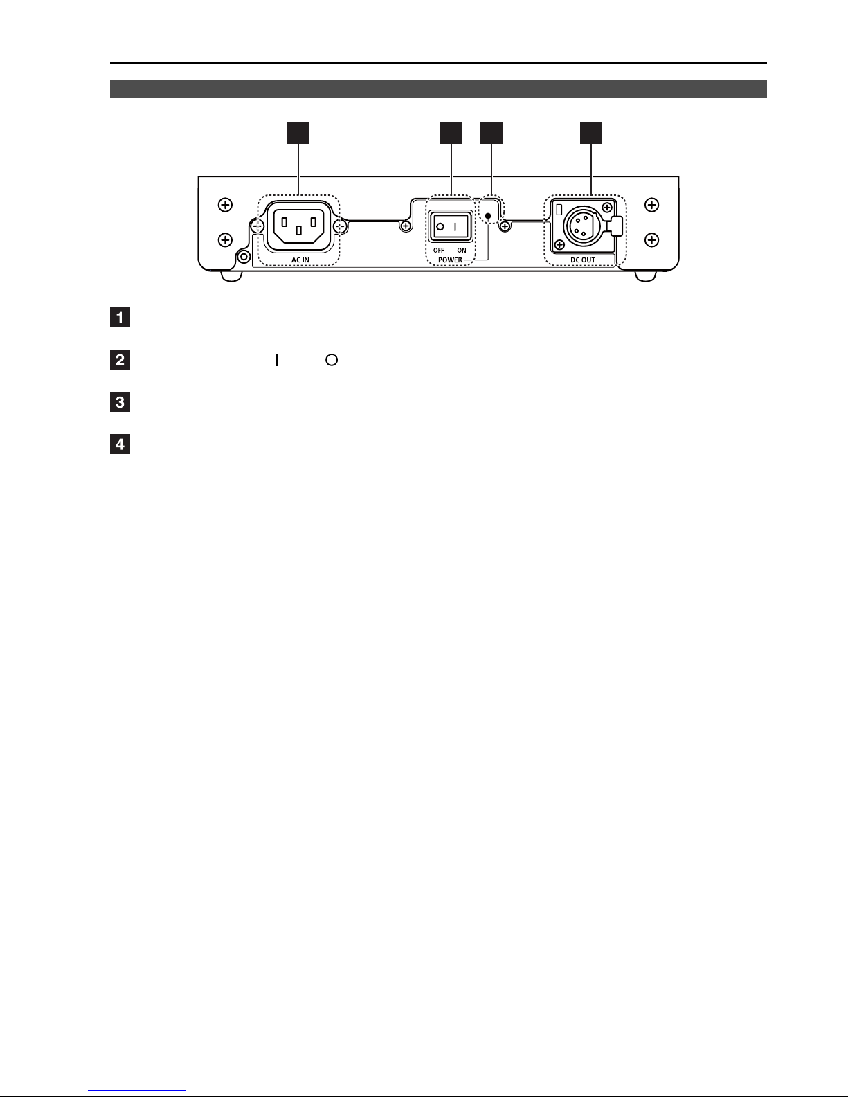
13
AC IN (AC inlet)
This is the AC input terminal.
POWER switch (ON : , OFF : )
This switch turns the AC adapter on and off.
POWER lamp
This lamp lights green when the POWER switch is set to on.
DC OUT
This is the DC output terminal.
This terminal enables connection of a DC cord.
AC Adapter
2 3 41
Controls and Their Functions (continued)
14
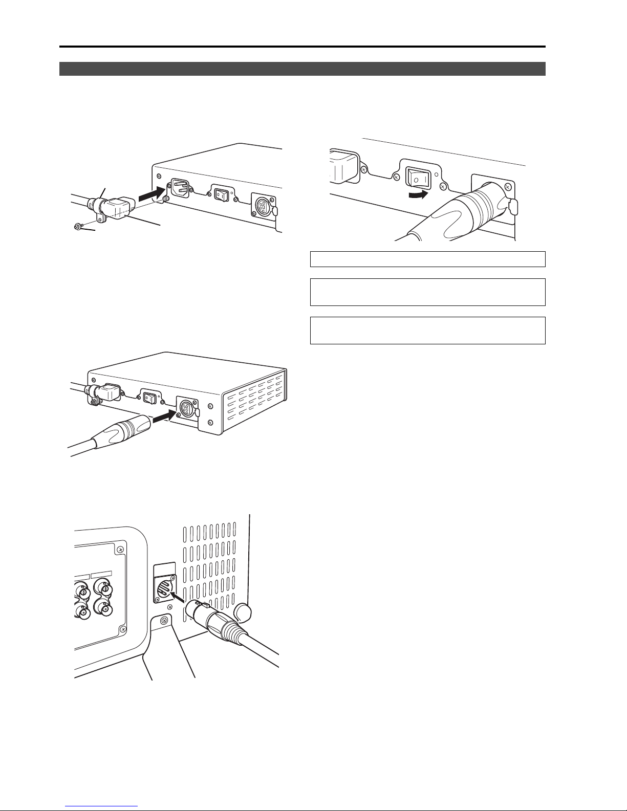
Power Supply
1. Connect the power cord to the AC inlet of the AC
adapter.
Use the supplied screw (for securing power cord)
and the power cord hook to secure the power cord to
the AC adapter.
2. Slide the supplied DC cord into the DC OUT
terminal on the AC adapter until it is locked in
place.
3. Slide the DC cord into the DC IN terminal on the
unit until it locks in place.
4. Connect the power cord to an AC outlet.
5. Turn on the POWER switch. The POWER LED
lights green.
Connecting the power cord
Power cord hook
Screw
Power cord
Be sure to use the supplied AC adapter.
Do not use the supplied AC adapter for powering
other devices.
The AC adapter generates heat during use, which is
normal and not a cause for concern.
15
How to Use the On Screen Menu
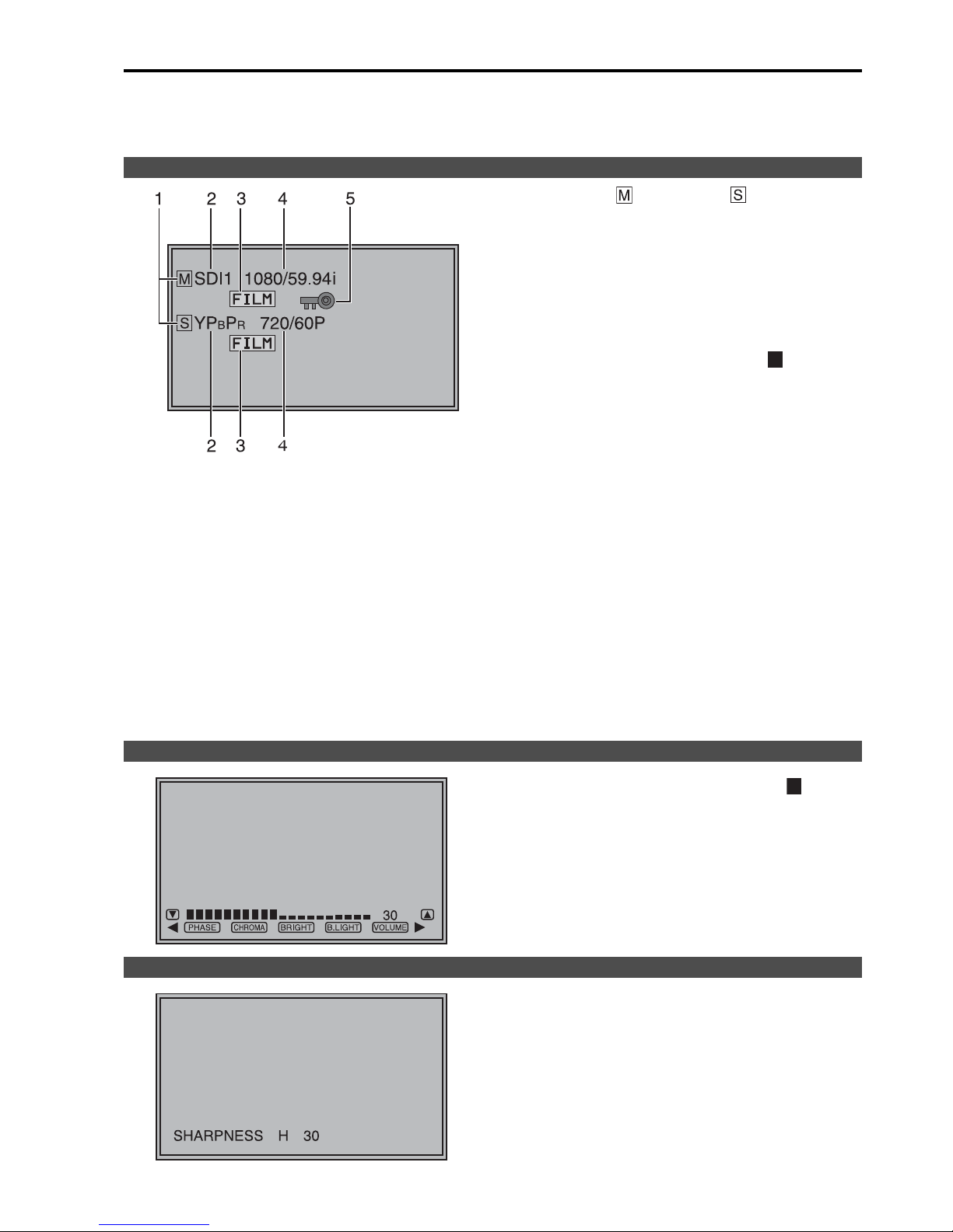
The screen displays eight types of information: input signal status, picture/volume adjusting menu status,
sharpness display, FUNCTION display, audio level meter display, menu display, TIME CODE display and CLOSED
CAPTION display.
1. Main window , sub-window indication
• Indicates whether the main window or sub-window
is displayed.
• In split screen display, the screen synchronized to
the reference sync changes with the input signal
format and “TWO WINDOW SIZE” settings
(
page
44
)
.
The screen synchronized to the reference sync is
displayed in white and the screen that is not
synchronized is displayed in yellow.
2. The selected input line ( page 11, )
• VIDEO, SDI1, SDI2,
YP
BPR/RGB-VIDEO/RGB-COMP.
DVI-VIDEO/DVI-COMP.
• Use “STATUS DISPLAY” in the “SYSTEM CONFIG”
menu to set the display status
(
page 29).
3. Various indications (FILM mode)
• This indicates that “GAMMA SELECT” is set to
“FILM” in the “VIDEO CONFIG” menu.
4. Signal format
•
Use “STATUS DISPLAY” in the “SYSTEM CONFIG”
menu to set the display status (
page 29).
• “UNSUPPORT SIGNAL” appears if an unsupported
signal is input. It may also indicate that the format
selected in the “INPUT SELECT
”
menu does not
match the input signal.
• “NO SIGNAL
”
appears if no signal is input.
Note:
“UNSUPPORT SIGNAL
”
and “NO SIGNAL” may not
be properly displayed.
5. Various indications (Lock status)
• This indicates that “CONTROL” is set to “REMOTE”
in the “CONTROL” menu.
• Press the ADJUST button ( page 11, ) to open
the picture/volume adjusting menu.
• To clear the display, press the ADJUST button again,
press the MENU button or leave it idle for 10
seconds.
• Only adjustments that appear on the screen can be
adjusted.
• The display always appears in the same screen
location.
• This is the SHARPNESS H/V mode display.
• It disappears after 2 minutes of inaction.
Input signal status
7
Picture/volume adjusting menu
9
Sharpness display
16
• Use the menu to open and set up functions.
• When “FUNCTION DISPLAY” ( page 32) is set to
ON, press any of the "FUNCTION1" to "FUNCTION5"
buttons to display the functions assigned to
FUNCTION buttons.
• This display disappears after 2 seconds of inaction.
• “XXXXX” indicates operating status ( page 34,
“Functions displayed during FUNCTION button
operation”).
• A white skeleton bar meter indicates the audio level
for SDI signals.
• You can switch the level display on/off and set the
number of displayed channels using the menu
( page 38, “AUDIO”).
• The 0 dB line and channel display can be switched
on/off from the menu ( page 38, “AUDIO”).
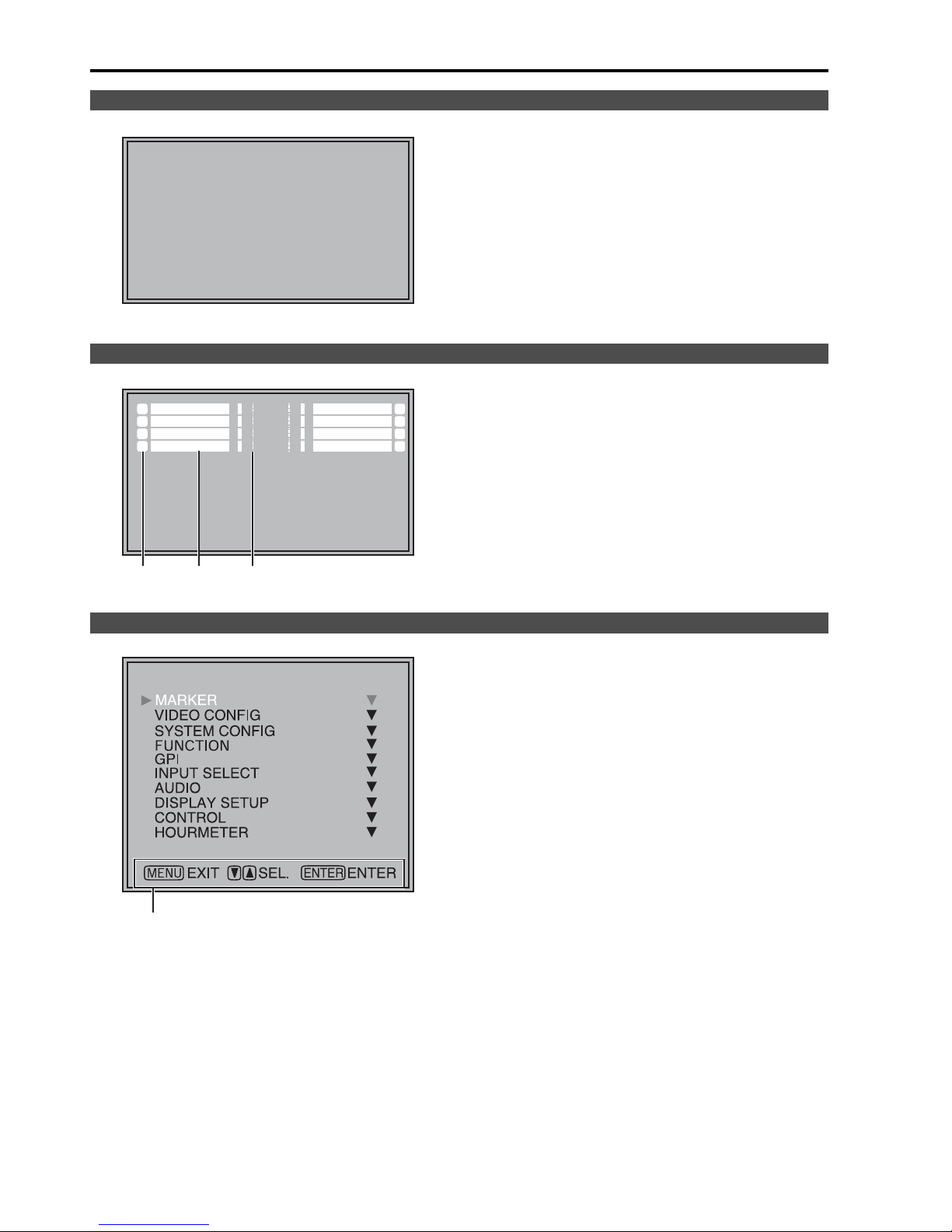
• This is the menu display.
• It disappears after 2 minutes of inaction.
• You can change position of the display ( page 29,
“MENU POSITION”).
FUNCTION display
F1:MARKER
F2:WFM/VECTOR
F3:TWO WINDOW
F4:TIME CODE
F5:LEVEL METER
XXXXX
Audio level meter display
11
33
55
77
22
44
66
88
Channel
display
Level
display
0 dB line
Menu display
[MAIN MENU]
Displays instructions on menu
button operations.
How to Use the On Screen Menu (continued)
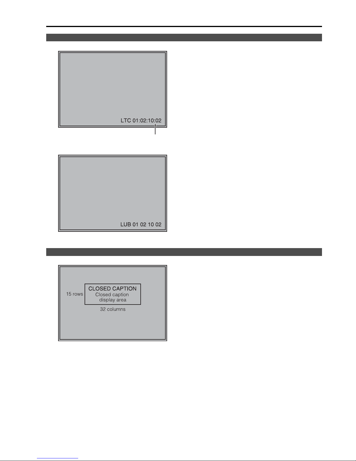
17
• Use the menu to display and set the time code for
HD-SDI signal input. It also allows you to switch
display mode (VITC, LTC, VUB, LUB).
In VITC and LTC display mode:
• Displays the time code in hours: minutes: seconds:
or frames.
• In drop-frame mode, a different delimiter between
seconds and frames is used.
Note:
Read errors are displayed as “--:--:--:--”
In VUB and LUB display modes:
• BG8, BG7, BG6, BG5, BG4, BG3, BG2, BG1 appear
in the stated order. BG: binary group
• The (:) delimiter does not appear.
Note:
Read errors are displayed as “--:--:--:--”
• Display position and character size can be modified
( page 39, “POSITION” and “FONT SIZE” in the
“DISPLAY SETUP” menu).
• Use the menu to display and set closed caption
display for VIDEO (NTSC) signals. It also allows you
to select display mode (CC1 to CC4) ( page 39,
“CLOSED CAPTION” and “MODE SELECT” in the
“DISPLAY SETUP” menu.).
Note:
Closed captions are not available during HV DELAY.
In split-screen display, closed captions appear only
when a VIDEO input line is displayed in the main
window.
TIME CODE display (TC)
( : ) NDF
( . ) DF
CLOSED CAPTION (CC) display
How to Use the On Screen Menu (continued)
 Loading...