

Page 1
Operating Instructions
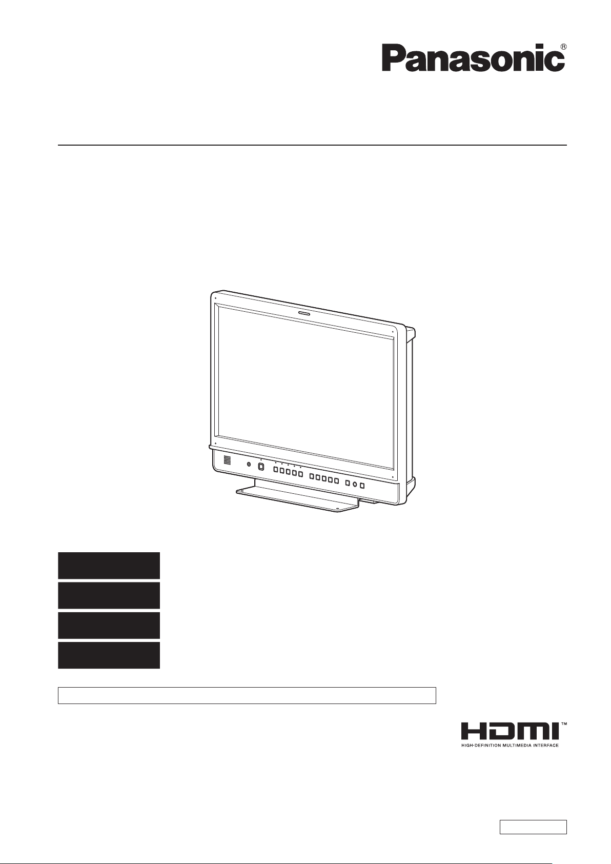
LCD Video Monitor
Model No.
Model No.
BT-LH2170P
BT-LH2170E
DEUTSCH
FRANÇAIS
ITALIANO
ESPAÑOL
This manual is also contained as a PDF file on the CD-ROM supplied with the unit. (Back cover)
Before operating this product, please read the instructions carefully and save this manual for future use.
SS0812KT0 -PS
Printed in Japan
Für Erlauterungen in Deutsch, konsultieren Sie bitte die mitgelieferte CD-ROM.
(Zurück Decke)
Pour des explications en français, veuillez vous reporter au CD-ROM fourni.
(Quatrième de couverture)
Per le istruzioni in italiano, vedere il CD-ROM in dotazione. (Retro della copertina)
Para la explicación en español, consulte el CD-ROM suministrado. (Cubierta trasera)
ENGLISH
VQT4M18
Page 2

3
Read this first ! (for BT-LH2170P)
CAUTION:
The mains plug of the power supply cord shall remain
readily operable.
The AC receptacle (mains socket outlet) shall be installed
near the equipment and shall be easily accessible. To
completely disconnect this equipment from the AC mains,
disconnect the power cable plug from the AC receptacle.
CAUTION:
In order to maintain adequate ventilation, do not install or
place this unit in a bookcase, built-in cabinet or any other
confined space. To prevent risk of electric shock or fire
hazard due to overheating, ensure that curtains and any
other materials do not obstruct the ventilation.
CAUTION:
To reduce the risk of fire or electric shock and annoying
interference, use the recommended accessories only.
CAUTION:
This apparatus can be operated at a voltage in the range
of 100 - 240 V AC. Voltages other than 120 V are not
WARNING:
This equipment must be grounded.
To ensure safe operation, the three-pin plug must be
inserted only into a standard three-pin power outlet which
is effectively grounded through normal household wiring.
Extension cords used with the equipment must have three
cores and be correctly wired to provide connection to
the ground. Wrongly wired extension cords are a major
cause of fatalities. The fact that the equipment operates
satisfactorily does not imply that the power outlet is
grounded or that the installation is completely safe. For
your safety, if you are in any doubt about the effective
grounding of the power outlet, please consult a qualified
electrician.
WARNING:
• To reduce the risk of fire or electric shock, do not expose
this equipment to rain or moisture.
• To reduce the risk of fire or electric shock hazard, keep
this equipment away from all liquids. Use and store
only in locations which are not exposed to the risk of
dripping or splashing liquids, and do not place any liquid
containers on top of the equipment.
intended for U.S.A. and Canada.
CAUTION:
Excessive sound pressure from earphones and
headphones can cause hearing loss.
CAUTION:
This Monitor is for use only with Panasonic Wall Mount
Adaptor, BT-WMA17G. Use with other Wall Mount or Rack
Mount Adaptor is capable of resulting in instability causing
possible injury.
CAUTION:
Check the installation at least once a year.
An improper installation could cause the monitor to fall off
resulting in personal injury.
CAUTION:
Remove the wall mount adaptor when not used.
Otherwise people moving in the vicinity of the monitor
could get caught on the bracket and be injured.
WARNING:
Always keep the stand screws and protective panel
mounting screws out of the reach of infants and small
children.
WARNING:
Installation should only be performed by qualified
installation personnel.
Improper installation may result in the entire apparatus
falling down and causing injury.
indicates safety information.
Notice (U.S.A. only):
Disposal may be regulated in your community due to Environmental considerations. For disposal or recycling information, please
visit Panasonic website: http://www.panasonic.com/environmental or call 1-888-769-0149.
2
Page 3

Read this first ! (for BT-LH2170P) (continued)
FCC NOTICE (USA)
This device complies with part 15 of the FCC Rules. Operation is subject to the following two conditions:
(1) This device may not cause harmful interference, and (2) this device must accept any interference received, including
interference that may cause undesired operation
CAUTION:
This equipment has been tested and found to comply with the limits for a class A digital device, pursuant to Part 15 of the
FCC Rules. These limits are designed to provide reasonable protection against harmful interference when the equipment is
operated in a commercial environment. This equipment generates, uses, and can radiate radio frequency energy and, if not
installed and used in accordance with the instruction manual, may cause harmful interference to radio communications.
Operation of this equipment in a residential area is likely to cause harmful interference in which case the user will be required
to correct the interference at his own expense.
Warning:
To assure continued FCC emission limit compliance, the user must use only shielded interface cables when connecting to
external units. Also, any unauthorized changes or modifications to this equipment could void the user’s authority to operate it.
indicates safety information.
IMPORTANT SAFETY INSTRUCTIONS
1) Read these instructions.
2) Keep these instructions.
3) Heed all warnings.
4) Follow all instructions.
5) Do not use this apparatus near water.
6) Clean only with dry cloth.
7) Do not block any ventilation openings. Install in accordance with the manufacturer’s instructions.
8) Do not install near any heat sources such as radiators, heat registers, stoves, or other apparatus (including amplifiers) that
produce heat.
9) Do not defeat the safety purpose of the polarized or grounding-type plug. A polarized plug has two blades with one wider than the
other. A grounding-type plug has two blades and a third grounding prong. The wide blade or the third prong are provided for your
safety. If the provided plug does not fit into your outlet, consult an electrician for replacement of the obsolete outlet.
10) Protect the power cable from being walked on or pinched particularly at plugs, convenience receptacles, and the point where they
exit from the apparatus.
11) Only use attachments/accessories specified by the manufacturer.
12) Use only with the cart, stand, tripod, bracket, or table specified by the manufacturer, or sold with the apparatus.
When a cart is used, use caution when moving the cart/apparatus combination to avoid injury from tip-over.
13) Unplug this apparatus during lightning storms or when unused for long periods of time.
14) Refer all servicing to qualified service personnel. Servicing is required when the apparatus has been damaged
in any way, such as power-supply cord or plug is damaged, liquid has been spilled or objects have fallen into the
apparatus, the apparatus has been exposed to rain or moisture, does not operate normally, or has been dropped.
Page 4
5
Read this first ! (for BT-LH2170E)
WARNING:
This equipment must be earthed.
To ensure safe operation, the three-pin plug must be
inserted only into a standard three-pin power point which
is effectively earthed through normal household wiring.
Extension cords used with the equipment must have
three cores and be correctly wired to provide connection
to the earth. Wrongly wired extension cords are a major
cause of fatalities. The fact that the equipment operates
satisfactorily does not imply that the power point is earthed
or that the installation is completely safe. For your safety,
if you are in any doubt about the effective earthing of the
power point, please consult a qualified electrician.
WARNING:
• To reduce the risk of fire or electric shock, do not expose
this equipment to rain or moisture.
• To reduce the risk of fire or electric shock hazard, keep
this equipment away from all liquids. Use and store
only in locations which are not exposed to the risk of
dripping or splashing liquids, and do not place any liquid
containers on top of the equipment.
WARNING:
Always keep the stand screws and protective panel
mounting screws out of the reach of infants and small
children.
WARNING:
Installation should only be performed by qualified
installation personnel.
Improper installation may result in the entire apparatus
falling down and causing injury.
CAUTION:
The mains plug of the power supply cord shall remain
readily operable.
The AC receptacle (mains socket outlet) shall be installed
near the equipment and shall be easily accessible. To
completely disconnect this equipment from the AC mains,
disconnect the power cable plug from the AC receptacle.
CAUTION:
To reduce the risk of fire or electric shock and annoying
interference, use the recommended accessories only.
CAUTION:
In order to maintain adequate ventilation, do not install or
place this unit in a bookcase, built-in cabinet or any other
confined space. To prevent risk of electric shock or fire
hazard due to overheating, ensure that curtains and any
other materials do not obstruct the ventilation.
CAUTION:
Excessive sound pressure from earphones and
headphones can cause hearing loss.
CAUTION:
This Monitor is for use only with Panasonic Wall Mount
Adaptor, BT-WMA17G. Use with other Wall Mount or Rack
Mount Adaptor is capable of resulting in instability causing
possible injury.
CAUTION:
Check the installation at least once a year.
An improper installation could cause the monitor to fall off
resulting in personal injury.
CAUTION:
Do not remove panel covers by unscrewing them.
To reduce the risk of electric shock, do not remove covers.
No user serviceable parts inside.
Refer servicing to qualified service personnel.
indicates safety information.
EEE Yönetmeliğine Uygundur.
EEE Complies with Directive of Turkey.
[ India Only ]
For the purpose of recycling to facilitate effective utilization of resources, please return this product to a nearby
authorized collection center, registered dismantler or recycler, or Panasonic service center when disposing of this
product.
Please see the Panasonic website for further information on collection centers, etc.
http://www.panasonic.co.in/wps/portal/home
CAUTION:
Remove the wall mount adaptor when not used.
Otherwise people moving in the vicinity of the monitor
could get caught on the bracket and be injured.
4
Page 5
Read this first ! (for BT-LH2170E) (continued)
Caution for AC Mains Lead
FOR YOUR SAFETY PLEASE READ THE FOLLOWING TEXT CAREFULLY.
This product is equipped with 2 types of AC mains cable. One is for continental Europe, etc. and the other one is only
for U.K.
Appropriate mains cable must be used in each local area, since the other type of mains cable is not suitable.
FOR CONTINENTAL EUROPE, ETC.
Not to be used in the U.K.
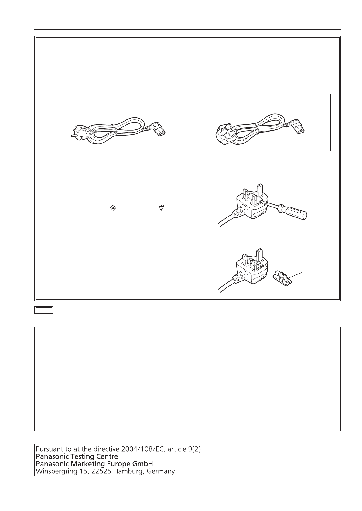
FOR U.K. ONLY
FOR U.K. ONLY
This appliance is supplied with a moulded three pin
mains plug for your safety and convenience.
A 13 amp fuse is fitted in this plug.
Should the fuse need to be replaced please ensure that
the replacement fuse has a rating of 13 amps and that it
is approved by ASTA or BSI to BS1362.
Check for the ASTA mark or the BSI mark
body of the fuse.
If the plug contains a removable fuse cover you must
ensure that it is refitted when the fuse is replaced.
If you lose the fuse cover the plug must not be used
until a replacement cover is obtained.
A replacement fuse cover can be purchased from your
local Panasonic Dealer.
on the
How to replace the fuse
1.Open the fuse compartment with a screwdriver.
2.Replace the fuse.
Fuse
indicates safety information.
Note regarding the Power Management function specified under COMMISSION REGULATION (EC)
No 1275/2008 implementing Directive 2009/125/EC of the European Parliament and of the Council.
This device is designed and manufactured for use at a broadcasting station and/or in a similar environment.
This device is not equipped with a Power Management function or the Power Management function is set to OFF as it will
prevent the device from fulfilling its intended purpose for the reasons below.
1. If the device is a Studio Camera, a Weather Camera, a Mixer or other processor:
A Power Management function may cause the device to suddenly stop during recording or while On Air.
2. If the device is a Studio Monitor:
A Power Management function may cause video for the confirmation of whether a signal is normal, or whether the signal has
been lost, to be un-viewable.
3. If the device is a Camera Recorder:
A professional camera recorder must be able to start quickly at any time, but a Power Management function will cause an
increase in the time taken to resume from Stand-by mode.
Page 6

Read this first ! (for BT-LH2170E) (continued)
EMC NOTICE FOR THE PURCHASER/USER OF THE APPARATUS
1. Applicable standards and operating environment
The apparatus is compliant with:
• standards EN55103-1 and EN55103-2 2009, and
• electromagnetic environments E1, E2, E3 and E4.
2. Pre-requisite conditions to achieving compliance with the above standards
<1> Peripheral equipment to be connected to the apparatus and special connecting cables
• The purchaser/user is urged to use only equipment which has been recommended by us as peripheral equipment to be
connected to the apparatus.
• The purchaser/user is urged to use only the connecting cables described below.
<2> For the connecting cables, use shielded cables which suit the intended purpose of the apparatus.
• Video signal connecting cables
Use double shielded coaxial cables, which are designed for 75-ohm type high-frequency applications, for SDI (Serial
Digital Interface).
Coaxial cables, which are designed for 75-ohm type high-frequency applications, are recommended for analog video
signals.
• Audio signal connecting cables
If your apparatus supports AES/EBU serial digital audio signals, use cables designed for AES/EBU.
Use shielded cables, which provide quality performance for high-frequency transmission applications, for analog audio
signals.
• Other connecting cables (IEEE1394, USB)
Use shielded cables, which provide quality performance for high-frequency applications, as connecting cables.
• When connecting to the DVI signal terminal, use a cable with a ferrite core.
• If your apparatus is supplied with ferrite core(s), they must be attached on cable(s) following instructions in this manual.
3. Performance level
The performance level of the apparatus is equivalent to or better than the performance level required by these standards.
However, the apparatus may be adversely affected by interference if it is being used in an EMC environment, such as an
area where strong electromagnetic fields are generated (by the presence of signal transmission towers, cellular phones, etc.).
In order to minimize the adverse effects of the interference on the apparatus in cases like this, it is recommended that the
following steps be taken with the apparatus being affected and with its operating environment:
1. Place the apparatus at a distance from the source of the interference.
2. Change the direction of the apparatus.
3. Change the connection method used for the apparatus.
4. Connect the apparatus to another power outlet where the power is not shared by any other appliances.
Декларація про Відповідність
Вимогам Технічного Регламенту Обмеження Використання деяких Небезпечних Речовин в електричному та електронному
обладнанні
(затвердженого Постановою №1057 Кабінету Міністрів України)
Виріб відповідає вимогам Технічного Регламенту Обмеження Використання деяких Небезпечних Речовин в електричному та
електронному обладнанні (ТР ОВНР).
Вміст небезпечних речовин у випадках, не обумовлених в Додатку №2 ТР ОВНР, :
1. свинець(Pb) – не перевищує 0,1 % ваги речовини або в концентрації до 1000 частин на мільйон;
2. кадмій (Cd)– не перевищує 0,01 % ваги речовини або в концентрації до 100 частин на мільйон;
3. ртуть(Hg) – не перевищує 0,1 % ваги речовини або в концентрації до 1000 частин на мільйон;
4. шестивалентний хром (Cr6+ ) – не перевищує 0,1 % ваги речовини або в концентрації до 1000 частин на мільйон;
5. полібромбіфеноли (PBB) – не перевищує 0,1% ваги речовини або в концентрації до 1000 частин на мільйон;
6. полібромдефенілові ефіри (PBDE) – не перевищує 0,1 % ваги речовини або в концентрації до 1000 частин на мільйон.
6
Page 7
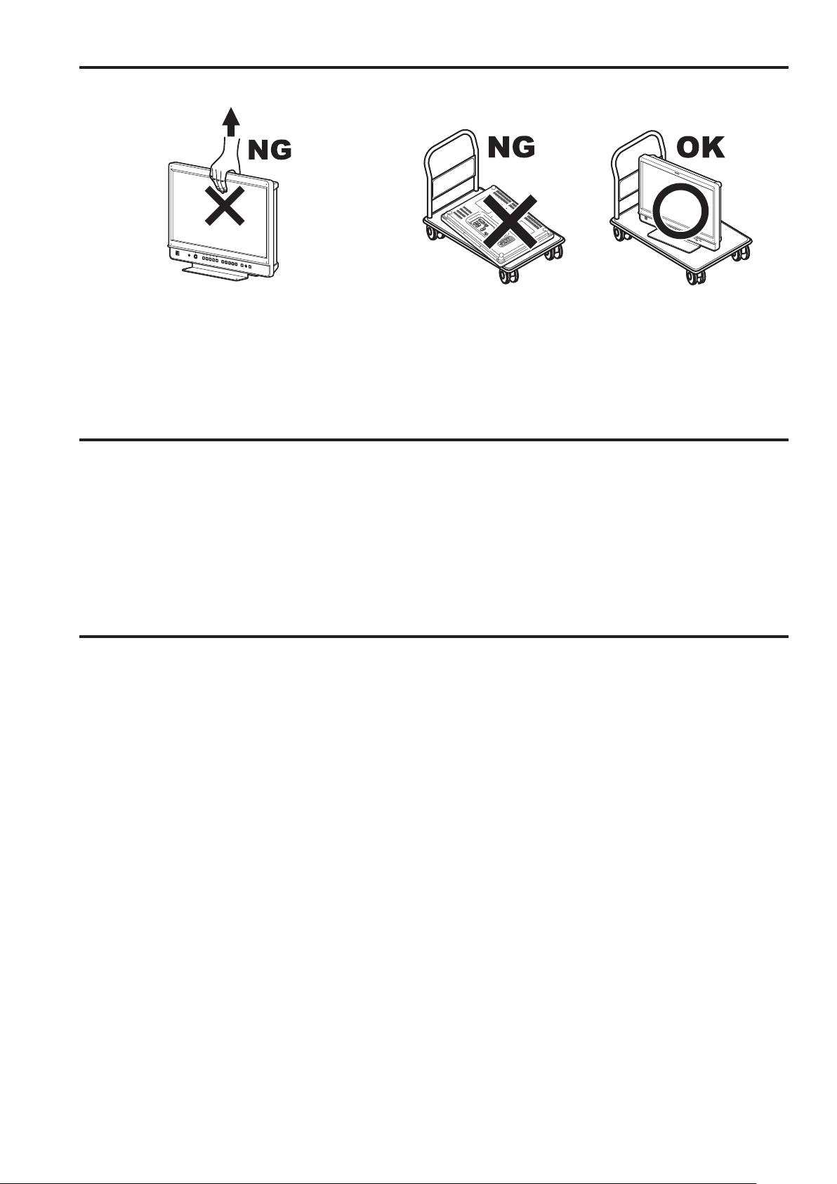
Transportation precautions
Do not try to lift the monitor by grabbing the LCD panel. Do not place the monitor face down during transportation to prevent
damaging it. Keep it upright.
Do not expose the LCD panel to strong pressure or pressure from pointed objects. Take care especially during transportation.
Exposing the LCD panel to strong pressure may result in blurring or other damage.
About this instruction manual
• This instruction manual refers to BT-LH2170P/BT-LH2170E as “this unit.”
• The illustrations, explanatory drawings, and other figures included in this instruction manual are for illustrative purposes only and
may differ from actual appearance.
• HDMI, the HDMI logo, and High-Definition Multimedia Interface are trademarks or registered trademarks of HDMI Licensing, LLC in
the United States and/or other countries.
• Adobe
• Page references are indicated as (→ page 00) in this manual.
®
Reader® is a trademark of Adobe Systems Incorporated.
Precautions for Use
• The LCD monitor is manufactured with high-precision technology and has an effective pixel count of over 99.99 %. However, less than 0.01 % of pixels may be stuck or dead. This is
not a malfunction and does not affect recorded images.
• When a still image is displayed for an extended period of time,
it may generate a temporary afterimage (phosphor burn-in).
(However, such images can be removed by displaying normal
video for a while.)
• LCD response speed and brightness vary with ambient temperatures.
• Do not install the unit where it is exposed to direct sunlight. It
may damage the cabinet and LCD screen.
• Leaving the unit in a location exposed to high temperature and
humidity for an extended period of time may damage the LCD
screen and cause blurring.
• Streaks of light may be seen in the area between the edge of
the screen and the frame; this is normal and not a malfunction.
• The LCD panel is covered by the packaging material to protect
it from damage during transportation and when unpacking it.
Remove the packaging material before use.
• This unit does not support VIERA Link. When the unit is connected to a VIERA-Link-compatible device via an HDMI cable,
VIERA Link functions on the other devices may not operate
properly.
• Do not install the unit in locations where enough space cannot
be provided around it as heat may build up inside preventing
normal operation. Be sure to provide enough space around
the unit.
• Exposing the LCD screen to intense light sources will impair
its characteristics and lower image quality.
• In an environment exposed to drastic temperature fluctuations,
condensation may build up on and inside the LCD screen.
This may lower the quality of the screen and may damage it.
• Some video images may appear blurred on the screen.
• Using the unit near a wireless transmitter, high-voltage equipment, speakers, large motors or other devices or exposing it
to static electricity could cause electromagnetic interference
and distort audio and video reception.
7
Page 8

9
Table of Contents
Read this first ! (for BT-LH2170P) ...........................................2
Read this first ! (for BT-LH2170E) ...........................................4
Transportation precautions .....................................................7
About this instruction manual .................................................7
Precautions for Use..................................................................7
Standard accessories · Optional units ...................................9
Outline .......................................................................................9
Dimensions .............................................................................10
Controls and Their Functions ...............................................11
Video monitor ........................................................................11
Front panel ............................................................................12
Rear panel .............................................................................13
Power supply ..........................................................................14
Connecting the power cable ..................................................14
Detaching and Attaching the Stand ......................................15
Detaching the stand ..............................................................15
Attaching the stand ................................................................15
On-screen Display ..................................................................16
Operating status display ........................................................16
Main menu (MAIN MENU)/FUNCTION menu/
INPUT SELECT menu displays .........................................16
Picture adjusting (PICTURE) menu display ..........................17
Audio volume display ............................................................17
Sharpness display .................................................................17
FUNCTION display ................................................................17
Audio volume bar meter display ............................................18
Time code (TC) display .........................................................18
Closed caption (CC) display ..................................................19
IMD (in monitor display) display ............................................19
How to Use the On Screen Menu ..........................................20
Main menu (MAIN MENU) .....................................................20
FUNCTION menu ..................................................................20
INPUT SELECT menu ...........................................................20
Picture adjusting (PICTURE) menu .......................................21
Audio volume .........................................................................21
User Data .................................................................................22
Saving user data ...................................................................22
Loading user data ..................................................................22
Main Menu ...............................................................................23
Menu configuration ................................................................23
2D/3D ASSIST ......................................................................24
MARKER ...............................................................................24
MARKER types .....................................................................26
VIDEO CONFIG ....................................................................27
SYSTEM CONFIG .................................................................30
Performing AUTO CALIBRATION .........................................33
RESET operation ..................................................................33
FUNCTION ............................................................................34
GPI ........................................................................................43
INPUT SELECT .....................................................................44
AUDIO ...................................................................................45
DISPLAY SETUP ..................................................................46
CONTROL .............................................................................48
HOURS METER ....................................................................48
3D Assist Mode .......................................................................49
MIRROR (Left/Right and Top/Bottom inversion) ...................50
SHIFT (Horizontal and Vertical Shift) ....................................50
COMPARISON (Composition Check) ...................................51
CONVERGENCE (Convergence Check) ..............................51
COLOR (Color Check) ..........................................................52
ZOOM FOCUS (Zoom and Focus Check) ............................52
VERTICAL (Vertical Offset Check) ........................................53
OVERLAY (Parallax Check) ..................................................53
Setting Item Restrictions .......................................................55
REMOTE Specifications .........................................................60
GPI input terminal ..................................................................60
RS-232C input terminal .........................................................62
RS-485 input/output terminal .................................................63
Maintenance Inspections .......................................................70
Error and Warning Information .............................................71
Maintenance ............................................................................71
Specifications .........................................................................72
Index ........................................................................................78
8
Page 9

Standard accessories · Optional units
Standard accessories
Power cable x 1 (BT-LH2170P)
Power cable x 2 (BT-LH2170E)
Stand (already attached to the product) x 1
Stand screws (already attached to the product) x 3
CD-ROM x 1
Protection panel mounting screws (8 mm long M3 screws) x 4
• The customer can use these screws for permanent attachment of a protective panel designed for the monitor. (→page 11)
• Tightening torque: Tighten to about 30 N·cm or less
<Note>
After unpacking the monitor, dispose of the AC cord cap (BT-LH2170E only) and packaging material in an appropriate manner.
Optional units
• BT-WMA17G wall mount adapter (Leave installation of the wall mount adapter to authorized personnel.)
Outline
The BT-LH2170P/BT-LH2170E is a compact, flat panel LCD monitor for broadcast and industrial applications, equipped with a
54.6 cm (21.5 inch) (effective display area) LCD display.
High performance LCD panel
This product incorporates a full HD (1920 x 1080) LCD panel.
It offers excellent color reproduction, a wide viewing angle,
and a fast response time.
Superb Moving Image Quality Achieved by New Image
Processing Engine
• A 3D Look Up Table (LUT) and a 10-bit image processing
engine facilitate accurate and smooth gradation from low to
high brightness levels.
• The inclusion of an I/P conversion circuit with a low delay of
less than one field minimizes the delay time between signal
input and monitor display.
• The use of a diagonal line compensation circuit reduces
image degradation in the vertical direction and jagged noise
on diagonal lines.
• The high-speed moving image response time provides vivid
and clear image display.
• Gamma compensation is performed for each monitor.
Includes 3D Assist Functions
Various assist functions are included to allow connecting
the left and right connectors of a 3D camera to the two SDI
inputs and capturing 3D images that are easier to view on a
2D monitor. These functions also make camera adjustments
easier and reduce the preparation time required for 3D shooting.
Wide Variety of Functions and Interfaces
• Equipped with 3G-SDI, SDI (HD/SD compatible), HDMI,
VIDEO, and DVI-I inputs.
• FOCUS-IN-RED function (Displayed abbreviated to F-IN-R
in the [PICTURE] (picture adjusting) menu.)
Focusing the camera is extremely easy because the area of
the image in focus is displayed in red to make it easy to see
what is in focus.
• WFM (Y/R/G/B) and vectorscope display functions
Capable of showing a Y/R/G/B waveform display for input
signals (3G-SDI, SDI, HDMI, VIDEO, and DVI-I inputs) and
a vectorscope display (for 3G-SDI and SDI inputs).
• Audio volume bar meter display function
There are level displays for embedded 3G-SDI, SDI and
HDMI audio signals and analog audio signals. Furthermore,
support is also included for reference point setting, peak
hold, and overrange display.
The incorporation of a speaker and a HEADPHONES output
jack means you can check the audio. There is also a menu
for selecting channels.
• Closed caption function
The captions added to video signals can be displayed during SDI and VIDEO input.
• 2-screen display function
The screen can be split into two to allow you to make a
screen comparison for the same input connectors and same
format. (SUB WINDOW function)
It can display two SDI inputs simultaneously in two
windows. (TWO WINDOW function)
One input signal can be displayed on two windows for
3G-SDI, SDI, HDMI, VIDEO and DVI-I input VIDEO formats
in combination with FOCUS-IN-RED, Y MAP, ZEBRA and
other functions to simplify camera adjustments. (PICTURE
ASSIST function)
• Cross hatch display function
This function displays markers at regular vertical and horizontal intervals to facilitate easy composition.
• External remote control
RS-485, RS-232C and GPI remote control terminals are
provided.
A loop-through connection using the RS-485 input and
output terminals allows control of multiple monitors (up to 32
monitors).
• IMD (in-monitor display) display
The RS-485 interface allows you to display text and the tally
indication on the monitor.
9
Page 10
11
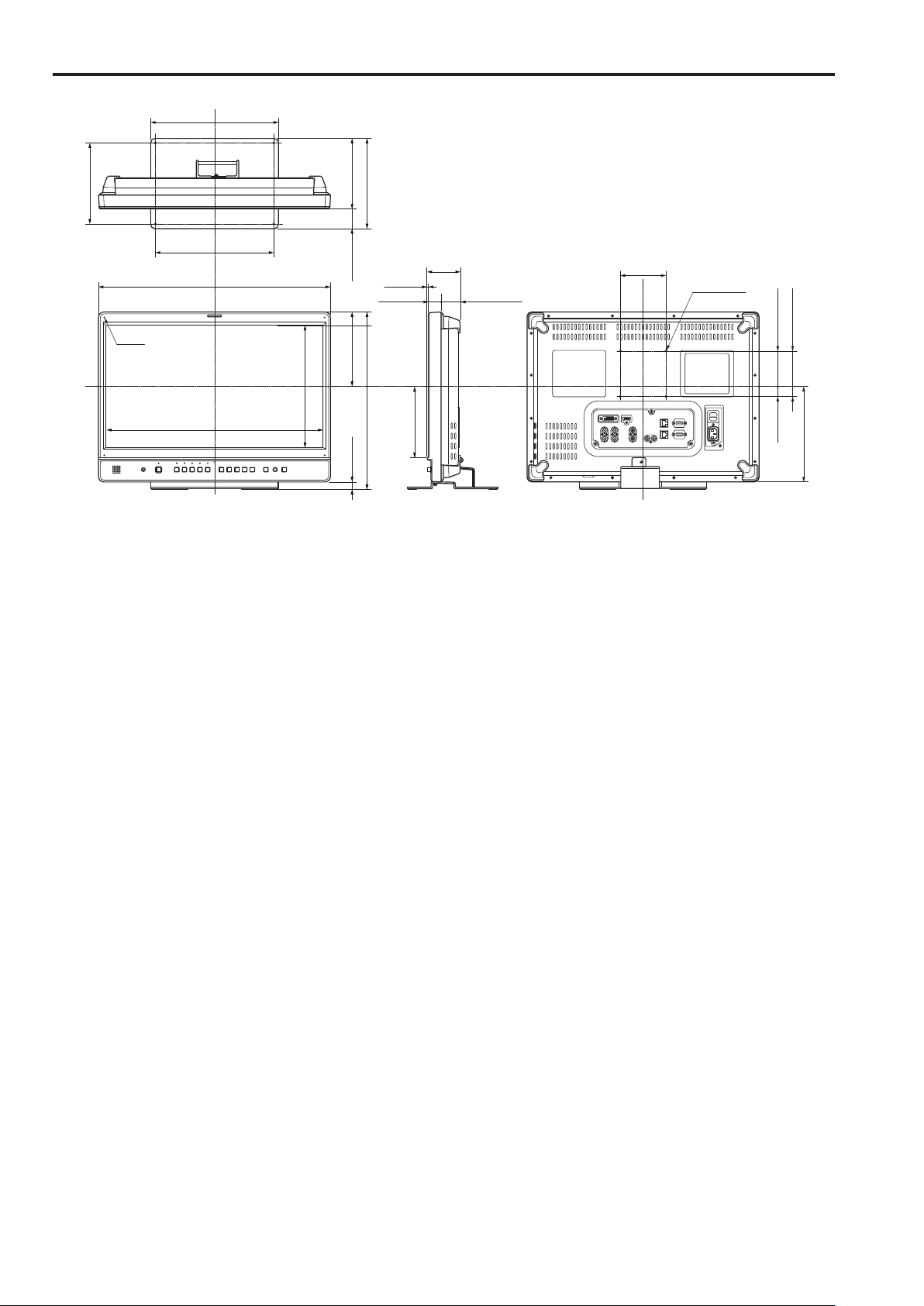
Dimensions
178(7)
Unit: mm (inches)
280(11)
154.9 (6-1/8)43.1 (1-5/8)
198(7-13/16)
4-M3
260(10-1/4)
510(20-1/16)
475.2(18-5/8)
267.3(10-1/2)
2.5(1/8)
27(1-1/16)
163.5(6-7/16)15(9/16)
388(15-1/4)
72
(2-13/16)
156(6-1/8)
42.5(1-5/8)
100
(3-15/16)
4-M4 P=0.7
100(3-15/16)
77.8(3-1/16)22.2(7/8)
209.5(8-1/4)
• When the unit will be permanently installed in one place, we recommend securing it in place using the screw holes at the bottom of
the stand.
10
Page 11

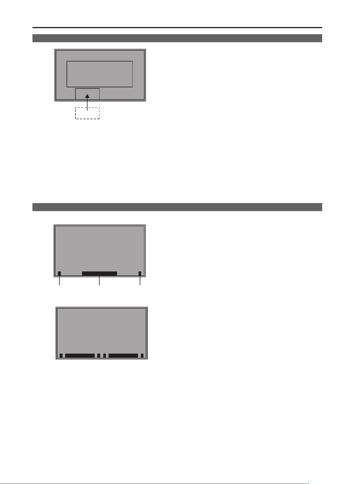
Controls and Their Functions
1 2
Video monitor
Front panel Rear panel
Front panel
(→page 12)
1
Tally Lamp (Red and Green)
Can be lit by a control signal (red tally and green tally) via
GPI.
When both the red and green tally are triggered together,
the lamp lights amber.
2
Protective panel mounting screw holes (4 holes)
Four screw holes have been provided to enable attachment
of a permanent protective panel.
<Note>
The LCD panel is shipped in packaging material to protect it
from damage during unpacking and transportation. Remove
the packaging material before using the monitor.
Rear panel
(→page 13)
Power Supply
(You can switch between AC
and DC (→page 14))
11
Page 12
Controls and Their Functions (continued)
13
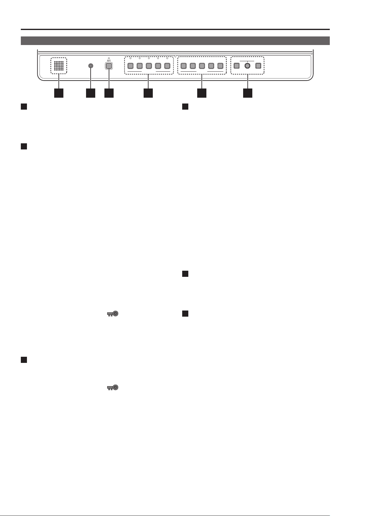
Front panel
HEADPHONES
SDI 1 SDI 2 HDMI DVI-I
VIDEO
INPUT SELECT
5 16 2 3 4
1
POWER <8> switch
Switches the power supply ON/OFF. When the power is on,
the LED (green) lights.
To turn the power off, press and hold the switch for at least
three seconds.
2
INPUT SELECT buttons
Selects the signal input line. The green LED light above the
pressed button indicates the selected input signal.
VIDEO : Video input
SDI1 : Serial digital interface input (compatible with 3G/
HD/SD)
SDI2 : Serial digital interface input (HD/SD compatible)
HDMI : HDMI input (HDCP compatible)
DVI-I : DVI-I input (HDCP compatible)
• When the power is turned on, the input line used when the
• In 3D assist and TWO WINDOW mode, the input is fixed
• Switching the [2D/3D ASSIST] menu from [3D ASSIST] to
• Switching the TWO WINDOW function from ON to OFF
• When the control lock is on, the
• When INT-SG (internal chart for adjustment [Color Bar
3
FUNCTION button
FUNCTION1 to FUNCTION5:
Press to use function assigned to the FUNCTION button
using a menu.
• When the control lock is on, the
• Selects one of the following four input signals:
digital video or PC signal, analog video or PC
signal.(→page 44)
power was last turned off is selected.
to SDI1/SDI2 and the input line cannot be changed. (Then
both the SDI1 and SDI2 LEDs go on.)
[2D] will return the input line to the previous 2D setting.
will return the input line to the previous OFF setting. However, turning on the SUB WINDOW function or the PICTURE ASSIST function when the TWO WINDOW function
is on, activates SDI1 operation, and when the 2-screen
display function is off, the SDI1 input line is used.
mark appears and
input lines cannot be changed.(→page 48)
+ Grayscale]) is selected, all LEDs above the <INPUT
SELECT> button are off. Use the [INPUT SELECT] menu
to select INT-SG. (→page 20)
mark appears to
indicate that FUNCTION operation is disabled.(→page 48)
1 2
3 4 5
FUNCTION
4
MENU button, rotary knob (with push-on switch (PIC-
MENU RETURN
VOLUMEPICTURE
TURE) and RETURN/VOLUME button (→page 16)
Use these buttons to display menus, select and adjust settings and perform menu selections.
MENU: Press to display or exit the [TOP MENU]
([MAIN MENU] (main menu), [FUNCTION]
menu and [INPUT SELECT] menu).
Rotary knob: Turn the knob clockwise or counterclockwise
to move the cursor up or down or to change
set values.
Press the knob to start changing set values, to
confirm them and to open submenus.
RETURN: Press to return to the previous menu or cancel
to recover a previously set value.
When no menu is open, press the rotary knob <PICTURE>
or <RETURN/VOLUME> button to open a menu other than
the [TOP MENU].
PICTURE: When no menu is open, press the rotary knob
to open the [PICTURE] (picture adjusting)
menu.(→page 17)
VOLUME :
When no menu is open, press the <RETURN/
VOLUME> button to open the audio volume bar
meter.(→page 17)
5
Speaker (monaural)
1
*
Enables monitoring of analog AUDIO, SDI and HDMI signal
inputs.
• Connecting headphones to the HEADPHONES output jack
turns off the speaker.
6
HEADPHONES output jack (M3 stereo mini jack)
Allows you to connect headphones to monitor analog audio,
SDI and HDMI signal inputs.
• The sound volume and sound quality will depend on the
headphones.
• In 3D assist mode, you can monitor the left (L) channel of
*1
SDI1 audio.
• In TWO WINDOW mode, you can monitor SDI1 and SDI2
audio selected using [AUDIO OUT SEL.].
1
*
12
Page 13
Controls and Their Functions (continued)
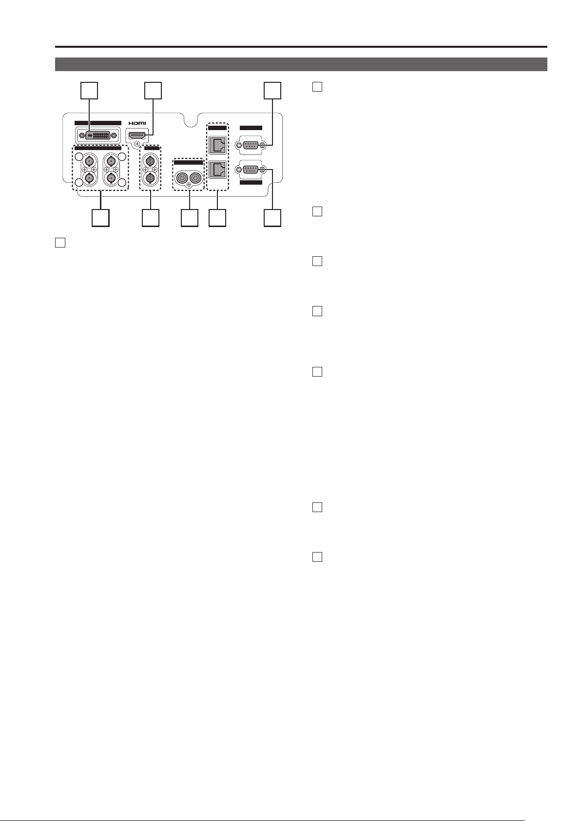
Rear panel
3 4 7
DVI-I
SDI VIDEO
1
2
1
IN
OUT
2
(3G)
3
IN
OUT IN
4
R L
AUDIO
RS-485 GPI
IN
OUT
RS-232C
2 6 81 5
1
SDI terminal
A SDI1 (3G/HD/SD) input terminal (BNC)
This is the SDI input terminal. (Compatible with 3G-SDI
and 3G/HD/SD automatic switching)
In 3D assist mode, input images for the left eye (L).
B SDI1 active through output terminal (BNC)
This terminal outputs SDI1 input as is.
C SDI2 (HD/SD) input terminal (BNC)
This is the SDI input terminal. (Compatible with HD/SD
automatic switching)
In 3D assist mode, input images for the right eye (R).
D SDI2 active through output terminal (BNC)
This terminal outputs SDI2 input as is.
• When this output is used to daisy-chain
tors, the quality of the original signal, cable length, the
number of connected devices and other factors all come
into play to deteriorate picture quality and introduce noise.
Daisy-chain:
*1
Refers to connecting the through-out signal from a
device to the input of a second, third or more devices
in a linear series, thus using a single signal in multiple
devices.
• Use a 5C-FB or equivalent cable to make connections to
an SDI terminal.
1
multiple moni-
*
2
VIDEO terminal (BNC)
*2*
3
IN : This is the VIDEO signal (composite signal) input
terminal.
OUT : This is the input signal through-out terminal.
Unless a cable is connected to the VIDEO OUT terminal,
*2
the VIDEO IN terminal is automatically terminated at
75 Ω. Connecting a cable releases this termination.
Since a connection to the through-out terminal releases the
*3
75 Ω termination of the unit, the level of the VIDEO signal
input to the unit may become too large depending on the
connected device.
3
DVI-I terminal
This is the DVI-signal input terminal.
• Use double shielded cable for making connections to a
DVI-I terminal.
4
HDMI terminal (Type A)
This is the HDMI input terminal.
• Use double-shielded cable for making connections to an
HDMI terminal.
5
AUDIO input terminal (pin jack)
This is the common audio input terminal for all video input
terminals.
• Use shielded cable for making connections to an AUDIO
input terminal.
6
RS-485 input/output terminal (RJ-45)
External control is possible by using an RS-485 signal.
• Use shielded cable for making connections to an RS-485
input/output terminal.
• Make sure that the cable is fully inserted in the terminal
and cannot easily be pulled out.
• A loop-through connection using the RS-485 input and
output terminals allows operation of multiple monitors (up
to 32 monitors).
• Connect a terminator (120 Ω) between the first and second pin of the RS-485 OUT terminal on the last monitor in
the chain.
7
GPI input terminal (D-SUB, 9 pins)
External control is possible by using a GPI signal.
• Use shielded cable for making connections to the GPI
input terminal.
8
RS-232C input terminal (D-SUB, 9 pins)
External control is possible by using an RS-232C signal
• Use shielded cable for making connections to an RS-232C
input terminal.
13
Page 14
15
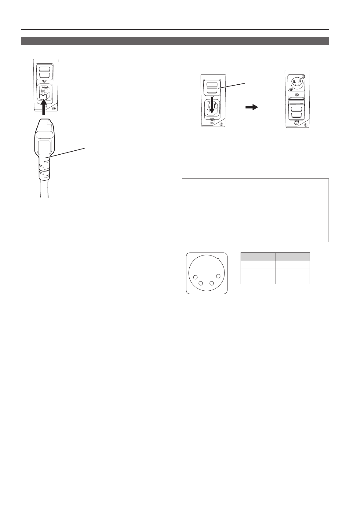
Power supply
Connecting the power cable
1.
Attach the power cable to the unit.
Power cable
2. Connect the power cable to the power outlet.
When using external DC power (12 V DC)
You can slide open the power cover to switch from AC input
to external DC input.
Power cover
<Note>
• If the power cover has come off or been removed, do not use
the monitor with the power supply connected to both AC input
and DC input terminals.
• Use a shielded DC cable that is not longer than 2 m. A cable
that is 2 m or longer may cause screen noise.
Before using an external DC power supply, be sure to check
that the rating of the external DC power supply suits the
power requirements of this monitor.
Check the pin arrangements of the DC output terminal of the
external DC power supply and those of the DC IN socket of
this monitor to ensure that a connection will maintain the correct polarity.
If +12 V is accidentally connected the GND terminal, fire or
injury could result.
1
External DC input
terminal
4
2 3
Pin number Signal
1 GND
2, 3 ―
4 +12 V
14
Page 15
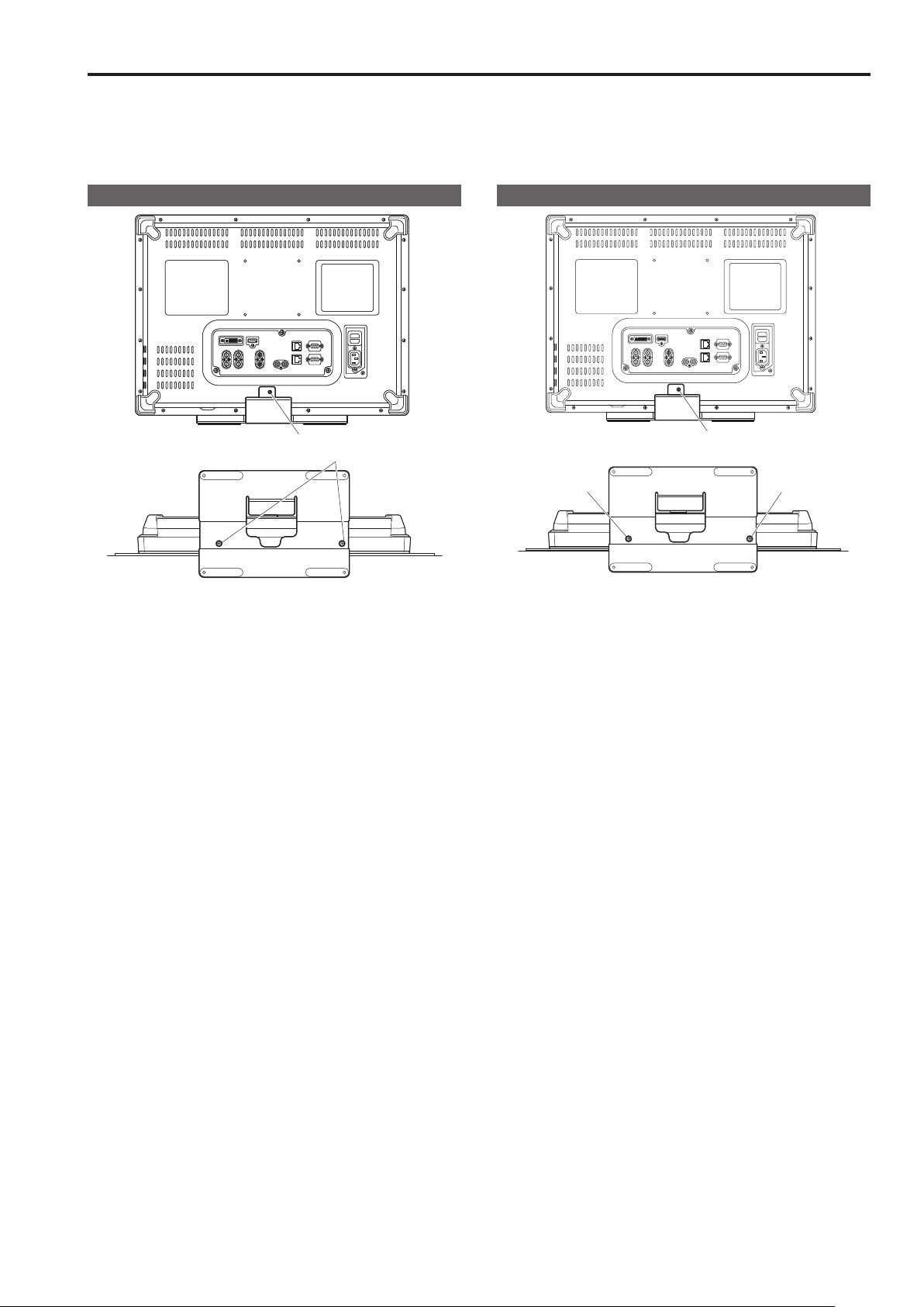
Detaching and Attaching the Stand
The stand is detachable.
• When detaching and attaching the stand, it is recommended that you place the monitor flat on the edge of a desk or table with a soft
cloth or similar material spread underneath.
• The stand is specifically designed for this monitor and cannot be used with other monitors. The stands supplied with the BT-LH1700W/
1710/1760 series cannot be used with this unit.
Detaching the stand
Stand screws
Unscrew the stand screws (three) using a Phillips screwdriver.
• After detaching, store the stand and the stand screws for the
stand in a location easily accessible when required.
Attaching the stand
③
②
①
1. Align the holes in the stand with those in the monitor.
2. Use a Phillips screwdriver to secure the stand to the
monitor with the stand screws (three).
• Install the stand screws in the (① to ③) order shown in the
figure.
15
Page 16
17
On-screen Display
The screen shows the operation status display, the main menu (MAIN MENU) / FUNCTION menu / INPUT SELECT menu displays,
picture adjusting (PICTURE) menu display, audio volume display, sharpness display, FUNCTION display, audio volume bar meter
display, time code (TC) display, closed caption (CC) display, IMD (in monitor display) display and other information.
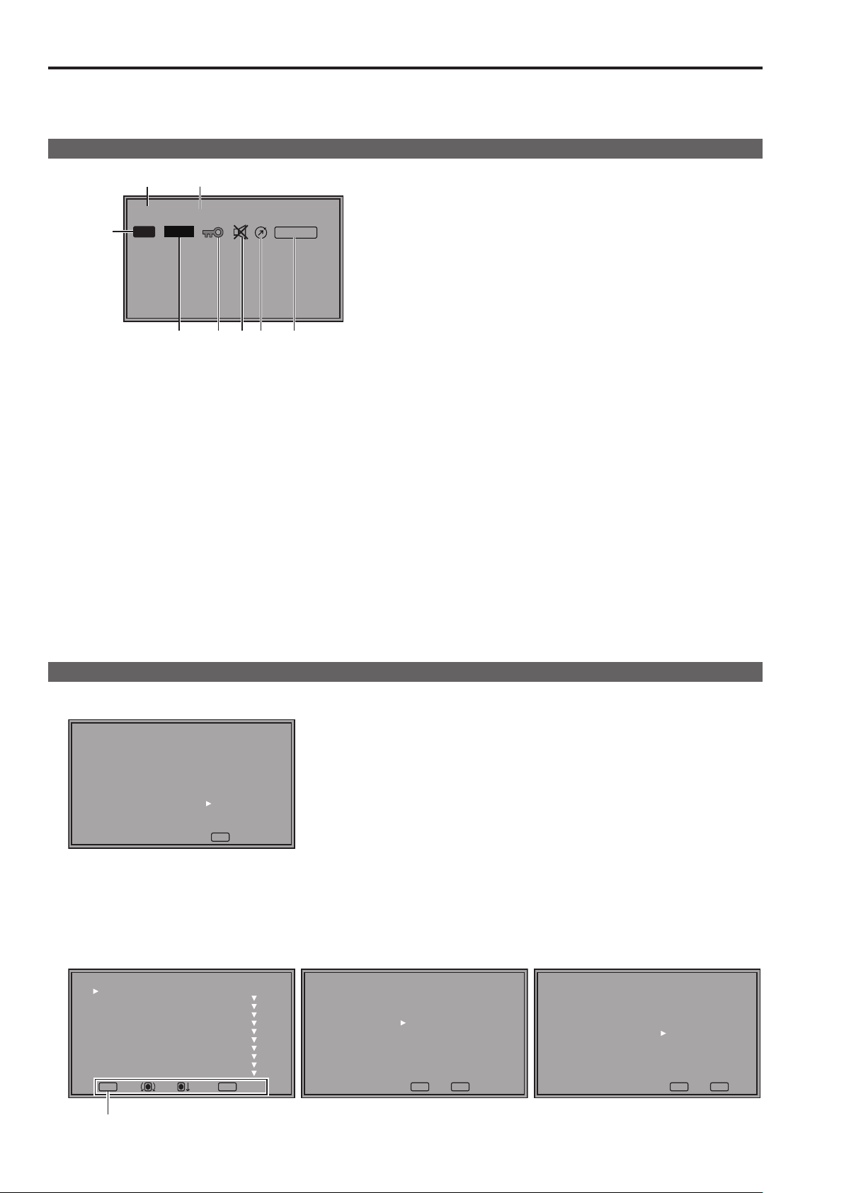
Operating status display
1
SDI1 1080/60i 3G:A
3
P-P
FILM
4
526 7 8
ANALOG
<Note>
• Use [STATUS DISPLAY] in the [SYSTEM CONFIG] menu to
set the display status.(→page 30)
• Icons meeting the 3 to 8 display requirements appear aligned
to the left.
• [UNSUPPORT SIGNAL] and [NO SIGNAL] may not be properly displayed.
• For details on the display of names and signal formats of
assist functions in 3D assist mode, refer to “3D Assist Mode”
(→page49).
In 3D assist mode, the various indications (4 to 8) can be
displayed as well.
1. The selected input line (→pages 12 and 20)
• Displays [VIDEO], [SDI1], [SDI2], [HDMI], [DVI-I] ([YPBPR]/
[RGB-COMP.]/[DVI-VIDEO]/[DVI-COMP.]) and [INT-SG].
2. Signal format
• [UNSUPPORT SIGNAL] appears if an unsupported signal
is input.
It may also indicate that the format selected in the [INPUT
SELECT] menu does not match the input signal.
• [NO SIGNAL] appears when no signal is input.
• The level of a 3G-SDI signal input is displayed to the right of the
signal format.
3. Various indications (PIXEL TO PIXEL mode)
• This indicates that the PIXEL TO PIXEL mode is engaged.
4. Various indications (FILM mode)
• This indicates that [GAMMA SELECT] in [VIDEO CONFIG]
is set to [FILM].
5. Various indications (Lock setting)
• This indicates that the front operations are locked.(→page 48)
6. Various indications (mute indication)
• Indicates that the speaker and headphones are muted.
(→page 21)
7. Various indications (indication of picture adjustment
change)
• Indicates that picture adjustments ([PEAKING]/[PHASE]/
[CHROMA]/[BRIGHT]/[CONTRAST]/[BACKLIGHT]) have
been changed from the values assigned using [SETUP
LOAD] or [POWER ON SETUP].(→page 21)
8. Various indications (ANALOG mode)
• Indicates that the operating mode has been set to analog
audio input using [INPUT SELECT] in the [AUDIO] menu.
Main menu (MAIN MENU)/FUNCTION menu/INPUT SELECT menu displays
1.
Press <MENU> when no menu is displayed.
• The [TOP MENU] appears.
[TOP MENU]
MAIN MENU
FUNCTION
INPUT SELECT
MENUEXIT
2. Turn the rotary knob <PICTURE> to select a menu ([MAIN MENU], [FUNCTION], [INPUT SELECT]) and press the rotary
knob <PICTURE>.
• For details on how to operate menus, refer to “How to Use the On Screen Menu” (→page20).
• In 3D assist and TWO WINDOW mode, the input is fixed to SDI1/SDI2 display and the [INPUT SELECT] menu cannot be selected.
[MAIN MENU] [FUNCTION] [INPUT SELECT]
[MAIN MENU]
2D/3D ASSIST
MARKER
VIDEO CONFIG
SYSTEM CONFIG
FUNCTION
GPI
INPUT SELECT
AUDIO
DISPLAY SETUP
CONTROL
HOURS METER
MENUEXIT
RETURN
2D
[FUNCTION]
F1:WFM/VECTOR
F2:TWO WINDOW
F3:FOCUS-IN-RED
F4:TIME CODE
F5:LEVEL METER
RETURNSEL. ENTER
WFM/VECTOR OFF
MENUEXIT
RETURN
RETURN
[INPUT SELECT]
VIDEO
SDI1
SDI2
HDMI
DVI-I
INT-SG
MENUEXIT
RETURN
RETURN
Displays instructions on <MENU> button operations.
16
Page 17
On-screen Display (continued)
3. To close a menu, press <MENU>.
• The menu display disappears after approx. 2 minutes of inaction. (The value shown before the display clears is confirmed.)
Picture adjusting (PICTURE) menu display
1. Press rotary knob <PICTURE> when no menu is dis-
[PICTURE]
SETTING[FACTORY]
PEAKING
PHASE
CHROMA
BRIGHT
CONTRAST
BACKLIGHT
F-IN-R
MENUEXIT
31
30
30
52
80
15
0
A
*
B
*
A: File names called by [SETUP LOAD] or [POWER ON
SETUP] appear on the screen to the right of [SETTING].
B: When picture adjustments ([PEAKING]/[PHASE]/[CHRO-
MA]/[BRIGHT]/[CONTRAST]/[BACKLIGHT]) have been
changed from the values assigned using [SETUP LOAD]
or [POWER ON SETUP], an asterisk (
of the menu name.
) appears to right
*
played.
• The [PICTURE] (picture adjusting) menu appears.
• For details on how to operate menus, refer to “How to Use
the On Screen Menu” (→page20).
2. To close a menu, press <MENU>.
• This display disappears after approx. 10 seconds of inaction. (The value shown before the display clears is confirmed.)
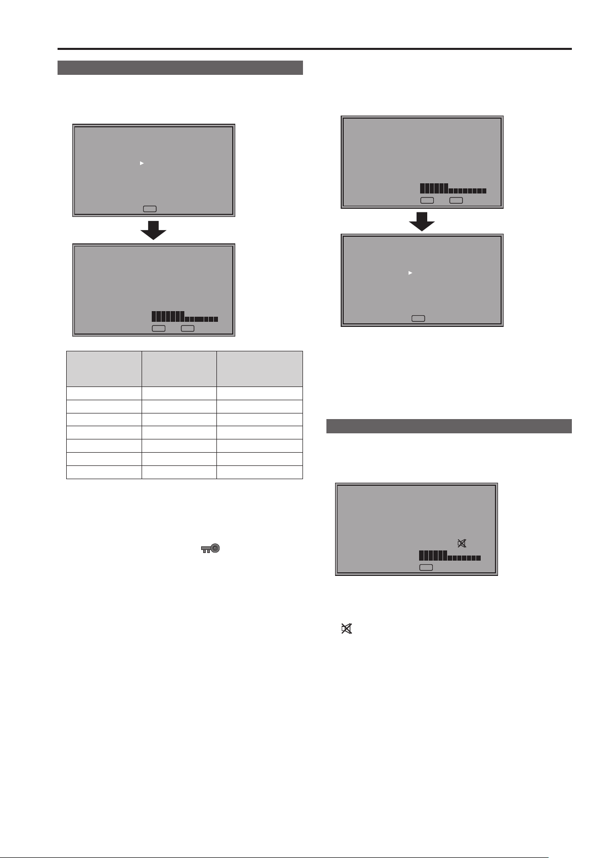
Audio volume display
Sharpness display
[VOLUME] 30
MENUEXIT
[SHARPNESS H] 14
RETURN
MENUEXIT
RETURN
1. Press <RETURN / VOLUME> when no menu is displayed.
• The audio volume bar meter appears.
• For details on how to use the audio volume, refer to“How to
Use the On Screen Menu” (→page20).
2. To close a menu, press <MENU> or the rotary knob
<PICTURE>.
• This display disappears after approx. 10 seconds of inaction. (The value shown before the display clears is confirmed.)
• Indicates the [SHARPNESS H] and [SHARPNESS V] setting
of the [VIDEO CONFIG] menu.
• When no operation is performed for approx. 2 minutes, the set
value is confirmed and the display disappears.
FUNCTION display
[FUNCTION]
F1:WFM/VECTOR
F2:TWO WINDOW
F3:FOCUS-IN-RED
F4:TIME CODE
F5:LEVEL METER
WFM/VECTOR OFF
MENUEXIT
RETURN
RETURN
• Use the [FUNCTION] menu to set up functions.
• When [FUNCTION DISPLAY] (→page 35) is set to [ON1] or
[ON2], press any of the <FUNCTION1> to <FUNCTION5>
buttons to display the status of functions assigned to the
FUNCTION buttons.
• When no operation is performed for approx. 2 seconds, the
A
set value is confirmed and the display disappears.
• "A" indicates operating status.(→page37 “Functions displayed
during FUNCTION button operation”)
Page 18
On-screen Display (continued)
19
Audio volume bar meter display
● Normal operating mode
Reference point
Channel display
11
33
55
77
SDI1 1080/60i
● In TWO WINDOW mode
11
33
55
77
0 dB point
Overrange
22
11
33
44
55
66
77
88
Peak hold
• A color bar meter indicates the audio level for SDI, HDMI and
AUDIO signals.
• The display method of the audio volume bar meter can be set
in the menu.(→page 45)
• In 3D assist mode, you can monitor the left (L) channel of
22
44
66
88
SDI1 audio.
• In TWO WINDOW mode, it will display SDI1 and SDI2 in
separate windows.
Display color
Green: Up to reference point (included)
Yellow: Reference point (not included) to 0 dB point (not in-
cluded)
Red: Overrange
22
44
66
88
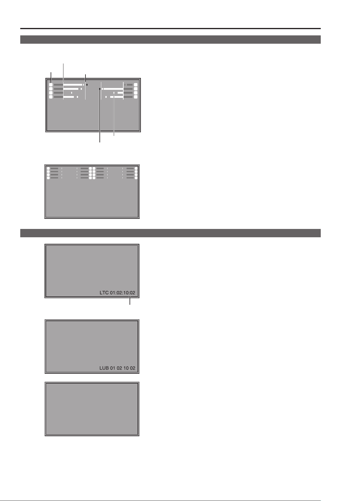
Time code (TC) display
( : ) NDF
( . ) DF
• Use the menu to display the time code for HD-SDI signal
input. It also allows you to switch between display modes:
([LTC], [VITC], [LUB], [VUB], [LTC+LUB], [VITC+VUB]).
(→page 46)
In LTC and VITC display mode
• Displays the time code in: hours: minutes: seconds: or frames.
• In drop-frame mode, a different delimiter is used between
seconds and frames.
<Note>
Read errors are displayed as “--:--:--:--”
In LUB and VUB display modes
• BG8, BG7, BG6, BG5, BG4, BG3, BG2, BG1 appear in the
stated order.
BG: binary group
• The (:) delimiter does not appear.
<Note>
Read errors are displayed as “-- -- -- --”
In LTC+LUB and VITC+VUB display modes
Each combination is displayed separately.
18
LTC 01:02:10:02
LUB
AB CD EF
01
Page 19
On-screen Display (continued)
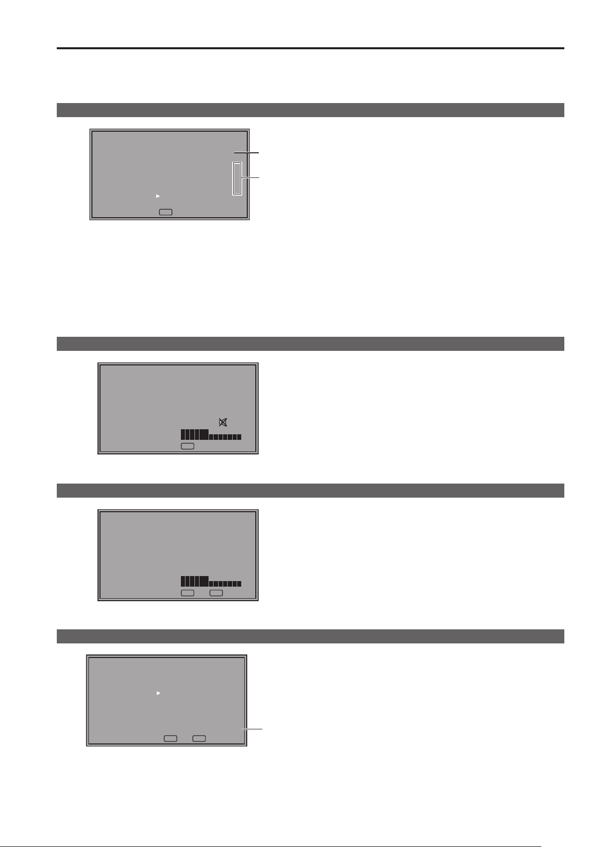
Closed caption (CC) display
Closed caption
display area
(When the specified window extends beyond the entire screen)
• This unit can display closed captions with an SDI or VIDEO
signal input.
• Closed captions comply with the following standards.
• Composite Standard EIA/CEA-608 (VBI), OP-42
• SD-SDI CC Standard EIA/CEA-608 (ANC/VBI), OP-42
• HD-SDI CC Standard EIA/CEA-608 (708),
EIA/CEA-708, OP-47
• The EIA/CEA-708 Standard allows simultaneous display of
closed captions at a specified location on up to eight windows.
• Closed captions are displayed on an area inside the screen
that is smaller than the entire screen.
(Refer to the following notes.)
• The display settings can be configured in the menus. The
menu also allow you to select closed caption type, display
channel (EIA/CEA-608) and display service (EIA/CEA-708).
(→page 46)
<Note>
• The specified window position is displayed at a position in the
display area according to the closed caption information.
• The window may extend beyond the display area depending
on the position and size of the specified window. Such a window will be displayed but a window that extends beyond the
entire screen will be repositioned inside the screen area.
IMD (in monitor display) display
● Normal operating mode
CAM1
Tally 1 Tally 2Text
● In TWO WINDOW mode
CAM1 CAM2
• This monitor supports the TSL UMD PROTOCOL (Ver. 3.1
and Ver. 4.0) and allows you to display text and the tally indication on the monitor using the RS-485 interface.
• For information on how to set IMD and communications, refer
to pages 47, 48, 63.
• In TWO WINDOW mode, it will display SDI1 and SDI2 in
separate in monitor display (IMD) windows.
19
Page 20

21
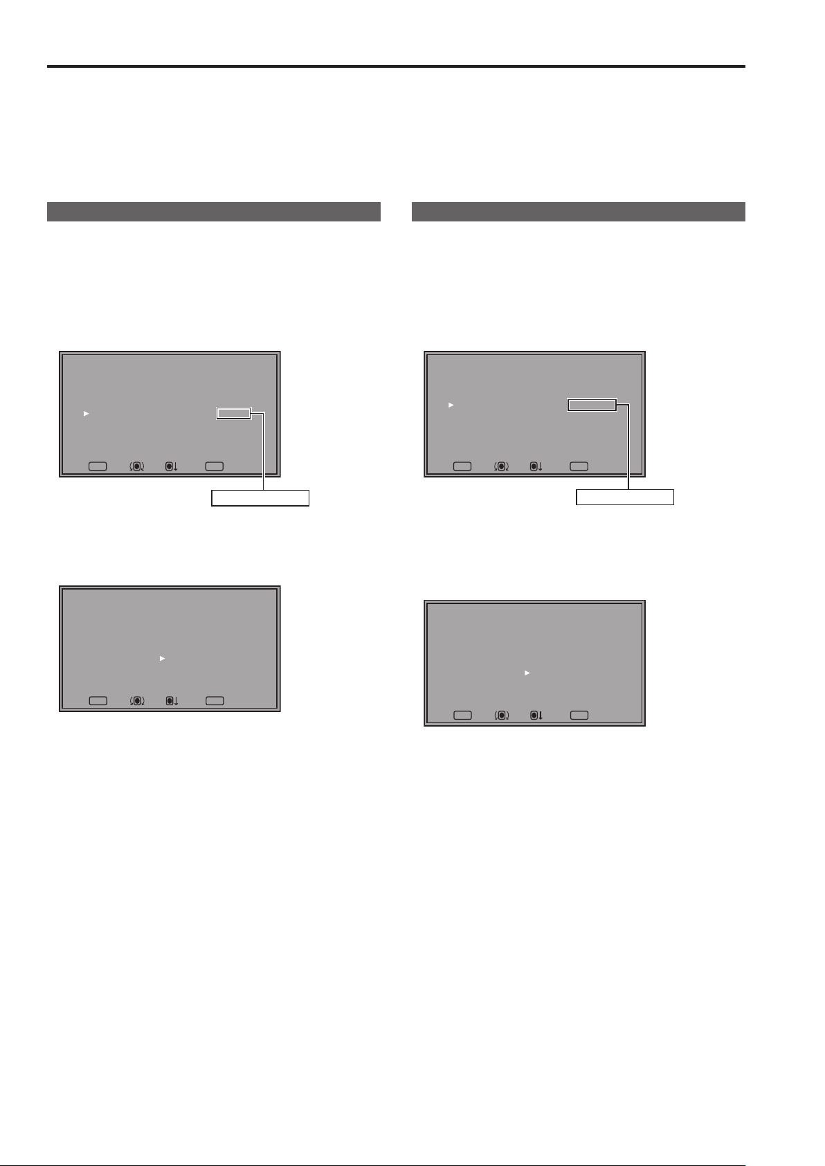
How to Use the On Screen Menu
Main menu (MAIN MENU)
• For details on how to open the main menu, refer to “Main
menu (MAIN MENU)/FUNCTION menu/INPUT SELECT menu
displays” (→page16).
1. Turn the rotary knob <PICTURE> to select a menu item
and press the rotary knob <PICTURE>.
[MAIN MENU]
2D/3D ASSIST
MARKER
VIDEO CONFIG
SYSTEM CONFIG
FUNCTION
GPI
INPUT SELECT
AUDIO
DISPLAY SETUP
CONTROL
HOURS METER
MENUEXIT
RETURN
2D
RETURNSEL. ENTER
2. Turn the rotary knob <PICTURE> to select a submenu
item and press the rotary knob <PICTURE>.
• The settings in the submenu change to green.
[MARKER]
MARKER
16:9
4:3
BACK
CENTER
CROSS
COLOR
GPI MARKER1
GPI MARKER2
CROSS HATCH
SIZE
MENUEXIT
OFF
4:3
OFF
NORMAL
OFF
OFF
WHITE
95%(16:9)
95%(16:9)
OFF
LARGE
RETURN
RETURNSEL. ENTER
FUNCTION menu
• For details on how to open the [FUNCTION] menu, refer to
“Main menu (MAIN MENU)/FUNCTION menu/INPUT SELECT
menu displays” (→page16).
1. Turn the rotary knob <PICTURE> to select a function
item.
• Selected function item and set value appear in green.
[FUNCTION]
F1:WFM/VECTOR
F2:TWO WINDOW
F3:FOCUS-IN-RED
F4:TIME CODE
F5:LEVEL METER
WFM/VECTOR OFF
MENUEXIT
RETURN
RETURN
A
2. Press the rotary knob <PICTURE>.
• Each press of the rotary knob <PICTURE> changes the set
value and enables function operation.
[FUNCTION]
F1:WFM/VECTOR
F2:TWO WINDOW
F3:FOCUS-IN-RED
F4:TIME CODE
F5:LEVEL METER
WFM/VECTOR OFF
MENUEXIT
RETURN
RETURN
A
3. To return to the [TOP MENU], press <RETURN/VOLUME>.
3. Turn the rotary knob <PICTURE> to select a set value
and press the rotary knob <PICTURE>.
• To cancel, press <RETURN/VOLUME> before pressing the
rotary knob <PICTURE>.
[MARKER]
MARKER
16:9
4:3
BACK
CENTER
CROSS
COLOR
GPI MARKER1
GPI MARKER2
CROSS HATCH
SIZE
MENUEXIT
95%(16:9)
95%(16:9)
4:3
OFF
NORMAL
OFF
OFF
WHITE
OFF
LARGE
RETURN
RETURNSEL. ENTER
ON
4. To return to the previous screen, press <RETURN/VOL-
UME>.
INPUT SELECT menu
• For details on how to open the [INPUT SELECT] menu, refer
to “Main menu (MAIN MENU)/FUNCTION menu/INPUT SELECT menu displays” (→page16).
1. Turn the rotary knob <PICTURE> to select an input signal
terminal or [INT-SG] and press the rotary knob <PICTURE>.
• To cancel, press<RETURN/VOLUME> before pressing the
rotary knob <PICTURE>.
[INPUT SELECT]
VIDEO
SDI1
SDI2
HDMI
DVI-I
INT-SG
MENUEXIT
RETURN
RETURN
VIDEO : Video input
SDI1 : Serial digital interface input
SDI2 : Serial digital interface input
HDMI : HDMI input
1
DVI-I
: DVI-I input
*
INT-SG
2
: Internal chart for adjustment ([Color Bar +
*
Grayscale]) (→page 77)
The name of the DVI-I input terminal is fixed at [DVI-I].
*1
[INPUT NAME SETUP] in the [SYSTEM CONFIG] menu
cannot be used to change names.
It is not possible to switch to [INT-SG] when two screens are
*2
displayed with the SUB WINDOW function(→page 38).
2. To return to the [TOP MENU], press <RETURN/VOLUME>.
20
Page 21
How to Use the On Screen Menu (continued)
Picture adjusting (PICTURE) menu
1.
Turn the rotary knob <PICTURE> to select a menu item
and press the rotary knob <PICTURE>.
• The menu closes and the set values of the selected menu
items appear.
[PICTURE]
SETTING[FACTORY]
PEAKING
PHASE
CHROMA
BRIGHT
CONTRAST
BACKLIGHT
F-IN-R
MENUEXIT
[PHASE] 30
RETURN
MENUEXIT
Name Function
PEAKING PEAKING 0 to 30 (0)
PHASE PHASE 0 to 60 (30)
CHROMA CHROMA 0 to 60 (30)
BRIGHT BRIGHT 0 to 60 (30)
CONTRAST CONTRAST 0 to 60 (50)
BACKLIGHT BACKLIGHT 0 to 100 (80)
F-IN-R FOCUS-IN-RED 1 to 30 (15)
The text color of set values that are factory defaults is green
and other values are white.
Settings are loaded when the monitor is turned on. However,
operations and changes cannot be made in the following
conditions.
• When the control lock is on, the
set values cannot be changed. (→page 48)
• When the [MONO] (→page 28) is set to [ON], [PHASE] and
[CHROMA] operations are disabled.
• [F-IN-R] is enabled during operation of the FOCUS-IN-
RED function.
• [BRIGHT] operation is disabled during [HV DELAY]
(→page 34) operation (when it is in any other setting than
OFF).
• [CONTRAST] and [BACKLIGHT] operations are disabled
in [BLACK MODE] (→page 34).
0
30
30
30
50
80
15
RETURN
Adjustable range
( ): denotes factory
mark appears and
defaults.
2. Turn the rotary knob <PICTURE> to select a set value
and press the rotary knob <PICTURE>.
• The set value is confirmed and the menu reappears.
• To cancel, press <RETURN/VOLUME> before pressing the
rotary knob <PICTURE>.
[PHASE] 20
RETURN
MENUEXIT
[PICTURE]
SETTING[FACTORY]
PEAKING
PHASE
CHROMA
BRIGHT
CONTRAST
BACKLIGHT
F-IN-R
MENUEXIT
RETURN
20
30
30
50
80
15
0
*
• When picture adjustments ([PEAKING]/[PHASE]/[CHROMA]/[BRIGHT]/[CONTRAST]/[BACKLIGHT]) have been
changed from the values assigned using [SETUP LOAD] or
[POWER ON SETUP], an asterisk (
menu name.
) appears to right of the
*
Audio volume
• For details on how to use the audio volume, refer to“Audio
volume display” (→page17).
1. Turn the rotary knob <PICTURE> to select a set value.
[VOLUME] 30
MENUEXIT
• Set values are confirmed when they are changed.
• Changing the audio volume when audio output is muted
(“AUDIO MUTE” (→page 35)) immediately cancels [AUDIO
MUTE].
•
is displayed when audio output of the monitor is muted.
• Audio volume is always available and is not affected by the
[CONTROL] menu (→page 48).
• The adjustment range is 0 to 60 (the factory default is 0)
Page 22
23
User Data
This monitor can save up to five combinations of set values for MAIN MENU and screen adjustments made in the [PICTURE] (picture
adjusting) menu as user data that can be recalled.
You can also return set values and adjustments to their factory defaults.
User data include the following settings.
• Menu settings except [SETUP LOAD], [SETUP SAVE] and [REMOTE] in [CONTROL] (including button function settings on the
monitor front panel)
• Screen adjustments made with the rotary knob <PICTURE>
Saving user data
1.
Press <MENU> to display the main menu.
2. Turn the rotary knob <PICTURE> to select the [SYSTEM
CONFIG] menu and press the rotary knob <PICTURE>.
3. Turn the rotary knob <PICTURE> to select the [SETUP
SAVE] submenu and press the rotary knob <PICTURE>.
The set values in the submenu change to green.
[SYSTEM CONFIG]
SUB WINDOW
MENU POSITION
STATUS DISPLAY
INPUT NAME SETUP
SETUP LOAD
SETUP SAVE
POWER ON SETUP
COLOR SPACE
POWER DOWN
POWER SAVE MODE
CALIBRATION
MENUEXIT
FULL
CENTER
3SEC OFF
FACTORY
USER1
LAST
EBU
OFF
OFF
RETURN
RETURNSEL. ENTER
Changes to green
4. Turn the rotary knob <PICTURE> to select settings to
save from the [USER1] to [USER5] and press the rotary
knob <PICTURE>.
The following screen appears.
[SETUP SAVE]
USER1
YES
NO
Loading user data
1.
Press <MENU> to display the main menu.
2. Turn the rotary knob <PICTURE> to select the [SYSTEM
CONFIG] menu and press the rotary knob <PICTURE>.
3. Turn the rotary knob <PICTURE> to select the [SETUP
LOAD] submenu and press the rotary knob <PICTURE>.
The set values in the submenu change to green.
[SYSTEM CONFIG]
SUB WINDOW
MENU POSITION
STATUS DISPLAY
INPUT NAME SETUP
SETUP LOAD
SETUP SAVE
POWER ON SETUP
COLOR SPACE
POWER DOWN
POWER SAVE MODE
CALIBRATION
MENUEXIT
FULL
CENTER
3SEC OFF
FACTORY
USER1
LAST
EBU
OFF
OFF
RETURN
RETURNSEL. ENTER
Changes to green
4. Turn the rotary knob <PICTURE> to select settings to call
from the [USER1] to [USER5] and press the rotary knob
<PICTURE>.
The following screen appears.
• To return to the factory defaults, select [FACTORY].
[SETUP LOAD]
USER1
YES
NO
MENUEXIT
RETURN
RETURNSEL. ENTER
5. Select [YES] and press the rotary knob <PICTURE>.
This saves the user data.
6. To return to the previous screen, press <RETURN/VOL-
UME>.
MENUEXIT
RETURN
RETURNSEL. ENTER
5. Select [YES] and press the rotary knob <PICTURE>.
This loads the user data.
6. To return to the previous screen, press <RETURN/VOL-
UME>.
22
Page 23
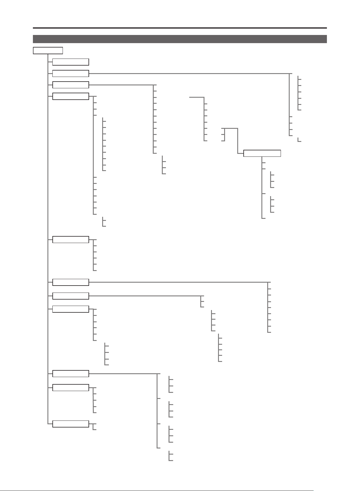
Main Menu
CROSS HATCH
Menu configuration
MAIN MENU
2D/3D ASSIST
MARKER
VIDEO CONFIG
SYSTEM CONFIG
FUNCTION
SUB WINDOW
MENU POSITION
STATUS DISPLAY
INPUT NAME SETUP
VIDEO
SDI1
SDI2
HDMI
BPR
YP
RGB-COMP.
DVI-VIDEO
DVI-COMP.
INT-SG
SETUP LOAD
SETUP SAVE
POWER ON SETUP
COLOR SPACE
POWER DOWN
POWER SAVE MODE
CALIBRATION
AUTO CALIBRATION
RESET
FUNCTION1
FUNCTION2
FUNCTION3
FUNCTION4
FUNCTION5
FUNCTION DISPLAY
GAMMA SELECT
FILM GAMMA
COLOR TEMP.
SHARPNESS MODE
SHARPNESS H
SHARPNESS V
I-P MODE
MONO
ANAMO
SD ASPECT
SCAN
ZEBRA INT.MIN.
INT. MAX.
EXT. MIN.
EXT. MAX.
USER0 to 63
D93
D65
D56
VAR1
VAR2
VAR3
WHITE BALANCE
COLOR TEMP.
GAIN
RED
GREEN
BLUE
BIAS
RED
GREEN
BLUE
RESET
MARKER
16:9
4:3
BACK
CENTER
CROSS
COLOR
GPI MARKER1
GPI MARKER2
MARKER TYPE
SIZE
GPI
INPUT SELECT
AUDIO
DISPLAY SETUP
CONTROL
HOURS METER
INPUT SELECT
GROUP SELECT
SELECT L
SELECT R
SPEAKER OUT
LEVEL METER
CH SELECT
POINT LINE
CH INFO.
HEAD ROOM
CONTROL
LOCAL ENABLE
PROTOCOL VER.
RS-485 ID SETUP
RS-485 STX&ETX
OPERATION
LCD
VIDEO
NTSC SETUP
DVI-I
DIGITAL
ANALOG
COMPONENT LEVEL
RGB-COMP.
H POSITION
V POSITION
PHASE
CLOCK
RESET
WFM/VECTOR
POSITION
VECTOR MODE
VECTOR SCALE
TIME CODE
POSITION
FONT SIZE
MODE SELECT
CLOSED CAPTION
CC TYPE
CAPTION CHANNEL
CAPTION SERVICE
IN MONITOR DISPLAY
POSITION
CHAR. COLOR
GPI CONTROL
GPI1
GPI2
GPI3
GPI4
GPI5
GPI6
GPI7
GPI8
23
Page 24
Main Menu (continued)
25
2D/3D ASSIST
Setting Description
2D
3D ASSIST
MARKER
Submenu Setting Description
MARKER
16:9
4:3
*2*
BACK
*2*
3
4
2
*
OFF
ON
OFF
4:3
13:9
14:9
CNSCO 2.39
CNSCO 2.35
2:1
VISTA
95%
93%
90%
88%
80%
USER 85%
VAR. H. 85% V. 85%
OFF
95%
93%
90%
88%
80%
USER 85%
VAR. H. 85% V. 85%
NORMAL
HALF
BLACK
Switches between 2D mode and 3D assist mode.
[2D] Operates in 2D mode.
[3D ASSIST] Operates in 3D assist mode.
When you switch to [3D ASSIST], the input line selection will be force switched to
SDI1 or SDI2.
1
*
Selects whether to enable or disable the marker setting.
Selects/displays various markers in 16:9 aspect ratio.
[OFF] No marker display
[4:3] 4:3 marker
[13:9] 13:9 marker
[14:9] 14:9 marker
[CNSCO 2.39] 2.39:1 marker
[CNSCO 2.35] 2.35:1 marker
[2:1] 2:1 marker
[VISTA] VISTA marker
[95%] 95 % area marker
[93%] 93.1 % area marker (TYPE1)
93 % area marker (TYPE2)
[90%] 90 % area marker
[88%] 89.5 % area marker (TYPE1)
88 % area marker (TYPE2)
[80%] 80 % area marker
[USER] An area marker that is adjustable in 1% increments within a range
of 80 to 100%. However, when the [MARKER TYPE] is [TYPE1],
88% and 93% indicate area markers whose height area 89.5% and
93.1%, respectively.
(The factory default is 85 %.)
[VAR.] This area marker can be varied in 1% increments in the range
between 80 to 100% separately for vertical and horizontal.
(The factory default is 85% for both vertical and horizontal)
Selects/displays the marker type for when the angle of view of the displayed
image is 4:3.
[OFF] No marker display
[95%] 95 % area marker
[93%] 93 % area marker
[90%] 90 % area marker
[88%] 89 % area marker (TYPE1)
88 % area marker (TYPE2)
[80%] 80 % area marker
[USER] An area marker that is adjustable in 1% increments within a range
of 80 to 100%. However, when the [MARKER TYPE] is [TYPE1], 88
% indicates an area marker whose height is 89%.
(The factory default is 85 %.)
[VAR.] This area marker can be varied in 1% increments in the range
between 80 to 100% separately for vertical and horizontal.
(The factory default is 85% for both vertical and horizontal)
Selects the background brightness around the marker.
[NORMAL] Normal background
[HALF] 50% signal level
[BLACK] 0 % signal level (black)
Underlined values indicate factory defaults.
Underlined values indicate factory defaults.
This setting is turned [ON] when receiving marker control signals in REMOTE operation. (GPI if set, has priority.)
*1
These settings are disabled when the GPI (→page 60) function is used to control the marker setting.
*2
These settings are enabled only for HD and SD signal input when [SD ASPECT] is set to [16:9] aspect ratio mode. (→ 28 page “SD
*3
ASPECT”)
These settings are enabled only for SD signal input when [SD ASPECT] is set to [4:3] aspect ratio mode. (→ 28 page “SD ASPECT”)
*4
24
Page 25

Main Menu (continued)
Submenu Setting Description
CENTER
CROSS
COLOR
GPI MARKER1
GPI MARKER2
2
*
OFF
ON
OFF
(H. xxxx V. yyyy)
WHITE
BLACK
RED
GREEN
BLUE
5
4:3
*
13:9
14:9
CNSCO 2.39
CNSCO 2.35
2:1
VISTA
95% (16:9)
93% (16:9)
90% (16:9)
88% (16:9)
80% (16:9)
5
*
USER (16:9)
VAR. (16:9)
95% (4:3)
93% (4:3)
90% (4:3)
88% (4:3)
80% (4:3)
USER (4:3)
VAR. (4:3)
Displays the center marker.
[OFF] No marker display
[ON] Turns the display on
Displays the cross marker.
[OFF] No marker display
[(H. xxxx V. yyyy)] Displays the marker
Horizontal (H: 20 to 1899), vertical (V: 20 to 1059) can
be displayed for any location. When a set value [(H. xxxx
V. yyyy)] has been confirmed, press the rotary knob
<PICTURE> again to set horizontal and vertical
positions.
(The factory default is set to H: 480 V: 270.)
Selects a marker color.
[WHITE] white
[BLACK] black
[RED] red
[GREEN] green
[BLUE] blue
GPI MARKER 1 : Selects the marker displayed by the GPI terminal
[MARKER1 ON/OFF] (→page 60) operation.
GPI MARKER 2 : Selects the marker displayed by the GPI terminal
[MARKER2 ON/OFF] (→page 60) operation.
[4:3] 4:3 marker
[13:9] 13:9 marker
[14:9] 14:9 marker
[CNSCO 2.39] 2.39:1 marker
[CNSCO 2.35] 2.35:1 marker
[2:1] 2:1 marker
[VISTA] VISTA marker
[95% (16:9)] 95 % area marker for 16:9 aspect ratio
[93% (16:9)] 93 % area marker for 16:9 aspect ratio
[90% (16:9)] 90 % area marker for 16:9 aspect ratio
[88% (16:9)] 88 % area marker for 16:9 aspect ratio
[80% (16:9)] 80 % area marker for 16:9 aspect ratio
[USER (16:9)] User set area marker for 16:9 aspect ratio
[VAR. (16:9)] VAR. set area marker for 16:9 aspect ratio
[95% (4:3)] 95 % area marker for 4:3 aspect ratio
[93% (4:3)] 93 % area marker for 4:3 aspect ratio
[90% (4:3)] 90 % area marker for 4:3 aspect ratio
[88% (4:3)] 88 % area marker for 4:3 aspect ratio
[80% (4:3)] 80 % area marker for 4:3 aspect ratio
[USER (4:3)] User set area marker for 4:3 aspect ratio
[VAR. (4:3)] VAR. set area marker for 4:3 aspect ratio
6
*
6
*
7
MARKER TYPE
CROSS HATCH
SIZE
These settings are disabled when the GPI (→page 60) function is used to control the marker setting.
*2
Remote control via RS-232C or RS-485 ends in error (error response: ER001) when [GPI MARKER1] or [GPI MARKER2] is se-
*5
lected with the GPI function.
Since video is displayed at 100%, the marker will not be visible if set to [100%].
*6
Display size for SD signals differ.
*7
TYPE1: The effective horizontal area meets the SMPTE ST125 for NTSC and ITU-R BT.601-5 for PAL.
TYPE2: The effective horizontal area meets the EIA-RS170A for NTSC and ITU-R BT.470-4 for PAL.
<Note>
• Markers other than the CROSS HATCH marker are not available during 2-screen display, PIXEL TO PIXEL mode, and 3D assist
mode.
TYPE1
*
TYPE2
OFF
LOW
HIGH
SMALL
LARGE
Selects conventional monitor or camera recorder marker size.
[TYPE1] Conventional monitor marker size
[TYPE2] Marker size compliant with camera recorder (Panasonic camera)
Turns the cross hatch grid on and off and sets its density.
[OFF] No cross hatch grid display
[LOW] Displays a dim cross hatch grid
[HIGH] Displays a bright cross hatch grid
Selects the cross hatch grid size.
[SMALL] 60 dots and 60 lines
[LARGE] 120 dots and 120 lines
25
Page 26

Main Menu (continued)
27
MARKER types
16:9 marker
(Displayed for HD input and SD input in 16:9 ratio mode.)
The marker is only displayed as a vertical bar. In addition, the
section becomes the “MARKER BACK” item.
4:3 marker 13:9 marker
14:9 marker
VISTA marker, 2:1 marker, CNSCO marker
A horizontal dotted line is displayed as the marker.
VISTA marker 2:1 marker
4:3 marker
(Displayed for SD input in 4:3 aspect ratio mode)
This marker is displayed as a dotted line.
95 % area marker 93 % area marker
90 % area marker 88 % area marker
80 % area marker
(Displayed for HD input and SD input in 16:9 ratio mode.)
This marker is displayed as a dotted line.
CNSCO marker (2.35/2.39)
The vertical dotted lines are also displayed as the marker
when [UNDER] is selected under [SCAN] in the [VIDEO
CONFIG] menu.
VISTA marker 2:1 marker
CNSCO marker (2.35/2.39)
Area marker
This marker is displayed as a dotted line.
TYPE1 Vertical 93.1%
Horizontal 93%
TYPE2 Vertical/Horizontal 93%
95 % area marker 93 % area marker
TYPE1 Vertical 89.5 %
Horizontal 88 %
TYPE2 Vertical/Horizontal 88 %
90 % area marker 88 % area marker
95 % area marker 93 % area marker
TYPE1 Vertical 89 % Horizontal 88 %
TYPE2 Vertical/Horizontal 88 %
90 % area marker 88 % area marker
80 %
Area marker
100 %
Area marker
80 % area marker
USER Area marker
VAR Area marker
1
*
2
*
You can display the 4:3 marker and the 16:9 marker
simultaneously.
Simultaneous display example
The area becomes the “MARKER BACK”.
It controls the background of the marker selected with a 16:9
ratio.
4:3 marker
16:9 marker
16:9 marker: 95 % area marker
4:3 marker: 80 % area marker
Center marker
Center marker
This marker is displayed at the center
of the screen.
80 % area marker
80 %
Area marker
100 %
Area marker
USER Area marker
VAR Area marker
1
*
2
*
Cross marker
Cross marker
Use the rotary knob <PICTURE> to
move. (The cross marker is half the
length of the center marker and twice
the width)
Use the rotary knob <PICTURE> to set 80 to 100% in 1% increments.
*1
Use the rotary knob <PICTURE> to set 80 to 100% in 1% increments separately for vertical and horizontal.
*2
26
Page 27

Main Menu (continued)
(Gumma curve image)
Brightness
VIDEO CONFIG
Submenu Setting Description
GAMMA SELECT
FILM GAMMA
*1*
2
STANDARD
FILM
STDIO/PST
CINEMA
VARICAM
OTHER
The underlined values are factory defaults.
Selects gamma curve.
[STANDARD] Standard mode (power of 2.2)
[FILM] Film mode
[STDIO/PST] Color emphasis mode (power of 2.35)
[CINEMA] CINEMA mode (power of 2.6)
• When [FILM] is selected, the
Selects type of FILM gamma mode.
[VARICAM] For VARICAM use [OTHER] For other cameras
OTHER
Video Gamma
mark is displayed for the operating status.
VARICAM
COLOR TEMP.
SHARPNESS MODE
SHARPNESS H
SHARPNESS V
When the SUB WINDOW function is used, changes are not reflected to the still image in the main window.
*1
This menu is grayed out when the same item is assigned to GPI and [GPI CONTROL] is set to [ENABLE].
*2
To select [USER 0 to 63]
*3
A Press the rotary knob <PICTURE>. ([USER] changes to blue)
B Use the rotary knob <PICTURE> to select 0 to 63 and press the rotary knob <PICTURE>.
Selecting [VAR1], [VAR2] or [VAR3] engages the WB adjustment mode.(→page 29)
*4
The following sharpness values
*5
A VIDEO system input (VIDEO) (the factory defaults are SHARPNESS MODE: LOW and SHARPNESS H/SHARPNESS V: 0)
B HD inputs other than A above (the factory defaults are SHARPNESS MODE: HIGH and SHARPNESS H/SHARPNESS V: 0).
C SD inputs other than A above (the factory defaults are SHARPNESS MODE: LOW and SHARPNESS H/SHARPNESS V: 0).
are available and the settings for the selected input signal is displayed. During selection, adjustment status is displayed below the
[PICTURE] (picture adjusting) menu.
When HD signals are input via SDI1 and SD signals via SDI2 or SD signals via SDI1 and HD signals via SDI2 in TWO WINDOW or
*6
PICTURE ASSIST function operation, changes in the sharpness setting from the menu affect only the left screen.
Input Level
3
USER 0 to 63
D93
D65
D56
VAR1
VAR2
VAR3
5
6
HIGH
*
*
LOW
5
6
*
*
5
*
*
0 to 30 Sets horizontal outline correction. The item display moves to the lower part of the
6
0 to 30 Sets vertical outline correction. The item display moves to the lower part of the
Selects color temperature.
*
[USER 0 to 63] Adjustable settings 0 to 63
(equivalent to a color temperature range of 3,000 K to 9,300 K)
[D93] Equivalent to a color temperature of 9,300 K
[D65] Equivalent to a color temperature of 6,500K
[D56] Equivalent to a color temperature of 5,600 K
[VAR1] WB (White Balance) adjustment mode
[VAR2] WB (White Balance) adjustment mode
[VAR3] WB (White Balance) adjustment mode
Selects the width of outline correction edge.
[HIGH] Narrow edge
[LOW] Wide edge
screen during adjustment.
screen during adjustment.
4
*
4
*
4
*
(Continued on next page)
27
Page 28

Main Menu (continued)
29
Submenu Setting Description
*
*2*
7
*
2
8
*
2
*
8
9
*
*
*
I-P MODE
MONO
ANAMO
SD ASPECT
SCAN
ZEBRA INT. MIN.
INT. MAX.
EXT. MIN.
EXT. MAX.
This menu is grayed out when the same item is assigned to GPI and [GPI CONTROL] is set to [ENABLE].
*2
To use the SUB WINDOW (→page 38) function,
*7
A Change settings after exiting the SUB WINDOW function.
B It is recommended to use [MODE2] for handling fast video.
[SCAN] changes are not reflected in Anamo size display.
*8
The ZEBRA function must be set according to the following conditions.
*9
[INT. MIN.] < [INT. MAX.]
[EXT. MIN.] < [EXT. MAX.]
[EXT. MIN.] ≦ [INT. MIN.]
[INT. MAX.] ≦ [EXT. MAX.]
9
9
9
*
MODE1
MODE2
OFF
ON
OFF
ON
4:3
16:9
NORMAL
UNDER
-7% to 108%
(Factory default
setting: 70%)
-6% to 109%
(Factory default
setting: 85%)
-7% to 108%
(Factory default
setting: 5%)
-6% to 109%
(Factory default
setting: 100%)
Selects IP conversion mode. (see “IP mode” (→This page).)
[MODE1] Intra-frame interpolation
[MODE2] Intra-field interpolation
Switches between color and monochrome (MONO).
[OFF] Color
[ON] Monochrome
• When [ON], the [CHROMA] setting of the [PICTURE] (picture adjusting) menu is
fixed at 0.
With an Anamo lens and HD-SDI input, the picture is resized to Anamo
magnification. (the vertically enlarged signal can be vertically compressed and
corrected for display).
Sets the aspect ratio for SD signal input.
[4:3] 4:3 display
[16:9] 16:9 display
Sets under-scan and normal display.
[NORMAL] Normal display
[UNDER] Under-scan
Sets the range of the ZEBRA function.
Displays the minimum value of the INT. range as a percentage of the video signal.
Sets the range of the ZEBRA function.
Displays the maximum value of the INT. range as a percentage of the video signal.
Sets the range of the ZEBRA function.
Displays the minimum value of the EXT. range as a percentage of the video signal.
Sets the range of the ZEBRA function.
Displays the maximum value of the EXT. range as a percentage of the video signal.
IP mode
[MODE1] performs IP conversion using intra-frame interpolation.
This monitor suppresses the delay to within 1 field.
The factory default is [MODE1].
[MODE2] performs IP conversion using intra-field interpolation.
Since interpolation is performed inside each field, this mode is suitable for checking interlace status.
28
Page 29

Main Menu (continued)
WB (WHITE BALANCE) adjustment mode
Select [VAR1] to [VAR3] for [COLOR TEMP.] in the [VIDEO CONFIG] menu to make WHITE BALANCE VAR1
VAR3 adjustments.
Underlined values indicate factory defaults.
Submenu Setting Description
COLOR TEMP.
*
USER 0 to 63
D93
D65
D56
Selects the color temperature that will become the basis for adjustment.
[USER 0 to 63] Adjustable settings 0 to 63
(equivalent to a color temperature range of 3,000 K to 9,300 K)
[D93] Equivalent to a color temperature of 9,300 K
10
[D65] Equivalent to a color temperature of 6,500K
[D56] Equivalent to a color temperature of 5,600 K
GAIN ▼ Adjusts the GAIN elements
Press the rotary knob <PICTURE> to switch to RGB direct adjustment mode.
(This allows you to begin adjusting GAIN first.)
RED 0 to 1023
GREEN Displays the GAIN elements for GREEN. (For numerical value confirmation)
BLUE Displays the GAIN elements for BLUE. (For numerical value confirmation)
(A color temperature
of [D65] is the factory
default value.)
• This is a factory
Displays the GAIN elements for RED. (For numerical value confirmation)
default adjustment.
BIAS ▼ Adjusts the BIAS elements
Press the rotary knob <PICTURE> to switch to RGB direct adjustment mode.
(This allows you to begin adjusting BIAS first.)
RED
GREEN Displays the BIAS elements for GREEN. (For numerical value confirmation)
BLUE Displays the BIAS elements for BLUE. (For numerical value confirmation)
- 512 to 511
(Factory default setting:
0)
Displays the BIAS elements for RED. (For numerical value confirmation)
RESET ▼ Resets [GAIN] (RED/GREEN/BLUE) and [BIAS] (RED/GREEN/BLUE) set values
to color temperature values selected under [COLOR TEMP.].
to WHITE BALANCE
Selecting [COLOR TEMP.] and pressing the rotary knob <PICTURE> after selecting an item, opens a confirmation screen. When
*10
you select [YES] and press the rotary knob <PICTURE> in this screen, the selected GAIN and BIAS values are reset to the selected color temperature values.
Direct adjustment mode
Press the rotary knob <PICTURE> when a [GAIN], [BIAS] or ZEBRA LEVEL item is selected in the WHITE BALANCE VAR (1 to 3)
menu, to switch to the adjusting screen and use the rotary knob <PICTURE> to directly adjust the picture while checking the screen.
When [WHITE BALANCE] and [ZEBRA LEVEL] are assigned to FUNCTION1 to FUNCTION5, you can access them using the
<FUNCTION> buttons or the [FUNCTION] menu.
●WB adjustment screen
●Operation procedure
1. Turn the rotary knob <PICTURE> left or right to select an item
to change and press the rotary knob <PICTURE>.
2. Turn the rotary knob <PICTURE> left or right to make changes.
• Press the rotary knob <PICTURE> to confirm the adjusted values.
<Note>
995 1012 1023 0 0 0
R.GAIN G.GAIN B.GAIN R.BIAS G.BIAS B.BIAS
●ZEBRA LEVEL adjustment screen
RETURN
MENU
RETURN
EXIT
• Press the <MENU> button in this adjusting screen to return to a
normal screen without a menu.
11
*
When the button is pressed before the values are confirmed, they
will not be confirmed.
• Pressing <RETURN/VOLUME> in this adjusting screen will return
you to the previous cusor and screen.
When the <RETURN/VOLUME> is pressed before the values are
confirmed, they will not be confirmed.
RETURN
70% 85% 5% 100%
[INT. ] MIN. MAX. [EXT. ] MIN. MAX.
MENU
RETURN
EXIT
• The above two screens cannot be recalled by using the
<FUNCTION> button to access [RETURN].
A transition to the previous menu is also made if the monitor is left idle for 10 seconds. However, when called using a
*11
<FUNCTION> button, a normal screen without a menu reappears.
29
Page 30

Main Menu (continued)
31
SYSTEM CONFIG
Underlined values indicate factory defaults.
Submenu Setting Description
SUB WINDOW
MENU POSITION
STATUS DISPLAY
INPUT NAME
SETUP
SETUP LOAD FACTORY
SETUP SAVE
POWER ON SETUP
COLOR SPACE
POWER DOWN
POWER SAVE
MODE
CALIBRATION ▼ Connect a CA-310 Display color analyzer and use this submenu to make a calibration. This
FULL
PART
CENTER
LT
RT
RB
LB
OFF
3SEC OFF
CONTINUE
▼
USER1
USER2
USER3
USER4
USER5
USER1
USER2
USER3
USER4
USER5
LAST
FACTORY
USER1
USER2
USER3
USER4
USER5
SMPTE-C
5
EBU
*
ITU-709
OFF
ON
OFF
ON
Selects sub-window type of the SUB WINDOW function.
[FULL] Reduces the entire input signal screen and turns it into two screens that are
displayed side by side.
[PART] Removes the center portion of the input signal screen and turns it into two
screens that are placed side by side. (The center portion is displayed at its
original size)
Positions the on-screen menu.
[CENTER] Center of screen
[LT] Top left [RT] Top right
[RB] Bottom right [LB] Bottom left
Determines how operating status (→page 16) is displayed.
[OFF] Not displayed.
[3SEC OFF] Displayed for approx.3 seconds after a status change.
[CONTINUE] Displayed at all times.
Changes the names of displayed input terminals in status display screens.
Loads saved factory defaults ([FACTORY]) or user data ([USER1] to [USER5]).(→page 22)
3
After loading user data, the screen displays the signal selected before user data was
*
3
loaded.
*
3
*
3
*
3
*
Up to 5 sets of user data can be saved.(→page 22)
Adjustment values made with the rotary knob <PICTURE> and menu settings, except
[SETUP SAVE]/[SETUP LOAD] can be saved.
Selects the settings used when the power is turned on.
[LAST] Starts in the mode used when the power was last turned off.
[FACTORY] Starts up using the factory defaults.
[USER1] to [USER5] Starts up using USER registered settings.
4
Sets the studio standard color shade.
*
6
*
Determines whether or not the power will be turned off (powered down) when there is no
signal input and the monitor has been idle for a certain period of time.
[OFF] The monitor is not powered down. [ON] The monitor is powered down.
Sets the power save mode
[OFF] POWER SAVE MODE is not engaged.
[ON] The backlight dims when no signal ([NO SIGNAL]) is input for approx.60 seconds
or longer. Signal input or menu operation will return the backlight to its normal
brightness.
also restores the calibration data to factory defaults.(→pages 32 to 33)
1
*
2
*
In PIXEL TO PIXEL and 3D assist mode, the [3SEC OFF] setting has the same effect as [CONTINUE].
*1
Up to 9 characters can be entered for this monitor. Only alphabetic characters (English), numeric characters and symbols can be
*2
used.
[USER1] to [USER 5] and [FACTORY] have the same factory defaults.
*3
Factory default setting for the BT-LH2170P.
*4
Factory default setting for the BT-LH2170E.
*5
ITU-709 is an ITU-R BT.709 standard.
*6
30
Page 31

Main Menu (continued)
re
INPUT NAME SETUP
The INPUT NAME SETUP function allows you to change the names of the ([VIDEO], [SDI1], [SDI2], [HDMI], [DVI-I] ([YP
[RGB-COMP.]/[DVI-VIDEO]/[DVI-COMP.]), [INT-SG]) input lines that are displayed in the status display or other indications.
BPR
]/
1. Turn the rotary knob <PICTURE> in the [SYSTEM CON-
FIG] menu to select the [INPUT NAME SETUP] submenu
and press the rotary knob <PICTURE>.
2. Turn the rotary knob <PICTURE> to select the name of
the input line you want to change and press the rotary
knob <PICTURE>.
[INPUT NAME SETUP]
VIDEO
SDI1
SDI2
HDMI
YPB PR
RGB-COMP.
DVI-VIDEO
DVI-COMP.
INT-SG
MENUEXIT
VIDEO
SDI1
SDI2
HDMI
YPB PR
RGB-COMP.
DVI-VIDEO
DVI-COMP.
INT-SG
RETURN
RETURNSEL. ENTER
3. Turn the rotary knob <PICTURE> to select the characters
you want to change
TURE> to confirm them.
• The selected characters are highlighted and change to italics when confirmed.
[INPUT NAME SETUP]
VIDEO
SDI1
SDI2
HDMI
YPB PR
RGB-COMP.
DVI-VIDEO
DVI-COMP.
INT-SG
MENUEXIT
7
and press the rotary knob <PIC-
*
VIDEO
SDI1
S
DI2
HDMI
YPB PR
RGB-COMP.
DVI-VIDEO
DVI-COMP.
INT-SG
RETURN
re
set
RETURNSEL. ENTER
4. Turn the rotary knob <PICTURE> to enter the characters
and press the rotary knob <PICTURE> to confirm them.
• After entering all display characters, select
rotary knob <PICTURE> to confirm them.
[INPUT NAME SETUP]
VIDEO
SDI1
SDI2
HDMI
YPB PR
RGB-COMP.
DVI-VIDEO
DVI-COMP.
INT-SG
MENUEXIT
• Selecting
set
and pressing the rotary knob <PICTURE>
VIDEO
SDI1
AAAA
HDMI
YPB PR
RGB-COMP.
DVI-VIDEO
DVI-COMP.
INT-SG
RETURN
RETURNSEL. ENTER
cancels the entered characters and returns them to their
default values.
• To cancel a setting, press the rotary knob <PICTURE>
before pressing the rotary knob <PICTURE> to enter the
display characters.
re
set
and press the
The "B" and "R" in YPBPR cannot be selected.
*7
31
Page 32

Main Menu (continued)
33
CALIBRATION
The CALIBRATION function in this monitor measures LCD panel characteristics from low to high brightness values and uses internal monitor processing to handle calibration.
Calibration is performed using internal signals and do not rely on image quality settings. This monitor uses a color temperature of
D65 for calibration and other color temperatures are derived from this value.
Equipment required for CALIBRATION
• Konica Minolta CA-310 display color analyzer (optional accessory)
• Konica Minolta CA-PU12 or CA-PU15 standard measurement probe (optional accessory)
• A RS-232C cable (male to male, straight) (optional accessory)
Connect the RS-232C input terminal on the monitor to the RS-232C terminal on the display color analyzer.
Use a straight cable.
• Set the Baud rate of the display color analyzer to 38,400.
This unit
RS-232C cable
(optional accessory)
Konica Minolta CA-PU15
standard measurement probe
(optional accessory)
Konica Minolta CA-310 display
color analyzer (optional accessory)
RS-232C input
terminal
(9 pins)
Analyzer Side
Pin
number
Signal
1 CD 1 N.C.
2 RXD
3 TXD
4 DTR
5 GND
6 DSR
7 RTS
8 CTS
9 GND 9 N.C.
(Straight)
On the monitor
Pin
number
2 TXD
3 RXD
4 DSR
5 GND
6 DTR
7 CTS
8 RTS
Signal
• Turn on this monitor and perform adequate aging (about 1 hour) before starting calibration.
• Make the room dark so that no external light can enter the standard measurement probe before starting the calibration. When
external light enters the probe, the low brightness characteristics may not be calibrated correctly.
• LCD panel characteristics and instrument error in the display color analyzer may sometimes result in small differences in values
after calibration.
To further fine tune the monitor, set GAIN and BIAS for R, G and B in the VAR mode of [COLOR TEMP.].
• Do not apply the probe to a WFM/VECTOR display on the screen.
• When you are using CA-210, contact your supplier.
CALIBRATION
Select [CALIBRATION] in the [SYSTEM CONFIG] menu to open the following menus.
Submenu Setting Description
8
AUTO CALIBRATION
▼ Connect a CA-310 Display color analyzer and use this submenu to make a
*
calibration.
Select [AUTO CALIBRATION] and select [YES] in the confirmation screen that
appears to start calibration.
RESET
9
*
▼ Returns calibration data to their factory defaults.
Select [RESET] and select [YES] in the confirmation screen that appears to return
calibrated values to their factory defaults.
[EXECUTING] is displayed during AUTO CALIBRATION and [COMPLETE] appears when calibration ends. [INCOMPLETE] ap-
*8
pears if calibration could not be completed.
When RESET ends, [COMPLETE] appears.
*9
32
Page 33

Main Menu (continued)
Performing AUTO CALIBRATION
1.
Turn the rotary knob <PICTURE> in the [SYSTEM CONFIG] menu to select the [CALIBRATION] submenu and
press the rotary knob <PICTURE>.
2. Turn the rotary knob <PICTURE> to select the [AUTO
CALIBRATION] submenu and press the rotary knob
<PICTURE>.
[AUTO CALIBRATION]
YES
NO
MENUEXIT
RESET operation
RETURN
RETURNSEL. ENTER
3. Select [YES] and press the rotary knob <PICTURE>.
This starts calibration.
[AUTO CALIBRATION]
xxxxxxxxx
MENUEXIT
RETURN
RETURN
xxxxxxxxx indicates that the following message with the
meaning listed below appears.
EXECUTING: Operation in progress
COMPLETE: Operation completed
INCOMPLETE: Operation incomplete (Check the
RS-232C connection or display color
analyzer connection.)
4. Turn the power off and then on after performing auto
calibration.
1.
Turn the rotary knob <PICTURE> in the [SYSTEM CONFIG] menu to select the [CALIBRATION] submenu and
press the rotary knob <PICTURE>.
2. Turn the rotary knob <PICTURE> to select the [RESET]
submenu and press the rotary knob <PICTURE>.
[RESET]
YES
NO
MENUEXIT
RETURN
RETURNSEL. ENTER
3. Select [YES] and press the rotary knob <PICTURE>.
This starts calibration.
[RESET]
xxxxxxxxx
MENUEXIT
RETURN
RETURN
xxxxxxxxx indication.
COMPLETE: Operation completed
4. Turn the power off and then on after performing auto
calibration.
33
Page 34

Main Menu (continued)
35
FUNCTION
Underlined values indicate factory defaults.
Submenu Setting Description
FUNCTION1 FUNCTION5
The settings are canceled when the power is turned OFF.
*1
When these settings are changed, the menu settings will also change.
*2
The control settings do not operate during GPI operation.
*3
Not displayed when [16:9], [4:3] and [
*4
During FOCUS-IN-RED operation, use the rotary knob <PICTURE> to change the detection sensitivity.
*5
The setting range is from 1 to 30, with a higher numerical value resulting in higher detection sensitivity (the focus becomes less
sharp).
The bright picture is clipped. The back light and contrast cannot be adjusted.
*6
HV DELAY
BLUE ONLY
GAMMA SELECT
SD ASPECT
SCAN
SUB WINDOW
WFM/VECTOR
MARKER
WHITE BALANCE
PIXEL TO PIXEL
PIXEL POSITION
FOCUS-IN-RED
LEVEL METER
CROSS HATCH
MONO
BLACK MODE
TIME CODE
CLOSED CAPTION
AUDIO MUTE
AUDIO OUT SEL.
ANAMO
TWO WINDOW
Y MAP
PICTURE ASSIST
R COLOR
G COLOR
B COLOR
ZEBRA
ZEBRA LEVEL
2D/3D ASSIST
UNDEF
(Factory defaults
FUNCTION1:
WFM/VECTOR
FUNCTION2:
TWO WINDOW
FUNCTION3:
FOCUS-IN-RED
FUNCTION4:
TIME CODE
FUNCTION5:
LEVEL METER)
Selects functions to be assigned to <FUNCTION1> - <FUNCTION5> (front panel
buttons or the [FUNCTION] menu).
[HV DELAY]
This displays the blanking period.
The display changes in the following order.
[DELAY OFF] → [H DELAY] → [V DELAY] → [HV DELAY]
[BLUE ONLY]
Cuts the red and green signals. Use this function to check phase (PHASE) and
chroma (CHROMA). This button toggles between ON and OFF.
[GAMMA SELECT]
Displays the gamma curve.
The display changes in the following order.
[GAMMA STANDARD] → [GAMMA FILM] → [GAMMA STDIO/PST] →
[GAMMA CINEMA]
[SD ASPECT]
Switches between [16:9] and [4:3].
[SCAN]
Switches between [UNDER SCAN] and [NORMAL SCAN].
[SUB WINDOW]
Sets the split-screen function.
The display changes in the following order.
[SINGLE] → [FULL/PART] → [STILL]
[WFM/VECTOR]
Displays waveform or vector display.
For details on the available operation items, refer to page 36.
[MARKER]
Display the marker.
For details on the available operation items, refer to page 36.
[WHITE BALANCE]
RGB can be directly adjusted under [GAIN]/[BIAS] in WHITE BALANCE only when
[VAR1] to [VAR3] are selected under [COLOR TEMP.].
[PIXEL TO PIXEL]
Turns the PIXEL TO PIXEL function On and Off.
[PIXEL POSITION]
Positions the display of signals when PIXEL TO PIXEL is on.
The display changes in the following order.
[PIXEL TO PIXEL LEFT]→[PIXEL TO PIXEL CENTER]→
[PIXEL TO PIXEL RIGHT]
[FOCUS-IN-RED]
Turns On/Off the function that highlights in red the portion of the image that is being
focused.
[LEVEL METER]
Turns the audio volume bar meter display On and Off.
[CROSS HATCH]
Displays the cross hatch grid.
The display changes in the following order.
[CROSS HATCH OFF] → [CROSS HATCH LOW] → [CROSS HATCH HIGH]
[MONO]
Switches between color and monochrome.
[BLACK MODE]
This mode is for correcting black level errors and checking the gradation of dark
areas.
The brightness of the backlight is reduced and the contrast is increased so that
up to 75 % of the input signal level has the same gamma curve as the [GAMMA
SELECT] setting. The signal level of 75% or higher is clipped.
CENTER]
are all [OFF] in the [MARKER] menu settings.
*2*
*2*
1
*
*
3
*2*3*
3
1
*2*
*
*
4
*
*1*
3
1
2
*3*
2
*
2
6
*2*
5
3
34
Page 35

Main Menu (continued)
Submenu Setting Description
(continued from the
previous page)
FUNCTION
DISPLAY
8
*
OFF
ON1
ON2
[TIME CODE]
Turns the time code display on and off.
[CLOSED CAPTION]
Turns the closed caption display on and off.
For details on the available operation items, refer to page 37.
[AUDIO MUTE]
Turns the audio MUTE function on and off.
[AUDIO OUT SEL.]
Switches AUDIO output to SDI1 or SDI2 during TWO WINDOW function operation.
[ANAMO]
Turns the ANAMO function on and off.
[TWO WINDOW]
Turns the TWO WINDOW function on and off.
[Y MAP]
Turns the Y MAP function on and off.
[PICTURE ASSIST]
Turns the PICTURE ASSIST function on and off.
[R COLOR]
Cuts the red signals.
This button toggles between ON and OFF.
[G COLOR]
Cuts the green signals.
This button toggles between ON and OFF.
[B COLOR]
Cuts the blue signals.
This button toggles between ON and OFF.
[ZEBRA]
Selects the ZEBRA function.
The display changes in the following order.
[ZEBRA OFF]→[ZEBRA INT.]→[ZEBRA EXT.]→[ZEBRA INT.+EXT.]
[ZEBRA LEVEL]
Displays the screen for adjusting the ZEBRA function.
[2D/3D ASSIST]
Switches between 2D and 3D assist mode.
[UNDEF]
Undefined
Selects display of functions assigned to <FUNCTION1> - <FUNCTION5> (front panel
9
*
buttons). It also selects button action (1- touch, 2-touch, off).
[OFF] 1-touch action to perform functions. Functions are not displayed.
[ON1] 1-touch action to display and perform functions.
[ON2] 2-touch action to display and perform functions.
2
*
2
*
1
*
7
*
7
*
7
*
3
*
• Pressing the <FUNCTION1> to <FUNCTION5> buttons will not activate FUNCTION operation when the [PICTURE] (picture adjusting) menu has been opened with the rotary knob <PICTURE>.
The settings are canceled when the power is turned OFF.
*1
When these settings are changed, the menu settings will also change.
*2
The control settings do not operate during GPI operation.
*3
The OFF setting is canceled (ON setting) when the power is turned OFF .
*7
The operating status is displayed regardless of the ON/OFF setting.
*8
When set to [ON2], only functions that are displayed can be button operated.
*9
FUNCTION setting restrictions
Under the following conditions, [INVALID FUNCTION] is displayed and the settings cannot be configured.
Setting Inoperable Condition or Mode
HV DELAY • SUB WINDOW • In TWO WINDOW mode
• WFM • PIXEL TO PIXEL
• 3D ASSIST • During PC signal input
• When [INT-SG] is selected
BLUE ONLY In Y MAP ON mode
GAMMA SELECT • During GPI setting • During PC signal input
(Continued on next page)
35
Page 36

Main Menu (continued)
37
Setting Inoperable Condition or Mode
SD ASPECT • During GPI setting • SUB WINDOW (still image)
• 3D ASSIST • During HD signal input
• During PC signal input
• During NO SIGNAL/UNSUPPORT SIGNAL input
• When both signals are NO SIGNAL/UNSUPPORT SIGNAL in TWO WINDOW mode
SCAN • During GPI setting • SUB WINDOW
• TWO WINDOW • PIXEL TO PIXEL
• 3D ASSIST • During PC signal input
SUB WINDOW • 3D ASSIST
• During NO SIGNAL/UNSUPPORT SIGNAL input and when something other than
SUB WINDOW STILL is displayed
• During PC signal input • When [INT-SG] is selected
WFM/VECTOR (VECTOR is not displayed for inputs other than SDI1 or SDI2)
• SUB WINDOW • In TWO WINDOW mode
• During PICTURE ASSIST • PIXEL TO PIXEL
• 3D ASSIST • During PC signal input
• When [INT-SG] is selected
MARKER • During GPI setting • SUB WINDOW
• In TWO WINDOW mode • In PICTURE ASSIST mode
• PIXEL TO PIXEL • 3D ASSIST
• During PC signal input
WHITE BALANCE When other than VAR1 to VAR3 is selected in COLOR TEMP.
PIXEL TO PIXEL • For signals other than 720p signals
• For signals other than HD signals during PICTURE ASSIST ON
• During GPI setting • 3D ASSIST
• In SUB WINDOW mode • In TWO WINDOW mode
• During PC signal input • When [INT-SG] is selected
PIXEL POSITION • During input other than HD signal input • 3D ASSIST
• For signals other than 720p signals during PICTURE ASSIST OFF
FOCUS-IN-RED • During GPI setting • When [INT-SG] is selected
• When BLUE ONLY ON is selected • Y MAP ON
• When 3D ASSIST ZOOM FUNCTION FOCUS is not on
• During PC input • NO SIGNAL
• The TWO WINDOW function is on and both signals are NO SIGNAL/UNSUPPORT
SIGNAL
MONO • During GPI setting • Y MAP ON
• During PC signal input
TIME CODE When other than HD-SDI input
CLOSED CAPTION • 3D ASSIST • During PC signal input
BLACK MODE • NO SIGNAL • PICTURE ASSIST ON
• Y MAP ON
• The TWO WINDOW function is on and both signals are NO SIGNAL/UNSUPPORT
SIGNAL
AUDIO OUT SEL. • During 3D ASSIST • When the TWO WINDOW function is Off
• When [AUDIO INPUT SEL] is not set to [AUTO] and the TWO WINDOW function is
On
ANAMO • 3D ASSIST • During PC signal input
• In SUB WINDOW mode • In TWO WINDOW mode
• PICTURE ASSIST mode
TWO WINDOW During 3D ASSIST
Y MAP • During PC signal input • When [INT-SG] is selected
• When 3D ASSIST ZOOM FOCUS is not on
PICTURE ASSIST • During PC signal input • When [INT-SG] is selected
• During 3D ASSIST
R COLOR • When [BLUE ONLY ON] is selected • Y MAP ON
G COLOR • When [BLUE ONLY ON] is selected • Y MAP ON
B COLOR • When [BLUE ONLY ON] is selected • Y MAP ON
ZEBRA • Y MAP ON • During PC signal input
• When [INT-SG] is selected
• When 3D ASSIST ZOOM FOCUS is not on
• When GPI is set
ZEBRA LEVEL • During PC signal input
36
Page 37

Main Menu (continued)
Functions displayed during FUNCTION button operation
Pressing any of the <FUNCTION1> to <FUNCTION5> buttons displays the operations assigned to each button as shown below.
Setting Display
HV DELAY [DELAY OFF] → [H DELAY] → [V DELAY] → [HV DELAY]
BLUE ONLY [BLUE ONLY OFF]→ [BLUE ONLY ON]
GAMMA SELECT [GAMMA STANDARD] → [GAMMA FILM] → [GAMMA STDIO/PST] → [GAMMA CINEMA]
SD ASPECT [4:3]→[16:9]
SCAN [NORMAL SCAN]→[UNDER SCAN]
SUB WINDOW [SINGLE]→[FULL/PART]→[STILL]
WFM/VECTOR [WFM/VECTOR OFF]→[WFM Y ON]→[WFM R ON]→[WFM G ON]→[WFM B ON]→
[VECTOR×1/×2S/×2/×4/×8]
MARKER [MARKER OFF]→
[4:3 MARKER/13:9MARKER/14:9MARKER/CNSCO2.39 MARKER/CNSCO2.35 MARKER/2:1 MARKER/
VISTA MARKER/95% MARKER/93% MARKER/90% MARKER/88% MARKER/80% MARKER/
xx% MARKER
xx% indicates an 80 to 100% USER setting
*10
xx%/yy% is the VAR set value for 80 to 100 % aspect ratio
*11
• When the set values for both [16:9] and [4:3] are something other than [OFF] in the [MARKER] menu
settings, the [16:9] set value is displayed in the first half, and the set value of [4:3] is displayed in the
second half.
WHITE BALANCE [WHITE BALANCE VAR 1/2/3]
PIXEL TO PIXEL [PIXEL TO PIXEL OFF]→[PIXEL TO PIXEL LEFT/CENTER/RIGHT]
PIXEL POSITION [PIXEL TO PIXEL LEFT]→[PIXEL TO PIXEL CENTER]→[PIXEL TO PIXEL RIGHT]
FOCUS-IN-RED [FOCUS-IN-RED OFF]→[FOCUS-IN-RED ON]
LEVEL METER [METER OFF]→[METER 2 CH/4 CH/8 CH]
CROSS HATCH [CROSS HATCH OFF]→[CROSS HATCH LOW]→[CROSS HATCH HIGH]
MONO [MONO OFF]→[MONO ON]
BLACK MODE [BLACK MODE OFF]→[BLACK MODE ON]
TIME CODE [TC OFF]→[LTC/VITC/LUB/VUB/LTC+LUB/VITC+VUB]
CLOSED CAPTION The displayed items differ depending on the [CC TYPE] selection.
When the [CC TYPE] setting is [CEA-608 (ANC)], [CEA-608 (VBI)] or [CEA-608 (708)]:
[CC OFF]→[CC1/2/3/4]
When the [CC TYPE] setting is [CEA-708]:
[CC OFF]→[SRV1/2/3/4/5/6]
When the [CC TYPE] setting is [OP-42]:
[CC OFF]→[OP-42]
When the [CC TYPE] setting is [OP-47]:
[CC OFF]→[OP-47]
AUDIO MUTE [AUDIO MUTE OFF]→[AUDIO MUTE ON]
AUDIO OUT SEL. [SDI1]→[SDI2]
ANAMO [ANAMO OFF]→[ANAMO ON]
TWO WINDOW [SINGLE]→[TWO M/M]
Y MAP [Y MAP OFF]→[Y MAP ON]
PICTURE ASSIST [PICTURE ASSIST OFF]→[PICTURE ASSIST ON]
R COLOR [R COLOR ON]→[R COLOR OFF]
G COLOR [G COLOR ON]→[G COLOR OFF]
B COLOR [B COLOR ON]→[B COLOR OFF]
ZEBRA [ZEBRA OFF]→[ZEBRA INT.]→[ZEBRA EXT.]→[ZEBRA INT.+EXT.]
ZEBRA LEVEL [SETTING]
2D/3D ASSIST [2D]→[3D ASSIST]
10
/xx%/yy% MARKER
*
11
]
*
<Note>
• [WHITE BALANCE] and [ZEBRA LEVEL] is switched to adjustment mode with a <FUNCTION> button, and operating status is not
displayed.
• SUB WINDOW, TWO WINDOW, PICTURE ASSIST of the 2-screen display function are mutually exclusive functions - when one is
on, the other two are off. For this reason, when one of the 2-screen display functions is on, the operating status of the function that is
on is displayed when a screen is opened using the <FUNCTION> button.
• [CC1/2/3/4] and other [
] indications denote set values in relevant menus.
***/***
37
Page 38

Main Menu (continued)
39
FUNCTION skip function
This function allows you to skip some of the functions assigned to FUNCTION during FUNCTION operation.
When functions are assigned to <FUNCTION1> to <FUNCTION5> in the FUNCTION menu, a submenu that allows you to skip
function settings appears. Turn [OFF] the setting you want to skip during FUNCTION operation.
Submenus appear for the following functions.
[HV DELAY], [GAMMA SELECT], [WFM/VECTOR], [PIXEL POSITION], [CROSS HATCH] and [ZEBRA]
<<Setup example>>
Select [WFM/VECTOR] in the [FUNCTION] menu and press the rotary knob <PICTURE> to open the submenu shown below.
1. Turn the rotary knob <PICTURE> to select the setting
you want to skip and press the rotary knob <PICTURE>.
• The set value changes to green.
[WFM/VECTOR SELECT]
WFM Y ON ON
WFM R ON ON
WFM G ON ON
WFM B ON ON
VECTOR ON
MENUEXIT
HV DELAY
This displays the blanking period. Each press of the button changes the display as follows: H blanking display → V blanking display
→ H and V blanking display → no blanking display.
RETURN
RETURNSEL. ENTER
2. Turn the rotary knob <PICTURE> to select [OFF] and
press the rotary knob <PICTURE>.
[WFM/VECTOR SELECT]
WFM Y ON OFF
WFM R ON ON
WFM G ON ON
WFM B ON ON
VECTOR ON
MENUEXIT
RETURN
RETURNSEL. ENTER
3. Press <RETURN/VOLUME>.
• The submenu closes and the [FUNCTION] menu reappears.
SUB WINDOW
Use the SUB WINDOW function to split the screen (main window) in two as shown below to enable comparison of a recorded still
image with live video.
Depending on the [SUB WINDOW] setting ([FULL], [PART]) in the [SYSTEM CONFIG] menu (→page 30) the screen display changes
as shown below.
The screen switches at each press of a <FUNCTION1> to <FUNCTION5> (→page 12) button to which a SUB WINDOW function has
been assigned.
• To use the SUB WINDOW function, it must be assigned to one of the <FUNCTION1> to <FUNCTION5> buttons.
To setup [I-P MODE] (→page 28), exit the SUB WINDOW function first.
• FULL
Resizes the main window to also display a second window (two sub-windows).
Press the same button again
Normal screen
(main window)
Video
Press the <FUNCTION> button to
which the SUB WINDOW function
has been assigned.
Before memory
(two sub-windows)
Press the same
button again
Video Video
After memory
(two sub-windows)
Still
Video
image
• PART
Crops the main window to show only its center to also display a second image (two sub-windows).
Press the same button again
Normal screen
(main window)
Press the <FUNCTION> button to
Before memory
(two sub-windows)
which the SUB WINDOW function
has been assigned.
Video
Video Video
Crops the image to show its center part The cropped main window image is
placed side by side with a second image
38
After memory
(two sub-windows)
Press the same
button again
Still
Video
image
These examples show 16:9 aspect ratio images.
Page 39

Main Menu (continued)
Note on FULL/PART selection
This function is designed to enable comparison of identical formats input to the same input terminal. Input of different formats via different input lines may distort the sub-window (left side, still image) or make part of the image disappear from view. However, input of
an identical format signal to the input terminal during still image acquisition will display correctly.
WFM/VECTOR
The WFM/VECTOR function enables display of the waveform and vector display. Use [DISPLAY SETUP] in [MAIN MENU] (main
menu) to select WFM and VECTOR display.(→page 46)
Press the <FUNCTION1> to <FUNCTION5> (→page 12) button to which the WFM/VECTOR function has been assigned to switch
displays in the following order.
[WFM/VECTOR OFF] → [WFM Y ON] → [WFM R ON] → [WFM G ON] → [WFM B ON] → [VECTOR×1/×2S/×2/×4/×8]
• To use the WFM/VECTOR function, it must be assigned to one of the <FUNCTION1> to <FUNCTION5> buttons.
“WFM” signals are displayed in the following order: Y, R, G, B.
Press the same button again
Normal screen
Press the <FUNCTION> button to
which the WFM/VECTOR function
has been assigned.
WFM display
(Y→R→G→B)
VECTOR display
Press the same
button again
12
*
Displayed only for SDI signal input.
*12
• The scale display is as shown below.
100 %
50 %
0 %
109 %
A dotted line
indicates for
each 10 %
increase.
4 %
−
WFM (waveform
(vector display)
display)
These examples show 16:9 aspect ratio images.
VECTOR
MAGENTARED
I axis
YELLOW
GREEN
CYAN
BLUE
The frame is approx.
2.5 degrees and
approx. 2.5%.
Q axis
The vertical lines in the frame are color coded to simplify
identification.
39
Page 40

Main Menu (continued)
41
<0%
95%
85%
75%
60%
40%
20%
10%
0%
ZEBRA
The stripes of the ZEBRA function appear over an image (in the viewfinder) to help you adjust the aperture of a camera lens for
optimum exposure and easily find the areas of an image that are overexposed and turn white (where clipping occurs).
Press any of the <FUNCTION1> to <FUNCTION5> (→page 12) buttons to which [ZEBRA LEVEL] is assigned or select [ZEBRA] in
the [VIDEO CONFIG] menu to set [INT.MIN.], [INT.MAX.], [EXT.MIN.] and [EXT.MAX] levels.
Press the <FUNCTION1> to <FUNCTION5> button to which the [ZEBRA] function has been assigned to turn the ZEBRA function
on.
[INT.MIN.] and [INT.MAX.] show ZEBRA stripes for areas that are within menu set values.
[EXT.MIN.] and [EXT.MAX.] show ZEBRA stripes for areas that are outside menu set values.
[INT.MIN.] and [INT.MAX.] ZEBRA
pattern
[EXT.MIN.] and [EXT.MAX.] ZEBRA
pattern
Y MAP
The Y MAP function makes it easy to visually confirm overall screen brightness (luminance level map).
Press the <FUNCTION1> to <FUNCTION5> (→page 12) button to which the [Y MAP] function has been assigned to turn it on.
Turning on this function displays a simplified chart at the left side of the screen.
• Simplified chart details (The numbers in the simplified chart indicates Y signal levels.)
>100%
100%
Red
DarkOrange
Orange
Yellow
LightGray
Gray
DarkGray
Blue
DarkBlue
Magenta
100%
75%
50%
25%
0%
<Note>
• When [HALF] or [BLACK] is selected in [BACK] under the [MARKER] menu, the simplified chart indicates a signal level of 50 % or
may not be displayed at all.
• When the Y MAP function is on, [BLACK MODE] is turned off.
40
Page 41

Main Menu (continued)
TWO WINDOW
The TWO WINDOW function splits the screen into a left and a right window and displays the SDI1 and SDI2 inputs in separate
windows (SDI1 in the left window and SDI2 in the right window).
The function also displays the audio volume and the in-monitor display (IMD) for both SDI1 and SDI2.
SDI1 and SDI2 are displayed at a fixed location.
The screen switches at each press of a <FUNCTION1> to <FUNCTION5> (→page 12) button to which [TWO WINDOW] has been
assigned. (It is assigned to <FUNCTION2> in the factory defaults.)
SDI1 SDI2
Press the <FUNCTION> button to which the
TWO WINDOW function has been assigned.
Video
Video
<Note>
• When two screens are displayed, the left screen is the sync reference.
• When a signal is input only to one screen, that signal is the sync reference.
• When the frame frequency of the input signal formats of the two screens differ, frames may be skipped in the screen that is not
synchronized to the sync reference.
• When the SDI1 or SDI2 signal enters [NO SIGNAL]/[UNSUPPORT SIGNAL] status, the screen will first blackout before displaying
the screen that has a signal input.
PICTURE ASSIST
The PICTURE ASSIST functions display a signal selected from VIDEO, SDI1, SDI2, HDMI and DVI-I inputs on 2 screens.
These functions allow you to check the result of different effects in the left screen while comparing it to a single screen image in the
right screen.
Press the <FUNCTION> button to which
the PICTURE ASSIST function has been
assigned.
Normal screen
• List of functions
FOCUS-IN-RED
Y MAP
ZEBRA
SHARPNESS
The signal selected with [INPUT]
is displayed on a single screen.
PEAKING
PHASE
CHROMA
Video
Press the same
button again
BRIGHT
CONTRAST
PIXEL TO PIXEL
HV DELAY
Video Video
<Note>
• These functions are not available to PC input signals.
• A single screen image is always located in the right window.
• When the Y MAP function is turned on and a PICTURE ASSIST function is on and the [BLUE ONLY], [R COLOR], [G COLOR] or [B
COLOR] function is on, [BLUE ONLY], [R COLOR], [G COLOR] or [B COLOR] effects cannot be applied to the right screen.
• When a PICTURE ASSIST function is on, BLACK MODE is turned off.
• When the PIXEL TO PIXEL function is on, the left screen goes to PIXEL TO PIXEL mode. The location of this effect can be changed
using [PIXEL POSITION].
41
Page 42

Main Menu (continued)
43
PIXEL TO PIXEL and PIXEL POSITION
The PIXEL TO PIXEL function allows you to check images at their actual pixel resolution. (HD signals only)
Press the <FUNCTION1> to <FUNCTION5> (→page 12) button to which the [PIXEL TO PIXEL] function has been assigned to turn
the function on. Then press the <FUNCTION1> to <FUNCTION5> (→page 12) button to which the [PIXEL POSITION] function has
been assigned to position the display of signals. Each press of the button will change the display position of the signal.
Underlined values indicate factory defaults.
Item Setting Description
14
PIXEL TO PIXEL
PIXEL POSITION
*13*
OFF
ON
LEFT
CENTER
RIGHT
Sets whether to display the screen display size at the input signal size.
[OFF] Not displayed [ON] Displayed.
Compatible formats
• Only available in the left screen when a PICTURE ASSIST function is on
1080/60i, 1080/59.94i, 1080/50i, 1080/60p, 1080/59.94p, 1080/50p, 1080/30p,
1080/29.97p, 1080/25p, 1080/24p, 1080/23.98p, 1080/25PsF, 1080/24PsF,
1080/23.98PsF
• Only available in the left screen and in 1-screen display when a PICTURE ASSIST
function is on
720/60p, 720/59.94p, 720/50p
Positions the display of signals [PIXEL TO PIXEL] is [ON].
[LEFT] Left of screen
[CENTER] Center of screen
[RIGHT] Right of screen
• Normally, when the input signal is 720/60p, 720/59.94p or 720/50p in the single screen
mode, the number of pixels of the monitor panel is greater than the number of samples
of the input signal. Although the image can be set, it will be displayed at CENTER
(screen center) and cannot be displayed at any other position.
The following settings are disabled when [PIXEL TO PIXEL] is ON.
*13
• Setting [ANAMO] to [ON], and setting [SCAN] to [UNDER] in [VIDEO CONFIG]
• Any [HV DELAY] setting in [FUNCTION]
• [MARKER] display
Enabled during [SDI1], [SDI2], [HDMI], [YPBPR] and [DVI-VIDEO] input.
*14
PIXEL POSITION display position sequence
PIXEL POSITION: → → → .....
LEFT CENTER RIGHT
CROSS HATCH
The CROSS HATCH function displays markers at regular vertical and horizontal intervals to facilitate composition and other tasks.
The marker line width is 1 dot per line and the interval is 120 dots/120 lines or 60 dots/60 lines depending on the [SIZE] setting in
the [MARKER] menu (→page 24).
Each press of the <FUNCTION1> to <FUNCTION5> (→page 12) button to which the CROSS HATCH has been assigned changes
the display.
Each press of the <FUNCTION> button to which the CROSS HATCH function is assigned changes the display as shown.
HD/SD (16:9) mode
SD (4:3) mode
Press the
same button
again
Dim cross hatch
Press the
same button
again
Bright cross hatch
Press the same button again (to return to the original image without cross hatch)
42
Page 43

Main Menu (continued)
FOCUS-IN-RED
FOCUS-IN-RED shows the outline of a subject that is in focus in red to simplify focusing the camera.
Each press of the <FUNCTION1> to <FUNCTION5> button to which the FOCUS-IN-RED has been assigned changes the display.
• To use the FOCUS-IN-RED function, it must be assigned to one of the <FUNCTION1> to <FUNCTION5> functions.
When the FOCUS-IN-RED function is displayed, use the rotary knob <PICTURE> to change detection sensitivity level (1 to 30). A
higher numerical value results in higher detection sensitivity (outlines are displayed in red even when they are not properly focused).
When you set [CHROMA] to [0] or assign [MONO] to another <FUNCTION> button to switch to monochrome, the focus will become
easier to check.
Press the <FUNCTION> button to which the
FOCUS-IN-RED function has been assigned
Normal screen FOCUS-IN-RED display
Press the same
The foreground is
in focus
The background
is in focus
button again
The outlines in focus are displayed in red
Press the same
button again
These examples show 16:9 aspect ratio images.
<Note>
• The red of the FOCUS-IN-RED function in the single and 2-screen display modes may differ slightly.
GPI
[GPI CONTROL] is used to enable and disable all GPI functions and assign functions to each of the GPI terminal (→page 60) pins.
Underlined values indicate factory defaults.
Submenu Setting Description
GPI CONTROL
GPI1 to GPI8
DISABLE
ENABLE
UNDEF
MARKER1 ON/OFF
MARKER2 ON/OFF
MARKER BACK HALF
MARKER BACK BLACK
CENTER MARKER
CROSS MARKER
INPUT SEL. VIDEO
INPUT SEL. SDI1
INPUT SEL. SDI2
INPUT SEL. HDMI
INPUT SEL. DVI-I
INPUT SEL. INT-SG
SD ASPECT
SCAN
R-TALLY
G-TALLY
MONO
GAMMA SEL. FILM
GAMMA SEL. STDIO/PST
GAMMA SEL. CINEMA
PIXEL TO PIXEL
FOCUS-IN-RED
ZEBRA
REMOTE STANDBY
Enables and disables GPI functions
[DISABLE] Disable [ENABLE] Enable
Assigns functions to the GPI
The same item can be set to any of the terminals. (For details, refer to
60
)
input
terminal pins.
page
<Note>
• Operation may not be possible depending on the setting conditions.
Example: SD ASPECT operation when input signal is HD
43
Page 44

Main Menu (continued)
45
INPUT SELECT
Submenu Setting Description
VIDEO
NTSC SETUP
DVI-I
DIGITAL
ANALOG
COMPONENT
LEVEL
RGB-COMP. ▼ Performs analog PC settings. (→ Below "RGB-COMP.")
AUTO
NTSC
PAL
00
75
DIGITAL
ANALOG
AUTO
VIDEO
COMP.
YPBP
R
RGB-COMP.
SMPTE
B75
B00
Used to select the format for VIDEO input.
[AUTO] Automatically selects NTSC or PAL.
[NTSC] NTSC
[PAL] PAL
Selects NTSC setup level.
[00] Select this when there is no setup signal.
[75] Select this when using 7.5 % setup signals.
(The monitor internally adjusts the 7.5 % setup level to suit the black level)
Selects DVI-I input mode.
[DIGITAL] Selects digital input.
[ANALOG] Selects analog input.
Selects the DVI-I digital input mode.
[AUTO] Selects the input mode automatically depending on the input format.
[VIDEO] Selects component input.
[COMP.] Selects PC input.
Selects YP
[YP
BPR
[RGB-COMP.] Selects the PC RGB signal.
Selects the YPBPR (component) signal input level of DVI-I analog inputs.
[SMPTE] Signal level complies with SMPTE, and P
[B75] Select this when connecting a Betacam or similar device with a setup function.
[B00] Select this when connecting a Betacam or similar device without a setup
(component) or RGB input mode when DVI-I is set to "ANALOG."
BPR
] Selects the YPBPR signal.
chroma.
(The monitor internally adjusts the 7.5 % setup level to suit the black level)
function.
1
*
Underlined values indicate factory defaults.
, PR are 0.7 V [p-p] at 100%
B
[AUTO] is the factory default, but select an appropriate format when there is risk that the input signal may be contaminated by
*1
outside noise.
RGB-COMP.
Selecting [ANALOG.] under [DVI-I] in the [INPUT SELECT] menu and selecting [RGB-COMP.] under [ANALOG] opens the following
menu.
Underlined values indicate factory defaults.
Submenu Setting Description
H POSITION
V POSITION 0 to 15
PHASE 0 to 31
CLOCK 700 to 2200
RESET Returns [H POSITION], [V-POSITION], [PHASE] and [CLOCK] settings in the
Each compatible input format can be adjusted, but not when user data is loaded (→page 30 "SETUP LOAD") or saved (→page 30
*2
"SETUP SAVE") .
[CLOCK] factory default values
*3
Format CLOCK Format CLOCK
640×480 (60 Hz) 800 1280×768 (60 Hz) 1664
800×600 (60 Hz) 1056 1280×1024 (60 Hz) 1688
1024×768 (60 Hz) 1344
0 to 60
(Factory default setting:
30)
(Factory default setting:
8)
(Factory default setting:
16)
(Factory default
setting
3
)
*
Adjusts horizontal image display position in 2-clock units.
Adjusts vertical image display position.
Adjusts the clock phase in 1/32 clock period increments.
Adjusts the sampling clock in 2-clock units.
RGB-COMP. input compliant format to their factory defaults.
2
*
2
4
*
*
2
*
2
*
This menu is disabled when the input signal format is 1920 x 1080 (60 Hz).
*4
44
Page 45

Main Menu (continued)
AUDIO
Sets the audio output (a speaker, headphones) and the audio volume bar meter.
Submenu Setting Description
INPUT SELECT
GROUP SELECT
SELECT L
SELECT R
SPEAKER OUT
LEVEL METER
CH SELECT
POINT LINE
CH INFO.
HEAD ROOM
1
*
*
1
*
*
AUTO
ANALOG
CH1 to CH8
CH9 to CH16
2
3
4
*
4
*
7
*
*
CH1 to CH16
*
(Factory default: CH1)
5
6
CH1 to CH16
*
(Factory default: CH2)
MIX
L
R
OFF
ON
2CH
4CH
8CH
OFF
ON
OFF
ON
8
12dB
18dB
20dB
9
*
10
*
Selects speaker, headphones output and audio volume bar meter display.
[AUTO] <INPUT SELECT> button on the front panel (→page 12)
When SDI input line is selected:
Embedded audio (SDI terminal)
<INPUT SELECT> button on the front panel (→page 12)
When HDMI input line is selected:
Embedded audio (HDMI terminal)
When an input line other than SDI1, SDI2 or HDMI are selected
with the <INPUT SELECT> button (→page 12) on the front panel:
Analog (AUDIO input terminal)
[ANALOG] Analog (AUDIO input terminal)
Group selection of 16-channel audio using SDI signals.
[CH1 to CH8] Displays channel 1 to 8.
[CH9 to CH16] Displays channel 9 to 16.
Selects embedded audio channels to output to the speaker or headphones
(L).
Selects embedded audio channels to output to the speaker or headphones
(R).
Selects SPEAKER OUT status.
[MIX] Outputs a combination of audio selected with [SELECT L] and
[SELECT R].
[L] Outputs the sound selected with [SELECT L].
[R] Outputs the sound selected with [SELECT R].
Selects whether or not to display the audio volume bar meter. (→page 18)
Selects number of audio level meter channels.
• 16 channels cannot be displayed simultaneously.
Turns the 0 dB line (reference point) indication on the meter on and off.
Switches the channel displayed on the meter on and off.
Sets the display position of the reference point in the meter display.
Underlined values indicate factory defaults.
When [CH5] to [CH16] is selected during SDI SD signal input:
*1
Switching is performed as follows:
[CH5]/[CH9]/[CH13]→[CH1], [CH6]/[CH10]/[CH14]→[CH2], [CH7]/[CH11]/[CH15]→[CH3], [CH8]/[CH12]/[CH16]→[CH4] (The menu
settings remain as is.)
During HDMI signal input, CH1 audio is output regardless of the menu setting.
*2
When analog audio is selected, L audio is output regardless of the menu setting.
*3
A [SELECT L], [SELECT R] channel display setting is reflected directly after a [GROUP SELECT] change is confirmed.
*4
During HDMI signal input, CH2 audio is output regardless of the menu setting.
*5
When analog audio is selected, R audio is output regardless of the menu setting.
*6
During HDMI signal or analog signal input, [2CH] is displayed regardless of the menu settings. During SD-SDI signal input, the
*7
display becomes [4CH] even if [8CH] is selected in the menu.
During analog signal input, the reference point is 20 dB regardless of menu setting.
*8
Factory default setting for the BT-LH2170E.
*9
Factory default setting for the BT-LH2170P.
*10
45
Page 46

Main Menu (continued)
47
DISPLAY SETUP
Underlined values indicate factory defaults.
Submenu Setting Description
WFM/VECTOR
POSITION RT
VECTOR MODE
VECTOR SCALE
TIME CODE
POSITION TOP
FONT SIZE
MODE SELECT
CLOSED CAPTION
CC TYPE CEA-608 (ANC)
CAPTION CHANNEL
Opens the vector display during SDI signal input.
*1
When the TWO WINDOW function is operating, only SDI1 signals support time code display. As a result, the time code is displayed
*2
at the bottom left of the screen.
A bright line appears on line 21 when signal input is set to [ON] during video and underscan is enabled.
*3
OFF
WFM Y
WFM R
WFM G
WFM B
VECTOR
RB
LB
LT
×1
×2S
×2
×4
×8
75%
100%
OFF
ON
RIGHT
CENTER
LEFT
SMALL
LARGE
LTC
VITC
LUB
VUB
LTC+LUB
VITC+VUB
OFF
ON
CEA-608 (VBI)
CEA-608 (708)
CEA-708
OP-42
OP-47
CC1
CC2
CC3
CC4
Switches between WFM/VECTOR waveform and vector display.
[WFM Y] - [WFM B] Displays waveforms.
[VECTOR] Displays vector waveforms.
Selects the position for the "WFM/VECTOR" waveform display.
[RT] Right Top
[RB] Right Bottom
[LB] Left Bottom
[LT] Left Top
Enlarges vector waveforms.
[×1] 1x
[×2S] At 1x scale display only waveforms are enlarged to 2x.
[×2] 2x
[×4] 4x
[×8] 8x
Determines the scale of vector waveform.
[75%] Displays it at 75 % scale.
[100%] Displays it at 100 % scale.
Selects whether to enable or disable time code display
Selects position of time code display.
[TOP] Top center of screen
[RIGHT] Bottom right of screen
[CENTER] Bottom center of screen
[LEFT] Bottom left of screen
Selects font size of time code display.
[SMALL] Menu font size
[LARGE] Twice the height and width of menu font size
Selects time code display mode.
[LTC] Displays linear time code.
[VITC] Displays vertical interval time code.
[LUB] Displays user bits included in LTC.
[VUB] Displays user bits included in VITC.
[LTC+LUB] Displays [LTC] and [LUB] on two consecutive lines.
[VITC+VUB] Displays [VITC] and [VUB] on two consecutive lines.
Selects whether to enable or disable closed caption display.
Selects the closed caption display mode.
[CEA-608 (ANC)] Displays data compliant with CEA-608 (ANC).
[CEA-608 (VBI)] Displays data compliant with CEA-608 (VBI).
[CEA-608 (708)] Displays CEA-608 standard data transmitted according to the
CEA-708 standard.
[CEA-708] Displays data compliant with CEA-708.
[OP-42] Displays OP-42 data.
[OP-47] Displays OP-47 data.
Selects the closed caption display channel for CEA-608.
1
*
2
*
1
*
1
*
2
*
3
*
46
Page 47

Main Menu (continued)
Submenu Setting Description
CAPTION SERVICE
IN MONITOR DISPLAY
POSITION
CHAR. COLOR
When colors selected by commands are set to OFF, the IMD character string is not displayed.
*4
SRV1
SRV2
SRV3
SRV4
SRV5
SRV6
OFF
ON
TOP
BOTTOM
CMD
WHITE
BLUE
GREEN
YELLOW
CYAN
RED
GRAY
MAGENTA
Selects the closed caption display service for [CEA-708].
Selects whether to enable or disable the IMD display.
Selects the position for the IMD display.
[TOP] Top of screen
[BOTTOM] Bottom of screen
Selects IMD font color.
[CMD] Color specified by command
[WHITE] White
[BLUE] Blue
[GREEN] Green
[YELLOW] Yellow
[CYAN] Cyan
[RED] Red
[GRAY] Gray
[MAGENTA] Magenta
4
*
47
Page 48

Main Menu (continued)
CONTROL
Submenu Setting Description
CONTROL
LOCAL ENABLE
PROTOCOL VER.
RS-485 ID SETUP
RS-485 STX&ETX
1
*
2
*
LOCAL
REMOTE
DISABLE
INPUT
FUNCTION
INPUT+FUNC.
V3.1
V4.0
0 to 126
(Factory default
setting: 0)
OFF
ON
Underlined values indicate factory defaults.
Selects operation. (with control lock)
[LOCAL] Front panel operation is enabled (including controls that use the GPI
function)
[REMOTE] Remote operation enabled (controls using RS-232C or RS-485. Front
panel operation is locked)
• Power On/Off, VOLUME operations, GPI control and menu display are available when the lock is engaged.
• Only [CONTROL]/[LOCAL ENABLE] menu items are available
when the lock is engaged.
• The rotary knob <PICTURE> cannot be used to change set values when the lock is engaged.
• The [LOCAL ENABLE] setting determines operations in lock
mode.
• The
display ([MAIN MENU] (main menu), [FUNCTION] menu, [INPUT SELECT] menu), [PICTURE] (picture adjusting) menu, and
FUNCTION display screens when the lock is engaged.
[MARKER]
MARKER
16:9
Selects whether to enable or disable <INPUT SELECT> and <FUNCTION>
button operations when [REMOTE] is selected under [CONTROL].
[DISABLE] Disables <INPUT SELECT> and <FUNCTION> button
operations.
[INPUT] Enables <INPUT SELECT> button operations.
[FUNCTION] Enables <FUNCTION> button operations.
[INPUT+FUNC.] Enables <INPUT SELECT> and <FUNCTION> button
operations.
Selects version of the TSL protocol.
Sets the monitor ID number to use RS-485 communication.
Select RS-485 interface command format (→page 63).
[OFF] STX and ETX need not be placed.
[ON] STX and ETX must be placed.
mark appears in the operation status display, menu
OFF
4:3
Mark
Only available when [REMOTE] is selected under [CONTROL].
*1
The monitor supports version 3.1 and 4.0 of the TSL UMD PROTOCOL provided by Television System LTD.
*2
HOURS METER
Submenu Setting Description
OPERATION
LCD
“xxxxxx” indicates up to 262800 hours (about 30 years). [OVER] is indicated when the number of hours is 262800 or higher.
*1
xxxxxxh
xxxxxxh
1
*
1
*
Displays the total number of hours it has been on.
Displays the number of hours that the backlight has been on.
48
Page 49

3D Assist Mode
The unit is equipped with a 3D assist mode to provide support for shooting with a rig-type 3D camera system.
The 3D assist mode has the following functions.
Image input method: SIMULTANEOUS (simultaneous method)
Two types of image, one for the left eye (L) and one for the right eye (R), are input to the two SDI1 and SDI2 terminals.
• In 3D assist mode, the input is fixed to SDI1/SDI2 and the input line cannot be changed.
• A phase difference of up to ±15 µs between the SDI2 input signal and the SDI1 input signal, the reference, is appropriate.
• When the input signal formats of SDI1 and SDI2 are not identical or only one of the signals is input, the screen display will black out.
Assist functions
Assist Function
Name
MIRROR Side-by-side Inverts the left and right and top and bottom of SDI1 (L) and SDI2 (R) images to
SHIFT Overlay Shifts SDI2 (R) image horizontally and vertically to enable the lens axis of the 3D
COMPARISON Side-by-side, top
CONVERGENCE Normal screen
COLOR Overlay Overlays the L/R images on a checkerboard pattern to enable the brightness or color
ZOOM FOCUS Side-by-side Enlarges part of an image to enable the focus offset or zoom offset to be checked.
VERTICAL Side-by-side Displays the horizontal line markers to enable the vertical offset to be checked.
OVERLAY Overlay Displays the vertical line markers to enable the width of parallax to be checked.
Screen Indication Description
enable you to make basic 3D camera adjustments. (Half-mirror type supported)
camera to be checked.
Displays a halftone marker on the inside. A subject captured with only the camera of the
and bottom
display
L or R can be checked.
Switches the L/R images automatically or manually to enable the convergence point to
be checked.
offset to be checked.
How to switch to 3D assist mode
Select [3D ASSIST] in [2D/3D ASSIST] in the [MAIN MENU]
(main menu). The assist functions starts, and a status screen
like the one shown in the figure on the rights appears.
1
Indicates the name of the assist function selected with
the rotary knob <PICTURE>.
2
Indicates the format of the signal input to SDI1.
3
Indicates the format of the signal input to SDI2.
4
Opens the [3D ASSIST MENU] when the rotary knob
<PICTURE> is pressed.
• Select [3D ASSIST] to open the 3D assist menu.
• Select [PICTURE] to open the [PICTURE] (picture adjusting) menu. (→page 21)
<Note>
• When a signal on which the L/R information is superimposed is input to SDI1 such as when there is an AG-3DA1 or AG-3DP1 connection, the L/R information is displayed on the right side of the signal format. When L and R are incorrectly input, the LR information
is displayed in yellow. When the L/R information is input to SDI2 only, the L/R information is not displayed on the right side of the
signal format.
How to switch the assist function
Turn the rotary knob <PICTURE>. Each clockwise turn switches the assist function in the order as shown below.
[MIRROR]→[SHIFT]→[COMPARISON]→[CONVERGENCE]→[COLOR]→[ZOOM FOCUS]→[VERTICAL]→[OVERLAY]
3D ASSIST - MIRRORSDI1(L): 1080/60i(L) SDI2(R): 1080/60i(R)
1
2 3
MENU RETURN
4
[3D ASSIST MENU]
3D ASSIST
PICTURE
MENU EXIT
VOLUMEPICTURE
49
Page 50

3D Assist Mode (continued)
51
How to return to 2D mode
Select [2D] in [2D/3D ASSIST] in [MAIN MENU] (main menu) or use the <FUNCTION> button or use [2D/3D ASSIST] in the
[FUNCTION] menu to select it.
MIRROR (Left/Right and Top/Bottom inversion)
This function performs left/right, top/bottom and left/right/top/bottom inversion of SDI1 (L) and SDI2 (R) images to enable basic adjustments of a rig-type 3D camera system (half mirror type).
Screen:
The L/R 2 screens are shown side-by-side.
<Note>
[3D ASSIST]
MIRROR
SDI(L)
OFF
SDI(R)
TB
MENU EXIT
Menu Setting Description
SDI1 (L)
SDI2 (R)
OFF
LR
TB
LRTB
OFF
LR
TB
LRTB
RETURN
RETURN
Inverts the left and right and top and bottom of images on the SDI1 (L) side.
[OFF] No inversion [LR] Left/right inversion
[TB] Top/bottom inversion [LRTB] Left/right/top/bottom inversion
Inverts the left and right and top and bottom of the images on the SDI2 (R) side.
[OFF] No inversion [LR] Left/right inversion
[TB] Top/bottom inversion [LRTB] Left/right/top/bottom inversion
• Left and right inversion and top and bottom inversion are also
reflected in other assist functions.
• The inversion setting information is even saved when the
power is turned off.
Underlined values indicate factory defaults.
SHIFT (Horizontal and Vertical Shift)
This function shifts the SDI2 (R) images horizontally or vertically to allow you to check the offset between the SDI2 (R) and SDI1 (L)
images.
You can check the lens axis of a rig-type 3D camera system while checking the rotation offset of the image.
Screen:
Overlay L/R on one screen.
<Note>
The setting information for shifting images with the SHIFT
[3D ASSIST]
SHIFT
H 0
function is not stored. The initial display state is restored when
you switch to the COMPARISON function or another assist
function.
V 0
MENU EXIT
Menu Setting Description
H
V
-128 to 127
(Factory default setting: 0)
-32 to 31
(Factory default setting: 0)
RETURN
RETURN
Underlined values indicate factory defaults.
Shifts the images on the SDI2 (R) side horizontally.
Shifts the images on the SDI2 (R) side vertically.
50
Page 51

3D Assist Mode (continued)
COMPARISON (Composition Check)
This function is for checking when the subject is captured with only the camera of one side.
Screen:
The L/R 2 screens are shown side-by-side or arranged vertically
and a 70 % size half-tone marker is shown inside each of the
images.
<Assist Point>
When there is only a left-eye or a right-eye image, discomfort
[3D ASSIST]
COMPARISON
SBYS
MENU EXIT
Menu Setting Description
COMPARISON
SBYS
T&B
RETURN
RETURN
[SBYS] The SDI1 (L) image appears on the left side and the SDI2 (R) image
appears on the right side.
[
T&B
] The SDI1 (L) image appears at the top and the SDI2 (R) image appears
at the bottom.
CONVERGENCE (Convergence Check)
This function is for checking the subject’s position at a fixed screen position in order to determine the depth position of the main subject.
Automatically or manually switch the SDI1 (L) image and SDI2 (R) image and then check the subject’s position.
will be felt in 3D mode and make stereoscopic vision difficult.
Perform a comparison to check what part of the images are
outside the markers.
Underlined values indicate factory defaults.
Screen:
Normal display of one screen
<Assist Point>
• The place at which the image does not change is the conver-
[3D ASSIST]
CONVERGENCE
MANUAL
MANUAL L
gence point.
• When the camera adjustment (vertical or rotation direction
position adjustment) is correct, the image at other than the
convergence point will shift to the left/right target.
SPEED SLOW
MENU EXIT
Menu Setting Description
CONVERGENCE
MANUAL
SPEED
MANUAL
AUTO
L
R
SLOW
FAST
RETURN
RETURN
Selects how the images on SDI1 (L) side and the SDI2 (R) side are switched.
[MANUAL] Manual switching [AUTO] Automatic switching
Selects the image to display when [CONVERGENCE] is set to [MANUAL].
[L] SDI1 (L) side image [R] SDI2 (R) side image
Selects the speed when [CONVERGENCE] is set to [AUTO].
[SLOW] Every 1 second
[FAST] Every 4 frames (at 720P: Every 8 frames)
Underlined values indicate factory defaults.
51
Page 52

3D Assist Mode (continued)
53
COLOR (Color Check)
This function overlays and displays the SDI1 (L) image and SDI2 (R) image on a checkerboard pattern in one screen to enable you to
check the brightness offset and color differences
Screen:
Overlay L/R on one screen.
<Assist Point>
When it is easy to see the borderline of the checkerboard pat-
[3D ASSIST]
COLOR
SIZE 256
tern, the brightness or color of L/R images is offset.
MENU EXIT
Menu Setting Description
SIZE
128
256
RETURN
RETURN
Underlined values indicate factory defaults.
Selects the checkerboard grid size when overlaying the SDI1 (L) side and SDI2
(R) side images.
[128] The checkerboard grid consists of squares of 128 samples and 128 lines.
[256] The checkerboard grid consists of squares of 256 samples and 256 lines.
ZOOM FOCUS (Zoom and Focus Check)
This function enlarges part of an image to enable you to check left and right focus offset and zoom offset.
Screen:
The L/R 2 screens are shown side-by-side.
<Assist Point>
Expanding the parts that are not in focus makes it easy to check
[3D ASSIST]
the focus of the left and right cameras.
ZOOM FOCUS
ZOOM OFF
F-IN-R OFF
LEVEL 30
MENU EXIT
RETURN
RETURN
Menu Setting Description
ZOOM
F-IN-R
LEVEL
OFF
C
L
R
OFF
ON
1 to 30
(Factory default setting: 15)
Selects image enlargement and the signal display position of the enlarged image
(PIXEL TO PIXEL).
[OFF] Displays two screens side-by-side
[C] Center of screen
[L] Left of screen
[R] Right of screen
Turns OFF/ON the FOCUS-IN-RED function in the displayed screen.
[OFF] Turns the function off.
[ON] Turns the function on
Adjusts the detection sensitivity of FOCUS-IN-RED. (The numerical value turns
green when sensitivity adjustment can be made.)
A higher numerical value results in lower detection sensitivity (lack of sharpness).
[1] to [30] Common left and right detection level
Underlined values indicate factory defaults.
52
Page 53

3D Assist Mode (continued)
VERTICAL (Vertical Offset Check)
This function enables you to operate two horizontal line markers to check the number of lines between markers in the displayed image
and check vertical offset.
Screen:
The L/R 2 screens are shown side-by-side, and two markers
are shown.
<Assist Point>
[3D ASSIST]
VERTICAL
MARKER1 440
MARKER2 540
98 Lines
MENU EXIT
• The number of lines of the displayed image is measured and
then the number of lines between the two horizontal line markers is displayed at the bottom right of the screen.
Menu Setting Description
MARKER1
MARKER2 0 to 1078
0 to 1078
(Factory default setting:
540)
(Factory default setting:
540)
RETURN
RETURN
Shifts the upper horizontal line marker up or down.
Shifts the lower horizontal line marker up or down.
• Displaying horizontal line markers makes it easy to check the
left/right vertical offset.
• When the vertical offset becomes large, discomfort will be felt
and stereoscopic vision will become difficult when the mode is
set to 3D so make adjustments trying your hardest to eliminate
camera vertical offset.
Underlined values indicate factory defaults.
1
*
1
*
The two horizontal line markers are each indicated by two lines, and the position of the upper line is indicated.
*1
OVERLAY (Parallax Check)
This function displays vertical line markers to enable you to check the width of parallax.
Overlay display
Gray display
[3D ASSIST]
OVERLAY
STANDARD
MKR POSI 0
MKR WDTH 3%
MENU EXIT
RETURN
RETURN
Screen:
L/R images are overlaid and shown on one screen, and vertical
line markers are shown at 1 %, 2 % and 3 % intervals across
the horizontal image width.
• Vertical line markers can also be displayed in a gray screen in
which the parallax portion is emphasized (gray display).
<Assist Point>
When the parallax is way too large, stereoscopic vision will
become difficult when 3D images are viewed so check the width
of parallax of the L side and R side images, using the width of
the vertical line markers as a reference.
[3D ASSIST]
OVERLAY
GRAY
MKR POSI 0
MKR WDTH 3%
MENU EXIT
RETURN
RETURN
53
Page 54

3D Assist Mode (continued)
Menu Setting Description
OVERLAY
MKR POSI
MKR WIDTH
STANDARD
GLAY
COLOR
0 to 56 (MKR WIDTH 3%
setting)
0 to 37 (MKR WIDTH 2%
setting)
0 to 18 (MKR WIDTH 1%
setting)
(Factory default setting: 0)
3%
2%
1%
Selects overlay or gray display (displays image differences that emphasize the
parallax portion).
[STANDARD] Overlay display
[GLAY] Gray display (differences display)
[COLOR] Color indicated (differences display)
Edge of SDI1 (L) side image Red
Edge of SDI2 (R) side image Green
• When [COLOR] is selected, [L: RED R: GREEN] is displayed in the menu.
Shifts the vertical line marker in the horizontal direction.
Selects the interval of a vertical line marker.
[3%] Shown at 3 % intervals across the horizontal image width
[2%] Shown at 2 % intervals across the horizontal image width
[1%] Shown at 1 % intervals across the horizontal image width
• Changing [MKR WIDTH] automatically changes the [MKR POSI] setting that is
tied to it.
Underlined values indicate factory defaults.
54
Page 55

Setting Item Restrictions
List of Setting Item Restrictions in 2D Mode
(ü: Can be set)
Input terminal
Setting item
2D/3D ASSIST
*1*
*1*
2
*1*
*1*
*1*
2
*1*
*1*
2
2
*1*
2
2
2
2
2
*1*2*
*1*
4
MARKER
16:9
4:3
*1*
BACK
CENTER
MARKER
VIDEO
CONFIG
Settings are disabled when the 2-screen display function is on.
*1
Settings are disabled when the PIXEL TO PIXEL mode is on.
*2
Settings can be made, but the function is disabled.
*3
This setting is not available when a still image is shown in a split-screen.
*4
CROSS
COLOR
GPI MARKER1
GPI MARKER2
MARKER TYPE
CROSS HATCH
SIZE
GAMMA SELECT
FILM GAMMA
COLOR TEMP.
SHARPNESS MODE
SHARPNESS H
SHARPNESS V
I-P MODE
MONO
ANAMO
SD ASPECT
SCAN
ZEBRA INT MIN.
INT MAX.
EXT MIN.
EXT MAX.
VIDEO
2
SDI1/SDI2 HDMI
— SD HD
ü ü ü ü ü ü ü ü ü ü ü ü
ü ü ü ü
ü ü ü ü
ü ü ü ü
ü ü ü ü
ü ü ü ü
ü ü ü ü
ü ü ü ü
ü ü ü ü
ü ü ü ü
ü ü ü ü
ü ü ü ü ü ü ü ü ü ü ü ü
ü ü ü ü ü ü ü ü ü ü ü ü
ü ü ü ü ü ü ü ü ü
ü ü ü ü ü ü ü ü ü
ü ü ü ü ü ü ü ü ü ü ü ü
ü ü ü ü ü ü ü ü ü
ü ü ü ü ü ü ü ü ü
ü ü ü ü ü ü ü ü ü
ü ü ü ü ü ü ü ü ü
ü ü ü ü ü ü ü ü ü
3
ü
*
ü ü ü
ü ü ü ü ü ü ü ü ü
ü ü ü ü ü ü ü ü ü
ü ü ü ü ü ü ü ü ü
ü ü ü ü ü ü ü ü ü
ü ü ü ü ü ü ü ü ü
3
ü
*
COMP.
ü ü
3
*
DVI-I
ANALOG DIGITAL
RGB-
COMP
SD HD — SD HD — SD HD
3
ü ü ü
*
3
ü ü ü
*
3
ü ü ü
*
3
ü ü ü
*
3
ü ü ü
*
3
ü ü ü
*
3
ü ü ü
*
3
ü ü ü
*
3
ü ü ü
*
3
ü ü ü
*
ü ü
3
ü
*
*
*
*
*
*
*
*
*
*
*
3
*
3
*
YP
.
3
ü ü ü
3
ü ü ü
3
ü ü ü
3
ü ü ü
3
ü ü ü
3
ü ü ü
3
ü ü ü
3
ü ü ü
3
ü ü ü
3
ü ü ü
3
ü
*
ü ü
BPR
COMP
. VIDEO
3
*
3
*
3
*
3
*
3
*
3
*
3
*
3
*
3
*
3
*
3
ü
*
3
*
(Continued on next page)
ü ü
ü ü
ü ü
ü ü
ü ü
ü ü
ü ü
ü ü
ü ü
ü ü
3
ü
*
ü ü
3
ü
*
3
*
55
Page 56

Setting Item Restrictions (continued)
57
(ü: Can be set)
Input terminal
Setting item
SUB WINDOW
MENU POSITION
STATUS DISPLAY
INPUT NAME SETUP
SETUP LOAD
SYSTEM
CONFIG
SETUP SAVE
POWER ON SETUP
COLOR SPACE
POWER DOWN
POWER SAVE MODE
CALIBRATION
FUNCTION
GPI
FUNCTION1-5
FUNCTION DISPLAY
GPI CONTROL
GPI1 to GPI8
VIDEO
NTSC SETUP
DVI-I
INPUT
SELECT
DIGITAL
ANALOG
COMPONENT LEVEL
RGB-COMP.
INPUT SELECT
GROUP SELECT
SELECT L
SELECT R
AUDIO
SPEAKER OUT
LEVEL METER
CH SELECT
POINT LINE
CH INFO.
HEAD ROOM
Settings can be made, but the function is disabled.
*3
VIDEO
ü
ü
ü
ü
ü
ü
ü
ü
DVI-I
SDI1/SDI2 HDMI
— SD HD
COMP.
SD HD — SD HD — SD HD
ANALOG DIGITAL
RGB-
COMP
YP
.
BPR
COMP
. VIDEO
ü ü ü ü ü ü ü ü ü
ü ü ü ü ü ü ü ü ü ü ü ü
ü ü ü ü ü ü ü ü ü ü ü ü
ü ü ü ü ü ü ü ü ü ü ü ü
ü ü ü ü ü ü ü ü ü ü ü ü
ü ü ü ü ü ü ü ü ü ü ü ü
ü ü ü ü ü ü ü ü ü ü ü ü
ü ü ü ü ü ü ü ü ü ü ü ü
ü ü ü ü ü ü ü ü ü ü ü ü
ü ü ü ü ü ü ü ü ü ü ü ü
ü ü ü ü ü ü ü ü ü ü ü ü
ü ü ü ü ü ü ü ü ü ü ü ü
ü ü ü ü ü ü ü ü ü ü ü ü
ü ü ü ü ü ü ü ü ü ü ü ü
ü ü ü ü ü ü ü ü ü ü ü ü
3
3
3
3
3
3
3
3
3
ü ü
ü ü
3
*
3
*
3
*
3
*
ü
ü
ü
ü
ü
ü
ü
*
*
*
*
*
*
*
3
3
3
3
3
3
3
3
3
ü
*
3
ü
*
ü ü
ü
ü
ü
ü
*
*
*
*
3
3
3
ü
ü
*
3
ü
*
3
ü
*
3
ü
*
ü
*
*
3
ü
ü
*
*
3
ü
ü
*
*
3
ü
ü
*
*
3
ü
*
3
3
ü
*
3
3
ü
*
3
3
ü
*
ü
*
*
3
ü
ü
ü
ü
ü ü ü ü ü ü
*
3
ü
*
*
3
ü ü ü ü
*
3
ü
*
*
ü
*
*
3
ü
ü
*
*
3
ü
ü ü ü
*
*
3
ü
*
*
3
ü
*
3
3
ü
*
3
3
ü
*
3
3
ü
*
ü
ü ü ü ü ü ü ü ü ü ü ü ü
3
ü ü ü
*
3
ü ü ü ü ü ü
*
3
ü ü ü ü ü ü
*
3
3
3
3
3
3
3
ü
ü
ü
ü
ü
*
*
*
*
*
3
3
ü
*
*
3
3
ü
*
*
ü
*
*
3
ü
ü
*
*
3
ü
ü
*
*
3
ü
*
3
3
ü
*
3
3
ü
*
ü ü ü ü ü ü ü ü ü ü ü ü
ü ü ü ü ü ü ü ü ü ü ü ü
3
ü ü ü ü
*
3
3
3
3
3
3
ü
ü
ü
ü
*
*
*
*
ü
*
*
3
ü
*
ü ü ü ü ü ü ü ü ü ü ü ü
ü ü ü ü ü ü ü ü ü ü ü ü
ü ü ü ü ü ü ü ü ü ü ü ü
3
ü
*
3
ü
*
3
ü
*
3
ü
*
3
ü
*
3
ü
*
3
ü
*
3
ü
*
56
Page 57

Setting Item Restrictions (continued)
(ü: Can be set)
Setting item
DISPLAY
SETUP
CONTROL
HOURS
METER
Input terminal
WFM/VECTOR
POSITION
*1*
VECTOR MODE
VECTOR SCALE
TIME CODE
POSITION
FONT SIZE
MODE SELECT
CLOSED CAPTION
CC TYPE
CAPTION CHANNEL
CAPTION SERVICE
IN MONITOR DISPLAY
POSITION
CHAR. COLOR
CONTROL
LOCAL ENABLE
PROTOCOL VER.
RS-485 ID SETUP
RS-485 STX&ETX
OPERATION
LCD
*1*
2
*1*
2
*1*
2
2
VIDEO
ü
ü
ü
ü
ü
ü
ü
ü
ü
DVI-I
SDI1/SDI2 HDMI
— SD HD
4
ü ü ü
*
COMP.
SD HD — SD HD — SD HD
4
4
ü
*
*
ANALOG DIGITAL
RGB-
COMP
YP
.
BPR
4
ü
*
COMP
4
ü
*
. VIDEO
4
ü
*
ü ü ü ü ü ü ü ü ü
3
ü ü ü
*
3
ü ü ü
*
3
3
ü
*
3
ü
*
3
ü
*
3
ü
*
ü ü
*
3
ü ü
*
3
ü ü
*
3
ü ü
*
ü ü ü ü
3
ü ü ü
*
ü ü ü ü
3
3
ü
*
ü ü
*
*
*
*
*
*
*
*
*
3
3
ü
*
*
3
3
ü
*
*
3
3
ü
*
3
ü
*
3
ü
*
3
ü
*
3
ü
*
3
ü
*
3
ü
*
3
ü
*
3
ü
ü
*
*
3
3
ü
ü
*
*
3
3
ü
ü
*
*
3
3
ü
ü
*
*
3
3
ü
ü
*
*
3
3
ü
ü
*
*
3
3
ü
ü
*
*
3
3
ü
ü
*
*
3
ü
*
ü
*
3
ü
*
3
ü
*
3
ü
*
3
ü
*
3
ü
*
3
ü
*
3
ü
*
3
ü
*
3
ü
*
3
3
ü
*
3
3
ü
ü
*
*
3
3
ü
ü
*
*
3
3
ü
ü
*
*
3
3
ü
ü
*
*
3
3
ü
ü
*
*
3
3
ü
ü
*
*
3
3
ü
ü
*
*
3
3
ü
ü
*
*
3
ü
ü
*
3
ü
ü
*
3
3
ü
ü
*
3
3
ü
ü
*
3
3
ü
ü
*
3
3
ü
ü
*
3
3
ü
ü
*
3
3
ü
ü
*
3
3
ü
ü
*
3
3
ü
ü
*
ü ü ü ü ü ü ü ü ü ü ü ü
ü ü ü ü ü ü ü ü ü ü ü ü
ü ü ü ü ü ü ü ü ü ü ü ü
ü ü ü ü ü ü ü ü ü ü ü ü
ü ü ü ü ü ü ü ü ü ü ü ü
ü ü ü ü ü ü ü ü ü ü ü ü
ü ü ü ü ü ü ü ü ü ü ü ü
ü ü ü ü ü ü ü ü ü ü ü ü
ü ü ü ü ü ü ü ü ü ü ü ü
ü ü ü ü ü ü ü ü ü ü ü ü
4
ü
*
3
*
3
*
3
*
3
*
3
*
3
*
3
*
3
*
3
*
3
*
Settings are disabled when the 2-screen display function is on.
*1
Settings are disabled when the PIXEL TO PIXEL mode is on.
*2
Settings can be made, but the function is disabled.
*3
VECTOR display is only shown when there is SDI input.
*4
57
Page 58

Setting Item Restrictions (continued)
59
List of Setting Item Restrictions in 3D Assist Mode
(ü: Can be set)
Setting item
2D/3D ASSIST
MARKER
VIDEO
CONFIG
SYSTEM
CONFIG
MARKER
16:9
4:3
BACK
CENTER
CROSS
COLOR
GPI MARKER1
GPI MARKER2
MARKER TYPE
CROSS HATCH
SIZE
GAMMA SELECT
FILM GAMMA
COLOR TEMP.
SHARPNESS MODE
SHARPNESS H
SHARPNESS V
I-P MODE
MONO
ANAMO
SD ASPECT
SCAN
ZEBRA INT MIN.
INT MAX.
EXT MIN.
EXT MAX.
SUB WINDOW
MENU POSITION
STATUS DISPLAY
INPUT NAME SETUP
SETUP LOAD
SETUP SAVE
POWER ON SETUP
COLOR SPACE
POWER DOWN
POWER SAVE MODE
CALIBRATION
Input terminal
SDI1/SDI2
HD
ü
ü
ü
ü
ü
ü
ü
ü
ü
ü
ü
ü
ü
ü
ü
ü
ü
ü
ü
ü
ü
ü
ü
ü
ü
Setting item
FUNCTION
GPI
INPUT
SELECT
AUDIO
DISPLAY
SETUP
FUNCTION1
FUNCTION2
FUNCTION3
FUNCTION4
FUNCTION5
FUNCTION DISPLAY
GPI CONTROL
GPI1 to GPI8
VIDEO
NTSC SETUP
DVI-I
DIGITAL
ANALOG
COMPONENT LEVEL
RGB-COMP.
INPUT SELECT
GROUP SELECT
SELECT L
SELECT R
SPEAKER OUT
LEVEL METER
CH SELECT
POINT LINE
CH INFO.
HEAD ROOM
WFM/VECTOR
POSITION
VECTOR MODE
VECTOR SCALE
TIME CODE
POSITION
FONT SIZE
MODE SELECT
CLOSED CAPTION
CC TYPE
CAPTION CHANNEL
CAPTION SERVICE
IN MONITOR DISPLAY
POSITION
CHAR. COLOR
Input terminal
SDI1/SDI2
HD
ü
ü
ü
ü
ü
ü
ü
ü
ü
ü
ü
ü
ü
ü
ü
ü
ü
ü
ü
ü
ü
ü
ü
ü
ü
58
Page 59

Setting Item Restrictions (continued)
(ü: Can be set)
Setting item
CONTROL
HOURS
METER
CONTROL
LOCAL ENABLE
PROTOCOL VER.
RS-485 ID SETUP
RS-485 STX&ETX
OPERATION
LCD
Input terminal
SDI1/SDI2
HD
ü
ü
ü
ü
ü
ü
ü
59
Page 60

61
REMOTE Specifications
This monitor enables remote operation via the GPI input terminal, the RS-232C input terminal or the RS-485 input/output terminal.
GPI input terminal
GPI screen items correspond to the following terminals. Use the GPI menu to assign functions to each
terminal. (→page 43) The functions assigned to each terminal are executed as specified depending on
whether GND (pin 5) is short-circuited (ON) or open (OFF).
Operating conditions
Level operation: Operates when GND is short-circuited.
Edge operation: Operates when GND changes from open to short-circuited.
<Note>
• When level operation is assigned to more than one terminal, the
function operates as long as one of the terminals is short-circuited.
• Hold the edge operation for at least 0.2 seconds after the change.
Assigned item Function Operating conditions
UNDEF Undefined (no function assigned) —
MARKER1
ON/OFF
MARKER2
ON/OFF
MARKER BACK HALF
MARKER BACK BLACK
CENTER MARKER Turns the center marker display on and off.
CROSS MARKER Turns the cross marker display on and off. (When
INPUT SEL. VIDEO Switches the input line to VIDEO. Edge operation
INPUT SEL. SDI1 Switches the input line to SDI1. Edge operation
INPUT SEL. SDI2 Switches the input line to SDI2. Edge operation
INPUT SEL. HDMI Switches the input line to HDMI. Edge operation
INPUT SEL. DVI-I Switches the input line to DVI-I. Edge operation
INPUT SEL. INT-SG Switches the input line to INT-SG. Edge operation
SD ASPECT Sets the aspect ratio for SD signal input. (Disabled
SCAN Switches the scan mode between UNDER and
R-TALLY
G-TALLY
MONO Switches between color and monochrome (MONO). Level operation
GAMMA SEL. FILM Switches the gamma curve to FILM mode. Level operation (Short-circuited: FILM mode,
GAMMA SEL. STDIO/PST Switches the gamma curve to STDIO/PST mode. Level operation (Short-circuited: STDIO/
GAMMA SEL. CINEMA Switches the gamma curve to CINEMA mode. Level operation (Short-circuited: CINEMA
1
*
1
*
3
*
3
*
Switches marker display defined in [GPI MARKER1]
(→page 25) in the [MARKER] menu.
Switches marker display defined in [GPI MARKER2]
(→page 25) in the [MARKER] menu.
2
Reduces the brightness of the background outside
*
the marker displayed in [GPI MARKER1] (→page 25)
to 50 %.
2
Reduces the brightness of the background outside
*
the marker displayed in [GPI MARKER1] (→page 25)
to 0 %.
(When other markers are displayed, this marker is
superimposed on other markers.)
other markers are displayed, this marker is
superimposed on other markers.)
during HD signal input)
NORMAL.
Lights the red tally. Level operation
Lights the green tally. Level operation
GPI input terminal
(9 pins)
Level operation
(Short-circuited: ON, Open: OFF)
Level operation
(Short-circuited: ON, Open: OFF)
Level operation
(Short-circuited: ON, Open: OFF)
Level operation
(Short-circuited: ON, Open: OFF)
Level operation
(Short-circuited: ON, Open: OFF)
Level operation
(Short-circuited: ON, Open: OFF)
Level operation
(short-circuited: 16:9, open: 4:3)
Level operation
(Short-circuited: UNDER, Open:
NORMAL
(Short-circuited: ON, Open: OFF)
(Short-circuited: ON, Open: OFF)
(Short-circuited: monochrome, Open: color)
Open: STANDARD mode)
PST mode, Open: STANDARD mode)
mode, Open: STANDARD mode)
Pin
number
1 GPI1
2 GPI2
3 GPI3
4 GPI4
5 GND
6 GPI5
7 GPI6
8 GPI7
9 GPI8
Signal
When a 16:9 marker and a 4:3 marker are simultaneously selected and activated on a 16:9 aspect ratio display, both markers are
*1
displayed.
When a 16:9 marker and a 4:3 marker are simultaneously displayed, the background of the marker selected by the 16:9 marker is
*2
controlled.
When [R-TALLY] and [G-TALLY] simultaneously go on, the tally color changes to amber.
*3
60
Page 61

REMOTE Specifications (continued)
Assigned item Function Operating conditions
PIXEL TO PIXEL Switches screen display between input size and
display size.
FOCUS-IN-RED Displays the outlines of the subject that are in focus
in red
ZEBRA Superimposes the ZEBRA pattern over an area of the
image with a specified brightness signal level.
5
REMOTE STANDBY
When remote standby is set to ON, the front panel power LED flashes.
*4
When you use a menu to set this function after short-circuiting the GPI input terminal to which it will be assigned, the backlight goes
*5
out and the screen display goes blank making it impossible to check menu operation.
To change the setting of this item, be sure to set it when the GPI input terminal is in the open state.
Restrictions
• The same restrictions apply as during FUNCTION operations.
Priority of assigned functions
• When both [MARKER1 ON/OFF] and [MARKER2 ON/OFF] are activated at the same time, "MARKER1" has priority. However,
when the display aspect ratio is 4:3, the “MARKER1” aspect ratio is 16:9 and the “MARKER2” aspect ratio is 4:3, “MARKER2” is
displayed. In this case, the “MARKER2” background is controlled.
• When [MARKER BACK HALF] and [MARKER BACK BLACK] are activated at the same time, [MARKER BACK BLACK] has priority.
• When [GAMMA SEL. FILM], [GAMMA SEL. STDIO/PST] and [GAMMA SEL. CINEMA] are simultaneously activated, priority goes
to [GAMMA SEL. FILM]. The three modes in order of priority are: [GAMMA SEL. FILM] > [GAMMA SEL. STDIO/PST] > [GAMMA
SEL. CINEMA].
*4*
Sets REMOTE STANDBY (the backlight is turned
off).
Level operation
(Short-circuited: ON, Open: OFF)
Level operation
(Short-circuited: ON, Open: OFF)
Level operation
(Short-circuited: ON, Open: OFF)
Level operation
(Short-circuited: ON, Open: OFF)
Page 62

REMOTE Specifications (continued)
63
RS-232C input terminal
External operations can be performed via the RS-232C interface.
For details on the pin arrangement and RS-232C input terminal connections, refer to the diagram below and the table below right.
For details on specific systems using RS-232C input terminals, contact your supplier.
External Device Side (Straight) Device side
Connectors and signals
Connector: D-SUB 9-pin (female)
Signal
Pin
number
1 N.C. Not connected
2 TXD Transmission data
3 RXD Reception data
4 DSR Connected inside
5 GND Ground
6 DTR Connected inside
7 CTS Connected inside
8 RTS Connected inside
9 N.C. Not connected
Communication parameters
Signal level RS-232C compliant
Synchronous system Asynchronous system
Transfer rate 9,600 bps
Parity None
Data length 8 bit
Stop bit 1 bit
Flow control None
Signal Description
RS-232C input terminal
(9 pins)
STX (02h) Command : Data ETX (03h)
• The command is the 3-character string starting with STX and
• Append any data after the colon (:) following the command, as
1. Setting command response
2. Query command response
Pin
number
1 N.C. 1 N.C.
2 RXD
3 TXD
4 DTR
5 GND
6 DSR
7 RTS
8 CTS
9 N.C. 9 N.C.
Command format
ending with ETX.
required.
Response formats
STX (02h) Command ETX (03h)
STX (02h) Data ETX (03h)
Signal
Pin
number
2 TXD
3 RXD
4 DSR
5 GND
6 DTR
7 CTS
8 RTS
Signal
3. Error response
STX (02h) Error codes ETX (03h)
Error codes
ER001: Invalid command
ER002: Parameter error
62
Page 63

REMOTE Specifications (continued)
RS-485 input/output terminal
The RS-485 interface enables external operations.
The figures below show RS-485 input/output terminal pin arrangement and connections.
TSL protocol version 3.1 and 4.0 are supported. Make sure that the same TSL protocol versions are used on external control devices
and the monitor.
For information on specific systems using RS-485 input terminals, contact your supplier.
Connection example
External
control device
RS-485 IN RS-485 OUT RS-485 IN RS-485 OUTRS-485 IN RS-485 OUT
• A loop-through connection using the RS-485 input and output terminals allows operation of multiple monitors (up to 32 monitors).
• Connect a terminator (120 Ω) between the first and second pin of the OUT terminal on the last monitor in the chain.
Connectors and signals
Connector: 8-pin RJ-45 connector
IN
1
2
3
4
5
6
7
8
OUT
1
2
3
4
5
6
7
8
Pin number
IN (input)
OUT
(output)
Signal Description
1 3 RXD+ Received data (+)
2 6 RXD- Received data (-)
3 1 TXD+ Send data (+)
4 4 N.C. Not connected
5 5 N.C. Not connected
6 2 TXD- Send data (-)
7 7 N.C. Not connected
8 8 GND Ground
Communication parameters
Synchronous system Asynchronous system
Transfer rate 38,400 bps
Parity EVEN
Data length 8 bit
Stop bit 1 bit
Flow control None
Command format
STX (02h) Header (ID) Command Data EXT (03h)
The header (ID) is 8-bit data.
Use the [RS-485 ID SETUP] function in the [SYSTEM CONFIG]
menu to set up.
Setting the most significant bit on an external control device
allows you to switch between TSL protocol support and “Setting
command” (→page64)/“Query commands” support (→page 67).
Example: RS-485 ID SETUP 31 setting (hexadecimal conver-
sion)
Header 1Fh (for support of commands listed below)
Header 9Fh (for TSL protocol support)
When 0 is set in [RS-485 ID SETUP], multiple monitors can be
controlled.
Response formats
1. Setting command response
STX (02h) Command EXT (03h)
2. Query command response
STX (02h) Data EXT (03h)
3. Error response
STX (02h) Error codes EXT (03h)
Error codes
ER001: Invalid command
ER002: Parameter error
When 0 is set in [RS-485 ID SETUP], operation is enabled
but responses are not.
After receiving a monitor response command, there should be
a time lag of approx. 200 ms before a command is transmitted from an external control device.
63
Page 64

REMOTE Specifications (continued)
65
Setting command
No Send commands Command name Data
1 IIS:<data> INPUT SELECT 0:SDI1 1:SDI2 2:VIDEO 6:DVI
8:HDMI 9:INT-SG
2 VPC:CON<data> CONTRAST 00 to 60 VPC
3 VPC:BRI<data> BRIGHT 00 to 60 VPC
4 VPC:CRO<data> CHROMA 00 to 60 VPC
5 VPC:PHA<data> PHASE 00 to 60 VPC
6 VPC:VOL<data> VOLUME 00 to 60 VOL
7 VBL:<data> BACKLIGHT 000 to 100 VBL
8 DMK:MK1<data> MARKER 16:9 00:OFF 01:80 % 02:88 % 03:93 % 04:95 %
05:14:9 06:13:9 07:4:3 08:90 %
09:CNSCO2.35 10:VISTA 11:2:1
12:CNSCO2.39
080 to 100:USER80 % to 100 %
xxxyyy:VAR.H.80 % to 100 % V.80 % to 100 %
(xxx:080 to 100 yyy:080 to 100)
9 DMK:MK2<data> MARKER 4:3 00:OFF 01:80 % 02:88 % 03:93 % 04:95 %
08:90 %
080 to 100:USER80 % to 100 %
xxxyyy:VAR.H.80 % to 100 % V.80 % to 100 %
(xxx:080 to 100 yyy:080 to 100)
10 DMK:BAK<data> MARKER BACK 0:NORMAL 1:HALF 2:BLACK DMK
11 DMK:CMK<data> CENTER MARKER 0:OFF 1:ON DMK
12 DCH:<data> CROSS HATCH 0:OFF 1:LOW 2:HIGH DCH
13 DCW:<data> CROSS HATCH WIDTH 0:SMALL 1:LARGE DCW
DMK:MCO
14
15 DMK:VMK<data> CROSS MARKER xxxxyyyy: Position range 00000000(off)
16 MGM:<data> GAMMA SELECT 1:STANDARD 2:FILM 3:STDIO/PST 4:CINEMA MGM
17 MCT:<data> COLOR TEMP 00:D56 01:D65 02:D93 03:VAR1 04:VAR2
18 VPC:SHP<data> SHARPNESS MODE 0:LOW 1:HIGH VPC
19 VPC:SHH<data> SHARPNESS H 00 to 30: Horizontal sharpness setting VPC
20 VPC:SHV<data> SHARPNESS V 00 to 30: Vertical sharpness setting VPC
21 MIP:<data> IP MODE 0:MODE1 1:MODE2 MIP
22 OMO:<data> MONO 1:OFF 2:ON OMO
23 MAS:<data> SD ASPECT 0:16:9 1:4:3 MAS
24 MSC:<data> SCAN 0:NORMAL 1:UNDER MSC
25 OZB:<data> ZEBRA 0:OFF 1:INT. 2:EXT. 3:INT.+EXT. OZB
26 OZI:<data> ZEBRA LEVEL INT. xxxyyy: INT. range (-07 to 000 to 109)
27 OZE:<data> ZEBRA LEVEL EXT. xxxyyy: EXT. range (-07 to 000 to 109)
28 DSD:<data> STATUS DISP 0:CONTINUE 1:3SEC OFF 2:OFF DSD
29 SCS:<data> COLOR SPACE 0:SMPTE-C 1:EBU 2:ITU709 SCS
30 ISM:VNS<data> NTSC SETUP 0:OFF 1:7.5 % ISM
31 ISM:TDA<data> DVI TYPE 0:DIGITAL 1:ANALOG ISM
32 ISM:DVD<data> DVI DIGITAL MODE 0:AUTO 1:VIDEO 2:COMP. ISM
33 ISM:DVA<data> DVI ANALOG MODE 0:YP
34 MCO:<data> CONTROL 0:LOCAL 1:REMOTE MCO
35 MLE:<data> LOCAL ENABLE 0:DISABLE 1:INPUT 2:FUNCTION
36 OBO:<data> BLUE ONLY 0:OFF 1:ON OBO
37 OHV:<data> HV DELAY 0:OFF 1:H DELAY 2:V DELAY 3:HV DELAY OHV
38 MBM:<data> BLACK MODE 0:OFF 1:ON MBM
39 MSB:<data> SUB WINDOW 0:SINGLE 1:FULL/PART 2:STILL MSB
<data> MARKER COLOR 0:WHITE 1:BLACK 2:RED 3:GREEN 4:BLUE DMK
(xxxx:0020 to 1899 yyyy:0020 to 1059)
05:VAR3 10 to 73:USER0 to 63
(xxx: MIN value yyy: MAX value)
(xxx: MIN value yyy: MAX value)
1:RGB-COMP. ISM
BPR
3:INPUT+FUNC.
Return
IIS
DMK
DMK
DMK
MCT
OZI
OZE
MLE
64
Page 65

REMOTE Specifications (continued)
No Send commands Command name Data
40 MWC:<data> TWO WINDOW 0:SINGLE 1:TWO M/M MWC
41 DWM:<data> WFM/VECTOR 0:OFF 1:WFM Y ON 2:WFM R ON 3:WFM G ON
4:WFM B ON 5:VECTOR ON
42 VWB:RGN<data> WHITE BALANCE
(R GAIN)
43 VWB:GGN<data> WHITE BALANCE
(G GAIN)
44 VWB:BGN<data> WHITE BALANCE
(B GAIN)
45 VWB:RBS<data> WHITE BALANCE
(R BIAS)
46 VWB:GBS<data> WHITE BALANCE
(G BIAS)
47 VWB:BBS<data> WHITE BALANCE
(B BIAS)
48 MPP:<data> PIXEL TO PIXEL 0:OFF 1:ON MPP
49 DPO:<data> PIXEL POSITION 0:CENTER 1:LEFT 2:RIGHT DPO
50 MFR:<data> FOCUS IN RED 0:OFF 1:ON MFR
51 DLM:<data> LEVEL METER 0:OFF 1:2CH 2:4CH 3:8CH DLM
52 DTM:<data> TIME CODE 0:OFF 1:LTC 2:VITC 3:LUB 4:VUB 5:LTC+LUB
53
MCC:<data>
54 MAN:<data> ANAMO 0:OFF 1:ON MAN
55 OYM:<data> Y MAP 0:OFF 1:ON OYM
56
OPA:<data>
57 ORC:<data> R COLOR 0:OFF 1:ON ORC
58 OGC:<data> G COLOR 0:OFF 1:ON OGC
59 OBC:<data> B COLOR 0:OFF 1:ON OBC
60 DIS:WVP<data> WFM/VECTOR POSITION 0:RT 1:RB 2:LB 3:LT DIS
61 DIS:VMO<data> VECTOR MODE 0:x1 1:x2S 2:x2 3:x4 4:x8 DIS
62 DIS:VSC<data> VECTOR SCALE 0:100 % 1:75 % DIS
63 DIS:TMP<data> TIMECODE POSITION 0:TOP 1:RIGHT 2:CENTER 3: LEFT DIS
64 DIS:TFS<data> TIMECODE FONT SIZE 0:LARGE 1:SMALL DIS
65 DIS:IMD<data> IN MONITOR DISPLAY 0:OFF 1:ON DIS
66 DIS:IMP<data> IN MONITOR DISPLAY
67 DIS:IMC<data> IN MONITOR DISPLAY
68 DIS:IMV<data> IN MONITOR DISPLAY
69 AUD:IIS<data> INPUT SELECT 0:AUTO 1:ANALOG AUD
70 AUD:GSL<data> GROUP SELECT 0:1 to 8 1:9 to 16 AUD
71 AUD:ISL<data> SELECT L 0:1ch/9ch 1:2ch/10ch 2:3ch/11ch 3:4ch/12ch
Configures settings for the [CLOSED CAPTION], [CC TYPE], [CAPTION CHANNEL], [CAPTION SERVICE] menu items under
*1
1
*
2
*
CLOSED CAPTION 00:OFF 01:CC1(CEA-608(VBI))
PICTURE ASSIST 0:OFF 1:ON OPA
POSITION
CHAR. COLOR
VERSION
0 to 1023 RED GAIN setting VWB
0 to 1023 GREEN GAIN setting VWB
0 to 1023 BLUE GAIN setting VWB
0 to 1023 RED BIAS setting -512 to 511 VWB
0 to 1023 GREEN BIAS setting-512 to 511 VWB
0 to 1023 BLUE BIAS setting-512 to 511 VWB
6:VITC+VUB
02:CC2(CEA-608(VBI)) 03:CC3(CEA-608(VBI))
04:CC4(CEA-608(VBI)) 05:SRV1(CEA-708)
06:SRV2(CEA-708) 07:SRV3(CEA-708)
08:SRV4(CEA-708) 09:SRV5(CEA-708)
10:SRV6(CEA-708) 11:OP-42 12:OP-47
13:CC1(CEA-608(ANC)) 14:CC2(CEA-608(ANC))
15:CC3(CEA-608(ANC)) 16:CC4(CEA-608(ANC))
17:CC1(CEA-608(708)) 18:CC2(CEA-608(708))
19:CC3(CEA-608(708)) 20:CC4(CEA-608(708))
0:TOP 1:BOTTOM DIS
0: CMD (RS-485 setting) 1: WHITE 2: BLUE
3:GREEN 4:YELLOW 5:CYAN 6:RED
7:GRAY 8:MAGENTA
0:Ver3.1 1:Ver4.0 DIS
4:5ch/13ch 5:6ch/14ch 6:7ch/15ch 7:8ch/16ch
[DISPLAY SETUP] simultaneously.
In 2-screen ([SUB WINDOW], [TWO WINDOW], [PICTURE ASSIST]) commands, a command input when another mode goes on
*2
changes priority to the input mode.
(A switch to SINGLE, switches the monitor to single screen display.)
Return
DWM
DTM
MCC
DIS
AUD
65
Page 66

REMOTE Specifications (continued)
67
No Send commands Command name Data
72 AUD:ISR<data> SELECT R 0:1ch/9ch 1:2ch/10ch 2:3ch/11ch 3:4ch/12ch
4:5ch/13ch 5:6ch/14ch 6:7ch/15ch 7:8ch/16ch
73 AUD:OSL<data> AUDIO OUT SEL. 0:SDI1 1:SDI2 AUD
74 AMT:<data> AUDIO MUTE 0:OFF 1:ON AMT
Return
AUD
66
Page 67

REMOTE Specifications (continued)
Query commands
No
Command parameter
1 QIS INPUT SELECT 00:SDI1 01:SDI2 02:DVI-ANALOG-VIDEO 04:VIDEO
2 QPC:CON CONTRAST 00 to 60
3 QPC:BRI BRIGHT 00 to 60
4 QPC:CRO CHROMA 00 to 60
5 QPC:PHA PHASE 00 to 60
6 QPC:VOL VOLUME 00 to 60
7 QBL BACKLIGHT 000 to 100
8 QMK:MAK
9 QMK:BAK MARKER BACK 0:NORMAL 1:HALF 2:BLACK
10 QMK:CMK CENTER MARKER 0:OFF 1:ON
11 QCH CROSS HATCH 0:OFF 1:LOW 2:HIGH
12 QCW CROSS HATCH WIDTH 0:SMALL 1:LARGE
13 QMK:COL MARKER COLOR 0:WHITE 1:BLACK 2:RED 3:GREEN 4:BLUE
14 QMK:VMK CROSS MARKER xxxxyyyy: Position range 00000000(off)
15 QGM GAMMA SELECT 1:STANDARD 2:FILM 3:STDIO/PST 4:CINEMA
16 QCT COLOR TEMP 00:D56 01:D65 02:D93 03:VAR1 04:VAR2
17 QPC:SHP SHARPNESS MODE 0:LOW 1:HIGH
18 QPC:SHH SHARPNESS H 00 to 30: Horizontal sharpness set value
19 QPC:SHV SHARPNESS V 00 to 30: Vertical sharpness set value
20 QIP IP MODE 0:MODE1 1:MODE2
21 QMO MONO 1:OFF 2:ON
22 QAS SD ASPECT 0:16:9 1:4:3
23 QSC SCAN 0:NORMAL 1:UNDER
24 QZB ZEBRA 0:OFF 1:INT. 2:EXT. 3:INT.+EXT.
25 QZI ZEBRA LEVEL INT. xxxyyy: INT. range (-07 to 000 to 109)
26 QZE ZEBRA LEVEL EXT. xxxyyy: EXT. range (-07 to 000 to 109)
27 QCS COLOR SPACE 0:SMPTE-C 1:EBU 2:ITU709
28 QNS NTSC SETUP 0:OFF 1:7.5 %
29 QDT DVI TYPE 0:DIGITAL 1:ANALOG
30 QDD DVI DIGITAL MODE 0:AUTO 1:VIDEO 2:COMP.
31 QDA DVI ANALOG MODE 0:YP
When both 16:9 and 4:3 markers are displayed, the 16:9 marker state is returned.
*3
MARKER
Description Response data
06:DVI-ANALOG-COMP. 09:DVI-DIGITAL-VIDEO
10:DVI-DIGITAL-COMP. 11:HDMI 12:INT-SG
3
*
00:OFF
01:80 %
02:88 %
03:93 %
06:13:9
07:4:3
08:90 %
09:CNSCO2.35
11:2:1
12:CNSCO2.39
080 to 100:USER 80 % to 100 %
xxxyyy:VAR.H.80 % to 100 %
(xxx:080 to 100
(xxxx:0020 to 1899 yyyy:0020 to 1059)
05:VAR3 10 to 73:USER0 to 63
(xxx:MIN value yyy:MAX value)
(xxx: MIN value yyy: MAX value)
1:RGB-COMP.
BPR
V.80 % to 100 %
yyy:080 to 100)
04:95 %
(Continued on next page)
05:14:9
10:VISTA
67
Page 68

REMOTE Specifications (continued)
69
No
Command parameter
32 QFR FORMAT CHECK 00:NO SIGNAL 01:1080/60i
33 QBO BLUE ONLY 0:OFF 1:ON
34 QHV HV DELAY 0:OFF 1:H DELAY 2:V DELAY 3:HV DELAY
35 QBM BLACK MODE 0:OFF 1:ON
36 QSB SUB WINDOW 0:SINGLE 1:FULL/PART 2:STILL
37 QWC TWO WINDOW 0:SINGLE 1:TWO M/M
38 QWM WFM/VECTOR 0:OFF 1:WFM Y ON 2:WFM R ON 3:WFM G ON
39 QWB:RGN WHITE BALANCE R-GAIN 0 to 1023: RED GAIN set value
40 QWB:GGN WHITE BALANCE G-GAIN 0 to 1023: GREEN GAIN set value
41 QWB:BGN WHITE BALANCE B-GAIN 0 to 1023: BLUE GAIN set value
42 QWB:RBS WHITE BALANCE R-BIAS 0 to 1023: RED BIAS set value -512 to 511
43 QWB:GBS WHITE BALANCE G-BIAS 0 to 1023: GREEN BIAS set value -512 to 511
44 QWB:BBS WHITE BALANCE B-BIAS 0 to 1023: BLUE BIAS set value -512 to 511
45 QPP PIXEL TO PIXEL 0:OFF 1:ON
46 QPO PIXEL POSITION 0:CENTER 1:LEFT 2:RIGHT
47 QFI FOCUS IN RED 0:OFF 1:ON
48 QLM LEVEL METER 0:OFF 1:2ch 2:4ch 3:8ch
49 QTM TIME CODE 0:OFF 1:LTC 2:VITC 3:LUB 4:VUB 5:LTC+LUB
QCC
4
*
50
51 QAN ANAMO 0:OFF 1:ON
52 QYM Y MAP 0:OFF 1:ON
53 QPA PICTURE ASSIST 0:OFF 1:ON
54 QRC R COLOR 0:OFF 1:ON
55 QGC G COLOR 0:OFF 1:ON
56 QBC B COLOR 0:OFF 1:ON
57 QWV WFM/VEC POSITION 0:RT 1:RB 2:LB 3:LT
58 QVM VECTOR MODE 0:x1 1:x2S 2:x2 3:x4 4:x8
59 QVS VECTOR SCALE 0:100 % 1:75 %
60 QTP TIMECODE POSITION 0:TOP 1: RIGHT 2:CENTER 3:LEFT
CLOSED CAPTION 00:OFF 01:CC1(CEA-608(VBI)) 02:CC2(CEA-608(VBI))
Description Response data
02:1080/59.94i 03:1080/50i,1080/25PsF
04:1080/30p 05:1080/29.97p
06:1080/25p 07:1080/24p
08:1080/23.98p 09:1080/24PsF
10:1080/23.98PsF 13:720/60p
14:720/59.94p 15:576/50i
16:480/59.94p 17:480/59.94i
18:576/50p 20:1080/60p
21:1080/59.94p 22:1080/50p
23:720/50p 51:640x480
54:800x600 57:1024x768
61:1280x768 63:1280x1024
70:1920x1080 FF:UNSUPPORT SIGNAL
4:WFM B ON 5:VECTOR ON
6:VITC+VUB
03:CC3(CEA-608(VBI)) 04:CC4(CEA-608(VBI)) 05:SRV1(CEA-708)
06:SRV2(CEA-708) 07:SRV3(CEA-708) 08:SRV4(CEA-708)
09:SRV5(CEA-708) 10:SRV6(CEA-708) 11:OP-42
12:OP-47 13:CC1(CEA-608(ANC)) 14:CC2(CEA-608(ANC))
15:CC3(CEA-608(ANC)) 16:CC4(CEA-608(ANC)) 17:CC1(CEA-608(708))
18:CC2(CEA-608(708)) 19:CC3(CEA-608(708)) 20:CC4(CEA-608(708))
61 QTF TIMECODE FONT SIZE 0:LARGE 1:SMALL
62 QMD IN MONITOR DISPLAY 0:OFF 1:ON
63 QMP IN MONITOR DISPLAY
POSITION
Responds to the states set in the [CLOSED CAPTION], [CC TYPE], [CAPTION CHANNEL], [CAPTION SERVICE] menu items
*4
0:TOP 1:BOTTOM
under [DISPLAY SETUP].
68
Page 69

REMOTE Specifications (continued)
No
Command parameter
64 QMC IN MONITOR DISPLAY
CHAR. COLOR
65 QMV IN MONITOR DISPLAY
VERSION
66 QAI INPUT SELECT 0:AUTO 1:ANALOG
67 QGS GROUP SELECT 0:1 to 8 1:9 to 16
68 QSL SELECT L 0:1ch/9ch 1:2ch/10ch 2:3ch/11ch 3:4ch/12ch 4:5ch/13ch
69 QSR SELECT R 0:1ch/9ch 1:2ch/10ch 2:3ch/11ch 3:4ch/12ch 4:5ch/13ch
70 QMT AUDIO MUTE 0:OFF 1:ON
71 QOS AUDIO OUT SEL. 0:SDI1 1:SDI2
72 QID MODEL CHECK BT-LH2170
Description Response data
0: CMD (RS-485 setting) 1: WHITE 2: BLUE
3:GREEN 4:YELLOW 5:CYAN 6:RED
7:GRAY 8:MAGENTA
0:Ver3.1 1:Ver4.0
5:6ch/14ch 6:7ch/15ch 7:8ch/16ch
5:6ch/14ch 6:7ch/15ch 7:8ch/16ch
69
Page 70

71
Maintenance Inspections
Maintenance inspections through periodic and appropriate maintenance are essential to keep the monitors in optimum condition and ensure safe operation. Be sure to conduct the following maintenance inspections to enable long-term and full use of
all its functions.
Necessity of periodic maintenance service
The backlight in the LCD panel is a consumable component that deteriorates over time leading to gradual loss of performance
that could eventually result in a malfunction.
Conventional after-sales service that replaces parts when they break down should therefore be combined with a regularly conducted comprehensive service to maintain normal operation and prevent unforeseen breakdown of consumables.
70
Page 71

Error and Warning Information
If for any reason an error occurs in the monitor, the following indications are made to notify the error or warning.
Error and Warning
Information
Warning of drop in
external DC input voltage/
LOW VOLTAGE
A [LOW VOLTAGE] indication in blue
flashes on the screen.
This means that the external DC power
supply input voltage has dropped to
approximately 11.3 V or less.
The [LOW VOLTAGE] indication lights red
on the screen and the power is turned off
approximately 4 seconds later.
This means that the external DC power
supply input voltage has dropped below
approximately 11.0 V.
Symptom Remedy
If the monitor has powered down, connect an external
DC power supply providing 11.0 V or more and turn the
POWER switch ON.
Maintenance
• Clean the cabinet and LCD panel by gently wiping them with a soft cloth. To remove stubborn soiling, use a cloth dampened in a
weak neutral detergent solution and thoroughly wrung out. Then wipe with a dry cloth. Any moisture entering the monitor could damage it.
• Never use alcohol, thinner or benzene to clean this monitor.
They could discolor the surface and cause the paint to peel.
• Do not directly expose the monitor to spray cleaning. Any moisture entering the monitor could damage it.
71
Page 72

73
Specifications
General
Power input
Power supply voltage Current consumption
AC : 100 V - 240 V, 50/60 Hz 0.55 A - 0.25 A
DC : 12 V (11 V - 17 V) 3.8 A
indicates safety information.
Dimensions (W x H x D): 510 mm×388 mm×198 mm ( 20-1/16 inches x 15-1/4 inches x 7-13/16 inches) (including stand)
510 mm×373 mm×72 mm ( 20-1/16 inches x 14-5/8 inches x 2-13/16 inches) (monitor only, not
including stand)
Mass: 7.0 kg (15.43 lb) (including stand)
6.1 kg (13.45 lb) (monitor only, not including stand)
Operating temperature: 5 °C to 35 °C (41 °F to 95 °F)
Operating humidity: 20 % to 80 % (no condensation)
Storage temperature: - 20 °C to 60 °C (-4 °F to 140 °F)
Display panel
Dimensions: 54.6 cm (21.5 inchs) (effective screen area)
Aspect ratio: 16:9
Number of pixels: 1920 x 1080 (Full HD)
Display colors: Approx. 16,700,000 colors
View angle (contrast > 10:1): 178° left/right, 178° up/down
Input/output Connectors
VIDEO input: BNC x 1
SDI input: BNC x 2
SMPTE ST 424, 274, 296, 259, ITU-R BT.656-4 compliant
EMBEDDED AUDIO supported
3G-SDI: SMPTE ST 299 compliant
48 kHz, synchronous supported
16 channels supported
HD-SDI: SMPTE ST 299 compliant
48 kHz, synchronous compatible
8 channels supported
SD-SDI: SMPTE ST 272 compliant
48 kHz, synchronous compatible
4 channels supported
HDMI input: HDMI terminal x 1 (Type A terminal)
HDCP supported
EMBEDDED AUDIO supported
VIERA Link not supported
DVI-I input: DVI-I, 29-pin plug x 1
single link
HDCP supported
AUDIO input: Pin jack x 2 (stereo)
Input signal level: 0.31 Vrms
VIDEO output (through-out): BNC x 1
SDI output (active through-out): BNC×2
GPI: D-SUB, 9 pins x 1
RS-232C: D-SUB, 9 pins x 1
RS-485: RJ-45 x 2 (input, output)
Headphones: Stereo mini jack M3 x 1, 32 Ω, level adjustable
Other Input/output connectors
Speaker output: Monaural 0.5 W
Tally output (display): Red, green, amber
Inrush current, measured according to European standard EN 55103-1: 8 A
72
Weight and dimensions are approximate.
Page 73

Specifications (continued)
List of supported video input signal formats in 2D mode (ü: Supported)
Input signal format/
Status display
NTSC
PAL
480/59.94i
480/59.94p
576/50i
576/50p
720/50p
720/59.94p
720/60p
1035/59.94i
1035/60i
1080/23.98PsF
1080/24PsF
1080/25PsF
1080/50i
1080/59.94i
1080/60i
1080/23.98p
1080/24p
1080/25p
1080/29.97p
1080/30p
1080/50p
1080/59.94p
1080/60p
*
2
*
*
1
3
VIDEO
ü
ü
SDI1 SDI2
ü ü ü ü ü
ü ü ü ü ü
ü ü ü ü ü
ü ü ü ü ü
ü ü ü ü ü
ü ü ü ü ü
ü ü ü ü ü
ü ü ü
ü ü ü
ü ü ü
ü ü ü ü ü
ü ü ü ü ü
ü ü ü ü ü
ü ü ü ü ü
ü ü ü ü ü
ü ü ü ü ü
ü ü ü ü ü
ü ü ü ü ü
ü ü ü
ü ü ü
ü ü ü
DVI-I
HDMI
ü ü ü
ü ü ü
ANALOG DIGITAL
YP
BPR
VIDEO
When a 1035/59.94i signal is input, images are displayed in 1080/59.94i. Then the displayed markers are also for 1080/59.94i.
*1
When a 1035/60i signal is input, images are displayed in 1080/60i. Then the displayed markers are also for 1080/60i.
*2
When a 1080/25PsF signal is input, images are displayed in 1080/50i. Then the displayed markers are also for 1080/50i.
*3
List of supported PC input signal formats (ü: Supported)
Input signal format
Status display
640×480
800×600
1024×768
1280×768
1280×1024
1920×1080
An HDMI 1920 × 1080 (60 Hz) PC signal is displayed as a 1080/60p VIDEO signal.
*4
The frame frequency supports 60 Hz only.
*5
The frame frequency is not displayed.
*6
When [DVI-I] is set to [DIGITAL] and [DIGITAL] is set to [DVI-AUTO], 1080/60p VIDEO signals are displayed.
*7
5
/
*
6
*
HDMI
ü ü ü
ü ü ü
ü ü ü
ü ü ü
ü ü ü
4
ü
*
ANALOG DIGITAL
RGB-COMP. COMP.
ü ü
DVI-I
7
*
Page 74

Specifications (continued)
75
List of Compatible 3G-SDI Input Signal Formats
Input
terminal
SDI1
level Format Pixel resolution
4:4:4:4(RGB+A)
4:4:4:4(YCbCr+A)
1920x1080
A
1280x720
B-DL 1920x1080
2x1920x1080 4:2:2(YCbCr) 10
1
B-DS
*
2x1280x720 4:2:2(YCbCr) 10 Progressive
4:4:4:4(RGB+A)
4:4:4:4(YCbCr+A)
4:4:4:4(RGB+A)
4:4:4:4(YCbCr+A)
Bit
4:2:2(YCbCr) 10 Progressive
4:4:4(RGB),
4:4:4(YCbCr),
4:4:4(RGB) 12
4:4:4(YCbCr) 12
4:2:2(YCbCr) 12
4:4:4(RGB),
4:4:4(YCbCr),
4:2:2(YCbCr) 10 Progressive
4:4:4(RGB),
4:4:4(YCbCr),
4:4:4(RGB) 12
4:4:4:(YCbCr) 12
4:2:2(YCbCr) 12
10
10
10 Progressive
10 Progressive
10
10
Interlaced
Progressive
Interlaced
Progressive
Interlaced
Progressive
Interlaced
Progressive
Interlaced
Progressive
Interlaced
Progressive
Interlaced
Progressive
Interlaced
Progressive
Interlaced
Progressive
Interlaced
Progressive
Interlaced
Progressive
Interlaced
Progressive
Frequency
2
, 50
60
*
2
, 50
60
*
2
, 25, 24
30
*
2
, 50
60
*
2
, 25, 24
30
*
2
, 50
60
*
2
, 25 , 24
30
*
2
, 50
60
*
2
, 25, 24
30
*
2
, 50
60
*
2
, 25, 24
30
*
2
, 50
60
*
2
, 50
60
*
2
60
, 50
*
2
, 50
60
*
2
, 25, 24
30
*
2
, 50
60
*
2
, 25, 24
30
*
2
, 50
60
*
2
, 25, 24
30
*
2
, 50
60
*
2
, 25, 24
30
*
2
, 50
60
*
2
, 25, 24
30
*
2
, 50
60
*
2
, 25, 24
30
*
2
, 50
60
*
2
*
2
*
2
*
2
*
2
*
2
*
2
*
2
*
2
*
2
*
2
*
Displays only data stream 1.
*1
The frame frequency of 1/1.001 is also supported.
*2
74
Page 75

Specifications (continued)
List of Signal Formats Supported in 3D Assist Mode
(ü: Supported)
Input Signal Format/ Status
displays
720/50p
720/59.94p
720/60p
1035/59.94i
1035/60i
1080/23.98PsF
1080/24PsF
1080/25PsF
1080/23.98p
1080/24p
1080/50i
1080/59.94i
1080/60i
When a 1035/59.94i signal is input, images are displayed in 1080/59.94i.
*1
When a 1035/60i signal is input, images are displayed in 1080/60i.
*2
When a 1080/25PsF signal is input, images are displayed in 1080/50i.
*3
1
*
2
*
3
*
SDI1/2
(SIMULTANEOUS)
ü
ü
ü
ü
ü
ü
ü
ü
ü
ü
ü
ü
ü
75
Page 76

Specifications (continued)
77
Closed Caption Decoding
Supported Signals
Composite NTSC, PAL
SD-SDI 480/59.94i, 576/50i
HD-SDI
Supported Standards
Composite EIA/CEA-608 (VBI), OP-42
SD-SDI EIA/CEA-608 (VBI), EIA/CEA-608 (ANC), OP-42
HD-SDI EIA/CEA-608 (708), EIA/CEA-708, OP-47
Supported Specifications (EIA/CEA-608)
Decode channels
Character Standard Character, Special Character
Supported Specifications (EIA/CEA-708)
Caption service Service #1 to #6
Character
1080/60i
1080/25p
CC1 to CC4
G0 Code, G1 Code, Window Style
1
, 720/60p
*
*
1
, 1080/50i, 720/50p, 1080/24PsF
*
2
3
, Pen Style
*
1
, 1080/25PsF, 1080/30p
*
4
*
1
, 1080/24p
*
1
,
*
The frame frequency of 1/1.001 is also supported.
*1
The XDS service is not supported
*2
Window Style
*3
Only justify LEFT is supported.
Only print direction LEFT-TO-RIGHT is supported.
Only scroll direction BOTTOM-TO-TOP is supported.
Word wrap is not supported.
Only the display effect SNAP is supported.
Fill color is not supported.
Fill opacity is not supported.
Border type is not supported.
Pen Style
*4
Pen size SMALL is supported.
Font style is 0
Only offset NORMAL is supported.
Italics is supported.
Underline is supported.
Only edge type UNIFORM is supported.
Foreground colors white, blue, green, yellow, cyan, red, gray, and magenta are supported.
Foreground opacity is not supported.
Background colors black and orange (orange is displayed when any color other than black is specified) are supported.
Background opacity only black (semi-transparent) is supported.
Supported specifications (OP-42)
Only character code is supported
PAL and 576/50i are supported
Supported specifications (OP-47)
Only character code is supported
1080/50i and 1080/25PsF are supported
<Note>
3G-SDI signals are not supported.
76
Page 77

Specifications (continued)
INT-SG (Internal chart for adjustment)
0% 10% 20% 30% 40% 50% 60% 70% 80% 90% 100%
GRAY
75%
YELLOW
75%
BLUE75% BLACK BLACK BLACK
CYAN
75%
MAGENTA
75%
GREEN
75%
MAGENTA RED
75% 75%
CYAN75% GRAY75%
-I WHITE +Q BLACK BLACK
BLACK -4%
BLACK
BLUE
75%
BLACK +4%
77
Page 78

79
Index
Numerics
2D/3D ASSIST ................................................................. 24, 35
3D Assist Mode ...................................................................... 49
4:3 ........................................................................................... 24
16:9 ......................................................................................... 24
A
ANALOG ................................................................................. 44
ANAMO ........................................................................... 28, 35
AUDIO .................................................................................... 45
AUDIO input terminal .............................................................. 13
AUDIO MUTE ......................................................................... 35
AUDIO OUT SEL. ................................................................... 35
Audio volume ................................................................... 17, 21
Audio volume bar meter ......................................................... 18
AUTO CALIBRATION ...................................................... 32, 33
B
BACK ...................................................................................... 24
BACKLIGHT ........................................................................... 21
B COLOR ............................................................................... 35
BIAS ....................................................................................... 29
BLACK MODE ........................................................................ 34
BLUE ...................................................................................... 29
BLUE ONLY ........................................................................... 34
BRIGHT .................................................................................. 21
C
CALIBRATION ................................................................. 30, 32
CAPTION CHANNEL ............................................................. 46
CAPTION SERVICE ............................................................... 47
CC TYPE ................................................................................ 46
CENTER ................................................................................. 25
Center marker ......................................................................... 26
CHAR. COLOR ....................................................................... 47
CH INFO. ................................................................................ 45
CHROMA ................................................................................ 21
CH SELECT ........................................................................... 45
CLOCK ................................................................................... 44
CLOSED CAPTION ......................................................... 35, 46
Closed captions ...................................................................... 19
COLOR ............................................................................ 25, 52
COLOR SPACE ...................................................................... 30
COLOR TEMP. ................................................................ 27, 29
COMPARISON ....................................................................... 51
COMPONENT LEVEL ............................................................ 44
CONTRAST ............................................................................ 21
CONTROL .............................................................................. 48
CONVERGENCE ................................................................... 51
CROSS ................................................................................... 25
CROSS HATCH ........................................................ 25, 34, 42
Cross marker .......................................................................... 26
D
DC Power ............................................................................... 14
DIGITAL .................................................................................. 44
Dimensions ............................................................................. 10
Direct adjustment mode .......................................................... 29
DISPLAY SETUP ................................................................... 46
DVI-I ....................................................................................... 44
DVI-I terminal .......................................................................... 13
E
Error ........................................................................................ 71
F
FILM GAMMA ......................................................................... 27
F-IN-R .............................................................................. 21, 52
FOCUS-IN-RED .............................................................. 34, 43
FONT SIZE ............................................................................. 46
FUNCTION ...................................................................... 17, 34
FUNCTION buttons ......................................................... 12, 37
FUNCTION DISPLAY ............................................................. 35
FUNCTION menu ............................................................ 16, 20
FUNCTION skip function ........................................................ 38
G
GAIN ....................................................................................... 29
GAMMA SELECT ............................................................ 27, 34
G COLOR ............................................................................... 35
GPI ......................................................................................... 43
GPI CONTROL ....................................................................... 43
GPI input terminal ............................................................ 13, 60
GPI MARKER1 ...................................................................... 25
GPI MARKER2 ...................................................................... 25
GREEN ................................................................................... 29
GROUP SELECT ................................................................... 45
H
H ............................................................................................ 50
HDMI terminal ......................................................................... 13
HEADPHONES output jack .................................................... 12
HEAD ROOM ......................................................................... 45
HOURS METER ..................................................................... 48
H POSITION ........................................................................... 44
HV DELAY ....................................................................... 34, 38
I
IMD ......................................................................................... 19
IN MONITOR DISPLAY ................................................... 19, 47
INPUT NAME SETUP ..................................................... 30, 31
INPUT SELECT button ........................................................... 12
INPUT SELECT ............................................................... 44, 45
INPUT SELECT menu ..................................................... 16, 20
INT-SG ................................................................................... 77
I-P MODE ............................................................................... 28
L
LCD ........................................................................................ 48
LEVEL .................................................................................... 52
LEVEL METER ................................................................ 34, 45
LOCAL ENABLE ..................................................................... 48
M
Main menu ................................................................. 16, 20, 23
MAIN MENU .................................................................... 16, 20
Maintenance ........................................................................... 71
Maintenance Inspections ........................................................ 70
MANUAL ................................................................................. 51
MARKER ......................................................................... 24, 34
Type ................................................................................ 26
MARKER1 .............................................................................. 53
MARKER2 .............................................................................. 53
MARKER TYPE ...................................................................... 25
menu
configuration ....................................................................
display ............................................................................. 16
operation ......................................................................... 20
MENU button .......................................................................... 12
MENU POSITION ................................................................... 30
MIRROR ................................................................................. 50
MKR POSI .............................................................................. 54
MKR WIDTH ........................................................................... 54
MODE SELECT ...................................................................... 46
MONO ............................................................................. 28, 34
23
N
NTSC SETUP ......................................................................... 44
78
Page 79

Index (continued)
O
Operating status display ......................................................... 16
OPERATION .......................................................................... 48
Optional units ............................................................................ 9
OVERLAY ........................................................................ 53, 54
P
PEAKING ................................................................................ 21
PHASE ............................................................................ 21, 44
PICTURE ................................................................................ 12
Picture adjusting menu .................................................... 17, 21
PICTURE ASSIST ........................................................... 35, 41
PICTURE menu ............................................................... 17, 21
PIXEL POSITION ............................................................ 34, 42
PIXEL TO PIXEL ............................................................. 34, 42
POINT LINE ............................................................................ 45
POSITION ....................................................................... 46, 47
Power cable ............................................................................ 14
POWER DOWN ...................................................................... 30
POWER ON SETUP ............................................................... 30
POWER SAVE MODE ............................................................ 30
Power supply .......................................................................... 14
POWER switch ....................................................................... 12
Protective panel ...................................................................... 11
PROTOCOL VER. .................................................................. 48
R
R COLOR ............................................................................... 35
RED ........................................................................................ 29
REMOTE ................................................................................ 60
RESET ................................................................. 29, 32, 33, 44
RETURN button ...................................................................... 12
RGB-COMP. ........................................................................... 44
Rotary knob ............................................................................ 12
RS-232C input terminal ................................................... 13, 62
RS-485 ID SETUP .................................................................. 48
RS-485 input/output terminals ......................................... 13, 63
RS-485 STX&ETX .................................................................. 48
TWO WINDOW ............................................................... 35, 41
U
UNDEF ................................................................................... 35
User Data ............................................................................... 22
V
V ............................................................................................ 50
VECTOR MODE ..................................................................... 46
VECTOR SCALE .................................................................... 46
VERTICAL .............................................................................. 53
VIDEO .................................................................................... 44
VIDEO CONFIG ..................................................................... 27
VIDEO terminal ....................................................................... 13
VOLUME button ..................................................................... 12
V POSITION ........................................................................... 44
W
Warning .................................................................................. 71
WB adjustment mode ............................................................. 29
WFM/VECTOR .......................................................... 34, 39, 46
WHITE BALANCE ........................................................... 29, 34
Y
Y MAP ............................................................................. 35, 40
Z
ZEBRA ....................................................................... 28, 35, 40
ZEBRA LEVEL ....................................................................... 35
ZOOM ..................................................................................... 52
ZOOM FOCUS ....................................................................... 52
S
SCAN ............................................................................... 28, 34
SD ASPECT .................................................................... 28, 34
SDI1 (L) .................................................................................. 50
SDI2 (R) .................................................................................. 50
SDI terminal ............................................................................ 13
SELECT L ............................................................................... 45
SELECT R .............................................................................. 45
SETUP LOAD ......................................................................... 30
SETUP SAVE ......................................................................... 30
Sharpness .............................................................................. 17
SHARPNESS H ...................................................................... 27
SHARPNESS MODE .............................................................. 27
SHARPNESS V ...................................................................... 27
SHIFT ..................................................................................... 50
SIZE ................................................................................. 25, 52
Speaker .................................................................................. 12
SPEAKER OUT ...................................................................... 45
Specifications ......................................................................... 72
SPEED ................................................................................... 51
Stand ...................................................................................... 15
Standard accessories ............................................................... 9
STATUS DISPLAY ................................................................. 30
SUB WINDOW .......................................................... 30, 34, 38
SYSTEM CONFIG .................................................................. 30
T
Tally lamp ............................................................................... 11
Time code ............................................................................... 18
TIME CODE ..................................................................... 35, 46
Page 80

Information on Disposal for Users of Waste Electrical & Electronic Equipment (private households)
This symbol on the products and/or accompanying documents means that used electrical and electronic
products should not be mixed with general household waste.
For proper treatment, recovery and recycling, please take these products to designated collection points, where
they will be accepted on a free of charge basis. Alternatively, in some countries you may be able to return your
products to your local retailer upon the purchase of an equivalent new product.
Disposing of this product correctly will help to save valuable resources and prevent any potential negative
effects on human health and the environment which could otherwise arise from inappropriate waste handling.
Please contact your local authority for further details of your nearest designated collection point.
Penalties may be applicable for incorrect disposal of this waste, in accordance with national legislation.
For business users in the European Union
If you wish to discard electrical and electronic equipment, please contact your dealer or supplier for further information.
Information on Disposal in other Countries outside the European Union
This symbol is only valid in the European Union.
If you wish to discard this product, please contact your local authorities or dealer and ask for the correct method of disposal.
ENGLISH
How to open the operating instruction manual PDF files
Discontinue installation if the installation screen of the software
opens as a result of inserting the CD-ROM.
When [INDEX.pdf] on the CD-ROM is opened, a list of the
operating instruction manuals will be displayed.
Click on the document name of the manual to be opened.
®
Adobe
Reader® is required to read PDF files.
It can be downloaded from the home page of Adobe
Systems.
DEUTSCH
Öffnen der PDF-Dateien der Bedienungsanleitung
Brechen Sie die Installation ab, falls beim Einlegen der CDROM der Installationsbildschirm der Software erscheint.
Wenn [INDEX.pdf] auf der CD-ROM geöffnet wird, erscheint
eine Liste der Bedienungsanleitungen.
Klicken Sie auf den Dokumentennamen der zu öffnenden
Anleitung.
Zum Lesen der PDF-Dateien benötigen Sie Adobe
®
Reader
.
®
Dieses Programm kann von der Homepage von Adobe
Systems heruntergeladen werden.
FRANÇAIS
Comment ouvrir les fichiers PDF des manuels du mode
d’emploi
Arrêter l’installation si l’écran d’installation du logiciel s’ouvre
quand le CD-ROM est inséré.
Quand [INDEX.pdf] sur le CD-ROM s’ouvre, la liste des manuels du mode d’emploi s’affiche.
Cliquer sur le nom du document correspondant au manuel à
consulter.
ITALIANO
Come aprire i file dei manuali di istruzioni per l’uso
Se inserendo il CD-ROM si apre la schermata di installazione
del software, interrompere l’installazione.
Aprendo [INDEX.pdf] sul CD-ROM, viene visualizzato un elenco di manuali di istruzioni per l’uso.
Fare clic sul nome del documento corrispondente al manuale
da aprire.
Per leggere i file PDF è necessario Adobe
®
Reader®.
Il programma può essere scaricato dal sito Web di Adobe Systems.
ESPAÑOL
Modo de abrir los archivos PDF que contienen el ma-
nual de las instrucciones de funcionamiento
Interrumpa la instalacion si la pantalla de instalacion del software se abre como resultado de insertar el CD-ROM.
Cuando se abra [INDEX.pdf] en el CD-ROM se visualizara una
lista de los manuales de instrucciones de funcionamiento.
Haga clic en el nombre de documento del manual que va a
abrir.
Para leer los archivos PDF se necesita el programa
®
Adobe
Reader®.
Este programa se puede descargar de la pagina inicial
de Adobe Systems.
®
Adobe
Reader® est nécessaire pour lire les fichiers
PDF.
Ce logiciel peut être téléchargé depuis la page d’accueil
d’Adobe Systems.
Web Site: http://panasonic.net
©Panasonic Corporation 2012
 Loading...