

Page 1
Operating Instructions
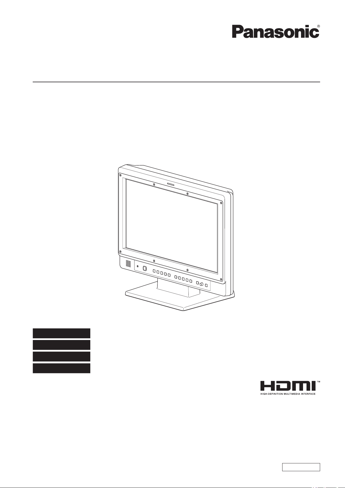
LCD Video Monitor
Model No.
Model No.
BT-LH1850P
BT-LH1850E
DEUTSCH
FRANÇAIS
ITALIANO
ESPAÑOL
Before operating this product, please read the instructions carefully and save this manual for future use.
SS0112KT0 -PS
Printed in Japan
Für Erlauterungen in Deutsch, konsultieren Sie bitte die mitgelieferte CD-ROM.
Pour des explications en français, veuillez vous reporter au CD-ROM fourni.
Per le istruzioni in italiano, vedere il CD-ROM in dotazione.
Para la explicación en español, consulte el CD-ROM suministrado.
ENGLISH
VQT4F03
Page 2
3
Read this first ! (for BT-LH1850P)
CAUTION:
The mains plug of the power supply cord shall remain readily operable.
The AC receptacle (mains socket outlet) shall be installed
near the equipment and shall be easily accessible. To completely disconnect this equipment from the AC mains, disconnect the power cable plug from the AC receptacle.
CAUTION:
In order to maintain adequate ventilation, do not install or
place this unit in a bookcase, built-in cabinet or any other
confined space. To prevent risk of electric shock or fire hazard due to overheating, ensure that curtains and any other
materials do not obstruct the ventilation.
CAUTION:
To reduce the risk of fire or electric shock and annoying
interference, use the recommended accessories only.
CAUTION:
This apparatus can be operated at a voltage in the range of
WARNING:
This equipment must be grounded.
To ensure safe operation, the three-pin plug must be inserted only into a standard three-pin power outlet which
is effectively grounded through normal household wiring.
Extension cords used with the equipment must have three
cores and be correctly wired to provide connection to the
ground. Wrongly wired extension cords are a major cause
of fatalities. The fact that the equipment operates satisfactorily does not imply that the power outlet is grounded or
that the installation is completely safe. For your safety, if
you are in any doubt about the effective grounding of the
power outlet, please consult a qualified electrician.
WARNING:
• To reduce the risk of fire or electric shock, do not expose
this equipment to rain or moisture.
• To reduce the risk of fire or electric shock hazard, keep
this equipment away from all liquids. Use and store only in
locations which are not exposed to the risk of dripping or
splashing liquids, and do not place any liquid containers
on top of the equipment.
100 - 240 V AC. Voltages other than 120 V are not intended
for U.S.A. and Canada.
CAUTION:
Excessive sound pressure from earphones and headphones can cause hearing loss.
CAUTION:
This Monitor is for use only with Panasonic Wall Mount
Adaptor, BT-WMA17G. Use with other Wall Mount or Rack
Mount Adaptor is capable of resulting in instability causing
possible injury.
CAUTION:
Check the installation at least once a year.
An improper installation could cause the monitor to fall off
resulting in personal injury.
CAUTION:
Remove the wall mount adaptor when not used.
Otherwise people moving in the vicinity of the monitor could
get caught on the bracket and be injured.
WARNING:
Always keep the tilt stand screws and protective panel
mounting screws out of the reach of infants and small children.
WARNING:
Installation should only be performed by qualified installation personnel.
Improper installation may result in the entire apparatus falling down and causing injury.
indicates safety information.
Notice (U.S.A. only):
Disposal may be regulated in your community due to Environmental considerations. For disposal or recycling information, please
visit Panasonic website: http://www.panasonic.com/environmental or call 1-888-769-0149.
2
Page 3

Read this first ! (for BT-LH1850P) (continued)
FCC NOTICE (USA)
This device complies with part 15 of the FCC Rules. Operation is subject to the following two conditions:
(1) This device may not cause harmful interference, and (2) this device must accept any interference received, including interference that may cause undesired operation
CAUTION:
This equipment has been tested and found to comply with the limits for a class A digital device, pursuant to Part 15 of the FCC
Rules. These limits are designed to provide reasonable protection against harmful interference when the equipment is operated
in a commercial environment. This equipment generates, uses, and can radiate radio frequency energy and, if not installed and
used in accordance with the instruction manual, may cause harmful interference to radio communications.
Operation of this equipment in a residential area is likely to cause harmful interference in which case the user will be required to
correct the interference at his own expense.
Warning:
To assure continued FCC emission limit compliance, the user must use only shielded interface cables when connecting to
external units. Also, any unauthorized changes or modifications to this equipment could void the user’s authority to operate it.
indicates safety information.
IMPORTANT SAFETY INSTRUCTIONS
1) Read these instructions.
2) Keep these instructions.
3) Heed all warnings.
4) Follow all instructions.
5) Do not use this apparatus near water.
6) Clean only with dry cloth.
7) Do not block any ventilation openings. Install in accordance with the manufacturer’s instructions.
8) Do not install near any heat sources such as radiators, heat registers, stoves, or other apparatus (including amplifiers) that produce
heat.
9) Do not defeat the safety purpose of the polarized or grounding-type plug. A polarized plug has two blades with one wider than the
other. A grounding-type plug has two blades and a third grounding prong. The wide blade or the third prong are provided for your
safety. If the provided plug does not fit into your outlet, consult an electrician for replacement of the obsolete outlet.
10) Protect the power cable from being walked on or pinched particularly at plugs, convenience receptacles, and the point where they
exit from the apparatus.
11) Only use attachments/accessories specified by the manufacturer.
12) Use only with the cart, stand, tripod, bracket, or table specified by the manufacturer, or sold with the apparatus. When
a cart is used, use caution when moving the cart/apparatus combination to avoid injury from tip-over.
13) Unplug this apparatus during lightning storms or when unused for long periods of time.
14) Refer all servicing to qualified service personnel. Servicing is required when the apparatus has been damaged in any
way, such as power-supply cord or plug is damaged, liquid has been spilled or objects have fallen into the apparatus,
the apparatus has been exposed to rain or moisture, does not operate normally, or has been dropped.
Page 4
5
Read this first ! (for BT-LH1850E)
WARNING:
This equipment must be earthed.
To ensure safe operation, the three-pin plug must be inserted only into a standard three-pin power point which is
effectively earthed through normal household wiring.
Extension cords used with the equipment must have three
cores and be correctly wired to provide connection to the
earth. Wrongly wired extension cords are a major cause of
fatalities. The fact that the equipment operates satisfactorily does not imply that the power point is earthed or that the
installation is completely safe. For your safety, if you are in
any doubt about the effective earthing of the power point,
please consult a qualified electrician.
WARNING:
• To reduce the risk of fire or electric shock, do not expose
this equipment to rain or moisture.
• To reduce the risk of fire or electric shock hazard, keep
this equipment away from all liquids. Use and store only in
locations which are not exposed to the risk of dripping or
splashing liquids, and do not place any liquid containers
on top of the equipment.
WARNING:
Always keep the tilt stand screws and protective panel
mounting screws out of the reach of infants and small children.
WARNING:
Installation should only be performed by qualified installation personnel.
Improper installation may result in the entire apparatus falling down and causing injury.
CAUTION:
Do not remove panel covers by unscrewing them.
To reduce the risk of electric shock, do not remove covers.
No user serviceable parts inside.
Refer servicing to qualified service personnel.
CAUTION:
The mains plug of the power supply cord shall remain readily operable.
The AC receptacle (mains socket outlet) shall be installed
near the equipment and shall be easily accessible. To completely disconnect this equipment from the AC mains, disconnect the power cable plug from the AC receptacle.
CAUTION:
To reduce the risk of fire or electric shock and annoying
interference, use the recommended accessories only.
CAUTION:
In order to maintain adequate ventilation, do not install or
place this unit in a bookcase, built-in cabinet or any other
confined space. To prevent risk of electric shock or fire hazard due to overheating, ensure that curtains and any other
materials do not obstruct the ventilation.
CAUTION:
Excessive sound pressure from earphones and headphones can cause hearing loss.
CAUTION:
This Monitor is for use only with Panasonic Wall Mount
Adaptor, BT-WMA17G. Use with other Wall Mount or Rack
Mount Adaptor is capable of resulting in instability causing
possible injury.
CAUTION:
Check the installation at least once a year.
An improper installation could cause the monitor to fall off
resulting in personal injury.
CAUTION:
Remove the wall mount adaptor when not used.
Otherwise people moving in the vicinity of the monitor could
get caught on the bracket and be injured.
indicates safety information.
EEE Yönetmeliğine Uygundur.
EEE Complies with Directive of Turkey.
4
Page 5
Read this first ! (for BT-LH1850E) (continued)
Caution for AC Mains Lead
FOR YOUR SAFETY PLEASE READ THE FOLLOWING TEXT CAREFULLY.
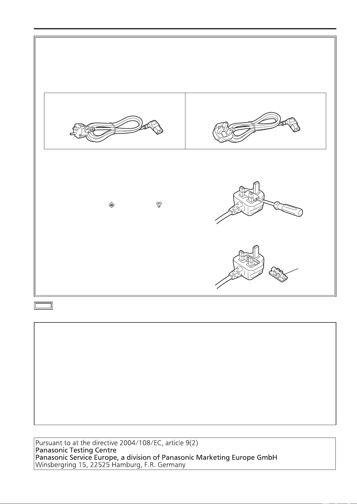
This product is equipped with 2 types of AC mains cable. One is for continental Europe, etc. and the other one is only
for U.K.
Appropriate mains cable must be used in each local area, since the other type of mains cable is not suitable.
FOR CONTINENTAL EUROPE, ETC.
Not to be used in the U.K.
FOR U.K. ONLY
FOR U.K. ONLY
This appliance is supplied with a moulded three pin
mains plug for your safety and convenience.
A 13 amp fuse is fitted in this plug.
Should the fuse need to be replaced please ensure that
the replacement fuse has a rating of 13 amps and that it
is approved by ASTA or BSI to BS1362.
Check for the ASTA mark or the BSI mark
body of the fuse.
If the plug contains a removable fuse cover you must
ensure that it is refitted when the fuse is replaced.
If you lose the fuse cover the plug must not be used
until a replacement cover is obtained.
A replacement fuse cover can be purchased from your
local Panasonic Dealer.
on the
How to replace the fuse
1.Open the fuse compartment with a screwdriver.
2.Replace the fuse.
Fuse
indicates safety information.
Note regarding the Power Management function specified under COMMISSION REGULATION (EC)
No 1275/2008 implementing Directive 2009/125/EC of the European Parliament and of the Council.
This device is designed and manufactured for use at a broadcasting station and/or in a similar environment.
This device is not equipped with a Power Management function or the Power Management function is set to OFF as it will prevent
the device from fulfilling its intended purpose for the reasons below.
1. If the device is a Studio Camera, a Weather Camera, a Mixer or other processor:
A Power Management function may cause the device to suddenly stop during recording or while On Air.
2. If the device is a Studio Monitor:
A Power Management function may cause video for the confirmation of whether a signal is normal, or whether the signal has
been lost, to be un-viewable.
3. If the device is a Camera Recorder:
A professional camera recorder must be able to start quickly at any time, but a Power Management function will cause an increase in the time taken to resume from Stand-by mode.
Page 6
Read this first ! (for BT-LH1850E) (continued)
EMC NOTICE FOR THE PURCHASER/USER OF THE APPARATUS
1. Applicable standards and operating environment
The apparatus is compliant with:
• standards EN55103-1 and EN55103-2 2009, and
• electromagnetic environments E1, E2, E3 and E4.
2. Pre-requisite conditions to achieving compliance with the above standards
<1> Peripheral equipment to be connected to the apparatus and special connecting cables
• The purchaser/user is urged to use only equipment which has been recommended by us as peripheral equipment to be
connected to the apparatus.
• The purchaser/user is urged to use only the connecting cables described below.
<2> For the connecting cables, use shielded cables which suit the intended purpose of the apparatus.
• Video signal connecting cables
Use double shielded coaxial cables, which are designed for 75-ohm type high-frequency applications, for SDI (Serial Digital Interface).
Coaxial cables, which are designed for 75-ohm type high-frequency applications, are recommended for analog video
signals.
• Audio signal connecting cables
If your apparatus supports AES/EBU serial digital audio signals, use cables designed for AES/EBU.
Use shielded cables, which provide quality performance for high-frequency transmission applications, for analog audio
signals.
• Other connecting cables (IEEE1394, USB)
Use shielded cables, which provide quality performance for high-frequency applications, as connecting cables.
• When connecting to the DVI signal terminal, use a cable with a ferrite core.
• If your apparatus is supplied with ferrite core(s), they must be attached on cable(s) following instructions in this manual.
3. Performance level
The performance level of the apparatus is equivalent to or better than the performance level required by these standards.
However, the apparatus may be adversely affected by interference if it is being used in an EMC environment, such as an area
where strong electromagnetic fields are generated (by the presence of signal transmission towers, cellular phones, etc.). In order
to minimize the adverse effects of the interference on the apparatus in cases like this, it is recommended that the following steps
be taken with the apparatus being affected and with its operating environment:
1. Place the apparatus at a distance from the source of the interference.
2. Change the direction of the apparatus.
3. Change the connection method used for the apparatus.
4. Connect the apparatus to another power outlet where the power is not shared by any other appliances.
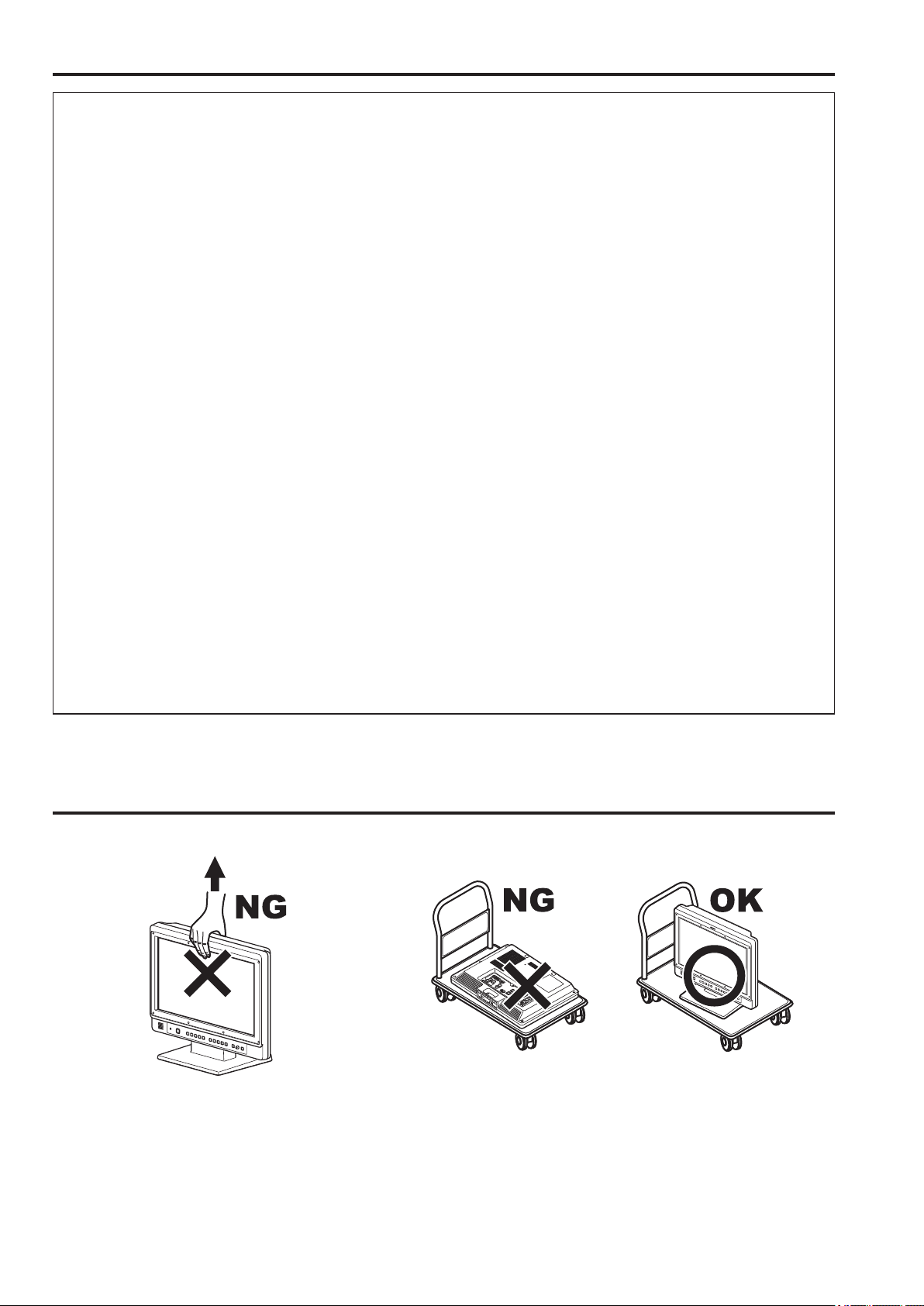
Transportation precautions
Do not try to lift the monitor by grabbing the LCD panel. Do not place the monitor face down during transportation to prevent
damaging it. Keep it upright.
Do not expose the LCD panel to strong pressure or pressure from pointed objects. Take care especially during transportation.
Exposing the LCD panel to strong pressure may result in blurring or other damage.
6
Page 7

About this instruction manual
• This instruction manual refers to BT-LH1850P/1850E as “this unit.”
• The illustrations, explanatory drawings, and other figures included in this instruction manual are for illustrative purposes only and may
differ from actual display.
• HDMI, the HDMI logo, and High-Definition Multimedia Interface are trademarks or registered trademarks of HDMI Licensing, LLC in
the United States and/or other countries.
• Adobe
• In this manual, references to pages are indicated as (→page 00).
®
Reader® is a trademark of Adobe Systems Incorporated.
Precautions for Use
• The LCD monitor is manufactured with high-precision technology and has an effective pixel count of over 99.99 %. However, less than
0.01 % of pixels may be stuck or dead in some cases. This is not a malfunction and has no effect on the recorded images.
• If a still image is displayed for an extended period of time, it may generate a temporary afterimage (phosphor burn-in). (However, such
images can be removed by displaying normal video for a while.)
• The response speed and brightness of liquid crystal vary with ambient temperatures.
• Do not install the unit in a place exposed to direct sunlight, as it may damage the cabinet and the LCD screen.
• Do not install the unit in locations where enough space cannot be provided around it as heat may build up inside preventing normal
operation. Be sure to provide enough space around the unit.
• Exposing the LCD screen to intense light sources will impair its characteristics and lower image quality.
• In an environment exposed to drastic temperature fluctuations, condensation may build up on and inside the LCD screen. This may
lower the quality of the screen and may damage it.
• Some video images may appear blurred on the screen.
• Leaving the unit in a location exposed to high temperature or humidity for an extended period of time may damage the LCD screen
and cause blurring.
• Streaks of light may be seen in the area between the edge of the screen and the frame; this is normal and not a malfunction.
• The front panel is fitted with a packaging material to prevent damage to the LCD panel when taking it out of the packing case or transporting it. Remove the panel before use.
• This unit does not support VIERA Link. If the unit is connected to a VIERA-Link-compatible device via an HDMI cable, VIERA Link
functions on the other device may not operate properly.
• Using the unit near a wireless transmitter, high-voltage equipment, a speaker, large motors or other devices or exposing it to static
electricity could cause electromagnetic interference and distort audio and video reception.
7
Page 8

9
Contents
Read this first ! (for BT-LH1850P) ...........................................2
Read this first ! (for BT-LH1850E) ...........................................4
Transportation precautions .....................................................6
About this instruction manual .................................................7
Precautions for Use..................................................................7
Standard accessories · Optional units ...................................8
About PDF manuals .................................................................9
Opening the Operating Instructions .........................................9
Outline .......................................................................................9
Dimensions .............................................................................10
Controls and Their Functions ...............................................11
Video monitor ........................................................................11
Front panel ............................................................................11
Rear panel .............................................................................12
Power supply ..........................................................................13
Connecting the power cable ..................................................13
Adjusting monitor angle ........................................................13
Detaching and Attaching the Tilt Stand ...............................14
Detaching the tilt stand ..........................................................14
Attaching the tilt stand ...........................................................14
On-screen Display ..................................................................14
Operating status display ........................................................14
Main menu, FUNCTION menu,
INPUT SELECT menu indications .....................................15
Picture adjusting menu ..........................................................15
Audio volume display ............................................................15
Sharpness display .................................................................16
FUNCTION display ................................................................16
Audio level meter display ......................................................16
Time code (TC) display .........................................................17
Closed caption (CC) display ..................................................17
In monitor display (IMD) display ............................................17
How to Use the On Screen Menu ..........................................18
Main menu .............................................................................18
FUNCTION menu ..................................................................18
INPUT SELECT menu ...........................................................18
Picture adjusting menu ..........................................................19
Audio volume .........................................................................19
User Data .................................................................................20
Saving user data ...................................................................20
Loading user data ..................................................................20
Main menu ...............................................................................21
Menu configuration ................................................................21
MARKER ...............................................................................22
Types of MARKER ................................................................24
VIDEO CONFIG ....................................................................25
SYSTEM CONFIG .................................................................27
Performing AUTO CALIBRATION .........................................29
RESET operation ..................................................................30
FUNCTION ............................................................................30
GPI ........................................................................................37
INPUT SELECT .....................................................................38
AUDIO ...................................................................................39
DISPLAY SETUP ..................................................................40
CONTROL .............................................................................41
HOURS METER ....................................................................41
Setting Item Restrictions .......................................................42
REMOTE Specifications .........................................................44
GPI input terminal ..................................................................44
RS-232C input terminal .........................................................45
RS-485 input/output terminal .................................................46
Error and Warning Displays ..................................................51
Maintenance ............................................................................51
Specifications .........................................................................52
INDEX.......................................................................................56
Standard accessories · Optional units
Standard accessories
Power cable x 1(BT-LH1850P)
Power cable x 2(BT-LH1850E)
CD-ROM x 1
• The unit is shipped with the following accessories attached.
Tilt stand x 1
Tilt stand screws x 4
Protective panel mounting screws x 8, M3, 8 mm long
(The customer can use these screws for permanent attachment of a protective panel designed for the monitor.)
(Tighten the screws to a tightening torque not exceeding 30 N cm)
• After unpacking the monitor, dispose of the AC cord cap (BT-LH1850E only) and packaging material in an appropriate manner.
Optional units
• BT-WMA17G wall mount adapter (Leave installation of the wall mount adaptor to authorized personnel.)
8
Page 9

About PDF manuals
Supplied CD-ROM is provided with Operating Instructions which are in the form of a PDF(Portable Document Format) file.
• You need to have the Adobe
• Download the Adobe
• Refer to the Help menu for details about Adobe
®
®
Reader® installed to open and view PDF files.
Reader® properly to your computer from the Adobe web site(http://www.adobe.com/).
®
Reader®.
Opening the Operating Instructions
1.
Insert the CD-ROM disc into the CD-ROM drive.
2. If the software installation screen opens, click [Cancel] to cancel the installation. To open the CD-ROM, double-click the My
Computer icon, right click the CD-ROM drive icon, and then click [Open] in the displayed shortcut menu.
3. Double-click on the [INDEX.pdf] file on the CD-ROM.
• The Adobe
®
Reader® will start up, and a list of contents for the Operating Instructions will be displayed.
4. Click on a desired document name.
• The Operating Instructions selected will open.
Outline
The BT-LH1850P/1850E is a compact, flat panel LCD monitor for broadcast and industrial applications, equipped with a 47 cm (18.5
1
in.)
liquid crystal display.
*
Effective display area measured diagonally.
*1
High Performance Liquid Crystal Panel
This product incorporates a wide WXGA (1366 x 768) LCD panel. It offers excellent color reproduction, a wide viewing angle, and a
fast response time.
Superb Moving Image Quality Achieved by New Image Processing Engine
• A 3D Look Up Table (LUT) and a 10-bit image processing engine facilitate accurate and smooth gradation from low to high brightness levels.
• The incorporation of an I/P conversion circuit with a low delay of less than one field minimizes the delay time between signal input
and monitor display.
• The incorporation of diagonal line compensation circuit reduces image degradation in the vertical direction and jagged noise on
diagonal lines.
• The high-speed moving image response time provides vivid and clear image display.
• Gamma compensation is performed for each monitor.
Wide Variety of Functions and Interfaces
• Equipped with SDI (HD/SD compatible), HDMI, VIDEO, and DVI-I inputs.
• FOCUS-IN-RED function (Displayed abbreviated to F-IN-R in the picture adjusting knob status display.)
Making camera focus adjustments is extremely easy because the section of the image in focus is displayed in red to make it easy
to understand what is in focus.
• WFM (Y/R/G/B) and vectorscope display functions
Capable of input signal Y/R/G/B waveform display (when SDI, HDMI, VIDEO, or DVI-I input) and vectorscope display (when SDI input).
• Audio level meter display function
There are level displays for embedded SDI and HDMI audio signals and analog audio signals. Furthermore, support is also included
for reference point setting, peak hold, and overrange display.
The incorporation of a speaker and a HEADPHONES output jack means you can check the audio. The channel can also be selected in a menu.
• Closed caption function
The captions added to video signals can be displayed during SDI and VIDEO input.
• 2-screen display function
The screen can be split into two to allow you to make a screen comparison for the same input connectors and same format.
• PIXEL TO PIXEL function
This function makes camera focus adjustment extremely easy because the input signals are displayed without being resized.
When resizing is not performed, the 1080/60i signals can be expanded to the equivalent of an approximately 26-inch wide monitor,
and then checked.
• Cross hatch display function
This function displays markers at regular vertical and horizontal intervals to facilitate easy composition.
• External remote control
RS-485, RS-232C and GPI remote control terminals are provided.
A loop-through connection using the RS-485 input and output terminals allows control of multiple monitors (up to 32 monitors).
• In monitor display function
The RS-485 interface allows you to display text and the tally indication on the monitor.
• Tilt Stand
A tilt monitor stand is provided as standard.
You can tilt the monitor backwards and forwards to find the angle that best suits your viewing needs.
9
Page 10
11
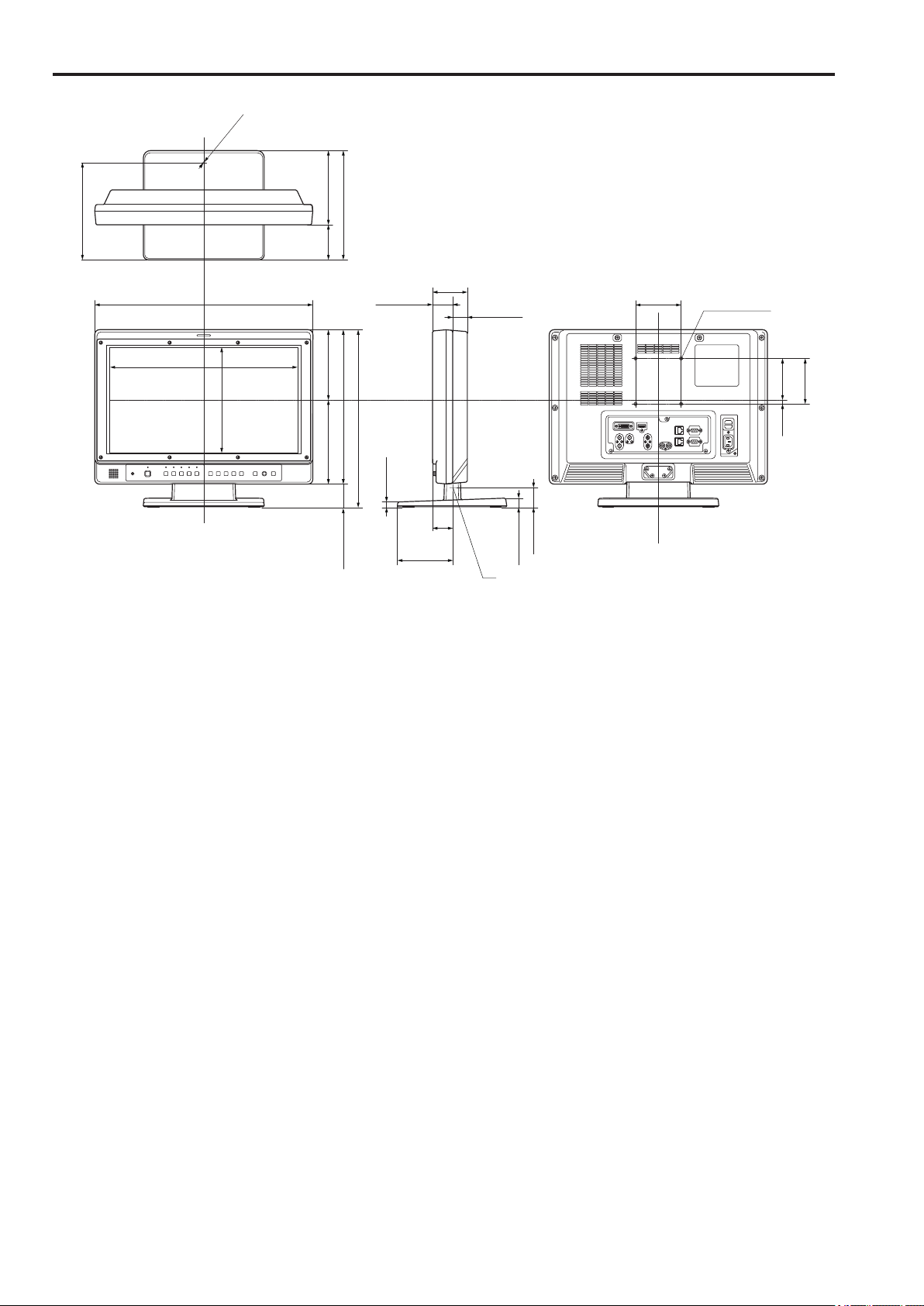
Dimensions
Unit: mm (inches)
φ3.5 (1/8)
213.3 (8-3/8)
163 (6-7/16)
77
(3-1/16)
240 (9-7/16)
411.4 (16-3/16)
479 (18-7/8)
232 (9-1/8)
154.3 (6-1/16)184.7 (7-1/4)
339 (13-3/8)
390.7 (15-3/8)
51.7 (2-1/16)
44.3 (1-3/4)
12.5 (1/2)
(4-13/16)
(1-3/4)
121.9
76.5 (3)
44.9
32.2 (1-1/4)
20.6 (13/16)
Center of tilt rotation
44 (1-3/4)
100
(3-15/16)
4-M4 P=0.7
Depth 20 (Max)
91.3
8.7
100
(3-5/8)
(5/16)
(3-15/16)
• When installing the monitor in one place permanently, we recommend that you fix the monitor in place using the screw holes on the
back of the stand.
10
Page 11
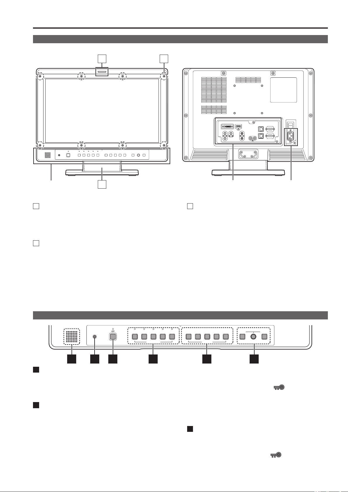
Controls and Their Functions
Video monitor
Front panel Rear panel
1
Front panel
(This page)
Tally Lamps (Red and Green)
1
Can be lit by a control signal (red tally and green tally) from
a GPI/camera.
If the red tally and green tally light at the same time, the tally
color will become amber.
Protective panel mounting screw holes (8 holes)
2
Eight screw holes have been provided to enable attachment
of a permanent protection panel. The screws for the protective panel are installed in the mounting screw holes at time
of shipment. To attach a protective panel, first remove the
screws before securing the panel.
<Note>
The LCD panel is shipped covered with a packaging material
to protect it from damage during unpacking and transportation. Remove the panel before using the monitor.
3
2
Rear panel
(→page 12)
Tilt Stand
3
The tilt stand allows you tilt the unit approx. 10 degrees forward or approx. 15 degrees backward.
When tilting the unit, firmly hold the bottom of the stand and
move the top of the unit.
If you want to remove the tilt stand, refer to “Detaching and
Attaching the Tilt Stand” (→page14).
<Note>
• When tilting the monitor, be careful not to trap your hand
between the monitor and stand.
Power supply
(you can switch between AC
and DC (→page 13))
Front panel
HEADPHONES VIDEO SDI 1
SDI 2 HDMI DVI-I 1 2
INPUT SELECT
5 6 1 2 3 4
POWER switch
1
Switches the power supply ON/OFF. When the power is ON,
the LED (green) lights.
To turn the power off, press and hold the switch for at least
three seconds.
INPUT SELECT button
2
Selects the signal input line. The green LED light above the
pressed button indicates the selected input signal.
VIDEO : Video input
SDI1 : Serial digital interface input (HD/SD compatible)
SDI2 : Serial digital interface input (HD/SD compatible)
HDMI : HDMI input (HDCP compatible)
DVI-I : DVI-I input (HDCP compatible)
• Selects one of four input signals: digital video or
PC signal, analog video or PC signal. (→page 38)
3
4 5 MENU RETURN
FUNCTION
VOLUMEPICTURE
• The input line when the power supply is switched ON is the
one that was selected the last time the power was switched
OFF.
• When the control lock is on, the
mark appears and
input lines cannot be changed. (→page 41)
• When INT-SG (internal chart for adjustment “Color Bar +
Grayscale”) is selected, all LEDs above the INPUT SELECT button are off. Use the “INPUT SELECT” menu to
select INT-SG. (→page 18)
FUNCTION button
3
FUNCTION1 to FUNCTION5:
Press to use function assigned to the FUNCTION button
with the menu.
• When the control lock is on, the
mark appears to
indicate that FUNCTION operation is disabled. (→page 41)
11
Page 12
Controls and Their Functions (continued)
MENU button, rotary knobs (with push-on switch (PIC-
4
TURE)) and RETURN/VOLUME button (→page 15)
Use these buttons to display menus, select and adjust settings and perform menu selections.
MENU: Press to display the TOP MENU (main menu,
FUNCTION menu and INPUT SELECT menu) or to
exit from a menu.
Rotary knob:
Turn the knob clockwise or counterclockwise to move
the cursor up or down or to change set values.
Press the knob to start changing set values, to con-
firm them and to open submenus.
RETURN:
Press to return to the previous menu or cancel to re-
cover a previously set value.
When no menu is open, press the rotary knob or RETURN
button to open a menu other than the TOP MENU.
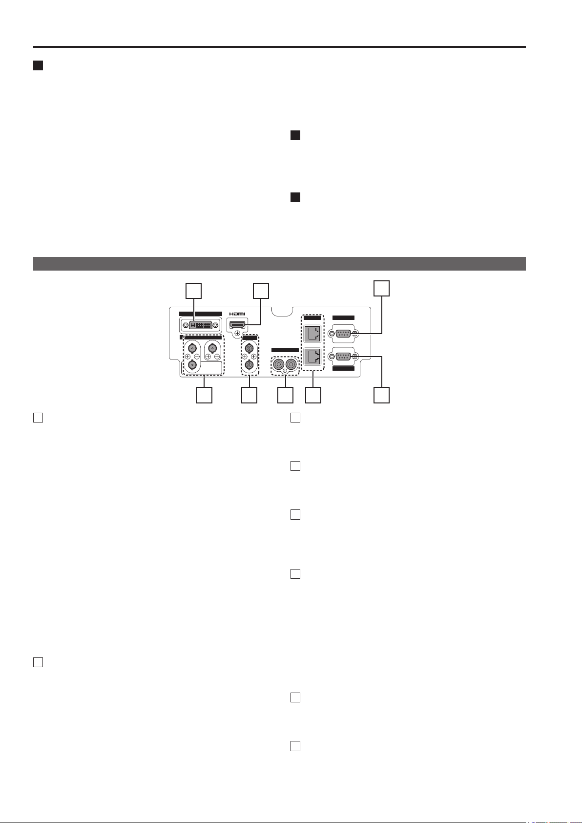
Rear panel
3
DVI-I
SDI
1 2
IN
SWITCHED
OUT
IN
OUT
VIDEO
PICTURE:
When no menu is displayed, press the rotary knob to
open the picture adjusting menu. (→page 15)
VOLUME:
When no menu is displayed, press the RETURN but-
ton to open the audio volume bar meter. (→page 15)
Speaker (monaural)
5
Enables monitoring of analog AUDIO, SDI and HDMI signal
inputs.
• Connecting headphones to the HEADPHONES output jack
turns off the speaker.
HEADPHONES output jack (M3 stereo mini jack)
6
Allows you to connect headphones to monitor analog audio,
SDI and HDMI signal input.
• The volume and sound quality differ depending on the
headphones.
4
IN
AUDIO
R L
IN
OUT
GPIRS-485
RS-232C
7
1 2 6 85
SDI terminal (BNC)
1
IN1: This is the SDI input terminal (compatible with HD/SD
automatic switching).
IN2: This is the SDI input terminal (compatible with HD/SD
automatic switching).
SWITCHED OUT: This is the active through-out terminal for
the SDI input signal being displayed on
the screen.
• Active SDI through-out is only output when [SDI1] or [SDI2]
is selected using [INPUT SELECT]. It is not output when
something other than SDI is selected. Embedded audio is
also supported.
When this output is used to daisy-chain
the quality of the original signal, cable length, the number
of connected devices and other factors all come into play to
deteriorate picture quality and introduce noise.
Daisy-chain:
*1
Refers to connecting the through-out signal from a device
to the input of a second, third or more devices in a linear
series, thus using a single signal in multiple devices.
• Use a 5C-FB or equivalent cable to make connections to
an SDI terminal.
VIDEO terminal (BNC)
2
*2*
3
IN: This is the VIDEO signal (composite signal) input ter-
minal.
OUT: This is the input signal through-out terminal.
Unless a cable is connected to the OUT terminal, the VID-
*2
EO IN terminal is automatically terminated at 75 Ω. Connecting a cable releases this termination.
Since a connection to the through-out terminal releases
*3
the 75 Ω termination of the unit, the level of the VIDEO
signal input to the unit may become too large depending
on the connected device.
1
multiple monitors,
*
DVI-I terminal (single link)
3
This is the DVI-signal input terminal.
• Use double shielded cable for making connections to a
DVI-I terminal.
HDMI terminal (Type A)
4
This is the HDMI input terminal.
• Use double-shielded cable for making connections to an
HDMI terminal.
AUDIO input terminal (pin jack)
5
This is the common audio input terminal for all video input
terminals.
• Use shielded cable for making connections to an AUDIO
input terminal.
RS-485 input/output terminal (RJ-45)
6
External control is possible by using an RS-485 signal.
• Use shielded cable for making connections to an RS-485
input/output terminal.
• Make sure that the cable is fully inserted in the terminal and
that it cannot easily be pulled out.
• A loop-through connection using the RS-485 IN/OUT terminals allow operation of multiple monitors (up to 32 monitors)
connected to the RS-485 IN/OUT terminals.
• Connect a terminator (120 Ω) between the first and second
pin of the OUT terminal on the last monitor in the chain.
GPI input terminal (D-SUB, 9 pins)
7
External control is possible by using a GPI signal.
• Use shielded cable for making connections to a GPI input
terminal.
RS-232C input terminal (D-SUB, 9 pins)
8
External control is possible by using a RS-232C signal
• Use shielded cable for making connections to an RS-232C
input terminal.
12
Page 13
Power supply
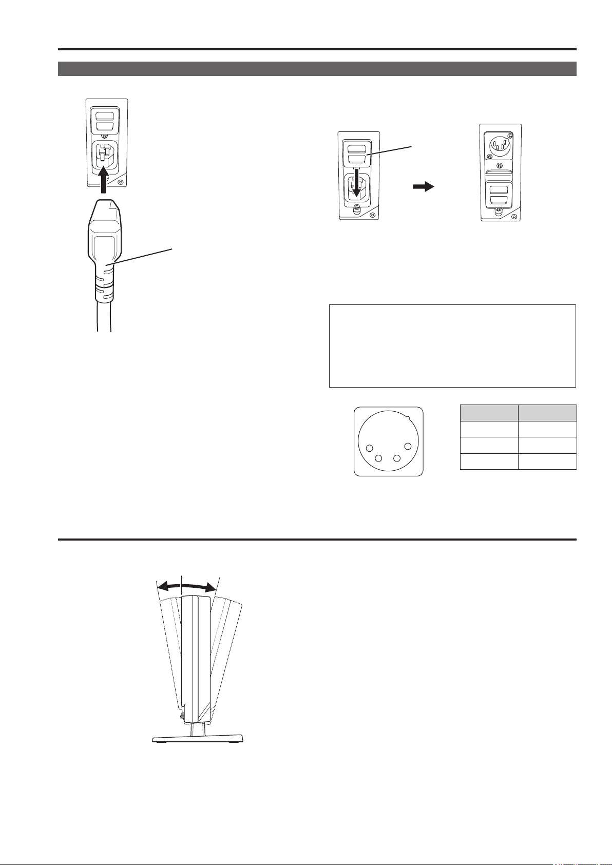
Connecting the power cable
1.
Attach the power cable to the unit.
When using external DC power (12 V DC)
You can slide open the power cover to switch from AC input to
external DC input.
Power cover
Power cable
2. Connect the power cable to an AC outlet.
Adjusting monitor angle
<Note>
• If the power cover has come off or been removed, do not use
the monitor with the power supply connected to both AC input
and DC input terminals.
• Use a shielded DC cable that is not longer than 2 m. A cable
that is 2 m or longer may cause noise.
If an external DC power supply is used, be sure to check that
the rating of the external DC power supply suits the power
requirements of this unit.
When using external DC power (12 V DC), check the external
DC input terminal pin signal, and use the correct polarity. If
a +12 V power supply is accidentally connected to the GND
terminal, this could cause a fire or personal injury.
Pin number Signal
1
External DC input terminal
4
2 3
1 GND
2, 3 ―
4 +12 V
Move the unit in the direction of the arrows to adjust it to a comfortable viewing position.
Approx. 15 degreesApprox. 10 degrees
Forward Backward
• The tilt stand allows you to tilt the unit approx. 10 degrees forward and approx. 15 degrees backward.
13
Page 14
15
Detaching and Attaching the Tilt Stand
The tilt stand is detachable.
• When detaching and attaching the tilt stand, it is recommended that you place the unit flat on the edge of a desk or table with a soft
cloth or similar material spread underneath.
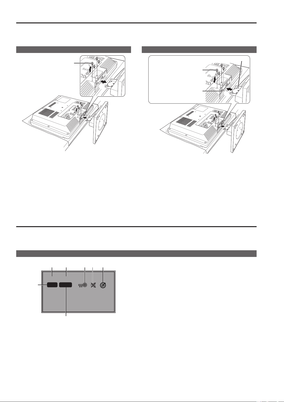
Detaching the tilt stand
Tilt stand screws
①
②
1. Unscrew the tilt stand screws (four) using a Phillips
screwdriver.
2. Detach the tilt stand.
• After detaching, please store the tilt stand and the tilt stand
screws.
Attaching the tilt stand
Plate
Tilt stand screws
②
A
①
1. Attach the tilt stand to the unit.
• Insert the plate of the tilt stand into part A (illustrated) of the
monitor unit.
2. Screw the tilt stand to the unit by screwing the tilt stand
screws (four) using a Phillips screwdriver.
(Screwing torque: Tighten to about 100 N cm or more)
On-screen Display
The screen shows the operation status display, main menu, FUNCTION menu, INPUT SELECT menu, Picture adjusting menu, audio
volume display, sharpness display, FUNCTION display, audio level meter display, time code (TC) display, closed caption (CC) display,
in monitor display(IMD) display and other information.
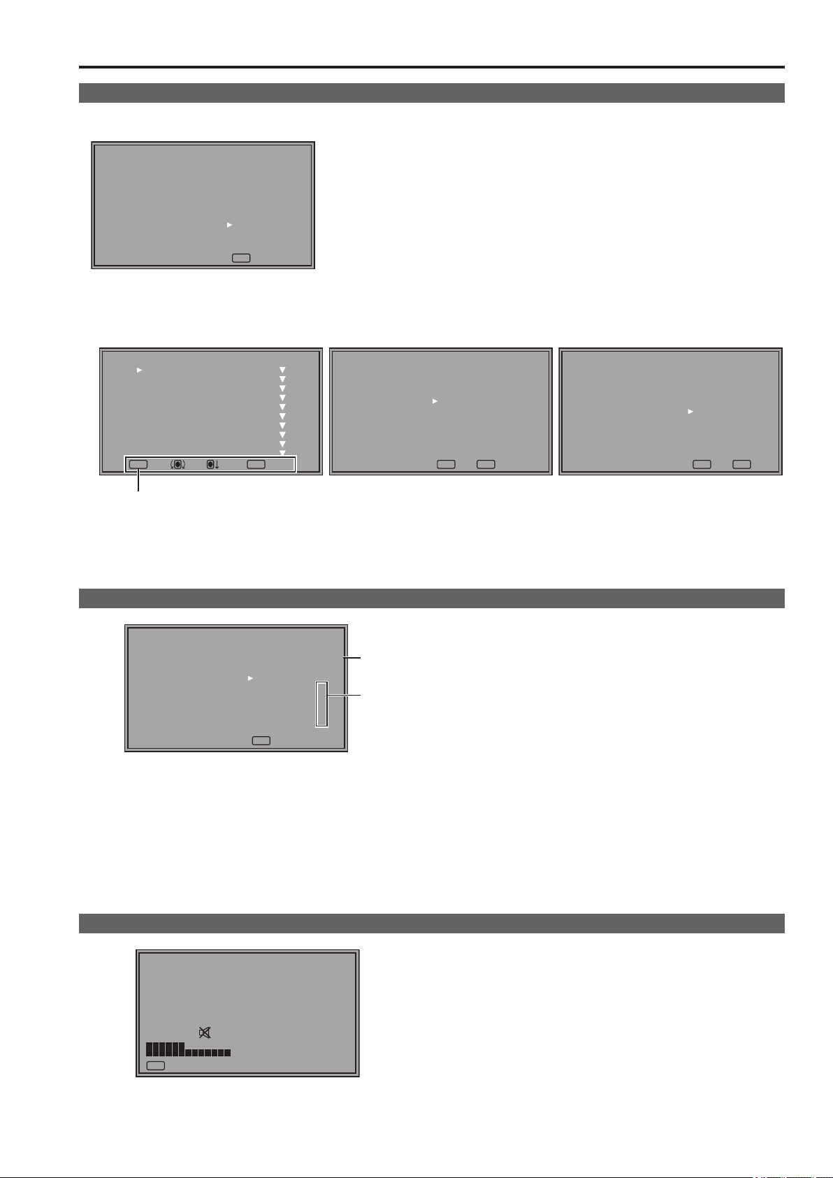
Operating status display
1 2 5 6 7
SDI1 1080/60i
3
P-P FILM
4
<Note>
• The display state of the status can be set in “STATUS DISPLAY” of the “SYSTEM CONFIG” menu (→page 27).
• “UNSUPPORT SIGNAL” and “NO SIGNAL” may not be properly displayed.
1. The selected input line (→pages 11 and 18)
• Displays VIDEO, SDI1, SDI2, HDMI, DVI-I (YP
RGB-COMP./DVI-VIDEO/DVI-COMP.) and INT-SG.
BPR/
2. Signal format
• “UNSUPPORT SIGNAL” appears if an unsupported signal is
input. It may also indicate that the format selected in the “INPUT SELECT” menu does not match the input signal.
• “NO SIGNAL” appears when no signal is input.
3. Various indications (PIXEL TO PIXEL mode)
• This indicates the PIXEL TO PIXEL mode is engaged.
4. Various indications (FILM mode)
• This indicates that “GAMMA SELECT” of the “VIDEO CONFIG” is set to “FILM.”
5. Various displays (lock setting)
• This indicates that the front operations lock is on. (→page 41)
6. Mute indication
• Indicates that the speaker and headphones are muted.
(→page 19)
7. Picture adjustment change indication
• Indicates that picture adjustments (PEAKING/PHASE/
CHROMA/BRIGHT/CONTRAST/BACKLIGHT) have been
changed from the values assigned using SETUP LOAD or
POWER ON SETUP. (→page 19)
14
Page 15
On-screen Display (continued)
Main menu, FUNCTION menu, INPUT SELECT menu indications
1.
Press MENU when no menu is displayed.
• The TOP MENU appears.
[TOP MENU]
MAIN MENU
FUNCTION
INPUT SELECT
MENU EXIT
2. Turn the rotary knob to select a menu (MAIN MENU, FUNCTION, INPUT SELECT) and press the rotary knob.
• For details on how to operate menus, refer to “How to Use the On Screen Menu” (→page18).
[MAIN MENU] [FUNCTION] [INPUT SELECT]
[MAIN MENU]
MARKER
VIDEO CONFIG
SYSTEM CONFIG
FUNCTION
GPI
INPUT SELECT
AUDIO
DISPLAY SETUP
CONTROL
HOURS METER
MENU EXIT
RETURN
RETURNSEL. ENTER
[FUNCTION]
F1:MARKER
F2:WFM/VECTOR
F3:PIXEL TO PIXEL
F4:TIME CODE
F5:LEVEL METER
MARKER ON
MENU EXIT
RETURN
RETURN
[INPUT SELECT]
VIDEO
SDI1
SDI2
HDMI
DVI-VIDEO
INT-SG
MENU EXIT
RETURN
RETURN
Displays instructions on menu button operations.
3. To close a menu, press MENU.
• It disappears after 2 minutes of inaction. (The value shown before the display clears is confirmed.)
Picture adjusting menu
1. Press rotary knob when no menu is displayed.
[PICTURE]
SETTING[USER2]
PEAKING
PHASE
CHROMA
BRIGHT
CONTRAST
BACKLIGHT
F-IN-R
MENU EXIT
*
*
A
B
A : File names called by SETUP LOAD or POWER ON SETUP
appear on the screen to the right of SETTING.
B : When picture adjustments (PEAKING/PHASE/CHROMA/
BRIGHT/CONTRAST/BACKLIGHT) have been changed
from the values assigned using SETUP LOAD or POWER
ON SETUP, an asterisk (
) appears beside the menu
*
name.
• The picture adjusting menu appears.
• For details on how to operate menus, refer to “How to Use
the On Screen Menu” (→page18)
2. To close a menu, press MENU.
• This display disappears after 10 seconds of inaction. (The
value shown before the display clears is confirmed.)
Audio volume display
[VOLUME] 30
MENU EXIT
1. Press [RETURN] when no menu is displayed.
• The audio volume bar meter appears.
• For details on how to use the audio volume, refer to “How to
Use the On Screen Menu” (→page18)
2. To close a menu, press MENU or the rotary knob.
• This display disappears after 10 seconds of inaction. (The
value shown before the display disappears is confirmed.)
Page 16
On-screen Display (continued)
17
Sharpness display
[SHARPNESS H] 14
RETURN
MENU EXIT
FUNCTION display
RETURN
[FUNCTION]
F1:MARKER
F2:WFM/VECTOR
F3:PIXEL TO PIXEL
F4:TIME CODE
F5:LEVEL METER
XXXXX
• Indicates the “SHARPNESS H/V” setting value of the “VIDEO
CONFIG” menu.
• If no operation is performed for 2 minutes, the setting value is
confirmed and the display disappears.
• Use the “FUNCTION” menu to set up functions.
• When “FUNCTION DISPLAY” (→page 31) is set to ON1 or ON2,
press any of the “FUNCTION1” to “FUNCTION5” buttons to display the status of functions assigned to the FUNCTION buttons.
• If no operation is performed for 2 seconds, the setting value is
confirmed and the display disappears.
•“XXXXX” indicates operating status (→page33 “Functions displayed during FUNCTION button operation”).
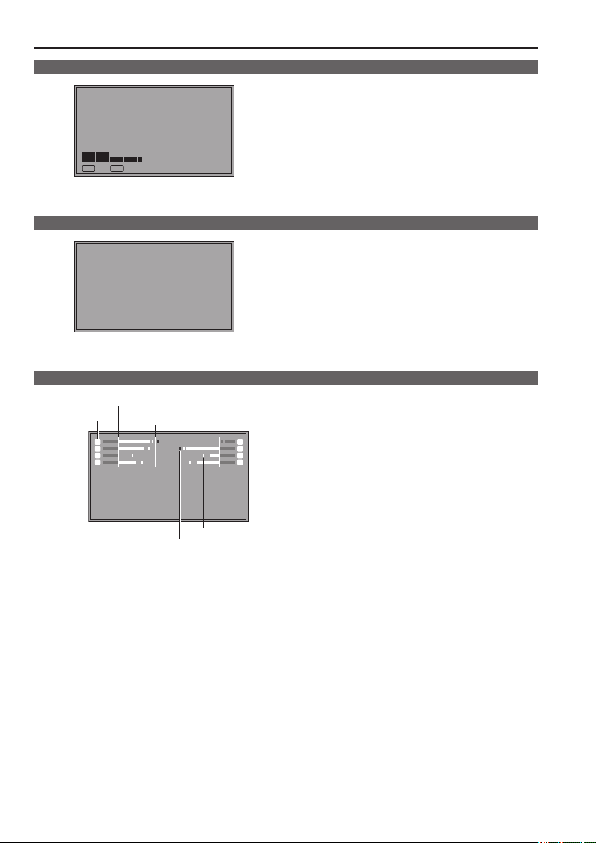
Audio level meter display
Reference point
Channel display
11
33
55
77
SDI1 1080/60i
0 dB point
Overrange
Peak hold
• A color skeleton bar meter indicates the audio level for SDI,
HDMI and AUDIO input signals.
• The display method of the audio level meter can be set in the
menu (→page 39).
22
44
66
88
Display color
Green: Up to reference point (included)
Yellow: Reference point (not included) to 0 dB point
(not included)
Red: Overrange
16
Page 17
On-screen Display (continued)
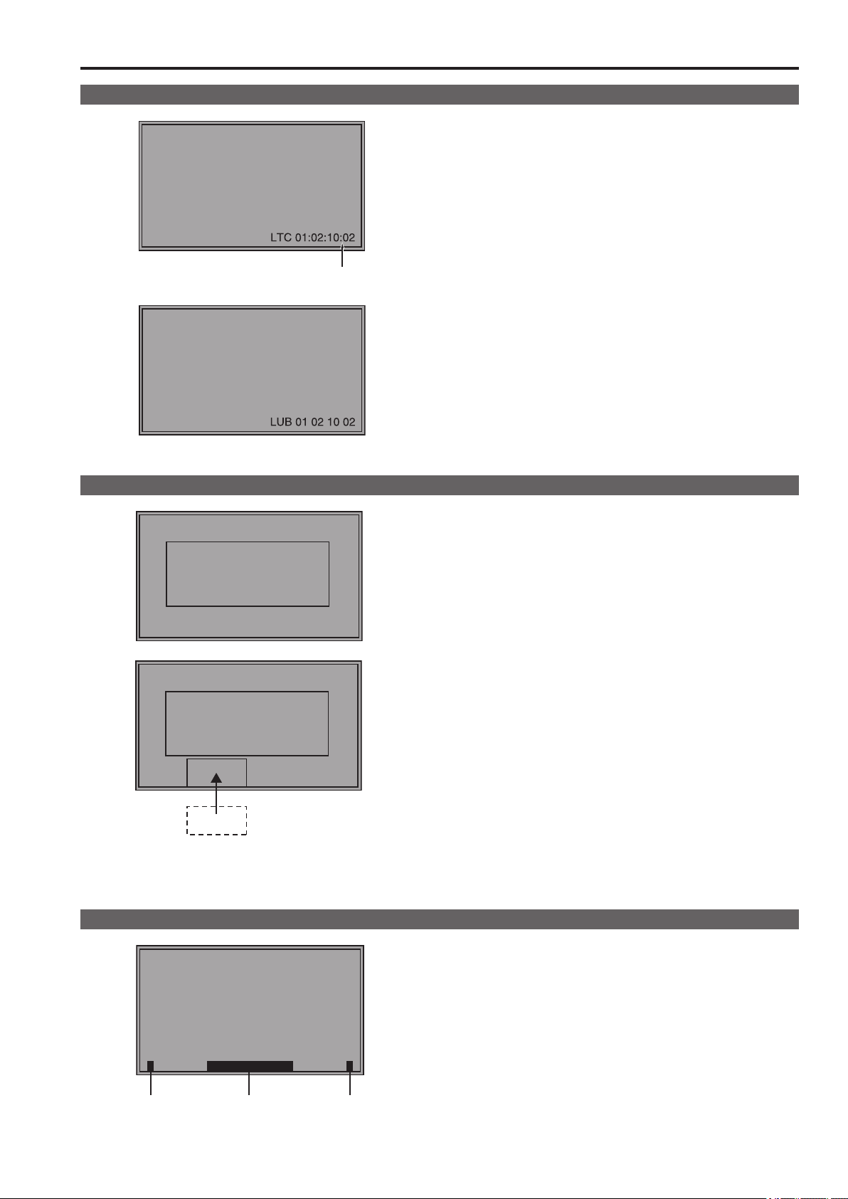
Time code (TC) display
( : ) NDF
( . ) DF
• Use the menu to display the time code for HD-SDI signal input.
It also allows you to switch display mode (LTC, VITC, LUB,
VUB). (→page 40)
In VITC and LTC display mode:
• Displays the time code as follows.
hours: minutes: seconds: frames
• In drop-frame mode, a different delimiter between seconds and
frames is used.
<Note>
Read errors are displayed as “--:--:--:--”
In VUB and LUB display modes:
• BG8, BG7, BG6, BG5, BG4, BG3, BG2, BG1 appear in the
stated order.
BG: binary group
• The (:) delimiter does not appear.
<Note>
Read errors are displayed as “-- -- -- --”
Closed caption (CC) display
Closed caption
display area
Closed caption
display area
(When the specified window extends out of the entire screen)
• Closed caption can be displayed when SDI signals and
VIDEO signals are input.
• Closed caption complies with the following standards.
• Composite Standard EIA/CEA-608 (VBI), OP-42
• SD-SDI CC Standard EIA/CEA-608 (ANC/VBI), OP-42
• HD-SDI CC Standard EIA/CEA-608 (708), EIA/CEA-708,
OP-47
• In the case of EIA/CEA-708, multiple windows can be displayed
at specified positions (up to 8).
• The display position is within a display area that is located inside the entire screen. (Refer to the following notes.)
• The display settings can be configured in the menus. You can
also select the type of closed caption, display channel (EIA/
CEA-608), and display service (EIA/CEA-708) in the menus.
(→page 40)
<Note>
• The specified window position is displayed as a position within
the display area depending on the closed caption information.
• The window may extend out of the display area depending on
the specified window position and size. In such a case, the window will be displayed but if the window also extends out of the
entire screen, the display position of the window will be changed
so that the window is displayed inside the entire screen.
In monitor display (IMD) display
CAM1
Tally-1 Tally-2Text
• This monitor supports the TSL UMD PROTOCOL (Ver. 3.1 and
Ver. 4.0) and allows you to display text and the tally indication
on the monitor using the RS-485 interface.
• For information on how to set IMD and communications, refer
to pages 41 and 46.
17
Page 18
19
How to Use the On Screen Menu
Main menu
• For details on how to display MAIN MENU, refer to “Main
menu, FUNCTION menu, INPUT SELECT menu indications”
(→page15).
1. Turn the rotary knob to select a menu item and press the
rotary knob.
[MAIN MENU]
MARKER
VIDEO CONFIG
SYSTEM CONFIG
FUNCTION
GPI
INPUT SELECT
AUDIO
DISPLAY SETUP
CONTROL
HOURS METER
MENU EXIT
RETURN
RETURNSEL. ENTER
2. Turn the rotary knob to select a submenu and press the
rotary knob.
• The settings in the submenu change to green.
[MARKER]
MARKER
16:9
4:3
BACK
CENTER
CROSS
COLOR
GPI MARKER1
GPI MARKER2
MENU EXIT
OFF
4:3
OFF
NORMAL
OFF
OFF
WHITE
95%(16:9)
95%(16:9)
RETURN
RETURNSEL. ENTER
2. Press the rotary knob.
• Each press of the rotary knob changes the set value and
enables function operation.
[FUNCTION]
F1:MARKER
F2:WFM/VECTOR
F3:PIXEL TO PIXEL
F4:TIME CODE
F5:LEVEL METER
MARKER ON
MENU EXIT
RETURN
RETURN
3. To return to the previous screen, press [RETURN].
INPUT SELECT menu
• For details on how to display the INPUT SELECT menu, refer
to “Main menu, FUNCTION menu, INPUT SELECT menu
indications” (→page15).
1. Turn the rotary knob to select an input signal or INT-SG
and press the rotary knob.
• To cancel, press [RETURN] before pressing the rotary knob.
[INPUT SELECT]
VIDEO
SDI1
SDI2
HDMI
DVI-VIDEO
INT-SG
MENU EXIT
RETURN
RETURN
3. Turn the rotary knob to select a set value and press the
rotary knob.
• To cancel, press [RETURN] before pressing the rotary knob.
[MARKER]
MARKER
16:9
4:3
BACK
CENTER
CROSS
COLOR
GPI MARKER1
GPI MARKER2
MENU EXIT
95%(16:9)
95%(16:9)
NORMAL
WHITE
RETURN
RETURNSEL. ENTER
ON
4:3
OFF
OFF
OFF
4. To return to the previous screen, press [RETURN].
FUNCTION menu
• For details on how to display the FUNCTION menu, refer to
“Main menu, FUNCTION menu, INPUT SELECT menu indications” (→page15).
1. Turn the rotary knob to select a function item.
• Selected function item and set value appear in green.
[FUNCTION]
F1:MARKER
F2:WFM/VECTOR
F3:PIXEL TO PIXEL
F4:TIME CODE
F5:LEVEL METER
MARKER ON
MENU EXIT
RETURN
RETURN
VIDEO: Video input
SDI1 : Serial digital interface input
SDI2 : Serial digital interface input
HDMI: HDMI input (HDCP compatible)
DVI-VIDEO
INT-SG
1
: DVI-I input (HDCP compatible)
*
2
: Internal chart for adjustment [Color Bar +
*
Grayscale] (→page 55)
The name of DVI-I input terminals vary with the menu set-
*1
ting and input signal status as shown in the table below.
Input signal
status (DVI-I
terminal)
Display
Menu setting (→page 38)
DVI-I DIGITAL
ANALOG
No input
DIGITAL
VIDEO input
DVI-AUTO DIGITAL AUTO —
present
DIGITAL
COMP. input
present
DVIVIDEO
DVICOMP.
YP
BPR
RGBCOMP.
DIGITAL
ANALOG —
VIDEO
COMP.
—
YP
BPR
RGB-
COMP.
—
When DVI-I [DIGITAL] or DIGITAL [AUTO] is selected in a
menu, the DVI-I input terminal name is displayed only as
DVI-AUTO. INPUT NAME SETUP in the SYSTEM CONFIG
menu cannot be used to change names.
It is not possible to switch to INT-SG in a split-screen dis-
*2
play using the SUB WINDOW function (→page 34).
2. To return to the TOP MENU screen, press [RETURN].
18
Page 19

How to Use the On Screen Menu (continued)
Picture adjusting menu
1.
Turn the rotary knob to select a menu item and press the
rotary knob.
• The menu closes and the set values of the selected menu
item appears.
[PICTURE]
SETTING[USER2]
PEAKING
PHASE
CHROMA
BRIGHT
CONTRAST
BACKLIGHT
F-IN-R
MENU EXIT
[PHASE] 30
RETURN
MENU EXIT
Name Function
PEAKING PEAKING 0 to 30 (0)
PHASE PHASE 0 to 60 (30)
CHROMA CHROMA 0 to 60 (30)
BRIGHT BRIGHT 0 to 60 (30)
CONTRAST CONTRAST 0 to 60 (50)
BACKLIGHT BACKLIGHT 0 to 100 (80)
F-IN-R FOCUS-IN-RED 0 to 30 (30)
The text color of set values that are factory defaults is green
and other values are white.
Set values are loaded when the monitor is turned on. However, operations and changes cannot be made in the following
conditions.
• When the control lock is on, the key mark (
and set values cannot be changed. (→page 41)
• When the MONO function is ON, [PHASE] and [CHROMA]
operations are disabled. (→page 26)
• F-IN-R is enabled during operation of the FOCUS-IN-RED
function.
• While operating HV DELAY (→page 30) (when set to any
other setting than OFF), [BRIGHT] operation is disabled.
• The “CONTRAST” and “BACK LIGHT” operations are dis-
abled in BLACK MODE.
RETURN
Adjustable range
( ): Factory default
) appears
2. Turn the rotary knob to select a set value and press the
rotary knob.
• The set value is confirmed and the menu reappears.
• To cancel, press [RETURN] before pressing the rotary knob.
[PHASE] 20
RETURN
MENU EXIT
RETURN
[PICTURE]
SETTING[USER2]
PEAKING
PHASE
CHROMA
BRIGHT
CONTRAST
BACKLIGHT
F-IN-R
MENU EXIT
*
• A mark (*) appears beside menu names whose picture
adjustments(PEAKING/CHROMA/PHASE/BRIGHT/
CONTRAST/BACKLIGHT) have been changed from the
values assigned using “SETUP LOAD” or “POWER ON
SETUP”.
Audio volume
• For details on how to display the audio volume, refer to “Audio
volume display” (→page15)
1. Turn the rotary knob to select a set value.
[VOLUME] 30
MENU EXIT
• Set value is confirmed when it is changed.
• Changing the audio volume when audio output is muted (“AUDIO MUTE” (→page30)) immediately cancels AUDIO MUTE.
•
is displayed when audio output of the monitor is muted.
• Audio volume is always available and is not affected by the
“CONTROL” menu (→page 41)
• The adjustment range is 0 to 60 (the factory default is 0)
Page 20

21
User Data
This unit can save up to five combinations of set values for main menu and screen adjustments made in the picture adjusting menu as
user data that can be recalled. You can also return settings and adjustments to their factory defaults.
User data include the following settings.
• Menu settings except “SETUP LOAD/SAVE” and “REMOTE in CONTROL” (including button function settings on the monitor front
panel)
• Screen adjustments made with the picture adjusting knob
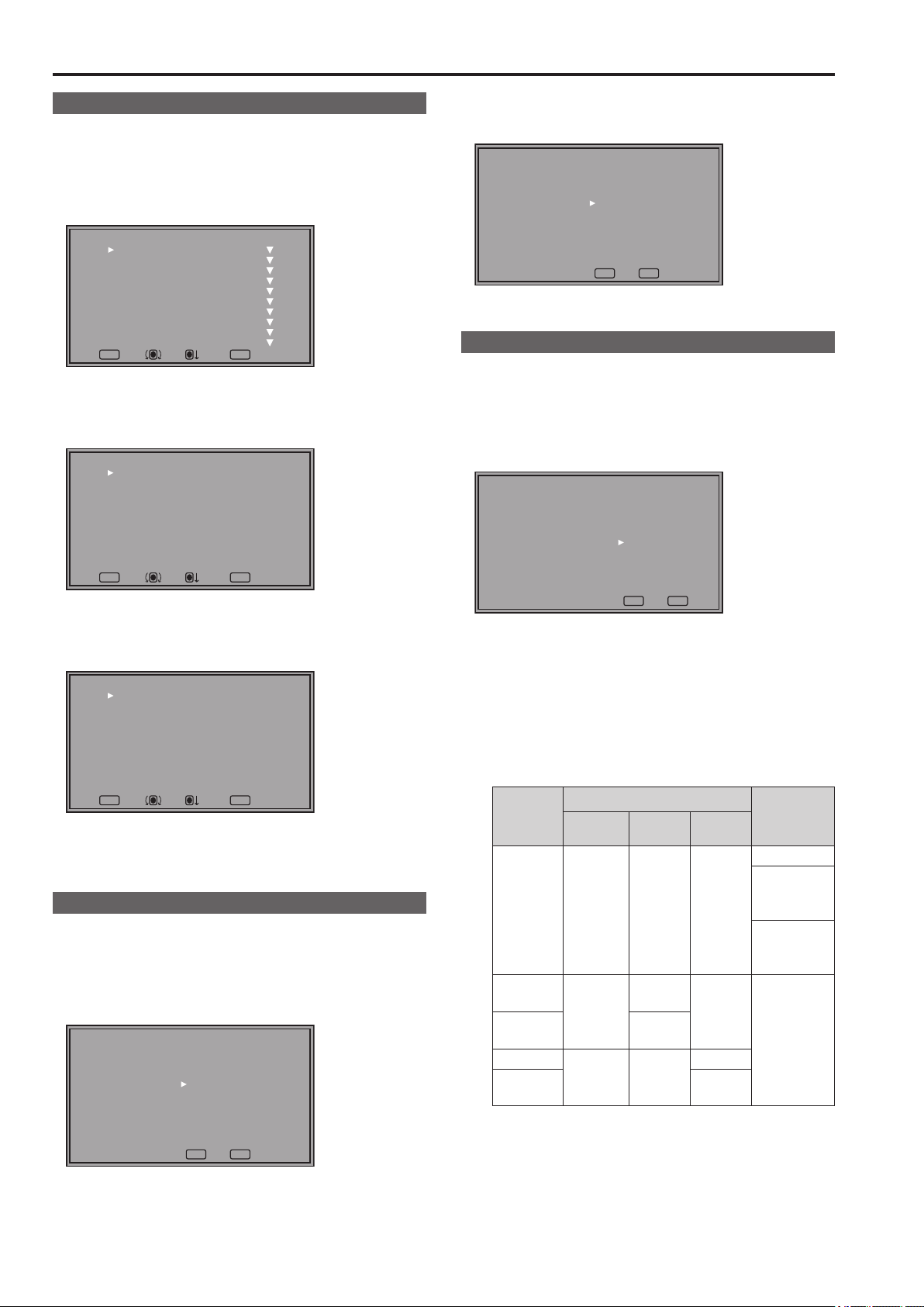
Saving user data
1.
Press [MENU] to display the main menu.
2. Turn the rotary knob to select the “SYSTEM CONFIG”
menu and press the rotary knob.
3. Turn the rotary knob to select the “SETUP SAVE” sub-
menu and press the rotary knob.
The setting in the sub menu changes to green.
[SYSTEM CONFIG]
SUB WINDOW
MENU POSITION
STATUS DISPLAY
INPUT NAME SETUP
SETUP LOAD
SETUP SAVE
POWER ON SETUP
COLOR SPACE
POWER DOWN
POWER SAVE MODE
CALIBRATION
MENU EXIT
FULL
CENTER
3SEC OFF
FACTORY
USER1
LAST
EBU
OFF
OFF
RETURN
RETURNSEL. ENTER
Changes to green
4. Turn the rotary knob to select settings to save from the
“USER1” to “USER5” and press the rotary knob.
The following screen appears.
[SETUP SAVE]
USER1
YES
NO
Loading user data
1.
Press [MENU] to display the main menu.
2. Turn the rotary knob to select the “SYSTEM CONFIG”
menu and press the rotary knob.
3. Turn the rotary knob to select the “SETUP LOAD” sub-
menu and press the rotary knob.
The setting in the sub menu changes to green.
[SYSTEM CONFIG]
SUB WINDOW
MENU POSITION
STATUS DISPLAY
INPUT NAME SETUP
SETUP LOAD
SETUP SAVE
POWER ON SETUP
COLOR SPACE
POWER DOWN
POWER SAVE MODE
CALIBRATION
MENU EXIT
FULL
CENTER
3SEC OFF
FACTORY
USER1
LAST
EBU
OFF
OFF
RETURN
RETURNSEL. ENTER
Changes to green
4. Turn the rotary knob to select settings to load from the
“USER1” to “USER5” and press the rotary knob.
The following screen appears.
• To return to the factory default, select “FACTORY.”
[SETUP LOAD]
USER1
YES
NO
MENU EXIT
RETURN
RETURNSEL. ENTER
5. Select “YES” and press the rotary knob.
This saves the user data.
6. To return to the previous screen, press [RETURN].
MENU EXIT
RETURN
RETURNSEL. ENTER
5. Select “YES” and press the rotary knob.
This loads the user data.
6. To return to the previous screen, press [RETURN].
20
Page 21

Main menu
CROSS HATCH
Menu configuration
MAIN MENU
MARKER
VIDEO CONFIG
SYSTEM CONFIG
FUNCTION
SUB WINDOW
MENU POSITION
STATUS DISPLAY
INPUT NAME SETUP
VIDEO
SDI1
SDI2
HDMI
BPR
YP
RGB-COMP.
DVI-VIDEO
DVI-COMP.
INT-SG
SETUP LOAD
SETUP SAVE
POWER ON SETUP
COLOR SPACE
POWER DOWN
POWER SAVE MODE
CALIBRATION
AUTO CALIBRATION
RESET
FUNCTION1
FUNCTION2
FUNCTION3
FUNCTION4
FUNCTION5
FUNCTION DISPLAY
GAMMA SELECT
FILM GAMMA
COLOR TEMP.
SHARPNESS MODE
SHARPNESS H
SHARPNESS V
I-P MODE
MONO
ANAMO
SD ASPECT
SCAN
USER0-63
D93
D65
D56
VAR1
VAR2
VAR3
WHITE BALANCE
COLOR TEMP.
GAIN
RED
GREEN
BLUE
BIAS
RED
GREEN
BLUE
RESET
MARKER
16:9
4:3
BACK
CENTER
CROSS
COLOR
GPI MARKER1
GPI MARKER2
MARKER TYPE
SIZE
GPI
INPUT SELECT
AUDIO
DISPLAY SETUP
CONTROL
HOURS METER
INPUT SELECT
SELECT L
SELECT R
SPEAKER OUT
LEVEL METER
CH SELECT
POINT LINE
CH INFO.
HEAD ROOM
CONTROL
LOCAL ENABLE
PROTOCOL VER.
RS-485 ID SETUP
RS-485 STX&ETX
OPERATION
LCD
VIDEO
NTSC SETUP
DVI-I
DIGITAL
ANALOG
CONPONENT LEVEL
RGB-COMP.
H POSITION
V POSITION
PHASE
CLOCK
WXGA H SAMPLE
WFM/VECTOR
POSITION
VECTOR MODE
VECTOR SCALE
TIME CODE
POSITION
FONT SIZE
MODE SELECT
CLOSED CAPTION
CC TYPE
CAPTION CHANNEL
CAPTION SERVICE
IN MONITOR DISPLAY
POSITION
CHAR. COLOR
RESET
GPI CONTROL
GPI1
GPI2
GPI3
GPI4
GPI5
GPI6
GPI7
GPI8
21
Page 22

Main menu (continued)
23
MARKER
The underlined values are factory preset setting values.
Sub menu Settings Description
MARKER
*2*3
16:9
*2*4
4:3
*2
BACK
CENTER
This setting is turned “ON” when receiving marker control in REMOTE operation. (GPI, if set, has priority.)
*1
These settings are disabled when the GPI function (→page 44) is used to control the marker setting.
*2
These settings are enabled when the SD aspect setting for an HD signal and SD signal is 16:9 (→page 26 “SD ASPECT”)
*3
These settings are enabled when the SD aspect setting for an SD signal is 4:3 (→page 26 “SD ASPECT”)
*4
*2
*1
OFF
ON
OFF
4:3
13:9
14:9
CNSCO 2.39
CNSCO 2.35
2:1
VISTA
95%
93%
90%
88%
80%
USER 85%
VAR. H. 85% V. 85%
OFF
95%
93%
90%
88%
80%
USER 85%
VAR. H. 85% V. 85%
NORMAL
HALF
BLACK
OFF
ON
Enables the MARKER setting.
Selects/displays the marker type for when the angle of view of the displayed
image is 16:9.
<OFF> No marker display
<4:3> 4:3 marker
<13:9> 13:9 marker
<14:9> 14:9 marker
<CNSCO 2.39> 2.39:1 marker
<CNSCO 2.35> 2.35:1 marker
<2:1> 2:1 marker
<VISTA> VISTA marker
<95%> 95 % area marker
<93%> 93.1 % area marker (TYPE1)
93 % area marker (TYPE2)
<90%> 90 % area marker
<88%> 89.5 % area marker (TYPE1)
88 % area marker (TYPE2)
<80%> 80 % area marker
<USER> An area marker that is adjustable in 1 % increments within a range
of 80 to 100 %. However, when MARKER TYPE is TYPE1, 88 %
and 93% indicate area markers whose height are 89.5 % and
93.1 %, respectively.
(The factory preset setting value is 85 %.)
<VAR.> This area marker can be varied in 1 % increments in the range
between 80 % to 100 % separately for vertical and horizontal.
(The factory default is 85 % for both vertical and horizontal)
Selects/displays the marker type for when the angle of view of the displayed
image is 4:3.
<OFF> No marker display
<95%> 95 % area marker
<93%> 93 % area marker
<90%> 90 % area marker
<88%> 89 % area marker (TYPE1)
88 % area marker (TYPE2)
<80%> 80 % area marker
<USER> An area marker that is adjustable in 1 % increments within a range
of 80 to 100 %. However, when MARKER TYPE is TYPE1, 88 %
indicates an area marker whose height is 89 %.
(The factory preset setting value is 85 %.)
<VAR.> This area marker can be varied in 1% increments in the range
between 80 % to 100 % separately for vertical and horizontal.
(The factory default is 85 % for both vertical and horizontal)
Selects the background brightness around the marker.
<NORMAL> Normal background
<HALF> 50 % background brightness
<BLACK> 0 % background brightness (black)
Displays the center marker.
<OFF> Turns the display off
<ON> Turns the display on
22
Page 23

Main menu (continued)
Sub menu Settings Description
CROSS
COLOR
GPI MARKER1
GPI MARKER2
*5
*5
OFF
H. xxxx V. yyy
WHITE
BLACK
RED
GREEN
BLUE
4:3
13:9
14:9
CNSCO 2.39
CNSCO 2.35
2:1
VISTA
95% (16:9)
93% (16:9)
90% (16:9)
88% (16:9)
80% (16:9)
USER (16:9)
VAR. (16:9)
95% (4:3)
93% (4:3)
90% (4:3)
88% (4:3)
80% (4:3)
USER (4:3)
VAR. (4:3)
Displays the cross marker.
<OFF> No marker display
<H. xxxx V. xxx> Displays the marker
Can be displayed for any location within the range of 20
to 1345 (horizontal), 20 to 747 (vertical). When a set value
<H. xxxx V. xxx> has been confirmed, press the rotary
knob again to set horizontal and vertical positions.
(The factory default is set to H: 341 V: 192.)
Selects a marker color.
<WHITE> white
<BLACK> black
<RED> red
<GREEN> green
<BLUE> blue
GPI MARKER1 : Selects the marker displayed by the GPI input terminal
“MARKER1 ON/OFF” (→page37) operation.
GPI MARKER2 : Selects the marker displayed by the GPI input terminal
“MARKER2 ON/OFF” (→page37) operation.
<4:3> 4:3 marker
<13:9> 13:9 marker
<14:9> 14:9 marker
<CNSCO 2.39> 2.39:1 marker
<CNSCO 2.35> 2.35:1 marker
<2:1> 2:1 marker
<VISTA> VISTA marker
<95% (16:9) > 95 % area marker for 16:9 aspect ratio
<93% (16:9) > 93 % area marker for 16:9 aspect ratio
<90% (16:9) > 90 % area marker for 16:9 aspect ratio
<88% (16:9) > 88 % area marker for 16:9 aspect ratio
<80% (16:9) > 80 % area marker for 16:9 aspect ratio
<USER (16:9) > User settings area marker for 16:9 aspect ratio
<VAR. (16:9) > VAR. set area marker for 16:9 aspect ratio
<95% (4:3) > 95 % area marker for 4:3 aspect ratio
<93% (4:3) > 93 % area marker for 4:3 aspect ratio
<90% (4:3) > 90 % area marker for 4:3 aspect ratio
<88% (4:3) > 88 % area marker for 4:3 aspect ratio
<80% (4:3) > 80 % area marker for 4:3 aspect ratio
<USER (4:3) > User settings area marker for 4:3 aspect ratio
<VAR. (4:3) > VAR. set area marker for 4:3 aspect ratio
*6
MARKER TYPE
CROSS HATCH
SIZE
Remote control via RS-232C ends in error (error response: ER001) when “GPI MARKER1” or “GPI MARKER2” is selected with the
*5
GPI function.
Display size for SD signals differs.
*6
TYPE1: The effective horizontal area meets the SMPTE125M for NTSC and ITU-R BT. 601-5 for PAL.
TYPE2: The effective horizontal area meets the EIA-RS170A for NTSC and ITU-R BT. 470-4 for PAL.
<Note>
• The marker is not displayed during 2-screen display (SUB WINDOW) and PIXEL TO PIXEL mode.
TYPE1
TYPE2
OFF
LOW
HIGH
SMALL
LARGE
Selects conventional monitor or camera recorder marker size.
<TYPE1> Conventional monitor marker size
<TYPE2> Marker size compliant with the camera recorder (Panasonic
made)
Turns the cross hatch grid on and off and sets its density.
<OFF> No cross hatch grid display
<LOW> Displays a dim cross hatch grid
<HIGH> Displays a bright cross hatch grid
Selects the cross hatch grid size.
<SMALL> 43 dots and 43 lines
<LARGE> 86 dots and 86 lines
23
Page 24

Main menu (continued)
25
Types of MARKER
16:9 marker
(Displayed for HD input and SD input with 16:9 aspect ratio.)
The marker is only displayed as a vertical bar. In addition,
the section becomes the “MARKER BACK” item.
4:3 marker 13:9 marker
14:9 marker
VISTA marker, 2:1 marker, CNSCO marker
A horizontal dotted line is displayed as the marker.
VISTA marker 2:1 marker
4:3 marker
(Displayed for SD input in 4:3 aspect ratio mode)
This marker is displayed as a dotted line.
95 % Area marker 93 % Area marker
90 % Area marker 88 % Area marker
80 % Area marker
(Displayed for HD input and SD input in 16:9 ratio mode.)
This marker is displayed as a dotted line.
CNSCO marker (2.35/2.39)
The vertical dotted lines are also displayed as the marker when
“UNDER” is selected under “SCAN” in the “VIDEO CONFIG”
menu.
VISTA marker 2:1 marker
CNSCO marker (2.35/2.39)
Area marker
A dotted line is displayed as the marker.
TYPE1 Vertical 93.1 %
Horizontal 93 %
TYPE2 Vertical/Horizontal 93 %
95 % Area marker 93 % Area marker
TYPE1 Vertical 89.5 %
Horizontal 88 %
TYPE2
Vertical/Horizontal
88 %
95 % Area marker 93 % Area marker
TYPE1 Vertical 89 %
Horizontal 88 %
TYPE2 Vertical/Horizontal 88 %
90 % Area marker 88 % Area marker
80 %
Area marker
100 %
Area marker
80 % Area marker
USER Area marker
VAR area marker
1
*
2
*
The following markers can be displayed simultaneously
with the 16:9 marker.
Simultaneous display example
The section becomes the “MARKER BACK”.
It controls the background of the marker selected with a 16:9 ratio.
4:3 marker
16:9 marker
16:9 marker: 95 % area marker
4:3 marker: 80 % area marker
Center marker
Center marker
This marker is displayed at the center
of the image.
90 % Area marker 88 % Area marker
Cross marker
80 %
Area marker
100 %
Area marker
80 % Area marker
USER Area marker
VAR area marker
Use the rotary knob to set 80 to 100 % in 1 % increments.
*1
Use the rotary knob to set 80 to 100 % in 1 % increments separately for vertical and horizontal.
*2
1
*
2
*
24
Cross marker
Use the rotary knob to move.
(The cross marker is half the length of
the center marker and twice the width)
Page 25

Main menu (continued)
(Gamma curve image)
VIDEO CONFIG
Sub menu Settings Description
GAMMA SELECT
FILM GAMMA
*1*
2
STANDARD
FILM
STDIO/PST
VARICAM
OTHER
The underlined values are factory preset setting values.
Selects gamma curve.
<STANDARD> Standard mode (2.2 gamma value)
<FILM> Film mode
<STDIO/PST> Color emphasis mode (2.35 gamma value)
• When FILM is selected, the
Selects type of FILM gamma mode.
<VARICAM> For VARICAM use
<OTHER> Other
OTHER
mark is displayed for the operating status.
COLOR TEMP.
SHARPNESS MODE
SHARPNESS H
SHARPNESS V
I-P MODE
In split-screen display, changes are not reflected to the still image in the main window.
*1
This menu is grayed out when the same item is assigned to the GPI input terminal pin and GPI CONTROL is set to ENABLE.
*2
When selecting USER 0 - 63
*3
1) Push the rotary knob (USER changes to blue).
2) Use the rotary knob to select 0 to 63 and press the rotary knob.
Selecting “VAR1”, “VAR2” and “VAR3” engages the WB adjustment mode (→page 26).
*4
The following sharpness values are available and the settings for the selected input signal is displayed.
*5
Adjustment status during selection appears at the bottom left of the screen.
1) VIDEO system input (VIDEO) (the factory defaults are SHARPNESS MODE: LOW and SHARPNESS H/V: 0)
2) HD inputs other than (1) above (the factory defaults are SHARPNESS MODE: HIGH and SHARPNESS H/V: 0).
3) SD inputs other than (1) above (the factory defaults are SHARPNESS MODE: LOW and SHARPNESS H/V: 0).
To use the “SUB WINDOW” (→page 34) function,
*6
1) Change settings after exiting the “SUB WINDOW” function.
2) It is recommended to use “MODE2” for handling fast video.
Brightness
3
USER 0 - 63
D93
D65
D56
VAR1
VAR2
VAR3
5
HIGH
*
LOW
5
*
5
*
6
*
0 - 30 Sets horizontal outline correction. The item display moves to the lower part of the
0 - 30 Sets vertical outline correction. The item display moves to the lower part of the
MODE1
MODE2
Selects color temperature.
*
<USER 0 - 63> Adjustable settings 0 - 63
<D93> Equivalent to a color temperature of 9,300 K
<D65> Equivalent to a color temperature of 6,500 K
<D56> Equivalent to a color temperature of 5,600 K
<VAR1> WB adjustment mode
<VAR2> WB adjustment mode
<VAR3> WB adjustment mode
Selects the width of outline correction edge.
<HIGH> Narrow edge
<LOW> Wide edge
screen during adjustment.
screen during adjustment.
Selects IP conversion mode. (see “IP mode” (→page 26).)
<MODE1> Intra-frame interpolation
<MODE2> Intra-field interpolation
Video Gamma
VARICAM
Input Level
(equivalent to a color temperature range of 3,000 K - 9,300 K)
4
*
4
*
4
*
(Continued on next page)
25
Page 26

Main menu (continued)
27
Sub menu Settings Description
MONO
ANAMO
SD ASPECT
SCAN
*2
*7
IP mode
“MODE1” performs IP conversion using intra-frame interpolation.
This monitor suppresses the delay to within 1 field.
The factory default is “MODE1”.
“MODE2” performs IP conversion using intra-field interpolation.
Since interpolation is performed only inside a field, this mode is suitable for checking interlace status.
2
*
7
*
2
*
7
*2*
This menu is grayed out when the same item is assigned to the GPI input terminal pin and GPI CONTROL is set to ENABLE.
“SCAN” changes are not reflected in Anamo size display.
OFF
ON
OFF
ON
4:3
16:9
NORMAL
UNDER
Switches between color and monochrome (MONO).
<OFF> Color
<ON> Monochrome
• When ON, the CHROMA setting of the picture adjusting knob is fixed at 0.
With an Anamo lens and HD-SDI input, the picture is resized to Anamo
magnification (the vertically enlarged signal can be vertically compressed and
corrected for display).
Sets the aspect ratio for SD signal input.
<4:3> 4:3 display
<16:9> 16:9 display
Sets under-scan and normal display.
<NORMAL> Normal display
<UNDER> Under-scan
WB (WHITE BALANCE) adjustment mode
Select “VAR1” to “VAR3” for “COLOR TEMP.” in the “VIDEO CONFIG” menu to make “WHITE BALANCE VAR1” to “WHITE BALANCE VAR3” (WB) adjustments.
The underlined values are factory preset setting values.
Sub menu Settings Description
8
COLOR TEMP.
GAIN ▼ Adjusts the GAIN elements
RED 0 - 1023
GREEN Displays the GAIN elements for GREEN. (For numerical value confirmation)
BLUE Displays the GAIN elements for BLUE. (For numerical value confirmation)
BIAS ▼ Adjusts the BIAS elements
RED - 512 - 511
GREEN Adjusts the BIAS elements for GREEN. (For numerical value confirmation)
BLUE Adjusts the BIAS elements for BLUE. (For numerical value confirmation)
RESET ▼ Resets “GAIN RED” - “BIAS BLUE” to color temperature values selected under
Selecting “COLOR TEMP.” and pressing the rotary knob after making a change, opens a confirmation screen. Selecting “YES” and
*8
pressing the rotary knob in this screen resets selected GAIN and BIAS values to the selected color temperature values.
USER 0 - 63
*
D93
D65
D56
(Factory defaults are
color temperature
<D65> values.)
• These are the
adjustments made
before shipment from
the factory.
(Factory default: 0)
Selects the color temperature that will become the basis for adjustment.
<USER 0 - 63> Adjustable settings 0 - 63 (equivalent to a color temperature
range of 3,000 K - 9,300 K)
<D93> Equivalent to a color temperature of 9,300 K
<D65> Equivalent to a color temperature of 6,500 K
<D56> Equivalent to a color temperature of 5,600 K
Press the rotary knob to switch to RGB direct adjustment mode.
(This allows you to begin adjusting GAIN first.)
Displays the GAIN elements for RED. (For numerical value confirmation)
Press the rotary knob to switch to RGB direct adjustment mode.
(This allows you to begin adjusting BIAS first.)
Adjusts the BIAS elements for RED. (For numerical value confirmation)
“COLOR TEMP.”
26
Page 27

Main menu (continued)
GAIN/BIAS RGB direct adjustment mode
Press the rotary knob when the “GAIN” or “BIAS” item is selected in the WHITE BALANCE VAR (1 to 3) menu, to switch to the adjusting screen and use the rotary knob to directly adjust RGB while checking the picture.
If “WHITE BALANCE” is assigned to FUNCTION1 to FUNCTION5, this mode can also be accessed from the FUNCTION buttons or
the FUNCTION menu.
• To adjust GAIN and BIAS, turn the rotary knob to select items (lower
row) and change numbers (upper row). Turn the rotary knob to select
items and press it to move the cursor (
numbers.
• Turn the rotary knob to change numbers and press it to enter them
and move to the lower row.
867 818 898 100 100 100
R.GAIN G.GAIN B.GAIN R.BIAS G-BIAS B-BIAS
The WB (white balance) adjustment menu reappears after 10 seconds of inaction. However, when called using the FUNCTION but-
*9
ton, a normal screen without a menu reappears.
• Pressing [MENU] in this adjusting screen returns the user to a normal
screen without a menu.
At this time, numbers that are being changed are not confirmed.
• Pressing [RETURN] in this adjusting screen (when the cursor (
in the lower row) opens the following screen. The displayed screen
is one of two kinds depending on how the direct adjusting mode was
opened.
(1) WHITE BALANCE VAR 1-3
When opened from the VIDEO CONFIG screen in the main menu
(2) “FUNCTION” menu
When opened from the “FUNCTION” menu
• Pressing [RETURN] in this adjusting screen (when the cursor (
in the upper row) moves the cursor (
At this time, numbers that are being changed are not confirmed.
9
*
) to the upper row to change
) to the lower row.
) is
) is
SYSTEM CONFIG
The underlined values are factory preset setting values.
Sub menu Settings Description
SUB WINDOW
MENU POSITION
STATUS DISPLAY
INPUT NAME
SETUP
SETUP LOAD FACTORY
SETUP SAVE
FULL
PART
CENTER
LT
RT
RB
LB
OFF
3SEC OFF
CONTINUE
▼
USER1
USER2
USER3
USER4
USER5
USER1
USER2
USER3
USER4
USER5
*
*
*
*
*
Selects sub-window type.
<FULL> Reduces the entire images for both input signals and places them side by side.
<PART> Cuts out the center of the images for both input signals and places them side by
side (the images are shown at their original size).
Positions the on-screen menu.
<CENTER> Center of the screen
<LT> Left Top <RT> Right Top
<RB> Right Bottom <LB> Left Bottom
Sets the display state of the operating status display(→page 14).
<OFF> Not displayed.
<3SEC OFF> Displayed for 3 seconds after a status change.
<CONTINUE> Displayed at all times
Changes the name of displayed input terminals in status display screens.
Loads saved factory defaults (FACTORY) or user data (USER1 - USER5) (→page 20).
3
After loading user data, the screen displays the signal selected before user data was
3
loaded.
3
3
3
Up to 5 sets of user data can be saved (→page 20).
Menu settings, except “SETUP SAVE/SETUP LOAD”, and adjustment values made with
the picture adjusting knob can be saved.
1
*
2
*
When PIXEL TO PIXEL, the 3SEC OFF setting becomes equivalent to CONTINUE.
*1
Up to 9 characters can be entered for this unit. Only alphabetic characters (English), numeric characters and symbols can be used.
*2
The settings of USER1 to USER 5 and FACTORY are the same at the time of shipment from the factory.
*3
(Continued on next page)
27
Page 28

Main menu (continued)
29
re
Sub menu Settings Description
POWER ON SETUP
LAST
FACTORY
USER1
USER2
USER3
USER4
USER5
COLOR SPACE
POWER DOWN
SMPTE-C
5
EBU
*
ITU-709
*
OFF
ON
POWER SAVE
MODE
OFF
ON
CALIBRATION ▼ Connect Display Color Analyzer CA-310 and then perform calibration. This also allows you
Factory default setting for the BT-LH1850P.
*4
Factory default setting for the BT-LH1850E.
*5
ITU-709 indicates the ITU-R BT.709 standard.
*6
Selects the settings used when the power is turned on.
<LAST> Starts in the mode used when the power was last turned off.
<FACTORY> Starts up using the factory defaults.
<USER1 - 5> Starts up using USER registered settings.
4
Sets the studio standard color space.
*
6
Determines whether or not the power will be turned off (power down) when there is no
signal input and the unit has been idle for a certain period of time.
<OFF> The unit is not powered down.
<ON> The unit is powered down.
Sets the power save mode.
<OFF> POWER SAVE MODE is not engaged.
<ON> The backlight dims when no signal (NO SIGNAL) is input for 60 seconds or longer.
Signal input or menu operation will return the backlight to its normal brightness.
to restore the calibration data to the factory preset setting values. (→pages 28 to 30)
INPUT NAME SETUP
The “INPUT NAME SETUP” function allows you to change the names of the input lines (VIDEO, SDI1, SDI2, HDMI, DVI-I (YP
RGB-COMP./DVI-VIDEO/DVI-COMP.), INT-SG) that are displayed in status or other indications.
1. Turn the rotary knob in the “SYSTEM CONFIG” menu to
select the “INPUT NAME SETUP” submenu and press the
rotary knob.
2. Turn the rotary knob to select the name of the input line
you want to change and press the rotary knob.
[INPUT NAME SETUP]
VIDEO
SDI1
SDI2
HDMI
YPB PR
RGB-COMP.
DVI-VIDEO
DVI-COMP.
INT-SG
MENU EXIT
VIDEO
SDI1
SDI2
HDMI
YPB PR
RGB-COMP.
DVI-VIDEO
DVI-COMP.
INT-SG
RETURN
RETURNSEL. ENTER
3. Turn the rotary knob to select the characters you want to
change
• The selected characters are highlighted and change to italics
7
and press the rotary knob to enter them.
*
when entered.
[INPUT NAME SETUP]
VIDEO
SDI1
SDI2
HDMI
YPB PR
RGB-COMP.
DVI-VIDEO
DVI-COMP.
INT-SG
MENU EXIT
VIDEO
SDI1
S
DI2
HDMI
YPB PR
RGB-COMP.
DVI-VIDEO
DVI-COMP.
INT-SG
RETURN
re
set
RETURNSEL. ENTER
4. Turn the rotary knob to enter the characters and press the
rotary knob to confirm them.
• After entering all display characters, select
rotary knob to confirm them.
[INPUT NAME SETUP]
VIDEO
SDI1
SDI2
HDMI
YPB PR
RGB-COMP.
DVI-VIDEO
DVI-COMP.
INT-SG
MENU EXIT
• Selecting
and pressing the rotary knob cancels the en-
set
VIDEO
SDI1
AAAA
HDMI
YPB PR
RGB-COMP.
DVI-VIDEO
DVI-COMP.
INT-SG
RETURN
re
set
RETURNSEL. ENTER
tered characters and returns them to their default values.
• To cancel a setting, press RETURN before pressing the rotary knob to set the display characters.
and press the
BPR/
The “B” and “R” in YPBPR cannot be selected.
*7
CALIBRATION
The CALIBRATION function in this unit measures LCD panel characteristics from low to high brightness values and internal monitor
processing handles CALIBRATION.
CALIBRATION does not rely on image quality settings since internal signals are used for a calibration. CALIBRATION in this unit is
made at D65 color temperature and other color temperatures are results calculated automatically from this value.
28
Page 29

Main menu (continued)
Equipment required for calibration
• Konica Minolta CA-310 display color analyzer (optional accessory)
• Konica Minolta CA-PU12 or CA-PU15 standard measurement probe (optional accessory)
• A RS-232C cable (male to male, straight) (optional accessory)
Connect the RS-232C input terminal on this unit to the RS-232C terminal on the display color analyzer using a straight cable.
• Set the Baud rate of the display color analyzer to 38,400.
This unit
Konica Minolta CA-PU15
standard measurement probe
(optional accessory)
RS-232C input
terminal (9P)
RS-232C cable
(optional accessory)
Konica Minolta CA-310 display
color analyzer (optional accessory)
• Turn on this unit and perform adequate aging (approx. 1 hour) before starting calibration.
• Make the room dark so that no external light can enter the standard measurement probe before starting the calibration. If external light
enters the probe, the low brightness characteristics may not be calibrated correctly.
• LCD panel characteristics and instrument error in the display color analyzer may sometimes result in small differences in values after
calibration.
To further fine tune the monitor, set GAIN and BIAS for R, G and B in the VAR mode of COLOR TEMP.
• Do not apply the probe to a WFM/VECTOR display on the screen.
• If you are using CA-210, consult the supplier of the unit.
Analyzer Side (Straight) On the monitor
Pin number
Signal
Pin number
1 CD 1 N.C.
2 RXD
3 TXD
4 DTR
5 GND
6 DSR
7 RTS
8 CTS
2 TXD
3 RXD
4 DSR
5 GND
6 DTR
7 CTS
8 RTS
9 GND 9 N.C.
Signal
CALIBRATION
Select “CALIBRATION” in the “SYSTEM CONFIG” menu to open the following menus.
Sub menu Settings Description
8
AUTO CALIBRATION
▼ Connect a CA-310 display color analyzer and use this submenu to make a
*
calibration.
Select “AUTO CALIBRATION” and select “YES” in the confirmation screen that
appears to start calibration.
RESET
9
*
▼ Returns calibration data to their factory defaults.
Select “RESET” and select “YES” in the confirmation screen that appears to return
calibrated values to their factory defaults.
“EXECUTING” is displayed during “AUTO CALIBRATION” and “COMPLETE” appears when calibration ends. “INCOMPLETE” ap-
*8
pears if calibration could not be completed.
When “RESET” ends, “COMPLETE” appears.
*9
Performing AUTO CALIBRATION
1.
Turn the rotary knob in the “SYSTEM CONFIG” menu to
select the “CALIBRATION” submenu and press the rotary
3. Select “YES” and press the rotary knob.
This starts calibration.
knob.
[AUTO CALIBRATION]
2. Turn the rotary knob to select the AUTO CALIBRATION
submenu and press the rotary knob.
[AUTO CALIBRATION]
YES
NO
MENU EXIT
RETURN
RETURNSEL. ENTER
xxxxxxxxx
MENU EXIT
RETURN
RETURNSEL. ENTER
xxxxxxxxx indicates that one of the following messages with
the meaning listed below appears.
EXECUTING: Operation in progress
COMPLETE: Operation completed
INCOMPLETE: Operation incompleted.
(Check the RS-232C connection or display
color analyzer connection.)
4. Turn the power off and then on after performing auto cali-
bration.
29
Page 30

Main menu (continued)
31
RESET operation
1.
Turn the rotary knob in the “SYSTEM CONFIG” menu to
select the “CALIBRATION” submenu and press the rotary
knob.
2. Turn the rotary knob to select the “RESET” submenu and
press the rotary knob.
[RESET]
3. Select “YES” and press the rotary knob.
This starts calibration.
[RESET]
xxxxxxxxx
YES
NO
MENU EXIT
RETURN
RETURNSEL. ENTER
MENU EXIT
xxxxxxxxx indicates that the following message with the meaning listed below appears.
COMPLETE: Operation completed
4. Turn the power off and then on after performing reset op-
eration.
FUNCTION
The underlined values are factory preset setting values.
Sub menu Settings Description
FUNCTION 1 FUNCTION 5
The settings are cancelled when the power is turned OFF.
*1
If these settings are changed, the menu settings will also change.
*2
The control settings do not operate during GPI operation.
*3
Not displayed when “16:9”, “4:3” and “CENTER” are all “OFF” in the MARKER menu settings.
*4
HV DELAY
BLUE ONLY
GAMMA SELECT
SD ASPECT
SCAN
SUB WINDOW
WFM/VECTOR
MARKER
WHITE BALANCE
PIXEL TO PIXEL
PIXEL POSITION
FOCUS-IN-RED
LEVEL METER
CROSS HATCH
MONO
BLACK MODE
TIME CODE
CLOSED CAPTION
AUDIO MUTE
UNDEF
(Factory defaults
FUNCTION1:
MARKER
FUNCTION2: WFM/
VECTOR
FUNCTION3: PIXEL
TO PIXEL
FUNCTION4: TIME
CODE
FUNCTION5: LEVEL
METER)
Selects functions to be assigned to [FUNCTION1] - [FUNCTION5] (front panel
buttons) or the FUNCTION menu.
<HV DELAY>
Displays the image blanking period.
The display changes in the following order.
DELAY OFF → H DELAY → V DELAY → HV DELAY → DELAY OFF
<BLUE ONLY>
Cuts the red and green signals. Use this function to check phase and chroma. This
button toggles between ON and OFF.
<GAMMA SELECT>
Selects the gamma curve.
The display changes in the following order.
GAMMA STANDARD → GAMMA FILM → GAMMA STDIO/PST →
GAMMA STANDARD
<SD ASPECT>
Switches between “16:9” and “4:3.”
<SCAN>
Switches between “UNDER SCAN” and “NORMAL SCAN”.
<SUB WINDOW>
Sets the split-screen function.
The display changes in the following order.
SINGLE → FULL/PART → STILL → SINGLE
<WFM/VECTOR>
Displays waveform or vector display.
For details on the available operation items, refer to page 33.
<MARKER>
Turns the marker on and off.
For details on the available operation items, refer to page 33.
<WHITE BALANCE>
WHITE BALANCE GAIN/BIAS RGB direct adjustment can only be accessed when
VAR1 to VAR3 are selected in COLOR TEMP.
<PIXEL TO PIXEL>
Turns the PIXEL TO PIXEL function On and Off.
<PIXEL POSITION>
Positions the display of signals in PIXEL TO PIXEL mode.
*2*
*
3
*2*3*
1
*
*2*
1
3
*2*
3
1
*
2
*
4
RETURN
RETURNSEL. ENTER
30
Page 31

Main menu (continued)
Sub menu Settings Description
(From the previous
page)
FUNCTION
DISPLAY
• Pressing the [FUNCTION1] to [FUNCTION5] buttons will not activate FUNCTION operation when the rotary knob is used for picture
adjustments.
The settings are cancelled when the power is turned OFF.
*1
If these settings are changed, the menu settings will also change.
*2
The control settings do not operate during GPI operation.
*3
During FOCUS-IN-RED operation, use the rotary knob to change the detection sensitivity. The setting range is from 0 to 30, with a
*5
higher numerical value resulting in higher detection sensitivity (the focus becomes worse).
The bright picture is clipped. The back light and contrast cannot be adjusted.
*6
The operating status is displayed regardless of the ON/OFF setting.
*7
The function displayed with the ON2 setting can be operated with a button only during the time that it is displayed.
*8
7
*
OFF
ON1
ON2
8
*
<FOCUS-IN-RED>
Turns On/Off the function that highlights in red the section of the image that is
being focused.
<LEVEL METER>
Turns the AUDIO LEVEL METER display On and Off.
<CROSS HATCH>
Displays the cross hatch grid.
The display changes in the following order.
CROSS HATCH OFF → CROSS HATCH LOW → CROSS HATCH HIGH
<MONO>
Switches between color and monochrome.
<BLACK MODE>
This mode is for reducing floating black and checking the gradation of dark
sections.
The brightness of the backlight is reduced and the contrast is increased so that up
to 75 % of the input signal level has the same gamma curve as the set GAMMA
SELECT. The signal level on or above that is clipped at 75 %.
<TIME CODE>
Turns the time code display on and off.
<CLOSED CAPTION>
Turns the closed caption display on and off.
For details on the available operation items, refer to page 33.
<AUDIO MUTE>
Turns on or off the audio MUTE function.
<UNDEF>
Undefined
Selects display of functions assigned to [FUNCTION1] - [FUNCTION5] (front panel
buttons). It also selects button action (1-touch, 2-touch, off).
<OFF> 1-touch action to perform functions. Functions are not displayed.
<ON1> 1-touch action to display and perform functions.
<ON2> 2-touch action to display and perform functions.
*2*
3
5
*3*
2
*
2
*
6
*1*
2
*
2
*
31
Page 32

Main menu (continued)
33
FUNCTION setting restrictions
Under the following conditions, “INVALID FUNCTION” is displayed and the settings cannot be configured.
Settings Inoperable Condition or Mode
HV DELAY • SUB WINDOW
• WFM
• PIXEL TO PIXEL
• During DVI-I (digital or analog signal PC) input
• When HDMI (640 x 480) input
• When INT-SG is selected
GAMMA SELECT • When GPI is set
• During DVI-I (digital or analog signal PC) input
• When HDMI (640 x 480) input
SD ASPECT • When GPI is set
• SUB WINDOW (Still image)
• When HD signal input
• During DVI-I (digital or analog signal PC) input
• When HDMI (640 x 480) input
SCAN • When GPI is set
• SUB WINDOW
• PIXEL TO PIXEL
• During DVI-I (digital or analog signal PC) input
• When HDMI (640 x 480) input
SUB WINDOW • During DVI-I (digital or analog signal PC) input
• When HDMI (640 x 480) input
WFM/VECTOR (VECTOR is not displayed when other than SDI1 or SDI2 input)
• SUB WINDOW
• PIXEL TO PIXEL
• During DVI-I (digital or analog signal PC) input
• When HDMI (640 x 480) input
• When INT-SG is selected
MARKER • When GPI is set
• SUB WINDOW
• PIXEL TO PIXEL
• During DVI-I (digital or analog signal PC) input
• When HDMI (640 x 480) input
WHITE BALANCE When other than VAR1 to VAR3 selected in COLOR TEMP.
PIXEL TO PIXEL (Enabled when HD signal input)
• When other than HD signal input
• During GPI setting
• SUB WINDOW
• During DVI-I (digital or analog signal PC) input
• During HDMI (640 x 480) input
• During INT-SG selection
PIXEL POSITION During input other than HD signal input
FOCUS-IN-RED • When GPI is set
• When INT-SG is selected
• When BLUE ONLY ON is selected
• SUB WINDOW
• During DVI-I (digital or analog signal PC) input
• During HDMI (640 x 480) input
• During NO SIGNAL input
MONO • When GPI is set
• When HDMI (640 x 480) input
TIME CODE When other than HD-SDI input
CLOSED CAPTION • During DVI-I (digital or analog signal PC) input
• When HDMI (640 x 480) input
BLACK MODE During NO SIGNAL input
32
Page 33

Main menu (continued)
Functions displayed during FUNCTION button operation
Pressing any of the [FUNCTION1] to [FUNCTION5] buttons displays the operations assigned to each button as shown below.
• HV DELAY
DELAY OFF/H DELAY/V DELAY/HV DELAY
• BLUE ONLY
BLUE ONLY ON/BLUE ONLY OFF
• GAMMA SELECT
GAMMA STANDARD/GAMMA FILM/
GAMMA STDIO/PST
• SD ASPECT
4:3/16:9
• SCAN
NORMAL SCAN/UNDER SCAN
• SUB WINDOW
SINGLE/FULL/PART/STILL
• WFM/VECTOR
WFM/VECTOR OFF/WFM Y ON/WFM R ON/
WFM G ON/WFM B ON/VECTOR×1/VECTOR×2S/
VECTOR×2/VECTOR×4/VECTOR×8
• MARKER
MARKER OFF/4:3 MARKER/
13:9 MARKER/14:9 MARKER/
CNSCO2.39 MARKER/CNSCO2.35 MARKER/
2:1 MARKER/VISTA MARKER/95 % MARKER/
93 % MARKER/90 % MARKER/88 % MARKER/
80 % MARKER/
xx% MARKER (xx % is a USER setting value of 80 % to
100 %)/
xx%/xx% MARKER (xx % is the VAR setting for 80 to 100 %
when set vertical value and horizontal value separately.)/
MARKER ON
• When the setting values of both “16:9” and “4:3” are set
to other than “OFF” in the “MARKER” menu settings, the
setting value of “16:9” is displayed in the first half section,
and the setting value of “4:3” is displayed in the second half
section.
• PIXEL TO PIXEL
PIXEL TO PIXEL OFF/PIXEL TO PIXEL CENTER/
PIXEL TO PIXEL LT/PIXEL TO PIXEL RT/
PIXEL TO PIXEL RB/PIXEL TO PIXEL LB
• PIXEL POSITION
PIXEL TO PIXEL CENTER/PIXEL TO PIXEL LT/
PIXEL TO PIXEL RT/PIXEL TO PIXEL RB/
PIXEL TO PIXEL LB
• FOCUS-IN-RED
FOCUS-IN-RED OFF/FOCUS-IN-RED ON
• LEVEL METER
METER OFF/METER 2CH/METER 4CH/
METER 8CH
• CROSS HATCH
CROSS HATCH HIGH/CROSS HATCH LOW/
CROSS HATCH OFF
• MONO
MONO ON/MONO OFF
• TIME CODE
LTC/VITC/LUB/VUB/TC OFF
• BLACK MODE
BLACK MODE OFF/BLACK MODE ON
• CLOSED CAPTION
CC1/CC2/CC3/CC4/CC OFF
(SRV1/SRV2/SRV3/SRV4/SRV5/SRV6/CC OFF)
(OP-42/CC OFF)
(OP-47/CC OFF)
• The displayed items differ depending on the selection for
CC TYPE.
• AUDIO MUTE
AUDIO MUTE OFF/AUDIO MUTE ON
<Note>
WHITE BALANCE is switched to adjustment mode with a
FUNCTION button, and the indication that indicates the operation is not displayed.
FUNCTION skip function
This function allows you to skip some of the functions assigned to FUNCTION during FUNCTION operation.
When functions are assigned to [FUNCTION1] to [FUNCTION5] in the FUNCTION menu, a submenu that allows you to skip function
settings appears. Turn OFF the setting you want to skip during FUNCTION operation.
Submenus appear for the following functions.
HV DELAY, GAMMA SELECT, WFM, VECTOR, PIXEL POSITION and CROSS HATCH
<<Setup example>>
Select WFM/VECTOR in the FUNCTION menu and press the rotary knob to open the submenu shown below.
1. Turn the rotary knob to select the setting you want to skip
and press the rotary knob.
• The set value changes to green.
[WFM/VECTOR SELECT]
WFM Y ON ON
WFM R ON ON
WFM G ON ON
WFM B ON ON
VECTOR ON
MENU EXIT
RETURN
RETURNSEL. ENTER
2. Turn the rotary knob to select OFF and press the rotary
knob.
[WFM/VECTOR SELECT]
WFM Y ON OFF
WFM R ON ON
WFM G ON ON
WFM B ON ON
VECTOR ON
MENU EXIT
RETURN
RETURNSEL. ENTER
3. Press RETURN
• The submenu closes and the FUNCTION menu reappears.
33
Page 34

Main menu (continued)
35
HV DELAY
This displays the blanking period. Each press of the button changes the display as follows: H blanking display → V blanking display
→ H and V blanking display → no blanking display.
SUB WINDOW
Use the “SUB WINDOW” function to split the screen (main window) in two as shown below to enable comparison of a recorded still
image with live video.
Depending on the SUB WINDOW setting (FULL, PART) in the SYSTEM CONFIG menu (→page 27) the screen switches as shown
below. The screen switches at each press of a ([FUNCTION1] to [FUNCTION5] (→page 11)) button to which a SUB WINDOW function
has been assigned.
• This assumes that the SUB WINDOW function has been assigned to any of the [FUNCTION1] to [FUNCTION5] buttons.
To setup “I-P MODE” (→page 25), exit the SUB WINDOW function first.
• FULL
Resizes the main window to also display a second window (two sub-windows).
Press the FUNCTION button to which the SUB WINDOW function has been assigned.
Normal window
(main window)
Press the
button again
Before memory
(two sub-windows)
After memory
(two sub-windows)
Press the
button again
Video
• PART
Resizes the main window to show only its center to also display a second image (two sub-windows).
Press the FUNCTION button to which the SUB WINDOW function has been assigned.
Normal window
(main window)
Press the
button again
Video
Crops the image to show its
center part
Note on FULL/PART selection
This function is designed to enable comparison of identical formats input to the same input terminal. Input of different formats via different input channels may distort the sub-window (left side, still image) or blanking could occur. However, input of an identical format signal
to the input terminal during still image acquisition will display correctly.
Video Video
Before memory
(two sub-windows)
Press the
button again
Video Video
The cropped main window image is
placed side by side with a second image
These examples show 16:9 aspect ratio images.
Still image Video
After memory
(two sub-windows)
Still image Video
34
Page 35

Main menu (continued)
This dotted line is 109%.
WFM/VECTOR
The WFM/VECTOR function enables display of the waveform and vector display. Use DISPLAY SETUP in the main menu to select
WFM and VECTOR display. (→page 40)
Press the button ([FUNCTION1] to [FUNCTION5] (→page 11)) to which the WFM/VECTOR function has been assigned to switch the
display in the following order.
WFM/VECTOR OFF → WFM Y ON → WFM R ON → WFM G ON → WFM B ON → VECTOR (x1 to x8)
• This assumes that the WFM/VECTOR function has been assigned to any of the [FUNCTION1] to [FUNCTION5] buttons.
WFM is displayed in the order of the Y signal, R signal, G signal, and B signal.
Press the FUNCTION button to which the WFM/VECTOR function has been assigned.
Normal screen
Press the
button again
WFM display
(Y→R→G→B)
VECTOR display
Press the
button again
9
*
Displayed only for SDI signal input.
*9
• The scale display is as shown below.
100 %
50 %
0 %
WFM (waveform
display)
VECTOR
(vector display)
These examples show 16:9 aspect ratio images.
A dotted line indicates for
each 10% increase.
This dotted line is -4%.
I axis
The frame is ±2.5 degrees, ±2.5 %
Q axis
35
Page 36

Main menu (continued)
37
PIXEL TO PIXEL and PIXEL POSITION
The PIXEL TO PIXEL function allows you to check images at their actual pixel resolution (HD signals only).
Press the button ([FUNCTION1] to [FUNCTION5] (→page 11)) to which the PIXEL TO PIXEL function has been assigned to turn the
function on. Then press the button ([FUNCTION1] to [FUNCTION5] (→page 11)) to which the “PIXEL POSITION” function has been
assigned to position the display of signals.
• This assumes that the “PIXEL TO PIXEL” and “PIXEL POSITION” functions have been assigned to any of the [FUNCTION1] to
[FUNCTION3] buttons.
The underlined values are factory preset setting values.
Item Settings Description
11
PIXEL TO PIXEL
PIXEL POSITION
The following settings are disabled in “PIXEL TO PIXEL” mode.
*10
• Setting “ANAMO” to “ON”, and setting “SCAN” to “UNDER” in “VIDEO CONFIG”
• Any “HV DELAY” setting in “FUNCTION”
• “MARKER” display
Enabled during “SDI1”, “SDI2”, “HDMI”, “YPBPR” and “DVI-VIDEO” input.
*11
*10*
OFF
ON
C
LT
RT
RB
LB
Sets whether to display the screen display size at the input signal size.
<OFF> Not displayed. <ON> Displayed.
Compatible formats
1080/60i, 1080/59.94i, 1080/50i, 1080/60p, 1080/59.94p, 1080/50p, 1080/30p,
1080/29.97p, 1080/25p, 1080/24p, 1080/23.98p, 1080/25PsF, 1080/24PsF,
1080/23.98PsF, 720/60p, 720/59.94p, 720/50p
Positions the display of signals in PIXEL TO PIXEL mode.
<C> Center of the screen
<LT> Left Top
<RT> Right Top
<RB> Right Bottom
<LB> Left Bottom
• When the input signal is 720/60p, 720/59.94p or 720/50p, the number of pixels of the
monitor panel is greater than the number of samples of the input signal. Although the image can be set, it will be displayed at C (screen center) and cannot be displayed at any
other position.
“PIXEL POSITION” display position sequence
PIXEL POSITION: → → → → → .....
C (CENTER) LT (LEFT TOP) RT (RIGHT TOP) RB
CROSS HATCH
If the CROSS HATCH function is used, markers are displayed at regular vertical and horizontal intervals to facilitate, for example,
easy composition. The marker line width is 1 dot /1 line and the interval is 86 dots/86 lines or 43 dots/43 lines depending on the “SIZE”
setting in the MARKER menu (→page 22).
Each press of the button ([FUNCTION1] to [FUNCTION5] (→page 11)) to which the CROSS HATCH has been assigned turns the
function on and off.
Each press of the FUNCTION button to which the “CROSS HATCH” function is assigned changes the display as shown.
HD/SD (16:9) mode
SD (4:3) mode
Press the
button again
Dim cross hatch
Press the
button again
(RIGHT BOTTOM)
Bright cross hatch
LB
(LEFT BOTTOM)
Press the button again (back to original image without cross hatch)
36
Page 37

Main menu (continued)
FOCUS-IN-RED
FOCUS-IN-RED shows the outline of a subject that is in focus in red to simplify focusing the camera.
Each press of the button (“FUNCTION1” to “FUNCTION5”) to which the FOCUS-IN-RED has been assigned turns the function on
and off.
• To use the FOCUS-IN-RED function, it must be assigned to one of the “FUNCTION1” to “FUNCTION5” functions.
When the FOCUS-IN-RED function is displayed, use the rotary knob to change detection sensitivity level (0 - 30). A higher numerical
value results in higher detection sensitivity (outlines are displayed in red even when they are not properly focused).
If you set CHROMA to 0 or assign “MONO” to another function button to switch to monochrome, the focus will become easier to check.
Push once the FUNCTION button to which
the FOCUS-IN-RED function is assigned.
Normal screen
Press the
button again
The foreground is
in focus
The outlines in focus are displayed in red
Press the
button again
The background is
in focus
FOCUS-IN-RED display
These examples show 16:9 aspect ratio images.
GPI
“GPI CONTROL” is used to enable and disable GPI functions and assign functions to each of the GPI input terminal pins
The underlined values are factory preset setting values.
Sub menu Settings Description
GPI CONTROL
GPI1 - GPI8
<Note>
• Operation may not be possible depending on the setting conditions.
Example: “SD ASPECT” operation when input signal is HD
DISABLE
ENABLE
UNDEF
MARKER1 ON/OFF
MARKER2 ON/OFF
MARKER BACK HALF
MARKER BACK BLACK
CENTER MARKER
CROSS MARKER
INPUT SEL. VIDEO
INPUT SEL. SDI1
INPUT SEL. SDI2
INPUT SEL. HDMI
INPUT SEL. DVI-I
INPUT SEL. INT SG
SD ASPECT
SCAN
R-TALLY
G-TALLY
MONO
GAMMA SEL. FILM
GAMMA SEL. STDIO/PST
PIXEL TO PIXEL
FOCUS-IN-RED
REMOTE STANDBY
Enables and disables GPI functions
<DISABLE> Disabled <ENABLE> Enabled
Assigns functions to the GPI input terminal pins.
The same items can be set to each terminal (→page 44).
(→page 44)
37
Page 38

Main menu (continued)
39
INPUT SELECT
Sub menu Settings Description
VIDEO
NTSC SETUP
DVI-I
DIGITAL
ANALOG
COMPONENT
LEVEL
RGB-COMP. ▼ Performs analog PC settings. (This page)
AUTO
NTSC
PAL
00
75
DIGITAL
ANALOG
AUTO
VIDEO
COMP.
YPBPR
RGB-COMP.
SMPTE
B75
B00
Selects the VIDEO input format.
<AUTO> Automatically selects NTSC or PAL.
<NTSC> NTSC
<PAL> PAL
Selects NTSC setup level.
<00> Select this when the signal is at a 0 IRE setup level.
<75> Select this function when using 7.5 % setup signals.
(The unit internally adjusts the 7.5 % setup level to suit the black level)
Selects DVI-I input mode.
<DIGITAL> Selects digital input.
<ANALOG> Selects analog input.
Selects a DVI-I digital input mode.
<AUTO> Selects the input mode automatically depending on the input format.
<VIDEO> Selects component input.
<COMP> Selects PC input.
Selects YP
<YP
<RGB-COMP> Selects the PC RGB signal.
Selects the YPBPR (component) signal input level of DVI-I analog inputs.
<SMPTE> Signal level complies with SMPTE and PB and PR are 0.7 V [p-p] at 100 %
<B75> Select this when connecting a Betacam or similar device with a setup function.
<B00>
BPR (component) or RGB input mode when DVI-I is set to ANALOG.
BPR> Selects YPBPR signals
chroma.
(The unit internally adjusts the 7.5 % setup level to suit the black level)
Select this when connecting a Betacam or similar device without a setup function.
1
*
The underlined values are factory preset setting values.
“AUTO” is the factory default, but select an appropriate format when there is risk that the input signal may be contaminated by outside
*1
noise.
RGB-COMP.
Selecting “ANALOG.” under “DVI-I” in the “INPUT SELECT” menu and selecting “RGB-COMP.” under “ANALOG” opens the following
menu.
The underlined values are factory preset setting values.
Sub menu Settings Description
H POSITION 0 to 60
(Factory default setting: 30)
V POSITION 0 to 15
(Factory default setting: 8)
PHASE 0 to 31
(Factory default setting: 16)
CLOCK 700 to 1900
(Factory default setting
WXGA H SAMPLE 1280
1366
RESET Returns H POSITION, V-POSITION, PHASE and CLOCK settings in the
Each (compatible) input format can be adjusted but not when user data is loaded (→page27 “SETUP LOAD”) or saved (→page27
*2
“SETUP SAVE”)
“CLOCK” factory default
*3
Format CLOCK Format CLOCK
640×480 (60 Hz) 800 1280×768 (60 Hz) 1664
800×600 (60 Hz) 1056 1366×768 (60 Hz) 1792
1024×768 (60 Hz) 1344
Adjusts horizontal image display position in 2-clock units.
Adjusts vertical image display position.
Adjusts the clock phase in 1/32 clock period increments.
Adjusts the sampling clock in 2 clock units.
3
)
*
Select a WXGA format.
<1280> Select a 1280 x 768 format.
<1366> Select a 1366 x 768 format.
RGB-COMP. input compliant format to their factory defaults.
2
*
2
*
2
*
2
*
38
Page 39

Main menu (continued)
AUDIO
Sets the audio level meters to audio output (speakers, headphones).
The underlined values are factory preset setting values.
Sub menu Settings Description
INPUT SELECT
SELECT L
SELECT R
SPEAKER OUT
LEVEL METER
CH SELECT
POINT LINE
CH INFO.
HEAD ROOM
When CH 5 to 8 are selected during SD signal input to the SDI terminal:
*1
The channel can be switched from CH5→CH1, CH6→CH2, CH7→CH3, and CH8→CH4. (The menu settings remain as is.)
When an HDMI signal is input, CH1 audio is output regardless of the menu setting.
*2
When an HDMI signal is input, CH2 audio is output regardless of the menu setting.
*3
When analog audio is selected, L audio is output regardless of the menu setting.
*4
When analog audio is selected, R audio is output regardless of the menu setting.
*5
When an HDMI signal or analog signal is input, 2CH is displayed regardless of the menu setting. When an SD-SDI signal is input,
*6
4CH is displayed even when 8CH is selected in the menu.
When an analog signal is input, the reference point is 20 dB regardless of menu setting.
*7
Factory default setting for the BT-LH1850E.
*8
Factory default setting for the BT-LH1850P.
*9
*1*2*
*1*3*
AUTO
ANALOG
4
CH1 - CH8
(Factory default: CH1)
5
CH1 - CH8
(Factory default: CH2)
MIX
L
R
OFF
ON
6
2CH
*
4CH
8CH
OFF
ON
OFF
ON
7
12dB
*
18dB
20dB
8
*
9
*
Selects speaker, headphones output and audio level meter indication.
<AUTO> When an SDI input line is selected with the INPUT SELECT button
(→page 11) on the front panel: Embedded audio (SDI terminal)
When an HDMI input line is selected with the INPUT SELECT button
(→page 11) on the front panel: Embedded audio (HDMI terminal)
When an input line other than SDI1, SDI2 or HDMI are selected with the
INPUT SELECT button (→page 11) on the front panel: Analog (AUDIO
input terminal)
<ANALOG> Analog (AUDIO input terminal)
Selects embedded audio channel output to the speaker or headphones (L).
Selects embedded audio channel output to the speaker or headphones (R).
Selects SPEAKER OUT status.
<MIX>
Outputs a combination of the sound selected with [SELECT L] and [SELECT R].
<L> Outputs the sound selected with [SELECT L].
<R> Outputs the sound selected with [SELECT R].
Turns the audio level meter indication on and off. (→page 16)
Selects number of audio level meter channels.
Turns the 0 dB line (reference point) indication on the meter on and off.
Switches the channel displayed on the meter on and off.
Sets the display position of the reference point in the meter display.
39
Page 40

Main menu (continued)
41
DISPLAY SETUP
The underlined values are factory preset setting values.
Sub menu Settings Description
WFM/VECTOR
POSITION RT
VECTOR MODE
VECTOR SCALE
TIME CODE
POSITION
FONT SIZE
MODE SELECT
CLOSED CAPTION
CC TYPE CEA-608 (ANC)
CAPTION
CHANNEL
CAPTION SERVICE
Opens the vector display during SDI signal input.
*1
A bright line appears on line 21 when signal input is set to ON during video and underscan is enabled.
*2
OFF
WFM Y
WFM R
WFM G
WFM B
VECTOR
RB
LB
LT
×1
×2S
×2
×4
×8
75%
100%
OFF
ON
TOP
RIGHT
CENTER
LEFT
SMALL
LARGE
LTC
VITC
LUB
VUB
OFF
ON
CEA-608 (VBI)
CEA-608 (708)
CEA-708
OP-42
OP-47
CC1
CC2
CC3
CC4
SRV1
SRV2
SRV3
SRV4
SRV5
SRV6
Switches between “WFM/VECTOR” waveform and vector display.
<WFM Y> - <WFM B> Displays waveforms.
<VECTOR> Displays vector waveforms.
Selects the position for the “WFM/VECTOR” waveform display.
<RT> Right Top
<RB> Right Bottom
<LB> Left Bottom
<LT> Left Top
Enlarges vector waveforms.
<×1> 1 ×
<×2S> State in which displayed at scale of 1 x, and only waveforms enlarged to 2 x.
<×2> 2 ×
<×4> 4 ×
<×8> 8 ×
Determines the scale of vector waveform.
<75%> Displays it at 75 % scale.
<100%> Displays it at 100 % scale.
Turns the time code display on and off.
Selects position of time code display.
<TOP> Top Center
<RIGHT> Bottom Right
<CENTER> Bottom Center
<LEFT> Bottom Left
Selects font size of time code display.
<SMALL> Menu font size
<LARGE> Twice the height and width of menu font size
Selects time code display mode.
<LTC> Displays linear time code (LTC).
<VITC> Displays vertical interval time code (VITC).
<LUB> Displays user bits included in LTC.
<VUB> Displays user bits included in VITC.
Turns closed caption display on and off.
Selects the closed caption display mode.
<CEA-608(ANC)> Displays data compliant with CEA-608 (ANC).
<CEA-608(VBI)> Displays data compliant with CEA-608 (VBI).
<CEA-608(708)> Displays CEA-608 standard data transmitted according to the
CEA-708 standard.
<CEA-708> Displays data compliant with CEA-708.
<OP-42> Displays OP-42 data
<OP-47> Displays OP-47 data
Selects the closed caption display channel for when CEA-608.
Selects the closed caption display service for when CEA-708.
1
*
2
*
1
*
1
*
40
Page 41

Main menu (continued)
Sub menu Settings Description
IN MONITOR DISPLAY
POSITION
CHAR. COLOR
When colors selected by commands are set to “OFF,” the IMD character string is not displayed.
*3
OFF
ON
TOP
BOTTOM
CMD
WHITE
BLUE
GREEN
YELLOW
CYAN
RED
GRAY
MAGENTA
CONTROL
Sub menu Settings Description
CONTROL
LOCAL
REMOTE
Enables IMD display.
Selects the position for the IMD display.
<TOP> Top
<BOTTOM> Bottom
Selects IMD font color.
<CMD> Color specified by command
<WHITE> White
<BLUE> Blue
<GREEN> Green
<YELLOW> Yellow
<CYAN> Cyan
<RED> Red
<GRAY> Gray
<MAGENTA> Magenta
The underlined values are factory preset setting values.
Selects operation. (with control lock)
<LOCAL> Front panel operation is enabled (including controls that use the GPI
function)
<REMOTE> Remote operation enabled (controls using RS-232C or RS-485). (Front
panel operation is locked)
• Power On/Off, VOLUME operations, GPI control and menu display are
available when the lock is engaged.
• Only “CONTROL/LOCAL ENABLE” menu items are available when the
lock is engaged.
• The rotary knob is disabled and set values cannot be changed when the
lock is engaged.
• The “LOCAL ENABLE” setting determines operations in lock mode.
• The key icon appears in the operation status display, menu display (main
menu, FUNCTION menu, INPUT SELECT menu), picture adjustment
menu display, and function display screens when the lock is engaged.
3
*
[MARKER]
MARKER
16:9
*1
LOCAL ENABLE
PROTOCOL VER.
RS-485 ID SETUP 0-126 Sets the unit ID number to use in RS-485 communication.
RS-485 STX&ETX OFF
Only available when “REMOTE” is selected under “CONTROL.”
*1
The monitor supports version 3.1 and 4.0 of the TSL UMD PROTOCOL provided by Television System LTD.
*2
DISABLE
INPUT
FUNCTION
INPUT+FUNC.
2
V3.1
*
V4.0
ON
Selects whether to enable or disable INPUT SELECT and FUNCTION button
operations when “REMOTE” is selected under “CONTROL.”
<DISABLE> Disables INPUT SELECT and FUNCTION button operations.
<INPUT> Enables INPUT SELECT button operations.
<FUNCTION> Enables FUNCTION button operations.
<INPUT+FUNC.> Enables INPUT SELECT and FUNCTION button operations.
Selects version of the TSL protocol.
Select RS-485 interface command format (→page 46).
<OFF> STX and ETX need not be placed.
<ON> STX and ETX must be placed.
OFF
4:3
Key icon
HOURS METER
Sub menu Settings Description
OPERATION
LCD
“XXXXXX” indicates up to 262800 hours (approx. 30 years). “OVER” is indicated when the number of hours is 262800 or higher.
*1
XXXXXXh
XXXXXXh
*1
*1
Displays the number of hours it has been on.
Displays the number of hours that the backlight has been on.
41
Page 42

43
Setting Item Restrictions
List of Setting Item Restrictions
(: Can be set)
*1*
2
VIDEO
2
2
*1*
*1*
*1*
2
*1*
2
2
*1*
2
2
2
2
*1*
Input CH
*1*
2
Settings
MARKER
16:9
*1*
4:3
*1*
BACK
CENTER
MARKER
VIDEO
CONFIG
SYSTEM
CONFIG
FUNCTION
GPI
This is not available when two screens are displayed with the SUB WINDOW function.
*1
This is not available in PIXEL TO PIXEL mode.
*2
Can be set but the function is disabled.
*3
CROSS (USER)
COLOR
GPI MARKER1
GPI MARKER2
MARKER TYPE
CROSS HATCH
SIZE
GAMMA SELECT
FILM GAMMA
COLOR TEMP.
SHARPNESS MODE
SHARPNESS H
SHARPNESS V
I-P MODE
MONO
ANAMO
SD ASPECT
SCAN
*1*
SUB WINDOW
MENU POSITION
STATUS DISPLAY
INPUT NAME SETUP
SETUP LOAD
SETUP SAVE
POWER ON SETUP
COLOR SPACE
POWER DOWN
POWER SAVE MODE
CALIBRATION
FUNCTION1 - 5
FUNCTION DISPLAY
GPI CONTROL
GPI1 - GPI8
SDI1/SDI2 HDMI
— SD HD VGA SD HD — SD HD — SD HD
3
*
3
*
*
3
*
3
*
3
*
3
*
3
*
3
*
3
*
3
*
3
*
3
*
3
*
3
DVI-I
ANALOG DIGITAL
RGB-
COMP.
*
*
*
*
*
*
*
*
*
*
3
*
3
*
YPBPR
3
3
3
3
3
3
3
3
3
3
3
*
COMP.
3
*
3
*
*
*
*
*
*
*
*
*
*
*
3
3
3
3
3
3
3
3
3
3
VIDEO
3
*
3
*
3
*
42
Page 43

Setting Item Restrictions (continued)
(: Can be set)
2
*1*
*1*
2
2
VIDEO
Settings
INPUT
SELECT
AUDIO
DISPLAY
SETUP
CONTROL
HOURS
METER
VIDEO
NTSC SETUP
DVI-I
DIGITAL
ANALOG
COMPONENT LEVEL
RGB-COMP.
INPUT SELECT
SELECT L
SELECT R
SPEAKER OUT
LEVEL METER
CH SELECT
POINT LINE
CH INFO.
HEAD ROOM
WFM/VECTOR
POSITION
VECTOR MODE
VECTOR SCALE
TIME CODE
POSITION
FONT SIZE
MODE SELECT
CLOSED CAPTION
CC TYPE
CAPTION CHANNEL
CAPTION SERVICE
IN MONITOR DISPLAY
POSITION
CHAR. COLOR
CONTROL
LOCAL ENABLE
PROTOCOL VER.
RS-485 ID SETUP
RS-485 STX&ETX
OPERATION
LCD
Input CH
*1*
2
*1*
DVI-I
SDI1/SDI2 HDMI
ANALOG DIGITAL
RGB-
COMP.
YPBPR
COMP.
VIDEO
— SD HD VGA SD HD — SD HD — SD HD
3
3
3
3
3
3
3
3
3
3
*
3
*
3
*
3
*
*
*
*
*
*
*
*
3
3
3
3
3
3
3
3
3
*
3
*
*
*
*
*
3
3
3
*
3
*
3
*
3
*
*
*
3
*
*
3
*
*
3
*
*
3
*
3
3
*
3
3
*
3
3
*
*
*
3
*
3
*
*
3
*
3
*
*
*
*
3
*
*
3
*
*
3
*
*
3
*
3
3
*
3
3
*
3
3
*
3
*
3
*
3
3
3
3
*
*
3
3
*
*
*
*
3
*
*
3
*
3
3
*
3
*
3
3
3
3
3
3
*
*
*
*
*
*
3
*
4
*
4
4
*
*
4
*
4
*
4
*
3
*
3
*
3
3
*
3
*
3
*
3
*
*
3
*
3
*
3
*
3
*
3
3
*
*
*
*
*
*
*
*
*
*
3
3
*
*
3
3
*
*
3
3
*
3
*
3
*
3
*
3
*
3
*
3
*
3
*
3
*
*
3
3
*
*
3
3
*
*
3
3
*
*
3
3
*
*
3
3
*
*
3
3
*
*
3
3
*
*
3
*
*
3
*
3
*
3
*
3
*
3
*
3
*
3
*
3
*
3
*
3
3
*
3
3
*
*
3
3
*
*
3
3
*
*
3
3
*
*
3
3
*
*
3
3
*
*
3
3
*
*
3
3
*
*
3
*
3
*
3
3
*
3
3
*
3
3
*
3
3
*
3
3
*
3
3
*
3
3
*
3
3
*
3
*
3
*
3
*
3
*
3
*
3
*
3
*
4
*
3
*
3
*
3
*
3
*
3
*
3
*
3
*
3
*
3
*
3
*
This is not available when two screens are displayed with the SUB WINDOW function.
*1
This is not available in PIXEL TO PIXEL mode.
*2
Can be set but the function is disabled.
*3
The VECTOR display appears only during SDI input.
*4
Page 44

45
REMOTE Specifications
This monitor permits remote operation via GPI input terminal, RS-232C input terminal or RS-485 input/output terminal.
GPI input terminal
GPI screen items correspond to the following terminals. Use the GPI menu to
assign functions to each terminal (→page 37).
The functions assigned to each terminal are executed as specified depending on
whether GND (pin 5) is short-circuited (ON) or open (OFF).
Operating conditions
Level operation: Operates when GND is short-circuited.
Edge operation: Operates when GND changes from open to short-circuited.
<Note>
• When level operation is assigned to more than one terminal, the function operates as long as one
of the terminals is short-circuited.
• Hold the edge operation for at least 0.2 seconds after the change.
Assigned item Function Operating conditions
UNDEF Undefined (no function assigned) —
MARKER1
ON/OFF
MARKER2
ON/OFF
MARKER BACK HALF
MARKER BACK BLACK
CENTER MARKER Turns the center marker display on and off. (When other
CROSS MARKER Turns the cross marker display ON and OFF.
INPUT SEL. VIDEO Switches the input line to VIDEO. Edge operation
INPUT SEL. SDI1 Switches the input line to SDI1. Edge operation
INPUT SEL. SDI2 Switches the input line to SDI2. Edge operation
INPUT SEL. HDMI Switches the input line to HDMI. Edge operation
INPUT SEL. DVI-I Switches the input line to DVI-I. Edge operation
INPUT SEL. INT SG Switches the input line to INT SG. Edge operation
SD ASPECT Sets the aspect ratio for SD signal input. (Disabled
SCAN Switches the scan mode between “UNDER” and
R-TALLY
G-TALLY
MONO Switches between color and monochrome (MONO). Level operation (Short-circuited:
GAMMA SEL. FILM Switches the gamma curve to FILM mode.
GAMMA SEL. STDIO/PST Switches the gamma curve to STDIO/PST mode. Level operation (Short-circuited: STDIO/
*1
*2
*3
*1
*1
*3
*3
When a 16:9 marker and a 4:3 marker are simultaneously selected and activated on a 16:9 aspect ratio display, both markers are
displayed.
When a 16:9 marker and a 4:3 marker are simultaneously displayed, the background of the marker selected by the 16:9 marker is controlled.
When “R-TALLY” and “G-TALLY” simultaneously go on, the tally color changes to amber.
Switches marker display defined in “GPI MARKER1”
(→page 23) in the “MARKER” menu.
Switches marker display defined in “GPI MARKER2”
(→page 23) in the “MARKER” menu.
*2
Reduces the brightness of the background outside the
marker displayed in “GPI MARKER1” (→page 23) to 50 %.
*2
Reduces the brightness of the background outside the
marker displayed in “GPI MARKER1” (→page 23) to 0 %.
markers are displayed, this marker is superimposed on
other markers.)
(When other markers are displayed, this marker is
superimposed on other markers.)
during HD signal input)
“NORMAL”.
Lights the red tally. Level operation
Lights the green tally. Level operation
GPI input terminal
(9P)
Level operation
(Short-circuited: ON, Open: OFF)
Level operation
(Short-circuited: ON, Open: OFF)
Level operation
(Short-circuited: ON, Open: OFF)
Level operation
(Short-circuited: ON, Open: OFF)
Level operation
(Short-circuited: ON, Open: OFF)
Level operation
(Short-circuited: ON, Open: OFF)
Level operation (Short-circuited: 16:9,
open: 4:3)
Level operation (Short-circuited: UNDER,
Open: NORMAL)
(Short-circuited: ON, Open: OFF)
(Short-circuited: ON, Open: OFF)
monochrome, Open: color)
Level operation (Short-circuited: FILM mode,
Open: STANDARD mode)
PST mode, Open: STANDARD mode)
Pin number Signal
1 GPI1
2 GPI2
3 GPI3
4 GPI4
5 GND
6 GPI5
7 GPI6
8 GPI7
9 GPI8
44
Page 45

REMOTE Specifications (continued)
Assigned item Function Operating conditions
PIXEL TO PIXEL Switches screen display between input size and display
size.
FOCUS-IN-RED Displays the outlines of the subject that are in focus in
red
REMOTE STANDBY
When remote standby is set to ON, the front power LED flashes.
*4
If the GPI input terminal to be assigned is set to a short-circuited state first and then MENU is operated to set this item, the backlight
*5
turns off and the screen display disappears, so MENU operation becomes unable to be checked. To change the setting of this item,
be sure to set it when the GPI input terminal is in the open state.
Restrictions
• “SD ASPECT” does not operate when the input signal is HD.
• “SD ASPECT”, “SCAN”, “WFM/VECTOR”, “MARKER”, and “PIXEL TO PIXEL” do not operate in SUB WINDOW mode.
• “SCAN” and “MARKER” do not operate in PIXEL TO PIXEL mode.
• “GAMMA SELECT”, “SD ASPECT”, “SCAN”, “MARKER”, and “MONO” do not operate when the input line of the signal is HDMI and
the signal format is 640 x 480.
Priority of assigned functions
• When both “MARKER1” and “MARKER2” are activated at the same time, “MARKER1” has priority. However, when the display aspect ratio is 4:3, the “MARKER1” aspect ratio is 16:9 and the “MARKER2” aspect ratio is 4:3, “MARKER2” is displayed. In this case,
the “MARKER2” background is controlled.
• When “MARKER BACK HALF” and “MARKER BACK BLACK” are activated at the same time, “MARKER BACK BLACK” has priority.
• When “GAMMA SEL. FILM” and “GAMMA SEL. STDIO/PST” are activated at the same time, “GAMMA SEL. FILM” has priority.
*4*5
Sets REMOTE STANDBY (the backlight is turned off). Level operation
Level operation
(Short-circuited: ON, Open: OFF)
Level operation
(Short-circuited: ON, Open: OFF)
(Short-circuited: ON, Open: OFF)
RS-232C input terminal
External operations can be performed via the RS-232C interface.
Regarding the pin arrangement and connections of the RS-232C input terminal, refer to the diagram below and the table below right.
For details on systems using RS-232C input terminal, be sure to consult your dealer.
External Device Side (Straight) This unit Side
Connectors and signals
Connector: D-SUB 9-pin (female)
Signal
Pin number Signal Description
1 N.C. Not connected
2 TXD Transmission data
3 RXD Reception data
4 DSR Connected inside
5 GND Ground
6 DTR Connected inside
7 CTS Connected inside
8 RTS Connected inside
9 N.C. Not connected
Communication parameters
Signal level RS-232C compliant
Synchro system Asynchronous
Transfer rate 9600 bps
Parity None
Data length 8 bit
Stop bit 1 bit
Flow control None
RS-232C terminals (9P)
Pin number Signal Pin number Signal
1 N.C. 1 N.C.
2 RXD
3 TXD
4 DTR
5 GND
6 DSR
7 RTS
8 CTS
9 N.C. 9 N.C.
Command format
STX (02h) Command : Data ETX (03h)
• The command is the 3-character string starting with STX and
ending with ETX.
• Append any data after the colon (:) following the command, as
required.
Response formats
2 TXD
3 RXD
4 DSR
5 GND
6 DTR
7 CTS
8 RTS
1. Setting command response
STX (02h) Command ETX (03h)
2. Query command response
STX (02h) Data ETX (03h)
3. Error response
STX (02h) Error codes ETX (03h)
Error codes
ER001: Invalid command
ER002: Parameter error
Page 46

REMOTE Specifications (continued)
47
RS-485 input/output terminal
The RS-485 interface enables external operations.
The figures below show RS-485 input/output terminal pin arrangement and connections.
TSL protocol version3.1 or version4.0 is supported. Make sure that the same TSL protocol versions are used on external control devices
and the monitor.
For information on specific systems using RS-485 input/output terminal, contact your supplier.
Connection example
External
control device
RS-485 IN RS-485 OUT RS-485 IN RS-485 OUTRS-485 IN RS-485 OUT
• A loop-through connection using the RS-485 input and output terminals allows operation of multiple monitors (up to 32 monitors).
• Connect a terminator (120 Ω) between the first and second pin of the OUT (output) terminal on the last monitor in the chain.
Connectors and signals
Connector: 8-pin RJ-45 connector
1
2
3
4
IN
5
6
7
8
Pin number
IN OUT
OUT
Signal Description
1
2
3
4
5
6
7
8
1 3 RXD+ Received data (+)
2 6 RXD- Received data (-)
3 1 TXD+ Send data (+)
4 4 N.C. Not connected
5 5 N.C. Not connected
6 2 TXD- Send data (-)
7 7 N.C. Not connected
8 8 GND Ground
Communication parameters
Synchro system Asynchronous
Transfer rate 38,400 bps
Parity EVEN
Data length 8 bit
Stop bit 1 bit
Flow control None
Command format
STX (02h) Header (ID) Command Data EXT (03h)
The header (ID) is 8-bit data.
Use the RS-485 ID SETUP function in the SYSTEM CONFIG
menu to set up.
Setting the most significant bit using external control device allows you to switch between TSL protocol support and “Setting
command” (→page47) / “Query command” (→page49) support.
Example: RS-485 ID SETUP 31 setting = (hexadecimal conver-
sion)
Header 1Fh (for support of commands listed below)
Header 9Fh (for TSL protocol support)
When 0 is set in RS-485 ID SETUP, connected multiple monitors
can be controlled.
Response formats
1. Setting command response
STX (02h) Command EXT (03h)
2. Query command response
STX (02h) Data EXT (03h)
3. Error response
STX (02h) Error code EXT (03h)
Error code
ER001: Invalid command
ER002: Parameter error
When 0 is set in RS-485 ID SETUP, operation is enabled but
responses are not.
46
After receiving a monitor response command, there should be
a time lag of approx. 200 ms before a command is transmitted
from an external control device.
Page 47

REMOTE Specifications (continued)
Setting command
No Send Command Command Name Data Response
1 IIS:<data> INPUT SELECT 0 : SDI1 1 : SDI2 2 : VIDEO 6 : DVI
8 : HDMI 9 : INT-SG
2 VPC:CON<data> CONTRAST 00 - 60 VPC
3 VPC:BRI<data> BRIGHT 00 - 60 VPC
4 VPC:CRO<data> CHROMA 00 - 60 VPC
5 VPC:PHA<data> PHASE 00 - 60 VPC
6 VPC:VOL<data> VOLUME 00 - 60 VOL
7 VBL:<data> BACKLIGHT 000 - 100 VBL
8 DMK:MK1<data> MARKER 16:9 00 : OFF 01 : 80% 02 : 88% 03 : 93%
04 : 95% 05 : 14:9 06 : 13:9 07 : 4:3
08 : 90% 09 : CNSCO2.35 10 : VISTA
11 : 2:1 12 : CNESCO2.39
080-100 : USER 80 % - 100 %
xxxyyy : VAR. H. 80 % - 100 % V. 80 % - 100 %
(xxx : 080-100 yyy : 080-100)
9 DMK:MK2<data> MARKER 4:3 00 : OFF 01 : 80% 02 : 88% 03 : 93%
04 : 95% 08 : 90% 080-100 : USER 80 % - 100 %
xxxyyy : VAR. H. 80 % - 100 % V. 80 % - 100 %
(xxx : 080-100 yyy : 080-100)
10 DMK:BAK<data> MARKER BACK 0 : NORMAL 1 : HALF 2 : BLACK DMK
11 DMK:CMK<data> CENTER MARKER 0 : OFF 1 : ON DMK
12 DCH:<data> CROSS HATCH 0 : OFF 1 : LOW 2 : HIGH DCH
13 DCW:<data> CROSS HATCH WIDTH 0 : SMALL 1 : LARGE DCW
14 DMK:MCO<data> MARKER COLOR 0 : WHITE 1 : BLACK 2 : RED
3 : GREEN 4 : BLUE
15 DMK:VMK<data> CROSS MARKER xxxxyyyy : position range 00000000 (off)
(xxxx : 0020-1345 yyyy : 0020-0747)
16 MGM:<data> GAMMA SELECT 1 : STANDARD 2 : FILM 3 : STDIO/PST MGM
17 MCT:<data> COLOR TEMP 00 : D56 01 : D65 02 : D93 03 : VAR1
04 : VAR2 05 : VAR3 10-73 : USER0-63
18 VPC:SHP<data> SHARPNESS MODE 0 : LOW 1 : HIGH VPC
19 VPC:SHH<data> SHARPNESS H 00-30 : Horizontal sharpness settings VPC
20 VPC:SHV<data> SHARPNESS V 00-30 : Vertical sharpness settings VPC
21 MIP:<data> IP MODE 0 : MODE1 1 : MODE2 MIP
22 OMO:<data> MONO 1 : OFF 2 : ON OMO
23 MAS:<data> SD ASPECT 0 : 16:9 1 : 4:3 MAS
24 MSC:<data> SCAN 0 : NORMAL 1 : UNDER MSC
25 DSD:<data> STATUS DISP 0 : CONTINUE 1 : 3SEC OFF 2 : OFF DSD
26 SCS:<data> COLOR SPACE 0 : SMPTE-C 1 : EBU 2 : ITU709 SCS
27 ISM:VNS<data> NTSC SETUP 0 : 0.0 % 1 : 7.5 % ISM
28 ISM:TDA<data> DVI-I TYPE 0 : DIGITAL 1 : ANALOG ISM
29 ISM:DVD<data> DVI-I DIGITAL MODE 0 : AUTO 1 : VIDEO 2 : COMP. ISM
30 ISM:DVA<data> DVI-I ANALOG MODE 0 : YP
31 MCO:<data> CONTROL 0 : LOCAL 1 : REMOTE MCO
32 MLE:<data> LOCAL ENABLE 0 : DISABLE 1 : INPUT 2 : FUNCTION
33 OBO:<data> BLUE ONLY 0 : OFF 1 : ON OBO
34 OHV:<data> HV DELAY 0 : OFF 1 : H DELAY 2 : V DELAY 3 : HV DELAY OHV
35 MBM:<data> BLACK MODE 0 : OFF 1 : ON MBM
36 MSB:<data> SUB WINDOW 0 : SINGLE 1 : FULL/PART 2 : STILL MSB
BPR 1 : RGB-COMP. ISM
3 : INPUT+FUNC.
IIS
DMK
DMK
DMK
DMK
MCT
MLE
(Continued on next page)
47
Page 48

REMOTE Specifications (continued)
49
No Send Command Command Name Data Response
37 DWM:<data> WFM/VECTOR 0 : OFF 1 : WFM Y ON 2 : WFM R ON
3 : WFM G ON 4 : WFM B ON 5 : VECTOR ON
38 VWB:RGN<data> WHITE BALANCE
(R GAIN)
39 VWB:GGN<data> WHITE BALANCE
(G GAIN)
40 VWB:BGN<data> WHITE BALANCE
(B GAIN)
41 VWB:RBS<data> WHITE BALANCE
(R BIAS)
42 VWB:GBS<data> WHITE BALANCE
(G BIAS)
43 VWB:BBS<data> WHITE BALANCE
(B BIAS)
44 MPP:<data> PIXEL TO PIXEL 0 : OFF 1 : ON MPP
45 DPO:<data> PIXEL POSITION 0 : CENTER 1 : LEFT TOP 2 : RIGHT TOP
46 MFR:<data> FOCUS IN RED 0 : OFF 1 : ON MFR
47 DLM:<data> LEVEL METER 0 : OFF 1 : 2ch 2 : 4ch 3 : 8ch DLM
48 DTM:<data> TIME CODE 0 : OFF 1 : LTC 2 : VITC 3 : LUB
1
49
MCC:<data>
50 DIS:WVP<data> WFM/VEC POSITION 0 : RT 1 : RB 2 : LB 3 : LT DIS
51 DIS:VMO<data> VECTOR MODE 0 : ×1 1 : ×2S 2 : ×2 3 : ×4 4 : ×8 DIS
52 DIS:VSC<data> VECTOR SCALE 0 : 100 % 1 : 75 % DIS
53 DIS:TMP<data> TIME CODE POSITION 0 : TOP 1 : RIGHT 2 : CENTER 3 : LEFT DIS
54 DIS:TFS<data> TIME CODE FONT SIZE 0 : LARGE 1 : SMALL DIS
55 DIS:IMD<data> IN MONITOR DISPLAY 0 : OFF 1 : ON DIS
56 DIS:IMP<data> IN MONITOR DISPLAY
57 DIS:IMC<data> IN MONITOR DISPLAY
58 DIS:IMV<data> IN MONITOR DISPLAY
59 AUD:IIS<data> AUDIO INPUT SELECT 0 : AUTO 1 : ANALOG AUD
60 AUD:ISL<data> AUDIO SELECT L 0 : 1ch 1 : 2ch 2 : 3ch 3 : 4ch
61 AUD:ISR<data> AUDIO SELECT R 0 : 1ch 1 : 2ch 2 : 3ch 3 : 4ch
62 AMT:<data> AUDIO MUTE 0 : OFF 1 : ON AMT
*
CLOSED CAPTION 00 : OFF 01 : CC1(VBI) 02 : CC2(VBI)
POSITION
CHAR. COLOR
VERSION
0000 - 1023 : RED GAIN settings VWB
0000 - 1023 : GREEN GAIN settings VWB
0000 - 1023 : BLUE GAIN settings VWB
0000 - 1023 : RED BIAS settings -511 - 512 VWB
0000 - 1023 : GREEN BIAS settings -511 - 512 VWB
0000 - 1023 : BLUE BIAS settings -511 - 512 VWB
3 : RIGHT BOTTOM 4 : LEFT BOTTOM
4 : VUB
03 : CC3(VBI) 04 : CC4(VBI) 05 : SRV1
06 : SRV2 07 : SRV3 08 : SRV4
09 : SRV5 10 : SRV6 11 : OP-42
12 : OP-47 13 : CC1(ANC) 14 : CC2(ANC)
15 : CC3(ANC) 16 : CC4(ANC) 17 : CC1(708)
18 : CC2(708) 19 : CC3(708) 20 : CC4(708)
0 : TOP 1 : BOTTOM DIS
0 : CMD (RS-485 settings) 1 : WHITE 2 : BLUE
3 : GREEN 4 : YELLOW 5 : CYAN
6 : RED 7 : GRAY 8 : MAGENTA
0 : Ver3.1 1 : Ver4.0 DIS
4 : 5ch 5 : 6ch 6 : 7ch 7 : 8ch
4 : 5ch 5 : 6ch 6 : 7ch 7 : 8ch
DWM
DPO
DTM
MCC
DIS
AUD
AUD
Configures settings for the CLOSED CAPTION, CC TYPE, CAPTION CHANNEL, CAPTION SERVICE sub menu items under the
*1
DISPLAY SETUP menu simultaneously.
48
Page 49

REMOTE Specifications (continued)
Query command
Command:
No
10 QMK:CMK CENTER MARKER 0 : OFF 1 : ON
11 QCH CROSS HATCH 0 : OFF 1 : LOW 2 : HIGH
12 QCW CROSS HATCH WIDTH 0 : SMALL 1 : LARGE
13 QMK:COL MARKER COLOR 0 : WHITE 1 : BLACK 2 : RED 3 : GREEN 4 : BLUE
14 QMK:VMK CROSS MARKER xxxxyyyy : position range 00000000 (off)
15 QGM GAMMA SELECT 1 : STANDARD 2 : FILM 3 : STDIO/PST
16 QCT COLOR TEMP 00 : D56 01 : D65 02 : D93 03 : VAR1
17 QPC:SHP SHARPNESS MODE 0 : LOW 1 : HIGH
18 QPC:SHH SHARPNESS H 00-30 : Horizontal sharpness value
19 QPC:SHV SHARPNESS V 00-30 : Vertical sharpness value
20 QIP IP MODE 0 : MODE1 1 : MODE2
21 QMO MONO 1 : OFF 2 : ON
22 QAS SD ASPECT 0 : 16:9 1 : 4:3
23 QSC SCAN 0 : NORMAL 1 : UNDER
24 QCS COLOR SPACE 0 : SMPTE-C 1 : EBU 2 : ITU709
25 QNS NTSC SETUP 0 : 0.0 % 1 : 7.5 %
26 QDT DVI-I TYPE 0 : DIGITAL 1 : ANALOG
27 QDD DVI-I DIGITAL MODE 0 : AUTO 1 : VIDEO 2 : COMP.
28 QDA DVI-I ANALOG MODE 0 : YP
29 QFR FORMAT CHECK 00 : NO SIGNAL 01 : 1080/60i
Parameter
1 QIS INPUT SELECT 0 : SDI1 1 : SDI2 2 : YP
2 QPC:CON CONTRAST 00 - 60
3 QPC:BRI BRIGHT 00 - 60
4 QPC:CRO CHROMA 00 - 60
5 QPC:PHA PHASE 00 - 60
6 QPC:VOL VOLUME 00 - 60
7 QBL BACKLIGHT 000 - 100
8 QMK:MAK
9 QMK:BAK MARKER BACK 0 : NORMAL 1 : HALF 2 : BLACK
MARKER
Description Response data
4 : VIDEO 6 : RGB-COMP. (DVI-ANALOG-COMP.)
9 : DVI-DIGITAL-VIDEO 10 : DVI-DIGITAL-COMP.
11 : HDMI 12 : INT-SG
2
*
00 : OFF 01 : 80 % 02 : 88 % 03 : 93 %
04 : 95 % 05 : 14:9 06 : 13:9 07 : 4:3
08 : 90 % 09 : CNSCO2.35 10 : VISTA
11 : 2:1 12 : CNESCO2.39
080-100 : USER 80 % - 100 %
xxxyyy : VAR. H. 80 % - 100 % V. 80 % - 100 %
(xxx : 080-100 yyy : 080-100)
(xxxx : 0020-1345 yyyy : 0020-0747)
04 : VAR2 05 : VAR3 10-73 : USER0-63
BPR 1 : RGB-COMP.
02 : 1080/59.94i 03 : 1080/50i,1080/25PsF
04 : 1080/30p 05 : 1080/29.97p
06 : 1080/25p 07 : 1080/24p
08 : 1080/23.98p 09 : 1080/24PsF
10 : 1080/23.98PsF 13 : 720/60p
14 : 720/59.94p 15 : 576/50i
16 : 480/59.94p 17 : 480/59.94i
18 : 576/50p 20 : 1080/60p
21 : 1080/59.94p 22 : 1080/50p
23 : 720/50p 51 : 680×480 (60 Hz)
54 : 800×600 (60 Hz) 57 : 1024×768 (60 Hz)
61 : 1280×768 (60 Hz) 68 : 680×480 (59.94 Hz)
69 : 1366×768 (60 Hz) FF : UNSUPPORT SIGNAL
BPR (DVI-ANALOG-VIDEO)
When both 16:9 and 4:3 markers are displayed, the 16:9 marker state is returned.
*2
(Continued on next page)
49
Page 50

REMOTE Specifications (continued)
No
Command:
Parameter
30 QBO BLUE ONLY 0 : OFF 1 : ON
31 QHV HV DELAY 0 : OFF 1 : H DELAY 2 : V DELAY 3 : HV DELAY
32 QBM BLACK MODE 0 : OFF 1 : ON
33 QSB SUB WINDOW 0 : SINGLE 1 : FULL/PART 2 : STILL
34 QWM WFM/VECTOR 0 : OFF 1 : WFM Y ON 2 : WFM R ON
35 QWB:RGN WHITE BALANCE R-GAIN 0000 - 1023 : RED GAIN setting value
36 QWB:GGN WHITE BALANCE G-GAIN 0000 - 1023 : GREEN GAIN setting value
37 QWB:BGN WHITE BALANCE B-GAIN 0000 - 1023 : BLUE GAIN setting value
38 QWB:RBS WHITE BALANCE R-BIAS 0000 - 1023 : RED BIAS setting value -511 - 512
39 QWB:GBS WHITE BALANCE G-BIAS 0000 - 1023 : GREEN BIAS setting value -511 - 512
40 QWB:BBS WHITE BALANCE B-BIAS 0000 - 1023 : BLUE BIAS setting value -511 - 512
41 QPP PIXEL TO PIXEL 0 : OFF 1 : ON
42 QPO PIXEL POSITION 0 : CENTER 1 : LEFT TOP 2 : RIGHT TOP
43 QFI FOCUS IN RED 0 : OFF 1 : ON
44 QLM LEVEL METER 0 : OFF 1 : 2ch 2 : 4ch 3 : 8ch
45 QTM TIME CODE 0 : OFF 1 : LTC 2 : VITC 3 : LUB 4 : VUB
QCC
3
*
46
47 QWV WFM/VEC POSITION 0 : RT 1 : RB 2 : LB 3 : LT
48 QVM VECTOR MODE 0 : ×1 1 : ×2S 2 : ×2 3 : ×4 4 : ×8
49 QVS VECTOR SCALE 0 : 100 % 1 : 75 %
50 QTP TIME CODE POSITION 0 : TOP 1 : RIGHT 2 : CENTER 3 : LEFT
51 QTF TIME CODE FONT SIZE 0 : LARGE 1 : SMALL
52 QMD IN MONITOR DISPLAY 0 : OFF 1 : ON
53 QMP IN MONITOR DISPLAY
54 QMC IN MONITOR DISPLAY CHAR.
55 QMV IN MONITOR DISPLAY
56 QAI AUDIO INPUT SELECT 0 : AUTO 1 : ANALOG
57 QSL AUDIO SELECT L 0 : 1ch 1 : 2ch 2 : 3ch 3 : 4ch
58 QSR AUDIO SELECT R 0 : 1ch 1 : 2ch 2 : 3ch 3 : 4ch
59 QMT AUDIO MUTE 0 : OFF 1 : ON
60 QID MODEL CHECK BT-LH1850
CLOSED CAPTION 00 : OFF 01 : CC1(VBI) 02 : CC2(VBI)
POSITION
COLOR
VERSION
Description Response data
3 : WFM G ON 4 : WFM B ON 5 : VECTOR ON
3 : RIGHT BOTTOM 4 : LEFT BOTTOM
03 : CC3(VBI) 04 : CC4(VBI) 05 : SRV1
06 : SRV2 07 : SRV3 08 : SRV4
09 : SRV5 10 : SRV6 11 : OP-42
12 : OP-47 13 : CC1(ANC) 14 : CC2(ANC)
15 : CC3(ANC) 16 : CC4(ANC) 17 : CC1(708)
18 : CC2(708) 19 : CC3(708) 20 : CC4(708)
0 : TOP 1 : BOTTOM
0 : CMD (RS-485 settings) 1 : WHITE 2 : BLUE
3 : GREEN 4 : YELLOW 5 : CYAN 6 : RED
7 : GRAY 8 : MAGENTA
0 : Ver3.1 1 : Ver4.0
4 : 5ch 5 : 6ch 6 : 7ch 7 : 8ch
4 : 5ch 5 : 6ch 6 : 7ch 7 : 8ch
Responds with the current setting status of the CLOSED CAPTION, CC TYPE, CAPTION CHANNEL, CAPTION SERVICE sub menu
*3
items under the DISPLAY SETUP menu.
50
Page 51

Error and Warning Displays
If for any reason an error occurs in the monitor, the following indications are made to notify the error or warning.
Error and Warning Displays Displayed information Remedy
Warning of drop in external DC
input voltage/LOW VOLTAGE
A “LOW VOLTAGE” indication in blue
flashes on the screen.
This means that the external DC power
supply input voltage has dropped to
approximately 11.3 V or less.
The “LOW VOLTAGE” indication lights red
on the screen and the power is turned off
approximately 4 seconds later.
This means that the external DC power
supply input voltage has dropped below
approximately 11.0 V.
If the power goes off, connect an external DC
power supply providing 11.0 V or more and set
the POWER switch to ON.
Maintenance
• To clean the cabinet or surface of the liquid crystal panel, gently wipe with a soft, dry cloth.
If the surfaces are extremely dirty, use a soft cloth dipped in a weak detergent solution and then wrung-out to clean the surfaces, then
use a dry cloth to finish. Water or similar substances getting inside the monitor can cause a malfunction.
• Never use alcohol, thinner or benzene to clean this unit.
Doing so would cause the surface of the monitor to become discolored, and cause paint to peel.
• Do not spray cleansers directly onto the monitor.
Water or similar substances getting inside the monitor can cause a malfunction.
51
Page 52

53
Specifications
General
Power input
Power supply Power consumption
AC : 100 V – 240 V, 50/60 Hz 0.30 A – 0.15 A
DC : 12 V (11 V – 17 V) 1.8 A
indicates safety information.
Dimensions (W x H x D): 479 mm x 390.7 mm x 240 mm ( 18-7/8 inches x 15-3/8 inches x 9-7/16 inches) (including tilt stand)
479 mm x 339 mm x 76.5 mm (18-7/8 inches x 13-3/8 inches x 3 inches)
(monitor only not including tilt stand)
Mass: 7.0 kg (15.43 lb) (including tilt stand)
5.6 kg (12.35 lb) (monitor only not including tilt stand)
Operating temperature range: 5 to 35 °C (41 °F to 95 °F)
Operating humidity range: 20 to 80 % (no condensation)
Storage temperature: - 20 °C to 60 °C (-4 °F to 140 °F)
Panel
Dimensions: 47 cm (18.5 inches) (Effective display area)
Aspect ratio: 16:9
Number of pixels: 1,366 x 768 (WXGA)
Display colors: Approx. 16,770,000 colors
View angle: (contrast > 10:1): left/right 170 degrees, up/down 160 degrees
Input/output Terminals
VIDEO input: 1 input, BNC x 1
SDI input: 2 inputs, BNC x 2
SMPTE274/296M/259M-C/ITU-R BT.656-4 compliant
EMBEDDED AUDIO supported
HD-SDI: SMPTE299M compliant
48 kHz, synchronous compatible
8 channels supported
SD-SDI: SMPTE272M compliant
48 kHz, synchronous compatible
4 channels supported
HDMI input: 1 line, HDMI terminal x 1 (Type A terminal)
HDCP supported
EMBEDDED AUDIO supported
VIERA Link not supported
DVI-I input: 1 input (single link)
Audio Input: Pin jack x 2 (stereo)
Input signal level: 0.31 Vrms
VIDEO output (through-out): 1 line, BNC x 1
SDI output (switched out): 1 line, BNC x 1
GPI: 1 line, D-SUB, 9 pins x 1
RS-232C: 1 line, D-SUB, 9 pins x 1
RS-485: 1 line, RJ-45 x 2 (input, output)
Headphones: Stereo mini jack M3 x 1, 32 Ω, level adjustable
Other Input/output Terminals
Speaker output: Monaural 0.5 W
Tally output (display): Red , Green, Amber
Inrush current, measured according to European standard EN55103-1: 5 A
52
Page 53

Specifications (continued)
List of supported video input signal formats (: Supported)
Input Signal Format/
Status display
NTSC
PAL
640×480 (59.94p)
640×480 (60p)
480/59.94i
480/59.94p
576/50i
576/50p
720/50p
720/59.94p
720/60p
1035/59.94i
1035/60i
1080/23.98PsF
1080/24PsF
1080/25PsF
1080/50i
1080/59.94i
1080/60i
1080/23.98p
1080/24p
1080/25p
1080/29.97p
1080/30p
1080/50p
1080/59.94p
1080/60p
1
*
2
*
3
*
VIDEO
DVI-I
SDI1/SDI2
HDMI
ANALOG DIGITAL
BPR VIDEO
YP
When 1035/59.94i signal is input, displayed as 1080/59.94i. Other various marker displays will also use the 1080/59.94i marker.
*1
When 1035/60i signal is input, displayed as 1080/60i. Other various marker displays will also use the 1080/60i marker.
*2
When 1080/25PsF signal is input, displayed as 1080/50i. Other various marker displays will also use the 1080/50i marker.
*3
List of supported PC input signal formats (: Supported)
Input Signal Format/
Status displays
640×480 (60 Hz)
800×600 (60 Hz)
1024×768 (60 Hz)
1280×768 (60 Hz)
1366×768 (60 Hz)
ANALOG DIGITAL
RGB-COMP. COMP.
DVI-I
Page 54

Specifications (continued)
55
Closed Caption Decoding
Supported Signals
Composite NTSC, PAL
SD-SDI 480/59.94i, 576/50i
HD-SDI
Supported Standards
Composite EIA/CEA-608 (VBI) , OP-42
SD-SDI EIA/CEA-608 (VBI) , EIA/CEA-608 (ANC) , OP-42
HD-SDI EIA/CEA-608 (708) , EIA/CEA-708, OP-47
Supported Specifications (EIA/CEA-608)
Decode channels
Character Standard Character, Special Charactor
Supported Specifications (EIA/CEA-708)
Caption service Service #1 to #6
Character
1080/60i
1080/25p
CC1 - CC4
G0 Code, G1 Code, Window Style
*1
, 720/60p
*2
*1
, 1080/50i, 720/50p, 1080/24PsF
3
, Pen Style
*
*1
, 1080/25PsF, 1080/30p
4
*
*1
, 1080/24p
*1
,
The frame frequency of 1/1.001 is also supported.
*1
The XDS service is not supported.
*2
Window Style
*3
Only justify LEFT is supported.
Only print direction LEFT-TO-RIGHT is supported.
Only scroll direction BOTTOM-TO-TOP is supported.
Word wrap is not supported.
Only the display effect SNAP is supported.
Fill color is not supported.
Fill opacity is not supported.
Border type is not supported.
Pen Style
*4
Pen size SMALL is supported.
Font style is 0
Only offset NORMAL is supported.
Italics is supported.
Underline is supported.
Only edge type UNIFORM is supported.
Foreground colors white, blue, green, yellow, cyan, red, gray, and magenta are supported.
Foreground opacity is not supported.
Background colors black and orange (orange is displayed when any color other than black is specified) are supported.
Background opacity: only black (semi-transparent) is supported.
Supported specifications (OP-42)
Only character code is supported
Supported specifications (OP-47)
Only character code is supported
54
Weight and dimensions are approximate.
Specifications are subject to change without notice.
Page 55

Specifications (continued)
INT-SG (Internal chart for adjustment)
0% 10% 20% 30% 40% 50% 60% 70% 80% 90% 100%
0% 10% 20%
GRAY
GRAY
75%
75%
-I WHITE +Q
-I WHITE +Q
YELLOW
YELLOW
75%
75%
30% 40% 50% 60% 70% 80% 90% 100%
CYAN
CYAN
75%
75%
GREEN
GREEN
75%
75%
MAGENTA
MAGENTA
75%
75%
BLACK BLACK
BLACK BLACK
BLACK -4%
RED
RED
75%
75%
BLACK
BLUE
BLUE
75%
75%
BLACK +4%
55
Page 56

57
INDEX
Numerics
4:3 ........................................................................................... 22
16:9 ......................................................................................... 22
A
Adjusting monitor angle .......................................................... 13
ANALOG ................................................................................. 38
ANAMO .................................................................................. 26
AUDIO .................................................................................... 39
AUDIO input terminal .............................................................. 12
Audio level meter .................................................................... 16
Audio volume ................................................................... 15, 19
AUTO CALIBRATION ............................................................. 29
B
BACK ...................................................................................... 22
BIAS ....................................................................................... 26
BLACK MODE ........................................................................ 32
BLUE ...................................................................................... 26
C
CALIBRATION ................................................................. 28, 29
CAPTION CHANNEL ............................................................. 40
CAPTION SERVICE ............................................................... 40
CC TYPE ................................................................................ 40
CENTER ................................................................................. 22
Center marker ......................................................................... 24
CHAR. COLOR ....................................................................... 41
CH INFO. ................................................................................ 39
CH SELECT ........................................................................... 39
CLOCK ................................................................................... 38
Closed caption ........................................................................ 17
CLOSED CAPTION ......................................................... 32, 40
COLOR ................................................................................... 23
COLOR SPACE ...................................................................... 28
COLOR TEMP. ................................................................ 25, 26
COMPONENT LEVEL ............................................................ 38
CONTROL .............................................................................. 41
CROSS ................................................................................... 23
CROSS HATCH .............................................................. 23, 36
Cross marker .......................................................................... 24
D
DC power ................................................................................ 13
DIGITAL .................................................................................. 38
Dimensions ............................................................................. 10
DISPLAY SETUP ................................................................... 40
DVI-I ....................................................................................... 38
DVI-I terminal .......................................................................... 12
E
Error ........................................................................................ 51
F
FILM GAMMA ......................................................................... 25
FOCUS-IN-RED .............................................................. 32, 37
FONT SIZE ............................................................................. 40
FUNCTION ...................................................................... 16, 30
FUNCTION button ........................................................... 11, 33
FUNCTION DISPLAY ............................................................. 31
FUNCTION menu ............................................................ 15, 18
FUNCTION skip function ........................................................ 33
G
GAIN ....................................................................................... 26
GAIN/BIAS RGB direct adjustment mode .............................. 27
GAMMA SELECT ............................................................ 25, 32
GPI ......................................................................................... 37
GPI CONTROL ....................................................................... 37
GPI input terminal ............................................................ 12, 44
GPI MARKER1 ....................................................................... 23
GPI MARKER2 ....................................................................... 23
GREEN ................................................................................... 26
H
HDMI terminal ......................................................................... 12
HEADPHONES output jack .................................................... 12
HEAD ROOM ......................................................................... 39
HOURS METER ..................................................................... 41
H POSITION ........................................................................... 38
HV DELAY ....................................................................... 32, 34
I
IMD ......................................................................................... 17
In monitor display ................................................................... 17
IN MONITOR DISPLAY .......................................................... 41
INPUT NAME SETUP ............................................................ 27
INPUT SELECT ............................................................... 38, 39
INPUT SELECT button ........................................................... 11
INPUT SELECT menu ..................................................... 15, 18
INT-SG ................................................................................... 55
I-P MODE ............................................................................... 25
L
LCD ........................................................................................ 41
LEVEL METER ....................................................................... 39
LOCAL ENABLE ..................................................................... 41
M
Main menu ................................................................. 15, 18, 21
Maintenance ........................................................................... 51
MARKER ......................................................................... 22, 32
Types ................................................................................... 24
MARKER TYPE ...................................................................... 23
Menu
Configuration .......................................................................
How to Use .......................................................................... 18
Indications ........................................................................... 15
MENU button .......................................................................... 12
MENU POSITION ................................................................... 27
MODE SELECT ...................................................................... 40
MONO ............................................................................. 26, 32
21
N
NTSC SETUP ......................................................................... 38
O
Operating status display ......................................................... 14
OPERATION .......................................................................... 41
Optional units ............................................................................ 8
P
PHASE ................................................................................... 38
Picture adjusting menu .................................................... 15, 19
PIXEL POSITION ............................................................ 32, 36
PIXEL TO PIXEL ............................................................. 32, 36
POINT LINE ............................................................................ 39
POSITION ....................................................................... 40, 41
Power cable ............................................................................ 13
POWER DOWN ...................................................................... 28
POWER ON SETUP ............................................................... 28
POWER SAVE MODE ............................................................ 28
Power supply .......................................................................... 13
POWER switch ....................................................................... 11
Protective Panel ..................................................................... 11
PROTOCOL VER ................................................................... 41
R
RED ........................................................................................ 26
REMOTE Specifications ......................................................... 44
56
Page 57

INDEX (continued)
RESET .................................................................
RETURN button ...................................................................... 12
RGB-COMP. ........................................................................... 38
Rotary knob ............................................................................ 12
RS-232C input terminal ................................................... 12, 45
RS-485 ID SETUP .................................................................. 41
RS-485 input/output terminal ........................................... 12, 46
RS-485 STX&ETX .................................................................. 41
26, 29, 30, 38
S
SCAN ............................................................................... 26, 32
SD ASPECT .................................................................... 26, 32
SDI terminal ............................................................................ 12
SELECT L ............................................................................... 39
SELECT R .............................................................................. 39
SETUP LOAD ......................................................................... 27
SETUP SAVE ......................................................................... 27
Sharpness .............................................................................. 16
SHARPNESS H ...................................................................... 25
SHARPNESS MODE .............................................................. 25
SHARPNESS V ...................................................................... 25
SIZE ........................................................................................ 23
Speaker .................................................................................. 12
SPEAKER OUT ...................................................................... 39
Specifications ......................................................................... 52
Standard accessories ............................................................... 8
STATUS DISPLAY ................................................................. 27
SUB WINDOW .......................................................... 27, 32, 34
SYSTEM CONFIG .................................................................. 27
T
Tally Lamps ............................................................................ 11
Tilt Stand ......................................................................... 11, 14
Time code ............................................................................... 17
TIME CODE ..................................................................... 32, 40
U
User Data ............................................................................... 20
V
VECTOR ................................................................................. 35
VECTOR MODE ..................................................................... 40
VECTOR SCALE .................................................................... 40
VIDEO .................................................................................... 38
VIDEO CONFIG ..................................................................... 25
VIDEO terminal ....................................................................... 12
VOLUME button ..................................................................... 12
V POSITION ........................................................................... 38
W
Warning .................................................................................. 51
WB adjustment mode ............................................................. 26
WFM ....................................................................................... 35
WFM/VECTOR ................................................................ 32, 40
WHITE BALANCE .................................................................. 32
WXGA H SAMPLE ................................................................. 38
Page 58

MEMO
59
58
Page 59

MEMO
59
Page 60

Information on Disposal for Users of Waste Electrical & Electronic Equipment (private households)
This symbol on the products and/or accompanying documents means that used electrical and electronic products
should not be mixed with general household waste.
For proper treatment, recovery and recycling, please take these products to designated collection points, where
they will be accepted on a free of charge basis. Alternatively, in some countries you may be able to return your
products to your local retailer upon the purchase of an equivalent new product.
Disposing of this product correctly will help to save valuable resources and prevent any potential negative effects
on human health and the environment which could otherwise arise from inappropriate waste handling. Please
contact your local authority for further details of your nearest designated collection point.
Penalties may be applicable for incorrect disposal of this waste, in accordance with national legislation.
For business users in the European Union
If you wish to discard electrical and electronic equipment, please contact your dealer or supplier for further information.
Information on Disposal in other Countries outside the European Union
This symbol is only valid in the European Union.
If you wish to discard this product, please contact your local authorities or dealer and ask for the correct method of disposal.
Web Site: http://panasonic.net
©
2012
 Loading...