

Page 1
●Thank you very much for
buying Panasonic Brushless
Motor.
●Read this instruction manual
carefully for proper use. In
particular, be sure to read
"Safety precautions"
before use for safety. Keep
this manual with care after
reading, and read as
necessary.
Be sure to give this manual to an end user.
■ CONTENTS
Safety Precautions · · · · · ··················
Introduction/Name of each part/
Cautions ·······························
Installation ·····························
Installation/System configuration
and wiring ·····························
Wiring/Test run ·························
Checking the load and use condition ·······
Maintenance and inspections/
Assembling of Gear Head ·················
Protective functions/How to clear trip ·······
Troubleshooting ·························
How to use Digital key pad ················
Operating Instruction ···················
Test run (Digital key pad) · · · · · · · · ········
Page
2
4
5
6
7
8
9
10
11
12
13
14
How to copy parameter ···················
Parameters (Default)·····················
LED display ····························
Detail of parameter ······················
Conformance to overseas standard··········
Specifications ····························
Options ··································
Warranty ·································
After-sale service (repair) ·············
Page
16
18
20
21
26
28
30
31
Back cover
Page 2
Safety precautions
See the following precautions in order to avoid damages on machinery and
injuries among the operators and other people during the operation.
■
The following symbols are used to indicate the level of danger possibly
occurred when you fail to observe the safety precautions.
Indicates a potentially hazardous situation,
!
△
DANGER
which if not avoided will result in death or
serious injury.
Important
!
△
CAUTION
Indicates a potentially hazardous situation,
which if not avoided, will result in minor
injury or physical damage.
■
The following symbols indicate what you must do.
(Shown below is an example of symbols.)
Indicates that the operation is prohibited to do
Indicates that the operation must be done.
!
Do not touch the rotating
part of the motor while
operating.
The failure could result in
injuries.
!
△
DANGER
Do not use in corrosive
atmosphere, flammable
gas atmosphere, or near
combustible substance.
Incompliance could result in
failure.
Do not expose the cables
to sharp objects,
excessive pressing or
pinching forces, and heavy
loads.
The failure could result in
electric shocks, damages,
or malfunction.
Install an external
emergency stop device to
shut down the main power
source in any emergency.
The failure could result in
electric shocks, injuries,
fire, damages or
!
malfunction.
2
Install the product
properly to avoid personal
accidents or fire in case of
an earthquake.
The failure could result in
electric shocks, injuries,
fire, damages or
!
malfunction.
An over-current protection,
earth leakage breaker,
over temperature protector
and emergency stop
device must be installed.
The failure could result in
electric shocks, injuries, or
!
fire.
Page 3
Make sure to secure the
safety after the earthquake.
Wiring must always be
performed properly and
reliably by a professional
electric worker.
Be sure to ground the
grounding wire of motor.
The failure could result in
electric shocks, injuries, or
!
fire.
△
Do not drive the motor
shaft from the outside.
The failure could result in
fire, electric shocks, or
damages.
Do not hold the cables or
motor shaft when
transporting the motor.
The failure could result in
injuries.
!
Never start and stop the
motor by magnet
contactor, etc. which is
provide on the main line.
The failure could result in
electric shock, injury, fire,
!
malfunction, and damage.
CAUTION
Do not block the
dissipation hole of
brushless inverter.
The failure could result in
fire, electric shocks, or
malfunction.
The failure could result in
damages.
The failure could result in
!
electric shock.
Do not modify, dismantle
or repair the product.
The failure could result in
electric shocks, injuries, or
fire.
Do not place any obstacle
that blocks ventilation
around the motor.
The failure could result
in burns or fire.
Do not touch the motor,
since they become hot.
The failure could result in
burns.
Attach to inflammable
matter such as metal.
The failure could result in
electric shocks, injuries, or
!
fire.
This product should be
treated as an industrial
waste when it is disposed.
Do not approach to the
equipment after recovery
from the instantaneous
stop because they may
restart suddenly.
The failure could result in
injuries.
If trip occurs, remove the
causes of the trip and
secure the safety before
restarting.
The failure could result
in injuries.
!
Maintenance and check
must be performed by an
expert.
The failure could result in
!
injuries and electric shock.
Install a safety device
against idling or locking of
gear head, and leakage of
grease.
The failure could result in
injuries, damages, and
!
contaminations.
Execute the trial-operations
with the motor fixed and a
load unconnected. Connect
a load to the motor after the
successful trial-operations.
The failure could result in
!
injuries.
Use the specified voltage
on the product.
The failure could result in
electric shocks, injuries, or
!
fire.
3
Page 4
Introduction/Name of each part/Cautions
After unpacking
● Make sure that the model is what you have ordered.
● Check whether the product has been damaged or not during transportation.
If any deficiency should be found, contact the dealer store where you bought this product.
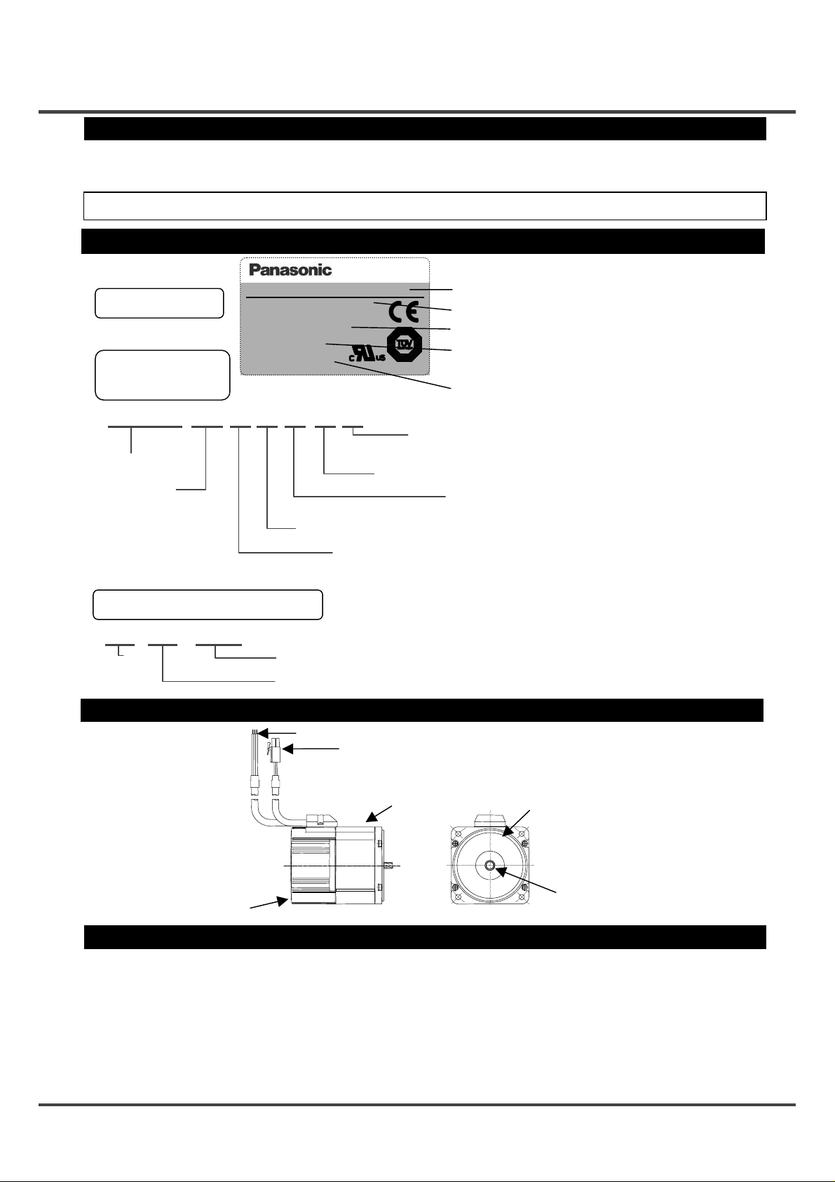
Checking the model of brushless motor
Brushless Motor
Nameplate
Check the
Model Name
MBMC 3A 1 A X A
Series name
Output
3A: 30 W
5A:50 W
9A:90 W
1E:130 W (Rating 30 min)
Check the Serial Number
*
03 11 0001*
Manufacturing
year
(Lower 2 digits of Christian Era)
Name of each part
Model No.
Input
Input Current
Ins. Class
Rated Output
Rated Speed
Rating
Ser. No. 03110001
Matsushita Electric Industrial Co.、Ltd.
MBMC3A1AXA
1Ph.100V-120V
1A
A(UL),E(TUV)
30W
3000r/min
S1
IP65
Made in Japan
C26701
Model name
Rated input voltage
Rated output
S1: Continuous rating,
S2: Short time rating
Set specification
Function A: Standard
Shaft specification
Structure A: Standard
Input power supply
1:
Single phase
Single phase
2:
Serial Number
Manufacturing month
Power input line
Connector for control signal
* Indicates production in November 2003, serial
Serial Number
(Blank): Console A attached
P: Console A attached
X: For gear head MX8G
Z: For gear head MZ9G
S: Round shaft
AC100 – 120 V
AC200 – 240 V
number 0001.
Control circuit unit
Motor unit
Label of safety precaution is affixed to the product.
O-ring (not attached in
specification of round
shaft)
Oil seal
Precaution for proper use
1. This motor incorporates control circuit. Control circuit is sensitive to temperature and impact, therefore read
this instruction manual carefully for proper installation.
2. This motor is controlled by switching the power element at a high speed.
Therefore, when the motor runs, leaking current may increase, which activates the leakage breaker.
In such a case, use a leakage breaker which is provided with measure against high frequency for inverter.
3. In starting and stopping the motor, use the operation instruction input "I1" or RUN/STOP switch of console A
and digital key pad. When the motor is turned on and off by turning on and off power supply, the life of inner
circuit may be shortened.
4
Page 5
Installation
Installation
Install the brushless motor properly for preventing failure and accident.
Transport
● Use caution enough in transporting the unit to prevent injury by drop or fall, and avoid damage to
the equipment.
Storage
● Keep the unit indoors in a clean and dry place free from vibration with little change of tempe rature.
● In keeping a gear head alone, direct the output shaft down.
Location
● Location gives great influence upon the life of brushless motor, therefore choose a place in
conformance with the conditions below:
(1) Indoors where the motor is not subjected to rain water and direct sun beam.
(2) Do not use the motor in corrosive atmosphere such as hydrogen sulfide, sulfurous acid, chlorine, ammonia,
sulfur, gas chloride, gas sulfide, acid, alkali, and salt, in the atmosphere of combustible gas, or in the vicinity of
flammables.
(3) Place not exposed to grinding liquid, oil mist, iron powder, and cutting particle.
(4) Well-ventilated place with little moisture, oil, or inundation, and place far from heat source such as a furnace.
(5) Place easy to check and clean
(6) Place free from vibration
(7) Do not use the unit in an enclosed environment. Enclosing may raise the temperature of motor, and shorten
their life.
(Otherwise, grease leaking is possible.)
Caution in Installing Gear Head
● Idling by damaged tooth, locking by bite, grease leakage, and the like are possible on the life end of gear
head. Install a safety device in order to ensure safety even if such trouble should be found.
• Install a device for preventing drop by damaged teeth on a lifter or the like.
• As for application such as opening and closing of door, install a release device against locking by gear bit ing.
• As for food or textile equipment, install an oil pan for measure against grease leakage.
• Do not install an encoder, sensor, contact, etc in the proximity of gear head. If you should install such devices,
take measures against their grease leakage.
• Be sure to perform daily check in order to prevent unexpected accident.
Environmental condition
Item
Ambient
temperature
Brushless motor
Console A, Digital key pad (optional)
Ambient humidity
Storage temperature
Protection
structure
Brushless motor
Console A, Digital key pad (optional)
-10°C - 40°C (free from freezing)
-10°C - 50°C (free from freezing)
85% RH or below (free from condensation)
-20°C - 60°C (free from freezing)
IP65 (excluding output shaft rotating area, and tip of lead)
x This motor conforms to test condition specified in EN standard (EN60529 and
EN60034-5). This motor is not applicable to the use which requires long-term
waterproof performance, such as the case where the motor is always washed
with water.
Condition
Equivalent to IP20
※1
1
*
2
*
Vibration Not greater than 4.9 m/s2(10 – 60 Hz)
Altitude Not greater than 1000m
*1Ambient temperature is measured at a di st an ce of 5 cm from the motor.
2
Temperature which is acceptable for a short time, such as during transportation.
*
5
Page 6
Installation/System configuration and wiring
Others
● Oil and water protections
(1) Direct down the lead of cable as far as possible.
(2) Avoid use in such an environment where motor is always exposed to oil and water.
(3) Avoid use with cable immersed in oil and water.
● Cable: stress relieving
(1) Make sure that stress is not applied to the lead or connection of cable due to bending or dead weight.
(2) In installation where the motor moves, fix the cable of motor, incorporate the extension cable
connected beyond in the cable carrier to reduce stress by bending as small as possible.
(3) Allow the bending radius of cable as large as possible.
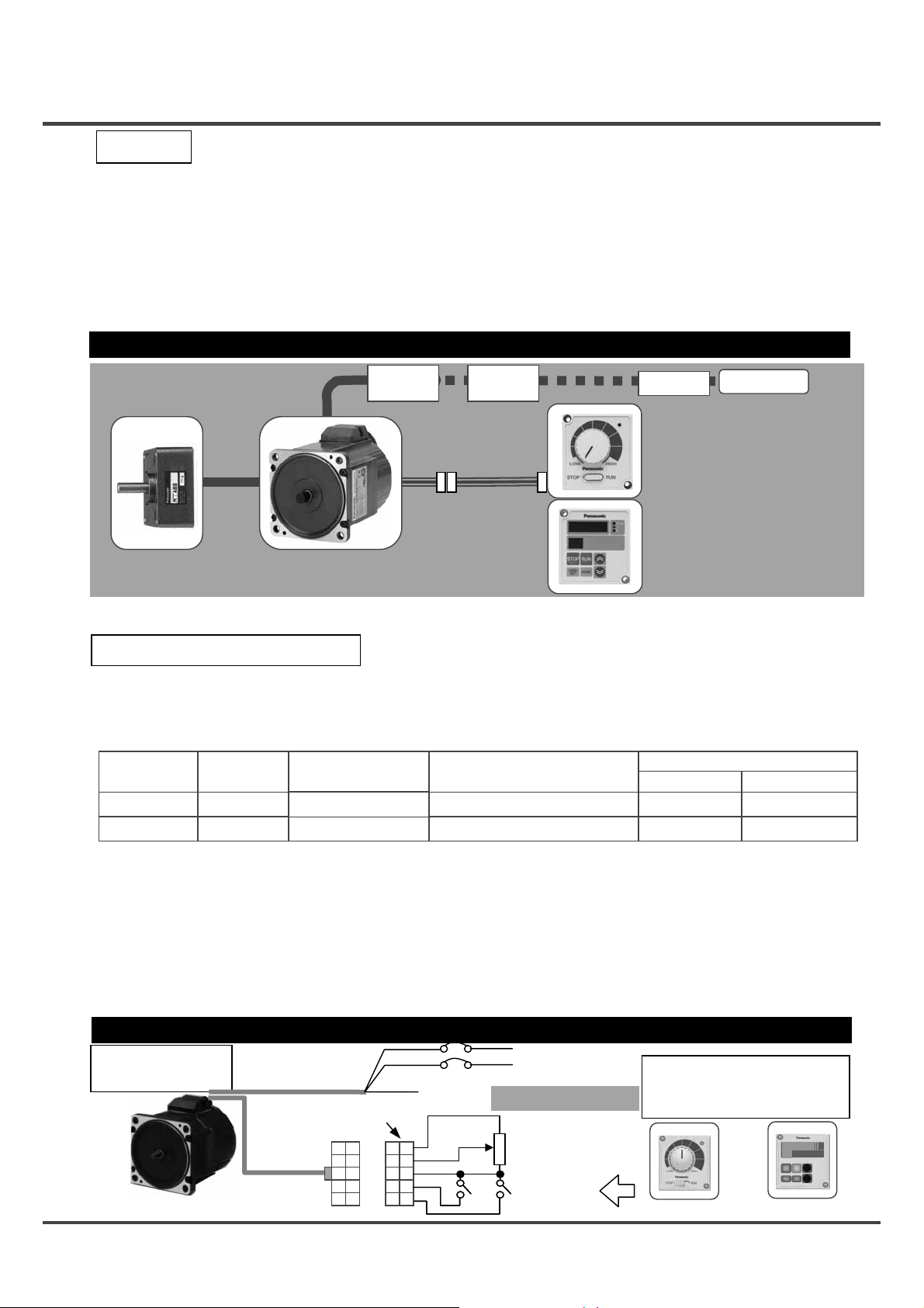
System configuration/general wiring diagram
The lead wire is 0.5m long.
Magnetic
contactor
Noise filter
NFB
AC power
supply
Console A
(attached, optional)
It allows switching
RUN/STOP and CCW/CW
and setting speed.
Digital key pad
(sold separately)
This is a digital display console.
It enables change of parameter.
(See the use of Digital key pad
on page 12 for detail.)
Gear head
(sold separately)
B1 Series
G Type
Extension cable
(sold separately)
Connector kit
(sold separately)
●Wiring work must always be performed by a professional electric worker.
●Do not turn on power before finishing wiring for avoiding electric shock.
Selection of wiring equipment
● Recommended noise filter Option part number: DVOP3611-5
Manufacturer's part number: SUP-EQ5-ER-6
● Selection of non-fuse breaker (NFB), magnetic contactor (made by Matsushita Electric Works, Ltd),
and electric wire (wiring within equipment)
(See "Adaptation to overseas standard" for compatibility with overseas standard.)
Voltage
Single phase 100V
Single phase 200V
Capacity
(w)
30 - 90
30 - 130
NFB (rated current)
BBC25N(5A)
BBC25N(5A)
Magnetic contactor
(contact structure)
BMFT61041N(3P+1a)
BMFT61042N(3P+1a)
Main circuit/
Grounding wire
0.5(AWG20) 0.13(AWG26)
0.5(AWG20) 0.13(AWG26)
■ Be sure to ground the grounding terminal.
In wiring to power supply (outside of equipment) from NFB, use an electric wire of 1.6 mm
diameter (2.0 mm
2
) or more both for main circuit and grounding. Apply grounding class D (100
ohms or below) for grounding.
(Okaya Electric
Industries Co., Ltd)
Electric wire (mm2)
Control circuit
●Selection of relay
As for use for control circuit such as control input terminal, use a relay for small signal (minimum guarantee
current 1 mA or less) for preventing poor contact. <Reference example> Matsushita Electric Works, Ltd: DS
type, NK type, HC type, OMRON: G2A type
● Control Circuit Switch
When using a switch instead of relay, use one for minute current in order to prevent poor contact.
<Example> Nihon Kaiheiki: M-2012J-G
Wiring
Standard
wiring diagram
Nihon Molex
( )
39-01-2105(5557-10R-210)
<Power input line>
(Connector kit A)
<Control
signal connector>
(Motor side)
10
Black
White
Green/
Yellow
5
6
1
NFB (No-fuse breaker)
Grounding
Rotation
speed
5
4
Control gland
3
2
1
Rotation
direction
Power input
Be sure to ground the
grounding terminal.
External speed setting
Variable resistor 5 kΩ
B characteristics 1/4 W or
above
Operation
stop
Do not tighten the ground
wires together, but
connect them individually.
(Console A) (Digital key pad)
6
Page 7
Wiring/Test run
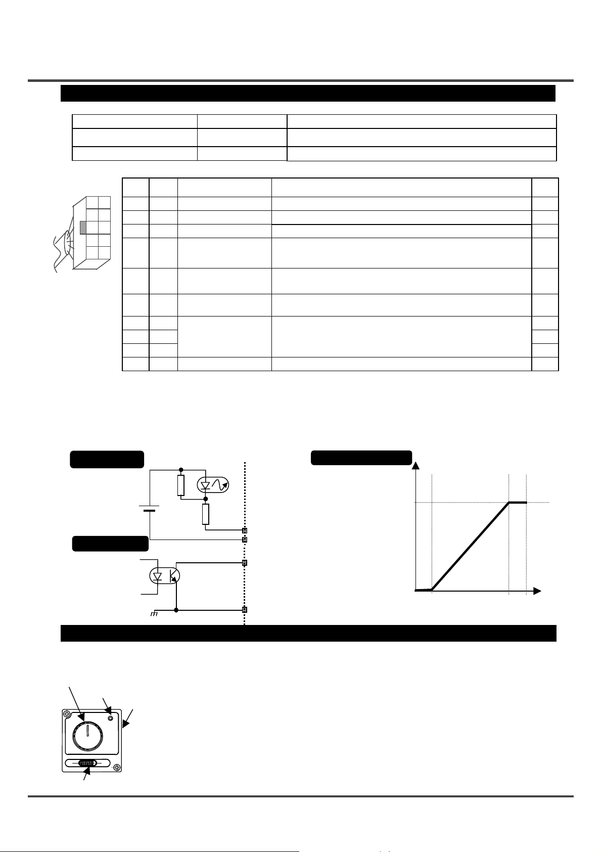
Function of terminal
<Power input line>
Wire color
White/Black (L1, L2)
Green/Yellow (E)
<Control signal connector>
Terminal
10
Terminal
number
1
2
symbol
I1
I2
5
3 GND
4 FIN
6
1
Terminal name Description of function
*1
Operation instruction input
Rotation speed changeover
*1
input
Control ground
Analog speed
command input
Name Description of function
Power input line
Grounding wire
Nihon Molex 39-01-2105(5557-10R-210)
Connect the terminal to commercial power supply conforming to voltage
specification.
Wire for grounding the motor
Motor runs when "I1" and "GND" are shorted, and stops when they are opened.
CW operation when "I2" and "GND" are shorted, and CCW operation
when they are opened.
Common ground terminal for control signal.
Speed can be set by applying voltage DC0 – 5V.
Input impedance 100 kΩ.
*3
*2
Wire
color
Brown
Red
Orange
Yellow
(Motor side)
Input circuit
Internal
power supply
(+5V)
Output circuit
5 +5V
6 O1
External speed setting
power supply
*1
Trip output
Power output dedicated when connecting an external variable resistor
(5 kΩ, B characteristics) to FIN input (Cannot be used for any other purpose.)
Trip signal output. *1"L" in trip (Contact ON)
Open collector Vce max: DC30V, Ic max: 50mA
7 SCK
8 SIN
Digital key pad I/F
Interface for digital key pad
9 SOT
10 (N/A) −
*1Function of input/output can be changed by the Digital key pad. Default is shown.
2
Rotation direction is that on motor shaft. When gear head is incorporated, the rotation direction of motor and that of gear output shaft
*
are reversed for some gear reduction ratio. See the allowable shaft torque table on page 8.
(CW: Rotation clockwise when seen from the motor shaft, CCW: Rotation counterclockwise when see from the motor shaft)
3
When resistor and control GND are disconnected in use of external variable resistor, 5V is input to FIN irrespective of setting of
*
variable resistor, and upper speed limit is directed; therefore use caution enough for connecting GND.
■ See the optional connector kit A (DVOP3600) for compatible connector.
In extending the control signal wire, keep it below 5m long, and use wire rod above AWG26 (0.12mm
Photo-coupler
(Do not connect anything.)
FIN characteristics
Preset speed
2
).
(Typical value)
(r/min)
1.5kΩ
I1, I2
(Upper speed limit)
3000
GND
01
Green
Blue
Purple
(Pink)
Gray
White
Black
V
ce max
cmax
I
GND
Inspection prior to test run (Console A)
・ Connect the
Console A
Speed
potentiometer
Power
lamp
RUN/STOP switch
Rotation
direction
selecting
switch
(Check before operation)
(1) Any mistake found in wiring? (2) Input power supply conforms to rating?
(Test run)
When RUN/STOP switch is changed to RUN, the motor rotates, and when the switch is returned to
STOP, the motor stops.
Rotation direction can be changed by rotation direction selecting switch on the side of console.
When the rotation direction is changed in RUN, the motor is inverted suddenly, and the motor may
trip due to some inertia of load.
Rotation speed can be adjusted by the speed potentiometer.
Turn off power when the motor is to be stopped for a long time.
■ When power is turned off with RUN/STOP switch on RUN side, and power is turned on again,
the motor may start again, which is dangerous. In turning on power, always make sure that
the switch is on STOP side.
■
When a gear head is incorporated, rotation direction of gear head output shaft may be inverted
for some gear reduction ratio. See the table of allowable shaft torque on page 8.
DC30V
50mA
0
(Lower speed limit)
0V 0.5V 4.5V 5V
FIN input voltage
7
Page 8
Checking the load and use condition
Check use condition for eternal use of this product. Some use conditions may possibly lead to heating or
damage to the shaft. Fully check use conditions, and use the motor in a permissible range.
Standard life
Standard life is 5,000 hours for the motor equipped with gear head (MB8G and MB9G). Standard life is the same
10,000 hours for motor alone (round shaft). (Standard life of sealing performance of oil seal is 5,000 hours.)
Standard life refers to design life for operation 8 hours per day (service factor: Sf = 1.0) at a normal temperature and
humidity, under uniform load (permissible shaft torque of gear head and rated torque of motor).
Service factor (Sf)
Service factor (Sf) depends on the magnitude of shock of load or operating time. Service factor is shown below
for different load conditions:
Expected of life =
Example of load Type of load
Uniform load
Light shock
Middle shock
Heavy shock
Permissible shaft torque
Required shaft torque TA of gear head can be obtained from service factor and actual load torque T1.
One direction continuous operation
Start, stop, or cam shock
Instantaneous rotation/reverse rotation and instantaneous stop
Middle shock at a high frequency
TA=T1×Sf
Select a gear head and motor to ensure that required torque (continuous) is within permissible shaft torque in
the table below. Here, the torque T1 must not exceed permissible shaft torque TA irrespective of Sf.
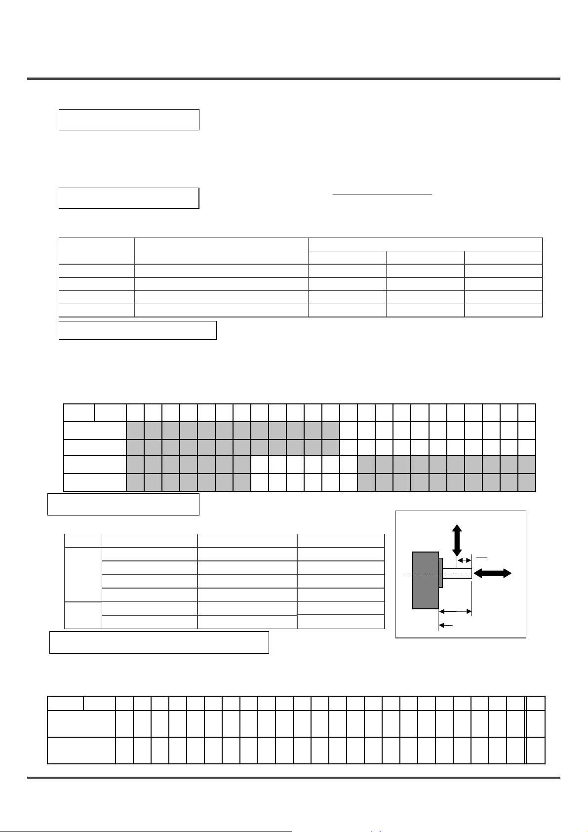
Reduction
Model
name
MBMC3A□AXA
MBMC5A□AXA
MBMC9A□AZA
MBMC1E□AZA
ratio
MX8G□B
MX8G□B
MZ9G□B
MZ9G□B
5
0.38
0.64
1.12
1.69
* Rotation direction is the same as that of motor in shaded portion, and reverse for others.
Permissible shaft load
Use the permissible shaft load within the load shown below:
Permissibleoverhang (w) Permissible thrust (F)
Motor
alone
Gear
head
Model name
MBMC3A□ASA 100N 10N
MBMC5A□ASA 100N 10N
MBMC9A□ASA 150N 20N
MBMC1E2ASA 150N 20N
MX8G type 294N 49N
MZ9G type 588N
Standard life
Service factor (Sf)
Service factor
5 hours/day 8 hours/day 24 hours/day
0.8
1.2
1.5
2.5
1.931.551.391.150.960.770.690.580.460.280.23
2.16
3.61
3.232.592.331.921.611.291.160.960.770.460.39
6.22
9.34
147N
30
1.0
1.5
2.0
3.0
Motor and
gear head
Overhang load
(W)
L
Mounting surface
1.5
2.0
2.5
3.5
Unit: N m
7.847.847.846.996.455.434.363.552.60
7.847.847.847.847.847.847.295.934.33
L
2
Thrust load
(F)
スラスト荷重
20018015012010090756050362520181512.51097.563.63
−
−
19.619.619.619.619.017.314.711.79.816.965.274.113.723.062.542.282.021.691.340.810.67
19.619.619.619.619.619.619.617.514.710.57.916.175.584.593.823.423.042.542.021.211.01
Permissible load inertia moment
Apply permissible load inertia moment within the value shown below:
(Acceptable value on round shaft applies when stopping operation in free-run stop. In speed reduction stop, the value is 1/4 of
indication below only on round shaft due to regeneration. Set a longer speed reduction time if the inertia is not to be lessened. )
name
MX8G□B
MZ9G□B
Reduction
ratio
5
3.42
16.4
Model
MBMC3A□AXA
MBMC5A□AXA
MBMC9A□AZA
MBMC1E□AZA
Set the acceleration/deceleration time 0.3 seconds or longer.
Unit: ×10 kg-4・m
30
127
589
18015012010090756050362520181512.51097.563.63
34234234234234234234234218386.955.845.230.621.613.811.27.724.901.791.25
1684168416841684168416841684168484742325721114298.367.653.437.323.68.475.93
8
200
−
1684
2
Round
shaft
2.5
5.6
Page 9
Maintenance and inspections/Assembling of Gear Head
Assembling of Gear Head
● Preparation before assembling
(1) Compatible gear head described on this instruction manual is MX8G□B (for 30, 50W) and MZ9G□B
(for 90, 130W). Never combine anything other than compatible gear head in use. Failure to observe this
direction may result in malfunction. (□ represents speed reduction ratio.)
(2) Make sure that the O-ring is attached to the bottom of motor flange.
If the gear head is assembled with O-ring floating, it may result in grease leakage.
(3) When grease adheres to the end surface of gear head, wipe off sufficiently.
If the gear head is assembled with grease adhered, it may cause grease to exude.
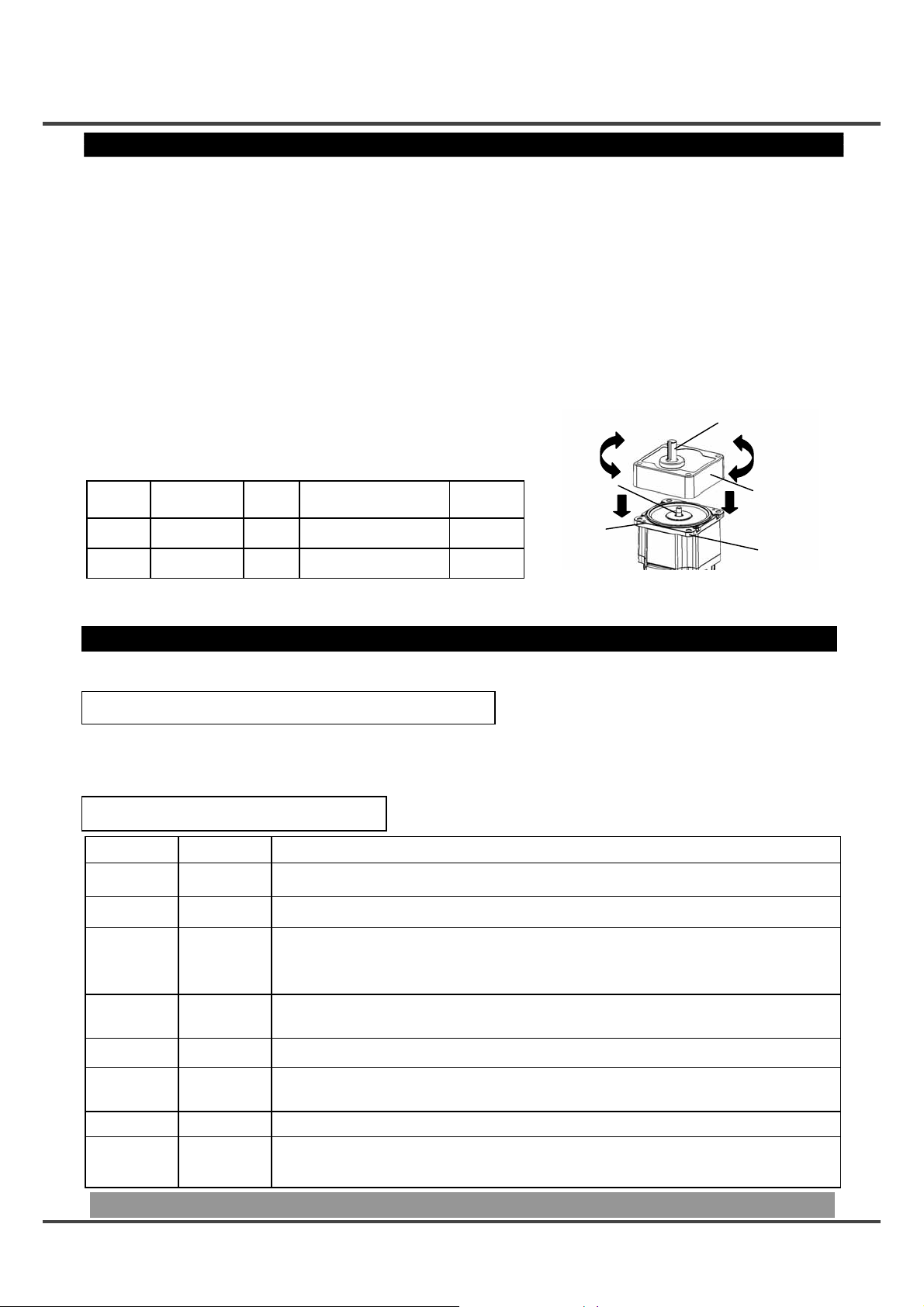
● Assembling
(1) Direct the motor pinion upward, and make sure that the relation between direction of motor lead wire
and output shaft matches with the equipment.
(2) Turn the motor pinion finely clockwise and counterclockwise for assembling, ensuring that the tip of
motor pinion does not hit the tooth of gear head.
(3) In installing the motor and gear head to the mating equipment, use "mounting screws" attached to the
gear head, tighten them sufficiently to eliminate clearance
between the motor flange surface and gear head end
surface while paying attention to bite of O-ring.
Recommended tightening torque is shown below:
Mounting
Angle
dimension
Type of
gear head
Screw
size
Tightening torque
Mounting
pitch
diameter
□80 MX8G M5 2.45N・m 94mm
□90 MZ9G M6 2.94N・m 104mm
Motor
pinion
O-ring
Output shaft
Gear head
Flange
Note) Excessive force to assemble the motor and gear, or damage to the tip of
motor pinion or tooth of gear head may generate abnormal noise or reduce the life.
Maintenance and inspection
Routine maintenance and inspection are essential for proper and satisfactory operation of
the motor.
Notes to Maintenance/Inspection Personnel
● Power-on/off operations should be done by the operators themselves for ensuring safety in checking.
● Do not touch the motor while power on.
● In performing the measuring insulation resistance, remove all connections. Measuring insulation
resistance with connection can cause motor failure.
Maintenance/ Inspection item
Maintenance/
Check item
Input voltage Voltmeter Must be within ±10% of rating.
Input current Ammeter Must be within rated input current described on nameplate.
Insulation
resistance
Noise
Inspection
procedure
Insulation
resistance
tester
Hearing
Condition
Measure the insulation resistance of motor with 500V Megger. It must be above 1Mohm.
Measuring position: Between power input line (L1, L2) and grounding wire
Noise level must not be different from the usual level. In addition, abnormal noise
such as rumbling noise must not be heard.
Vibration By hand Free from abnormal vibration.
Grease
leakage
Installation
bolt
Use
environment
By sight
Torque wrench
By sight
Check that periphery of motor or gear head is not wet by grease or oil. Protect them with
a cover etc. in application which is deteriorated by grease leakage.
Check for loosening of bolt, and tighten additionally as necessary.
Check the ambient temperature and humidity, and make sure that dirt, dust, or foreign
substance is not found.
Make sure that the opening of brushless inverter is free from lint.
Be sure to contact our service division or sales agent for disassembling and repairing of the motor.
9
Page 10
Protective functions/How to clear trip
Protective functions
■ When the protection fu nction is activated, motor stops and trip signal output turns on.
Description of trip can be displayed only when the Digital key pad (option) is connected.
Protection function works even when the Digital key pad is not connected, but it is not displayed.
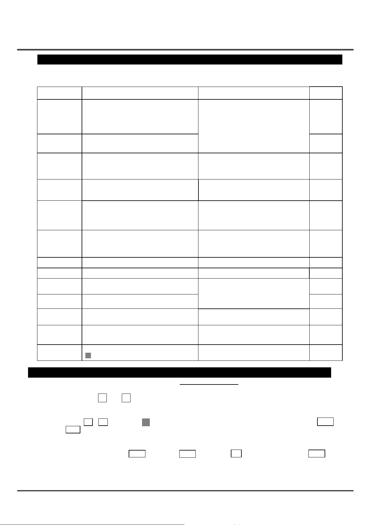
Protective item Description
When the internal DC voltage is below specified value,
operation is stopped; when voltage is recovered, operation
Undervoltage warning
(default)
Undervoltage error
Overload warning
(Electronic thermal)
Overload error
(Electronic thermal
relay)
Overcurrent error
Overvoltage error
User
parameter error
System
parameter error
System error
Sensor error
Overspeed error
Overheat error
Setting change
warning
is started again. (This is not trip, and no trip output is
made.)
■Trip can be set by parameter 50.
100V product: Approx DC100V,
200V product: Approx DC200V
The motor trips when internal DC voltage is below
specified value only if trip is set by parameter 50.
100V product: Approx DC100V,
200V product: Approx DC200V
When load factor exceeds specified value, the electronic
thermal relay operates and monitor display flashes.
It is a warning for electronic thermal trip.
30-90W: 100%
130W : 80%
The motor trips when motor torque is output continuously
above specified value.
30-90W: 115%
130W : 105%
The motor trips when the motor current exceeds specified
current.
The motor trips when internal DC voltage (voltage of
smoothing function of power supply) rises and exceeds
specified value.
Product of 100V: Approx DC200V,
Product of 200V: Approx DC400V
Parameter data saved in EEPROM is abnormal.
Internal parameter data saved in EEPROM is abnorma l. Failure is possible.
The motor trips when trouble of control microcomputer is
detected.
The motor trips when trouble of CS sensor signal is
detected.
The motor trips when rotation speed (actual speed)
exceeds specified value.
Approx 4500r /min
The motor trips when the temperature in control section
rises above specified value.
Approx 105℃
The motor trips when any important parameter such as
" 30 Run command selection" is changed
Investigate the condition of wiring and circumstances of
power supply.
Reduce the load.
Check the load factor in monitor mode.
Investigate the cause of overload, and reduce the load,
change the operating pattern by making acceleration
and deceleration time longer, or apply design to increase
the capacity of motor.
Excessive acceleration/deceleration setting or gain
setting is possible. Set the longer
acceleration/deceleration time and the smaller gain.
If this trip should occur as soon as the unit is started,
failure is possible.
If the motor should trip in running, too short deceleration
time is one of the causes. Adjust deceleration time. No
measure can be taken in continuous regenerative
operation such as lowering.
Check all parameters again and set them again. If this
protection works frequently, failure is possible
①Malfunction due to external noise is possible.
Investigate for noise source in the vicinity and
eliminate such source.
②Internal circuit may be in failure.
Ensure that the actual speed does not exceed rated
rotation speed, such as overshooting by unmatching
between load and gain.
Check the ambient temperature and cooling condition of motor.
Check the load factor.
If the ambient temperature is low enough, and the protection
occurs soon after power-on, failure is possible.
This is not abnormal. Trip reset in order to make change
effective.
Measure
Display on
Digital key pad
L
E-LV
5-digit LED
flashes.
THr
E-OC
E-OV
E-UPr
E-SPr
Err
E-CS
E-OS
E-OH
CAU
How to clear trip
If the motor should trip, eliminate the cause and use any of the procedures [1] – [3] below for clear.
[1] Turn off power, and when power LED has gone out, turn on po wer again.
[2] Press the switch and of the Digital key pad simultaneously for one second or more with present trip
>>
>>
state displayed.
[3] Input the trip reset signal.
(When F-r or r-F is chosen in " 33 I1/I2 function selection", enter "I1" and "I2" at the same time; when F-rST or
r-rST is chosen, enter "I2" for trip reset.
Trip reset signal, when continued to be input, is designed to become ineffective in order to prevent inadvertent
restarting. Enter trip reset signal only when necessary.)
Note: As for overcurrent error E-OC , sensor error E-CS , System error Err , and user parameter error E-Upr , reset
them by turning off power as shown in [1] above. No other procedure is effective.
(Caution) In clear trip, be sure to find and remove the trip factor before clear.
10
Page 11

Troubleshooting
If any trouble should be found, follow the steps below for check and countermeasure.
● If the cause cannot be found, it is recommended to use the Digital key pad and check
the detail of trip. If failure is likely, or when any part is damaged, or when you are in any
other trouble, contact the sales agent of purchase or our company.
Phenomenon Detail of checking Measure, etc
Check for abnormality of wiring. Apply proper wiring.
Motor does not
rotate.
Motor does not
rotate or stops
during operation.
Motor stops during
deceleration.
Motor does not
stop quickly when
stop command is
input.
Check whether protective function is
activated.
(Only when the motor is connected to the
key pad )
Check whether 7-segment LED of on the
key pad is lighted up.
Check whether voltage on input power is
normal.
Check whether operation start signal is
input.
Check whether Analogue speed
instruction is set at 0V.
Check whether protective function is
activated.
Check whether the inertia of load is too
large.
The motor with large inertia does not stop
quickly because default stop mode is
Free-run stop.
Check the detail of trip by the Digital key pad.
Turn off power once, and turn on again.
If the LED is off when power is input to the motor,
failure is possible.
Contact us for repair.
Check the supply voltage.
Check the condition of operation instruction.
Raise the analogue speed instruction little by little.
Overload is possible. Reduce the load or increase
the output capacity.
Regenerative voltage protection may have
worked. Decrease the inertia. Turn off power
once, and turn on again, and reset the trip state.
Make deceleration time longer by the Digital key
pad. Alternatively, apply free-run stop.
Stop motor by 0V analogue speed command.
Change stop mode to deceleration stop by Digital
key pad .
Large vibration or
noise.
Motor rotates
reversely.
Rotation speed is unstable
during operation
(actual speed).
Parameter dose
not change.
Output shaft of motor (gear head) and shaft
of load are not aligned.
Motor and gear head are not assembled
correctly.
Damage to gear head or bearing. Contact us for repair.
Check whether Setting of rotation
direction changeover input is wrong.
Rotation direction of the motor and gear
output shaft may be reversed for some
gear reduction ratio of gear head.
Check whether the load fluctuates greatly.
Check whether operation start signal is
input.
Check the joint between the output shaft and load
shaft of the motor (gear head).
Check the assembling condition between motor
and gear head, and their combination, and
assemble them properly.
Check the position of rotation direction choosing
switch for the console A. As for others, check the
status of "I2".
Check the gear ratio and rotation direction. See
the list of permissible shaft torque on page 8.
Reduce the fluctuation of load. Increase the
output capacity.
Some parameters cannot be changed when
operation instruction is on. (See the check
column of parameter list on page 18.)
Turn off operation instruction before changing.
11
Page 12

How to use Digital key pad
Name of each part and Installation
●What can be done by Digital key pad
x Monitoring of rotation speed (actual speed) and load factor, etc
(Rotation speed can be displayed being multiplied by the factor set by parameter 47 and 48 .)
x Display detail of trip, and trip history. Trip reset by pressing and .
x Parameter setting, initialization, and copying function at the same time.
x Start and stop of motor by RUN / STOP switch
required.)
■ When using the digital key pad and control signal input at the same time, buy an optional control signal branch
cable (DVOP37505).
(Setting of parameter " 30 Run command selection" is
●Name of each part
>>
>>
5-digit LED
2-digit LED
MODE switch
DATA
switch
SET
>>
>>
switch
RUN switch
STOP switch
2-digit LED
STOP switch
DATA
SET
RUN
switch
switch
5-digit
>>
switch
>>
switch
MODE
LED
switch
Displays rotation speed (actual speed), commanded speed, trip history, setting of parameter,
and the like.
Displays the number of parameter (in editing parameter).
Displays the rotation direction in operation. Displays 00 when the motor is stopped.
(CCW as viewed from the output shaft of motor … F and CW … r )
Rotation direction of gear head output shaft may be reversed for some gear reduction
ratio when gear head is incorporated. See the table of acceptable shaft torqu e o n
page 8.
Switch for changing monitor mode. Whenever this switch is pressed, the mode changes in
this sequence: Rotation speed (actual speed) Æ Internal DC voltage (voltage of smoothing
capacitor of power supply) Æ Load factor Æ Torque Æ Comm anded speed Æ Rotation
speed (actual speed) Æ …. *
* When you press this switch in the parameter setting mode, setting is stored.
This is a switch for changing between parameter number mode and parameter setting mode,
and for storing parameter setting.
This switch enables selection of parameter, and setting and changing of contents.
When the motor is tripped, pressing and at the same time enables clear of trip.
>>
>>
This switch is for instruction of operation. (Only when " 30 Operation instruction selection" is
PnL )
■See " 33 Choosing I1/I2 function" (2) on page 23 for rotation direction.
This switch is for instruction of stopping. (Only when " 30 Choosing operation instruction" is
PnL )
●Description
Displays rotation speed (actual speed), command speed, internal DC voltage, load factor,
and torque on 5-digit LED. When power is turned on, this mode is set.
Monitor mode
This mode is set when power is turned on.
Control changes to this mode when MODE switch is pressed in parameter number mode,
parameter setting mode.
Parameter
number mode
Parameter setting
mode
Displays a parameter number (00 – F0) in flashing.
Control changes to this mode when switch is pressed in parameter number mode.
Parameter number can be changed and selected by and switch.
Displays the detail of parameter (setting) in flashing.
Control changes to this mode when switch is pressed in monitor mode.
Change setting by and switch.
DATA
When switch is pressed after change of setting, it is saved in EEPROM.
SET
>>
>>
DATA
SET
DATA
SET
>>
>>
* Displays rotation speed r/min in norma l monitor mode. Displays torque a nd load factor assuming the
rated motor torque at 100%.
* Display is just a guide. Do not use the Digital key pad for a measuring instrument.
12
Page 13

Operating Instruction
Turn on
power.
Only
" 00 "
>
>
Storage
>
>
Press
MODE
Monitor mode
Press
MODE
Parameter
number
mode
Press
DATA
SET
Storage
Press
DATA
SET
Press
DATA
SET
●Press
MODE
Rotation
speed
MODE
Internal DC
voltage
MODE
Load factor
switch for changing display.
●
r/min
○
○
Internal speed (0-th speed)
○
○
●
V
Flashing
○
●
%
○
MODE
can be directly set by and
in monitor mode.
0
>
>
Flashing
00
MODE
○
Torque
MODE
Speed
setting
●
%
○
Flashing
●
r/min
○
○
●2-digit LED blinks and allows selection of parameter number.
0.30
10
Flashing
00
0
Flashing
>
>
>
>
Change (select) a parameter number
by or .
>
>
>
>
>
>
>
>
>
>
>
>
>
>
●5-digit LED blinks and allows change of parameter value.
Parameter
setting mode
0.30
10
>
When switch or MODE switch is
DATA
SET
pressed in parameter setting mode, data is
stored.
>
>
>
● When or is pressed in monitor mode, detail of " 00 Internal speed (0-th speed)" is
>
displayed in blinking, and speed setting can be changed by and . When 31 Speed
command selection is PnL , the motor speed also changes following the speed setting if the
motor is running.
Data is stored only when switch is pressed. Note that data returns to settings when power is
DATA
SET
turned off.
>
Change (select) a parameter value by
>
>
>
>
Flashing
>
>
or .
0.31
10
>
>
>
>
>
>
>
>
Flashing
13
Page 14

Test run (Digital key pad)
Inspection prior to test run
(Inspection prior to test run)
(1) Make sure that all wiring is correct. (2) Make sure that input power supply conforms to rating.
(Test run)
Test run procedure by the Digital key pad is as follows:
An example is introduced here where the motor runs CW at 1800r/min with the Digital key pad.
(1)Be sure to first perform the work below for safety.
Separate the motor from machine or equipment, and make sure that the motor alone can be
operated.
(2)Then turn on power and follow the step below for test run.
Description of
operation
[1] Turn on
power
[2] Change of
initial setting
(Change the choice
of operation
instruction from I1/I2
TEr to the Digital
key pad PnL)
[3] Trip reset
Switch LED display
Press
Press several
DATA
SET
>
>
times to choose
parameter number 30 .
Press
Press to change
DATA
SET
>
>
parameter value.
Store by .
Setting change warning is
issued because setting of
operation instruction has
been changed.
Press and at
DATA
>
>
SET
>
>
the same time.
Digital key pad
●
0
○
○
00
○
0
00
TEr
○
○
Flashing
○
○
○
30
CAU
○
CAU
○
○
Flashing
30
PnL
30
0
00
TEr
●
○
○
○
○
○
Flashing
○
○
○
Flashing
[4] Change of
(Change the choice
of speed instruction
from analogue
speed instruction
input to " 00 Speed
setting (the 0-th
speed)" to enable
use of Digital key
pad.)
[5] Trip reset
14
initial setting 2
DATA
Press
Press several
SET
>
>
times to choose
parameter number 31 .
Press
Press to change
DATA
SET
>
>
parameter value.
>
>
DATA
SET
>
>
Store by .
Setting change warning is
issued because setting of
operation instruction has
been changed.
Press and at
the same time.
0
00
Flashing
VoL−A
31
30
CAU
CAU.
CAU
○
○
○
VoL−A
31
○
○
○
Flashing Flashing
PnL
○
○
○
Flashing
○
○
○
31
30
○
○
○
0
●
○
○
00
Page 15

Description of
operation
[6] Choosing
rotation
direction*
(This operation is
not required for
rotation forward
[CCW].)
[7] Trip reset
Switch LED display
DATA
Press
Press several
SET
>
>
times to choose
parameter number 33 .
Press
Press to change
DATA
SET
>
>
parameter value.
>
>
DATA
SET
>
>
Store by .
Setting change warning is
issued because setting of
operation instruction has
been changed.
Press and at
the same time.
Digital key pad
0
00
Flashing Flashing
rS.Fr
33
30
CAU
CAU.
CAU
○
○
○
○
○
○
○
○
○
Flashing
rS.Fr
33
r−F
33
30
0
00
○
○
○
○
○
○
●
○
○
Flashing
[8] Speed setting
Press
>
>
○
○
0
○
Flashing
x Internal speed (0-th speed) is
displayed (setting at 0r/min).
00
○
>
Press to set a speed.
>
1800
○
○
Flashing
x Set the Internal speed (0-th sp eed)
at 1800 r/min.
00
●
○
r
0
0
○
x Data is still stored if power is cut off
here.
●
○
○
x Displa y of rotation spe ed changes
little by little toward 1800 r/min
x Displa y of rotation direction *
(r indicates that the motor is rotating
CW.)
●
○
○
x Displa y of rotation spe ed changes
little by little toward 0 r/min.
[9] Reset to
monitor mode.
Press MODE
00
[10] Operation
instruction
[11] Stop
instruction
Press RUN
Press STOP
1800
00
[12] Power OFF
<Checkpoint in Test run>
(1) Check whether the motor rotates smoothly. Check for abnormal noise and vibration.
(2) Check whether the motor is accelerated and decelerated smoothly.
(3) Rotation direction and rotation speed of the motor are matched?
* Rotation direction of gear head output shaft may sometimes be reversed due to reduction gear ratio when
gear head is installed.
(See the list of permissible shaft torque on the page 8)
* Rotation direction can also be changed by use of "I2". See " 33 I1/I2 function selection " (2) on page 23.
■ Setting is still stored when power is turned off. When operating the motor with Digital key pad only in trial
run, either reset the setting or initialize parameters after completion of trial run. (Parameter 54)
Here, note that all parameters return to default when parameters are initialized.
15
Page 16

How to copy parameter
1. Reading a parameter value from motor to the Digital key pad
■Once parameters are read into the console, their details are stored in the Digital key pad.
Description of
operation
[1] Turn on
power.
[2] Call 57
Parameter
Copy.
[3] P.LOAd
Choose reading
a parameter into
the Digital key
pad.
[4] Read a
parameter
into the
Digital key
pad.
[5] Wait about 30
seconds.
[6]
Reading of
parameter into
the Digital key
pad completed
Switch LED display
DATA
Press
Hold down to
SET
>
>
choose parameter
number 57 .
DATA
Press
Press twice to
SET
>
>
choose P.LOAd .
DATA
Press for 1 second
SET
while holding down
STOP .
Press STOP
Digital key pad
0
00
Parameter
value
00
Flashing
n0
Flashing
57
P.LOAd
57
P.End
0
00
●
○
○
●
○
○
○
○
○
○
○
Flashing Æ Slow flashing
○
(once per second)
○
○
○
●
○
○
n0
57
P. LOAd
57
○
○
○
Flashing
○
○
○
Flashing
16
2.
Copy a parameter value saved in the Digital key pad onto th e m ot o r.
Description of
operation
Switch LED display
Digital key pad
Turn on power. Call out 57 Parameter. (Same operation as 1. [1] and [2])
[1] P.PrOG
Choose writing
a parameter to
the motor.
[2] Write a
parameter to
the motor.
[3] Wait about 10
Press twice.
Press three times to
choose P.PrOG .
Press for 1
second while holding
down STOP .
DATA
SET
>
>
DATA
SET
n0
57
P.PrOG
57
P.End
○
○
○
Flashing
○
○
Flashing Æ Slow flashing
○
(once per second)
○
○
○
seconds.
P.PrOG
Flashing
57
○
○
○
Page 17

Description of
operation
[4]
Completion of
writing a
parameter from
the Digital key
pad to the motor
Digital key pad
Switch LED display
○
CAU
○
○
[5] Reset to
monitor mode.
>
Press and at
>
>
>
the same time for
clear trip.
0
00
●
○
○
Error while copying a parameter
P.Err1 : Data is abnormal while copying.
ÆPress STOP switch for clearing, and then copy data again. If data is still abnormal, initialize
the Digital key pad and retry.
P.Err2: Copy error
Æ This error occurs in an attempt to copy data between products of different function. Press
STOP switch for clear.
Parameters can be copied between the same models (B1-G Series standard unit), but
parameters should be copied between the same output in principle because gain setting is
different.
3. Initializing of data of Digital key pad
■ When any trouble occurs during copying, it can be often solved by initializing the Digital key pad.
(Stored data is cleared by initializing.)
Description of
operation
Switch LED display
Digital key pad
Turn on power and call 57 Parameter. (Same operation as 1. [1] and [2])
[1] P.InIT
Press
Choose
initialization of
data of Digital
key pad.
[2] Initialization
of Digital key
pad
Press once and
choose P.InIT .
Press for 1
second while holding
down STOP.
[3] Wait about 30
seconds.
[4]
Initializing of
data of Digital
key pad
completed
■ Do not turn off power or disconnect the cable of Digital key pad during operation such as "Reading a
parameter from the motor to the Digital key pad", "Copying a parameter value stored in the Digital key pad
to the motor", and "Initializing the data of Digital key pad".
Press STOP
DATA
SET
DATA
SET
○
>
>
n0
57
P.InIT
57
P.End
0
○
○
Flashing
○
Flashing Æ Continuous lighting
○
○
LED display changes from flashing to continuous
lighting during initializing operation.
○
○
○
●
○
○
P.InIT
57
○
○
○
Flashing
00
17
Page 18

Parameters
Overview of parameter
Motor of this series is provided with various parameters for adjusting and controlling its characteristics and
function. Purpose and function of respective parameter are described. Understand them well enough and adjust
the unit at your optimum operation condition.
List of parameter composition and setting
Parameter
No.
00
10
12
14
15
16
17
1A
1b
30
31
Name of parameter
Internal speed (0-th speed)
1st
acceleration time
1st
deceleration time
Acceleration mode
selection
Deceleration mode
selection
Stop mode
selection
Free-run waiting time
Velocity loop
proportional gain
Velocity loop
integration gain
Run command
selection
Speed command
selection
Parameter setting
Setting range Minimum unit Default
0 – " 3b Upper speed limit"
- 3 sec : Incremented by 0.01 sec.
0.01 3 - 30 sec : Incremented by 0.1 sec.
- 3600 sec. 30 - 3600 sec : Incremented by 1 sec.
- 3 sec : Incremented by 0.01 sec.
0.01 3 - 30 sec : Incremented by 0.1 sec.
- 3600 sec. 30 - 3600 sec : Incremented by 1 sec.
LIn
S−1
S−2
FrEE
dEC
PnL
TEr
PnL
VoL−A
Linear
S shape-1
S shape-2
Free-run stop
Speed reduction stop
0.0 - 10.0 sec
0 - 10000
0 - 10000
RUN STOP
I1/I2
" 00 Internal speed (0-th speed)"
FIN
and of Digital key pad
*3
*4
1 r/min
0.1 sec
1
1
0
0.30
0.30
LIn
LIn
FrEE
1.0
400(800)
500(1000)
TEr
VoL−A
*2
*2
Check *
C
C
1
F−r
r−F
33
3A
3b
3C
*1When parameter marked with C in the check column is changed and stored, the unit is tripped for safety. It
2
*
3
*
4
*
I1/I2 function
selection
Lower speed limit
Upper speed limit
Torque limit
is not allowed to change them while the motor is running.
Parameter in ( ) is the default of 90W and 130W.
Corresponds to RUN/STOP switch of the console A or signal input.
Corresponds to the speed potentiometer or analogue speed instruction of the console A.
rS.Fr
F−rST
r−rST
0 – " 3b Upper speed limit "
I1: CCW run/stop
I2: CW run/stop
I1: CW run/stop
I2: CCW run/stop
I1: run/stop
I2: CW /CCW direction
I1: CCW run/stop
I2:Trip reset
I1: CW run/stop
I2:Trip reset
0 - 3000 r/min
50 - 150
1 r/min
1 r/min
1%
rS.Fr
0
3000
150
18
C
C
C
Page 19

Parameter
Name of parameter
No.
40
42
44
45
46
47
48
4A
4b
4C
4d
4E
4F
50
51
52
54
O1 function
O1 output polarity
Speed matching range
Output pulse count
Monitor mode
Numerator of display
magnification factor
Denominator of disp la y
magnification factor
Trip history clear
Trip history 1
Trip history 2
Trip history 3
Trip history 4
Trip history 5
Undervoltage
trip selection
Retrial selection , 1 - 4
Retrial start time
Parameter
initializing
selection
selection
selection
selection
Setting range Minimum unit Default
TrIP
STbL
rUn
FrEE
Ck−L
POUT
nOr
rEV
20 – " 3b Upper speed limit"
O.−r
O.−L
AV.−L
S.−r
dC−V
1 ‒ " 48 Denominator of display
nO
YES
nO
YES
nO
nO
YES
Trip
Arriving
Running
Free-run
CCW run
F
CW run
r
Overload detection
Speed pulse signal
Normal polarity
Reverse polarity
1, 2, 3, 4, 6, 8, 12, 24
Rotation speed (Actual speed)
Torque
Load factor
Command speed
Internal DC voltage
magnification factor" x 10
1 - 1000
No operation
Clear trip history
No trip
Trip
1 - 120 sec
No operation
Initialize to default
Parameter setting
TrIP
nOr
1 r/min
1 time
1 time
-
1 sec
50
24
O.−r
1
1
nO
-
-
-
-
nO
nO
5
nO
Check *
C
C
1
57
F0
Parameter copy
For manufacturer use
function
nO
P.InIT
P.LOAd
P.PrOG
No copying of parameter
Initializing the data of Digital key pad
Reading a parameter to the Digital key pad
Writing a parameter to the motor
-
nO
-
19
Page 20

LED display
LED display
Figures displayed on the 7 segment display of the Digital key pad are shown below:
Alphanumeric
LED display LED display
*
Alphanumeric
20
Example of LED display
Example)
Description in the text
Display on Digital key pad
* LED display of "0" is available in two types.
Example)
Description in the text
Display on Digital key pad
Page 21

Detail of parameter
時間
Parameter
Name of parameter Description
No.
Internal speed
00
10
acceleration time
12
deceleration time
Acceleration mode
14
Deceleration mode
15
16
(0-th speed)
1st
1st
selection
selection
Stop mode
selection
Desired running speed can be set. T his is effective when " 31 Speed instruction selection" is
PnL
(PANEL).
Upper limit is limited by " 3b Upper speed limit".
The change factor of output speed in acceleration can be determined.
x Set by time for changi ng 1000r/min.
When it is 0.3 sec (default), time taken for accelerating from 0 to 3000 r/min is 0.9 sec.
x T ime can be incremented by 0.01 sec for below 3 sec, by 0.1 sec from 3 sec up to 30 sec
exclusive, and by 1 sec from 30 sec upward.
The change factor of output speed in deceleration can be determined.
x Set by time for changi ng 1000r/min.
When it is 0.3 sec (default), time taken for decelerating from 0 to 3000 r/min is 0.9 sec.
x T ime can be incremented by 0.01 sec for below 3 sec, by 0.1 sec from 3 sec up to 30 sec
exclusive, and by 1 sec from 30 sec upward.
Straight line acceleration/deceleration and curve (S-shape) acceleration and decel eration can be
chosen individually for acceleration and deceleration.
LIn
LINEAR “S”SHAPE-1 “S”SHAPE-2
回転速度
Rotation speed
0
Straight line up to speed setting.
Standard mode for accelerating and
decelerating.
Time
時間
S−1
回転速度
Rotation speed
0
Relaxes the speed change in
start and end of acceleration and
deceleration.
Time
時間
S−2
回転速度
Rotation speed
0
Curve is emphasized more than
S shape-1.
Time
You can select how to stop the motor.
FrEE
(FREE)
Power supply to the motor is cut off and the motor is stopped naturally when stop command is
input (free-run stop). It takes longer for the motor to completely stop when load inertia is big.
dEC
(DECEL)
When stop command is input, the motor reduces its speed according to preset deceleration time,
Electric-brake is performed by Zero-speed control, and then power is cut off to the motor after
elapse of time set by " 17 Free-run waiting time", and the motor is set in free-run state.
<Example or running pattern in deceleration stop>
■ The motor is servo-locked in
Zero-speed control.
(Electrically controlled so that
motor speed is Zero)
Run command
Speed setting
Motor speed
off
Deceleration by preset
change factor of deceleration
time
Time set by " 17 Free-run waiting time"
17
1A
1b
30
waiting time
Velocity loop
proportional gain
Velocity loop
integration gain
Run command
selection
Free-run
Free-run
Deceleration running
When " 16 Stop mode selection" is set to (DECEL) deceleration stop, servo lock
dEC
Zero-speed control
time(Zero-speed control)after deceleration can be adjusted.
(Free-run state is set after that.)
Enables setting of proportional gain of velocity amplifier. It need not be changed normally.
When this value is made greater, gain is increased, which improves responsiveness of the motor.
When this value is made too large, operation is vibratory.
Setting range: 0 – 10000, Setting resolution: 1
Enables setting of integration gain of velocity amplifier. It need not be changed normally.
When this value is made greater, gain is increased, which improves rigidity of the motor (strength
of servo lock). When this value is made too large, overshooting becomes greater, and the motor
is vibratory.
Setting range: 0 – 10000, Setting resolution: 1
Run Command can be chosen from the following:
PnL
(PANEL) : command the motor to stop with switch of Digital key
pad. The motor cannot be operated by signal input "I1" and "I2".
RUN STOP
Signal input is effective only in setting rotation direction, etc.
TEr
(TERMINAL) : Only the input terminal "I1" and "I2" are effective.
See " 33 I1/I2 function selection".
(Corresponds to RUN/STOP, rotation direction selection switch of Console-A.)
21
Page 22

Detail of parameter
Parameter
No.
31
Name of parameter Description
You can choose whether to use " 00 Internal speed (0-th speed)" or analog input terminal
Speed command
selection
"FIN" for speed command.
PnL
VoL−A
(1) For setting "I1" or "I2" function
State of I1 and I2
I1
OFF
ON
OFF
r−F
State of I1 and I2
(PANEL) " 00 Internal speed (0-th speed)"
(VOL-A) Analog input terminal "FIN" (voltage instruction DC 0-5V)
(Corresponds to speed potentiometer of Console-A.)
F−r
(FORWARD-REVERSE)
I2
OFF
OFF
ON
ONON
(REVERSE - FORWARD)
Deceleration stop when " 16 Stop mode selection" is
Trip reset (which must be retained 0.2 sec or longer) *
I1 I2
Action
Stop
dEC
CCW run
CW run
Free-run stop
Action
33
I1/I2 function
selection
OFF
ON
OFF
rS.Fr
State of I1 and I2
I1 I2
OFF
ON
OFF
F−rST
State of I1 and I2
I1 I2
OFF
OFF
ON
ONON
(RUNSTOP. FORWARD-REVERSE)
OFF
OFF
ON
ONON
(FORWARD-TRIP RESET)
Deceleration stop when " 16 Stop mode selection" is
Free-run stop
Trip reset (which must be retained 0.2 sec or longer) *
Deceleration stop when " 16 Stop mode selection" is
Deceleration stop when " 16 Stop mode selection" is
Stop
dEC
CW run
CCW run
Action
Stop
dEC
CCW run
Stop
dEC
CW run
Action
* Effective only when trip occurs
22
OFF
ON
−
−
−
ON
Stop
Deceleration stop when " 16 Stop mode selection" is
CCW run
Trip reset (which must be retained 0.2 sec or longer) *
dEC
Page 23

Parameter
No.
Name of parameter Description
r−rST
State of I1 and I2
(REVERSE-TRIP RESET)
I1 I2
Action
33
I1/I2 function
Selection
(continued)
OFF
ON
−
(2) When " 30 Run command selection" is (PANEL), the motor can be
commanded with switch of Digital key pad.
Rotation direction in this case can be set by parameter and "I1""I2" state.
When only the digital key pad is connected, "I1" and "I2" are set to OFF .
F−r
State of I1 and I2
−
−
ON
(FORWARD-REVERSE)
Deceleration stop when " 16 Stop mode selection" is
Trip reset (which must be retained 0.2 sec or longer) *
RUN STOP
I1 I2
−
OFF
r−F
State of I1 and I2
OFF
ON
ONON
(REVERSE-FORWARD)
Free-run stop irrespective of switch
Trip reset (which must be retained 0.2 sec or longer)*
CCW rotation selection
CW rotation selection
I1 I2
−
OFF
OFF
ON
ONON
Free-run stop irrespective of switch
Trip reset (which must be retained 0.2 sec or longer)*
CW rotation selection
CCW rotation selection
Stop
dEC
CW run
PnL
Action
RUN
Action
RUN
* Effective only when trip occurs
rS.Fr
State of I1 and I2
(RUNSTOP. FORWARD-REVERSE)
I1 I2
−
−
F−rST
CCW run with switch
State of I1 and I2
OFF
ON
(FORWARD-TRIP RESET)
RUN
I1 I2
−
r−rST
CW run with switch
State of I1 and I2
ON
(REVERSE-TRIP RESET)
RUN
I1 I2
−
ON
Action
CCW rotation selection
CW rotation selection
Action
Trip reset(which must be retained 0.2 sec or longer) *
Action
Trip reset(which must be retained 0.2 sec or longer) *
23
Page 24

Detail of parameter
Parameter
No.
3A
3b
3C
40
Name of parameter Description
When " 31 Speed command selection" is
Lower speed limit
analogue speed instruction
(VOL-A), motor setting speed at 0V input is
VoL−A
set.
Upper limit of motor command speed.
Upper speed limit
When " 31 Speed command selection" is analogue speed command
(VOL-A), motor setting speed at 5V input is set. Further, upper limit of " 00 Internal speed
(0-th speed)" is limited by this parameter.
Upper limit of motor output torque is set.
Torque limit
(No precision is provided because torque is not controlled. Use as a guide.)
100% indicates the rated torque.
Output terminal " 01 " can also be selected as follows.
Polarity of " 40 O1 function selection " can be inverted by " 42 O1 output polarity selection".
TrIP
STbL
(TRIP) : Trip signal (Trip: ON)
(STABLE) : Arriving signal (When reached to a command value ON)
Æ See " 44 Speed matching range".
O1 function
selection
rUn
FrEE
Ck−L
(RUN) : Run/Stop signal (When running: ON)
(FREE) : F ree-run signal (During free run: ON)
(FORWARD) : CCW run signal (During CCW run: ON)
F
(REVERSE) : CW run signal (During CW run: ON)
r
(CHECK−L) : Overload detection
Output when load exceeds 100%
(Load exceeds 100%:ON)
POUT
(PULSE-OUT): Speed pulse signal
Æ See " 45 Output pulse count selection".
Speed instruction value
Upper speed
limit
Lower speed
limit
0.5 4.5
0
Input voltage
5V
VoL−A
O1 output polarity
42
Speed matching
44
45
46
Output pulse
count selection
Monitor mode
selection
range
selection
This is a function for inverting the polarity of signal output between output terminal "O1"
and "GND".
nOr
nOr
rEV
rEV
When " 40 O1 function selection " is set to (STABLE) Arriving signal,
(NORMAL) : Transistor "ON" when activated
(REVERSE) : Transistor "OFF" when activated
STbL
" Speed matching range " for output arrivi ng signal can be adjusted.
x When difference between actual rotation speed and speed setting is smaller than
"Speed matching range", arriving signal is output.
x Even if the speed is reached, when speed matching range is set too small, arriving
signal may turn on and off due to speed fluctuation.
x Arriving signa l is not output when CCW/CW changes.
When " 40 O1 function selection " is set to (PULSE-OUT), pulse count is
POUT
set to be output to " O1" while the motor makes one turn.
(To be selected from 1, 2, 3, 4, 6, 8, 12, and 24)
T
500±100μs
(Ex) When rotation number is 3000 r/min, in the
case where
"
45 Output pulse selection" is 24,
T = =0.83ms
Frequency f = 1/T = 1.2kHz
60
3000×24
You can choose description to be displayed on 5-digit LED when turning on power.
O.−r
O.−L
AV.−L
S.−r
dC−V
(OUTPUT-REVOLUTION) : Rotation speed
(OUTPUT-LOAD) : Torque
(AVERAGE-LOAD) : Load factor (average torque)
(SETTING-REVOLUTION) : Speed command
(DC-VOLTAGE) : Internal DC voltage
(Voltage of smoothing capacitor of power
supply)
In speed display mode, the value multiplied by " 47 Numerator of display multiplying
factor" / " 48 Denominator of display multiplying factor" is displayed.
24
Page 25

Parameter
No.
47
48
4A
4b
4C
4d
4E
50
51
52
54
57
F0
Name of parameter Description
Numerator of
display
magnification
factor
Denominator of
display
magnification
factor
Trip history clear
Trip history 1
Trip history 2
Trip history 3
Trip history 4
Trip history 5
Undervoltage
trip selection
Retrial selection
Retrial start time
Parameter
initializing
Parameter copy
For manufacturer
use
You can set the multiplying factor of a value displayed on 5-digit LED.
Value of 47 ÷ 48 is a display multiplying factor. Set a value in the range where
calculated display magnifying factor is 10 – 1/1000.
Rotation number of gear output shaft and the speed of line can be displayed.
When the display magnifying factor is changed, the parameter relating to speed (below)
is displayed by a value multiplied by display multiplying factor.
" 00 Internal speed (0-th speed)" " 3A Lower speed limit" " 3b Upper speed limit "
" 44 Speed matching range"
Trip history 1 – 5 can be cleared.
<Clearing procedure>
Cut off power with (YES) selection, and turn on power again after display
has disappeared, then is displayed, and trip history is cleared.
When power is turned on again, normal operation is started.
Trip history for 5 times in the past is stored. Trip history 1 is the latest history.
See "Protective function" for displayed description.
When no history is available, is displayed.
When (NO) is selection, the motor is not tripped at insufficient voltage. If
voltage should fall and undervoltage status is found while the motor is running, the motor
stops after running free, while if operation instruction is input after recovery of po wer, the
motor is restarted automatically. (
When (YES) is selection, the motor is tripped at undervoltage, and trip
signal is output. When normal power is off, trip is not stored in trip history. Trip is stored
only when power has stopped instantaneously. (Trip is stored in trip history only when
undervoltage once becomes short and then i s recovered normal)
Automatic reset in trip (trip retrial) can be set here. Trip can be is automatically reset to
allow operation to continue.
Use this function only on such equipment that has no problem of safety even if the motor
is automatically restarted.
■ Retrial is impossible if trip is by Overcurrent error , Sensor error
When (NO) is selection, retrial is not effective.
When –
When 2 hours has elapsed with no trip, the number of retrying times is initialized to 0.
Set the interval between retrials by 52 Retrial start time.
When trip occurs in excess of preset number of trials, the motor outputs trip signal and
stops.
■ During retrial trip signal is not output (It is stored in trip history.)
You can set waiting time until retrial operation is performed after trip is found.
You can set 1 to 120 seconds.
Parameters can be initialized to the factory default.
<Initializing procedure>
Cut off power with (YES) selected, and turn on power again after display
has disappeared, then is displayed , and parameters are initialized to the
factory default.
Parameters can be copied.
See " How to copy parameter " on page 16 for details.
It cannot be changed.
nO
YES
E−CS
E−UPr
nO
nO
P.InIT
P.LOAd
P.PrOG
,System error , User parameter error
, or System parameter error .
1
(NO) Parameters are not copied
(PARAMETER-INITIALIZE) : Initialization of Digital ke y pad data
(PARAMETER-LOAD) :
(PARAMETER-PROGRAM): Writing parameters to the brushless inverter
YES
−−−−−
−−−−−
YES
−−−−−
■
Be cautious.)
Err
is selection, retrial is made for the set number of times.
4
Reading parameters into Digital key pad data
E−OC
E−SPr
25
Page 26

Conformance to EC directive and UL standard
EC Directives
The EC directives apply to all such electronic products as those having specific functions and directly sold to
general consumers in EU countries. These products are required to meet the EU unified standards and to be
furnished with CE marking.
Our brushless motor meet the EC Directives for Low Voltage Equipment so that the machine or equipment
comprising our AC servo can meet relevant EC Directives.
EMC Directives
Our brushless motor can meet EMC Directives and related standards. However, to meet these requirements,
the systems must be limited with respect to configuration and other aspects, e.g. the installation and some
special wiring conditions must be met. This means that in some cases machines and equipment comprising
our servo systems may not satisfy the requirements for wiring and grounding conditions specified by the
EMC Directives. Therefore, conformance to the EMC Directives (especially the requirements for emission
noise and noise terminal voltage) should be examined based on the final products that include our system.
Applicable standard
Applicable standard
UL
CE
UL1004
UL508C
EN50178
EN60034-1
EN55011
EN61000-6-2
IEC61000-4-2 Electrostatics Discharge Immunity Test
IEC61000-4-3 Radio Frequency Electromagnetic Field Immunity Test
IEC61000-4-4 Electric high-speed transient phenomenon/burst immunity test
IEC61000-4-5 Lightening Surge Immunity Test
IEC61000-4-6 High Frequency Conduction Immunity Test
IEC61000-4-11 Instantaneous Outage-Immunity Test
Standard for electric motor
Standard for electric converter equipment
Electronic and electric equipment used for electric
facilities (low voltage directive)
Electric rotation equipment (motor) (low voltage directive)
Radio interference wave characteristics of industrial, scientific,
and medical high-frequency equipment
Standards for immunity in industrial environment (EMC directive)
Configuration of peripheral equipment
x 100 V system: Single phase 100 V – 120 V ± 10%, 50/60 Hz
200 V system: Single phase 200 V – 240 V ± 10%, 50/60 Hz
Power
supply
x Use the equipment under the environment of overvoltage category II specified by IEC60664-1.
x In order to obtain overvoltage category II, insert a transformer conforming to EN standard or IEC
standard to the input of brushless motor.
x Use an electric wire size suitable to EN60204-1.
Installation condition
−
power
Overvoltage category II
Class I equipment
Pollution degree 2
(circuit assembly)
26
Fuse
breaker
Noise filter
Surge
absorber
Grounding
Be sure to connect a specified no-fuse breaker certified by IEC standard and UL, or a fuse certified by
UL between power supply and noise filter. Observance of this condition allows conformance with
UL508C (file No. E164620) and UL1004 (file No. E166557).
When installing one noise filter at the power supply for more than one brushless motor used, contact the
manufacturer of noise filter.
Install a surge absorber on the primary side of noise filter. However, in performing the voltage
resistance test of machine and equipment, be sure to remove the surge absorber; otherwise,
the surge absorber may be ruptured.
Be sure to connect the grounding wire E (green/yellow) of brushless motor and protective
grounding wire (PE) of system for preventing electric shock. Do not tighten the grounding wires
together but connect them individually.
Page 27

Wiring of peripheral equipment
No-fuse breaker Noise filter
Black
White
Green/Yellow
Power supply
Surge absorber
Protective earth
(PE)
List of compatible peripheral equipment
Part name Optional part number Manufacturer's part No.
Noise filter
Surge absorber
Noise filter
DV0P3611-5 SUP-EQ5-ER-6
DV0P1450 R.A.V-781BXZ-4
Contact: OKAYA ELECTRIC IND. CO., LTD. Japan +81-3-3424-8120
100
7
75
88
5
Brushless motor
Manufacturer
OKAYA ELECTRIC IND.
CO., LTD.
OKAYA ELECTRIC IND. CO.,
53.1
LTD.
50
60
2-φ4.5×6.75
2-φ4.5
6-M4
Surge absorber
12
Open the unused terminal.
3
123
Recommended circuit breaker
Made by SANKEN AIRPAX CO., LTD.: Type IELH-1-11-63-5A-M
(Rated current 5A, cutoff chara cteristics DELAY63)
■Recommended cutoff characteristics: DELAY6 1-6 3
Contact: Sanken Airpax Co., Ltd. http// www. sanken-airpax. co. jp /epage. html
27
Page 28

Specifications
● General specification
Model name
Toothed shaft Round shaft
MBMC3A1AXA MBMC3A1ASA
MBMC3A2AXA MBMC3A2ASA
MBMC5A1AXA MBMC5A1ASA
MBMC5A2AXA MBMC5A2ASA
MBMC9A1AZA MBMC9A1ASA
MBMC9A2AZA MBMC9A2ASA
MBMC1E2AZA MBMC1E2ASA
Rated
output
(W)
30
50
90
130
Voltage
(V)
Single phase
100 - 120
Single phase
200 - 240
Single phase
100 - 120
Single phase
200 - 240
Single phase
100 - 120
Single phase
200 - 240
Single phase
200 - 240
● Common specifications
Item Specification
Product No.
Rated output (W)
Speed control range 30 – 300 r/min (speed ratio 1: 100)
Speed
fluctuation
factor
With load ±1% or below (at 0 – Rated torque, Rated rotation speed)
With voltage ±1 % or below (at supply voltage ±10%, rated rotation speed)
With temperature
Acceleration/Deceleration time 0.3 sec (time for changing from 0 to 1000 r/min) *
Stopping procedure Free-run stop*
Speed setting
Speed setting resolution
Speed setting precision
(at 20°C)
Protective function
Motor heat resistance class E (120°C) (UL certification A (105°C))
Time rating
Overload warning level
Overload timing characteristics
Motor mass (kg)
● Speed – Torque characteristics
Torque
0.14N・m
0.095N・m
Torque
0.43N・m
0.29N・m
MBMC3A1AXA/MBMC3A1ASA
MBMC3A2AXA/MBMC3A2ASA
Short-time operation region
Continuous operation region
Rotation speed
MBMC9A1AZA/MBMC9A1ASA
MBMC9A2AZA/MBMC9A2ASA
Short-time operation region
Continuous operation region
MBMC3A**** MBMC5A****
30 50
±1% or below (Motor: At -10 – 40°C, rated rotation speed)
0 – 3000 r/min (analogue voltage ( 0 – 5 V), console A),
Setting selection by parameter on console A and Digital key pad
Analog: approx. 1/200 of upper speed limit
Analogue: ±5% or below of upper speed limit
[Digital: 1% or below of upper speed limit ]
Warning: Undervoltage warning *, Overload warning
Protect: Overcrrent, Overvoltage, Undervoltage, Overload, User parameter error,
System parameter error, System error, Overspeed, Sensor error,
Overheat, and setting change warning
(Continuous regenerative operation is not allowed when motor shaft is rotated from
load side, such as lowering load operation.)
1.1
(Torque in short-time run area is a typical value.)
150%
100%
3000r/min
150%
100%
Power input
Tolerance
(%)
Frequency
(Hz)
Rated input
current
(A)
1.0
0.6
1.5
±10
50/60
0.7
2.0
1.1
1.5
MBMC9A****90MBMC1E****
Digital: 1 r/min
(±150r/min or below at upper speed limit 3000 r/min)
Continuous
100%
150% 60 sec
1.3 2.3 2.3
Torque
0.24N・m
0.16N・m
Torque
0.62N・m
0.41N・m
0.33N・m
MBMC5A1AXA/MBMC5A1ASA
MBMC5A2AXA/MBMC5A2ASA
Short-time operation region
Continuous operation region
Rotation speed
MBMC1E2AZA/MBMC1E2ASA
Short-time operation region
Short time rating area (30 min rating)
Continuous operation region
Rated
torque
(N・m)
0.095
0.16
Starting
torque
(N・m)
0.14
0.24
Rated
rotation
speed
(r/min)
3000
0.29
0.41
0.43
0.62
130
Rating 30 min or
continuous load 80%
80%
*Changeable by Digital key pad
150%
100%
3000r/min
150%
100%
80%
28
Rotation speed
3000r/min
Rotation speed
3000r/min
Page 29

● Dimensional Outline Drawing (in mm)
Motor
30W 50W
90W
130W
Gear head
● MX8G□B
(For 30W/50W motor, sold
separately)
・ Reduction gear ratio in □
O-ring
O-ring
O-ring
Shaft end size of
round shaft type
90/130W30/50W
Outer size of key and
キー、キー溝外形寸法
key groove
・ Reduction gear ratio is
available in 22 types: 3, 3.6, 5,
6, 7.5, 9, 10, 12.5, 15, 18, 20,
25, 30, 36, 50, 60, 75, 90, 100,
120, 150, 180
● MZ9G□B
(For 30W/50W motor, sold
separately)
・ Reduction gear ratio in □
・ Reduction gear ratio is
available in 23 types: 3, 3.6, 5,
6, 7.5, 9, 10, 12.5, 15, 18, 20,
25, 30, 36, 50, 60, 75, 90, 100,
120, 150, 180, 200
Outer size of key and
key groove
29
Page 30

Options
Options
● Console A
(attached, sold separately )
● Digital key pad
(sold separately)
● Mounting hole
(Console A/Digital key pad)
DV0P3500
65
55
70
60
■ Console A connector
pin layout
Console A
Connector pin No.
1
2
3
4
5
6
7
8
9
10
2-Φ3.5
Terminal
symbol
I1
I2
GND
FIN
+5V
―
―
―
―
―
28
20
8
DV0P3510
65
55
60
70
2-Φ3.5
■ Digital key pad connector
pin layout
Digital key pad
Connector pin No.
1
2
3
4
5
6
7
8
9
10
Terminal
symbol
GND
+5V
SCK
SOT
―
―
―
―
SIN
―
20
65
55
14
28
■ Console A,
digital key pad
connector pin No.
6
10
60
70
2-M3 or
φ 3.7 hole
1
5
φ 30 hole
● Control signal extension cable (10P) (Optional)
Model name Length (L)
DV0P35910
DV0P35930
DV0P35950
1m
3m
5m
(10P) (10P)
Motor side
(39-01-2106)
● Outer dimension
L
● Control signal branch cable (10P) (Optional)
Model name Length (L)
DV0P37505
・Control signal is branched into two.
(Connected to all pins)
・Use it when you want to input a control
signal (Console A) while using digital
key pad.
0.5m
(10P)
Motor side
(39-01-2106)
● Outer dimension
L
● Control signal connector kit (optional)
Model name
DV0P3600
A
DV0P3610
B
Engaged with motor
Engaged with
console
・Applicable electric wire size: AWG22 - 26
・Applicable manual pressure bonding tool: 57064-5000 or 5703 8-5300 (Nihon Molex)
39-01-2106 (5559-10P-210) X 1, pin 39-00-0049 (5558T2L) X 10 (Nihon Molex)
39-01-2105 (5557-10R-210) X 1, pin 39-00-0047 (5556T2L) X 10 (Nihon Molex)
Description
Console side
(39-01-2105)
(10P)
Console side
(39-01-2105)
(10P)
30
Page 31

Warranty
Warranty period
● Warranty period of this product is 1 year from purchasing, or 1.5 years from our
manufacturing month.
However, respective life shall not be exceeded as for standard life describing items.
(See "How to install/Check of load and use condition" on page 12.)
Detail of warranty
● If any trouble should be found within warranty period under normal use condition in
conformance with this instruction manual, it will be repaired free of charge.
Repair will be chargeable in the following cases even if within warranty period:
(1) When trouble is caused by wrong use, and inappropriate repair or modification.
(2) When trouble is caused by dropping after purchase, or damage in transportation.
(3) When trouble is caused by use out of specification range of the product.
(4) When trouble is caused by fire, earthquake, lightning stroke, damage by wind and flood,
damage by salt, abnormal voltage and any other natural disaster.
(5) When trouble is caused by entry of water, oil, metal strip, and any other foreign substance.
● Warranty covers only the body of delivered product, and damage induced by trouble of
delivered products will be excluded from compensation.
Caution in use
● If you are planning to use this product under special environment, such as atomic power
control, aerospace equipment, traffic organization, medical equipment, various safety systems,
and equipment which requires cleanliness, please contact us.
● When this product is operated without the shaft electrically grounded, such as in driving
the fan, bearing noise may become higher due to the occurence of electrocorrosion
depending on the motor used or setting emvironment, so confirm and verify the condition
on the customer side in such a case.
● Although we make efforts as far as possible for ensuring the quality of this product, it may
operate out of setting due to external noise and static electricity more than expected, or
accidental trouble of power supply, wiring, and components, use caution for ensuring safety in
your failsafe design and operable range in moving place.
Motor Company, Matsushita Electric Industrial Co., Ltd. Marketing Group
Tokyo: 4-12-4, Higashishinagawa, shinagawa-ku, Tokyo, 140-8587 (Panasonic Tower 17F)
(03)6710-3243 FAX (03)6710-3847
Nagoya: 23-30, Izumi Higashi-ku 1-chome, Nagoya, Aichi, 461-8530
(052)951-6217 FAX(052)951-3268
Osaka: 1-1, Morofuku 7-chome, Daito, Osaka, 574-0044
(072)870-3065 FAX(072)870-3151
31
Page 32

After-sale service (repair)
Repair
x Ask the seller where the product was purchased for details of repair work.
When the product is installed in a machine or device, consult first the manufacturer of the machine or device.
Web site
x
Web site of Motor Company, Matsushita Electric Industrial Co., Ltd.
http://panasonic.co.jp/motor/eng/
Memorandum (Fill in the blanks for convenience in case of inquiry or repair)
Date of purchase Date: Model No.
Place of purchase
MBMC
A
TEL( ) −
Motor Company, Matsushita Electric Industrial Co., Ltd.
7-1-1, Morofuku, Daito, Osaka 574-0044, Japan
+81-72-871-1212
IMC63
S0804-0
 Loading...