

Panasonic AXD Specification Sheet
Connectors for industrial equipment
DIN CONNECTORS (AXD)
CONNECTORS FOR PC
BOARD TO PC BOARD
DIN CONNECTORS
(AXD)
UL
(for B and C type)
DIN Connector conforming to DIN/IEC standards
FEATURES
1. 2 pieces connectors conforming to
DIN 41612 and IEC 603-2.
2. Clip contact with reliable
construction on both sides for highly
reliable contact.
1) Withstands vibration and shock.
2) Long insertion/removal life and
insertion/removal force is stable.
3) Construction able to withstand
unreasonable twisting when inserting and
removing.
3. Supports time difference contact
function.
1) ICs are protected from damage at
connection even if the PC board is
inserted or removed without power
connected during maintenance or
inspection. This simplifies circuit design.
2) Time difference contacts can be
arranged as desired.
3) Possible for either header or socket.
4. Plenty of products with improved
functions
The following types are available in
addition to ones with the time difference
contact function.
-Flux-tight type that prevents flux from
creeping up from the connector bottom
and terminals.
-Self-clinching bracket, PC board top
mounting type.
5. Constructed to prevent incorrect
insertion.
The construction is designed to prevent
reverse insertion of the connector
according to the DIN standard. We have
taken further measures with a dedicated
key that enables the easy prevention of
incorrect insertion of connectors with
identical poles.
APPLICATIONS
PBX, Factory Automation Equipment
Compliance with RoHS Directive
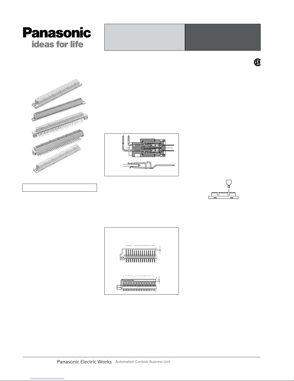
• Time difference contact function
Header
Socket
Dual surface contacting construction
Mating
diagram
Standard
contacts
Time difference
contacts
1mm
1.2mm
Standard
contacts
Time difference
contacts
Incorrect insertion prevention key
panasonic-electric-works.net/ac
Connectors for industrial equipment
DIN CONNECTORS (AXD)
ORDERING INFORMATION
SPECIFICATIONS
1. Characteristics
Item Specifications Conditions
Electrical
characteristics
Rated current 2A
Rated voltage 300V AC
Breakdown voltage 1,000 V AC for 1 min. Detection current: 1mA
Insulation resistance Min. 1,000MΩ at 500V DC megger
Contact resistance Max. 20mΩ
Measured based on the HP4338B measurement method of
JIS C 5402.
Mechanical
characteristics
Composite insetion force Max. 0.843N {86gf} × no. of contact
Unit removal force Min. 0.15N {15.3gf}
Measured by steel gauge with 0.56(t)×0.8(W)mm and
smoothness 0.1s.
Post holding force Min. 19.6N {2kgf} (header side)
Lifetime
characteristics
Insertion and removal life 1,000 times
Environmental
characteristics
Ambient temperature –55°C to +125°C At less than 85% R.H. (No freezing at low temperature)
Soldering temperature
resistance
260°C: within 10 sec.
300°C: within 5 sec.
350°C: within 3 sec.
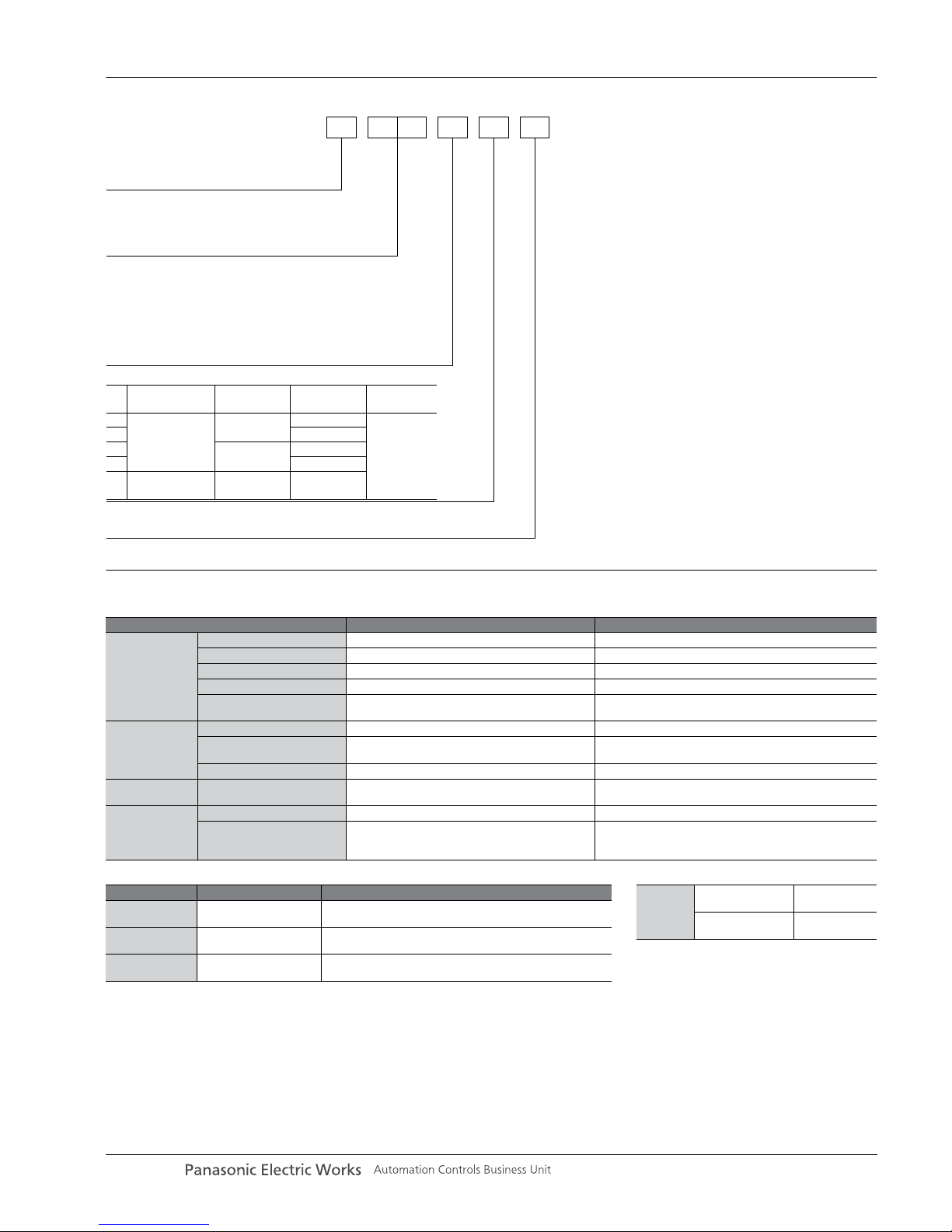
<Surface treatment (Contact portion/Terminal portion>
1: Au plating/Sn plating
DIN connectors
1: Socket
2: Header
<Type and contacts layout>
2: B type (2 rows terminal pitch: 2.54 mm)
3: C type (The middle row is removed terminal pitch: 5.08 mm)
4: C type (3 rows terminal pitch: 2.54 mm)
6: R type (The middle row is removed terminal pitch: 5.08 mm)
7: R type (3 rows terminal pitch: 2.54 mm)
8: Q type (2 rows terminal pitch: 2.54 mm)
AXD 1
<No. of contacts (2 digits)>
20: 20 contacts 32: 32 contacts 44: 44 contacts
50: 50 contacts 64: 64 contacts 90: 90 contacts
96: 96 contacts 00: 100 contacts
<Terminal shape and product types>
No.
PC board
mountig form
0
1
PC board top
mounting type
PC board edge
mounting type
Self-clinching
bracket
Not available
Not available
Flux
resistant
Not available
Not available
Terminal
shape
DIP terminal
2 Available
5
Available
Not available
7 Available
2. Material and surface treatment
Note) Please consult us for different plating requirements.
Part name Material Surface
Molded portion
Glass reinforced PBT
(UL94V-0)
—
Socket contact Copper alloy
Contact portion: Ni plating on base, Au plating on surface
Te r minal portion: Ni plating on base, Sn plating on surface
Header post Brass
Contact portion: Ni plating on base, Au plating on surface
Te r minal portion: Ni plating on base, Sn plating on surface
3. Applicable PC board
PC board
thickness
B, C type socket
Q, R type header
1.6 to 2.4mm
B, C type header
Q, R type socket
1.6mm
panasonic-electric-works.net/ac
Connectors for industrial equipment
DIN CONNECTORS (AXD)
INTRODUCTION OF OTHER TYPES
2. FEATURES AND CONSTRUCTION OF DIN CONNECTOR WITH HIGHER FUNCTION
1. FEATURES OF REVERSE TYPE DIN
CONNECTOR
New series of reverse types popular in
the U.S.A.
1) Shock resistant socket construction
Integrated construction of the flange and
housing prevent damage to the terminals
from shock.
2) Box-shaped header provides excellent
electrical performance
Box-shaped headers feature long
insulation distance between the
connector and mounting panel and low
capacitance.
Body
Contact
Flange
OPEN type
Former product
BOX type
Mounting panel
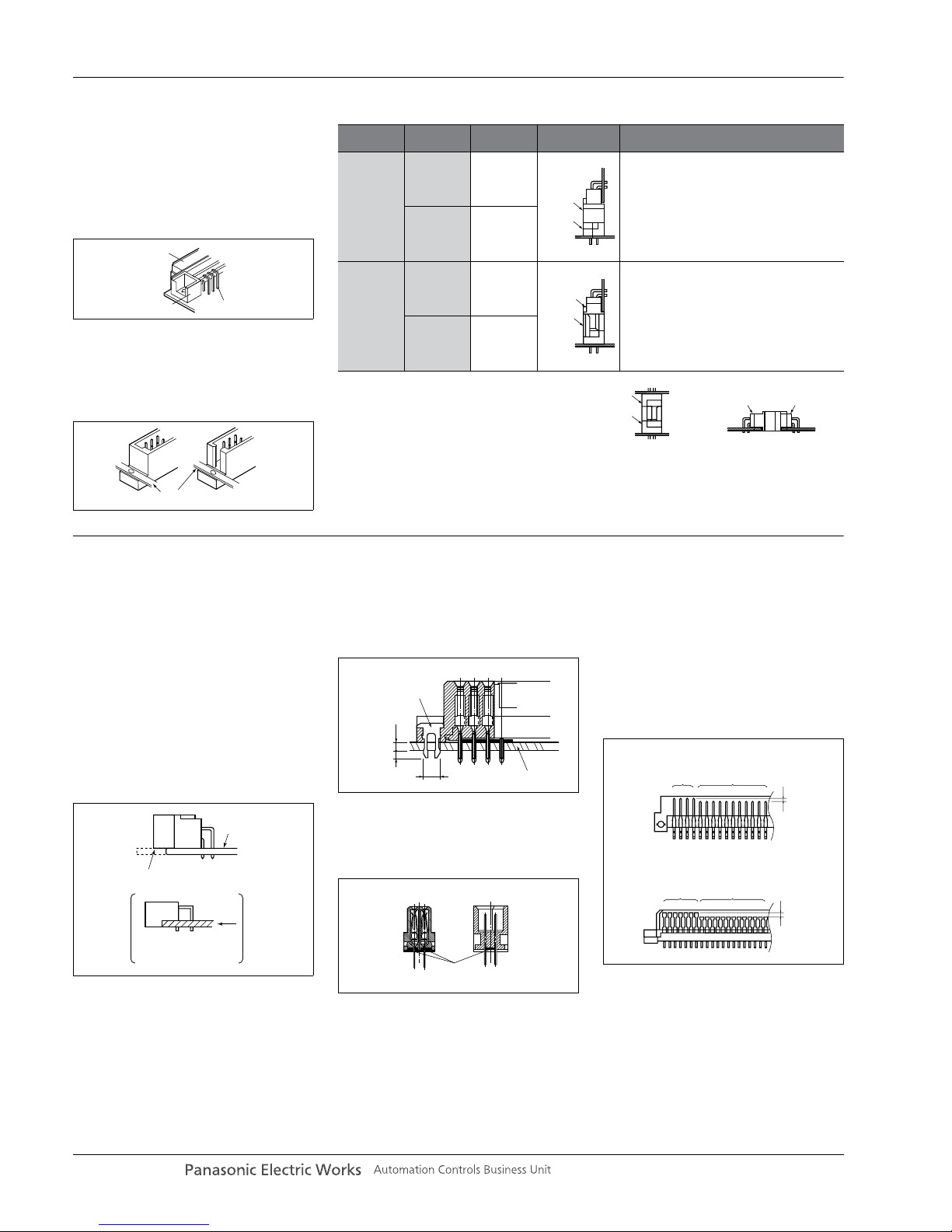
Standard type and reverse type
Types
Header/
socket
Te r minal
shape
Form
Standard
type
Header Angle
The contacts of the socket mounted on the
mother board (power supply side) are covered
to prevent electrical shock and entry of foreign
matter.
Socket Straight
Reverse
type
Header Straight
1. Reduction of total cost
Since the cost of the header is low, it is more
economical to use the header for mother
boards which require multiple pins for
expansion.
2. Matches the designer's requirements for
maximum simplicity in the mother board design.
Socket Angle
The header and socket for the standard
type and reverse type fit each other,
this permits the connections shown in
the figure on the right.
Stacking connection Horizontal connection
Srandard
header
Standard
socket
Reverse
header
Reverse
socket
Standard
socket
Reverse
header
Reverse
socket
Srandard
header
DIN connector enhancement products
which support user circuit designs and
solve problems that occur during
connector mounting.
• PC board top mounting type
• Self-clinching bracket (with temporary
fastening function)
• Flux resistant construction
• Time difference contacts
1) PC board top mounting type
• Prevents the entry of flux during
automatic soldering.
• Large position tolerance when mounting
the connector to the PC board permits
the use of automatic mounting.
2) Self-clinching brackets
(with temporary function)
• Prevents the connector from shifting
due to vibration and shock.
• Uses the same mounting hole as the
mounting screw.
3) Flux resistant construction
The terminals are sealed with resin to
prevent seepage of flux through the
terminals or entry of flux from the bottom
of the connector.
4) Time difference contacts
• ICs are protected from damage at
connection even if the PC board is
inserted or removed without power
connected during maintenance or
inspection. This simplifies circuit design.
•A contact time difference of 1mm for
headers and 1.2mm for sockets is
obrained.
• Time difference contacts can be
arranged as desired.
PC board
Snap off at the notches
after soldering
PC board edge
mounting type
(DIN connector)
mm
Self-clinching bracket
PC board
PC board
mounting hole
2.8±0.05 dia.
1.6
1.4
Sealed
with
resin
Cross section
HeaderSocket
Header
Socket
Standard
contacts
Time difference
contacts
1mm
1.2mm
Standard
contacts
Time difference
contacts
panasonic-electric-works.net/ac
Connectors for industrial equipment
DIN CONNECTORS (AXD)
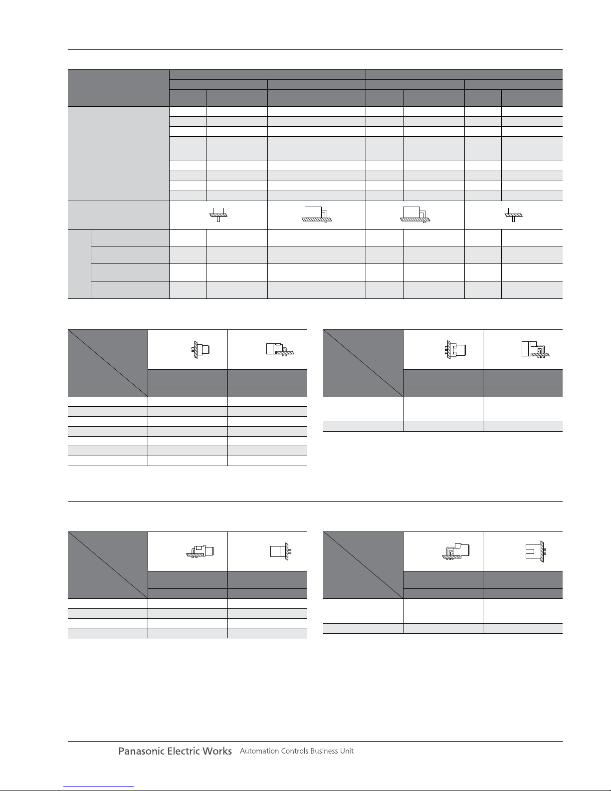
PRODUCT TABLE
PRODUCT TYPES (STANDARD)
PRODUCT TYPES (REVERSE)
Type
Socket Header
Standard types Reverse types Standard types Reverse types
B type
2 rows
C type
3 rows
Q type
2 rows
R type
3 rows
B type
2 rows
C type
3 rows
Q type
2 rows
R type
3 rows
No. of contacts
100 100 100 100
96 96 96 96
90 90
64
64
(The middle row
is removed)
64
64
(The middle row
is removed)
64
64
(The middle row
is removed)
64
64
(The middle row
is removed)
50 50 50 50
44 44
32 32 32 32
20 20
Te r minal shape
Higher functional
products availability
PC board top mounting
type
——Available Available Available Available — —
Self-clinching bracket
(temporary fastening)
Available Available Available Available Available Available Available Available
Flux-resistant
construction
Available Available ————Available Available
Time difference
contacts
Available Available — — Available Available Available Available
1) B type (standard 2 rows)
Notes: 1. All are tray packaged. Packing quantity for outer carton is 200 pcs.
2. For the available foreign standard products, refer to “STANDARDS
CHART” on the end of the catalog.
2) C type (standard 3 rows)
Notes: 1. All are tray packaged. Packing quantity for outer carton is 200 pcs.
2. For the available foreign standard products, refer to “STANDARDS
CHART” on the end of the catalog.
Shape
No. of contacts
Socket Header
Solder-dip
straight terminals
Solder-dip
angle terminals
Par t No. Part No.
20 AXD120201 AXD220211
32 AXD132201 AXD232211
44 AXD144201 AXD244211
50 AXD150201 AXD250211
64 AXD164201 AXD264211
90 AXD190201 AXD290211
100 AXD100201 AXD200211
Shape
No. of contacts
Socket Header
Solder-dip
straight terminals
Solder-dip
angle terminals
Par t No. Part No.
64
(The middle row is
removed)
AXD164301 AXD264311
96 AXD196401 AXD296411
1) Q type (reverse 2 rows)
Notes: 1. All are tray packaged. Packing quantity for outer carton is 200 pcs.
2. Adopting box shape, Q types differ from DIN international standards
(open shape) on the mounting spacing.
2) R type (reverse 3 rows)
Note: All are tray packaged. Packing quantity for outer carton is 200 pcs.
Shape
No. of contacts
Socket Header
Solder-dip
angle terminals
Solder-dip
straight terminals
Par t No. Part No.
32 AXD132811 AXD232801
50 AXD150811 AXD250801
64 AXD164811 AXD264801
100 AXD100811 AXD200801
Shape
No. of contacts
Socket Header
Solder-dip
angle terminals
Solder-dip
straight terminals
Par t No. Part No.
64
(The middle row is
removed)
AXD164611 AXD264601
96 AXD196711 AXD296701
panasonic-electric-works.net/ac
 Loading...