

Page 1
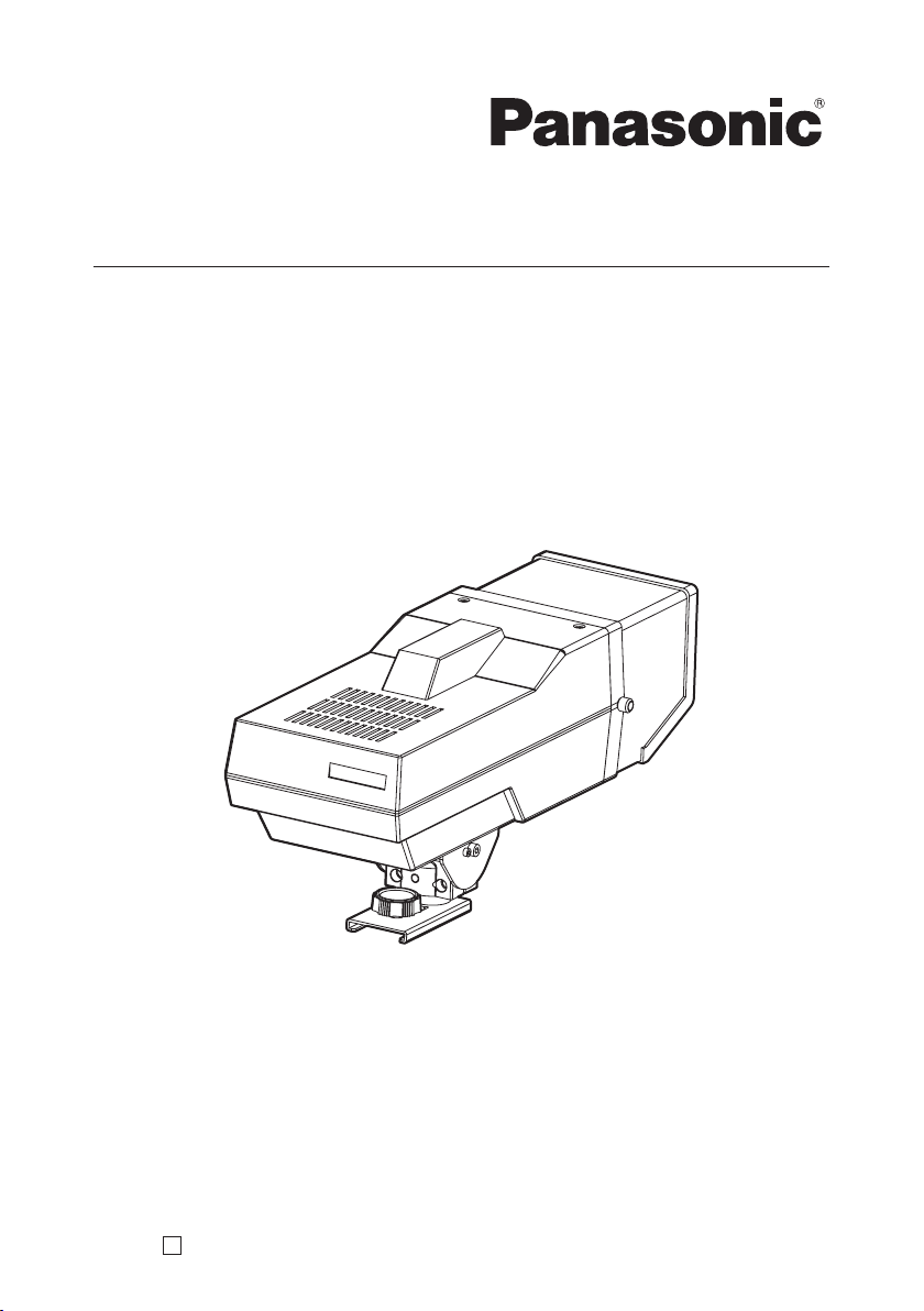
Operating Instructions
4 CRT Viewfinder
Model No. AW-VF64N
Before operating this product, please read the instructions carefully and save this manual for
future use.
F0906Y0 D VQTB0132
Page 2
Safety precautions
CAUTION
RISK OF ELECTRIC SHOCK
DO NOT OPEN
CAUTION: TO REDUCE THE RISK OF ELECTRIC SHOCK,
DO NOT REMOVE COVER (OR BACK).
NO USER SERVICEABLE PARTS INSIDE.
REFER TO SERVICING TO QUALIFIED SERVICE PERSONNEL.
The lightning flash with arrowhead symbol, within an equilateral triangle,
is intended to alert the user to the presence of uninsulated “dangerous
voltage” within the product’s enclosure that may be of sufficient magnitude
to constitute a risk of electric shock to persons.
The exclamation point within an equilateral triangle is intended to alert
the user to the presence of important operating and maintenance
(service) instructions in the literature accompanying the appliance.
For CANADA
This Class A digital apparatus complies with Canadian ICES-003.
Cet appareil numérique de la class A est conforme à la norme
NMB-003 du Canada.
FCC Note:
This equipment has been tested and found to comply with the limits for a class A
digital device, pursuant to Part 15 of the FCC Rules. These limits are designed
to provide reasonable protection against harmful interference when the
equipment is operated in a commercial environment. This equipment generates,
uses, and can radiate radio frequency energy, and if not installed and used in
accordance with the instruction manual, may cause harmful interference to radio
communications. Operation of this equipment in a residential area is likely to
cause harmful interference in which case the user will be required to correct the
interference at his own expense.
Warning:
To assure continued FCC emission limit compliance, the user must use
only shielded interface cables when connecting to external units. Also, any
unauthorized changes or modifications to this equipment could void the user’s
authority to operate it.
indicates safety information.
- 2 -
Page 3
Safety precautions
WARNING:
• TO REDUCE THE RISK OF FIRE OR SHOCK HAZARD, DO NOT EXPOSE
THIS EQUIPMENT TO RAIN OR MOISTURE.
• TO REDUCE THE RISK OF FIRE OR SHOCK HAZARD, KEEP THIS
EQUIPMENT AWAY FROM ALL LIQUIDS. USE AND STORE ONLY IN
LOCATIONS WHICH ARE NOT EXPOSED TO THE RISK OF DRIPPING OR
SPLASHING LIQUIDS, AND DO NOT PLACE ANY LIQUID CONTAINERS ON
TOP OF THE EQUIPMENT.
CAUTION:
TO REDUCE THE RISK OF FIRE OR SHOCK HAZARD AND ANNOYING
INTERFERENCE, USE THE RECOMMENDED ACCESSORIES ONLY.
Note:
The rating plate (serial number plate) is on the bottom of the unit.
indicates safety information.
- 3 -
Page 4
Safety precautions
IMPORTANT SAFETY
INSTRUCTIONS
Read these operating instructions carefully before using the unit. Follow the safety
instructions on the unit and the applicable safety instructions listed below. Keep
these operating instructions handy for future reference.
1) Read these instructions.
2) Keep these instructions.
3) Heed all warnings.
4) Follow all instructions.
5) Do not use this apparatus near
water.
6) Clean only with dry cloth.
7) D o not block any ve n t i l a t i on
openings. Install in accordance with
the manufacturer’s instructions.
8) D o no t instal l ne ar a ny h e at
sources such as radiators, heat
re g is t er s , s t o ve s, or o t her
apparatus (including amplifiers)
that produce heat.
9) Do not defeat the safety purpose
of the pol arized or groundingtype plug. A polarized plug has
two blades with one wider than the
other. A grounding-type plug has
two blades and a third grounding
prong. The wide blade or the third
prong are provided for your safety.
If the provided plug does not fit
into yo u r o u t le t, consu l t a n
electrician for replacement of the
obsolete outlet.
10) Protect the power cord form being
walked on or pinched particularly
at plugs, convenience receptacles,
and the point where they exit from
the apparatus.
11) Only use attachments/accessories
specified by the manufacturer.
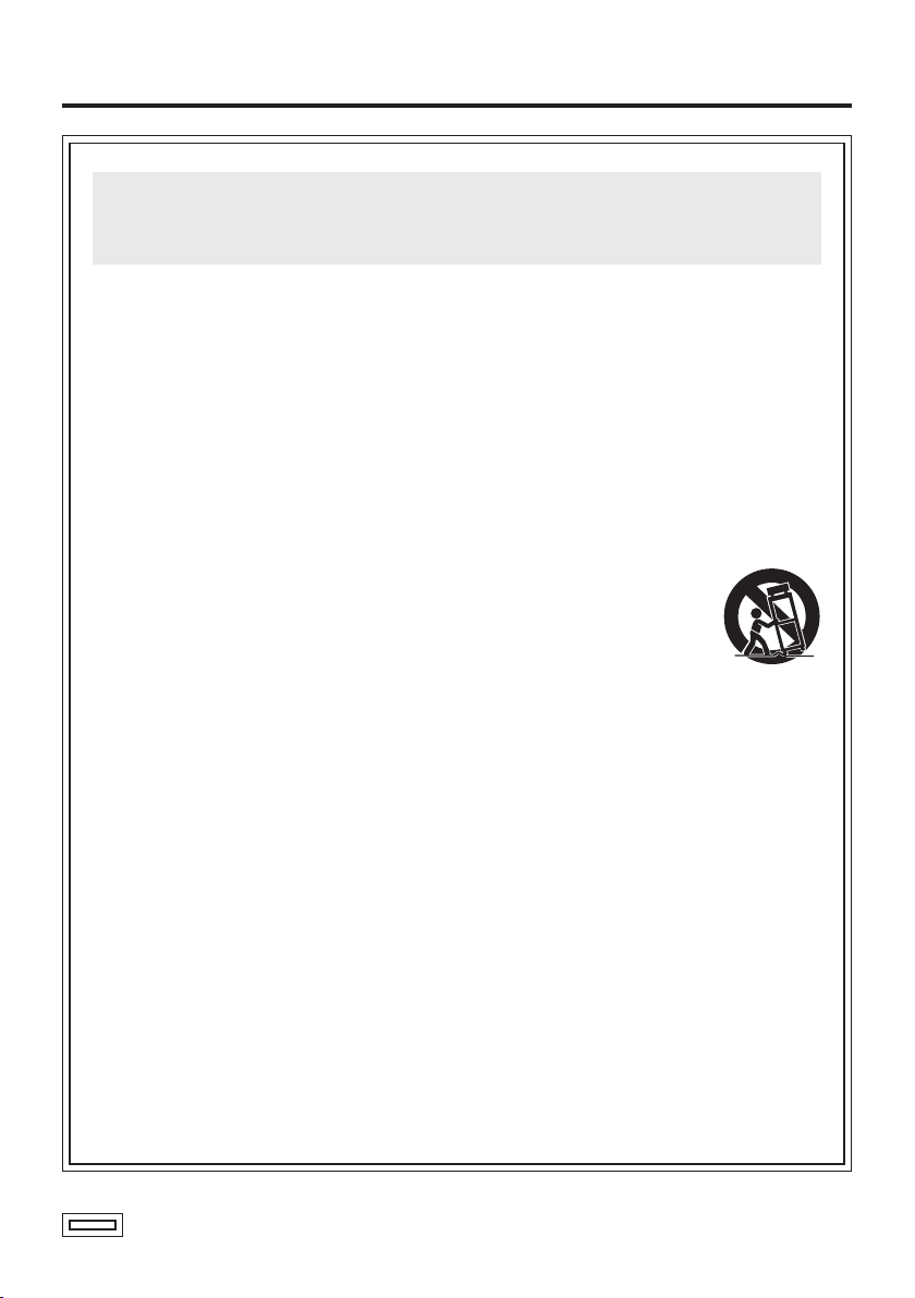
12) Use only with the cart,
stand, tripod, bracket,
or table specified by
the manufacturer, or
sold
with the apparatus. When a cart is
used, use caution when moving
the cart/apparatus combination to
avoid injury from tip-over.
13) Unp l ug this appara tus during
lightning storms or when unused
for long periods of time.
14) Refer all servicing to qualified
service personnel. Ser vicin g is
required when the apparatus has
been damaged in any way, such
as power-supply cord or plug is
damaged, liquid has been spilled
or objects have fallen into the
apparatus, the apparatus has been
exposed to rain or moisture, does
not operate normally, or has been
dropped.
indicates safety information.
- 4 -
Page 5

Contents
Accessories .......................................... 5
Introduction ...........................................
Major operating controls and
their functions ................................. 6
How to install
........................................ 7
How to detach the hood
How to adjust the viewfinder angle
5
Appearance ......................................... 10
Specifications ..................................... 11
....................... 9
.... 9
Accessories
Mounting base ....................................... 1
Mounting base screws .......................... 2
Introduction
This 4-inch CRT viewfinder is designed to be used with a convertible camera (such as
the AW-E350, AW-E650, AW-E655, AW-E750 or AW-E860).
The studio SDI card (AW-PB506A) or studio card (AW-PB305A) is required in order to
attach the unit to the convertible camera.
Notes
The AW-VF64 cannot be installed to the following models;
AW-E300, AW-E300A, AW-E300S, AW-E600, AW-E800, AW-E800A, AW-RP605,
AW-PB605
The ranges within which the operation of this unit is guaranteed are as follows:
Supply voltage: 10.5 V to 15.0
Ambient temperature:
These ranges are more limited than the guaranteed operating ranges of other
convertible cameras.
Ensure that the unit is used within the ranges given here without fail: otherwise,
trouble may result.
Do not connect or disconnect the EVF connector while the unit’s power is still on.
Doing so may result in viewfinder trouble.
Noise may interfere with the pictures shown if the unit is used in a location with strong
electrical or magnetic fields, such as near the transmitting antenna of a TV, radio
broadcast station, or near a motor.
When the viewfinder unit is to be discarded at the end of its service life, ask a
specialized contractor to dispose of it properly in order to protect the environment.
+32°F to +104°F (0°C to +40°C)
V
- 5 -
Page 6

Major operating controls and their functions
Hood
This is used to block extraneous light
which, when present, makes it hard to
see the screen. The unit comes with the
hood already mounted.
For details on how to detach the hood,
refer to page 9.
Tally lamp
This lights when the camera is on the
air.
Pan/tilt lock knob
This is used to adjust the angle of the
viewfinder.
First loosen it, decide on the position of
the viewfinder, and then tighten it up to
secure.
Shoe fixture
Shoe fixing screw
This is used to secure the viewfinder to
the interface bracket.
EVF connector
This is connected to the EVF connector
2 on the interface bracket.
Fixing screws (2)
These are used to secure the hood.
Tally lamp (Top)
This lights when the camera is on the air.
It lights in tandem with tally lamp .
Contrast control [CONT.]
This is used to adjust the contrast of the
images shown on the viewfinder screen.
Brightness control [BRIGHT.]
This is used to adjust the brightness of
the viewfinder screen.
- 6 -
Page 7

How to install
Mounting to the interface bracket (AW-PB506A, AW-PB305A)
Mount the interface bracket on the
tripod. (Screw: 1/4 – 20UNC)
Mount the camera on the interface
bracket (AW-PB506A or AW-PB305A),
and turn the fixing knob to tighten the
camera securely.
Interface bracket:
AW-PB506A,
AW-PB305A
Connect the EVF I/F cable (or EVF
cable)from the interface bracket to the
EVF I/F connector (or EVF connector)
on the camera.
Fixing knob
EVF I/F cable
- 7 -
Page 8

How to install
Mount the mounting base that is
supplied to the viewfinder onto the top of
the interface bracket using the 2 screws
provided.
( Mount the base securely so that it is not
unsteady.)
Slide the viewfinder from the back into
the mounting base on the top of the
interface bracket, and push it into place
completely until it stops.
Turn the shoe fixing screw , and
tighten the viewfinder securely.
Connect the EVF connector from the
viewfinder to the EVF connector 2 on
the interface bracket.
Notes
Before connecting the connector,
make sure that the power to all the
equipment has been turned off.
For details on the connections of
each device, refer to the operating
instructions of the convertible camera,
studio SDI card (AW-PB506A) and
studio card (AW-PB305A).
Mounting base
2 screws
- 8 -
Page 9

How to detach the hood
Slide-in slot
Loosen the hood fixing screws , one at the left and one at the right, and pull the hood
free.
Return the hood fixing screws to their original positions, and tighten them up.
To re-attach the hood, first loosen the hood fixing screws , and insert the hood from
the front along the slide-in slots. Insert it firmly as far as it will go, and then secure it
using the hood fixing screws
.
How to adjust the viewfinder angle
Panning
Tilting
To adjust the viewfinder angle, loosen the pan/tilt lock knob , set the viewfinder to an
angle at which the screen can easily be seen, and then tighten the knob to secure the
viewfinder in place.
- 9 -
Page 10

Appearance
4-1/2
(114)
Unit: inch (mm)
9-5/8 (244)
5-1/16 (128)
13 (330)
6-1/4 (158)
- 10 -
Page 11

Specifications
Power requirements
Power consumption: Approx. 9 W
indicates safety information.
CRT:
Video input:
Resolution:
Internal indicator:
Adjustment function:
Operating temperature: +32°F to +104°F (0°C to +40°C)
Ambient operating humidity: 10% to 80% (without condensation)
Dimensions (WHD): 5-1/16”6-1/4”13” (128158330 mm)
Weight:
Finish: Main unit; Black resin molded part
Hood; Painted black
Weight and dimensions indicated above are approximate.
Specifications are subject to change without notice.
Approx. 3.5 lbs. (1.6 kg)
: DC 12 V (supplied from camera head)
4-inch black-and-white CRT
1.0 V [P-P] composite/high impedance
More than 500 lines
Tally indication (LED)
Contrast, brightness
(excluding protrusions)
- 11 -
Page 12

PANASONIC BROADCAST & TELEVISION SYSTEMS COMPANY
UNIT COMPANY OF PANASONIC CORPORATION OF NORTH AMERICA
Executive Office:
One Panasonic Way 4E-7, Secaucus, NJ 07094 (201) 348-7000
EASTERN ZONE:
One Panasonic Way 4E-7, Secaucus, NJ 07094 (201) 348-7621
Southeast Region:
1225 Northbrook Parkway, Ste 1-160, Suwanee, GA 30024 (770) 338-6835
Central Region:
1707 N Randall Road E1-C-1, Elgin, IL 60123 (847) 468-5200
WESTERN ZONE:
3330 Cahuenga Blvd W., Los Angeles, CA 90068 (323) 436-3500
Government Marketing Department:
52 West Gude Drive, Rockville, MD 20850 (301) 738-3840
Broadcast PARTS INFORMATION & ORDERING:
9:00 a.m. – 5:00 p.m. (PST) (800) 334-4881/24 Hr. Fax (800) 334-4880
Emergency after hour parts orders (800) 334-4881
TECHNICAL SUPPORT:
Emergency 24 Hour Service (800) 222-0741
Panasonic Canada Inc.
5770 Ambler Drive, Mississauga, Ontario L4W 2T3 (905) 624-5010
Panasonic de Mexico S.A. de C.V.
Av angel Urraza Num. 1209 Col. de Valle 03100 Mexico, D.F. (52) 1 951 2127
Panasonic Puerto Rico Inc.
San Gabriel Industrial Park, 65th Infantry Ave., Km. 9.5, Carolina, Puerto Rico 00630
(787) 750-4300
© 2006 Matsushita Electric Industrial Co., Ltd. All rights reserved.
 Loading...