

Page 1
AW- P
Before attempting to connect, operate or adjust this product, please read these
instructions completely.
Indoor Pan/Tilt Head
Page 2
2
Safety precautions
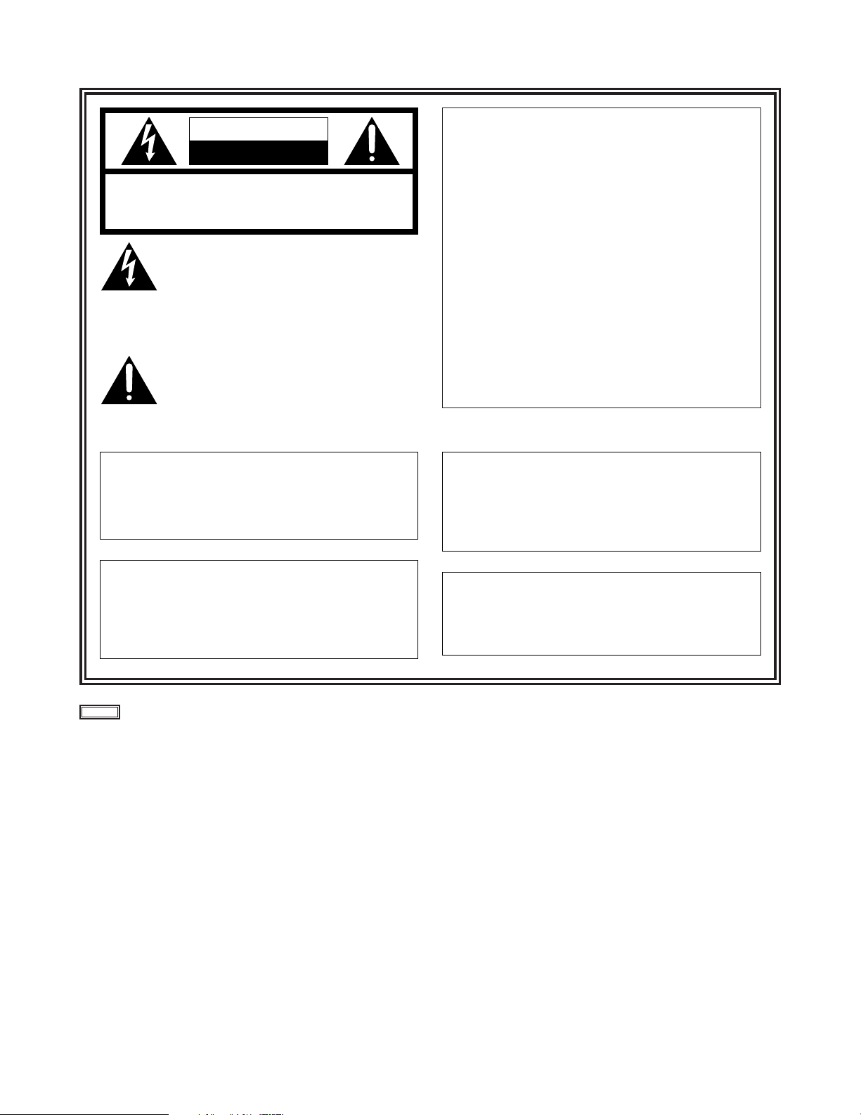
FCC Note:
This device complies with Part 15 of the FCC Rules.
To assure continued compliance follow the attached
installation instructions and do not make any
unauthorized modifications.
This equipment has been tested and found to comply
with the limits for a class A digital device, pursuant to
Part 15 of the FCC Rules. These limits are designed
to provide reasonable protection against harmful
interference when the equipment is operated in a
commercial environment. This equipment generates,
uses, and can radiate radio frequency energy and, if
not installed and used in accordance with the
instruction manual, may cause harmful interference to
radio communications. Operation of this equipment in
a residential area is likely to cause harmful
interference in which case the user will be required to
correct the interference at his own expense.
indicates safety information.
CAUTION
RISK OF ELECTRIC SHOCK
DO NOT OPEN
CAUTION: TO REDUCE THE RISK OF ELECTRIC SHOCK,
DO NOT REMOVE COVER (OR BACK).
NO USER SERVICEABLE PARTS INSIDE.
REFER TO SERVICING TO QUALIFIED SERVICE PERSONNEL.
The lightning flash with arrowhead symbol,
within an equilateral triangle, is intended to
alert the user to the presence of uninsulated
“dangerous voltage” within the product’s
enclosure that may be of sufficient magnitude
to constitute a risk of electric shock to
persons.
The exclamation point within an equilateral
triangle is intended to alert the user to the
presence of important operating and
maintenance (service) instructions in the
literature accompanying the appliance.
CAUTION:
TO REDUCE THE RISK OF FIRE OR SHOCK
HAZARD AND ANNOYING INTERFERENCE,
USE THE RECOMMENDED ACCESSORIES
ONLY.
WARNING:
TO REDUCE THE RISK OF FIRE OR SHOCK
HAZARD, DO NOT EXPOSE THIS
EQUIPMENT TO RAIN OR MOISTURE.
CAUTION:
TO REDUCE THE RISK OF FIRE OR SHOCK
HAZARD, REFER CHANGE OF SWITCH
SETTING INSIDE THE UNIT TO QUALIFIED
SERVICE PERSONNEL.
Replace battery with part No. CR2032 only.
Use of another battery may present a risk of fire or
explosion.
Caution—Battery may explode if mistreated.
Do not recharge, disassemble or dispose of in fire.
Page 3

3
Thank you very much for purchasing the AW-PH500 indoor pan/tilt head. This pan/tilt head is designed to be used with
electronic news gathering (ENG) cameras. A studio pan/tilt head system can be constructed by using the AW-PH500 in
combination with any model in the AW-F575 series of ENG cameras.
Overview
≥ This stand-alone indoor pan/tilt head for ENG applications enables the camera to be turned 95 degrees upward, 95
degrees downward and 300 degrees on the horizontal.
≥ A total weight of 15 kg including the camera and lens can be supported.
≥ Direct control can be exercised from the AW-RP301 pan-tilt control panel. (However, the camera itself cannot be controlled
from the panel).
≥ The pan/tilt head can be controlled directly from the AW-RP501 hybrid control panel.
≥ When the AW-RP305 multi-control panel or AW-RP505 multi-hybrid control panel is used, up to five pan/tilt heads can be
controlled directly through the AW-HB505 multi-port hub. (However, the camera itself cannot be controlled from the AWRP305).
≥ Control can be exercised from a PC, etc. using the RS-232C interface. (Up to 50 points can be preset when control is
exercised using the RS-232C interface).
≥ Control can be exercised using a contact-type controller.
Check the accessories supplied
Contents
Safety precautions .................................................................................. 2
Overview................................................................................................... 3
Check the accessories supplied ............................................................ 3
Operating precautions ............................................................................ 4
∫How to replace the battery ......................................................................................... 4
Installation precautions .......................................................................... 4
Parts and their functions ........................................................................ 5
Attaching the pan/tilt head ..................................................................... 7
∫Assembling the pan/tilt head ...................................................................................... 7
∫Installation procedures ............................................................................................... 8
Connections............................................................................................ 10
∫When using the control panel.................................................................................... 10
∫Connecting the cables to the pan/tilt head ................................................................ 13
∫When using the RS-232C interface to control the pan/tilt head ................................ 15
∫
When using the RS-232C interface and control panel to control the pan/tilt head
.......... 16
∫Exercising control using contacts.............................................................................. 16
Specifications ......................................................................................... 17
Warranty and after-sales service .......................................................... 18
≥ Rotary arm (aa1)
≥ Rotary arm anchoring screws (aa8)
≥ Rotary arm anchoring flat washer (aa8)
≥ Rotary arm anchoring spring washer (aa8)
≥ Camera mounting board anchoring screws (aa2)
≥ Flat washers (aa2)
≥ Spring washers (aa2)
Page 4
4
Installation precautions
≥ In deciding where to attach the pan/tilt head, give due consideration to the weight of the pan/tilt head and the weight of the
camera to be mounted on it, and select a flat and level location where the pan/tilt head can be firmly secured. Secure the
pan/tilt head firmly so that it will not shake, rock or wobble whether it is stationary or rotating. Read through the installation
procedure and install the pan/tilt head securely.
≥ A camera weighing up to 15 kg can be mounted on the pan/tilt head. A camera weighing more than 15 kg including the
weight of its lens cannot be used.
≥ No screws for attaching the pan/tilt head are provided with the pan/tilt head. Select the screws to be used by giving due
consideration to the location where the pan/tilt head is to be attached and the weight of the camera which will be mounted
on the pan/tilt head.
≥ Do not install the pan/tilt head in an extremely hot or cold location where the temperature will drop below –20 oC or rise
above +60 oC since doing so will give rise to instability in the operation of the pan/tilt head.
≥ To supply power to the pan/tilt head, be sure to use only the AW-PS505 AC adapter designed exclusively for this pan/tilt
head.
≥ The maximum power which can be supplied to the camera is 2 A (DC 12 V).
≥ Do not use your hands to turn the rotating parts.
Doing so may cause malfunctioning.
≥ Before installing the pan/tilt head, be absolutely sure to turn its power off.
≥ Before checking the pan/tilt head’s operations and actually using it, always check to ensure that nobody is within the
rotational range of the pan/tilt head.
Operating precautions
In addition to the “Safety precautions,” please heed the precautions described below.
This pan/tilt head uses a manganese dioxide-lithium battery (CR2032). Be absolutely sure to remove this battery when the
pan/tilt head is to be scrapped or its printed circuit board is to be scrapped. Be absolutely sure to comply with the regulations
applicable in the country concerned that govern the disposal of batteries which have been removed from equipment and
batteries which have been replaced. Do not dispose of this battery as household garbage.
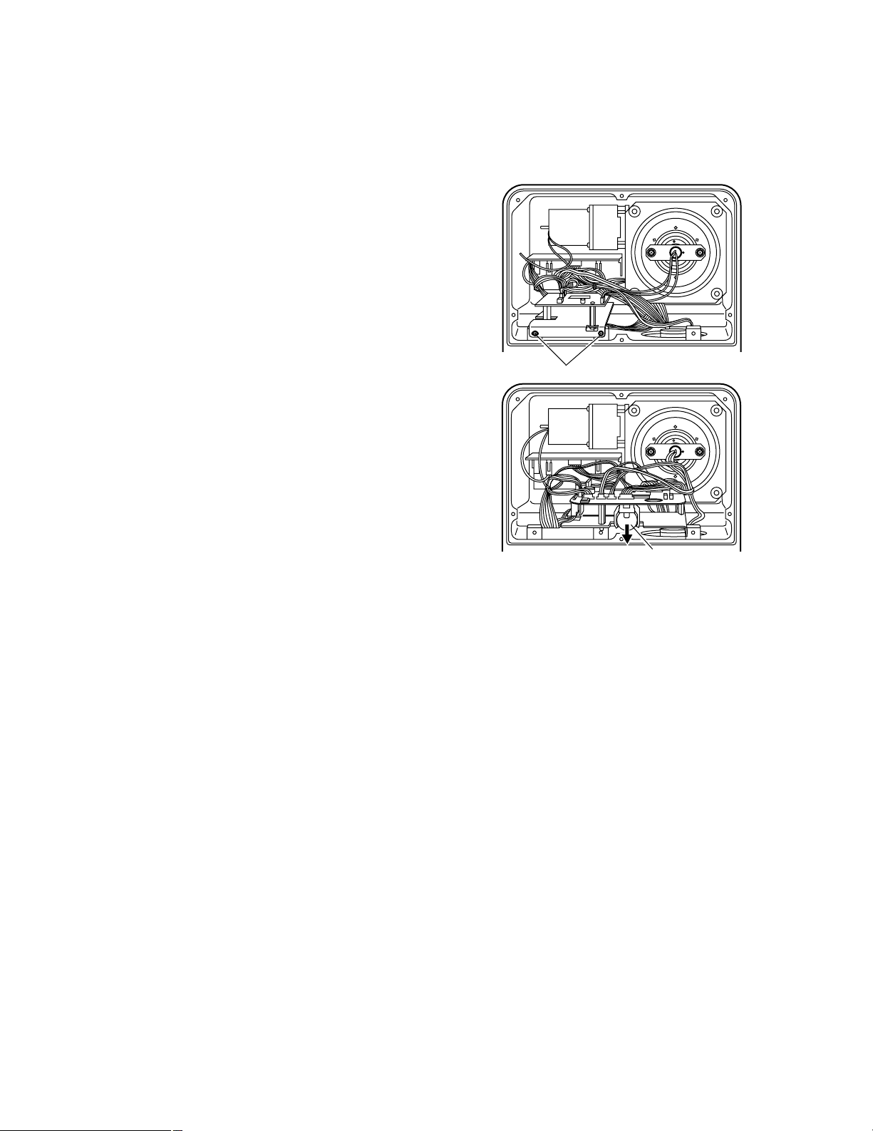
∫How to replace the battery
1. Remove the panel by removing the six screws on
the side opposite to the one with the rotary arm.
Screws (aa2)
Battery
3. Pull down the battery to remove it, and then install a
replacement battery.
2. Remove the two screws shown in the figure on the
right, and draw out the circuit board.
Page 5
5
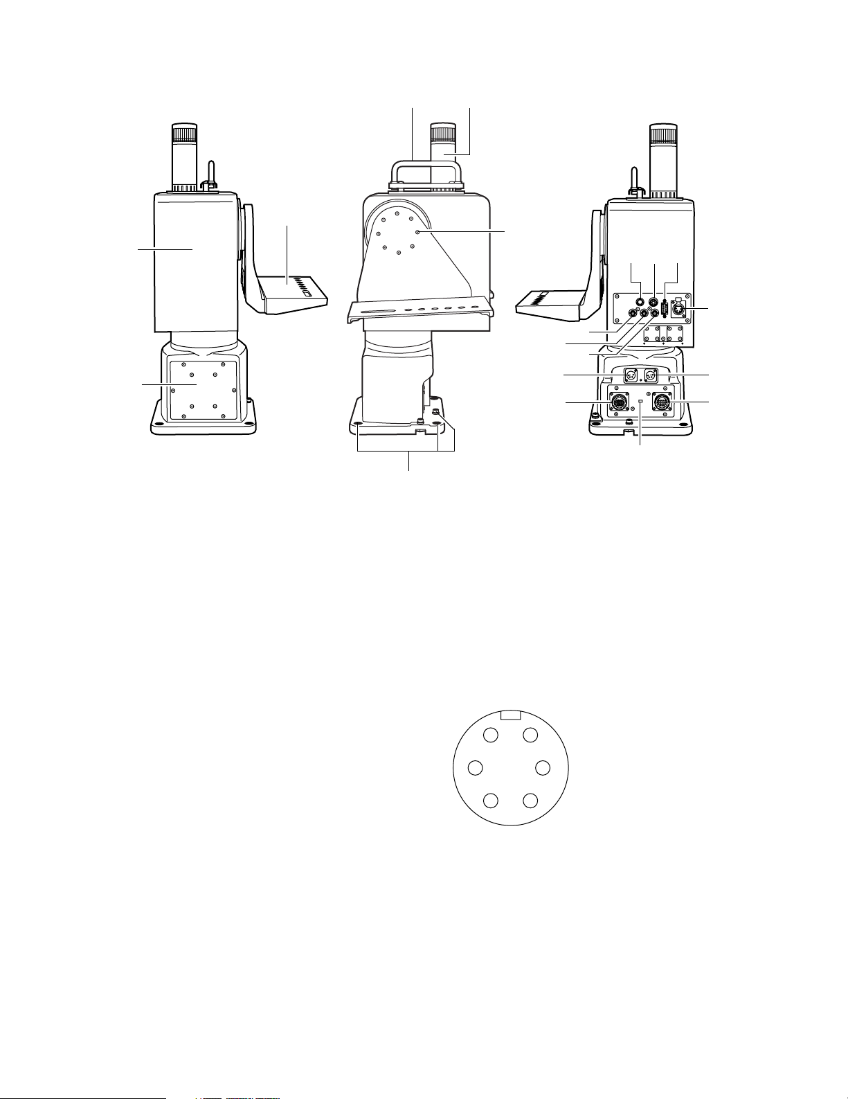
Parts and their functions
45
6
:89
;
@?
A
C
B
<
=
1
3
7
>
2
1
Rotary head
This rotates in the panning direction.
2
Pedestal
3
Rotary arm
The ENG camera is mounted on this arm. The arm
rotates in the tilting direction.
4
Grip
This is where the pan/tilt head is held. Use it to carry the
pan/tilt head from one place to another or pick it up when
installing it.
5
Tally lamp
This is lit by the tally ON signal of the hybrid controller or
other device. For further details, refer to the operating
instructions of the controller.
6
Rotary arm anchoring screws (supplied)
These hexagon head bolts (a8) are used to anchor the
rotary arm.
7 Holes for attaching the pan/tilt head
These holes are used for anchoring the pan/tilt head
when it is installed.
8
Lens I/F connector (12-pin round)
This connector is used to control the zooming and
focusing of the motorized lens unit.
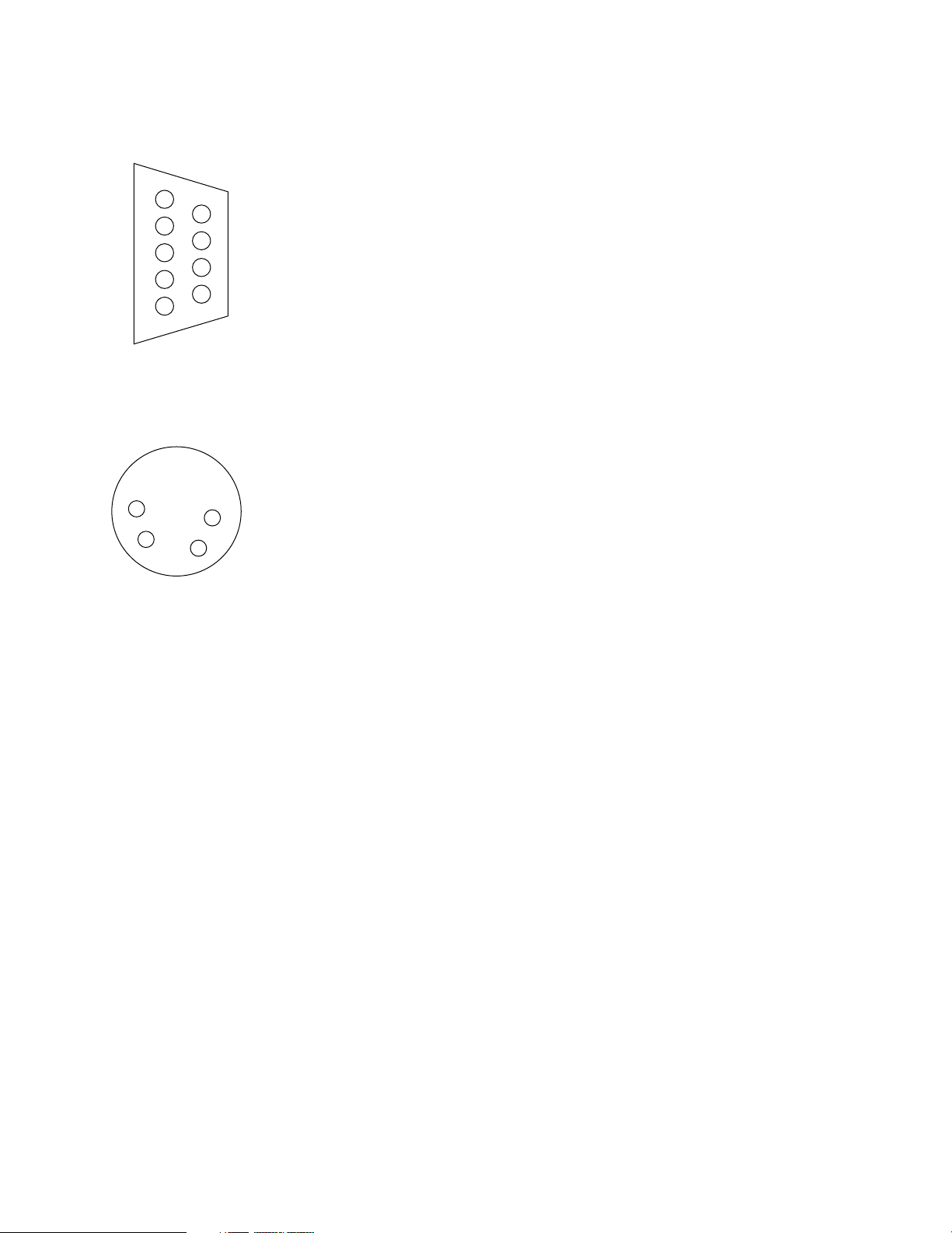
9 ND/EXT CONTROL connector
This output connector is used to perform ON/OFF control
for the motorized ND filter, the ND filter of a lens with a
built-in motorized extender and the lens extender. The
connector has contact outputs. The R03-P6M or R03PB6M connector made by Tajimi Electronics Co., Ltd. is
compatible.
A:ND signal
B:ND return
C:EXT signal
D:EXT return
E:GND
F:VCC (+15 V)
F
A
BE
D
C
Page 6
6
Parts and their functions
@
POWER2 INPUT connector (4-pin Cannon)
The DC 15V power which is supplied from the AW-PS505
AC adapter is connected to this connector.
The power is supplied to the pan/tilt head’s motor only
when the MOTOR POWER SELECT switch C is at the
right setting. Use this connector if the camera has a high
power consumption.
A
P/T CONTROL INPUT connector (24-pin round)
The pan/tilt head control cable (AW-CA24U10, 20 or 30)
is connected to this connector.
Refer to the section entitled “Connections.”
B
CAMERA VIDEO/CONTROL IN/OUT connector
(16-pin round)
The video camera control cable is connected to this
connector.
Refer to the section entitled “Connections.”
C
MOTOR POWER SELECT switch
This switch selects the power input of the pan/tilt head’s
motor. At the left setting, the power input to the
POWER1 connector is used as the power supply of the
pan/tilt head’s motor; at the right setting, the power input
to the POWER2 connector is used.
:
COMPONENT INPUT connector (9-pin D-sub)
The component signals of the camera are input to this
connector.
1: R GND
2: G GND
3: R/P
R/C
4: G/Y/Y
5: B/P
B
6: NC
7: NC
8: B GND
9: NC
;
CAMERA POWER OUT connector (4-pin
Cannon)
The DC 12 V power supplied to the camera is output from
this connector.
1: GND
4: +12 V
< VIDEO IN connector (BNC)
This connector is connected to the video signal connector
on the camera.
(1 V [p-p]/75 h)
=
G/L OUT connector (BNC)
The G/L signals sent from the controller are output from
this connector which is connected to the G/L input
connector on the camera.
>
CAMERA CONTROL OUT connector (BNC)
This connector is connected to the control input
connector on the camera when connecting a camera
which is to be controlled using the AW-RP501 controller.
Refer to page E-11 when the AW-F575 ENG camera is to
be connected.
?
POWER1 INPUT connector (4-pin Cannon)
The DC 15V power which is supplied from the AW-PS505
AC adapter is connected to this connector.
When the MOTOR POWER SELECT switch C is at the
left setting, the power is supplied to both the pan/tilt head
and the camera. When it is at the right setting, the power
which is supplied from the POWER2 INPUT connector is
used as the power supply for the pan/tilt head’s motor.
5
9
4
8
3
7
2
6
1
4
3
1
2
Page 7

7
Attaching the pan/tilt head
(Be absolutely sure to ask your dealer to do this work.)
∫Assembling the pan/tilt head
¥ Setting the cable compensation circuit
A maximum length of up to 500 meters is allowed for the
cables (including the video camera control cable)
between the pan/tilt head and controller when the 5C-2V
cables are used. However, if the cable length is to
exceed 300 meters, set the cable compensation circuit to
ON by following the steps below.
1. Remove the six screws on the side opposite to the
connector panel of the pan/tilt head pedestal, and
pull the panel out toward you.
Screws (aa6)
Circuit board for cable
compensation circuit
ON
OFF
¥ Attaching the rotary arm
Use the rotary arm anchoring screws (a8, supplied),
rotary arm anchoring flat washers (a8, supplied) and
rotary arm anchoring springwashers (a8, supplied) to
attach the rotary arm (supplied) to the pan/tilt head.
Tighten up the screws securely to prevent the arm from
coming loose during use.
2. Set the switch on the printed circuit board attached
to the panel to ON.
3. Return the panel to its original position, and anchor
it using the screws. (Fasten the panel securely.)
Rotary arm
anchoring screws
(aa8)
Rotary arm
anchoring Flat
washer (aa8)
Rotary arm
anchoring Spring
washer (aa8)
Rotary arm
Page 8

8
Attaching the pan/tilt head
(Be absolutely sure to ask your dealer to do this work.)
∫Installation procedure
¥ How to attain camera balance
Be absolutely sure to follow the steps below to attain the camera balance when installing the camera on the pan/tilt head.
1. Position the pan/tilt head so that its tilt axis is on the horizontal, and attach the camera arm.
2. Position the camera using the balance points
specified in the camera’s manual as a guideline,
and use the screw to secure.
If the balance points are not specified, to position
the camera, use the point where the center of
gravity in the perpendicular direction of the camera
with its attached lens is aligned with the tilt rotary
axis, and use the screw to secure.
3. To acquire a reference for positioning while the tilt
axis remains on the horizontal, capture on the
screen a subject which can be clearly verified onscreen, and preset the position in the memory.
<Note>
Depending on the installation conditions, select an
angle at which the camera which will be most often
used in actuality rather than the horizontal.
4. After tilting the camera as far as it will go both
upward and downward from the preset position,
allow the camera to return to the preset position.
1 If the camera goes past the preset position when
it has returned from the upward direction or if it
stops before reaching the preset position when it
has returned from the downward direction
> This means that the front of the camera (lens
side) is too heavy.
Shift the camera’s installation position back.
2 If the camera stops before reaching the preset
position when it has returned from the upward
direction or if it goes past the preset position
when it has returned from the downward
direction
> This means that the back of the camera is too
heavy.
Shift the camera’s installation position forward.
5. By repeating the above steps, even out in both the
upward and downward directions as far as you can
the movement past the preset position or the failure
to return to this position.
Finally, in the slow-motion mode operate the
joystick and make fine adjustments so that the
movements will become smooth.
Tilt rotary axis
Camera’s center
of gravity
Page 9

9
Attaching the pan/tilt head
(Be absolutely sure to ask your dealer to do this work.)
¥ Attaching the AW-F575
Use the WV-QT700 tripod stand to attach the AW-F575 camera.
<Note>
When attaching a camera other than the AW-F575, check its weight and dimensions to confirm whether it can be attached.
≥Attaching the AW-F575 camera
1. While pushing the lock knob on the tripod stand,
move the lock lever in the direction of the arrow.
2. Insert the catch at the rear of the camera into the
groove on the tripod stand.
≥Attaching the tripod stand
Place the WV-QT700 tripod stand on the arm, and anchor
it from below using the two screws supplied with the
pan/tilt head. Be sure to use both flat and spring washers
when anchoring the tripod stand.
<Note>
Use a screwdriver or other such tool to secure the
screws firmly.
3. Place the camera proper on the tripod stand.
4. When the lock lever of the tripod stand is moved in
the direction of the arrow, the camera proper is slid
toward the rear and anchored.
Flat washers
Spring washers
Page 10

10
Connections
∫When using the control panel
¥ Standard connections
O I
O I
AW-PH500
Pan/tilt head
for ENG
applications
AW-PS505
AC adapter
AW-RP301
Pan-tilt control panel
AW-PS301
AC adapter
AW-PS505
AC adapter
Lens zoom / focus cable
ENG camera
Color monitor
Zoom lens
Video camera control cable
AW-CA16U10 (10 meters)
AW-CA16U20 (20 meters)
AW-CA16U30 (30 meters)
Pan/tilt head control cable
AW-CA24U10 (10 meters)
AW-CA24U20 (20 meters)
AW-CA24U30 (30 meters)
Component signals
Video signals (5C-2V coaxial cable)
10 BaseT straight cable
(UTP category 5)
G/L signals
(5C-2V coaxial cable)
Modular joint connector
Max. distance of 500 meters (when extended) between
pan/tilt head and pan-tilt control panel (monitor, G/L source)
<Notes>
≥ If two to five cameras and pan/tilt heads are to be connected, use the AW-RP305 as the controller, and connect the units
through the AW-HB505 multi-port hub. For details on the connections, refer to the operating instructions of the units
concerned.
≥ The distance between the camera pan/tilt head and controller can be extended to 500 meters (maximum) using the
10 BaseT straight cable (UTP category 5).
≥ The cable for outputting the video signals from the camera pan/tilt head and the cable for inputting the G/L signals to the
pan/tilt head can be extended to 500 meters (maximum) using the 5C-2V coaxial cable.
≥ Provide the cables listed below for the connections between the camera and pan/tilt head. Make the cables long enough to
support the connections when the camera is attached to the pan/tilt head and the pan/tilt head is moved upward and
downward.
(Approx. 60 cm: This length differs depending on the camera which is attached and the positions of the camera’s
connectors.)
1
DC power cable (DC 12 V, 4-pin Cannon connector at pan/tilt head end)
2
Video output cable (composite video, BNC connector at pan/tilt head end)
3
G/L input cable (G/L signals, BNC connector at pan/tilt head end)
4
Component output cable (component signals: 9-pin D-sub connector at pan/tilt head end; used only when component
signals are to be output from a camera with component output connectors)
≥ When a motorized zoom lens is used, and its zoom/focus functions are to be controlled from the pan-tilt control panel,
select a cable which is long enough to support the connections when the pan/tilt head is moved upward and downward, as
with the cables listed above.
(Recommended cable: S14 a 7.5BMD-D24 made by Fujinon)
Page 11

11
Connections
¥ When the AW-F575 is used as the camera to be installed
O I
O I
AW-PH500
Pan/tilt head
for ENG
applications
AW-PS505
AC adapter
AW-RP501
Hybrid control panel
AW-PS301
AC adapter
AW-PS505
AC adapter
Lens zoom / focus cable
Connecting cable between camera and pan/tilt head (¢¢1)
AW-F575
AW-F575
Camera adapter
Color monitor
Zoom lens
Video camera control cable
AW-CA16U10 (10 meters)
AW-CA16U20 (20 meters)
AW-CA16U30 (30 meters)
Pan/tilt head control cable
AW-CA24U10 (10 meters)
AW-CA24U20 (20 meters)
AW-CA24U30 (30 meters)
Component signals
Video signals
Camera control signals
G/L signals
10 BaseT straight cable
(UTP category 5)
G/L signals
(5C-2V coaxial cable)
Modular joint connector
Max. distance of 500 meters (when extended) between pan/tilt head
and hybrid control panel (monitor, G/L source)
<Notes>
≥ If the AW-F575 camera is used, the camera can be controlled from the hybrid control panel by performing the connections
as described below.
≥ If two to five cameras and pan/tilt heads are to be connected, use the AW-RP505 as the controller, and connect the units
through the AW-HB505 multi-port hub. For details on the connections, refer to the operating instructions of the units
concerned.
∞ When multiple cameras and pan/tilt heads are to be controlled, priority is given to the switches on the camera in the
case of cameras other than the one selected by the multi-hybrid control panel.
Example: If color bar signals have been selected by the side panel switch on camera 1 and the multi-hybrid control
panel has selected the camera video signals, when camera 1 is selected by the control panel, the video
output of camera 1 will be selected as the camera video signals. However, when a camera other than
camera 1 is selected by the control panel, the video output of camera 1 will be returned to the color bar
signals. The same result will also be obtained with the other switches.
∞ The distance between the camera pan/tilt head and controller can be extended to 500 meters (maximum) using the
10 BaseT straight cable (UTP category 5).
∞ The cable for outputting the video signals from the camera pan/tilt head and the cable for inputting the G/L signals to
the pan/tilt head can be extended to 500 meters (maximum) using the 5C-2V coaxial cable.
≥ The AW-F575 camera is set to the “night eye” mode when the GAIN selector switch on the AW-RP501 hybrid control panel
or AW-RP505 multi-hybrid control panel is set to the AGC position.
Page 12

12
Pin No Signal
24, A DC 12 V
6, 8, B GND
4 DC 12 V
1 GND
17, 19 GND
1 VIDEO
2 GND
23 G/L
21 T/R
5 R/PR/C
4 G/Y/Y
7 B/PB
∞ Use a 1.5C-2V coaxial cable for the video and camera control signals.
∞ Provide cables with a nominal cross-sectional area of 0.3 mm
2
or more that comply with the Electrical Appliance and
Material Control Law for the DC power supply and GND (connected using 4-pin Cannon connectors).
¥ Cable wiring diagram
Connections
<Note>
∞ Provide the cable shown in the figure described below to connect the camera with the pan/tilt head (¢1). Make the cable
long enough to support the connection when the camera is attached to the pan/tilt head and the pan/tilt head is moved
upward and downward. (Approx. 60 cm: This length differs depending on the camera which is attached and the positions of
the camera’s connectors.)
26-pin connector, female,
SRCB06A21-26S made by
Nihon Denshi Kogyo
To camera’s 26pin connector
To pan/tilt head’s CAMERA
POWER OUT connector
To pan/tilt head’s VIDEO
IN connector
To pan/tilt head’s G/L
IN connector
To pan/tilt head’s CAMERA
CONTROL OUT connector
To pan/tilt head’s COMPONENT
INPUT connector
DC 12 V
4-pin Cannon connector,
male
BNC connector
BNC connector
BNC connector
9-pin D-sub connector,
male
VIDEO
G/L
CAMERA CONTROL
COMPONENT
26-pin connector
Pin No Signal
4-pin Cannon connector
Conductor VIDEO
Shell GND
Pin No Signal
BNC connector
Conductor G/L
Shell GND
Pin No Signal
BNC connector
Conductor
CAMERA CONT
Shell GND
Pin No Signal
BNC connector
1 R GND
2 G GND
3 R/PR/C
4 G/Y/Y
5 B/P
B
8 B GND
Pin No Signal
BNC connector
<Note>
When a motorized zoom lens is used, and its zoom/focus functions are to be controlled from the pan-tilt control panel, select
a cable which is long enough to support the connections when the pan/tilt head is moved upward and downward, as with the
cables listed above. (Recommended cable: S14 a 7.5BMD-D24 made by Fujinon)
Page 13

13
Connections
∫Connecting the cables to the pan/tilt head
¥ Pan-tilt control connector
The pan/tilt head control cable is connected here.
This connector is connected to the PAN/TILT CONTROL OUT connector on the control panel (AW-RP301, AW-RP501 or
AW-RP505) or multi-port hub (AW-HB505).
For connection, use one of the optional cables listed below.
Pin No. Signal Function
1 DI UP Upward direction control input (contact signal)
2 DI DOWN Downward direction control input (contact signal)
3 DI LEFT Leftward direction control input (contact signal)
4 DI RIGHT Rightward direction control input (contact signal)
5 DO RUN Rotation underway signal output
6 DI OPT SEL Power control input
7 DGND GND
8, 9 NC Not used
10 HOT2 Data transmitted from pan/tilt head (when controller is used)
11 HOT1 Data transmitted from pan/tilt head (when controller is used)
12 COLD1 Data transmitted from pan/tilt head (when controller is used)
13 COLD2 Data transmitted from pan/tilt head (when controller is used)
16 TXD232 Data transmitted from pan/tilt head (RS-232C)
14 TALLY IN Tally control input
17 RXD232 Data transmitted from pan/tilt head (RS-232C)
15 DGND GND
18 DGND GND
19 - 24 NC Not used
4321
9876 5
15 14 13 12 11 10
20 19 18 17 16
24 23 22 21
Pan/tilt head control cable 10 meters: AW-CA24U10
20 meters: AW-CA24U20
30 meters: AW-CA24U30
≥Contact control signals are not connected to this cable.
The cable can be extended to 500 meters (maximum). To extend the cable, use a commercially available 8-pin modular jack
used for extension purposes, and extend using a 10 BaseT straight cable (UTP category 5).
When using the RS-232C interface to control the pan/tilt head, remove the cable housing of the 10-meter optional cable
mentioned above, and attach a connector which fits the unit used.
Refer to the case where control is exercised using the RS-232C interface.
≥ The brown wire is connected to pin 16.
The red wire is connected to pin 17.
The orange wire is connected to pin 18.
8-pin modular jack
Cable housing
Page 14

14
Connections
¥ Remote connector
The video camera control cable is connected here.
Use a coaxial cable (5C-2V) to extend the following optional cables for connection with the control panel (AW-RP501 or AWRP505).
Pin No. Signal Function
1 COMMAND Camera control signal input/output
2 GND GND
3 G/L IN External sync (gen-lock) signal input
4 GND GND
5 VIDEO OUT Camera video signal output
6 GND GND
7 Y OUT Camera Y signal output
8 GND GND
9 NC Not used
10 PR OUT Camera PR signal output
11 GND GND
12 PB OUT Camera PB signal output
15 NC Not used
13 GND GND
14 NC Not used
16 NC Not used
432
1
98765
15 14
13 12 11 10
16
Video camera control cable 10 meters: AW-CA16U10
20 meters: AW-CA16U20
30 meters: AW-CA16U30
≥The Y, PR and PB signals are not output if they are not output from the camera.
≥Camera control is possible only when the AW-F575 is used as the camera.
Yellow
COMMAND
To the CAMERA CONTROL OUT
connector on the control panel or hub
To the G/L OUT connector on the
control panel or hub
To the VIDEO IN connector on the
control panel or hub
To monitor, etc.
To monitor, etc.
To monitor, etc.
G/L
VIDEO OUT
White
Black
Green
Red
Blue
Y OUT
P
R OUT
P
B OUT
Page 15

15
Connections
∫When using the RS-232C interface to control the pan/tilt
head
≥The camera cannot be controlled using the RS-232C interface.
O I
O I
AW-PH500
Pan/tilt head
for ENG
applications
AW-PS505
AC adapter
AW-PS505
AC adapter
Lens zoom/focus cable
ENG camera
Color monitor
Zoom lens
Video camera control cable
AW-CA16U10 (10 meters)
AW-CA16U20 (20 meters)
AW-CA16U30 (30 meters)
Pan/tilt head control cable
AW-CA24U10 (10 meters)
Component signals
Video signals
RS-232C
connector
G/L signals
(5C-2V coaxial cable)
¥ Connections with the PC
Shown below are the connections for the RS-232C cable from the PC and for the cable from the pan/tilt head when control is
to be exercised using the RS-232C interface.
≥ Keep the length of the cable between the pan/tilt head and PC to less than 15 meters.
To extend the cable to a length exceeding 15 meters, convert the interface from RS-232C to RS-422 for sending, and
convert it back to RS-232C at the receiving end.
≥ Use a crossover cable between the pan/tilt head and PC.
To the pan/tilt head pan-tilt
control connector (24-pin)
AW-CA24U10
Brown
Red
Orange
Pin No. Signal
2
RaaD
3
TaaD
5 GND
PC 9-pin D-sub
connector
PC
Page 16

16
O I
O I
O I
Connections
∫When using the RS-232C interface and control panel to
control the pan/tilt head
AW-PH500
Pan/tilt head
for ENG
applications
AW-PS505
AC adapter
AW-PS505
AC adapter
AW-RP301
Pan-tilt control panel
AW-PS505
AC adapter
Lens zoom/focus cable
ENG camera
Color monitor
Zoom lens
Video camera control cable
AW-CA16U10 (10 meters)
AW-CA16U20 (20 meters)
AW-CA16U30 (30 meters)
Pan/tilt head control cable
AW-CA24U10 (10 meters)
Component signals
RS-232C
connector
G/L signals
(5C-2V coaxial cable)
PC
10 BaseT straight cable
(UTP category 5)
Max. distance of 500 meters (when extended) between
pan/tilt head and controller (monitor, G/L source)
<Notes>
≥ Keep the length of the cable between the pan/tilt head and PC to less than 15 meters.
To extend the cable to a length exceeding 15 meters, convert the interface from RS-232C to RS-422 for sending, and
convert it back to RS-232C at the receiving end.
≥ Use a crossover cable between the pan/tilt head and PC.
≥ Refer to the connections with the PC in the section entitled “When using the RS-232C interface to control the pan/tilt head”
for directions on how to connect the pan/tilt head control cable and RS-232C cable.
≥ If a hybrid panel is used as the control panel when the AW-F575 is to be used as the ENG camera, the camera can be
controlled from the control panel. In this case, the connections between the control panel and pan/tilt head and between
the camera and pan/tilt head are the same as described in the section entitled “When the AW-F575 is used as the camera
to be installed” under “When using the control panel.”
≥ The camera cannot be controlled using the RS-232C interface.
∫ Exercising control using contacts
To exercise control using contacts, connect the contact control inputs of the pan-tilt control contractor to DGND. (Pull-up to
5 V inside the pan/tilt head)
Refer to the connector specifications.
Page 17

17
Specifications
Power supply : DC 12 V
Power consumption : 54 W at DC 12 V (camera power included)
DC 12 V 2.5 A (pan-tilt head only)
GENERAL
Dimensions (W aaH aaD): 10-15/16˝ a 25-1/16˝ a 12-1/2˝ (252 a 636 a 317 mm)
Weight: 34.76 lbs (15.8 kg)
Allowable operating temperature: 14 F to 113 F (–10 oC to + 45 oC)
Allowable operating humidity: Max. 90%
Finish: Paint with a color approximating Munsell N3.5
INPUT/OUTPUT CONNECTORS
VIDEO IN: BNC connector a 1 (connected to camera)
G/L OUT: BNC connector a 1 (connected to camera)
CAMERA CONTROL: BNC connector a 1 (connected to camera)
≥The AW-F575 is the camera which can be connected.
COMPONENT IN: D-sub 9-pin connector a 1 (connected to camera)
DC OUT: 4-pin Cannon connector a 1
ND/EXT: 6-pin round connector a 1
For controlling ND filter of motorized lens unit, lens extender
LENS IF: 12-pin round connector a 1
For controlling zooming and focusing of motorized lens unit
(Connection of zoom/focus cable of lens)
G/L IN: 16-pin multi-connector a 1
(75 ≠, 1 V [p-p], VBS or BBS, connected to control panel)
Extension up to 500 meters enabled by 5C-2C coaxial cable
VIDEO OUT: 16-pin multi-connector a 1
(75 ≠, 1 V [p-p], VBS, connected to control panel)
Extension up to 500 meters enabled by 5C-2C coaxial cable
CAMERA CONTROL IN: 16-pin multi-connector a 1 (Connected to control panel)
* This works only when the AW-F575 is the camera used.
Extension up to 500 meters enabled by 5C-2C coaxial cable
P/T CONTROL IN (SERIAL): 24-pin multi-connector a 1 (Connected to control panel)
Extension up to 500 meters enabled by 10 BaseT straight cable
(UTP category 5)
P/T CONTROL IN (RS-232C): 24-pin multi-connector a 1
Used for PC control (RS-232C)
DC 12 V IN: 4-pin Cannon connectors a 2
(Connected to AW-PS505)
FUNCTIONS/PERFORMANCE
Up/down angle of rotation: 190 degrees (approx. d95 degrees)
Horizontal angle of rotation: 300 degrees (approx. d150 degrees)
Maximum weight supported: 33 lbs (15 kg)
Noise level: Less than NC35
indicates safety information.
Page 18

18
Warranty and after-sale service (please read carefully)
For consultation regarding repairs, handling, maintenance, etc.: Contact your dealer first.
∫ Warranty card (provided separately)
Be certain that you receive the warranty card from your dealer with the date of purchase, name of the store and other
pertinent details correctly filled in. Read carefully through the terms and conditions of the warranty, and then store the
warranty card in a safe place.
Warranty period: One (1) year from the date of purchase
∫ When requesting repairs
First turn off the power, and then contact your dealer.
≥During the warranty period
On-site repairs will be conducted in accordance with the terms and conditions of the warranty.
≥After the warranty period has expired
Repairs will be conducted as requested at cost to the user for any product whose use can be restored by such repairs.
The critical parts of the indoor pan/tilt head will be kept for at least 8 years after production of the pan/tilt head has been
suspended.
Note: A “critical part” is a part which is required in order to maintain the product’s functions.
≥Repair charge breakdown
Repair charges consist of the technical charges, cost of the parts and travel expenses, etc.
Technical charges: These are levied on the work involved in diagnosis, repairing the problem or malfunctioning,
replacing the parts, making the necessary adjustments, conducting the inspections upon
completion of the repairs, etc.
Cost of parts: This is the cost of the parts and auxiliary materials used for the repairs.
Travel expenses: These are levied when a service engineer is dispatched to the location of the product.
Page 19

19
Page 20

F0701T1122
@
VQT9118-1
PANASONIC BROADCAST & TELEVISION SYSTEMS COMPANY
DIVISION OF MATSUSHITA ELECTRIC CORPORATION OF AMERICA
Executive Office:
3330 Cahuenga Blvd W., Los Angeles, CA 90068 (323) 436-3500
EASTERN ZONE:
One Panasonic Way 4E-7, Secaucus, NJ 07094 (201) 348-7621
Southeast Region:
1225 Northbrook Parkway, Ste 1-160, Suwanee, GA 30024 (770) 338-6835
Central Region:
1707 N Randall Road E1-C-1, Elgin, IL 60123 (847) 468-5200
WESTERN ZONE:
3330 Cahuenga Blvd W., Los Angeles, CA 90068 (323) 436-3500
Government Marketing Department:
52 West Gude Drive, Rockville, MD 20850 (301) 738-3840
Broadcast PARTS INFORMATION & ORDERING:
9:00 a.m. – 5:00 p.m. (EST) (800) 334-4881/24 Hr. Fax (800) 334-4880
Emergency after hour parts orders (800) 334-4881
TECHNICAL SUPPORT:
Emergency 24 Hour Service (800) 222-0741
Panasonic Canada Inc.
5770 Ambler Drive, Mississauga, Ontario L4W 2T3 (905) 624-5010
Panasonic de Mexico S.A. de C.V.
Av angel Urraza Num. 1209 Col. de Valle 03100 Mexico, D.F. (52) 1 951 2127
Panasonic Sales Company
Division of Matsushita Electric of Puerto Rico Inc.
San Gabriel Industrial Park, 65th Infantry Ave., Km. 9.5, Carolina, Puerto Rico 00630 (787) 750-4300
P
 Loading...