

Page 1
Page 2

ENGLISH VERSION
Safety precautions
DO NOT REMOVE PANEL COVERS BY
UNSCREWING.
To reduce the risk of electric shock, do not remove
the covers. No user serviceable parts inside.
Refer servicing to qualified service personnel.
WARNING:
• TO REDUCE THE RISK OF FIRE OR ELECTRIC
SHOCK, DO NOT EXPOSE THIS APPARATUS TO
RAIN OR MOISTURE.
• THE APPARATUS SHALL NOT BE EXPOSED
TO DRIPPING OR SPLASHING AND THAT NO
OBJECTS F I L L E D W I T H LI QU I DS, SU C H
AS VA S ES, SHALL BE PLACED ON T H E
APPARATUS.
WARNING:
TO PREVENT INJURY, THIS APPARATUS
MUST BE SECURELY ATTACHED TO THE
FLOOR/WALL IN ACCORDANCE WITH THE
INSTALLATION INSTRUCTIONS.
CAUTION:
TO REDUCE THE RISK OF FIRE OR SHOCK
HAZARD, REFER CHANGES OF SWITCH
SETTINGS INSIDE THE UNIT TO QUALIFIED
SERVICE PERSONNEL.
CAUTION:
TO REDUCE THE RISK OF FIRE OR SHOCK
HAZARD AND ANNOYING INTERFERENCE, USE
THE RECOMMENDED ACCESSORIES ONLY.
CAUTION:
In order to maintain adequate ventilation, do not
install or place this unit in a bookcase, built-in
cabinet or any other confined space. To prevent
risk of electric shock or fire hazard due to
overheating, ensure that curtains and any other
materials do not obstruct the ventilation.
The mains plug or an appliance coupler shall remain
readily operable.
A warning that an apparatus with CLASS I construction
shall be connected to a MAINS socket outlet with a
protective earthing connection.
indicates safety information.
1 (E)
Page 3

Information on Disposal for Users of Waste Electrical & Electronic Equipment (private households)
This symbol on the products and/or accompanying documents means that used electrical and electronic
products should not be mixed with general household waste.
For proper treatment, recovery and recycling, please take these products to designated collection points, where
they will be accepted on a free of charge basis. Alternatively, in some countries you may be able to return your
products to your local retailer upon the purchase of an equivalent new product.
Disposing of this product correctly will help to save valuable resources and prevent any potential negative
effects on human health and the environment which could otherwise arise from inappropriate waste handling.
Please contact your local authority for further details of your nearest designated collection point.
Penalties may be applicable for incorrect disposal of this waste, in accordance with national legislation.
For business users in the European Union
If you wish to discard electrical and electronic equipment, please contact your dealer or supplier for further information.
Information on Disposal in other Countries outside the European Union
This symbol is only valid in the European Union.
If you wish to discard this product, please contact your local authorities or dealer and ask for the correct method of disposal.
ENGLISH
2 (E)
Page 4

Contents
Safety precautions ................................................................................................................................................ 1
Operating precautions .......................................................................................................................................... 4
Introduction ........................................................................................................................................................... 4
Accessories ........................................................................................................................................................... 5
Installation precautions ........................................................................................................................................ 5
Parts and their function ........................................................................................................................................ 6
Installation ........................................................................................................................................................... 10
Assembling the pan-tilt head ........................................................................................................................ 10
Concerning the safety modes ....................................................................................................................... 12
Procedure for changing the settings of the CPU circuit board switches ....................................................... 13
Setting the CPU circuit board switches ......................................................................................................... 14
Pan-tilt head mounting conditions ................................................................................................................. 15
Installing the pan-tilt head ............................................................................................................................. 15
Mounting the camera (Convertible camera AW-E350/E650/E655/E750/E860) ............................................ 17
Attaching the wire (Convertible camera AW-E350/E650/E655/E750/E860) ................................................. 18
Mounting the camera (Mulit-purpose camera AK-HC1500G) ....................................................................... 19
Concerning the balance of the installed unit ................................................................................................. 20
Attaching the wire (Mulit-purpose camera AK-HC1500G) ............................................................................ 22
Connections ........................................................................................................................................................ 23
Cable specifications ........................................................................................................................................... 25
Replacing the consumable parts ....................................................................................................................... 26
Appearance .......................................................................................................................................................... 27
Specifications ...................................................................................................................................................... 28
3 (E)
Page 5

Operating precautions
Handle the unit carefully.
Dropping the unit or subjecting it to strong impact may
give rise to malfunctioning or accidents.
Turn off the power before connecting or
disconnecting the cables.
Be absolutely sure to turn off the power before connecting
or disconnecting the cables.
Install the unit near the main power outlet, and
position it in such a way that its power plug can
be plugged into and unplugged from the outlet
Do not use the unit outdoors.
Maintenance
Wipe the unit using a dry cloth. To remove stubborn dirt,
dip a cloth into a diluted solution of kitchen detergent,
wring it out well, and wipe the unit gently.
<Caution>
Avoid using benzine, paint thinners and other volatile
fluids.
If a chemical cleaning cloth is to be used, carefully read
through the precautions for its use.
easily.
Introduction
The stand-alone indoor pan-tilt head can be rotated through 300 degrees in the vertical direction and 300 degrees in the
horizontal direction.
Operations can be performed at high speeds of up to 45 degrees per second.
Equipment such as a camera and lens with a total weight of 15 kg can be mounted on the unit.
The shooting positions and settings for up to 50 positions can be registered as preset memory data.
When the AW-IF400 is used to connect the AW-RP400 to the unit
• The tracing memory function cannot be used.
• TILT RANGE cannot be set.
• MEMORY LENGTH cannot be set.
• DIAGONAL MOTION cannot be set to ON or OFF.
• Backlash cannot be compensated.
• When the ON/OFF setting of auto focus (AF) and extender (EXT) is switched from AW-RP400, use the OPTION SW
after allocating the “EXT” function to it.
ENGLISH
When using the IAS, WAS or VAS lens made by Canon or the RD lens made by Fujinon
• Communication with the pan-tilt head controller (such as the AW-RP655) commences as soon as the AW-PH405 is
started. Similarly, the startup process for the lens commences when the power of the camera is turned on. During the
startup process the zoom moves automatically, and none of the control operations can be performed from the pan-tilt
head controller (such as the AW-RP655).
• After completion of the startup process, refrain from adjusting the zoom speed control of the lens. To adjust this speed,
turn off the power of the AW-PH405 first, and then proceed with the adjustment.
• When the zoom offset automatic compensation selector switch of the lens is set to ON, the zoom position will be
automatically compensated. For this reason, the zoom seesaw switch of the lens cannot be used to control the zoom
in the desired manner.
• When the lens mounted on the camera has been changed, re-set the preset memory and tracing memory functions.
The zoom will not operate properly if the original settings for these functions are retained for use.
Notes
The AW-PH405 cannot be controlled from the AW-RP301, AW-RP305, AW-RP501, AW-RP505 controller.
The AW-RL400 roll unit cannot be used.
The current rating of the LENS I/F (2) connector is 500 mA (max).
The lens whose maximum current consumption exceeds 500 mA cannot be used. Concerning the maximum
current consumption of the lens, contact the lens manufacturer.
In order to protect the environment when the pan-tilt head is to be discarded at the end of its service life, ask
a specialized contractor to dispose of it properly.
With some lenses mounted on the camera, focusing and other operations may be performed in the opposite
direction.
To ensure that these operations are performed in the correct direction, change the DIRECTION setting of the
pan-tilt head controller (such as the AW-RP655).
If an auto-focusing lens is not going to be used, use the auto focus (AF)/extender (EXT) selector switch
(SW1: No.1) on the AW-PH405 at the OFF setting.
If this switch is set to ON and the EXT (AF) button on the pan-tilt head controller (such as the AW-RP655) is
also set to ON, it will not be possible to control the focusing.
4 (E)
Page 6

Accessories
Operating instructions ..................................................... 1
Rotary arm ......................................................................... 1
Camera mounting base .................................................... 1
Mounting screws for the rotary arm and camera
mounting base
(with flat washers, spring washers)
M5
Camera cable .................................................................... 1
Tally lamp .......................................................................... 1
Tally mounting screws (M36 mm) ................................ 2
22 mm ............................................................. 7
Installation precautions
Do not install the unit on any of its sides.
Avoid using the unit in the kitchen and other locations with
lots of steam and oily vapors.
Mount the camera on the pan-tilt head only when you
have finished installing it.
The maximum weight which can be borne by this unit is
15 kg.
Do not use a lens which will impair or upset the unit’s
balance.
Even if the weight by the unit is less than 15 kg, it cannot
be used if the unit will be set off-balance by the lens
mounted on it.
Do not install the unit outdoors or in places where the
temperature will be hotter than 45°C or colder than −5°C.
Use the unit in places where the humidity is below 90%.
Obtain separately the screws which will be used to install
the unit since they are not provided with the unit.
Do not hold or lift the unit by its rotating part. Doing so
may cause malfunctioning.
Do not connect a regular LAN line or telephone line to the
CONTROL IN RP connector or COM connector on the
unit. Doing so may cause malfunctioning.
When performing work high off the floor or ground, make
absolutely sure that the work is done by a qualified
contractor.
Blank panel for tally ......................................................... 1
Wire mounting screws
(with flat washers, spring washers)
M4
Inch screw ......................................................................... 1
Hexagon key wrench ........................................................ 1
AC cable ............................................................................ 2
Anti-camera-drop wire ..................................................... 1
Do not turn the unit’s rotating part by hand. Doing so may
cause malfunctioning.
Dropping the unit or subjecting it to strong impact may
give rise to malfunctioning.
Leave a clearance of at least 1 meter from around the
monitor when installing the unit.
When mounting the camera on the unit, take sufficient
steps to ensure that it will not become detached from the
unit or fall onto the floor.
A length of wire for preventing the camera from dropping
is provided. Read the operating instructions first, and
then be absolutely sure to attach the wire and take the
necessary measures to prevent the camera from falling.
Install the unit in such a way that the equipment mounted
on it and its cables will not come into contact with anything
when the pan-tilt head swivels, and set definite movement
limits.
( For details on the limiter settings, refer to the operating
When the unit is no longer going to be used, do not leave
it in place, and be absolutely sure to remove it.
8 mm ............................................................... 2
instructions of the controller.)
5 (E)
Page 7
Parts and their function
ENGLISH
6 (E)
Page 8
Parts and their function
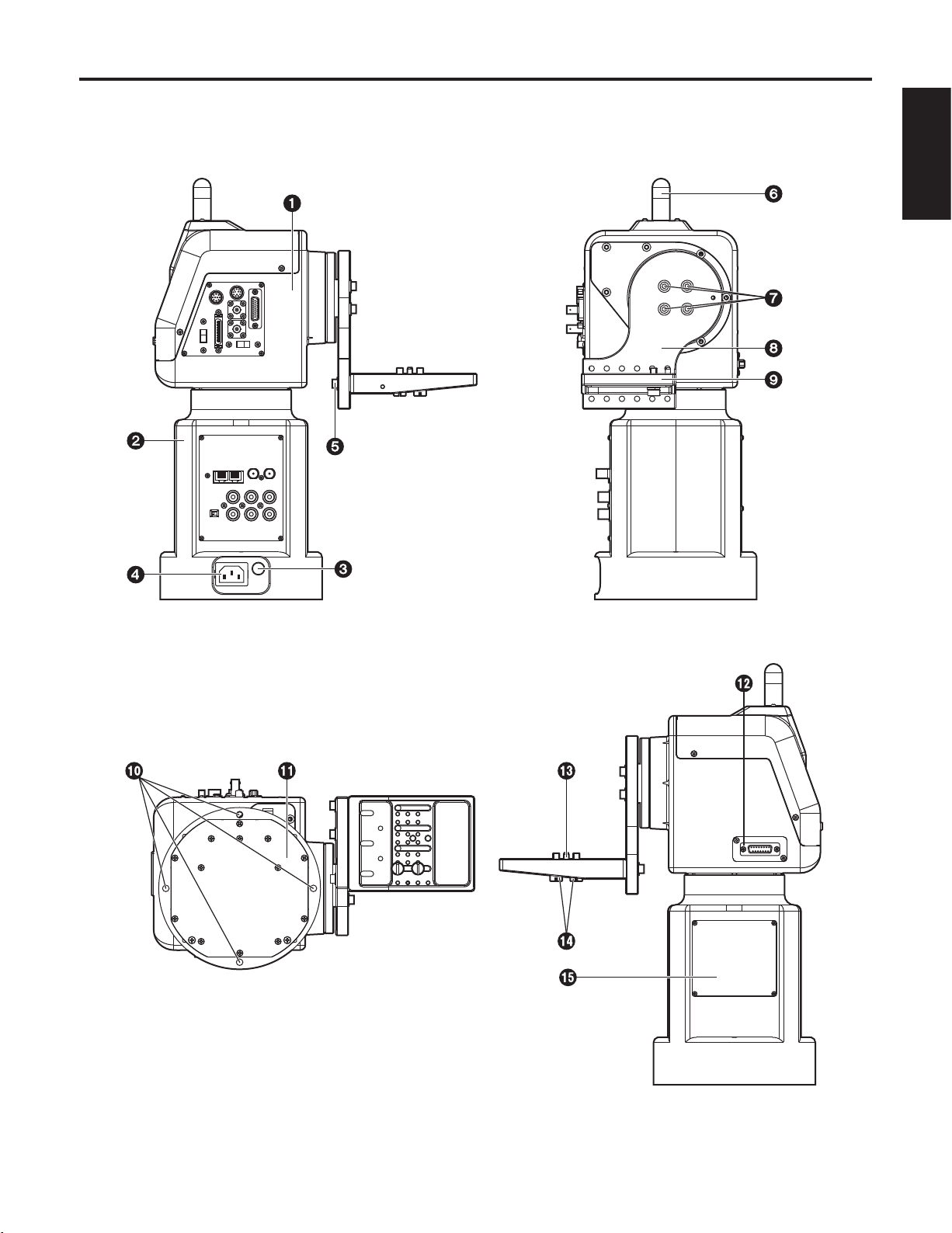
Rotary head
This rotates in the horizontal direction.
Pedestal
POWER ON/OFF switch
Where a switch is pushed in, the unit’s power is turned
on, and the unit’s power is turned off after the switch has
jumped out.
AC inlet [AC IN] (AC 3-point inlet)
Connect the accessory AC power cable to this inlet.
Camera mounting base mounting screws
M522 mm hexagon socket head screws (with flat
washers, spring washers) (3 of each provided as
accessories)
These parts are used to secure the camera mounting
base to the rotary arm.
Tally lamp (accessory)
This is lit up red by the selected signals.
Rotary arm mounting screws
M522 mm hexagon socket head screws (with flat
washers, spring washers) (4 of each provided as
accessories)
These parts are used to secure the rotary arm to the
rotary head.
Rotary arm
This rotates in the vertical direction.
Camera mounting base
Mount the convertible camera or multi-purpose camera
on this base.
Pan-tilt head mounting holes
These four holes are used when installing the pan-tilt
head.
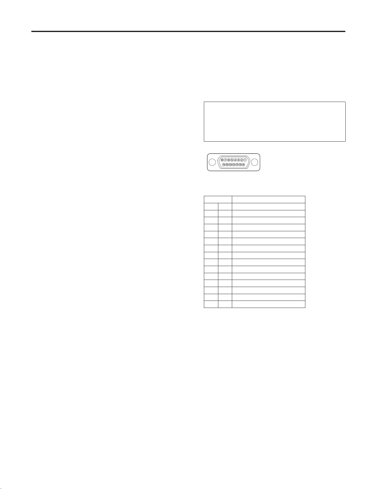
PROMPTER connector
The prompter is connected to this connector.
The maximum current which can be supplied from the DC
12 V OUT socket is 2.5 A.
When the prompter is connected, the pan-tilt head’s
speed is reduced to about one-third.
When connecting the prompter, be absolutely sure to
short-circuit the DETECT terminal (Pin No.14) and the
GND terminal (Pin No.15).
Note
Pin layout as seen facing
the prompter connector
Pin No. Signal Name
1 – – –
2 PROMPTER VIDEO
3 – – –
4 DC 12 V OUT
5 GND
6 – – –
7 – – –
8 – – –
Consult your dealer when a prompter is to
be installed since it will be necessary for
the balance between the mounting fixture
and overall weight and other aspects to be
checked.
9 – – –
10 PROMPTER VIDEO GND
11 – – –
12
13
14 DETECT
15 GND
– – –
– – –
Bottom panel
Use the unit with this panel in position.
Guide pin
Use this to determine the direction in which the camera is
to be mounted.
Camera mounting screws (U1/4” 20UNC)
These are used to secure the camera firmly after it has
been mounted.
Side blank panel
For normal operation, use the unit with this panel in
position.
7 (E)
Page 9
Parts and their function
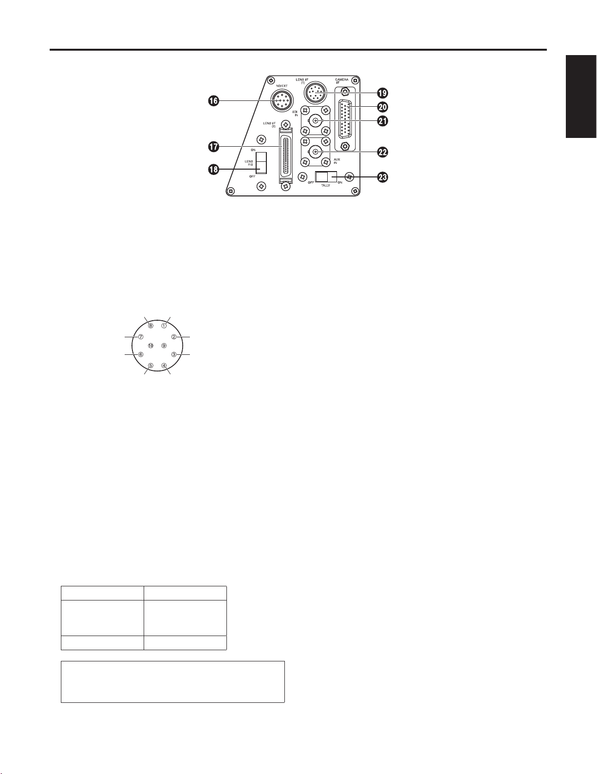
Rotary head connector panel
ENGLISH
ND/EXT connector [ND/EXT]
This is for the control of the ND filter and lens extender of
the motorized lens unit.
Connect this connector when using a motorized lens
unit with ND filter and lens extender functions. The cable
described in “Cable specifications” on page 25 is required
in order to connect this connector.
CVCC (12 V)CanonEXT ()
CanonEXT ()
ND Signal
(Pin layout as seen from cable end)
The current rating of the CVCC and CGND pins is
500 mA (max). Any devices whose maximum current
consumption exceeds 500 mA cannot beused.
CGND
EXT Return
EXT SignalND Return
LENS I/F (2) connector [LENS I/F (2)]
This is used when an IAS, WAS or VAS lens made by
Canon or an RD lens made by Fujinon is to be used.
The optional connecting cable is required to connect the
lens with the connector.
The current rating of LENS I/F (2) connector is 500 mA
(max).
The lens whose maximum current consumption exceeds
500 mA cannot be used. Concerning the maximum
current consumption of the lens, contact the lens
manufacturer.
Lens Cable
Canon
Digital
Analogue
Fujinon AW-CA4FLZG
AW-CA4DLZG
AW-CA4ALZG
LENS P/S ON/OFF switch [LENS P/S]
When this is set to ON, power is supplied to the lens from
the LENS I/F (1) connector. When it is set to OFF, power
is no longer supplied to the lens from the LENS I/F (1)
connector.
Set this switch to OFF when power is to be supplied from
a source outside the unit without using the AW-PH405’s
dedicated camera cable.
LENS I/F (1) connector [LENS I/F (1)]
This is used to control the zooming and focusing of the
motorized lens unit.
Use the motorized lens unit’s remote (zoom/focus) control
cable to make the connection.
CAMERA I/F connector [CAMERA I/F]
This is used for the control of the convertible camera.
Use the camera cable supplied with the AW-PH405 to
connect the connector with the REMOTE connector on
the camera.
Depending on the functions of the optional card, a special
camera cable (sold separately) is required.
SDI IN connector [SDI IN]
Use a coaxial cable to connect this to the SDI OUT
connector on the AW-PB504 SDI card or other card
installed in the convertible camera.
AUX IN connector [AUX IN]
This connector is connected using a BNC coaxial cable
to the SDI OUT connector on the AW-PB504 SDI card
or other card installed in the convertible camera or to the
VBS connector on the AK-HDC1500G down converter
board or other board installed in the AK-HC1500G
multi-purpose camera.
TALLY OFF/ON switch [TALLY]
When this is set to ON, the tally lamp is lit by the selected
signals. When it is set to OFF, the () tally lamp will not
light even if the selected signals are supplied.
Note
Refer to the instructions for using the
connecting cable to ensure that it is
connected properly.
8 (E)
Page 10
Parts and their function
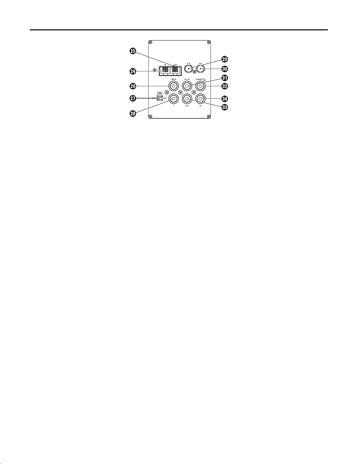
Pedestal connector panel
CONTROL IN RP connector [RP]
This is the connector for the control of signals of the
camera and pan-tilt head.
It is connected to the TO PAN/TILT HEAD connector on
the AW-RP655 multi-function controller and AW-RP555
multi hybrid control panel.
Use a 10BASE-T (equivalent to UTP category 5) straight
cable for the connecting cable.
COM connector [COM]
This is the connector for the control signals used to
extend the camera’s functions.
VIDEO connector [VIDEO]
This the output connector for the convertible camera’s
video signals.
It is connected to the Y/VIDEO connector on the
AW-RC400 cable compensation unit or monitor, etc.
Use a BNC coaxial cable for the connecting cable.
CABLE COMP OFF/ON switch [CABLE COMP]
When this is set to ON, signals which have been cable
compensated for the equivalent of 500 meters are
output from the VIDEO connector and the Y, Pr and Pb
connectors.
When this switch is used in conjunction with the
AW-RC400 cable compensation unit, the video cable can
be extended up to a maximum of 1000 meters.
AUX connector [AUX]
This is the output connector for the camera’s video
signals.
It enables the SDI signals, VBS signals, etc. from the
BNC coaxial cable connected to AUX IN to be output.
Provide a BNC coaxial cable as the connecting cable.
No cable compensation is provided for the signals which
are output from this connector.
SDI connector [SDI]
This is the output connector for the camera’s video
signals.
It enables the SDI signals, VBS signals, etc. from the
BNC coaxial cable connected to SDI IN to be output.
Provide a BNC coaxial cable as the connecting cable.
No cable compensation is provided for the signals which
are output from this connector.
G/L IN connector [G/L IN]
This is the genlock signal input connector.
It is connected to the G/L OUT connector on the
AW-RC400 cable compensation unit or other unit.
Use a BNC coaxial cable for the connecting cable.
PROMPTER IN connector [PROMPTER IN]
The video signals for the prompter are input to this
connector.
Use a BNC coaxial cable for the connecting cable.
Y connector [Y]
This is the output connector for the camera’s video
signals.
It is connected to the Y/VIDEO connector on the
AW-RC400 cable compensation unit or monitor, etc.
Use a BNC coaxial cable for the connecting cable.
Pr/C connector [Pr/C]
This is the output connector for the camera’s video
signals.
It is connected to the Pr/C connector on the AW-RC400
cable compensation unit or monitor, etc.
Use a BNC coaxial cable for the connecting cable.
Pb connector [Pb]
This is the output connector for the camera’s video
signals.
It is connected to the Pb connector on the AW-RC400
cable compensation unit or monitor, etc.
Use a BNC coaxial cable for the connecting cable.
9 (E)
Page 11
Installation
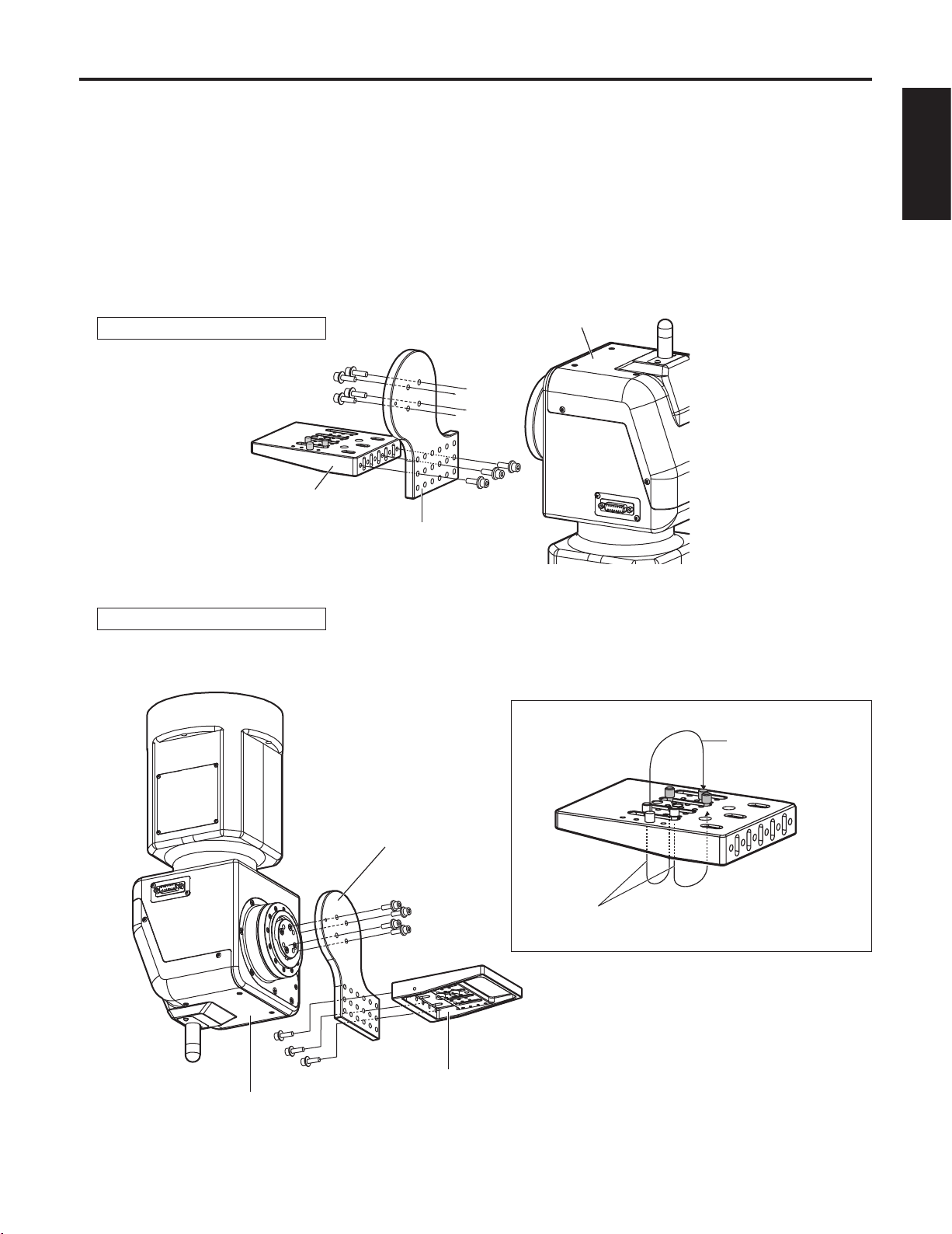
Assembling the pan-tilt head
When assembling the pan-tilt head, use the Allen key (provided) and screwdriver, and secure the head by tightening the screws
firmly. After mounting the pan-tilt head, check there is no play in its installation.
Attaching the camera mounting base
Attach the camera mounting base to the rotary arm using the three mounting screws (M522 mm, with flat washers, spring
washers) provided. The installation direction differs depending on how the base is installed.
Attaching the rotary arm
Attach the rotary arm to the rotary head using the four mounting screws (M522 mm, with flat washers, spring washers)
provided. The installation direction differs depending on how the arm is installed.
ENGLISH
For a stand-alone installation
Rotary head
Camera mounting base
Rotary arm
For installation on the ceiling
Change the guide pin and screw positions as shown in the figure below on the right, and then attach the camera mounting
base to the rotary arm.
Camera Mounting base
Change the positions
of the guide pins.
Rotary head
Rotary arm
Change the positions of the
camera mounting screws.
Camera mounting base
10 (E)
Page 12
Installation
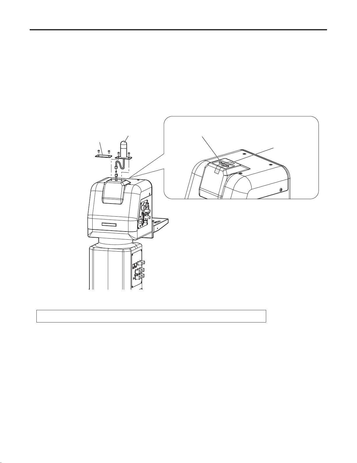
Mounting the tally lamp
Connect the cable connector which is taped to the top of the pan-tilt head to the tally cable connector.
Mount the tally lamp on the top of the pan-tilt head using the two screws provided.
Mount the lamp while paying attention to the wire.
The cable for the tally cable connector is about 50 mm long.
When connecting the cable to the connector, do not pull it out beyond this length.
If the tally lamp is not going to be used, insert the cable which is stuck to the top of the pan-tilt head inside the pan-tilt head,
and attach the blank panel for the tally lamp using the two screws provided.
Blank panel
Tally lamp
Tally cable connector
Taped
Note
Tighten up the screws securely to ensure that they will not come loose during use.
11 (E)
Page 13

Installation
Concerning the safety modes
This unit comes with two safety modes which are designed to safeguard the user and others from injury and to prevent damage
to the pan-tilt head.
1. Mode for ensuring safety in the case of collisions
When the rotary arm of the pan-tilt head or some other unit installed on the head keeps colliding with an obstruction or a
person (approx. 6 seconds when the head rotates at 45 degrees per second), the mode for ensuring safety in the case of
collisions is established.
In this mode, only the rotation of the head in the direction of the collision is stopped.
In the case of a low-speed collision, it will take longer for the safety mode to be established.
<Procedure for restoration from the safety mode>
The mode for ensuring safety in the case of collisions is released by bringing the joystick of the pan-tilt head controller
(such as the AW-RP655) back to its centre position.
A poor weight balance may cause the mode for ensuring safety in the case of collisions to be established.
Depending on the prevailing conditions, it may be necessary to adjust the balance, in which case consult your dealer.
2. Mode for ensuring safety in the case of trouble
When the pan-tilt head has detected trouble, the mode for ensuring safety in the case of trouble is established.
In this mode, the up/down and left/right rotation of the head is stopped.
<Procedure for restoration from the safety mode>
The mode for ensuring safety in the case of trouble is released by first pressing the POWER ON/OFF switch to turn off the
power and then by pressing the switch again to turn the power back on.
If the mode for ensuring safety in the case of trouble is established frequently, it may mean that the pan-tilt head is
malfunctioning. Consult your dealer.
ENGLISH
12 (E)
Page 14

Installation
Procedure for changing the settings of the CPU circuit board switches
Follow the steps below to change the settings of the CPU circuit board switches.
Remove the four screws, and gently remove the housing case.
Disconnect the tally cable connector.
Set the switches on the CPU circuit board.
After you have performed the settings, connect the tally cable connector, and then return the housing case to its original
position, and attach it using the screws. (Take care to ensure that the wiring is not pinched.)
Four screws
Note
Tally cable connector
Housing case
Magnification of the CPU circuit board
Be absolutely sure to turn off the power before changing the position of this switch.
13 (E)
Page 15
Installation
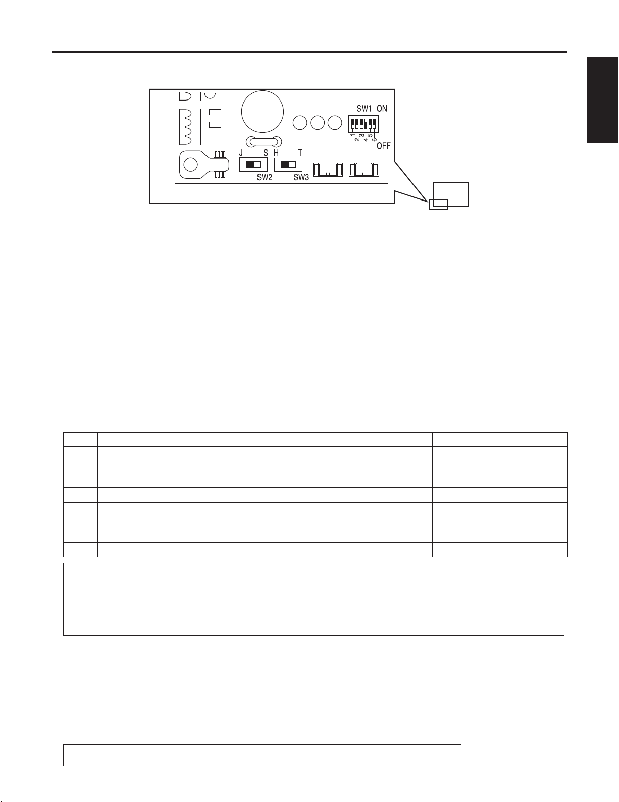
Setting the CPU circuit board switches
CPU circuit board
Magnification of the CPU circuit board
Setting SW1
These switches are used to set the operations of the AW-PH405. Before changing their settings, make sure that the power
has been turned off.
No.1: Auto focus (AF)/extender (EXT) selector switch.
Use this at the ON position when using an auto focus lens which is connected to the LENS I/F (1) connector; use it
at the OFF position when using a lens with a motorized extender connected to the ND/EXT connector.
No.2: Diagonal operation selector switch. Set this to ON to use the diagonal operation capability; set this to OFF to stop
using the diagonal operation capability.
The DIAGONAL MOTION menu setting can be changed from the AW-RP655 or other controller only when the
diagonal operation selector switch is at the ON position.
No.3: Tilt range selector switch. The tilt range is 300 degrees at ON and 190 degrees at OFF.
Settings can be changed from a personal computer or other external device only when the tilt range selector switch
is at the ON position.
No.4: Zoom offset automatic compensation switch of the lens which is connected to the LENS I/F (2) connector. This is
normally kept at the ON position for use.
Use this switch at the OFF position when zooming manually using the zoom seesaw switch of the lens.
When the zoom offset automatic compensation selector switch of the lens is set to ON, the zoom position will be
automatically compensated. For this reason, the zoom seesaw switch of the lens cannot be used to control the
zoom in the desired manner.
No.5, 6: These switches are not used. Do not change their factory settings.
ENGLISH
No. Functions ON OFF
No.1
Auto focus (AF)/extender (EXT) selector
No.2
Diagonal operation ON/OFF selector
No.3
Tilt range 300 degrees/190 degrees selector
Zoom offset automatic compensation ON/OFF
No.4
switching
No.5 Not used (used by the service technician) – (factory settings)
No.6 Not used (used by the service technician) – (factory settings)
The diagonal operation capability:
ON (factory settings)
300° (factory settings) 190°
Automatic compensation: ON
AF EXT (factory settings)
The diagonal operation capability:
(factory settings)
Automatic compensation: OFF
OFF
Concerning the zoom offset automatic compensation function
In the case of a lens which does not detect the control voltage used by the pan-tilt head to stop the zooming, a
difference in potential from the pan-tilt head side may arise, causing the zoom position to shift even when zoom control
is not exercised from the pan-tilt head controller (such as the AW-RP655). To prevent this phenomenon from occurring,
the zoom offset automatic compensation function works to automatically compensate the control voltage used by the
pan-tilt head to stop the zooming.
Setting the landing characteristics
When changing the landing characteristics, set the switch as follows:
Soft landing: Set SW2 to its right position (S). (factory settings)
Just landing: Set SW2 to its left position (J).
Setting the installation direction switch
For a ceiling installation, set the switch as follows:
Stand-alone installation: Set SW3 to its right position (T). (factory settings)
Installation on the ceiling: Set SW3 to its left position (H).
Note
Be absolutely sure to turn off the power before changing the position of this switch.
14 (E)
Page 16

Installation
Pan-tilt head mounting conditions
Pan-tilt
head weight
Approx. 10 kg
Mounting
specifications
Stand-alone
installation or
installation on
the celling
Compatible
cameras
Convertible
camera series
AW-E350
AW-E650
AW-E655
AW-E750
AW-E860
Multi-purpose
camera series
AK-HC1500G
Mounting the pan-tilt head
Recommended screws No. of screws
M6 screws (hexagonal nuts) 4 pcs
Notes
Refer to the above table for the total weight of the pan-tilt head with the camera, lens, cables and any
other accessories installed.
Install the equipment on an installation surface which is capable of ensuring a drop safety equivalent to
five times the figure for the total weight.
The maximum weight of the units which can be installed on the pan-tilt head is 15 kg or so (or
approximately 25 kg total for the weight of the pan-tilt head and weight of the units installed on the
head). When mounting the pan-tilt head on which units have been installed, be sure to mount it on an
installation surface which is itself capable of ensuring a satisfactory drop safety.
Camera
weight
Approx.
1.2 kg max.
Approx.
1.5 kg
Camera
anti-drop
measures
Wire provided
used for
mounting
Compatible
lenses
AW-LZ16MD55P
AW-LZ16MD73P
AW-LZ17MD9AG
HA21 series
HA22 series
HJ17e series
HJ21e series
Lens weight
Approx. 1.3 kg
Approx. 3.2 kg
max.
max.
Cable
weight
Approx. 0.3 kg
Total weight
Approx. 13 kg
Approx. 15 kg
Installing the pan-tilt head
Before installing the pan-tilt head, check that the above mounting conditions are satisfied, and observe the following precautions.
In order to prevent accidents resulting when the product becomes dislodged or falls down, be absolutely sure to proceed as
instructed. Do not install the pan-tilt head on its side since its prescribed operation and performance cannot be ensured.
After the pan-tilt head has been installed, mount the camera on it.
When installing the pan-tilt head, use the four mounting holes to secure the pan-tilt head firmly.
Ensure that the surface on which the pan-tilt head will be installed and the anchor bolts used are sufficiently strong.
Use the M6 hexagon head bolts (including one short bolt) for installation.
Use hexagon head bolts which are longer than the thickness (t) of the mounted member 25 mm.
As shown in the figure of next page, use flat washers, spring washers and hexagon nuts for the hexagon head bolts.
Use a wrench of the appropriate size to tighten up the hexagon head bolts.
Provide a wire which is strong enough to support the combined weight of the entire pan-tilt head system (which consists of the
pan-tilt head, camera, lens and cable).
Do not use a surface made of plaster board or wood as this kind of installation surface will not be strong enough. If mounting
on such a surface is unavoidable, take sufficient anti-drop measures.
Install the pan-tilt head in such a way that the equipment and cable attached to it will not make contact with any surrounding
objects when the head is swiveled.
When the unit is no longer going to be used, do not leave it in place, and be absolutely sure to remove it.
15 (E)
Page 17

Installation
For a stand-alone installation For installation on the ceiling
ENGLISH
Note
When installing the pan-tilt head, do not forcibly turn the rotary head or rotary arm
manually. Doing so may result in malfunctioning.
16 (E)
Page 18

Installation
Mounting the camera
[Convertible camera AW-E350/E650/E655/E750/E860]
When mounting the camera, take sufficient care to ensure that the camera will not come off or fall down.
Mount the lens onto the convertible camera.
(Before mounting a large lens, consult with your dealer.)
Mount the convertible camera after aligning it with the guide pins.
Use a tool to tighten up the mounting screws so that they are securely tightened.
For a stand-alone installation
Set the guide pin.
Mount the camera with the
mounting screws.
Mounting screws
For installation on the ceiling
<Recommended lenses>
Camera Lens
AW-E350
AW-E650
AW-E655
AW-E750
AW-E860
AW-LZ16MD55P
AW-LZ10MD6
AW-LZ16MD73P
AW-LZ16AF7G
AW-LZ17MD9AG
Set the guide pin.
Mount the camera with
the mounting screws.
Mounting screws
Be absolutely sure to use a screwdriver or other tool to tighten the two camera mounting screws
so that the camera is secured firmly.
After the camera has been mounted, check that there is no play in the way it was mounted.
17 (E)
Page 19

Installation
Attaching the wire
[Convertible camera AW-E350/E650/E655/E750/E860]
The camera comes with a wire for preventing the camera from dropping. Follow the instructions below to use it to couple the
camera to the pan-tilt head.
When mounting the cameras with fan (AW-E655, AW-E750, AW-E860)
Use the wire mounting screw (M48 mm with flat washer and spring washer) to attach one end of the wire to the pan-tilt
head’s arm.
Mount the mounting spacer on the top panel of the camera. (The mounting spacer is provided with the camera as an accessory.)
Use the wire mounting screw (M48 mm with flat washer and spring washer) to attach the other end of the wire to the screw
hole of the mounting spacer.
When mounting the cameras without fan (AW-E350, AW-E650)
Use the wire mounting screw (M48 mm with flat washer and spring washer) to attach one end of the wire to the pan-tilt
head’s arm.
Use the wire mounting screw (M48 mm with flat washer and spring washer) to attach the other end of the wire to the screw
hole of the top panel of the camera.
ENGLISH
For a stand-alone installation
Camera: AW-E750
M48 mm wire
mounting screw
with flat washer
and spring washer
Mounting spacer
( supplied with
AW-E750)
Wire
M48 mm wire
mounting screw
with flat washer
and spring washer
Arm
For installation on the ceiling
Camera: AW-E750
Camera: AW-E350, AW-E650 Camera: AW-E350, AW-E650
M48 mm wire
mounting screw
with flat washer and
spring washer
M48 mm
wire mounting
screw with flat
washer and
spring washer
Mounting spacer
( supplied with
AW-E750)
Be absolutely sure to tighten up the mounting spacer and screws securely using a tool such as a screwdriver.
18 (E)
Page 20

Installation
Mounting the camera
[Multi-purpose camera AK-HC1500G]
When mounting the camera, take sufficient care to ensure that the camera will not come off or fall down.
Mount the lens onto the multi-purpose camera.
(1) Lenses that can be used
• Use any of the portable lenses which are listed below.
Fujinon HA18, HA21, HA22 series
Canon HJ17e, HJ21e series
(2) Lenses that cannot be used
• Do not use the large-sized lenses (with a weight of 5 kg or more
and a length of 400 mm or more) with the model numbers which
are listed below since when they are mounted on the camera,
the camera’s overall balance will be upset.
Fujinon HA42 series
Canon HJ40 series, J35 series
Align the multi-purpose camera with the guide pins and mount it.
Change the positions of the guide pins and screws of the camera mounting base as shown in the figure below, and then
attach the camera mounting base to the rotary arm.
Do not use the rubber piece.
Note
The current rating of LENS
I/F (2) connector is 500 mA
(max).
Even with the lenses in a
series which can be used,
any lens whose maximum
current consumption
exceeds 500 mA cannot be
used.
Concerning the maximum
current consumption of
the lens, contact the lens
manufacturer.
For a stand-alone installation
Camera Mounting base
Change the positions
of the guide pins.
Change the positions of the camera mounting
screws. (Change them over to the second row.)
Tighten up the two mounting screws securely using the tool.
For installation on the ceiling
Camera Mounting base
Change the positions
of the guide pins.
Set the guide pin.
Mount the camera
with the mounting
screws.
Mounting screws
Set the guide pin.
Mount the camera with
the mounting screws.
Change the positions of the camera mounting
screws. (Change them over to the third row.)
Just as for a convertible camera, change the positions of the guide pins and screws of the camera mounting base as shown
in the figure above, and then attach the camera mounting base to the rotary arm.
Mounting screws
19 (E)
Page 21

Installation
Concerning the balance of the installed unit
The weight balance may be impaired when the pan-tilt head is used in combination with a camera and long lens.
Follow steps to below to check the balance, and then mount the camera. If, after this, the balance is still impaired and
operations cannot be performed smoothly, it means that the balance must be adjusted. Consult your dealer.
How to obtain the balance
Check the centre of gravity position with the camera and lens set up on the pan-tilt head.
Position where the balance between left and
right is attained (centre of gravity)
The less the deviation between the centre of gravity position and the head’s centre of rotation, the more the balance is
attained. Check these positions when mounting the pan-tilt head.
ENGLISH
Head’s centre of rotation
Deviation between centre of gravity position
and the head’s centre of rotation
If the proper balance cannot be attained in steps and , re-attach the camera mounting base and rotary arm to shift the
position of the entire camera so that the centre of gravity position is brought closer to the head’s centre of rotation.
When doing this, bear in mind the following points.
(1) Depending on the specifications of the lens and its installation direction, the protruding parts of the lens or grip area may
come into contact with the rotary arm or other parts, in which case do not re-attach the camera mounting base and rotary
arm.
(2) If the protrusion of the connectors from the camera makes contact with the mounting surface of the pan-tilt head, insert a
spacer as described on the next page between the pan-tilt head and mounting surface or set the limiters.
(3) Be absolutely sure to secure the camera mounting base and rotary arm firmly using the three screws.
Centre of gravity position with camera and
lens set up
Head’s centre of rotation
Camera mounting base
Re-attach the camera
mounting base to a
position further back.
Rotary arm
Minimize the deviation between
the centre of gravity position
and the head’s centre of
rotation here.
20 (E)
Centre of gravity position
with camera and lens set up
Page 22

Installation
Precautions for mounting the camera
Bearing in mind the length of the lens, set the movement range of the pan-tilt head using the limiters in such a way that the
hood at the edge of the lens will not come into contact with the surface on which the pan-tilt head is installed when the pan-tilt
head is tilted.
Note
To point the lens any further straight down in a
stand-alone installation, insert a spacer between
the pan-tilt head and mounting surface to raise the
pan-tilt head position.
Make sure that the spacer has a strong enough
construction. Also ensure that the mounting bolts
used are long enough.
Spacer
Lens must not come into contact with
mounting surface.
When the pan-tilt head is installed on the ceiling, contact with the pan-tilt head body may be made by the protrusion of the
drive unit when tilting operations are performed. For this reason, set the limiters before proceeding with the installation work.
Protrusion of drive unit
must not come into contact
with pan-tilt head body.
Do not tie the connected lens cable and camera cable together as a bundle. During operation, excessive strain may be placed
on cables which have been bundled together. Instead, be absolutely sure to tie them separately.
Be absolutely sure to use a screwdriver or other tool to tighten the two camera mounting screws
so that the camera is secured firmly.
After the camera has been mounted, check that there is no play in the way it was mounted.
21 (E)
Page 23

Installation
Attaching the wire
[Multi-purpose camera AK-HC1500G]
The camera comes with a wire for preventing the camera from dropping. Follow the instructions below to use it to couple the
camera to the pan-tilt head.
Use the wire mounting screw (M48 mm with flat washer and spring washer) to attach one end of the wire to the pan-tilt
head’s arm.
Use the wire mounting screw (Inch screw with flat washer and spring washer) to attach the other end of the wire on the top
panel of the camera.
ENGLISH
For a stand-alone installation
Camera: AK-HC1500G
Wire mounting
screw (Inch
screw with flat
washer and
spring washer)
M48 mm wire
mounting screw with
flat washer and spring
washer
Wire
Arm
For installation on the ceiling
Camera: AK-HC1500G
M48 mm wire mounting
screw with flat washer and
spring washer
Wire mounting
screw (Inch screw
with flat washer and
spring washer)
Be absolutely sure to tighten up the screws securely using a tool such as a screwdriver.
22 (E)
Page 24

Connections
Turn off the power of all the equipment before proceeding with the connections.
Connect the AC power cable supplied with the AW-PH405 for the AW-PH405 indoor pan-tilt head.
Use 10BASE-T straight cables to connect the RP connectors on the pan-tilt heads with the CONTROL OUT TO PAN/TILT
HEAD (1 to 5) connectors on the AW-RP655 multi-function controller and AW-RP555 multi hybrid control panel. The maximum
extension distance is 1000 meters when using UTP category 5 cables or their equivalent.
Use the camera cables supplied with the pan-tilt head to connect the AW-PH405 to the convertible camera.
Connect the iris control cable of the motorized zoom lens to the IRIS connector on the camera, and connect the zoom/focus
cable to the LENS I/F (1) connector on the pan-tilt head.
For a convertible camera
Motorized zoom lens Iris control cable
To the
10BASE-T
straight cable
LENS I/F (1)
connector
AW-PH405
Indoor Pan-tilt Head
Pan-tilt head/camera control signals
Zoom/focus
control cable
Camera cable
supplied with
AW-PH405
AW-RP655
Multi-function controller
AW-CB400
Remote operation
panel
AW-RP555
Multi Hybrid Control Panel
AW-RP400
Pan-tilt control panel
AW-PS505A
AC adapter
AW-PS505A
AC adapter
Convertible camera
BNC cable video signal
AC power cable
supplied with
AW-PH405
Monitor
• AW-IF400
Switch settings
SW1 SW2
ON ON OFF OFF OFF OFF
AW-IF400
Protocol converter
SET UP
1 2 3 4
23 (E)
AW-PS505A
AC adapter
AW-PS505A
AC adapter
Page 25

Connections
For the AK-HC1500G
Note
10BASE-T
straight cable
Set the menu items to protocol 4.
Pan-tilt head/camera control signals
AW-RP555
Multi Hybrid Control Panel
Motorized zoom lens Iris control cable
To the
LENS I/F (1)
connector
AW-PH405
Indoor Pan-tilt Head
AW-PS505A
AC adapter
Zoom/focus
control cable
HD SDI video signal
ENGLISH
Camera cable
AW-CA15H29G
AC power cable
supplied with
AW-PH405
• AW-IF400
AW-RP655
Multi-function controller
AW-RP400
Pan-tilt control panel
AW-CB400
Remote operation
panel
AW-PS505A
AC adapter
AW-PS505A
AC adapter
Use the connecting cables below to connect the pan-tilt head and camera.
AW-CA15H29G
Refer to the operating instructions for using the connecting cable to ensure that it is connected properly.
Switch settings
SW1 SW2
ON ON OFF OFF OFF OFF
AW-IF400
Protocol converter
Monitor
SET UP
1 2 3 4
AW-PS505A
AC adapter
24 (E)
Page 26

Cable specifications
When connecting a Canon lens with motorized extender unit
Connector: HR10A-10P-10P (73)
made by Hirose Electric
CVCC (12 V)
CGND
EXT Return
EXT Signal
ND Return
ND Signal
CanonEXT ()
CanonEXT ()
GND
GND
SHELL
Connect this connector to the ND/EXT
connector on the pan-tilt head
When connecting a Fujinon extender change unit
Connector: HR10A-7P-6S (73)
made by Hirose Electric
SHELL
Connect this connector
to the EXT connector on
the lens
Connector: HR10A-10P-10P (73)
Connector: HR10A-7P-5P (73)
made by Hirose Electric
CVCC (12 V)
CGND
EXT Return
EXT Signal
ND Return
ND Signal
CanonEXT ()
CanonEXT ()
GND
GND
SHELL
Connect this connector to the ND/EXT
connector on the pan-tilt head
SHELL
Connect this connector
to the 5-pin connector on
the extender change unit
For details on how to connect the extender change unit to the lens, consult the information
provided by the manufacturer of the lens.
made by Hirose Electric
25 (E)
Page 27

Replacing the consumable parts
Replacing the motor
Replace the motor when it ceases to operate properly.
For details on the motor replacement, consult your dealer.
Replacing the belt
Replace the belt when the preset stop accuracy has deteriorated.
For details on the belt replacement, consult your dealer.
Replacing the gear
Replace the gear when the preset stop accuracy has deteriorated.
For details on the gear replacement, consult your dealer.
ENGLISH
The motor, gear and belt are consumables.
They need to be replaced at periodic intervals.
As a general guideline, replace them when the cumulative
total time for all the rotation operations reaches 3,000 hours.
26 (E)
Page 28

Appearance
Unit: mm
319
137 182
ø146
71
97
ø160
168
42
165209
416
47
ø160
ø146
ø160
<Mounting hole specifications>
27 (E)
4-M6 screws
Page 29

Specifications
Supply voltage: AC 220 to 240 V, 50 Hz
Power consumption: 120 W
indicates safety information.
Genlock input: BNC
Black burst or composite video signal, Tri Sync
Prompter input
(PROMPTER IN): BNC
Prompter output
(PROMPTER OUT): D-SUB 15-pin
Camera video output
VIDEO: BNC, 75-ohm output
Y: BNC, 75-ohm output
Pr/C: BNC, 75-ohm output
Pb: BNC, 75-ohm output
SDI: BNC
AUX: BNC
Camera, pan-tilt head control: RJ45, RS-422, pan-tilt head control signal output
RP Connecting cable: 10BASE-T straight cable (equivalent to UTP category 5),
Functions/performance: Maximum weight capacity: 15 kg
Pan range: 300 degrees (approx. ±150 degrees)
(Maximum operating speed with prompter mounted: 15 degrees/sec.)
Stop accuracy: ±3´
Through output to PROMPTER connector
max. 1000 meters
Tilt range: 300 degrees (approx. ±150 degrees)
The tilt range is subject to restrictions depending on the cable and lens of camera to be
mounted on pan-tilt head.
Maximum operating speed: 45 degrees/sec.
( when the centre of gravity of the units installed on the pan-tilt head has been aligned with
the head’s centre of rotation)
Noise level: Less than NC35 (at less than 30 degrees/sec.)
ENGLISH
Ambient operating temperature: –5°C to +45°C
Storage temperature: –20°C to +65°C
Ambient operating humidity: 30% to 90% (no condensation)
Dimensions (WHD): 319416168 mm
Weight: Approx. 10 kg
Finish: AV ivory paint (colour resembling Munsell 7.9Y6.8/0.8)
Weight and Dimensions indicated above are approximate.
Specifications are subject to change without notice.
28 (E)
Page 30

РУССКАЯ ВЕРСИЯ
(RUSSIAN VERSION)
Меры предосторожности
НЕ ОТВИНЧИВАЙТЕ КРЫШКИ ПАНЕЛЕЙ.
Для снижения риска удара электрическим током не снимайте
панели. Внутри устройства нет деталей, подлежащих
обслуживанию пользователем.
Обратитесь за сервисным обслуживанием к
квалифицированному персоналу.
ОСТОРОЖНО:
ДЛЯ СНИЖЕНИЯ РИСКА ВОЗНИКНОВЕНИЯ ПОЖАРА ИЛИ
УДАРА ЭЛЕКТРИЧЕСКИМ ТОКОМ И ВОЗНИКНОВЕНИЯ
ПОМЕХ ИСПОЛЬЗУЙТЕ ТОЛЬКО РЕКОМЕНДУЕМЫЕ
ДОПОЛНИТЕЛЬНЫЕ ПРИНАДЛЕЖНОСТИ.
ВНИМАНИЕ:
•
ДЛЯ СНИЖ ЕНИЯ РИС КА ВОЗН ИКНОВ ЕНИЯ ПОЖАРА
ИЛИ УДАРА ЭЛЕКТРИЧЕСКИМ ТОКОМ НЕ ПОДВЕРГАЙТЕ
ДАННОЕ ОБОРУДОВАНИЕ ВОЗДЕЙСТВИЮ ДОЖДЯ ИЛИ
ВЛАГИ.
•
НЕ ПОДВЕРГАЙТЕ АППАРАТ ВОЗДЕЙСТВИЮ КАПЕЛЬ ИЛИ
БРЫЗГ ЖИДКОСТЕЙ; ТАКЖЕ НЕ СТАВЬТЕ НА АППАРАТ
КАКИЕ-ЛИБО ЕМКОСТИ, НАПОЛНЕННЫЕ ЖИДКОСТЬЮ,
ТАКИЕ КАК ВАЗЫ.
ВНИМАНИЕ:
ВО ИЗБЕЖАНИЕ ПОВРЕЖДЕНИЯ ДАННЫЙ ПРИБОР
ДОЛЖЕН БЫТЬ НАДЕЖНО ЗАКРЕПЛЕН НА ПОЛУ/
СТЕНЕ В СООТВЕТСТВИИ С ИНСТРУКЦИЕЙ ПО
УСТАНОВКЕ.
ОСТОРОЖНО:
ДЛЯ СНИЖЕНИЯ РИСКА ПОЖАРА ИЛИ ПОРАЖЕНИЯ ТОКОМ
ИЗМЕНЕНИЯ РЕГУЛИРОВКИ ВЫКЛЮЧАТЕЛЯ ВНУТРИ
ДОЛЖНЫ ПРОИЗВОДИТЬСЯ КВАЛИФИЦИРОВАННЫМ
СЕРВИСНЫМ ПЕРСОНАЛОМ.
ОСТОРОЖНО:
Для обеспечения надлежащей вентиляции не
устанавливайте и не размещайте данное устройство на
книжном стеллаже, во встроенном шкафу или в другом
закрытом пространстве. Для предотвращения риска
поражения электрическим током или опасности возгорания
вследствие перегрева убедитесь, что занавески или другие
материалы не препятствуют вентиляции.
Сетевaя штепcельнaя вилкa или пpибopный coединитель
дoлжны ocтaвaтьcя гoтoвыми к paбoте.
Имейте в виду, что аппарат, относящийся по конструкции к
КЛАССУ 1, следует подключать к СЕТЕВОЙ розетке с защитным
заземлением.
Данный знак обозначает информацию,
относящуюся к технике безопасности.
1 (R)
Page 31

Информация для пользователей по утилизации электрического и электронного оборудования
(бытового использования)
Данный символ на изделиях и/или сопутствующих документах означает, что применяемые электрические и
электронные изделия не следует выбрасывать вместе с остальными бытовыми отходами.
Для проведения надлежащего ухода, восстановления и утилизации, пожалуйста, доставьте данные устройства
в обозначенные пункты приема, где они будут приняты бесплатно. Кроме того, в некоторых странах у Вас может
быть возможность вернуть Ваши изделия местному распространителю в счет приобретения эквивалентного нового
изделия.
Правильная утилизация данного изделия поможет в сохранении ценных ресурсов и предотвратит любое возможное
отрицательное влияние на здоровья человека и состояние окружающей среды, которое могло бы возникнуть при неправильном
обращении с отходами.
Для получения подробной информации о ближайшей к вам точке сбора утиля, пожалуйста, свяжитесь с местными властями.
В соответствии с национальным законодательством за неправильную утилизацию данного изделия может быть назначен штраф.
Для бизнес-пользователей Европейского союза
Если Вы хотите утилизировать электрическое и электронное оборудование, для получения дополнительной информации,
пожалуйста, свяжитесь с Вашим дилером или поставщиком.
Информация по утилизации в других странах за пределами Европейского союза
Данный символ имеет силу только в Европейском союзе.
Если Вы хотите утилизировать данное изделие, пожалуйста, свяжитесь с Вашими местными властями или дилером и узнайте
корректный способ утилизации.
2 (R)
РУССКИЙ
Page 32

Содержание
Меры предосторожности ................................................................................................................................... 1
Меры предосторожности во время использования ..................................................................................... 4
Введение ............................................................................................................................................................... 4
Принадлежности .................................................................................................................................................. 5
Предосторожности по установке ..................................................................................................................... 5
Компоненты и их функции ................................................................................................................................ 6
Установка ............................................................................................................................................................ 10
Сборка наклонно-поворотной головки ...................................................................................................... 10
Режимы безопасности устройства ............................................................................................................. 12
Процедура изменения установки переключателей платы ЦПУ .............................................................. 13
Установка переключателей на плате ЦПУ ................................................................................................ 14
Условия крепления наклонно-поворотной головки .................................................................................. 15
Монтаж наклонно-поворотной головки ...................................................................................................... 15
Установка камеры (Съемная камера AW-E350/E650/E655/E750/E860) .................................................. 17
Присоединение троса (Съемная камера AW-E350/E650/E655/E750/E860) ........................................... 18
Установка камеры (Многоцелевая камера серии AK-HC1500G) ............................................................. 19
Сведения о балансировке установленного оборудования ...................................................................... 20
Присоединение троса (Многоцелевая камера серии AK-HC1500G) ....................................................... 22
Соединения ........................................................................................................................................................ 23
Технические характеристики кабеля ............................................................................................................. 25
Замена изнашиваемых деталей ..................................................................................................................... 26
Внешний вид ...................................................................................................................................................... 27
Технические характеристики ........................................................................................................................... 28
3 (R)
Page 33

Меры предосторожности во время использования
Соблюдайте меры безопасности при
транспортировке устройств.
При падении или при сильном ударе устройств может
произойти нарушение их работоспособности или
возникновение аварийных ситуаций.
Выключайте питание перед соединением или
отсоединением кабелей.
Перед соединением или отсоединением кабелей
обязательно убедитесь в том, что питание выключено.
Установите устройство возле сетевой розетки
питания и расположите его таким образом,
чтобы вилка питания легко вставлялась в
Не используйте устройства вне помещения.
Техобслуживание
Протирайте устройство сухой тряпкой. Для удаления
несмываемой грязи смочите тряпку в разбавленном
растворе кухонного чистящего средства, тщательно
отожмите ее и аккуратно протрите устройство.
<Осторожно>
Не используйте бензин, растворители красок и
другие легкоиспаряющиеся жидкости.
При необходимости использования материалов
химической очистки внимательно ознакомьтесь с
инструкцией по их применению.
розетку и вынималась из нее.
Введение
Автономная внутренняя наклонно-поворотная головка может поворачиваться на 300 градусов в вертикальном
направлении и на 300 градусов в горизонтальном направлении.
Повороты могут выполняться с максимальной скоростью до 45 градусов в секунду.
На наклонно-поворотной головке могут крепиться такие устройства, как камера с объективом, суммарным весом до 15 кг.
В предварительной памяти данных можно записать до 50 позиций положения камеры.
При использовании AW-IF400 для подключения AW-RP400 к устройству
• Невозможно использовать функцию трассировки памяти.
• Нельзя задать диапазон углов наклона TILT RANGE.
• Невозможно установить значение параметра MEMORY LENGTH.
• Нельзя задать значения ON или OFF для параметра DIAGONAL MOTION.
• Невозможна компенсация люфта.
• При переключении значения ON/OFF автофокуса (AF) и экстендера (EXT) через AW-RP400, используйте
OPTION SW после присвоения ему функции “EXT”.
При использовании объективов IAS, WAS или VAS производства Canon, объектива RD производства Fujinon
• Связь с контроллером наклонно-поворотной головки (например, AW-RP655) начинается сразу после
включения AW-PH405. Аналогично, процесс инициализации объектива начинается при включении питания
камеры. В процессе инициализации увеличение устанавливается автоматически и невозможно выполнение
функций управления контроллером наклонно-поворотной головки (например, AW-RP655).
• По завершении процесса инициализации не следует производить настройку регулятора скорости увеличения
объектива. Для регулировки этой скорости, сначала отключите питание AW-PH405, а затем продолжайте
процесс настройки.
• При положении ON переключателя автоматической компенсации изменения увеличения производится
автоматическая компенсация параметра увеличения. Поэтому невозможно правильное использование
самовозвратного регулятора увеличения объектива.
• После смены объектива камеры следует повторно выполнить функции настройки и трассировки памяти. Если
сохранить исходные настройки этих функций, увеличение объектива будет работать неправильно.
Примечания
Устройство AW-PH405 не может управляться от контроллеров AW-RP301, AW-RP305, AW-RP501, AW-RP505.
Не допускается применение устройства поворота камеры AW-RL400.
Нагрузка по току разъема LENS I/F (2) составляет 500 мА (макс.).
Не допускается использовать объективы, максимальная нагрузка по току которых превышает 500 мА.
Информацию о максимальном потреблении тока можно получить у производителя объектива.
В целях защиты окружающей среды при отбраковке
наклонно-поворотного устройства по завершении срока его службы обратитесь в
специализированную организацию в целях правильной утилизации.
Для некоторых объективов, установленных на камере, фокусировки и другие операции могут
выполняться в противоположном направлении.
Для обеспечения правильного направления выполнения этих операций следует правильно установить
значение параметра DIRECTION контроллера наклонно-поворотной головки (например, AW-RP655).
Если не предполагается использовать объектив с автофокусировкой, следует установить
переключатель выбора автофокуса (AF)/экстендера (EXT) (SW1: №.1) на AW-PH405 в положение OFF.
Если этот переключатель находится в положении ON и кнопка EXT (AF) контроллера наклонно-поворотной
головки (например, AW-RP655) также включена, управление фокусировкой невозможно.
РУССКИЙ
4 (R)
Page 34

Принадлежности
Инструкция по эксплуатации ........................................ 1
Поворотное плечо .......................................................... 1
Подставка для крепления камеры .............................. 1
Крепежные винты поворотного плеча и подставки
для крепления камеры
(с плоскими шайбами, пружинными шайбами)
M5
Кабель камеры ................................................................ 1
Индикаторная лампа ...................................................... 1
Винты крепления ярлыка (M36 мм) .......................... 2
22 мм .............................................................. 7
Глухая панель для ярлыка ........................................... 1
Винты крепления троса
(с плоскими шайбами, пружинными шайбами)
M4
Винт с дюймовой резьбой ............................................ 1
Торцевой шестигранный ключ ..................................... 1
Кабель сети питания переменного тока ..................... 2
Трос защиты камеры от падения ................................. 1
8 мм ................................................................ 2
Предосторожности по установке
Не ставьте устройство на боковые стороны.
Не устанавливайте устройство на кухне и в других
помещениях со значительными водными и масляными
испарениями.
Крепить камеру на наклонно-поворотной головке
можно только после полной ее установки.
Максимальный вес, допустимый для данного
устройства составляет 15 кг.
Не применяйте объективы, которые могут ослабить
или нарушить балансировку устройства.
Даже если весовая нагрузка на устройство не
превышает 15 кг, нельзя использовать камеру с
объективом, нарушающим балансировку.
Не устанавливайте устройство вне помещения, или в
местах, где температура поднимается выше 45°C, или
опускается ниже –5°C.
Применение устройства допускается только в тех
местах, где влажность не превышает 90%.
Винты, необходимые для монтажа устройства, следует
приобрести отдельно, поскольку они не входят в
комплект поставки.
Не держите и не поднимайте устройство
за поворотные части. В противном случае
работоспособность устройства может нарушиться.
Не подключайте обычную сетевую линию LAN или
телефонную линию к разъему CONTROL IN RP или
к разъему COM устройства. В противном случае
работоспособность устройства может нарушиться.
Монтаж устройства высоко над уровнем пола
или земли должен выполняться исключительно
квалифицированным персоналом сервисных фирм.
Не трогайте вращающиеся части устройства руками.
В противном случае работоспособность устройства
может нарушиться.
Падение устройства, или сильные удары по нему
могут существенно ухудшить работоспособность.
При установке устройства оставляйте свободный
промежуток вокруг монитора не менее 1 метра.
При креплении камеры на устройстве, принимайте
меры для того, чтобы камера не отсоединилась от
него и не упала на пол.
Длина троса крепления предотвращает падение
камеры. Внимательно ознакомьтесь с инструкцией
по эксплуатации и обязательно убедитесь в том,
что трос прикреплен и примите необходимые меры,
предотвращающие возможность падения камеры.
Монтируйте устройство таким образом, чтобы
установленное на нем оборудование и кабеля не
соприкасались с другими предметами при вращении
наклонно-поворотной головки, и задайте нужные
пределы перемещения.
(
Подробная информация об установке ограничителей
приведена в инструкции по эксплуатации контроллера.
Если дальнейшая эксплуатация устройства не
предполагается, не оставляйте его на месте, а
обязательно демонтируйте устройство.
)
5 (R)
Page 35

Компоненты и их функции
6 (R)
РУССКИЙ
Page 36

Компоненты и их функции
Поворотная головка
Предназначена для вращения камеры в
горизонтальном направлении.
Подставка
Выключатель питания POWER ON/OFF
Когда эта кнопка нажата, питание устройства
включено, а когда она отжата, питание выключено.
Входной разъем переменного напряжения
[AC IN]
(3-контактное гнездо переменного напряжения)
Подключите к этому гнезду кабель переменного
напряжения питания, который входит в комплект
принадлежностей.
Винты крепления камеры к подставке
Винты с шестигранной головкой под торцевой ключ
M522 мм (с плоскими шайбами, пружинными
шайбами) (в комплект принадлежностей входит по
3 шт.)
Эти детали нужны для крепления подставки камеры к
поворотному плечу.
Индикаторная лампа (принадлежности)
Эта лампа светится красным светом при поступлении
выбранных сигналов.
Винты крепления поворотного плеча
Винты с шестигранной головкой под торцевой ключ
M522 мм (с плоскими шайбами, пружинными
шайбами) (в комплект принадлежностей входит по
4 шт.)
Эти детали нужны для крепления подставки камеры к
поворотному плечу.
Поворотное плечо
Предназначено для вращения в вертикальном
направлении.
Подставка для крепления камеры
Эта подставка служит для установки съемной или
многоцелевой камеры.
Разъем PROMPTER
К этому разъему подключается телесуфлер.
Максимальный ток, потребляемый от гнезда
постоянного напряжения 12 V OUT составляет 2,5 А.
При подключенном телесуфлере, скорость
перемещения наклонно-поворотной головки
уменьшается приблизительно на треть.
При подключении телесуфлера обязательно
убедитесь в том, что закорочены выводы DETECT
(Контакт №14) и вывод GND (Контакт №15).
Примечание
Расположение контактов со
стороны разъема телесуфлера
Контакт №
1 – – –
9 – – –
2 PROMPTER VIDEO
10 PROMPTER VIDEO GND
3 – – –
11 – – –
4 DC 12 V OUT
12 – – –
5 GND
13 – – –
6 – – –
14 DETECT
7 – – –
15 GND
8 – – –
Проконсультируйтесь со своим
поставщиком при установке
телесуфлера, поскольку
необходимо соблюдать баланс
между крепежными деталями и
общим весом устройства, а также
выяснить другие вопросы.
Наименование сигнала
Отверстия крепления наклонно/поворотного
устройства
Эти четыре отверстия служат для монтажа наклонно/
поворотного устройства.
Нижняя панель
Устанавливайте эту панель при использовании
устройства.
Направляющий штырь
Задает направление крепления камеры.
Винты крепления камеры (U1/4” 20UNC)
Служат для надежной фиксации камеры после ее
установки.
Боковая глухая панель
Устанавливайте эту панель для нормальной работы
устройства.
7 (R)
Page 37

Компоненты и их функции
Панель подключения поворотной головки
Разъем ND/EXT [ND/EXT]
TСлужит для управления ND фильтром и
экстендером объектива с электромеханическим
приводом.
Нужно подключить этот разъем при использовании
объектива с электромеханическим приводом
с функциями ND фильтра и экстендера. Для
подключения этого разъема необходим кабель,
указанный в разделе “Спецификации кабеля” на
странице 25.
CVCC (12 V)CanonEXT ()
CanonEXT ()
ND Signal
( Расположение контактов со стороны
оконечного разъема кабеля)
Hагрузка по току на контактах CVCC и CGND
составляет 500 мА (макс.). Недопустимо использовать
любые устройства, максимальное потребление тока
которыми превышает 500 мА.
CGND
EXT Return
EXT SignalND Return
LENS I/F (2) разъем [LENS I/F (2)]
Используется в случае применения объективов IAS,
WAS или VAS производства Canon, или объектива RD
производства Fujinon.
Для подключения объектива к разъему необходим
дополнительный соединительный кабель.
Hагрузка по току разъема LENS I/F (2) составляет
500 мA (макс.).
Недопустимо использовать объективы, максимальное
потребление тока которыми превышает 500 мА.
Информацию о максимальном потреблении тока
можно получить у производителя объектива.
Объектив Кабель
Canon
Цифровой
Аналоговый
Fujinon AW-CA4FLZG
Примечание
AW-CA4DLZG
AW-CA4ALZG
Для правильного подключения
соединительного кабеля
обратитесь к соответствующим
инструкциям.
Переключатель LENS P/S ON/OFF [LENS P/S]
При положении ON этого переключателя, питание
на объектив подается с разъема LENS I/F (1). При
положении OFF питание на объектив с разъема LENS
I/F (1) не подается.
Установите этот переключатель в положение OFF
при подаче питания от внешнего источника без
использования специального кабеля из комплекта
камеры AW-PH405.
LENS I/F (1) разъем [LENS I/F (1)]
Служит для управления увеличением и фокусировкой
объектива с электромеханическим приводом.
Для подключения используйте специальный кабель
дистанционного управления (увеличение/фокус)
объектива.
Разъем CAMERA I/F [CAMERA I/F]
Служит для управления съемной камерой.
Используйте специальный кабель из комплекта
поставки AW-PH405 для соединения этого разъема с
разъемом REMOTE на камере.
В зависимости от функций дополнительной платы
может потребоваться специальный кабель камеры
(продается отдельно).
Разъем SDI IN [SDI IN]
С помощью коаксиального кабеля подключите этот
разъем к разъему SDI OUT платы AW-PB504 SDI, или
другой платы, установленной в съемной камере.
Разъем AUX IN [AUX IN]
Этот разъем с помощью BNC коаксиального кабеля
подключается к разъему SDI OUT платы AW-PB504
SDI, или другой платы, установленной в съемной
камере, или к VBS разъему AK-HDC1500G или другой
панели преобразователя с понижением частоты,
установленной в многоцелевой камере AK-HC1500G.
Переключатель TALLY OFF/ON [TALLY]
Когда этот переключатель находится в положении
ON, индикаторная лампа светится при поступлении
выбранных сигналов. Если этот переключатель
находится в положении OFF, () индикаторная
лампа не светится даже при поступлении выбранных
сигналов.
РУССКИЙ
8 (R)
Page 38

Компоненты и их функции
Панель подключения подставки
Разъем CONTROL IN RP [RP]
Через этот разъем передаются управляющие сигналы
камеры и наклонно-поворотной головки.
Он подключается к разъему TO PAN/TILT HEAD
многофункционального контроллера AW-RP655 и к
гибридной управляющей панели AW-RP555.
Для подключения используйте линейный кабель
10BASE-T (адекватный категории UTP 5).
Разъем COM [COM]
Этот разъем предназначен для вывода управляющих
сигналов, которые служат для расширения
функциональных возможностей камеры.
Разъем VIDEO [VIDEO]
Это выходной разъем видеосигналов сменная
камера.
Он подключается к разъему Y/VIDEO блок
компенсации кабеля, или монитора, и т.д.
Для этого подключения следует использовать BNC
коаксиальный кабель.
Переключатель CABLE COMP OFF/ON
[CABLE COMP]
Когда этот переключатель находится в положении
ON, сигналы, скомпенсированные на длину кабеля,
эквивалентную длине 500 метров выводятся на
разъем VIDEO и на разъемы Y, Pr и Pb.
Если этот переключатель включен в сочетании
с блоком компенсации кабеля AW-RC400, длину
видеокабеля можно увеличить максимум до
1000 метров.
Разъем Y [Y]
Это выходной разъем видеосигналов камеры.
Он подключается к разъему Y/VIDEO блока
компенсации кабеля AW-RC400, монитора, и т.д.
Для этого подключения следует использовать BNC
коаксиальный кабель.
Разъем AUX [AUX]
Это выходной разъем видеосигналов камеры.
Он обеспечивает вывод сигналов SDI, сигналов VBS,
и т.д., подаваемых через BNC коаксиальный кабель
на разъем AUX IN.
Для подключения используйте BNC коаксиальный
кабель.
Для сигналов, которые выводятся с этого разъема, не
предусмотрена компенсация кабеля.
Разъем SDI [SDI]
Это выходной разъем видеосигналов камеры.
Он обеспечивает вывод сигналов SDI, сигналов VBS,
и т.д., подаваемых через BNC коаксиальный кабель
на разъем SDI IN.
Для подключения используйте BNC коаксиальный
кабель.
Для сигналов, которые выводятся с этого разъема, не
предусмотрена компенсация кабеля.
Разъем G/L IN [G/L IN]
Это разъем синхронизации видеосигналов.
Он подключается к разъему G/L OUT блока
компенсации кабеля AW-RC400, или к другому
модулю.
Для этого подключения следует использовать BNC
коаксиальный кабель.
Разъем PROMPTER IN [PROMPTER IN]
Через этот разъем подаются видеосигналы для
телесуфлера.
Для этого подключения следует использовать BNC
коаксиальный кабель.
Разъем Pr/C [Pr/C]
Выходной разъем видеосигналов камеры.
Он подключается к разъему Pr/C блока компенсации
кабеля AW-RC400, или монитора, и т.д.
Для этого подключения следует использовать BNC
коаксиальный кабель.
Разъем Pb [Pb]
Выходной разъем видеосигналов камеры.
Он подключается к разъему Pb блока компенсации
кабеля AW-RC400, или монитора, и т.д.
Для этого подключения следует использовать BNC
коаксиальный кабель.
9 (R)
Page 39

Установка
Сборка наклонно-поворотной головки
При сборке наклонно-поворотной головки используйте торцевой шестигранный ключ и отвертку (которые входят в
комплект поставки), тщательно затягивая винты при креплении устройства. После крепления наклонно-поворотной
головки проверьте отсутствие люфта системы.
Крепление подставки камеры
Прикрепите подставку камеры к поворотному плечу с помощью трех крепежных винтов (M522 мм с плоскими
шайбами и пружинными шайбами), которые входят в комплект поставки. Направление установки зависит от того,
с какой стороны монтируется подставка.
Крепление поворотного плеча
Прикрепите поворотное плечо к поворотной головке с помощью четырех крепежных винтов (M522 мм с плоскими
шайбами и пружинными шайбами), которые входят в комплект поставки. Направление установки зависит от того,
с какой стороны монтируется поворотное плечо.
Для стендовой установки
Поворотная головка
Подставка для
крепления камеры
Поворотное плечо
Для установки на потолке
Поменяйте положение направляющего штыря и винта, как показано на рисунке справа внизу, и подсоедините
подставку для крепления камеры к поворотному плечу.
Подставка для крепления камеры
Поменяйте положение
направляющих
штырей.
Поворотная головка
Поворотное плечо
Подставка для
крепления камеры
10 (R)
Поменяйте положение
винтов крепления камеры.
РУССКИЙ
Page 40

Установка
Установка индикаторной лампы
Подключите разъем кабеля, который прикреплен к верхней части наклонно-поворотной головки, к разъему кабеля
индикаторной лампы.
Установите индикаторную лампу на верхней части наклонно-поворотной головки с помощью двух винтов, которые
входят в комплект поставки.
Закрепите лампу, не перегибая провод.
Длина кабеля подключения индикаторной лампы равна приблизительно 50 мм.
При подключении этого кабеля к разъему не вытягивайте его на длину больше указанной.
Если индикаторная лампа не будет использоваться, вставьте кабель, прикрепленный к верхней части
наклонно-поворотной головки внутрь и подсоедините глухую панель вместо индикаторной лампы с помощью двух
винтов, которые входят в комплект поставки.
Индикаторная
лампа
Глухая панель
Разъем кабеля индикаторной лампы
Прикреплено
клейкой лентой
Примечание
Надежно затяните винты, чтобы они не выпали в процессе
эксплуатации.
11 (R)
Page 41

Установка
Режимы безопасности устройства
Поставляемой устройство имеет два режима безопасности, предназначенных для защиты пользователей и других лиц
от травмирования, а также для предотвращения повреждений наклонно-поворотной головки.
1. Режим обеспечения безопасности при столкновениях
При контакте поворотного плеча наклонно-поворотной головки, или других устройств, установленных на головке,
с различными препятствиями, или с человеком (в течении приблизительно 6 секунд при вращении головки со
скоростью 45 градусов в секунду), включается режим обеспечения безопасности при столкновениях.
В этом режиме приостанавливаются только повороты головки в направлении препятствия.
При столкновениях на малой скорости, режим безопасности устанавливается через больший промежуток времени.
<Процедура выхода из режима безопасности>
Сброс режима безопасности при столкновениях осуществляется путем возврата джойстика управления
наклонно-поворотной головкой (например, AW-RP655) в центральное положение.
К ошибочному включению режима безопасности при столкновениях может привести плохая балансировка
установки по весу.
В зависимости от конкретных условий, может потребоваться регулировка баланса. Проконсультируйтесь по этому
вопросу со своим поставщиком.
2. Режим обеспечения безопасности при неисправностях
При обнаружении неисправности наклонно-поворотной головки включается режим обеспечения безопасности при
неисправностях.
В этом режиме движения головки вверх/вниз и вправо/влево останавливаются.
<Процедура выхода из режима безопасности>
Сброс режима обеспечения безопасности при неисправностях осуществляется путем выключения и последующего
повторного включения питания с помощью переключателя POWER ON/OFF.
Частые включения режима безопасности при неисправностях могут свидетельствовать о повреждении
наклонно-поворотной головки. Проконсультируйтесь со своим поставщиком.
РУССКИЙ
12 (R)
Page 42

Установка
Процедура изменения установки переключателей платы ЦПУ
Для изменения установки переключателей платы ЦПУ следуйте приведенной ниже процедуре.
Открутите четыре винта и осторожно снимите крышку.
Отсоедините разъем кабеля индикаторной лампы.
Установите переключатели на плате ЦПУ.
По завершении установки переключателей отсоедините разъем индикаторной лампы, снова закройте устройство
крышкой и закрепите ее винтами. (Следите за тем, чтобы не защемить провод.)
Четыре винта
Примечание
Разъем кабеля
индикаторной лампы
Крышка корпуса
Увеличенное изображение платы ЦПУ
Обязательно проверьте, что питание отключено, прежде чем изменять
положение этого переключателя.
13 (R)
Page 43

Установка
Установка переключателей на плате ЦПУ
Печатная плата
ЦПУ
Увеличенное изображение платы ЦПУ
Установка переключателя SW1
Эти переключатели служат для настройки функций AW-PH405. Прежде чем изменять их установку, убедитесь в том,
что питание отключено.
№1: Селекторный переключатель Автофокус(AF)/экстендер (EXT).
№2: Переключатель возможности диагонального перемещения. Установите этот переключатель в положение
№3: Переключатель выбора диапазона угла наклона. Диапазон угла наклона составляет 300 градусов при
№4:
№5, 6: Эти переключатели не используются. Не изменяйте их предустановленное положение.
Установите этот переключатель в положение ON при работе с автофокусируующимся объективом,
подключенным к разъему LENS I/F (1); Установите этот переключатель в положение OFF при работе с
объективом с электромеханическим приводом экстендера, подключенным к разъему ND/EXT.
ON для использования возможности диагонального перемещения; установите его в положение OFF для
отключения возможности диагонального перемещения.
Параметры меню DIAGONAL MOTION допускают изменения для контроллера AW-RP655, или другого
контроллера, только в том случае, если переключатель возможности диагонального перемещения
находится в положении ON.
положении ON и 190 градусов при положении OFF.
Параметры настройки можно изменять с помощью персонального компьютера, или другого внешнего
устройства, только в том случае, если переключатель выбора диапазона наклона находится в положении ON.
Переключатель автоматической компенсации изменения увеличения объектива, подключенный к разъему LENS I/F (2).
В нормальном режиме работы этот переключатель должен находиться в положении ON.
Установите этот переключатель в положение OFF, чтобы регулировать увеличение объектива вручную с
помощью самовозвратного регулятора.
При положении ON переключателя автоматической компенсации изменения увеличения производится
автоматическая компенсация параметра увеличения.
Поэтому невозможно правильное использование самовозвратного регулятора увеличения объектива.
№ Функции ON OFF
№1
Селекторный переключатель Автофокус(AF)/экстендер (EXT)
Переключатель включения/отключения
№2
возможности диагонального перемещения
Переключатель выбора диапазона наклона
№3
300 градусов/190 градусов
Переключение автоматической компенсации
№4
увеличения ON/OFF
Не используется (используется специалистом
№5
по обслуживанию оборудования)
Не используется (используется специалистом
№6
по обслуживанию оборудования)
Возможность диагонального
перемещения. ON
(Заводские установки по умолчанию)
(Заводские установки по умолчанию)
Автоматической компенсации. ON
(Заводские установки по умолчанию)
AF EXT (
300°
Автоматической компенсации. OFF
– (
– (
Заводские установки по умолчанию
Заводские установки по умолчанию
Заводские установки по умолчанию
Возможность диагонального
перемещения. OFF
190°
Сведения о функции автоматической компенсации смещения увеличения
При использовании объектива, который не детектирует управляющее напряжение, используемое
наклонно-поворотной головкой для остановки масштабирования, может возникнуть разность потенциалов
со стороны головки, вызывающая смещение позиции увеличения даже в отсутствии сигнала управления
увеличением от контроллера наклонно-поворотной головки (например, AW-RP655). Для устранения этого эффекта
служит функция автоматической компенсации смещения увеличения, которая компенсирует управляющее
напряжение, подаваемое со стороны наклонно-поворотной головки для остановки масштабирования.
Установка посадочных характеристик
Для изменения посадочных характеристик установите переключатель следующим образом:
Мягкая посадка: Установите переключатель SW2 в правое положение (S). (Заводские установки по умолчанию)
посадка
:
Установите переключатель SW2 в левое положение (J).
Переключатель направления монтажа
При монтаже на потолке установите переключатель следующим образом:
Стендовый монтаж:
Для установки на потолке: Установите переключатель SW3 в левое положение (H).
Установите переключатель SW3 в правое положение (T). (Заводские установки по умолчанию)
)
)
)
РУССКИЙ
Примечание
Обязательно проверьте, что питание отключено, прежде чем изменять положение этого переключателя.
14 (R)
Page 44

Установка
Условия крепления наклонно-поворотной головки
Вес наклонно-
поворотной
головки
Приблизительно
10 кг
Монтажные
спецификации
Стендовый
монтаж: или
установка на
потолке
Совместимые
камеры
Съемные
камеры серий
AW-E350
AW-E650
AW-E655
AW-E750
AW-E860
Многоцелевая
камера серии
AK-HC1500G
Приблизительно
1,2 кг максимум.
Приблизительно.
Монтаж наклонно-поворотной головки
Рекомендуемые винты К-во винтов
Винты M6 (с шестигранными головками) 4 шт
Примечания
Суммарный вес наклонно-поворотной головки с установленной камерой, объективом, кабелями
и прочими принадлежностями указан в приведенной выше таблице.
Оборудование следует устанавливать на поверхности, способной в случае падения обеспечить
безопасность для веса, превышающего суммарный вес, в пять раз.
Максимальный вес устройств, которые можно устанавливать на наклонно-поворотной головке,
составляет приблизительно 15 кг (или суммарный вес приблизительно 25 кг для
наклонно-поворотной головки и установленных на ней устройств). При монтаже
наклонно-поворотной головки с установленным оборудованием примите меры к тому, чтобы
монтажная поверхность обеспечивала достаточную безопасность в случае падения.
Вес камеры
1,5 кг
Меры
предотвращ
ения падения
камеры
Крепежный
трос,
входящий
в комплект
поставки
Совместимые
объективы
AW-LZ16MD55P
AW-LZ16MD73P
AW-LZ17MD9AG
серия HA21
серия HA22
серия HJ17e
серия HJ21e
Вес объектива Вес кабеля
Приблизительно
1,3 кг максимум.
Приблизительно
0,3 кг
Приблизительно
3,2 кг максимум.
Суммарный
вес
Приблизительно
13 кг
Приблизительно
15 кг
Монтаж наклонно-поворотной головки
Перед установкой наклонно-поворотной головки проверьте, что указанные выше условия монтажа выполняются, а также
принимайте во внимание следующие меры безопасности.
Во избежание несчастных случаев при движении компонент устройства или его падении действуйте строго в
соответствии с инструкциями. Не устанавливайте наклонно/поворотную головку на ее боковые стороны, поскольку при
этом она не сможет правильно выполнять свои рабочие функции.
После установки наклонно-поворотной головки, закрепите на ней камеру.
Для надежной фиксации наклонно-поворотной головки при ее монтаже используйте четыре крепежных отверстия.
Убедитесь в том, что поверхность, на которой будет монтироваться наклонно-поворотная головка, и крепежные болты
имеют достаточную прочность.
Для крепежа используйте болты M6 с шестигранными головками (в том числе, один короткий болт).
Используйте болты с шестигранными головками, длина которых превышает толщину (t) крепежной станины 25 мм.
Как показано на рисунке на следующей странице, вместе с болтами с шестигранными головками используйте плоские
шайбы, пружинные шайбы и шестигранные гайки.
Для затяжки болтов с шестигранными головками применяйте гаечный ключ соответствующего размера.
Используйте трос достаточно прочный для удержания суммарного веса всей системы наклонно/поворотного
устройства (состоящего из наклонно-поворотной головки, камеры, объектива и кабеля).
Не используйте поверхности из гипсокартонной плиты или деревянные поверхности, поскольку в этом случае
крепление будет недостаточно прочным. Если крепление на таких поверхностях неизбежно, примите специальные
меры к предотвращению падения.
Монтируйте наклонно/поворотную головку таким образом, чтобы установленное на ней оборудование и кабеля не
прикасались к окружающим объектам при вращении головки.
Если дальнейшая эксплуатация устройства не предполагается, не оставляйте его на месте, а обязательно
демонтируйте устройство.
15 (R)
Page 45

Установка
Для стендовой установки Для установки на потолке
Примечание
При монтаже наклонно-поворотной головки не следует
принудительно проворачивать ее вращающиеся компоненты
вручную. В противном случае работа устройства может быть
нарушена.
РУССКИЙ
16 (R)
Page 46

Установка
Установка камеры
[Съемная камера AW-E350/E650/E655/E750/E860]
При монтаже камеры примите меры к тому, чтобы она не соскочила и не упала с крепления.
Установите объектив на съемную камеру.
(Прежде чем устанавливать объектив больших размеров, проконсультируйтесь со своим поставщиком.)
Зафиксируйте съемную камеру, совместив ее с направляющими штырями.
С помощью ключа затяните крепежные винты так, чтобы они надежно закрепили камеру.
Для стендовой установки
Совместите направляющие
штыри.
Закрепите камеру с помощью
крепежных винтов.
Крепежные винты
Для установки на потолке
<Рекомендуемые объективы>
Камера Объектив
AW-E350
AW-E650
AW-E655
AW-E750
AW-E860
AW-LZ16MD55P
AW-LZ10MD6
AW-LZ16MD73P
AW-LZ16AF7G
AW-LZ17MD9AG
Совместите
направляющие штыри.
Закрепите камеру с помощью
крепежных винтов.
Крепежные винты
Обязательно используйте отвертку или другой инструмент для надежной затяжки двух
крепежных винтов, чтобы обеспечить надежное крепление камеры.
После монтажа камеры проверьте отсутствия люфта ее крепления.
17 (R)
Page 47

Установка
Присоединение троса
[Съемная камера AW-E350/E650/E655/E750/E860]
Камера поставляется в комплекте с тросом, предназначенным для ее защиты от падения. При креплении троса к
камере и наклонно-поворотной головке следуйте приведенным ниже инструкциям.
При установке камер с вентилятором (AW-E655, AW-E750, AW-E860)
С помощью крепежного винта (M48 мм с плоской шайбой и пружинной шайбой) закрепите один конец троса на
плече наклонно-поворотной головки.
Установите крепежную втулку на верхней панели камеры.
камеры.)
С помощью крепежного винта (M48 мм с плоской шайбой и пружинной шайбой) прикрепите второй конец троса на
торце крепежной втулки с резьбовым отверстием.
При установке камер без вентилятора (AW-E350, AW-E650)
С помощью крепежного винта (M48 мм с плоской шайбой и пружинной шайбой) закрепите один конец троса на
плече наклонно-поворотной головки.
С помощью крепежного винта (M48 мм с плоской шайбой и пружинной шайбой) прикрепите второй конец троса на
торце верхней панели камеры с резьбовым отверстием.
(Крепежная втулка входит в комплект поставки аксессуаров
Для стендовой установки
Камера: AW-E750
Крепежный винт
M48 мм для
крепления троса
с плоской шайбой
и пружинной
шайбой
Крепежная втулка
( поставляется с
AW-E750)
Трос
Крепежный винт
M48 мм для
крепления троса
с плоской шайбой
и пружинной
шайбой
Плечо
Для установки на потолке
Камера: AW-E750
Камера: AW-E350, AW-E650 Камера: AW-E350, AW-E650
Крепежный винт M48 мм для
крепления троса с плоской
шайбой и пружинной
шайбой
Крепежный винт
M48 мм для
крепления троса с
плоской шайбой и
пружинной шайбой
Крепежная втулка
( поставляется с
AW-E750)
Тщательно проверьте надежность затяжки крепежной втулки и винтов с применением монтажного
инструмента, например отвертки.
18 (R)
РУССКИЙ
Page 48

Установка
Установка камеры
[Многоцелевая камера серии AK-HC1500G]
При монтаже камеры примите меры к тому, чтобы она не соскочила и не упала с крепления.
Установите объектив на многоцелевую камеру.
(1) Используемые объективы
• Применяйте только указанные ниже съемные объективы.
Fujinon Серии HA18, HA21, HA22
Canon Серии HJ17e, HJ21e
(2) Объективы, которые нельзя использовать
• Не следует использовать объективы больших размеров
(весом 5 кг и более и длиной 400 мм и более), номера моделей
которых приведены ниже, поскольку при их креплении на камере
общая балансировка установки будет нарушена.
Fujinon Серии HA42
Canon Серии HJ40, Серии J35
Совместите многоцелевую камеру с направляющими штырями и зафиксируйте ее.
Поменяйте положение направляющих штырей и винтов на подставке для крепления камеры, как показано ниже на
рисунке, а затем присоедините монтажное основание камеры к поворотному плечу.
Не следует применять резиновые прокладки.
Примечание
Максимальная нагрузка по
току разъема LENS I/F (2)
составляет 500 мA (макс.).
Даже для объективов
допустимых серий нельзя
использовать модели с
максимальным током
потребления более 500 мА.
Информацию о
максимальном потреблении
тока можно получить у
производителя объектива.
Для стендовой установки
Подставка для крепления камеры
Поменяйте положение
направляющих
штырей.
Поменяйте положение винтов крепления
камеры. (Переведите их во второй ряд.)
Надежно затяните два крепежных винта с
помощью монтажного инструмента.
Для установки на потолке
Подставка для крепления камеры
Поменяйте положение
направляющих
штырей.
Совместите
направляющие штыри.
Закрепите камеру
крепежными
винтами.
Крепежные винты
Совместите
направляющие штыри.
Закрепите камеру
крепежными винтами.
Поменяйте положение винтов крепления
камеры. (Переведите их во третьем ряд.)
Крепежные винты
Как и в случае со съемной камерой, поменяйте положение направляющих штырей и винтов на подставке
для крепления камеры, как показано ниже на рисунке, а затем присоедините монтажное основание камеры к
поворотному плечу.
19 (R)
Page 49

Установка
Сведения о балансировке установленного оборудования
При использовании наклонно-поворотной головки в комбинации с многоцелевой камерой и большим объективом
условия балансировки по весу могут быть нарушены.
Для проверки балансировки камеры следуйте указанным ниже операциям - , после чего закрепите камеру. Если
после этого балансировка все же нарушена, и плавность функционирования устройства не достигается, следует
провести дополнительную регулировку. Проконсультируйтесь со своим поставщиком.
Как достичь баланса установки
Проверьте положение центра тяжести системы камеры с объективом, установленной на наклонно-поворотной головке.
Положение баланса между правой и
левой частью установки (центр тяжести)
Чем меньше расстояние между положением центра тяжести и центром вращения головки, тем выше степень
балансировки. Проверьте это положение при монтаже наклонно/поворотной головки.
Центр вращения головки
Pасстояние между положением центра
тяжести и центром вращения головки
Положение центра тяжести установки с
камерой и объективом
Если с помощью операций и не удается достичь необходимой балансировки, сдвиньте подставку для крепления
камеры и поворотное плечо, переместив камеру таким образом, чтобы положение центра тяжести стало ближе к
центру вращения головки. При выполнении этой операции имейте в виду следующее:
(1) В зависимости от параметров объектива и спецификаций его монтажа, выступающие части объектива или его
крепления могут контактировать с поворотным плечом или другими частями устройства. В этом случае нельзя
смещать положение подставки для крепления камеры и поворотного плеча.
(2) Если выступающие части разъемов камеры соприкасаются с крепежными поверхностями наклонно-поворотной
головки, вставьте между наклонно-поворотной головкой и крепежной поверхностью втулку, как показано на
следующей странице, или установите ограничители движения головки.
(3) Тщательно проверьте надежность крепления подставки камеры и поворотного плеча с помощью трех винтов.
РУССКИЙ
Подставка для
крепления камеры
Передвиньте подставку
для крепления камеры
немного назад.
Поворотное плечо
Постарайтесь уменьшить расстояние
между положением центра тяжести и
центром вращения наклонно-поворотной
головки в этом месте.
20 (R)
Центр вращения
головки
Положение центра тяжести
установки с камерой и
объективом
Page 50

Установка
Меры предосторожности при монтаже камеры
Принимая во внимание длину объектива, задайте диапазон перемещений наклонно-поворотной головки с помощью
ограничителей таким образом, чтобы бленда на передней стороне объектива не прикасалась к поверхности, на
которой установлена наклонно-поворотная головка при ее наклонах и поворотах.
Примечание
Чтобы скорректировать положение объектива
вниз при стендовой установке, вставьте
прокладку между наклонно-поворотной головкой
и монтажной поверхностью для поднятия
положения наклонно-поворотной головки.
Убедитесь в том, что конструкция прокладки
достаточно жесткая. Кроме того, проверьте,
достаточна ли длина крепежных болтов.
Прокладка
Объектив не должен контактировать
с поверхностью крепления.
При монтаже наклонно-поворотной головки на потолке может происходить контакт корпуса наклонно-поворотной
головки с выступами привода при выполнении операций наклона. Поэтому, прежде чем продолжать монтажные
работы, необходимо выставить ограничители.
Выступы привода не должны
контактировать с корпусом
наклонно-поворотной головки.
Не связывайте вместе в один жгут кабель объектива и кабель камеры. В процессе работы кабели, связанные в жгут
могут испытывать дополнительные избыточные нагрузки. Вместо этого, обеспечьте их отдельное крепление.
Обязательно используйте отвертку или другой инструмент для надежной затяжки двух
крепежных винтов, чтобы обеспечить надежное крепление камеры.
После монтажа камеры проверьте отсутствия люфта ее крепления.
21 (R)
Page 51

Установка
Присоединение троса
[Многоцелевая камера серии AK-HC1500G]
Камера поставляется в комплекте с тросом, предназначенным для ее защиты от падения. При креплении троса к
камере и наклонно-поворотной головке следуйте приведенным ниже инструкциям.
С помощью монтажного винта (M48 мм с плоской шайбой и пружинной шайбой) закрепите один конец троса на
плече наклонно-поворотной головки.
С помощью монтажного винта (винт с дюймовой резьбой с плоской шайбой и пружинной шайбой) прикрепите второй
конец троса на торце верхней панели камеры.
Для стендовой установки
Камера: AK-HC1500G
Монтажный винт для
крепления троса
( винт с дюймовой
резьбой с плоской
шайбой и пружинной
шайбой)
Крепежный винт M48 мм для
крепления троса с плоской
шайбой и пружинной шайбой
Плечо
Трос
Для установки на потолке
Камера: AK-HC1500G
Крепежный винт M48 мм
для крепления троса
с плоской шайбой и
пружинной шайбой
Монтажный винт для
крепления троса
( винт с дюймовой
резьбой с
плоской шайбой и
пружинной шайбой)
Тщательно проверьте надежность затяжки крепежной втулки и винтов с применением монтажного
инструмента, например, отвертки.
22 (R)
РУССКИЙ
Page 52

Соединения
Перед тем как проводить перекомпоновку кабелей, отключите питание всего оборудования.
Подключите кабель питания сети переменного напряжения, входящий в комплект поставки AW-PH405 для установки
наклонно-поворотной головки AW-PH405 снаружи помещения.
Используйте линейные кабели 10BASE-T для подключения разъемов RP наклонно/поворотных головок с разъемами
CONTROL OUT TO PAN/T HEAD (1 - 5) многофункционального контроллера AW-RP655 и гибридной панели
управления AW-RP555. Максимальное удаление составляет 1000 метров при использовании кабелей категории UTP5,
или эквивалентных кабелей.
Для подключения AW-PH405 к съемной камере следует использовать кабеля, входящие в комплект поставки камеры.
Подключите кабель управления диафрагмой объектива с электромеханическим приводом к разъему IRIS на камере и
подключите кабель увеличения/фокусировки к разъему LENS I/F(1) наклонно-поворотной головки.
Для съемной камеры
Кабель
прямого
подключения
10BASE-T
AW-RP555
Мультигибридная панель
управления
Объектив с электромеханической
регулировкой увеличения
AW-PH405
Внутренняя
панорамная-наклонная
головка
Сигналы управления наклонноповоротной головкой / камерой
AW-PS505A
Адаптер
переменного
тока
К разъему
LENS I/F (1)
Кабель управления
диафрагмой
Кабель
управления
увеличением/
фокусировкой
BNC кабель видеосигнала
Кабель камеры,
входящий
в комплект
поставки
AW-PH405
Сменная камера
AW-RP655
Многофункциональный
контроллер
AW-CB400
Пульт
дистанционного
управления
AW-PS505A
Адаптер
переменного тока
AW-RP400
Пульт управления
панорамной/
наклонной головки
23 (R)
AW-PS505A
Адаптер
переменного
тока
Кабель
питания от сети
переменного тока
из комплекта
поставки
AW-PH405
Монитор
• AW-IF400
Установки переключателей
SW1 SW2
ON ON OFF OFF OFF OFF
AW-IF400
Многофункциональный
контроллер
AW-PS505A Адаптер
переменного тока
SET UP
1 2 3 4
Page 53

Соединения
Для AK-HC1500G
Примечание
Кабель
прямого
подключения
10BASE-T
Установите параметры меню по протоколу 4.
Объектив с
электромеханической
регулировкой
увеличения
AW-PH405
Внутренняя
панорамная-наклонная
головка
Сигналы управления наклонноповоротной головкой / камерой
AW-RP555
Мультигибридная панель
управления
AW-PS505A
Адаптер
переменного
тока
К разъему
LENS I/F (1)
Кабель управления
диафрагмой
Кабель
управления
увеличением/
фокусировкой
HD SDI кабель видеосигнала
AW-CA15H29G
Кабель камеры
Кабель
питания от сети
переменного тока
из комплекта
поставки
AW-PH405
AW-RP655
Многофункциональный
контроллер
AW-CB400
Пульт
дистанционного
управления
AW-PS505A
Адаптер
переменного тока
AW-RP400
Пульт управления
панорамной/
наклонной головки
AW-PS505A
Адаптер
переменного
тока
• AW-IF400
Установки переключателей
SW1 SW2
ON ON OFF OFF OFF OFF
AW-IF400
Многофункциональный
контроллер
1 2 3 4
AW-PS505A Адаптер
переменного тока
Для подключения наклонно-поворотной головки и камеры используйте соединительные кабели,
указанные ниже.
AW-CA15H29G
Для правильного подключения соединительного кабеля обратитесь к соответствующим инструкциям.
Монитор
SET UP
РУССКИЙ
24 (R)
Page 54

Технические характеристики кабеля
При использовании объектива Canon с электромеханическим экстендером
Разъем: HR10A-10P-10P (73)
производства Hirose Electric
CVCC (12 V)
CGND
EXT Return
EXT Signal
ND Return
ND Signal
CanonEXT ()
CanonEXT ()
GND
GND
SHELL
Подключите этот разъем к разъему
ND/EXT наклонно-поворотной головки.
When connecting a Fujinon extender change unit
Разъем: HR10A-7P-6S (73)
производства Hirose Electric
SHELL
Подключите этот разъем
к разъему EXT на
объективе
Разъем: HR10A-10P-10P (73)
производства Hirose Electric
CVCC (12 V)
CGND
EXT Return
EXT Signal
ND Return
ND Signal
CanonEXT ()
CanonEXT ()
GND
GND
SHELL
Подключите этот разъем к разъему
ND/EXT наклонно-поворотной головки.
Разъем: HR10A-7P-5P (73)
производства Hirose Electric
SHELL
Подключите этот разъем
к 5-контактному разъему
на плате управления
экстендера
Сведения о подключении экстендера к объективу содержатся в документации, которую
предоставляет производитель объектива.
25 (R)
Page 55

Замена изнашиваемых деталей
Замена мотора
Замените мотор, если он не работает надлежащим образом.
Для получения дополнительной информации по замене мотора свяжитесь с Вашим дилером.
Замена ремня
Замените ремень при ухудшении установленной точности остановки.
Для получения дополнительной информации по замене ремня свяжитесь с Вашим дилером.
Замена передаточного механизма
Замените передаточный механизм при ухудшении установленной точности остановки.
Для получения дополнительной информации по замене передаточного механизма свяжитесь с Вашим дилером.
Мотор, передаточный механизм и ремень являются изнашиваемыми деталями.
Их следует периодически заменять по истечении определенных интервалов времени.
Рекомендуется производить замену наклонно-поворотной головки, когда суммарное
время выполнения поворотов во всех направлениях превысит 3 000 часов.
РУССКИЙ
26 (R)
Page 56

Внешний вид
137 182
Единица измерения: мм
319
71 97
ø146
ø160
168
42
165209
416
47
ø160
ø146
ø160
<Спецификации монтажных отверстий>
4-M6 винт
27 (R)
Page 57

Технические характеристики
Источник питания: От 220 до 240 В переменного тока, 50 Гц
Потребляемая мощность: 120 Вт
Данный знак обозначает информацию,
относящуюся к технике безопасности.
Вход синхронизатора видеосигналов: BNC
Синхросигнал темного поля или композитный видеосигнал, Tri Sync
Вход телесуфлера
(PROMPTER IN): BNC
Выход телесуфлера
(PROMPTER OUT): D-SUB 15-контактный
Видеовыход камеры
ВИДЕО: BNC, 75-омный выход
Y: BNC, 75-омный выход
Pr/C: BNC, 75-омный выход
Pb: BNC, 75-омный выход
SDI: BNC
AUX: BNC
С выхода на разъем PROMPTER
Камера, управление наклонно/поворотным устройством:
RJ45, RS-422, выход сигнала управления наклонно/поворотным устройством
RP Соединительный кабель: Кабель прямого подключения 10BASE-T
(эквивалент UTP категории 5), макс. 1000 м
Функции/характеристики: Максимальная весовая нагрузка: 15 кг
Диапазон угла наклона: 300 градусов (прибл. ±150 градусов)
Диапазон угла наклона ограничивается кабелем и объективом камеры,
которая устанавливается на наклонно-поворотном устройстве.
Диапазон угла поворота: 300 градусов (прибл. ±150 градусов)
Максимальная скорость перемещения: 45 градусов/сек.
( при совмещении центра тяжести устройств, установленных на
наклонно-поворотной головке с центром ее вращения)
( Максимальная скорость перемещения с установленным телесуфлером:
15 градусов/сек.)
Точность позиционирования: ±3´
Уровень шума: Менее NC35
(при скорости перемещения не более 30 градусов/сек.)
Рабочая окружающая температура: От –5°C до +45°C
Температура хранения: От –20°C до +65°C
Окружающая рабочая влажность: 30% до 90% (конденсация недопустима)
Размеры (ширинавысотаглубина): 319416168 мм
Вес: 10 кг
РУССКИЙ
Внешняя отделка: Лакокрасочное покрытие цвета слоновой кости (цвет Munsell 7.9Y 6.8/0.8)
Указанные вес и размеры являются приблизительными.
Технические характеристики могут быть изменены без предварительного уведомления.
28 (R)
Page 58

Memo
— — — — — — — — — — — — — — — — — — — — — — — — — — — — — — — — — — — — — — — — — — — — —
— — — — — — — — — — — — — — — — — — — — — — — — — — — — — — — — — — — — — — — — — — — — —
— — — — — — — — — — — — — — — — — — — — — — — — — — — — — — — — — — — — — — — — — — — — —
— — — — — — — — — — — — — — — — — — — — — — — — — — — — — — — — — — — — — — — — — — — — —
— — — — — — — — — — — — — — — — — — — — — — — — — — — — — — — — — — — — — — — — — — — — —
— — — — — — — — — — — — — — — — — — — — — — — — — — — — — — — — — — — — — — — — — — — — —
— — — — — — — — — — — — — — — — — — — — — — — — — — — — — — — — — — — — — — — — — — — — —
— — — — — — — — — — — — — — — — — — — — — — — — — — — — — — — — — — — — — — — — — — — — —
— — — — — — — — — — — — — — — — — — — — — — — — — — — — — — — — — — — — — — — — — — — — —
— — — — — — — — — — — — — — — — — — — — — — — — — — — — — — — — — — — — — — — — — — — — —
— — — — — — — — — — — — — — — — — — — — — — — — — — — — — — — — — — — — — — — — — — — — —
— — — — — — — — — — — — — — — — — — — — — — — — — — — — — — — — — — — — — — — — — — — — —
— — — — — — — — — — — — — — — — — — — — — — — — — — — — — — — — — — — — — — — — — — — — —
— — — — — — — — — — — — — — — — — — — — — — — — — — — — — — — — — — — — — — — — — — — — —
— — — — — — — — — — — — — — — — — — — — — — — — — — — — — — — — — — — — — — — — — — — — —
— — — — — — — — — — — — — — — — — — — — — — — — — — — — — — — — — — — — — — — — — — — — —
— — — — — — — — — — — — — — — — — — — — — — — — — — — — — — — — — — — — — — — — — — — — —
— — — — — — — — — — — — — — — — — — — — — — — — — — — — — — — — — — — — — — — — — — — — —
— — — — — — — — — — — — — — — — — — — — — — — — — — — — — — — — — — — — — — — — — — — — —
— — — — — — — — — — — — — — — — — — — — — — — — — — — — — — — — — — — — — — — — — — — — —
— — — — — — — — — — — — — — — — — — — — — — — — — — — — — — — — — — — — — — — — — — — — —
— — — — — — — — — — — — — — — — — — — — — — — — — — — — — — — — — — — — — — — — — — — — —
— — — — — — — — — — — — — — — — — — — — — — — — — — — — — — — — — — — — — — — — — — — — —
— — — — — — — — — — — — — — — — — — — — — — — — — — — — — — — — — — — — — — — — — — — — —
— — — — — — — — — — — — — — — — — — — — — — — — — — — — — — — — — — — — — — — — — — — — —
— — — — — — — — — — — — — — — — — — — — — — — — — — — — — — — — — — — — — — — — — — — — —
— — — — — — — — — — — — — — — — — — — — — — — — — — — — — — — — — — — — — — — — — — — — —
— — — — — — — — — — — — — — — — — — — — — — — — — — — — — — — — — — — — — — — — — — — — —
— — — — — — — — — — — — — — — — — — — — — — — — — — — — — — — — — — — — — — — — — — — — —
— — — — — — — — — — — — — — — — — — — — — — — — — — — — — — — — — — — — — — — — — — — — —
Page 59

Memo
— — — — — — — — — — — — — — — — — — — — — — — — — — — — — — — — — — — — — — — — — — — — —
— — — — — — — — — — — — — — — — — — — — — — — — — — — — — — — — — — — — — — — — — — — — —
— — — — — — — — — — — — — — — — — — — — — — — — — — — — — — — — — — — — — — — — — — — — —
— — — — — — — — — — — — — — — — — — — — — — — — — — — — — — — — — — — — — — — — — — — — —
— — — — — — — — — — — — — — — — — — — — — — — — — — — — — — — — — — — — — — — — — — — — —
— — — — — — — — — — — — — — — — — — — — — — — — — — — — — — — — — — — — — — — — — — — — —
— — — — — — — — — — — — — — — — — — — — — — — — — — — — — — — — — — — — — — — — — — — — —
— — — — — — — — — — — — — — — — — — — — — — — — — — — — — — — — — — — — — — — — — — — — —
— — — — — — — — — — — — — — — — — — — — — — — — — — — — — — — — — — — — — — — — — — — — —
— — — — — — — — — — — — — — — — — — — — — — — — — — — — — — — — — — — — — — — — — — — — —
— — — — — — — — — — — — — — — — — — — — — — — — — — — — — — — — — — — — — — — — — — — — —
— — — — — — — — — — — — — — — — — — — — — — — — — — — — — — — — — — — — — — — — — — — — —
— — — — — — — — — — — — — — — — — — — — — — — — — — — — — — — — — — — — — — — — — — — — —
— — — — — — — — — — — — — — — — — — — — — — — — — — — — — — — — — — — — — — — — — — — — —
— — — — — — — — — — — — — — — — — — — — — — — — — — — — — — — — — — — — — — — — — — — — —
— — — — — — — — — — — — — — — — — — — — — — — — — — — — — — — — — — — — — — — — — — — — —
— — — — — — — — — — — — — — — — — — — — — — — — — — — — — — — — — — — — — — — — — — — — —
— — — — — — — — — — — — — — — — — — — — — — — — — — — — — — — — — — — — — — — — — — — — —
— — — — — — — — — — — — — — — — — — — — — — — — — — — — — — — — — — — — — — — — — — — — —
— — — — — — — — — — — — — — — — — — — — — — — — — — — — — — — — — — — — — — — — — — — — —
— — — — — — — — — — — — — — — — — — — — — — — — — — — — — — — — — — — — — — — — — — — — —
— — — — — — — — — — — — — — — — — — — — — — — — — — — — — — — — — — — — — — — — — — — — —
— — — — — — — — — — — — — — — — — — — — — — — — — — — — — — — — — — — — — — — — — — — — —
— — — — — — — — — — — — — — — — — — — — — — — — — — — — — — — — — — — — — — — — — — — — —
— — — — — — — — — — — — — — — — — — — — — — — — — — — — — — — — — — — — — — — — — — — — —
— — — — — — — — — — — — — — — — — — — — — — — — — — — — — — — — — — — — — — — — — — — — —
— — — — — — — — — — — — — — — — — — — — — — — — — — — — — — — — — — — — — — — — — — — — —
— — — — — — — — — — — — — — — — — — — — — — — — — — — — — — — — — — — — — — — — — — — — —
— — — — — — — — — — — — — — — — — — — — — — — — — — — — — — — — — — — — — — — — — — — — —
— — — — — — — — — — — — — — — — — — — — — — — — — — — — — — — — — — — — — — — — — — — — —
Page 60

Matsushita Electric Industrial Co., Ltd.
Web Site: http:// p a n asonic.n e t
Printed in Japan
Gedruckt in Japan
Imprimé au Japon
Stampato in Giappone
Impreso en Japón
Напечатано в Японии
VQTB0151 F0107Y0
D
E
 Loading...