

Page 1
Protocol Converter
AW-IF400G
Before attempting to connect, operate or adjust this product,
please read these instructions completely.
FRANÇAIS DEUTSCH ENGLISHITALIANOESPAÑOL
中 文
日本語
РУССКИЙ
Page 2
CAUTION
RISK OF ELECTRIC SHOCK
DO NOT OPEN
CAUTION: TO REDUCE THE RISK OF ELECTRIC SHOCK,
DO NOT REMOVE COVER (OR BACK).
NO USER SERVICEABLE PARTS INSIDE.
REFER TO SERVICING TO QUALIFIED SERVICE PERSONNEL.
The lightning flash with arrowhead symbol,
within an equilateral triangle, is intended to
alert the user to the presence of uninsulated
“dangerous voltage” within the product’s
enclosure that may be of sufficient magnitude
to constitute a risk of electric shock to
persons.
The exclamation point within an equilateral
triangle is intended to alert the user to the
pres ence of im p or t ant oper ating an d
maintenance (service) instructions in the
literature accompanying the appliance.
indicates safety information.
FCC Note:
This equipment has been tested and found to comply
with the limits for a class A digital device, pursuant to
Part 15 of the FCC Rules. These limits are designed
to provide reasonable protection against harmful
interference when the equipment is operated in a
commercial environment. This equipment generates,
uses, and can radiate radio frequency energy, and if
not installed and used in accordance with the
instruction manual, may cause harmful interference to
radio communications. Operation of this equipment in
a residential area is likely to cause harmful interference
in which case the user will be required to correct the
interference at his own expense.
Warning:
To assure continued FCC emission limit compliance,
the user must use only shielded interface cables when
connecting to external units. Also, any unauthorized
changes or modifications to this equipment could void
the user’s authority to operate it.
This class A digital apparatus complies with
Canadian ICES-003.
Cet appareil numérique de la classe A est
conforme à la norme NMB-003 du Canada.
For CANADA
ENGLISH VERSION
- 1 (E) -
Page 3
- 2 (E) -
ENGLISH
indicates safety information.
CAUTION:
TO REDUCE THE RISK OF FIRE OR SHOCK
HAZARD AND ANNOYING INTERFERENCE, USE
THE RECOMMENDED ACCESSORIES ONLY.
Note:
The rating plate (serial number plate) is on the
bottom of the unit.
WARNING:
• TO REDUCE THE RISK OF FIRE OR ELECTRIC
SHOCK, DO NOT EXPOSE THIS APPARATUS TO
RAIN OR MOISTURE.
• THE APPARATUS SHALL NOT BE EXPOSED TO
DRIPPI NG OR SPLA SHING AND THAT NO
OBJECTS FILLED WITH LIQUIDS, SUCH AS
VA SE S, SH A LL B E P LAC E D ON TH E
APPARATUS.
Information on Disposal for Users of Waste Electrical & Electronic Equipment (private households)
This symbol on the products and/or accompanying documents means that used electrical and electronic
products should not be mixed with general household waste.
For proper treatment, recovery and recycling, please take these products to designated collection points, where
they will be accepted on a free of charge basis. Alternatively, in some countries you may be able to return your
products to your local retailer upon the purchase of an equivalent new product.
Disposing of this product correctly will help to save valuable resources and prevent any potential negative
effects on human health and the environment which could otherwise arise from inappropriate waste handling.
Please contact your local authority for further details of your nearest designated collection point.
Penalties may be applicable for incorrect disposal of this waste, in accordance with national legislation.
For business users in the European Union
If you wish to discard electrical and electronic equipment, please contact your dealer or supplier for further information.
Information on Disposal in other Countries outside the European Union
This symbol is only valid in the European Union.
If you wish to discard this product, please contact your local authorities or dealer and ask for the correct method of disposal.
Page 4
- 3 (E) -
indicates safety information.
1) Read these instructions.
2) Keep these instructions.
3) Heed all warnings.
4) Follow all instructions.
5) Do not use this apparatus near water.
6) Clean only with dry cloth.
7) Do not block any ventilation openings. Install in
accordance with the manufacturer's instructions.
8) Do not install near any heat sources such as
radiators, heat registers, stoves, or other apparatus
(including amplifiers) that produce heat.
9) Do not defeat the safety purpose of the polarized
or grounding-type plug. A polarized plug has two
blades with one wider than the other. A groundingtype plug has two blades and a third grounding
prong. The wide blade or the third prong are
provided for your safety. If the provided plug does
not fit into your outlet, consult an electrician for
replacement of the obsolete outlet.
10) Protect the power cord form being walked on or
pinched particularly at plugs, convenience
receptacles, and the point where they exit from
the apparatus.
11) Only use attachments/accessories specified by
the manufacturer.
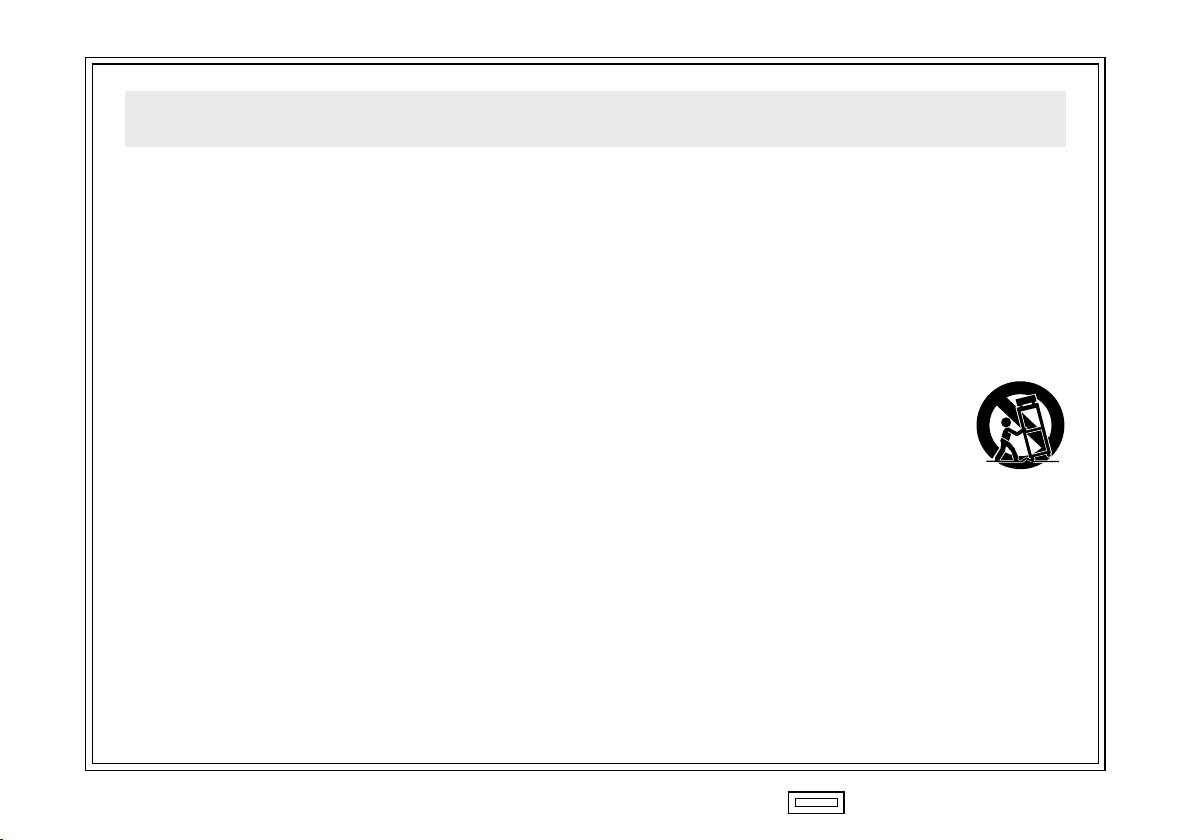
12) Use only with the cart, stand, tripod,
bracket, or tabl e s pecified by
the manufacturer, or sold with the
apparatus. When a cart is used, use
c a ut io n w he n m o vi n g t h e
cart/apparatus combination to avoid
injury from tip-over.
13) Unplug this apparatus during lightning storms or
when unused for long periods of time.
14) Refer all servicing to qualified service personnel.
Servicing is required when the apparatus has
been damaged in any way, such as power-supply
cord or plug is damaged, liquid has been spilled or
objects have fallen into the apparatus, the
apparatus has been exposed to rain or moisture,
does not operate normally, or has been dropped.
Read these operating instructions carefully before using the unit. Follow the safety instructions on the unit and the
applicable safety instructions listed below. Keep these operating instructions handy for future reference.
IMPORTANT SAFETY INSTRUCTIONS
Page 5

- 4 (E) -
ENGLISH
• Power Off Before Connecting or Disconnecting Cables.
Before plugging or unplugging the cables, be sure to switch
power off.
• Handle Carefully.
Do not drop the product, or subject it to strong shock or
vibration. This is important to prevent trouble.
• Avoid Humidity and Dust.
Avoid using the product at a humid, dusty place because
much humidity and dust will cause damage to the parts
inside.
• Operating Temperature Range
Avoid using the product at a cold place below 14°F (–10°C)
or at a hot place above 113°F (+45°C) because extremely
low or high temperature will adversely affect the parts
inside.
Precautions for use
Contents
Precautions for use .......................................................... 4
Introduction ....................................................................... 5
Major operating controls and their functions ................ 6
Connections ...................................................................... 9
Wh en controlling AW-PH400 from AW-RP605A
(AW-RP605/AW-RP555/AW-RP655) .................. 10
Wh en using the extended distance
transmission function of AW-RP400
and AW-PH400 (AW-PH360) .............................. 11
Wh en controlling AW-PH350 (AW-PH360/AW-PH650)
from AW-RP400 .................................................. 12
Appearance ..................................................................... 13
Specifications ................................................................. 14
Page 6

- 5 (E) -
Introduction
By using this unit, AW-PH400 can be controlled from AW-RP605/AW-RP605A/AW-RP655/AW-RP555.
Additionally, the controllable distance between AW-RP400 and AW-PH400/AW-PH360 can be extended up to
3,280 feet (1,000 meters).
AW-PH350/AW-PH360/AW-PH650 can also be controlled from AW-RP400.
Notes
The connections other than above examples cannot be done.
When controlling the AW-PH400 from the AW-RP605A:
• The AW-PH400 has no backlash so it is not necessary to adjust the backlash compensation.
• The maximum memory time of the tracing memory is 300 seconds.
• DIAGONAL MOTION cannot be set from ON to OFF or vice versa. It is always in effect.
• PRESET SPEED can be changed by setting DIAGONAL MOTION to ON and adjusting the DIAGONAL SPEED value.
• The maximum controllable distance is 1,000 meters between the AW-RP605A and AW-IF400G and 500 meters between the
AW-PH400 and AW-IF400G.
When controlling the AW-PH350 from the AW-RP400:
• The tracing memory data cannot be stored, played or deleted.
• TILT RANGE cannot be switched. It is fixed at 190 degrees.
• Backlash in the AW-PH350 cannot be compensated for.
• DIAGONAL MOTION cannot be set.
• The maximum controllable distance is 500 meters between the AW-RP400 and AW-IF400G and 1,000 meters between the
AW-PH350 and AW-IF400G.
Page 7
- 6 (E) -
ENGLISH
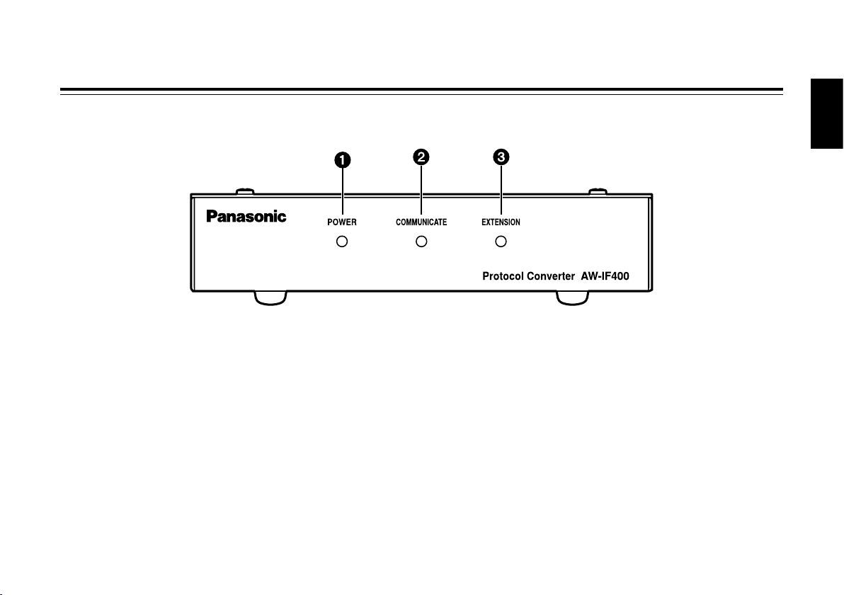
Major operating controls and their functions
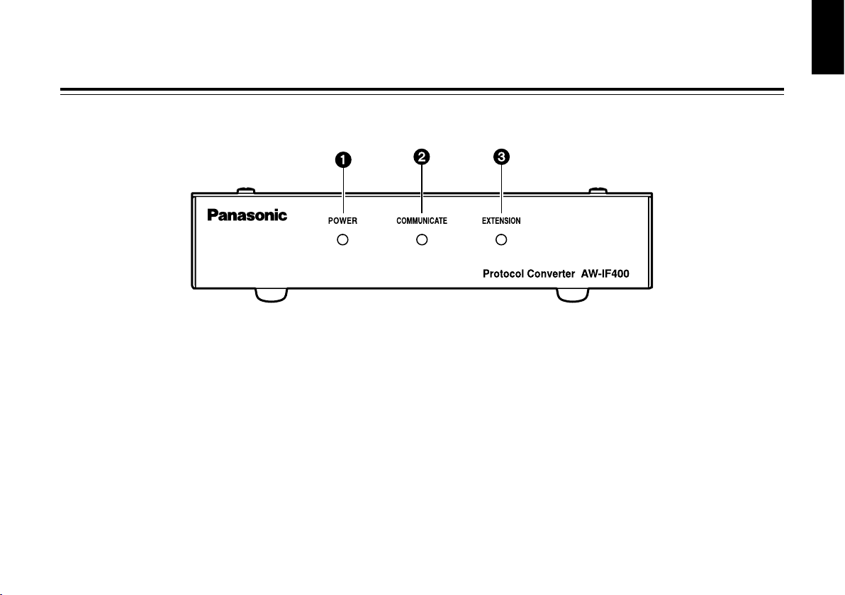
Power LED [POWER]
This lights up green when DC power is supplied to the DC
12 V input connector .
Transmission Status LED [COMMUNICATE]
This lights up when data is being transmitted between the
controller and pan/tilt head.
Extended Distance Transmission LED [EXTENSION]
This lights up when this unit is used to extend the
transmission distance between AW-RP400 and
AW-PH400.
Front panel
Page 8

- 7 (E) -
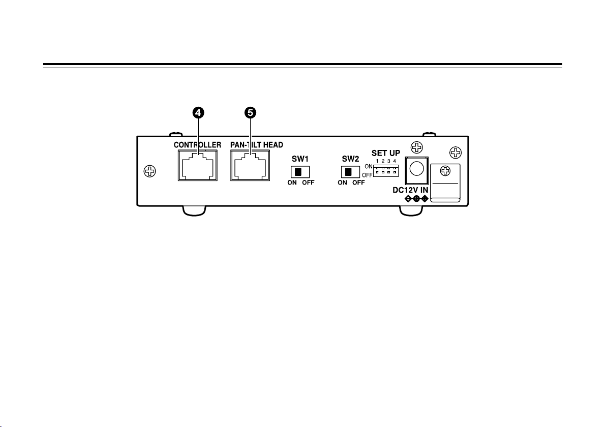
Major operating controls and their functions
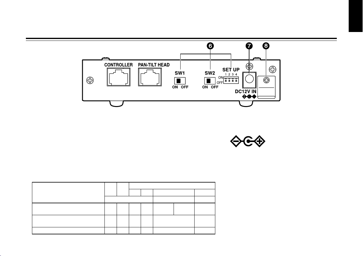
Rear panel
Controller connector [CONTROLLER]
Use the controller CONTROL OUT TO PAN/TILT terminal
and a 10BASE-T (equivalent to UTP category 5) straight
cable for connection.
Pan/tilt head connector [PAN-TILT HEAD]
Use the pan/tilt head IP/RP terminal and a 10BASE-T
(equivalent to UTP category 5) straight cable for
connection.
Page 9
- 8 (E) -
ENGLISH
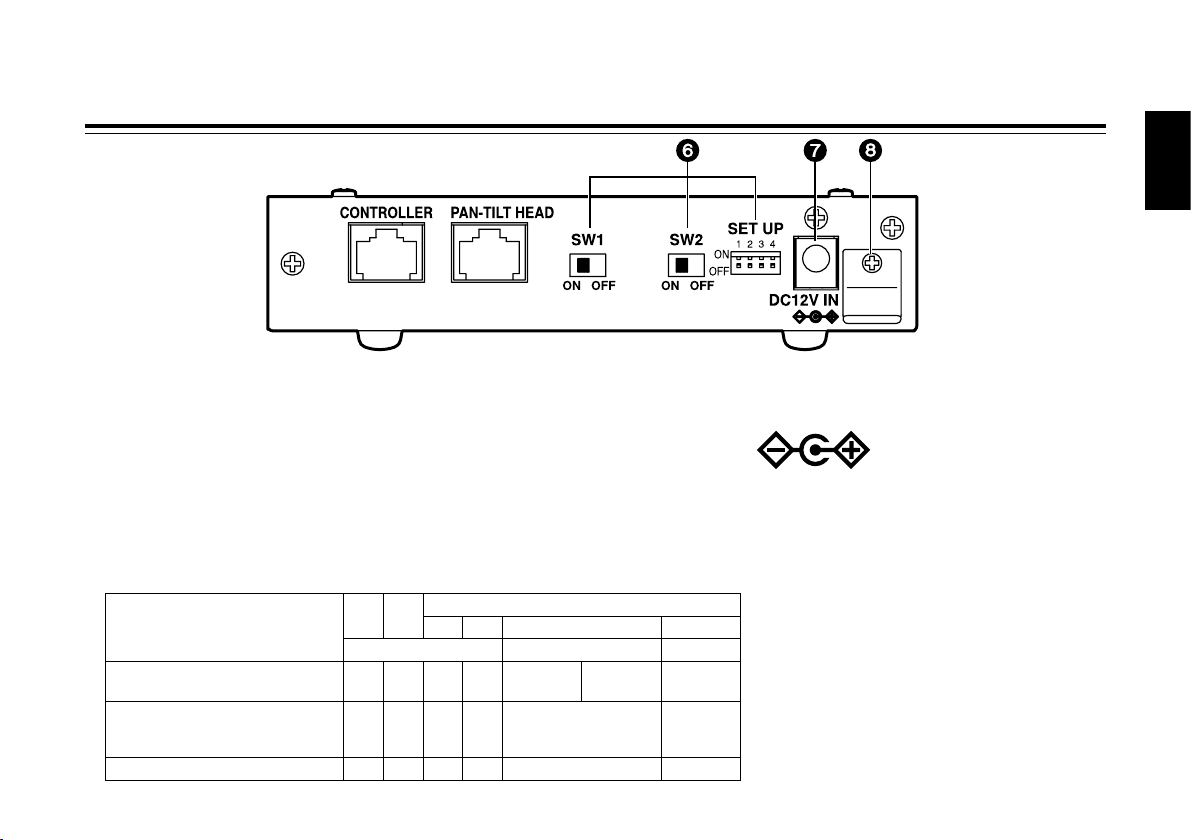
Major operating controls and their functions
Function Switches [SW1, SW2, SET UP]
(Factory defaults: SW1 = OFF, SW2 = OFF,
SET UP No.1 = ON, SET UP No.2 to 4 = OFF)
This is used to select the operations of the AW-IF400.
Before changing a setting, the power must be turned off.
SETUP No.3 is the tilt range selector switch which is used
to control the AW-PH400 from the AW-RP605A.
At the ON position, the range is 300 degrees; at the OFF
position, it is 190 degrees. For any other combination, use
the switch at the OFF position.
Functions
SW1 SW2
SET UP
No.1 No.2 No.3 No.4
MODE SET TILT RANGE NOT USE
Controlling PH400 from RP605A OFF OFF ON OFF
ON
(300 deg)
OFF
(190 deg)
OFF
Extending communication distance
between RP400 and PH400
ON ON OFF OFF
OFF
(Set at RP400)
OFF
Controlling PH350 from RP400 OFF ON OFF ON OFF OFF
DC 12 V input connector [DC12V IN]
Connect the AW-PS505A AC adapter (sold separately) to
this socket.
Cable clamp
This is used to clamp the power cable in place and
prevent it from coming loose.
Page 10

- 9 (E) -
Connections
• Before proceeding with the connections, turn off the power.
• For further details on connecting the devices, refer to the operating instructions accompanying
the devices concerned.
• For further details on operating the devices, refer to the operating instructions accompanying
the devices concerned.
• Use a separate cable compensator if the video signal cable is longer than 500 meters.
Page 11
- 10 (E) -
ENGLISH
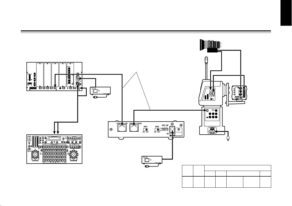
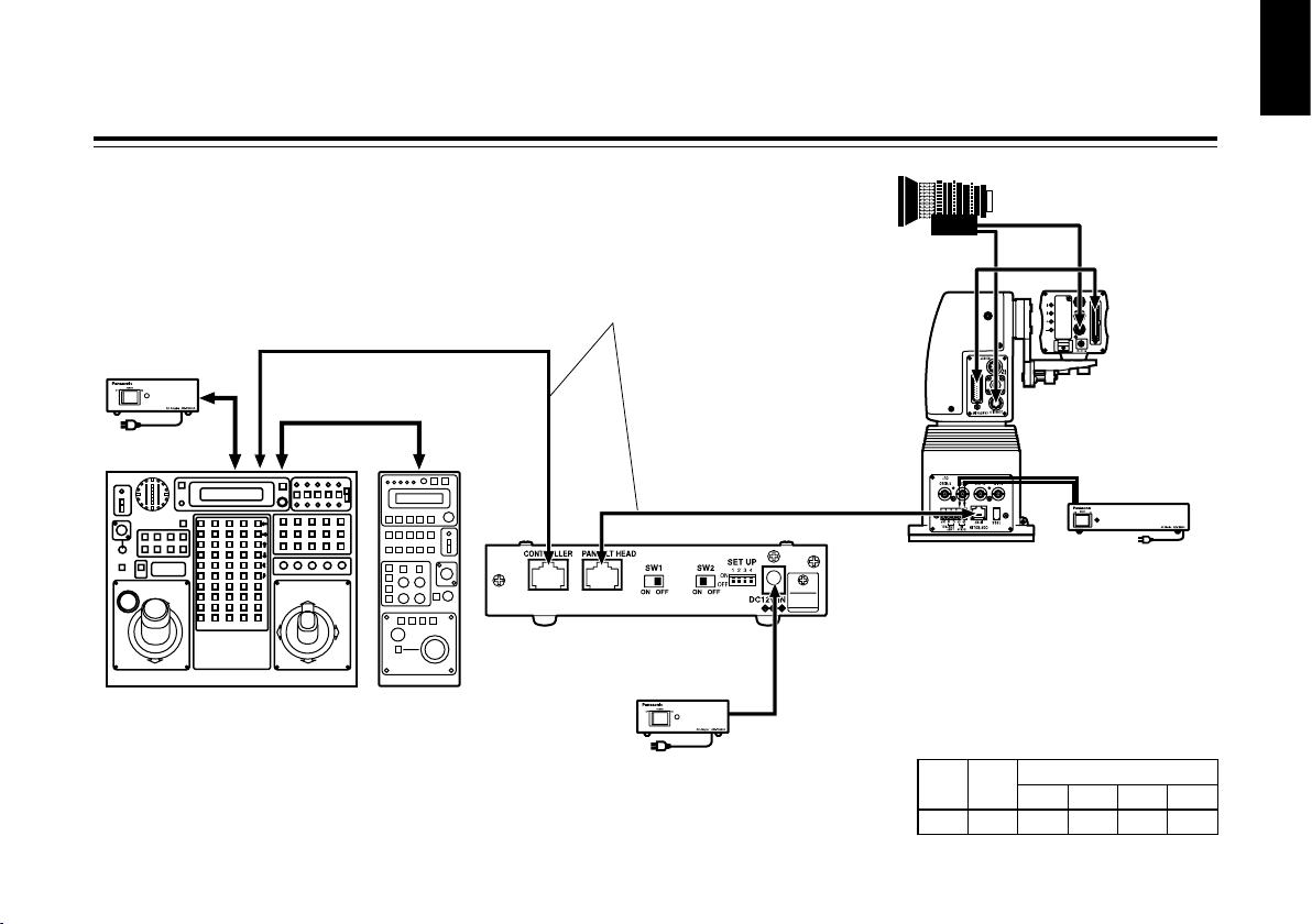
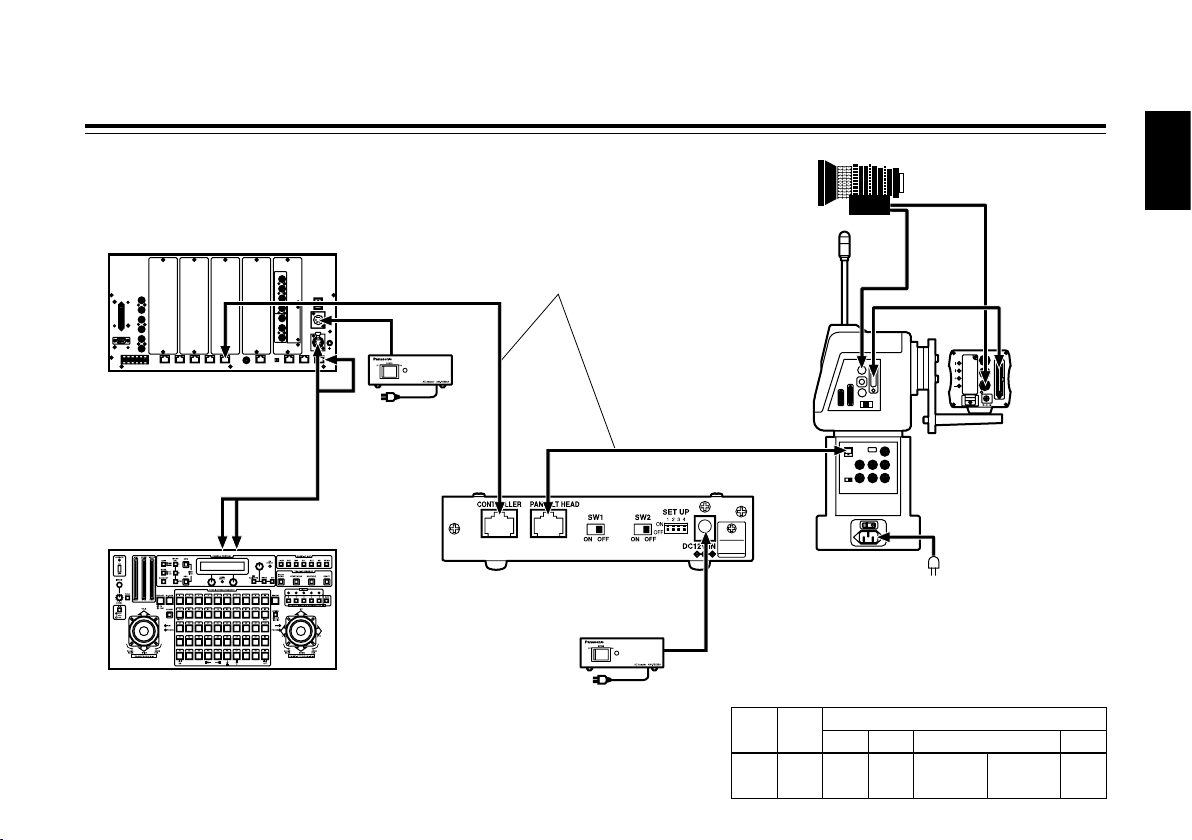
Connections
CONTROL OUT
TO PAN/TILT HEAD
Main unit
Control panel
(max. 1000 m)
(max. 500 m)
Multi-function controller
AW-RP605A
10BASE-T (UTP category 5)
straight cable
AC adapter
AW-PS505A
Convertible
camera
Camera cable
supplied with
AW-PH400
AC power cable
supplied with
AW-PH400
Protocol converter
AW-IF400G
AC adapter
AW-PS505A
Zoom lens
IP/RP
Indoor pan/tilt head
AW-PH400
When controlling AW-PH400
from AW-RP605A (AW-RP605/AW-RP555/AW-RP655)
• Switch settings
SW1 SW2
SET UP
1 2 3 4
OFF OFF ON OFF
ON
(300 deg)
OFF
(190 deg)
OFF
Page 12
- 11 (E) -
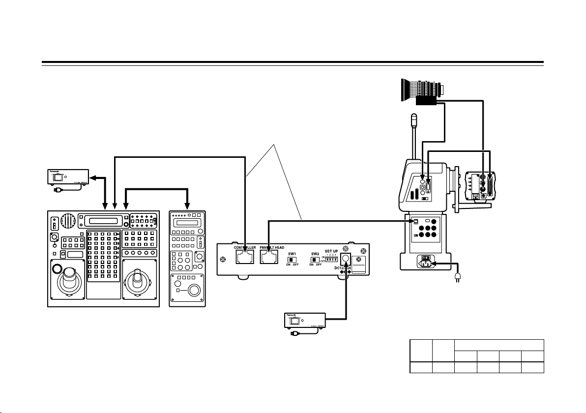
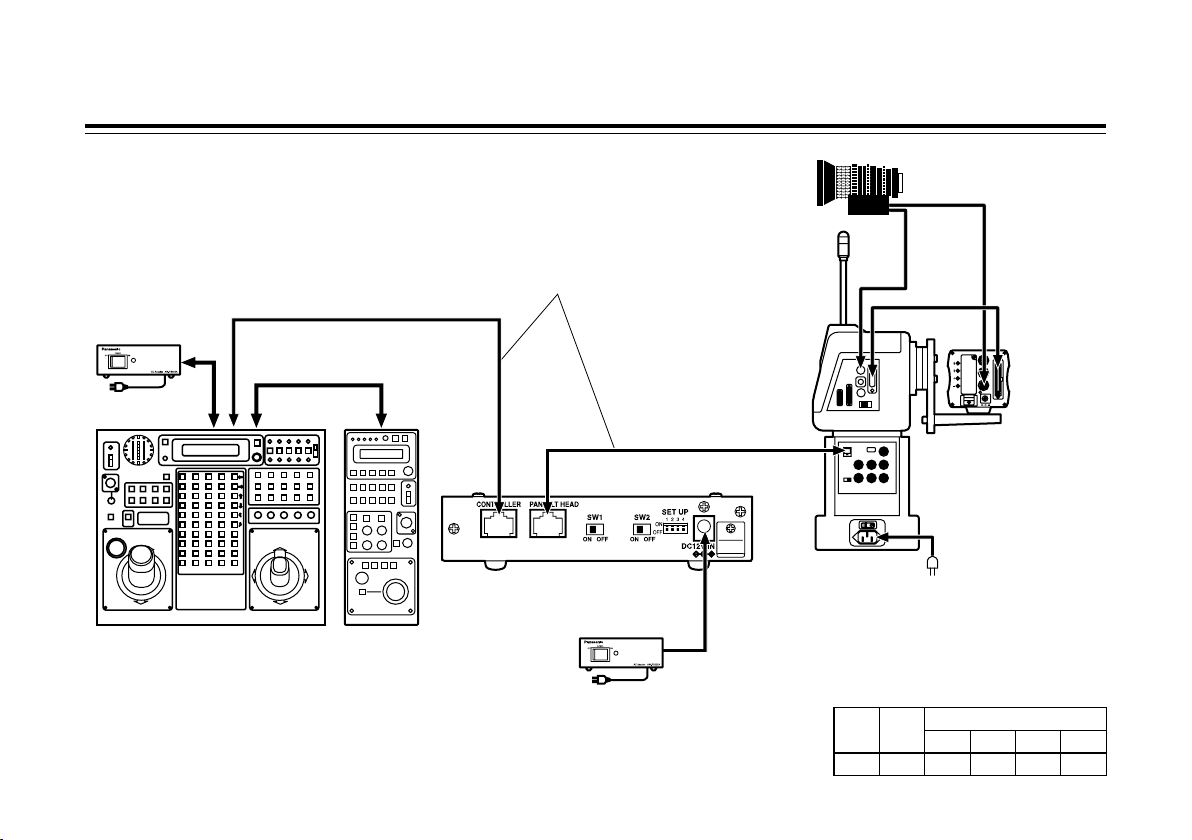
Connections
Pan/tilt control panel
AW-RP400
Remote
operation
panel
AW-CB400
CONTROL OUT
TO PAN/TILT
HEAD
10BASE-T (UTP category 5)
straight cable
Protocol converter
AW-IF400G
IP/RP
Indoor pan/tilt head
AW-PH400
When using the extended distance transmission function
of AW-RP400 and AW-PH400 (AW-PH360)
AC adapter
AW-PS505A
Convertible
camera
Camera cable
supplied with
AW-PH400
AC power cable
supplied with
AW-PH400
Zoom lens
AC adapter
AW-PS505A
(max. 500 m)
(max. 500 m)
• Switch settings
SW1 SW2
SET UP
1 2 3 4
ON ON OFF OFF OFF OFF
Page 13
- 12 (E) -
ENGLISH
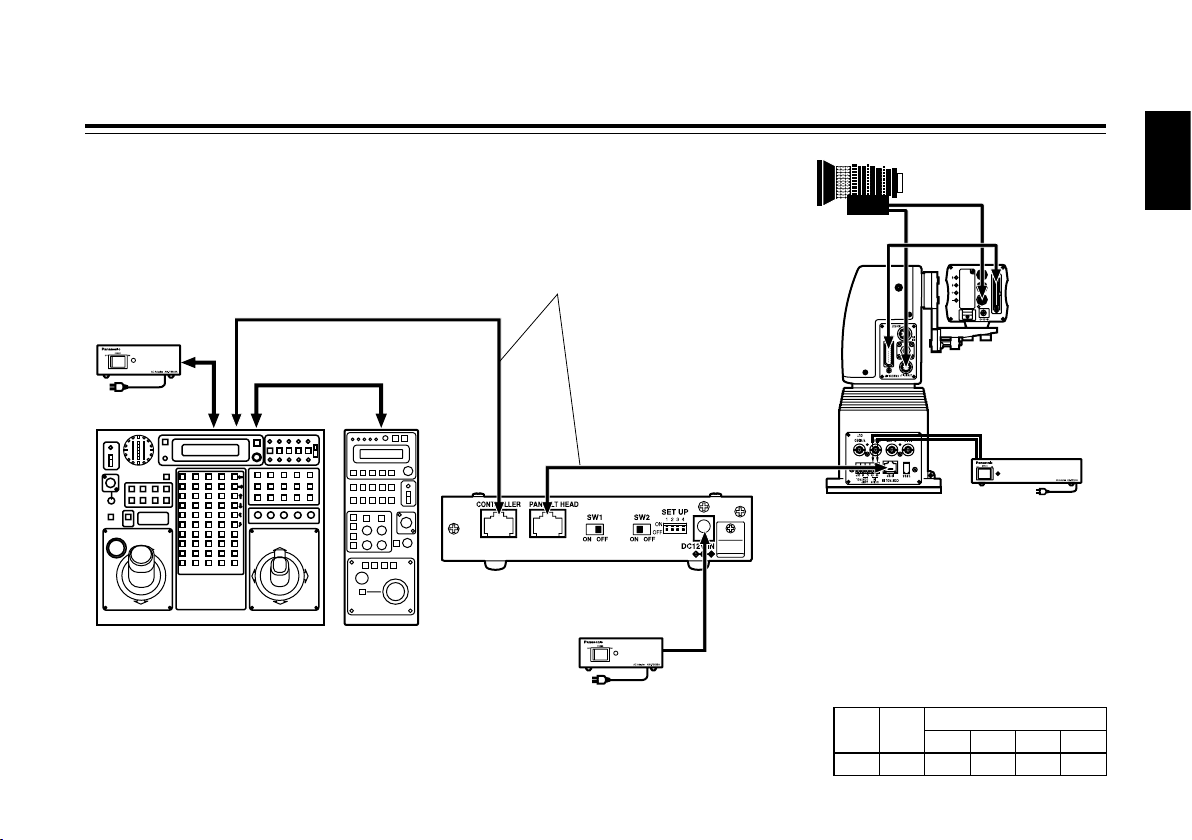
Connections
When controlling AW-PH350 (AW-PH360/AW-PH650)
from AW-RP400
CONTROL IN
IP/RP
Indoor pan/tilt head
AW-PH350
Pan/tilt control panel
AW-RP400
CONTROL OUT
TO PAN/TILT
HEAD
10BASE-T (UTP category 5)
straight cable
Protocol converter
AW-IF400G
Remote
operation
panel
AW-CB400
AC adapter
AW-PS505A
Convertible
camera
Camera cable
AW-CA50T29
AW-CA50C29
AC adapter
AW-PS300A
Zoom lens
AC adapter
AW-PS505A
(max. 500 m)
(max. 1000 m)
• Switch settings
SW1 SW2
SET UP
1 2 3 4
OFF ON OFF ON OFF OFF
Page 14
- 13 (E) -
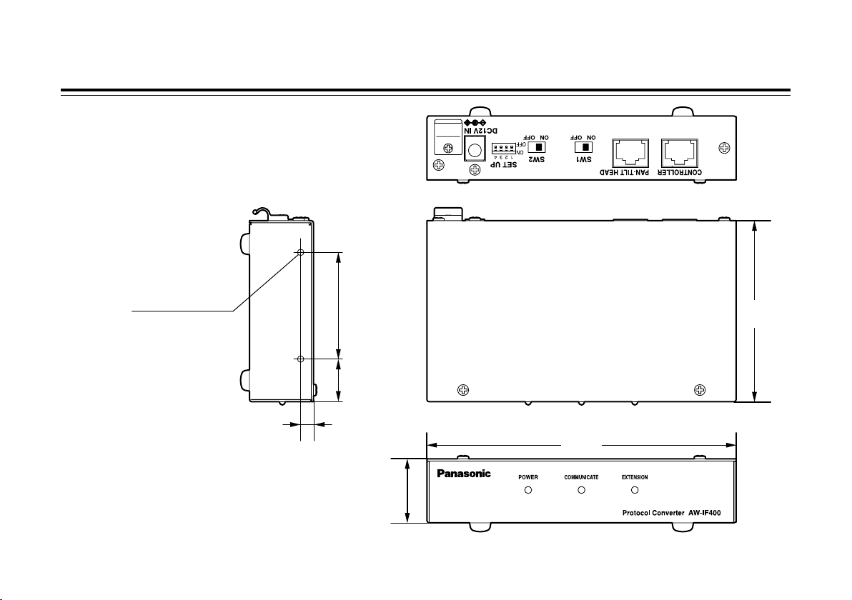
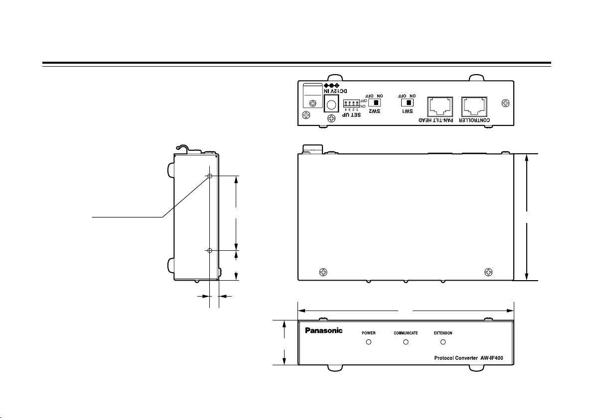
1/4
(6)
1-15/16
(50)
13/16
(20)
5-11/16
(145)
3-3/8
(85)
1-3/16
(30)
Appearance
For mounting and other applications, use the screw
(M3 screw) holes in the side panels.
Do not use screws longer than 10 mm.
Unit: inch (mm)
M3 screw hole
(in 4 locations)
( Located in the
same positions
on both sides)
Page 15
- 14 (E) -
ENGLISH
Specifications
Controller supported: AW-RP400, AW-RP555, AW-RP605, AW-RP605A, AW-RP655
Pan/tilt head supported: AW-PH350, AW-PH360, AW-PH400, AW-PH650
Input connectors
DC 12 V IN socket: Supply DC 12 V from the general-purpose AC adapter.
(Recommended AC adapter: AW-PS505A)
Input/Output connector
CONTROLLER: RJ45, modular jack
10BASE-T straight cable (UTP category 5)
PAN-TILT HEAD: RJ45, modular jack
10BASE-T straight cable (UTP category 5)
Switch functions: Controller / Pan/Tilt Head selector switch (SW1, SW2, SET UP)
Indicator: POWER, COMMUNICATE, EXTENSION
Allowable operating temperature:
14°F to 113°F (–10°C to +45°C)
Ambient operating humidity: 30% to 90% (no condensation)
Dimensions (WHD): 5-11/16”1-3/16”3-3/8” (1453085 mm) (excluding rubber feet)
Weight: Approx. 0.9 lbs. (0.4 kg)
Finish: AV ivory paint (color resembling Munsell 7.9Y 6.8/0.8)
Weight and dimensions indicated are approximate.
Specifications are subject to change without notice.
Source voltage: DC 10.8 V to DC 16.0 V
Power consumption: 1.5 W
indicates safety information.
Page 16
- 1 (G) -
ist die Sicherheitsinformation.
DEUTSCHE AUSGABE
(GERMAN VERSION)
Öff nen Si e n i cht da s Ge rät du r ch
Abschrauben von Gehäuseteilen.
Zur Vermeidung von elektrischem Schlag darf das
Gehäuse nicht geöffnet werden. Im Geräteinneren
befinden sich keine Teile, die vom Benutzer gewartet
werden können.
Wartungs- und Reparaturarbeiten grundsätzlich
autorisiertem Kundendienstpersonal überlassen.
WARNUNG:
• ZUR REDUZIERUNG DER GEFAHR VON BRAND
UND ELE K T RISC H E M S C HLAG D I ESES
GERÄT WEDER NÄSSE NOCH FEUCHTIGKEIT
AUSSETZEN.
• UM BRAND- ODER STROMSCHLAGGEFAHR ZU
REDUZIEREN , MUSS DIESES GERÄT VO N
ALLE N FLÜSSIG K EITEN FER N GEHALTEN
WERDEN. VERMEIDEN SIE GEBRAUCH UND
LAGERUNG DES GERÄTES AN ORTEN, AN
DENEN DIE GEFAHR BESTEHT, DASS ES MIT
FLÜSSIGKEITEN BETROPFT ODER BESPRITZT
W IR D, U N D S T E L LE N S I E K E I N E
FLÜSSIGKEITSBEHÄLTER AUF DAS GERÄT.
VORSICHT:
NUR DAS EMPFOHLENE ZUBEHÖR VERWENDEN,
U M D I E G E F A HR V O N F E U ER U ND
ELEKTRISCHEM SCHLAG SOWIE STÖRUNGEN
AUSZUSCHALTEN.
Hinweis:
Das Typenschild (Seriennummerschild) befindet
sich an der Unterseite des Gerätes.
Page 17
- 2 (G) -
DEUTSCH
Benutzerinformationen zur Entsorgung von elektrischen und elektronischen Geräten (private Haushalte)
Dieses Symbol auf Produkten und/oder begleitenden Dokumenten bedeutet, dass verbrauchte elektrische und
elektronische Produkte nicht mit gewöhnlichem Haushaltsabfall vermischt werden sollen.
Bringen Sie zur ordnungsgemäßen Behandlung, Rückgewinnung und Recycling diese Produkte zu den
entsprechenden Sammelstellen, wo sie ohne Gebühren entgegengenommen werden. In einigen Ländern kann
es auch möglich sein, diese Produkte beim Kauf eines entsprechenden neuen Produkts bei Ihrem örtlichen
Einzelhändler abzugeben.
Die ordnungsgemäße Entsorgung dieses Produkts dient dem Umweltschutz und verhindert mögliche schädliche
Auswirkungen auf Mensch und Umgebung, die aus einer unsachgemäßen Handhabung von Abfall entstehen können.
Genauere Informationen zur nächstgelegenen Sammelstelle erhalten Sie bei Ihrer Gemeindeverwaltung.
In Übereinstimmung mit der Landesgesetzgebung können für die unsachgemäße Entsorgung dieser Art von Abfall
Strafgebühren erhoben werden.
Für Geschäftskunden in der Europäischen Union
Bitte treten Sie mit Ihrem Händler oder Lieferanten in Kontakt, wenn Sie elektrische und elektronische Geräte entsorgen
möchten. Er hält weitere Informationen für sie bereit.
Informationen zur Entsorgung in anderen Ländern außerhalb der Europäischen Union
Dieses Symbol ist nur in der Europäischen Union gültig.
Bitte treten Sie mit Ihrer Gemeindeverwaltung oder Ihrem Händler in Kontakt, wenn Sie dieses Produkt entsorgen möchten,
und fragen Sie nach einer Entsorgungsmöglichkeit.
Page 18

- 3 (G) -
Inhalt
Vorsichtsmaßnahmen zum Gebrauch ................................................................................................................. 4
Einleitung ............................... 5
Wichtige Bedienungselemente und ihre Funktionen ......................................................................................... 6
Anschlüsse ............................ 9
Bei Steuerung von AW-PH400 über AW-RP605A (AW-RP605/AW-RP555/AW-RP655) .............................. 10
Bei Verwendung der Übertragungsentfernungsverlängerungsfunktion
von AW-RP400 und AW-PH400 (AW-PH360) ......................................................................................... 11
Bei Steuerung von AW-PH350 (AW-PH360/AW-PH650) über AW-RP400 ................................................... 12
Aussehen ............................. 13
Technische Daten ................ 14
Page 19

- 4 (G) -
DEUTSCH
• Stromversorgung ausschalten, bevor Kabel
angeschlossen oder abgetrennt werden.
Vor dem Anstecken oder Abziehen der Kabel, unbedingt
die Stromversorgung ausschalten.
• Vorsichtig handhaben.
Das Produkt nicht fallen lassen oder starken Stößen bzw.
Erschütterungen aussetzen. Anderenfalls kann es zu
Störungen kommen.
• Feuchtigkeit und Staub vermeiden.
Vermeiden Sie die Verwendung dieses Produkts an einem
feuchten oder staubigen Ort, da übermäßige Feuchtigkeit
oder Staub zu einer Beschädigung der internen Teile
führen kann.
• Den zulässigen Temperaturbereich einhalten.
Vermeiden Sie eine Verwendung dieses Produkts an
einem sehr kalten (unter –10°C) oder sehr warmen (über
+45°C) Ort, da extrem niedrige oder hohe Temperaturen
die internen Teile negativ beeinflussen.
Vorsichtsmaßnahmen zum Gebrauch
Page 20

- 5 (G) -
Einleitung
Der Einsatz dieses Gerätes ermöglicht die Steuerung des Modells AW-PH400 über die Steuergeräte AW-RP605/AW-RP605A/
AW-RP655/AW-RP555.
Darüber hinaus kann die Steuersignalverbindung zwischen AW-RP400 und AW-PH400/AW-PH360 bis auf 1.000 m verlängert
werden.
Die Modelle AW-PH350/AW-PH360/AW-PH650 können auch über AW-RP400 gesteuert werden.
Hinweise
Anschlüsse außer den obigen Beispielen sind nicht durchführbar.
Bei Steuerung des AW-PH400 über das AW-RP605A:
• Da der AW-PH400 keinen Totgang aufweist, erübrigt sich die Durchführung des Spielausgleichs.
• Die maximale Speicherzeit des Ablaufspeichers beträgt 300 Sekunden.
• DIAGONAL MOTION kann nicht von ON auf OFF oder umgekehrt gesetzt werden. Die Funktion ist immer wirksam.
• PRESET SPEED kann geändert werden, indem DIAGONAL MOTION auf ON gesetzt und der Wert für DIAGONAL SPEED
eingestellt wird.
• Die maximale Steuersignal-Übertragungsentfernung beträgt 1.000 m zwischen AW-RP605A und AW-IF400G und 500 m
zwischen AW-PH400 und AW-IF400G.
Bei Steuerung des AW-PH350 über das AW-RP400:
• Die Ablaufspeicherdaten können nicht gespeichert, wiedergegeben oder gelöscht werden.
• TILT RANGE kann nicht umgeschaltet werden. Der Wert ist auf 190 Grad fixiert.
• Der Totgang im AW-PH350 kann nicht ausgeglichen werden.
• DIAGONAL MOTION kann nicht eingestellt werden.
• Die maximale Steuersignal-Übertragungsentfernung beträgt 500 m zwischen AW-RP400 und AW-IF400G und 1.000 m
zwischen AW-PH350 und AW-IF400G.
Page 21
- 6 (G) -
DEUTSCH
Wichtige Bedienungselemente und ihre Funktionen
Betriebs-LED [POWER]
Diese LED leuchtet grün auf, wenn Gleichstrom der
12-V-Gleichstrom-Eingangsbuchse () zugeführt wird.
Übertragungsstatus-LED [COMMUNICATE]
Diese LED leuchtet auf, wenn Daten zwischen
Steuergerät und Schwenk-/Neigekopf übertragen werden.
Übertragungsentfernungsverlängerungs-LED
[EXTENSION]
Diese LED leuchtet auf, wenn dieses Gerät zur
Verlängerung der Übertragungsentfernung zwischen
AW-RP400 und AW-PH400 verwendet wird.
Fronttafel
Page 22
- 7 (G) -
Wichtige Bedienungselemente und ihre Funktionen
Rückseite
Steuergerätebuchse [CONTROLLER]
Verbinden Sie diese Buchse über ein 10BASE-TGeradkabel (entspricht UTP-Kategorie 5) mit der Buchse
CONTROL OUT TO PAN/TILT des Steuergerätes.
Schwenk-/Neigekopfbuchse [PAN-TILT HEAD]
Verbinden Sie diese Buchse über ein 10BASE-TGeradkabel (entspricht UTP-Kategorie 5) mit der Buchse
IP/RP des Schwenk-/Neigekopfes.
Page 23
- 8 (G) -
DEUTSCH
Wichtige Bedienungselemente und ihre Funktionen
Funktionsschalter [SW1, SW2, SET UP]
(Werksvorgaben: SW1 = OFF, SW2 = OFF,
SET UP Nr. 1 = ON, SET UP Nr. 2 bis 4 = OFF)
Dieser Schalter dient zur Wahl der Operationen des
AW-IF400. Bevor eine Einstellung geändert wird, muss
das Gerät ausgeschaltet werden. SETUP Nr. 3 ist der
Neigungsbereich-Wahlschalter, der zur Steuerung des
AW-PH400 über AW-RP605A verwendet wird. In der
Position ON beträgt der Bereich 300 Grad, in der Position
OFF sind es 190 Grad. Für jede andere Kombination ist
der Schalter auf die Position OFF zu stellen.
Funktionen
SW1 SW2
SET UP
Nr.1 Nr.2 Nr.3 Nr.4
MODE SET TILT RANGE NOT USE
Steuerung von PH400 über RP605A OFF OFF ON OFF
ON
(300 Grad)
OFF
(190 Grad)
OFF
Verlängerung der
Kommunikationsentfernung
zwischen RP400 und PH400
ON ON OFF OFF
OFF
(Auf RP400 stellen)
OFF
Steuerung von PH350 über RP400 OFF ON OFF ON OFF OFF
12-V-Gleichstrom-Eingangsbuchse [DC12V IN]
Schließen Sie das Netzgerät AW-PS505A (getrennt
erhältlich) an diesen Eingang an.
Kabelklemme
Diese Klemme dient zur Sicherung des Netzkabels, damit
es sich nicht löst.
Page 24

- 9 (G) -
Anschlüsse
• Schalten Sie die Stromversorgung aus, bevor Sie mit den Anschlüssen beginnen.
• Weitere Einzelheiten über den Anschluss der Geräte entnehmen Sie bitte den
Gebrauchsanleitungen der betreffenden Geräte.
• Weitere Einzelheiten über den Betrieb der Geräte entnehmen Sie bitte den
Gebrauchsanleitungen der betreffenden Geräte.
• Verwenden Sie einen getrennten Kabelkompensator, falls das Videosignalkabel länger
als 500 m ist.
Page 25
- 10 (G) -
DEUTSCH
Anschlüsse
Bei Steuerung von AW-PH400 über
AW-RP605A (AW-RP605/AW-RP555/AW-RP655)
CONTROL OUT
TO PAN/TILT HEAD
Hauptgerät
Steuerpult
Multifunktions-Steuergerät
AW-RP605A
10BASE-T-Geradkabel
(entsprechend UTP-Kategorie 5)
Protokollkonverter
AW-IF400G
IP/RP
Innenraum-Schwenk-
/Neigekopf
AW-PH400
Netzgerät
AW-PS505A
Konvertierbare
Kamera
Mit AW-PH400
geliefertes
Kamerakabel
Mit AW-PH400
geliefertes
Netzkabel
Zoomobjektiv
Netzgerät
AW-PS505A
(max. 1000 m)
(max. 500 m)
• Schalterstellungen
SW1 SW2
SET UP
1 2 3 4
OFF OFF ON OFF
ON
(300 Grad)
OFF
(190 Grad)
OFF
Page 26
- 11 (G) -
Anschlüsse
Bei Verwendung der Übertragungsentfernungsverlängerungsfunktion
von AW-RP400 und AW-PH400 (AW-PH360)
Schwenk-/Neigesteuerpult
AW-RP400
CONTROL OUT
TO PAN/TILT
HEAD
10BASE-T-Geradkabel
(entsprechend UTP-Kategorie 5)
Protokollkonverter
AW-IF400G
IP/RP
Innenraum-Schwenk-
/Neigekopf
AW-PH400
Fernsteuerkonsole
AW-CB400
Netzgerät
AW-PS505A
Konvertierbare
Kamera
Mit AW-PH400
geliefertes
Kamerakabel
Mit AW-PH400
geliefertes
Netzkabel
Zoomobjektiv
Netzgerät
AW-PS505A
(max. 500 m)
(max. 500 m)
• Schalterstellungen
SW1 SW2
SET UP
1 2 3 4
ON ON OFF OFF OFF OFF
Page 27
- 12 (G) -
DEUTSCH
Anschlüsse
Bei Steuerung von AW-PH350 (AW-PH360/AW-PH650)
über AW-RP400
CONTROL IN
IP/RP
Innenraum-Schwenk-
/Neigekopf
AW-PH350
Schwenk-/Neigesteuerpult
AW-RP400
CONTROL OUT
TO PAN/TILT
HEAD
10BASE-T-Geradkabel
(entsprechend UTP-Kategorie 5)
Protokollkonverter
AW-IF400G
Fernsteuerkonsole
AW-CB400
Netzgerät
AW-PS505A
Konvertierbare
Kamera
Kamerakabel
AW-CA50T29
AW-CA50C29
Netzgerät
AW-PS300A
Zoomobjektiv
Netzgerät
AW-PS505A
(max. 500 m)
(max. 1000 m)
• Schalterstellungen
SW1 SW2
SET UP
1 2 3 4
OFF ON OFF ON OFF OFF
Page 28
- 13 (G) -
145
85
30
6
50
20
Aussehen
Verwenden Sie die Gewindebohrungen (M3-Gewinde)
in den Seitenplatten für Befestigung und andere
Anwendungen.
Verwenden Sie keine Schrauben von mehr als 10 mm
Länge.
Einheit: mm
M3-Gewindebohrung
(an 4 Stellen)
( Identische
Positionen auf
beiden Seiten)
Page 29
- 14 (G) -
DEUTSCH
Technische Daten
Unterstütztes Steuergerät: AW-RP400, AW-RP555, AW-RP605, AW-RP605A, AW-RP655
Unterstützte Schwenk-/Kippköpfe: AW-PH350, AW-PH360, AW-PH400, AW-PH650
Eingänge
Buchse DC 12 V IN: Versorgung mit 12 V Gleichstrom von Allzweck-Netzgerät.
(Empfohlenes Netzgerät: AW-PS505A)
Eingänge/Ausgänge
CONTROLLER: RJ45, Modulbuchse
10BASE-T-Geradkabel (UTP-Kategorie 5)
PAN-TILT HEAD: RJ45, Modulbuchse
10BASE-T-Geradkabel (UTP-Kategorie 5)
Schalterfunktionen: Steuergerät / Schwenk-/Neigekopf-Wahlschalter (SW1, SW2, SET UP)
Anzeigelampen: POWER, COMMUNICATE, EXTENSION
Betriebstemperatur: –10°C bis +45°C
Betriebsluftfeuchtigkeit: 30% bis 90% (keine Kondensation)
Abmessungen (BHT): 1453085 mm (ohne Gummifüße)
Gewicht: ca. 0,4 kg
Gehäuse: AV-Elfenbeinlack (Farbe entspricht Munsell 7.9Y6.8/0.8)
Bei den obigen Gewichts- und Abmessungsangaben handelt es sich um Näherungswerte.
Änderungen der technischen Daten vorbehalten.
Versorgungsspannung: 10,8 bis 16,0 V Gleichstrom
Leistungsaufnahme: 1,5 W
ist die Sicherheitsinformation.
Page 30
- 1 (F) -
Informations concernant la sécurité.
VERSION FRANÇAISE
(FRENCH VERSION)
Ne pas dévisser le couvercle.
Pour réduire tout risque d’électrocution, ne pas retirer
le couvercle. Il ne se trouve à l’intérieur aucune pièce
qui puisse être réparée par l’utilisateur.
Confier toute réparation à un personnel qualifié.
AVERTISSEMENT:
• POUR RÉDUIRE LES RISQUES D’INCENDIE OU
DE CHOC ÉLECTRIQUE, ÉVITEZ D’EXPOSER
CET APPAREIL À LA PLUIE OU À L’HUMIDITÉ.
• POUR RÉDUIRE TOUT RISQUE DE FEU OU DE
CHOC ÉLECTRIQUE, ÉLOIGNER L’APPAREIL
DES LIQUIDES - U TILISER ET R A N G ER
UNIQUEMENT DANS UN ENDROITNE RISQUANT
PAS DE RECEVOIR DES GOUTTES OU D’ÊTRE
ASPERGÉ DE LIQUIDES, ET NE PAS METTRE DE
RÉCIPIENT RENFERMANT DES LIQUIDES SUR
LE DESSUS DE L’APPAREIL.
ATTENTION:
POUR ÉVITER TOUT RISQUE D’INCENDIE, DE
CHOCS ÉLECTRIQUES OU D’INTERFÉRENCES,
N ’ UT I LI S ER Q UE LE S A C C ES S OI R ES
RECOMMANDÉS.
Remarque:
La plaque signalétique (plaque du numéro de
série) est située sur la face inférieure de
l’appareil.
Page 31

- 2 (F) -
FRANÇAIS
Informations relatives à l’évacuation des déchets, destinées aux utilisateurs d’appareils électriques et
électroniques (appareils ménagers domestiques)
Lorsque ce symbole figure sur les produits et/ou les documents qui les accompagnent, cela signifie que les
appareils électriques et électroniques ne doivent pas être jetés avec les ordures ménagères.
Pour que ces produits subissent un traitement, une récupération et un recyclage appropriés, envoyez-les dans
les points de pré-collecte désignés, où ils peuvent être déposés gratuitement. Dans certains pays, il est
possible de renvoyer les produits au revendeur local en cas d’achat d’un produit équivalent.
En éliminant correctement ce produit, vous contriburez à la conservation des ressources vitales et à la
prévention des éventuels effets négatifs sur l’environnement et la santé humaine, pouvant être dus à la manipulation
inappropriée des déchets.
Veuillez contacter les autorités locales pour connaître le point de pré-collecte le plus proche.
Des sanctions peuvent être appliquées en cas d’élimination incorrecte de ces déchets, conformément à la législation
nationale.
Utilisateurs professionnels de l’Union européenne
Pour en savoir plus sur l’élimination des appareils électriques et électroniques, contactez votre revendeur ou fournisseur.
Informations sur l’évacuation des déchets dans les pays ne faisant pas partie de l’Union européenne
Ce symbole n’est reconnu que dans l’Union européenne.
Pour supprimer ce produit, contactez les autorités locales ou votre revendeur afin de connaître la procédure d’élimination à
suivre.
Page 32

- 3 (F) -
Table des matières
Précautions d’utilisation ....... 4
Introduction ............................ 5
Principaux organes de commande et leurs fonctions ........................................................................................ 6
Raccordements ...................... 9
Quand l’AW-PH400 est pilotée depuis l’AW-RP605A (AW-RP605/AW-RP555/AW-RP655) ......................... 10
Quand la fonction d’augmentation de la distance de transmission entre AW-RP400
et AW-PH400 (AW-PH360) est utilisée ............................................................................................. 11
Quand l’AW-PH350 (AW-PH360/AW-PH650) est pilotée depuis l’AW-RP400 .............................................. 12
Aspect extérieur .................. 13
Fiche technique ................... 14
Page 33

- 4 (F) -
FRANÇAIS
• Couper l’alimentation avant de faire de brancher ou de
débrancher les câbles.
Ne pas oublier de couper l’alimentation avant de brancher
ou de débrancher les câble.
• Manipuler délicatement.
Ne jamais faire tomber l’appareil ni lui subir des chocs
violents ou le soumettre à des vibrations. Pour éviter les
risques de panne, cette précaution est importante.
• Éviter l’humidité et la poussière.
Éviter de mettre l’appareil en service dans un local humide
ou poussiéreux parce que l’humidité et la poussière
finissent par endommager les organes internes.
• Limites de température appareil en service
Éviter la mise en service de l’appareil dans un local à
basse température et notamment inférieure à –10°C ou
un endroit à haute température, température supérieure
à 45°C, parce que les températures extrêmes, haute
et basse, ont un effet nocif sur les organes internes de
l’appareil.
Précautions d’utilisation
Page 34

- 5 (F) -
Introduction
Cet appareil permet de piloter l’AW-PH400 depuis l’AW-RP605/AW-RP605A/AW-RP655/AW-RP555.
Par ailleurs, la plage de distance entre l’AW-RP400 et l’AW-PH400/AW-PH360 peut être augmentée jusqu’à 1000 mètres.
L’AW-PH350/AW-PH360/AW-PH650 peut également être piloté depuis l’AW-RP400.
Remarques
Aucune connexion autre que celles citées ci-dessus n’est possible.
Quand l’AW-PH400 est pilotée depuis l’AW-RP605A:
• Comme l’AW-PH400 n’a pas d’effet de rebond, il n’est pas nécessaire d’ajuster la correction d’effet de rebond.
• Le temps de mémorisation maximum de la mémoire de tracé est de 300 secondes.
• DIAGONAL MOTION ne peut pas être commuté sur ON depuis OFF ou vice versa. Ce réglage est toujours activé.
• Il est possible de modifier PRESET SPEED en commutant DIAGONAL MOTION sur ON et en ajustant la valeur de
DIAGONAL SPEED.
• La plage de commande à distance maximum est de 1000 mètres entre l’AW-RP605A et l’AW-IF400G et 500 mètres entre
l’AW-PH400 et l’AW-IF400G.
Quand l’AW-PH350 est pilotée depuis l’AW-RP400:
• Les données de la mémoire de tracé ne peuvent pas être sauvegardées, lues ou effacées.
• TILT RANGE ne peut pas être commuté. La plage de panoramique vertical est fixée à 190 degrés.
• L’effet de rebond dans l’AW-PH350 ne peut pas être corrigé.
• DIAGONAL MOTION ne peut pas être réglé.
• La plage de commande à distance maximum est de 500 mètres entre l’AW-RP400 et l’AW-IF400G et 1000 mètres entre
l’AW-PH350 et l’AW-IF400G.
Page 35

- 6 (F) -
FRANÇAIS
Principaux organes de commande et leurs fonctions
LED d’alimentation [POWER]
Elle s’allume en vert quand un courant continu est fourni
au connecteur d’entrée CC 12 V ().
LED d’état de transmission [COMMUNICATE]
Elle s’allume quand des données sont transmises entre le
contrôleur et la tête panoramique.
LED de transmission sur une distance augmentée
[EXTENSION]
Elle s’allume quand cet appareil est utilisé pour
augmenter la distance de transmission entre l’AW-RP400
et l’AW-PH400.
Façade
Page 36

- 7 (F) -
Principaux organes de commande et leurs fonctions
Face arrière
Connecteur de contrôleur [CONTROLLER]
Le raccorder à la borne CONTROL OUT TO PAN/TILT du
contrôleur à l’aide d’un câble droit 10BASE-T (équivalent
à UTP catégorie 5).
Connecteur de tête panoramique [PAN-TILT HEAD]
Le raccorder à la borne IP/RP de la tête panoramique
à l’aide d’un câble droit 10BASE-T (équivalent à UTP
catégorie 5).
Page 37

- 8 (F) -
FRANÇAIS
Principaux organes de commande et leurs fonctions
Sélecteurs de fonction [SW1, SW2, SET UP]
(Réglages usine : SW1 = OFF, SW2 = OFF,
SET UP No.1 = ON, SET UP No.2 à 4 = OFF)
Il permet de sélectionner les opérations de l’AW-IF400.
Avant de modifier un réglage, il faut mettre l’appareil
hors tension. SETUP No. 3 est le sélecteur de plage de
panoramique vertical (Tilt Range) qui sert à piloter
l’AW-PH400 depuis l’AW-RP605A. Quand il est positionné
sur ON, la plage fait 300 degrés ; en position OFF, elle fait
190 degrés. Pour toute autre combinaison, positionner le
sélecteur sur OFF.
Fonctions
SW1 SW2
SET UP
No.1 No.2 No.3 No.4
MODE SET TILT RANGE Inutilisé
Pilotage du PH400 depuis le RP605A OFF OFF ON OFF
ON
(300 deg.)
OFF
(190 deg.)
OFF
Augmentation de la distance de
communication entre
le RP400 et le PH400
ON ON OFF OFF
OFF
(Réglage sur le
RP400)
OFF
Pilotage du PH350 depuis le RP400 OFF ON OFF ON OFF OFF
Connecteur d’entrée CC 12 V [DC12V IN]
Raccorder l’adaptateur secteur AW-PS505A (vendu
séparément) à cette prise.
Collier de serrage
Il permet de fixer le câble d’alimentation pour qu’il ne se
détache pas.
Page 38

- 9 (F) -
Raccordements
• Avant de procéder aux raccordements, mettre l’appareil hors tension.
• Pour les détails sur le raccordement des périphériques, voir le mode d’emploi qui accompagne
les périphériques en question.
• Pour les détails sur le fonctionnement des périphériques, voir le mode d’emploi qui
accompagne les périphériques en question.
• Utiliser un compensateur de câble séparé si le câble du signal vidéo fait plus de
500 mètres de long.
Page 39

- 10 (F) -
FRANÇAIS
Raccordements
Quand l’AW-PH400 est pilotée depuis
l’AW-RP605A (AW-RP605/AW-RP555/AW-RP655)
CONTROL OUT
TO PAN/TILT HEAD
Appareil principal
Panneau de
commande
Contrôleur multi-fonctions
AW-RP605A
Câble droit 10BASE-T
(équivalent à UTP catégorie 5)
Convertisseur de protocole
AW-IF400G
IP/RP
Tête panoramique
intérieure
AW-PH400
Adaptateur
secteur
AW-PS505A
Caméra
convertible
Câble de caméra
fourni avec
l’AW-PH400
Câble d’alimentation
secteur fourni avec
l’AW-PH400
Objectif zoom
Adaptateur secteur
AW-PS505A
(1000 mètres max.)
(500 mètres max.)
• Réglages des sélecteurs
SW1 SW2
SET UP
1 2 3 4
OFF OFF ON OFF
ON
(300 deg.)
OFF
(190 deg.)
OFF
Page 40

- 11 (F) -
Raccordements
Quand la fonction d’augmentation de la distance de transmission
entre AW-RP400 et AW-PH400 (AW-PH360) est utilisée
Panneau de commande de
balayage panoramique
AW-RP400
CONTROL OUT
TO PAN/TILT
HEAD
Câble droit 10BASE-T
(équivalent à UTP catégorie 5)
Convertisseur de protocole
AW-IF400G
IP/RP
Tête panoramique
intérieure
AW-PH400
Panneau de
commande
à distance
AW-CB400
Adaptateur
secteur
AW-PS505A
Caméra
convertible
Câble de caméra
fourni avec
l’AW-PH400
Câble d’alimentation
secteur fourni avec
l’AW-PH400
Objectif zoom
Adaptateur secteur
AW-PS505A
(500 mètres max.)
(500 mètres max.)
• Réglages des sélecteurs
SW1 SW2
SET UP
1 2 3 4
ON ON OFF OFF OFF OFF
Page 41

- 12 (F) -
FRANÇAIS
Raccordements
Quand l’AW-PH350 (AW-PH360/AW-PH650) est
pilotée depuis l’AW-RP400
CONTROL
IN IP/RP
Tête panoramique
intérieure
AW-PH350
Panneau de commande de
balayage panoramique
AW-RP400
CONTROL OUT
TO PAN/TILT
HEAD
Câble droit 10BASE-T
(équivalent à UTP catégorie 5)
Convertisseur de protocole
AW-IF400G
Panneau de
commande
à distance
AW-CB400
Adaptateur
secteur
AW-PS505A
Caméra
convertible
Câble de caméra
AW-CA50T29
AW-CA50C29
Adaptateur
secteur
AW-PS300A
Objectif zoom
Adaptateur secteur
AW-PS505A
(500 mètres max.)
(1000 mètres max.)
• Réglages des sélecteurs
SW1 SW2
SET UP
1 2 3 4
OFF ON OFF ON OFF OFF
Page 42

- 13 (F) -
Aspect extérieur
145
85
30
6
50
20
Pour le montage en rack et autres applications, utiliser les
trous de vis (vis M3) situés sur les panneaux latéraux.
Ne pas utiliser de vis d’une longueur supérieure à
10 mm.
Unité: mm
Trou de vis M3
(4 emplacements)
( Les positions
sont identiques
de chaque côté.)
Page 43

- 14 (F) -
FRANÇAIS
Fiche technique
Contrôleurs utilisables: AW-RP400, AW-RP555, AW-RP605, AW-RP605A, AW-RP655
Têtes panoramiques utilisables: AW-PH350, AW-PH360, AW-PH400, AW-PH650
Connecteurs d’entrée
Prise DC 12 V IN: Fournir un courant continu 12 V depuis l’adaptateur secteur universel.
(Adaptateur secteur recommandé: AW-PS505A)
Connecteurs d’entrée/sortie
CONTROLLER: RJ45, prise modulaire
Câble droit 10BASE-T (UTP catégorie 5)
PAN-TILT HEAD: RJ45, prise modulaire
Câble droit 10BASE-T (UTP catégorie 5)
Fonctions de commutation: Sélecteurs de contrôleur/tête panoramique (SW1, SW2, SET UP)
Indicateur: POWER, COMMUNICATE, EXTENSION
Température de fonctionnement ambiante:
–10°C à +45°C
Humidité de fonctionnement ambiante:
30% à 90% (pas de condensation)
Dimensions (LHP): 1453085 mm (pieds en caoutchouc exclus)
Poids: Environ 0,4 kg
Finition: Revêtement ivoire AV (coloris approchant le Munsell 7.9Y6.8/0.8)
Les poids et les dimension sont approximatifs.
Les spécifications sont sujettes à modifications sans préavis.
Tension de la source: 10,8 V CC à 16,0 V CC
Consommation: 1,5 W
Informations concernant la sécurité.
Page 44

- 1 ( I ) -
sono le informazioni sulla sicurezza.
VERSIONE ITALIANA
(ITALIAN VERSION)
NON TOGLIERE IL COPERCHIO SVITANDOLO.
Per ridurre i pericoli di scosse elettriche, non togliere il
coperchio. All’interno non ci sono parti riparabili
dall’utente.
Per le riparazioni, rivolgersi a personale tecnico
qualificato.
ATTENZIONE:
• PER RIDURRE IL RISCHIO D’INCENDIO O DI
SCOSSE, NON ESPORRE QUESTO PRODOTTO
ALLA PIOGGIA O ALL’UMIDITÀ.
• PER RIDURRE IL RISCHIO D’INCENDIO O DI
SCOS S E ELETTRIC H E, TENER E QUESTO
PRODOTTO LONTANO DA TUTTI I LIQUIDI.
USARLO E C ONSE RVARLO SOLTANTO IN
LUO G H I C HE NON SIAN O ES P O STI A
GOCCIOLAMENTI O SPRUZZI DI LIQUIDI, E NON
METTERVI SOPRA RECIPIENTI DI LIQUIDI.
PRECAUZIONE:
PER RIDURRE I PERICOLI D’INCENDIO O Dl
SCOSSE ELETTRIC H E E D l FA S TIDIOSE
INT E R F EREN Z E , USA R E SOLTANTO G L I
ACCESSORI RACCOMANDATI.
Nota:
La targhetta con i dati (la placca con il numero di
matricola) si trova sotto l’apparecchio.
Page 45

- 2 ( I ) -
ITALIANO
Informazioni per gli utenti sullo smaltimento di apparecchiature elettriche ed elettroniche obsolete
(per i nuclei familiari privati)
Questo simbolo sui prodotti e/o sulla documentazione di accompagnamento significa che i prodotti elettrici ed
elettronici usati non devono essere mescolati con i rifiuti domestici generici.
Per un corretto trattamento, recupero e riciclaggio, portare questi prodotti ai punti di raccolta designati, dove
verranno accettati gratuitamente. In alternativa, in alcune nazioni potrebbe essere possibile restituire i prodotti
al rivenditore locale, al momento dell’acquisto di un nuovo prodotto equivalente.
Uno smaltimento corretto di questo prodotto contribuirà a far risparmiare preziose risorse ed evitare potenziali
effetti negativi sulla salute umana e sull’ambiente, che potrebbero derivare, altrimenti, da uno smaltimento inappropriato.
Per ulteriori dettagli, contattare la propria autorità locale o il punto di raccolta designato più vicino.
In caso di smaltimento errato di questo materiale di scarto, potrebbero venire applicate delle penali, in base alle leggi
nazionali.
Per gli utenti aziendali nell’Unione Europea
Qualora si desideri smaltire apparecchiature elettriche ed elettroniche, contattare il rivenditore o il fornitore per ulteriori
informazioni.
Informazioni sullo smaltimento in nazioni al di fuori dell’Unione Europea
Questo simbolo è valido solo nell’Unione Europea.
Qualora si desideri smaltire questo prodotto, contattare le autorità locali o il rivenditore e chiedere informazioni sul metodo
corretto di smaltimento.
Page 46

- 3 ( I ) -
Sommario
Precauzioni per l’uso ............ 4
Introduzione ........................... 5
Comandi principali e loro funzioni ....................................................................................................................... 6
Collegamenti .......................... 9
Se si controlla l’unità AW-PH400 dall’unità AW-RP605A (AW-RP605/AW-RP555/AW-RP655) .................... 10
Se si utilizza la funzione di trasmissione distanza prolungata
delle unità AW-RP400 e AW-PH400 (AW-PH360) ............................................................................... 11
Se si controlla l’unità AW-PH350 (AW-PH360/AW-PH650) dall’unità AW-RP400 ......................................... 12
Aspetto ................................. 13
Dati tecnici ........................... 14
Page 47

- 4 ( I ) -
ITALIANO
• Spegnere l’unità prima di collegare o di staccare i cavi.
Prima di collegare o di staccare i cavi, spegnere sempre
l’unità.
• Maneggiare con cura.
Non far cadere l’unità ed evitare che subisca forti urti o
vibrazioni. Ciò è importante per evitare problemi.
• Evitare l’umidità e la polvere.
Evitare di usare l’unità in un luogo umido o polveroso,
perché l’umidità e la polvere potrebbero danneggiare le
parti interne.
• Campo di temperatura d’esercizio
Evitare di usare l’unità in un luogo freddo, al di sotto dei
–10°C, o molto caldo, sopra i +45°C, perché le temperature
estremamente basse o alte hanno effetti negativi sulle parti
interne.
Precauzioni per l’uso
Page 48

- 5 ( I ) -
Introduzione
Con questa unità è possibile controllare l’unità AW-PH400 dalle unità AW-RP605/AW-RP605A/AW-RP655/AW-RP555.
Inoltre, la distanza controllabile tra le unità AW-RP400 e AW-PH400/AW-PH360 può essere prolungata fino a 1000 metri.
È anche possibile controllare le unità AW-PH350/AW-PH360/AW-PH650 dall’unità AW-RP400.
Note
Non è possibile eseguire collegamenti diversi dagli esempi sopra descritti.
Se si controlla l’unità AW-PH400 dall’unità AW-RP605A:
• L’unità AW-PH400 non ha reazione, quindi non è necessario regolarne la compensazione.
• Il valore massimo della memoria di tracciamento è di 300 secondi.
• Non è possibile impostare DIAGONAL MOTION da ON a OFF o viceversa. Questa impostazione è sempre attiva.
• È possibile modificare il valore PRESET SPEED impostando DIAGONAL MOTION su ON e regolando il valore DIAGONAL
SPEED.
• La distanza massima controllabile tra le unità AW-RP605A e AW-IF400G è di 1000 metri, mentre tra le unità AW-PH400 e
AW-IF400G è di 500 metri.
Se si controlla l’unità AW-PH350 dall’unità AW-RP400:
• Non è possibile memorizzare, riprodurre o eliminare i dati della memoria di tracciamento.
• Non è possibile commutare TILT RANGE. Questo parametro ha un’impostazione fissa a 190 gradi.
• Non è possibile compensare la reazione dell’unità AW-PH350.
• Non è possibile impostare DIAGONAL MOTION.
• La distanza massima controllabile tra le unità AW-RP400 e AW-IF400G è di 500 metri, mentre tra le unità AW-PH350 e
AW-IF400G è di 1000 metri.
Page 49

- 6 ( I ) -
ITALIANO
Comandi principali e loro funzioni
LED di alimentazione [POWER]
Diventa verde se il connettore di ingresso c.c. () viene
alimentato con una tensione c.c. 12 V.
LED di stato trasmissione [COMMUNICATE]
Si accende durante il trasferimento dei dati tra il
controllore e la testa panoramica orizzontale/verticale.
LED di trasmissione distanza prolungata
[EXTENSION]
Si accende se l’unità viene utilizzata per prolungare la
distanza di trasmissione tra le unità AW-RP400 e
AW-PH400.
Pannello anteriore
Page 50

- 7 ( I ) -
Comandi principali e loro funzioni
Pannello posteriore
Connettore controllore [CONTROLLER]
Per il collegamento, utilizzare il terminale CONTROL OUT
TO PAN/TILT del controllore e un cavo diritto 10BASE-T
(equivalente alla categoria UTP 5).
Connettore testa panoramica orizzontale/verticale
[PAN-TILT HEAD]
Per il collegamento, utilizzare il terminale IP/RP della
testa panoramica orizzontale/verticale e un cavo diritto
10BASE-T (equivalente alla categoria UTP 5).
Page 51

- 8 ( I ) -
ITALIANO
Comandi principali e loro funzioni
Interruttori di funzione [SW1, SW2, SET UP]
(Regolazioni della fabbrica: SW1 = OFF, SW2 = OFF,
SET UP 1 = ON, SET UP 2 - 4 = OFF)
Serve a selezionare le operazioni dell’AW-IF400.
Prima di cambiare una regolazione, bisogna spegnere
l’unità.
SETUP num. 3 è il selettore dell’intervallo di panoramica
verticale utilizzato per controllare l’unità AW-PH400
dall’unità AW-RP605A. In posizione ON, l’intervallo è di
300 gradi. In posizione OFF è di 190 gradi. Per qualsiasi
altra combinazione, lasciare l’interruttore in posizione
OFF.
Funzioni
SW1 SW2
SET UP
No.1 No.2 No.3 No.4
IMPOSTAZIONE INTERVALLO PANOR. VERTIC. NON USATO
Controllo PH400 da RP605A OFF OFF ON OFF
ON
(300 gradi)
OFF
(190 gradi)
OFF
Prolungamento distanza di
comunicazione tra RP400 e PH400
ON ON OFF OFF
OFF
(Impostato su RP400)
OFF
Controllo PH350 da RP400 OFF ON OFF ON OFF OFF
Connettore d’ingresso c.c. 12 V [DC12V IN]
Collegare l’alimentatore c.a. AW-PS505A (venduto
separatamente) a questa presa.
Morsetto cavo
Serve a fissare in posizione il cavo di alimentazione per
impedire che si stacchi.
Page 52

- 9 ( I ) -
Collegamenti
• Spegnere l’unità prima di procedere con i collegamenti.
• Per ulteriori dettagli sui dispositivi collegati, riferirsi alle loro istruzioni per l’uso.
• Per ulteriori dettagli sul funzionamento dei dispositivi usati, riferirsi alle loro istruzioni per l’uso.
• Se il cavo di segnale video è più lungo di 500 metri, utilizzare un compensatore
del cavo separato.
Page 53

- 10 ( I ) -
ITALIANO
Collegamenti
Se si controlla l’unità AW-PH400 dall’unità
AW-RP605A (AW-RP605/AW-RP555/AW-RP655)
CONTROL OUT
TO PAN/TILT HEAD
Unità principale
Pannello
comandi
Controllore multifunzione
AW-RP605A
Cavo diritto 10BASE-T
(equivalente alla categoria UTP 5)
Convertitore protocollo
AW-IF400G
IP/RP
Testa di panoramica
orizzontale/verticale interna
AW-PH400
Alimentatore
c.a.
AW-PS505A
Videocamera
convertibile
Cavo
videocamera
in dotazione
all’AW-PH400
Cavo di alimentazione
c.a. in dotazione
all’AW-PH400
Obiettivo zoom
Alimentatore c.a.
AW-PS505A
(1000 metri max.)
(500 metri max.)
• Impostazione interruttori
SW1 SW2
SET UP
1 2 3 4
OFF OFF ON OFF
ON
(300 gradi)
OFF
(190 gradi)
OFF
Page 54

- 11 ( I ) -
Collegamenti
Se si utilizza la funzione di trasmissione distanza
prolungata delle unità AW-RP400 e AW-PH400 (AW-PH360)
Pannello dei comandi per
panoramica/inclinazione
AW-RP400
CONTROL OUT
TO PAN/TILT
HEAD
Cavo diritto 10BASE-T
(equivalente alla categoria UTP 5)
Convertitore protocollo
AW-IF400G
IP/RP
Testa di panoramica
orizzontale/verticale interna
AW-PH400
Pannello di
comando a
distanza
AW-CB400
Alimentatore
c.a.
AW-PS505A
Videocamera
convertibile
Cavo
videocamera
in dotazione
all’AW-PH400
Cavo di alimentazione
c.a. in dotazione
all’AW-PH400
Obiettivo zoom
Alimentatore c.a.
AW-PS505A
(500 metri max.)
(500 metri max.)
• Impostazione interruttori
SW1 SW2
SET UP
1 2 3 4
ON ON OFF OFF OFF OFF
Page 55

- 12 ( I ) -
ITALIANO
Collegamenti
Se si controlla l’unità AW-PH350 (AW-PH360/AW-PH650)
dall’unità AW-RP400
CONTROL IN
IP/RP
Testa di panoramica
orizzontale/verticale interna
AW-PH350
Pannello dei comandi per
panoramica/inclinazione
AW-RP400
CONTROL OUT
TO PAN/TILT
HEAD
Cavo diritto 10BASE-T
(equivalente alla categoria UTP 5)
Convertitore protocollo
AW-IF400G
Pannello di
comando a
distanza
AW-CB400
Alimentatore
c.a.
AW-PS505A
Videocamera
convertibile
Cavo
videocamera
AW-CA50T29
AW-CA50C29
Alimentatore
c.a.
AW-PS300A
Obiettivo zoom
Alimentatore c.a.
AW-PS505A
(500 metri max.)
(1000 metri max.)
• Impostazione interruttori
SW1 SW2
SET UP
1 2 3 4
OFF ON OFF ON OFF OFF
Page 56

- 13 ( I ) -
Aspetto
145
85
30
6
50
20
Per il montaggio e le altre applicazioni, utilizzare i fori
filettati (M3) dei pannelli laterali.
Non utilizzare viti più lunghe di 10 mm.
Unità: mm
Foro filettato M3
(in 4 punti)
( stessa posizione
su entrambi i lati)
Page 57

- 14 ( I ) -
ITALIANO
sono le informazioni sulla sicurezza.
Dati tecnici
Controllori supportati: AW-RP400, AW-RP555, AW-RP605, AW-RP605A, AW-RP655
Teste di panoramica orizzontale/verticale supportate:
AW-PH350, AW-PH360, AW-PH400, AW-PH650
Connettori d’ingresso
Attacco DC 12 V IN: alimentazione c.c. 12 V dall’alimentatore generale c.a.
(Alimentatore c.a. consigliato: AW-PS505A)
Connettori d’ingresso/uscita
CONTROLLER: RJ45, presa modulare
Cavo diritto 10BASE-T (categoria UTP 5)
PAN-TILT HEAD: RJ45, presa modulare
Cavo diritto 10BASE-T (categoria UTP 5)
Funzioni interruttori: Selettore Controllore / Testa panoramica orizzontale/verticale (SW1, SW2, SET UP)
Indicatori: POWER, COMMUNICATE, EXTENSION
Temperatura d’esercizio: Da –10°C a +45°C
Umidità permissibile: Dal 30% al 90% (senza condensa)
Dimensioni (LAP): 1453085 mm (esclusi piedini in gomma)
Peso: 0,4 kg circa
Rifinitura: Vernice avorio AV (colore simile a Munsell 7.9Y6.8/0.8)
Il peso e le dimensioni indicati sono approssimativi.
Dati tecnici soggetti a modifiche senza avviso.
Tensione di alimentazione: C.c. da 10,8 V a 16,0 V
Assorbimento di corrente: 1,5 W
Page 58

- 1 (S) -
indica información de seguridad.
VERSIÓN ESPAÑOLA
(SPANISH VERSION)
NO QUITE LA CUBIERTA DESATORNILLÁNDOLA.
No quite la tapa para evitar el riesgo de sacudidas
eléctricas. Las piezas del interior no requieren
mantenimiento por parte del usuario.
Solicite las reparaciones al personal de servicio
calificado.
ADVERTENCIA:
• PARA REDUCIR EL RIESGO DE PRODUCIR UN
INCENDIO O RECIBIR UNA DESCARGA
ELÉCTRICA, NO EXPONGA ESTE EQUIPO A LA
LLUVIA NI A LA HUMEDAD.
• PARA REDUCIR EL RIESGO DE INCENDIO O
SACUDIDA ELÉCTRICA, MAN TENGA EST E
EQUIPO ALEJADO DE TODOS LOS LÍQUIDOS.
UTILÍCELO Y GUÁRDELO SOLAMENTE EN
LUGARES DONDE NO CORRA EL RIESGO DE
QUE LE CAIGAN GOTAS O LE SALPIQUEN
L Í QU ID O S, Y N O C OLO QU E N I NGÚ N
RECI P IENTE DE LÍQ UIDOS ENCI MA DEL
EQUIPO.
AVISO:
PARA REDUCIR EL RIESGO DE INCENDIOS,
SACUDIDAS ELÉCTRICAS E INTERFERENCIAS
MO L ES TAS, U T I LI CE S O LA ME N TE L O S
ACCESORIOS RECOMENDADOS.
Nota:
La placa de régimen (placa de número de serie)
está en la parte inferior de la unidad.
Page 59

- 2 (S) -
ESPAÑOL
Información sobre la eliminación para los usuarios de equipos eléctricos y electrónicos usados (particulares)
La aparición de este símbolo en un producto y/o en la documentación adjunta indica que los productos eléctricos y
electrónicos usados no deben mezclarse con la basura doméstica general.
Para que estos productos se sometan a un proceso adecuado de tratamiento, recuperación y reciclaje, llévelos a los
puntos de recogida designados, donde los admitirán sin coste alguno. En algunos países existe también la posibilidad
de devolver los productos a su minorista local al comprar un producto nuevo equivalente.
Si desecha el producto correctamente, estará contribuyendo a preservar valiosos recursos y a evitar cualquier posible
efecto negativo en la salud de las personas y en el medio ambiente que pudiera producirse debido al tratamiento inadecuado de
desechos.
Póngase en contacto con su autoridad local para que le informen detalladamente sobre el punto de recogida designado más
cercano.
De acuerdo con la legislación nacional, podrían aplicarse multas por la eliminación incorrecta de estos desechos.
Para empresas de la Unión Europea
Si desea desechar equipos eléctricos y electrónicos, póngase en contacto con su distribuidor o proveedor para que le informe
detalladamente.
Información sobre la eliminación en otros países no pertenecientes a la Unión Europea
Este símbolo sólo es válido en la Unión Europea.
Si desea desechar este producto, póngase en contacto con las autoridades locales o con su distribuidor para que le informen sobre
el método correcto de eliminación.
Page 60

- 3 (S) -
Índice
Precauciones para la utilización .......................................................................................................................... 4
Introducción ........................... 5
Controles de las operaciones principales y sus funciones .............................................................................. 6
Conexiones ............................ 9
Cuando se controla el AW-PH400 desde el AW-RP605A (AW-RP605/AW-RP555/AW-RP655) .................. 10
Cu ando se utiliza la función de transmisión de distancia extendida del AW-RP400 y
del AW-PH400 (AW-PH360) ..................................................................................................................... 11
Cuando se controla el AW-PH350 (AW-PH360/AW-PH650) desde el AW-RP400 ....................................... 12
Apariencia ............................ 13
Especificaciones ................. 14
Page 61

- 4 (S) -
ESPAÑOL
• Desconecte la alimentación antes de conectar o
desconectar cables.
Antes de enchufar o desenchufar cables, asegúrese de
desconectar la alimentación.
• Maneje el producto cuidadosamente.
No deje caer el producto ni lo someta a sacudidas o
vibraciones fuertes. Esto es importante para impedir que
se produzca problemas.
• Evite la humedad y el polvo.
Evite utilizar el producto en un lugar húmedo o polvoriento,
porque la humedad y el polvo causarán daños en los
componentes internos.
• Utilice el producto dentro de la gama de temperaturas
recomendada.
Evite utilizar el producto en un lugar frío, a menos de
–10°C, o en un lugar caliente, a más de +45°C, porque la
temperatura demasiado baja o alta afectará adversamente
a los componentes del interior del producto.
Precauciones para la utilización
Page 62

- 5 (S) -
Introducción
Utilizando esta unidad, el AW-PH400 puede ser controlado desde el AW-RP605/AW-RP605A/AW-RP655/AW-RP555.
Además, la distancia de control entre el AW-RP400 y el AW-PH400/AW-PH360 se puede extender hasta los 1.000 metros.
El AW-PH350/AW-PH360/AW-PH650 también se puede controlar desde el AW-RP400.
Notas
No se pueden hacer otras conexiones que sean diferentes de las indicadas en los ejemplos anteriores.
Cuando controle el AW-PH400 desde el AW-RP605A:
• El AW-PH400 no tiene juego excesivo, así que no es necesario ajustar la compensación del juego excesivo.
• El tiempo de memoria máximo de la memoria de seguimiento es de 300 segundos.
• DIAGONAL MOTION no se puede cambiar de ON a OFF o viceversa. Esto siempre se mantiene vigente.
• PRESET SPEED se puede cambiar poniendo DIAGONAL MOTION en ON y ajustando el valor de DIAGONAL SPEED.
• La distancia máxima de control es de 1.000 metros entre el AW-RP605A y el AW-IF400G y 500 metros entre el AW-PH400
y el AW-IF400G.
Cuando controle el AW-PH350 desde el AW-RP400:
• La memoria de seguimiento no se puede guardar, reproducir ni eliminar.
• TILT RANGE no se puede cambiar. Esto está fijado en 190 grados.
• El juego excesivo del AW-PH350 no se puede compensar.
• DIAGONAL MOTION no se puede establecer.
• La distancia máxima de control es de 500 metros entre el AW-RP400 y el AW-IF400G y 1.000 metros entre el AW-PH350 y
el AW-IF400G.
Page 63

- 6 (S) -
ESPAÑOL
Controles de las operaciones principales y sus funciones
LED de la alimentación [POWER]
Se enciende en verde cuando se suministra CC al
conector de entrada de 12 V CC .
LED del estado de la transmisión [COMMUNICATE]
Éste se enciende cuando los datos están siendo
transmitidos entre el controlador y el cabezal de
panorámica/inclinación.
LED de distancia de transmisión extendida
[EXTENSION]
Éste se enciende cuando esta unidad se utiliza para
extender la distancia de transmisión entre el AW-RP400 y
el AW-PH400.
Panel frontal
Page 64

- 7 (S) -
Controles de las operaciones principales y sus funciones
Panel trasero
Conector de controlador [CONTROLLER]
Utilice el terminal CONTROL OUT TO PAN/TILT del
controlador y un cable recto 10BASE-T (equivalente a
UTP categoría 5) para hacer la conexión.
Conector de cabezal de panorámica/inclinación
[PAN-TILT HEAD]
Utilice el terminal IP/RP del cabezal de panorámica/
inclinación y un cable recto 10BASE-T (equivalente a
UTP categoría 5) para hacer la conexión.
Page 65

- 8 (S) -
ESPAÑOL
Controles de las operaciones principales y sus funciones
Conmutadores de función [SW1, SW2, SET UP]
(Ajustes de fábrica: SW1 = OFF, SW2 = OFF,
SET UP No. 1 = ON, SET UP No. 2 a 4 = OFF)
Se utiliza para seleccionar las operaciones del AW-IF400.
Antes de cambiar un ajuste, la alimentación deberá estar
desconectada. SETUP No.3 es el conmutador selector
del margen de inclinación que se utiliza para controlar el
AW-PH400 desde el AW-RP605A. En la posición ON, el
margen está ajustado en 300 grados; en la posición OFF, el
margen está ajustado en 190 grados. Ponga el conmutador
en la posición OFF para cualquier otra combinación.
Funciones
SW1 SW2
SET UP
No.1 No.2 No.3 No.4
AJUSTE DE MODO MARGEN DE INCLINACIÓN NO SE USA
Control del PH400 desde el RP605A OFF OFF ON OFF
ON
(300 grados)
OFF
(190 grados)
OFF
Extensión de la distancia de
comunicación
entre el RP400 y el PH400
ON ON OFF OFF
OFF
(Ajustado en RP400)
OFF
Control del PH350 desde el RP400 OFF ON OFF ON OFF OFF
Conector de entrada de 12 V CC [DC12V IN]
Conecte a este zócalo el adaptador de CA AW-PS505A
(vendido separadamente).
Abrazadera de cable
Ésta se utiliza para apretar el cable de alimentación en su
sitio y evitar que se afloje.
Page 66

- 9 (S) -
Conexiones
• Desconecte la alimentación antes de hacer las conexiones.
• Para conocer más detalles sobre la conexión de los dispositivos, consulte las instrucciones de
funcionamiento que acompañan a los dispositivos en cuestión.
• Para conocer más detalles sobre el funcionamiento de los dispositivos, consulte las
instrucciones de funcionamiento que acompañan a los dispositivos en cuestión.
• Utilice un cable compensador separado si el cable de señal de vídeo tiene más de 500 metros
de longitud.
Page 67

- 10 (S) -
ESPAÑOL
Conexiones
Cuando se controla el AW-PH400 desde el AW-RP605A
(AW-RP605/AW-RP555/AW-RP655)
CONTROL OUT
TO PAN/TILT HEAD
Unidad principal
Panel de control
Controlador multifuncional
AW-RP605A
Cable recto 10BASE-T
(equivalente a UTP categoría 5)
Convertidor de protocolo
AW-IF400G
IP/RP
Cabezal de
panorámica/inclinación
para interiores
AW-PH400
Adaptador
de CA
AW-PS505A
Cámara
convertible
Cable de cámara
suministrado
con el AW-PH400
Cable de alimentación
de CA suministrado
con el AW-PH400
Objetivo zoom
Adaptador de CA
AW-PS505A
( máximo de
1000 metros)
( máximo de
500 metros)
• Ajustes de conmutadores
SW1 SW2
SET UP
1 2 3 4
OFF OFF ON OFF
ON
(300 grados)
OFF
(190 grados)
OFF
Page 68

- 11 (S) -
Conexiones
Cuando se utiliza la función de transmisión de distancia
extendida del AW-RP400 y del AW-PH400 (AW-PH360)
Panel de control
panorámico/inclinación
AW-RP400
CONTROL OUT
TO PAN/TILT
HEAD
Cable recto 10BASE-T
(equivalente a UTP categoría 5)
Convertidor de protocolo
AW-IF400G
IP/RP
Cabezal de
panorámica/inclinación
para interiores
AW-PH400
Panel de
control
remoto
AW-CB400
Adaptador
de CA
AW-PS505A
Cámara
convertible
Cable de cámara
suministrado
con el AW-PH400
Cable de alimentación
de CA suministrado
con el AW-PH400
Objetivo zoom
Adaptador de CA
AW-PS505A
( máximo de
500 metros)
( máximo de
500 metros)
• Ajustes de conmutadores
SW1 SW2
SET UP
1 2 3 4
ON ON OFF OFF OFF OFF
Page 69

- 12 (S) -
ESPAÑOL
Conexiones
Cuando se controla el AW-PH350 (AW-PH360/AW-PH650)
desde el AW-RP400
CONTROL IN
IP/RP
Cabezal de
panorámica/inclinación
para interiores
AW-PH350
Panel de control
panorámico/inclinación
AW-RP400
CONTROL OUT
TO PAN/TILT
HEAD
Cable recto 10BASE-T
(equivalente a UTP categoría 5)
Convertidor de protocolo
AW-IF400G
Panel de
control
remoto
AW-CB400
Adaptador
de CA
AW-PS505A
Cámara
convertible
Cable de cámara
AW-CA50T29
AW-CA50C29
Adaptador
de CA
AW-PS300A
Objetivo zoom
Adaptador de CA
AW-PS505A
( máximo de
500 metros)
( máximo de
1000 metros)
• Ajustes de conmutadores
SW1 SW2
SET UP
1 2 3 4
OFF ON OFF ON OFF OFF
Page 70

- 13 (S) -
Apariencia
145
85
30
6
50
20
Para el montaje y otras aplicaciones, utilice los agujeros
de tornillos (tornillos M3) de los paneles laterales.
No utilice tornillos de más de 10 mm.
Unidad: mm
Agujero de
tornillos M3
(en 4 lugares)
( Ubicados en las
mismas posiciones
en ambos lados)
Page 71

- 14 (S) -
ESPAÑOL
indica información de seguridad.
Especificaciones
Controladores compatibles: AW-RP400, AW-RP555, AW-RP605, AW-RP605A, AW-RP655
Cabezales de panorámica/inclinación compatibles:
AW-PH350, AW-PH360, AW-PH400, AW-PH650
Conectores de entrad
Zócalo DC 12 V IN: Suministro de 12 V CC procedente del adaptador de CA para fines generales.
(Adaptador de CA recomendado: AW-PS505A)
Conectores de entrada/salida
CONTROLLER: RJ45, toma modular Cable recto 10BASE-T (UTP categoría 5)
PAN-TILT HEAD: RJ45, toma modular Cable recto 10BASE-T (UTP categoría 5)
Funciones de conmutación: Conmutador selector de controlador / cabezal de panorámica/inclinación
(SW1, SW2, SET UP)
Indicador: POWER, COMMUNICATE, EXTENSION
Temperatura ambiental de funcionamiento:
–10°C a +45°C
Humedad ambiental de funcionamiento: 30% a 90% (sin condensación)
Dimensiones (AnAlProf): 1453085 mm (excluyendo las patas de goma)
Peso: 0,4 kg aproximadamente
Acabado: Marfil AV (color parecido a Munsell 7.9Y6.8/0.8)
El peso y las dimensiones indicados arriba son aproximados.
Las especificaciones están sujetas a cambios sin previo aviso.
Alimentación: 10,8 V a CC 16,0 V
Consumo: 1,5 W
Page 72

- 1 (R) -
Данный знак обозначает информацию, относящуюся к технике безопасности.
НЕ ОТВИНЧИВАЙТЕ КРЫШКИ ПАНЕЛЕЙ.
Для снижения риска удара электрическим током не снимайте
панели. В н у три уст р о й ства нет д еталей , подлеж а щ и х
обслуживанию пользователем.
О б р а т и т е с ь з а с е р в и с н ы м о б с л у ж и в а н и е м к
квалифицированному персоналу.
ВНИМАНИЕ:
•
ДЛЯ СНИЖЕН И Я Р ИСКА ВО ЗНИКН ОВЕНИ Я П ОЖАРА
ИЛИ УДАРА ЭЛЕКТРИЧЕСКИМ ТОКОМ НЕ ПОДВЕРГАЙТЕ
ДАННОЕ ОБОРУДОВАНИЕ ВОЗДЕЙСТВИЮ ДОЖДЯ ИЛИ
ВЛАГИ.
•
ДЛЯ СНИЖЕН И Я Р ИСКА ВО ЗНИКН ОВЕНИ Я П ОЖАРА
ИЛИ УДАРА ЭЛЕКТРИЧЕСКИМ ТОКОМ ДЕРЖИТЕ ДАННОЕ
ОБОРУДОВАНИЕ ПОДА ЛЬШЕ ОТ ЛЮБЫХ ЖИДКОСТЕЙ.
ИСПОЛЬЗУЙТЕ И ХРАНИТЕ ЕГО ТОЛЬКО В МЕСТАХ, ГДЕ
ОНО НЕ БУД ЕТ ПОДВЕРГАТЬСЯ РИСК У ПОПАДА НИЯ
КАП Е ЛЬ И ЛИ Б РЫЗГ ЖИ ДКОСТИ И НЕ ПОМЕЩАЙ Т Е
ЕМКОСТЕЙ С ЖИДКОСТЬЮ НА ОБОРУДОВАНИЕ.
ОСТОРОЖНО:
ДЛЯ СНИЖЕНИЯ РИСКА ВОЗНИКНОВЕНИЯ ПОЖАРА ИЛИ
УДАРА ЭЛЕК ТРИЧЕСКИМ ТОКОМ И ВОЗНИКНОВЕН ИЯ
ПОМ Е Х ИСПОЛЬЗУ ЙТЕ ТОЛЬКО РЕКО М Е Н ДУЕ М Ы Е
ДОПОЛНИТЕЛЬНЫЕ ПРИНАДЛЕЖНОСТИ.
Примечание:
Табличка с техническими данными (табличка с серийным
номером) находится на нижней стороне устройства.
РУССКАЯ ВЕРСИЯ
(RUSSIAN VERSION)
Page 73

- 2 (R) -
РУССКИЙ
Информация для пользователей по утилизации электрического и электронного оборудования
(бытового использования)
Данный символ на изделиях и/или сопутствующих документах означает, что применяемые электрические и электронные
изделия не следует выбрасывать вместе с остальными бытовыми отходами.
Для проведения надлежащего ухода, восстановления и утилизации, пожалуйста, доставьте данные устройства в
обозначенные пункты приема, где они будут приняты бесплатно. Кроме того, в некоторых странах у Вас может быть
возможность вернуть Ваши изделия местному распространителю в счет приобретения эквивалентного нового изделия.
Правильная утилизация данного изделия поможет в сохранении ценных ресурсов и предотвратит любое возможное
отрицательное влияние на здоровья человека и состояние окружающей среды, которое могло бы возникнуть при неправильном
обращении с отходами.
Для получения подробной информации о ближайшей к вам точке сбора утиля, пожалуйста, свяжитесь с местными властями.
В соответствии с национальным законодательством за неправильную утилизацию данного изделия может быть назначен штраф.
Для бизнес-пользователей Европейского союза
Если Вы хотите утилизировать электрическое и электронное оборудование, для получения дополнительной информации, пожалуйста,
свяжитесь с Вашим дилером или поставщиком.
Информация по утилизации в других странах за пределами Европейского союза
Данный символ имеет силу только в Европейском союзе.
Если Вы хотите утилизировать данное изделие, пожалуйста, свяжитесь с Вашими местными властями или дилером и узнайте корректный
способ утилизации.
Page 74

- 3 (R) -
Содержание
Меры предосторожности во время использования
........................................................................................................ 4
Введение
...................................� 5
Основные устройства управления и их функции
........................................................................................................... 6
Соединения
...............................� 9
При управлении устройством AW-PH400 при помощи устройства AW-RP605A (AW-RP605/AW-RP555/AW-RP655)
............... 10
При использовании функции передачи на удаленное расстояние при помощи
устройств AW-RP400 и AW-PH400 (AW-PH360)
.................................................................................................. 11
При управлении устройством AW-PH350 (AW-PH360/AW-PH650) при помощи устройства AW-RP400
................................ 12
Внешний вид
...........................� 13
Технические характеристики
.....� 14
Page 75

- 4 (R) -
РУССКИЙ
•
Отключите питание перед подсоединением и отсоединением
кабелей.
Перед подсоединением или отсоединением кабелей убедитесь, что
Вы отключили питание.
•
Обращайтесь бережно.
Не роняйте устройство и не подвергайте его сильным ударам
или тряске. Это очень важно для предотвращения возникновения
неисправностей.
•
Избегайте влажности и пыли.
Избегайте использования данного устройства во влажных или
пыльных местах, так как повышенная влажность и запыленность
вызывают повреждения внутренних деталей.
•
Диапазон рабочих температур.
Избегайте использования данного устройства в холодных местах с
температурой ниже –10ºC или в жарких местах с температурой выше
+45ºC, так как очень низкая или высокая температура оказывают
неблагоприятное воздействие на внутренние детали.
Меры предосторожности во время использования
Page 76

- 5 (R) -
Введение
При использовании данного устройства AW-PH400 им можно управлять при помощи устройств AW-RP605/AW-RP605A/AW-RP655/AW-RP555.
Кроме того, контролируемое расстояние между устройствами AW-RP400 и AW-PH400/AW-PH360 может быть увеличено до 1000 метров.
Устройствами AW-PH350/AW-PH360/AW-PH650 также можно управлять при помощи устройства AW-RP400.
Примечания
Не следует выполнять никаких соединений, кроме как показанных на примерах выше.
При управлении устройством AW-PH400 при помощи устройства AW-RP605A:
• Устройство AW-PH400 не имеет обратного тока, поэтому нет необходимости в установке компенсации обратного тока.
• Максимальное время памяти для записывающей памяти равно 300 секундам.
• Опция DIAGONAL MOTION не может быть установлена из положения ON в положение OFF или наоборот. Оно всегда соответствует
действительному положению.
• Опция PRESET SPEED может быть изменена путем установки опции DIAGONAL MOTION в положение ON либо регулировкой значения
DIAGONAL SPEED.
• Максимальное контролируемое расстояние равняется 1000 метрам между устройствами AW-RP605A и AW-IF400G и 500 метрам между
устройствами AW-PH400 и AW-IF400G.
При управлении устройством AW-PH350 при помощи устройства AW-RP400:
• Данные записывающей памяти не могут быть сохранены, воспроизведены или удалены.
• Опция TILT RANGE не может быть изменена. Она зафиксирована под углом 190 градусов.
• Обратный ток в AW-PH350 не может быть скомпенсирован.
• Опция DIAGONAL MOTION не может быть установлена.
• Максимальное контролируемое расстояние равняется 500 метрам между устройствами AW-RP400 и AW-IF400G и 1000 метрам между
устройствами AW-PH350 и AW-IF400G.
Page 77

- 6 (R) -
РУССКИЙ
Основные устройства управления и их функции
Индикатор питания [POWER]
Горит зеленым цветом, когда постоянный ток поступает на входной
разъем постоянного тока 12 В ().
Индикатор состояния передачи [COMMUNICATE]
Горит во время передачи данных между контроллером и
панорамной/наклонной головкой.
Индикатор увеличенного расстояния [EXTENSION]
Горит в том случае, если данное устройство используется
для увеличения расстояния между устройствами AW-RP400 И
AW-PH400.
Передняя панель
Page 78

- 7 (R) -
Основные устройства управления и их функции
Задняя панель
Разъем контроллера [CONTROLLER]
Используется для подсоединения устройства CONTROL OUT TO
PAN/TILT и прямого подключения кабеля 10BASE-T (эквивалент
UTP категории 5).
Разъем панорамной/наклонной головки [PAN-TILT HEAD]
Используется для подсоединения устройства панорамной/
наклонной головки IP/RP и прямого подключения кабеля 10BASE-T
(эквивалент UTP категории 5).
Page 79

- 8 (R) -
РУССКИЙ
Основные устройства управления и их функции
Функциональные переключатели [SW1, SW2, SET UP]
(Заводские установки по умолчанию: SW1=OFF, SW2=OFF, SET UP
№1=ON, SET UP от №2 до 4 = OFF)
Используются для выбора операций AW-IF400.
Перед изменением установки питание должно быть отключено.
SETUP №3 является селекторным переключателем диапазона
наклона, который используется для управления устройством
AW-PH400 с помощью контроллера AW-RP605A.
В положении ON диапазон составляет 300 градусов; в положении
OFF он составляет 190 градусов. Для какой-либо другой
комбинации используйте переключатель OFF.
Функции
SW1 SW2
SET UP
№ 1 № 2 № 3 № 4
УСТАНОВКА РЕЖИМА ДИАПАЗОН НАКЛОНА НЕ ИСПОЛЬЗУЕТСЯ
Управлние PH400 с RP605A OFF OFF ON OFF
ON
(300 град)
OFF
(190 град)
OFF
Увеличение расстояния связи
между устройствами
RP400 И PH400
ON ON OFF OFF
OFF
(Установка на RP400)
OFF
Управлние PH350 с RP400 OFF ON OFF ON OFF OFF
Входной разъем постоянного тока 12 В [DC12V IN]
Служит для подключения адаптера переменного тока AW-PS505A
(продается отдельно).
Кабельный зажим
Используется для закрепления на месте кабеля питания и
предотвращения его провисания.
Page 80

- 9 (R) -
Соединения
•
Перед выполнением соединений отключите питание.
•
Для получения более подробной информации о подключении устройств обращайтесь к руководству по
эксплуатации данных устройств.
•
Для получения более подробной информации по управлению устройствами обращайтесь к руководству по
эксплуатации данных устройств.
•
Используйте отдельный кабельный компенсатор, если кабель видеосигнала длиннее, чем 500 метров.
Page 81

- 10 (R) -
РУССКИЙ
Соединения
При управлении устройством AW-PH400 при помощи устройства
AW-RP605A (AW-RP605/AW-RP555/AW-RP655)
CONTROL OUT
TO PAN/TILT HEAD
Основное устройство
Пульт управления
Многофункциональный
контроллер
AW-RP605A
Кабель прямого подключения
10BASE-T (эквивалент UTP категории 5)
Конвертер протокола
AW-IF400G
IP/RP
Внутренняя панорамная/
наклонная головка
AW-PH400
Адаптер
переменного тока
AW-PS505A
Сменная
камера
Кабель камеры,
поставляемый
с устройством
AW-PH400
Кабель питания
переменного тока,
поставляемый с
AW-PH400
Объектив с увеличением
Адаптер
переменного тока
AW-PS505A
(макс. 1000 м)
(макс. 500 м)
•
Установки переключателей
SW1 SW2
SET UP
1 2 3 4
OFF OFF ON OFF
ON
(300 град)
OFF
(190 град)
OFF
Page 82

- 11 (R) -
Соединения
Пульт управления панорамной/
наклонной головки
AW-RP400
CONTROL OUT
TO PAN/TILT HEAD
Кабель прямого подключения
10BASE-T (эквивалент UTP категории 5)
Конвертер протокола
AW-IF400G
IP/RP
Внутренняя панорамная/
наклонная головка
AW-PH400
Пульт
дистанционного
управления
AW-CB400
Адаптер
переменного тока
AW-PS505A
Сменная
камера
Кабель камеры,
поставляемый
с устройством
AW-PH400
Кабель питания
переменного тока,
поставляемый с
AW-PH400
Объектив с увеличением
При использовании функции передачи на удаленное расстояние
при помощи устройств AW-RP400 и AW-PH400 (AW-PH360)
Адаптер
переменного тока
AW-PS505A
(макс. 500 м)
(макс. 500 м)
•
Установки переключателей
SW1 SW2
SET UP
1 2 3 4
ON ON OFF OFF OFF OFF
Page 83

- 12 (R) -
РУССКИЙ
Соединения
При управлении устройством AW-PH350 (AW-PH360/AW-PH650)
при помощи устройства AW-RP400
CONTROL IN
IP/RP
Внутренняя панорамная/
наклонная головка
AW-PH350
Пульт управления панорамной/
наклонной головки
AW-RP400
CONTROL OUT
TO PAN/TILT HEAD
Кабель прямого подключения
10BASE-T (эквивалент UTP категории 5)
Конвертер протокола
AW-IF400G
Пульт
дистанционного
управления
AW-CB400
Адаптер
переменного тока
AW-PS505A
Сменная
камера
Кабель камеры
AW-CA50T29
AW-CA50C29
Адаптер
переменного тока
AW-PS300A
Объектив с увеличением
Адаптер
переменного тока
AW-PS505A
(макс. 500 м)
(макс. 1000 м)
•
Установки переключателей
SW1 SW2
SET UP
1 2 3 4
OFF ON OFF ON OFF OFF
Page 84

- 13 (R) -
145
85
30
Внешний вид
6
50
20
Для монтажа и других целей используйте отверстия для винтов
(винты M3) в боковых панелях.
Не используйте винты длиной более 10 мм.
Единица измерения: мм
Отверстие для винта M3
(в 4-х местах)
(Расположены
одинаково с обеих
сторон)
Page 85

- 14 (R) -
РУССКИЙ
Технические характеристики
Поддерживаемые контроллеры: AW-RP400, AW-RP555, AW-RP605, AW-RP605A, AW-RP655
Поддерживаемые панорамные/наклонные головки: AW-PH350, AW-PH360, AW-PH400, AW-PH650
Входные разъемы
Входной разъем 12 В постоянного тока: Подается постоянный ток 12 В от стандартного адаптера переменного тока.
(Рекомендуемый адаптер переменного тока: AW-PS505A)
Входной/выходной разъем
CONTROLLER: модульный разъем RJ45
кабель прямого подключения 10BASE-T (UTP категории 5)
PAN-TILT HEAD: модульный разъем RJ45
кабель прямого подключения 10BASE-T (UTP категории 5)
Переключаемые функции: Контроллер / Переключатель панорамной/наклонной головки (SW1, SW2, SET UP)
Индикатор: POWER, COMMUNICATE, EXTENSION
Допустимая рабочая температура: от –10ºC до +45ºC
Окружающая рабочая влажность: от 30% до 90% (конденсация недопустима)
Размеры (ширинавысотаглубина): 1453085 мм (исключая резиновые ножки)
Вес: Приблиз. 0,4 кг
Внешняя отделка: Лакокрасочное покрытие цвета слоновой кости (цвет Munsell 7.9Y 6.8/0.8)
Указанные вес и размеры являются приблизительными.
Технические характеристики могут быть изменены без предварительного уведомления.
Напряжение питания: От 10,8 В до16,0 В постоянного тока
Потребляемая мощность: 1,5 Вт
Данный знак обозначает информацию, относящуюся
к технике безопасности.
Page 86

- 1 (C) -
显示安全信息。
不要开启面板盖。
为了减少电击的危险,不要打开面板盖。里面没有用户
能维修的部件。
有关维修问题,请与合格的维修人员联系。
警告:
•
为了减少火灾或触电的危险,不要让本机受到雨
淋或放置在潮湿的地方。
•
为减少火患或电击的危险,本设备应避开一切使
用液体的场合,并只能存放在没有滴液或溅液危
险的地方,也不要在本设备顶端放置任何液体容
器。
注意事项:
为了减少起火或电击的危险以及烦人的干扰,请
只使用推荐的附件。
注:
铭牌(编号牌)位于本设备的底部。
中 文 版
(CHINESE VERSION)
Page 87

- 2 (C) -
中 文
目 录
使用注意事项
............................................................. 2
产品介绍
.................................................................... 3
主要操作控制器及其功能
........................................... 4
连 接
........................................................................ 7
由AW -RP605A(AW-RP605/AW-RP555/AW-RP655)
控制AW-PH400时
.......................................... 8
使用 AW-RP400和AW-PH400(AW-PH360)的
延长距离传输功能时
................................... 9
由AW -RP400控制AW-PH350
(AW-PH360/AW-PH650)时
........................... 10
外部尺寸图
.............................................................. 11
规 格
..................................................................... 12
•
在连接或断开电缆之前关闭电源。
在插拔电缆之前,请务必关闭电源。
•
小心操作。
请勿掉落本产品,或使其受到强烈的撞击或震动。
小心操作对于防止出现故障非常重要。
•
避免潮湿和灰尘。
由于过多的水分和灰尘会损坏内部器件,请避免在潮
湿、多尘的环境使用本产品。
•
工作温度范围
由于过高或过低的温度会对内部器件造成不利影响,
请避免在温度低于 ―10℃的低温处或温度高于
+45℃的高温处使用本产品。
使用注意事项
Page 88

- 3 (C) -
产品介绍
通过使用本机,可以由AW-RP605/AW-RP605A/AW-RP655/AW-RP555控制AW-PH400。
此外,AW-RP400和AW-PH400/AW-PH360之间的控制距离可以延长至1,000米。
AW-PH350/AW-PH360/AW-PH650也可以由AW-RP400进行控制。
注
无法进行上述实例以外的连接。
由 AW-RP605A控制AW-PH400时 :
·由于AW-PH400没有后冲,故没有必要进行后冲补偿调整。
·跟踪内存的最长存储时间是300秒。
·不能将DIAGONAL MOTION从ON设为OFF或者从OFF设为ON,它始终有效。
·不能通过将DIAGONAL MOTION设为ON并调整DIAGONAL SPEED的值来改变PRESET SPEED。
·AW-RP605A和AW-IF400G之间的最大控制距离是1000米,AW-PH400和AW-IF400G之间的最大控制距离是 500米。
由AW-RP400控制AW-PH350时 :
·不能存储、使用或删除跟踪内存数据。
·TILT RANGE无法切换。倾斜范围固定在190度。
·不能补偿AW-PH350的后冲。
·不能设置DIAGONAL MOTION。
·AW-RP400和AW-IF400G之间的最大控制距离是500米,AW-PH350和AW-IF400G之间的最大控制距离是1000米。
Page 89

- 4 (C) -
中 文
主要操作控制器及其功能
电源指示灯 [POWER]
向 DC 12V输入插口()提供直流电源时,该指示
灯亮为绿色。
传输状态指示灯 [COMMUNICATE]
在控制器和旋转云台之间传输数据时,该指示灯亮
起。
延长距离传输指示灯 [EXTENSION]
使用本机延长AW-RP400和AW-PH400之间的传输距离
时,该指示灯亮起。
前部面板
Page 90

- 5 (C) -
后部面板
控制器插口 [CONTROLLER]
使用控制器的CONTROL OUT TO PAN/TILT端子和
10BASE-T(等效于非屏蔽5类双绞线)直连线进行连
接。
旋转云台插口 [PAN-TILT HEAD]
使用旋转云台的IP/RP端子和10BASE-T(等效于非屏
蔽5类双绞线)直连线进行连接。
主要操作控制器及其功能
Page 91

- 6 (C) -
中 文
功能开关 [SW1,SW2,SET UP]
(出厂默认 : SW1=OFF,SW2=OFF,SET UP No.1=ON,
SET UP No.2 至 4=OFF)
上述开关用于选择AW-IF400的操作。更改设置之前,
必须关闭电源。
SETUP No.3是倾斜范围选择开关,用于通过
AW-RP605A控制AW-PH400。处于ON位置时,范围是
300度;处于OFF位置时,范围是190度。对于其他任
何组合而言,请将开关置于OFF位置。
功 能
SW1 SW2
SET UP
No.1 No.2 No.3 No.4
模式设置 倾斜范围 未使用
由RP605A控制PH400
OFF OFF ON OFF
ON
(300度)
OFF
(190度)
OFF
延长RP400和PH400之间的通信距离
ON ON OFF OFF
OFF
(由RP400设置)
OFF
由RP400控制PH350
OFF ON OFF ON OFF OFF
DC 12 V输入插口 [DC 12V IN]
将AW-PS505A AC适配器(另购)连接本插座。
电缆夹
用于夹持电源线,防止其松弛。
主要操作控制器及其功能
Page 92

- 7 (C) -
连 接
·进行连接之前,请关闭电源。
·关于设备连接的更多详情,请参阅相关设备附带的操作手册。
·关于设备操作的更多详情,请参阅相关设备附带的操作手册。
·如果视频信号电缆长度超过500米,则请使用独立的电缆补偿器。
Page 93

- 8 (C) -
中 文
由AW-RP605A(AW-RP605/AW-RP555/AW-RP655)控制AW-PH400时
CONTROL OUT
TO PAN/TILT
HEAD
主机
控制面板
多功能控制器
AW-RP605A
10BASE-T直连线
(非屏蔽5类双绞线)
IP/RP
室内旋转云台
AW-PH400
驱动单元
AW-PS505A
多用途摄像机
随AW-PH400
提供的摄像
机电缆
随AW-PH400
提供的AC电源线
变焦镜头
驱动单元
AW-PS505A
协议转换器
AW-IF400G
(最长1000米)
(最长500米)
连 接
• 开关设置
SW1 SW2
SET UP
1 2 3 4
OFF OFF ON OFF
ON
(300度)
OFF
(190度)
OFF
Page 94

- 9 (C) -- 9 (C) -
使用AW-RP400和AW-PH400(AW-PH360)的延长距离传输功能时
云台控制器
AW-RP400
CONTROL OUT
TO PAN/TILT
HEAD
10BASE-T直连线
(非屏蔽5类双绞线)
协议转换器
AW-IF400G
IP/RP
室内旋转云台
AW-PH400
摄像机
控制器
AW-CB400
驱动单元
AW-PS505A
多用途摄像机
随AW-PH400
提供的摄像
机电缆
随AW-PH400
提供的AC电源线
变焦镜头
驱动单元
AW-PS505A
(最长500米)
(最长500米)
连 接
• 开关设置
SW1 SW2
SET UP
1 2 3 4
ON ON OFF OFF OFF OFF
Page 95

- 10 (C) -
中 文
由AW-RP400控制AW-PH350(AW-PH360/AW-PH650)时
CONTROL
IN IP/RP
室内旋转云台
AW-PH350
云台控制器
AW-RP400
CONTROL OUT
TO PAN/TILT
HEAD
10BASE-T直连线
(非屏蔽5类双绞线)
协议转换器
AW-IF400G
摄像机
控制器
AW-CB400
驱动单元
AW-PS505A
多用途摄像机
摄像机电缆
AW-CA50T29
AW-CA50C29
驱动单元
AW-PS300A
变焦镜头
驱动单元
AW-PS505A
(最长500米)
(最长 1000米)
连 接
• 开关设置
SW1 SW2
SET UP
1 2 3 4
OFF ON OFF ON OFF OFF
Page 96

- 11 (C) -
外部尺寸图
145
85
30
6
50
20
进行安装和其他应用时,请使用侧面板上的螺丝
(M3螺丝)孔。
请勿使用长度超过10 mm的螺丝。
单位 : mm
M3螺丝孔
(4个孔位)
( 位于两侧的
相同位置)
Page 97

- 12 (C) -
中 文
显示安全信息。
规 格
支持的控制器 : AW-RP400,AW-RP555,AW-RP605,AW-RP605A,AW-RP655
支持的旋转云台 : AW-PH350,AW-PH360,AW-PH400,AW-PH650
输入接口
DC 12V IN插座 : 由通用 AC适配器提供 12V直流电。(推荐AC适配器: AW-PS505A)
输入/输出接口
CONTROLLER : RJ45,模块插口
10BASE-T直连线(非屏蔽5类双绞线)
PAN-TILT HEAD : RJ45,模块插口
10BASE-T直连线(非屏蔽5类双绞线)
切换功能 : 控制器/旋转云台选择开关 (SW1,SW2,SET UP)
指示灯 : POWER,COMMUNICATE, EXTENSION
环境操作温度 : ―10℃到+ 45℃
环境操作湿度 : 30%到90%(无结露)
尺 寸(宽×高×深): 145×30×85 mm(不含橡胶垫)
重 量 : 约0.4 kg
外 壳 : AV乳白色油漆(配色芒塞尔值7.9Y6.8/0.8)
以上所示的重量和尺寸为近似数。
规格若有变动,恕不预先通知。
源电压 : DC 10.8 V 至 DC 16.0 V
功 耗 : 1.5 W
Page 98

- 1 (J) -
もくじ
安全上のご注意....................................................................1
概要........................................................................................3
使用上のお願い....................................................................4
各部の名前と働き.................................................................5
接続のしかた........................................................................8
外形寸法図.........................................................................12
定格.....................................................................................13
保証とアフターサービス.................................................. 14
安全上のご注意
必ずお守りください
お使いになる人や他の人への危害、財産への損害を未然に防止するため、必ずお守りいただくことを、次のように
説明しています。
■表示内容を無視して誤った使い方をしたときに生じる危害や損害の程度を、次の表示で区分し、説明しています。
■お守りいただく内容の種類を、次の絵表示で区分し、説明しています。
この表示の欄は、「死亡または重傷などを負う可能性が想定される」内容です。
警告
このような絵表示は、してはいけない「禁止」の内容です。
このような絵表示は、必ず実行していただく「強制」の内容です。
Page 99

- 2 (J) -
日本語
警告
工事は販売店に依頼する
工事には技術と経験が必要です。火災、
感電、けが、器物損壊の原因となりま
す。
●必ず販売店へ依頼してください。
異物を入れない
水や金属が内部に入ると、火災や感電
の原因となります。
●ただちに電源を切って、販売店にご連絡ください。
異常があるときは、すぐ使用をやめる
煙が出る、臭いがする、水や異物が入っ
た、落 と し て 破 損 し た など、火災の
原因となります。
●ただちに電源を切って、販売店にご連絡ください。
分解しない、改造しない
火災や感電の原因となります。
●修理や点検は販売店へご連絡ください。
Page 100

- 3 (J) -
概要
本機を使用することにより、AW-RP605/AW-RP605A/AW-RP655/AW-RP555からAW-PH400を制御できます。
また、AW-RP400とAW-PH400/AW-PH360間の制御可能距離を1000mまで延長することができます。
さらに、AW-RP400からAW-PH350/AW-PH360/AW-PH650を制御できます。
ご注意
●上記以外の接続はできません。
●AW-RP605AからAW-PH400を制御する場合:
・AW-PH400にはバックラッシュがないため、バックラッシュ補正の調整は必要ありません。
・トレーシングメモリーの最大記憶時間は300秒です。
・DIAGONALMOTIONのON/OFFはできません。常にDIAGONALMOTIONとなります。
・PRESETSPEEDは、DIAGONALMOTIONをONにし、DIAGONALSPEEDの値を調整することで変更できます。
・AW-RP605AとAW-IF400Gの制御可能距離は最大1000m、AW-PH400とAW-IF400Gの制御可能距離は
最大500mです。
●AW-RP400からAW-PH350を制御する場合:
・トレーシングメモリーは、記憶・再生・消去できません。
・TILTRANGEは切り替えられません。常に190度です。
・AW-PH350のバックラッシュは補正できません。
・DIAGONALMOTIONは設定できません。
・AW-RP400とAW-IF400Gの制御可能距離は最大500m、AW-PH350とAW-IF400Gの制御可能距離は、
最大1000mです。
 Loading...