

Panasonic aw-hs450 operating instructions
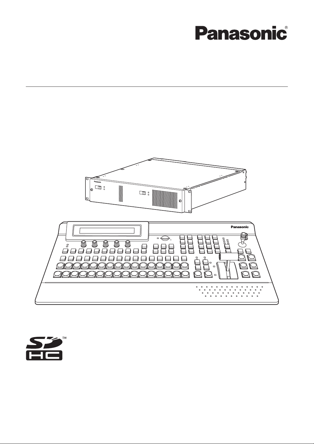
Mainframe
[AV-HS450U1N]
Operating Instructions
Multi-format Live Switcher
Model No. AV-HS450N
POWER1
OFF
ON
POWER1
ALARM1
POWER
ALARM
POWER2
OFF
ON
POWER2
ALARM2
Multi-format Live Switcher AV-HS450
Multi-format
Live
Switcher
AV-HS4 50
Control panel [AV-HS450C1N]
Before operating this product, please read the instructions carefully and save this manual for
future use.
Printed in Japan 3TR006327AAC
Safety precautions
CAUTION
RISK OF ELECTRIC SHOCK
DO NOT OPEN
CAUTION: TO REDUCE THE RISK OF ELECTRIC SHOCK,
REFER TO SERVICING TO QUALIFIED SERVICE PERSONNEL.
DO NOT REMOVE COVER (OR BACK).
NO USER SERVICEABLE PARTS INSIDE.
The lightning flash with arrowhead
symbol, within an equilateral triangle, is
intended to alert the user to the presence
of uninsulated “dangerous voltage” within
the product’s enclosure that may be of
sufficient magnitude to constitute a risk of
electric shock to persons.
The exclamation point within an equilateral
triangle is intended to alert the user to
the presence of important operating and
maintenance (service) instructions in the
literature accompanying the appliance.
WARNING:
THIS APPARATUS MUST BE EARTHED
To ensure safe operation, the three-pin plug must
be inserted only into a standard three-pin power
point which is effectively earthed through the
normal household wiring.
Extension cords used with the apparatus must have
three cores and be correctly wired to provide
connection to the earth. Wrongly wired extension
cords are a major cause of fatalities.
The fact that the apparatus operates satisfactorily
does not imply that the power point is earthed or
that the installation is completely safe. For your
safety, if you are in any doubt about the effective
earthing of the power point, please consult a
qualified electrician.
CAUTION:
TO REDUCE THE RISK OF FIRE OR SHOCK
HAZARD AND ANNOYING INTERFERENCE,
USE THE RECOMMENDED ACCESSORIES
ONLY.
FCC Note:
This equipment has been tested and found
to comply with the limits for a class A digital
device, pursuant to Part 15 of the FCC Rules.
These limits are designed to provide reasonable
protection against harmful interference when
the equipment is operated in a commercial
environment. This equipment generates, uses,
and can radiate radio frequency energy, and
if not installed and used in accordance with
the instruction manual, may cause harmful
interference to radio communications. Operation
of this equipment in a residential area is likely to
cause harmful interference in which case the user
will be required to correct the interference at his
own expense.
Warning:
To assure continued FCC emission limit
compliance, the user must use only shielded
interface cables when connecting to external
units. Also, any unauthorized changes or
modifications to this equipment could void the
user’s authority to operate it.
CAUTION:
In order to maintain adequate ventilation, do
not install or place this unit in a bookcase,
built-in cabinet or any other confined space.
To prevent risk of electric shock or fire hazard
due to overheating, ensure that curtains
and any other materials do not obstruct the
ventilation.
For CANADA
This class A digital apparatus complies
with Canadian ICES-003.
Cet appareil numérique de la classe A est
conforme à la norme NMB-003 du Canada.
WARNING:
• TO REDUCE THE RISK OF FIRE OR
ELECTRIC SHOCK, DO NOT EXPOSE THIS
APPARATUS TO RAIN OR MOISTURE.
• THE APPARATUS SHALL NOT BE EXPOSED
TO DRIPPING OR SPLASHING AND THAT
NO OBJECTS FILLED WITH LIQUIDS, SUCH
AS VASES, SHALL BE PLACED ON THE
APPARATUS.
indicates safety information.
The socket outlet shall be installed near the
equipment and easily accessible or the mains plug
or a power switch shall remain readily operable.
A warning that an apparatus with CLASS I
construction shall be connected to a MAINS
socket outlet with a protective earthing connection.
2

Safety precautions
IMPORTANT SAFETY INSTRUCTIONS
Read these operating instructions carefully before using the unit. Follow the safety instructions on the
unit and the applicable safety instructions listed below. Keep these operating instructions handy for future
reference.
1) Read these instructions.
2) Keep these instructions.
3) Heed all warnings.
4) Follow all instructions.
5) Do not use this apparatus near water.
6) Clean only with dry cloth.
7) Do not block any ventilation openings. Install
in accordance with the manufacturer’s
instructions.
8) Do not install near any heat sources
such as radiators, heat registers, stoves, or
other apparatus (including amplifiers) that
produce heat.
9) Do not defeat the safety purpose of the
polarized or grounding-type plug. A polarized
plug has two blades with one wider than the
other. A grounding-type plug has two blades
and a third grounding prong. The wide blade or
the third prong are provided for your safety. If
the provided plug does not fit into your outlet,
consult an electrician for replacement of the
obsolete outlet.
10)
Protect the power cord form being walked on or
pinched particularly at plugs, convenience
receptacles, and the point where they exit from
the apparatus.
11) Only use attachments/accessories specified by
the manufacturer.
12) Use only with the cart, stand,
tripod, bracket, or table specified
by the manufacturer, or sold with
the apparatus. When a cart is
used, use caution when moving
the cart/apparatus combination to
avoid injury from tip-over.
13) Unplug this apparatus during lightning storms
or when unused for long periods of time.
14) Refer all servicing to qualified service
personnel. Servicing is required when the
apparatus has been damaged in any way, such
as power-supply cord or plug is damaged,
liquid has been spilled or objects have fallen
into the apparatus, the apparatus has been
exposed to rain or moisture, does not operate
normally, or has been dropped.
indicates safety information.
<For USA-California Only>
This product contains a CR Coin Cell Lithium Battery which contains Perchlorate Material – special handling
may apply.
See www.dtsc.ca/gov/hazardouswaste.perchlorate.
3

Contents
Description ................................................7
Features .....................................................7
Configuration ............................................9
Accessories ..............................................9
Precautions for use ................................10
Tra demarks and
Registered T rademarks .....................11
Disclaimer of Warranty ...........................11
1. Installation ...........................................12
1-1. Installing the control panel...............................12
1-2. Installing the mainframe ..................................13
1-3. How to install the option boards ......................14
1-4. Connections ....................................................16
1-4-1. Block diagram ...........................................16
1-4-2. Co nnections when implementing gen-lock
(frame synchronizer OFF) ....................17
1-4-3. Co nnections when not implementing gen-
lock (frame synchronizer ON) ..............18
2. Functions in each area .......................19
2-1. Control panel ...................................................19
2-1-1. Crosspoint area ........................................20
2-1-2. Wipe pattern/memory area .......................21
2-1-3. User button area .......................................22
2-1-4. Transition area ..........................................22
2-1-5. LCD menu area ........................................25
2-1-6. Positioner area ..........................................27
2-1-7. SD memory card area ..............................28
2-1-8. Rear panel connections area ....................29
2-2. Mainframe .......................................................30
2-2-1. Front panel ................................................30
2-2-2. Rear panel connections area ....................31
3. Basic operations .................................33
3-1. Background transition ......................................33
3-1-1. Selecting the bus ......................................33
3-1-2. Se lecting the bus using the
SHIFT function .....................................33
3-1-3. Selecting the bus mode ............................36
3-1-4. Selecting the transition mode ...................37
3-1-5. Manual transition (using the fader lever) ...37
3-1-6. Auto transition ...........................................37
3-1-7. Cut transition .............................................37
3-2. IMAGE .............................................................38
3-2-1. Setting the IMAGE effects.........................38
3-2-2. Executing the IMAGE effect ......................39
3-3. Wipe ................................................................40
3-3-1. Selecting the wipe pattern ........................40
3-3-2. Se lecting the background for the
3D2 pattern page .................................42
3-3-3. Selecting the wipe direction ......................42
3-3-4. Wipe decorations (border, soft effect) .......43
3-3-5. Setting the wipe start position ...................44
3-3-6. Modifying wipe ..........................................45
3-4. Key ..................................................................47
3-4-1. Selecting the key type ...............................48
3-4-2. Selecting the key material .........................49
3-4-3. Key transitions ..........................................50
3-4-4. Key preview...............................................51
3-4-5. Ad justing the luminance key
and linear key .......................................52
3-4-6. Adjusting the chroma key .........................53
3-4-7. Key decorations ........................................61
3-4-8. Masking the key signals ............................62
3-4-9. Flying key ..................................................63
3-5. PinP (picture in picture) ...................................64
3-5-1. Se lecting the PinP channel
and material .........................................64
3-5-2. Selecting Shape........................................65
3-5-3. PinP preview .............................................65
3-5-4. PinP transitions .........................................66
3-5-5. PinP adjustments ......................................66
3-5-6. Linking PinP1 and PinP2 ..........................68
3-5-7. PinP decorations .......................................69
3-5-8. Trimming settings ......................................70
4

Contents
3-6. DSK (downstream key)....................................71
3-6-1. Selecting the DSK type .............................71
3-6-2. Se lecting the DSK channel and
DSK fill material ....................................73
3-6-3. DSK transitions .........................................74
3-6-4. DSK preview .............................................74
3-6-5. DSK adjustments ......................................75
3-6-6. DSK decorations .......................................76
3-6-7. Masking the DSK signals ..........................77
3-7. FTB (fade to black) ..........................................78
3-8. Internal color signals .......................................79
3-8-1. Setting the color background ....................79
3-9. Switching the AUX output ................................80
3-9-1. Selecting the AUX output materials ..........80
3-9-2. AUX1 transitions .......................................81
3-9-3. Se tting enable/disable for the
AUX1 transition.....................................82
3-10. Memory .........................................................83
3-10-1. Memory registration and recall items ......84
3-10-2. St oring the settings in the
memory (Store) ...................................85
3-10-3. R ecalling the operations stored in the
memory (Recall) ...................................86
3-10-4. D eleting the operations stored in the
memory (Delete) ..................................87
3-10-5. Effect dissolve .........................................88
3-11. Frame memories ...........................................89
3-11-1. Transferring images from the AUX bus ...89
3-11-2. Saving Images in Flash Memory ............90
3-12. SD memory cards .........................................91
3-12-1. Initializing the SD memory cards ............92
3-12-2. Saving data on SD memory cards ..........93
3-12-3. Loading data from SD memory cards .....94
3-12-4. Deleting files on SD memory cards ........95
3-12-5. Di splaying the SD memory card
information...........................................95
4. Input/output signal settings...............96
4-1. Input signal settings.........................................96
4-1-1. Setting the frame synchronizer .................97
4-1-2. Setting the input mode ..............................98
4-1-3. Freezing the input signals .........................99
4-1-4. Color corrector ........................................100
4-1-5. Setting the up-converter .........................104
4-1-6. Setting the analog input gain (option) .....105
4-1-7. Se tting the analog composite input signals
(option) ...............................................106
4-2. Setting the DVI input signals (option) ............107
4-2-1. Setting the DVI input signals ...................107
4-2-2. Adjusting the DVI input signals ...............111
4-3. Setting the output signals ..............................112
4-3-1. Assigning the output signals ...................113
4-4. Se tting the DVI output signals
(OUT5 and OUT6 standard outputs and
options) .....................................................115
4-5. Setting the down-converter (option) ..............117
4-6. Setting the sync signals.................................118
4-7. Adjusting the output signal phase .................119
4-8. Setting the multi view display ........................123
4-8-1. Setting the screen layout ........................123
4-8-2. Setting the split frame and characters ....125
4-8-3. Setting the tally displays .........................126
4-8-4. Changing the material names .................127
4-8-5. High-resolution multi view mode .............128
4-9. Setting the on-screen display (OSD) .............129
4-10. Setting the ancillary data .............................130
5

Contents
5. System settings ................................131
5-1. Selecting the video format .............................131
5-2. Setting the crosspoints ..................................132
5-2-1. Assigning signals to the crosspoints .......132
5-2-2. Setting the crosspoint switching .............134
5-3. Button assignments .......................................135
5-3-1. Setting the user buttons ..........................135
5-4. Setting the date and time ..............................137
5-5. Network settings ............................................138
5-6. Other settings ................................................139
5-7. External device control ..................................140
5-7-1. En able/Disable Setting for Control of
External Devices ................................140
5-7-2. Editor control...........................................141
5-7-3. Setting the GPI .......................................142
5-7-4. Camera control .......................................144
5-8. Status displays ..............................................151
5-8-1. Alarm status displays ..............................151
5-8-2. Alarm message .......................................151
5-8-3. Di splaying the version information and
option information ................................152
5-9. Initialization....................................................153
5-9-1. Initializing Setting Data ...........................153
5-9-2. Initializing Fader ......................................153
6. External interfaces ...........................154
6-1. Co nnecting the control panel
and mainframe ..........................................154
6-2. Mainframe .....................................................154
6-2-1. LAN .........................................................154
6-2-2. EDITOR ..................................................155
6-2-3. COM .......................................................155
6-2-4. TALL Y/GPI ...............................................156
6-3. Control panel .................................................157
6-3-1. TALL Y/GPI ...............................................157
7. Image transmission functions .........158
8. Setting menu table ............................163
9. Appearance .......................................181
10. Specifications .................................182
Appendix (glossary) .............................187
6

Description
This is a 1 ME digital video switcher which supports a multiple number of HD and SD formats.
It consists of a mainframe and control panel.
Despite its compact dimensions of 2RU, the mainframe comes with 16 inputs and four outputs for SDI under the
standard specifications.
It also supports two DVI outputs, and its video effects of one key line, two DSK lines, two PinP lines, two DVE
(BKGD) lines, one DVE (key) line and two multi view lines enable video productions in a wide variety of forms.
Incorporated in the switcher’s inputs are a frame synchronizer, up-converter and color corrector.
When the option boards are installed, a wider variety of input/output formats including analog composite, analog
component and DVI can be accommodated so that systems can be constructed flexibly.
Features
Compact design, wide variety of input/output signals
The mainframe, despite its compact dimensions of 2RU, comes with a wide variety of input/output facilities in
the standard configuration.
As input facilities, a total of 16 HD/SD-SDI signal lines are supported under the standard specifications, and a
frame synchronizer is incorporated for all the inputs. Also incorporated are four up-converter signal lines and
eight color corrector signal lines.
The output facilities include four HD/SD-SDI signal lines and two DVI-D signal lines under the standard
specifications.
Two option slots each for input/output applications are provided.
When two option boards for input applications are installed, the maximum number of input signal lines can be
expanded to 20; similarly, when two option boards for output applications are installed, the maximum number of
output signal lines can be increased to 10.
Multiple formats supported
The signal formats supported include HD formats (1080/59.94i, 1080/50i, 1080/24PsF
720/59.94p and 720/50p), SD formats (480/59.94i and 576/50i) and DVI
1: The following option boards are not supported:
AV-HS04M1, AV-HS04M2, AV-HS04M3, AV-HS04M4, AV-HS04M5,
AV-HS04M6, AV-HS04M7
2: The standard DVI output is the DVI-D signal output.
The AV-HS04M3 option board supports DVI-I signal input, the AV-HS04M8 option board supports DVI-D
signal input, and the AV-HS04M5 supports DVI-I signal output.
Multi view display function
Two multi view display function lines are provided under the standard specifications.
It is possible to divide up to 20 lines of video including program video (PGM), preview video (PVW) and input
video signals between two screens and display them at the same time on two monitors.
Frame synchronizer system and external synchronization system supported
A high-performance 10-bit frame synchronizer is incorporated for all the inputs so that asynchronous video
signals can be input. By using the black burst (BB) output, it is possible to construct a system referenced to the
synchronization of the switcher.
A genlock function is provided so that external synchronization systems using external sync signals (BB or TRI
signals) as a reference are also supported.
2
.
1
, 1080/23.98PsF 1,
7

Features
Many different effect functions incorporated
Along with the standard wipe, mix and cut functions, the switcher can provide size reduction, slide and other
DVE transitions.
DVE transitions using the 2-screen push-out effect and other 2-channel functions are possible.
The unit comes with luminance keys and chroma keys provided as keyers as well as specialized hardware in
the form of two DSK lines and two PinP lines as a standard option.
AUX1 is equipped with a mix transition function.
This enables MIX transitions with the material selected next, allowing for a flexible system construction.
High-quality chroma keys using Primatte
The Primatte
®
algorithm, which has proven to be very popular in many non-linear editors as a plug-in software,
®
algorithms
has been put to practical use in a linear editing system for the chroma keys. High chroma key image quality can
be achieved through some simple operations.
Primatte® is a registered trademark of IMAGICA DIGIX Inc.
The copyrights of Primatte
The patents for Primatte
®
belong to IMAGICA DIGIX Inc.
®
belong to IMAGICA DIGIX Inc.
SDHC memory cards supported
Still image data (BMP, JPEG) can be imported from SDHC memory cards into the unit’s frame memories for use
as background images or key materials.
In addition, the images and setting data in the unit’s frame memories can be stored on the SDHC memory
cards.
SDHC Logo is a trademark.
Pan-tilt head system (pan-tilt head and convertible camera) control supported
Using the COM connector, a Panasonic pan-tilt head system (with pan, tilt, zoom, focus and preset functions)
can be controlled.
When a controller is used, up to five pan-tilt head systems can be controlled.
Camera menu operations can also be performed.
Controllers supported AW-RP555N, AW-RP655N
Pan-tilt heads supported AW-PH400P, AW-PH405N, AW-PH360N
Camera supported AW-HE100N
Redundant power supply
Under the standard specifications, a redundant power supply is provided so that live operations can be
undertaken with complete peace of mind.
Simple operability
Live transmissions can be delivered speedily thanks to the 16 crosspoint buttons and pattern selection buttons
and other controls on the panel with its simple layout that enables various functions to be operated directly.
Preset-like operations are performed using menus appearing on the unit’s LCD display or on the on-screen
displays.
8

Configuration
Mainframe [AV-HS450U1N] .............................................................................. 1
Control panel [AV-HS450C1N] .......................................................................... 1
Accessories
Operating instructions ....................................................................................... 1
CD-ROM (Operating instructions/Image transmission software) ...................... 1
AC adapters (for control panel) ......................................................................... 2
Power cords (for mainframe and AC adapter) .................................................. 4
CAT5E cable (STP, straight cable, 10 m long) .................................................. 1
Optional boards (sold separately)
Board Model number Function
SDI Input Board AV-HS04M1
Analog Input Board AV-HS04M2
DVI Input Board AV-HS04M3
Analog Output Board AV-HS04M4
DVI/Analog Output Board AV-HS04M5
Analog Composite Input Board AV-HS04M6
SDI Output Board AV-HS04M7
Full-HD DVI Input Board AV-HS04M8
Option boards are installed in the two input/output option slots (slot A, slot B).
SDI input 2 lines
Analog component input 2 lines
DVI-I input 2 lines
Analog component output 2 lines
DVI-I output 1 line
Analog component output 1 line
Analog composite input 2 lines
SDI output 2 lines
DVI-D input 2 line
9

Precautions for use
Handle carefully.
Do not drop the product, or subject it to strong shock or vibration.
Do not carry or move the product by the fader lever. This is important to prevent trouble.
Use the product in an ambient temperature of 32 °F to 104 °F (0 °C to 40 °C).
Avoid using the product at a cold place below 32 °F (0 °C) or at a hot place above 104 °F (40 °C) because
extremely low or high temperature will adversely affect the parts inside.
Power off before connecting or disconnecting cables.
Before plugging or unplugging the cables, be sure to switch power off.
Avoid humidity and dust.
Avoid using the product at a humid, dusty place because much humidity and dust will cause damage to the
parts inside.
Maintenance
Wipe the product using a dry cloth. To remove stubborn dirt, dip a cloth into a diluted solution of kitchen
detergent (neutral), wring it out well, and wipe the product gently. Then, after wiping the product with a moist
cloth, wipe it again with a dry cloth.
Caution
• Avoid using benzine, paint thinners and other volatile fluids.
• If a chemical cleaning cloth is to be used, carefully read through the precautions for its use.
Precaution to be observed during production
This product’s image switching and image effect functions can be used to produce images which flicker rapidly
or images which change rapidly.
However, bear in mind when using these functions in production that the kinds of images produced may have
an adverse effect on the viewer’s physical well-being.
Handling the optional boards
Be absolutely sure to turn off the power of the product before installing or removing any of the optional boards.
Furthermore, when installing or removing the optional boards, take care not to hurt yourself on the edges and
metal parts of the boards.
When the product is to be discarded
When the product is to be discarded at the end of its service life, ask a specialized contractor to dispose of it
properly in order to protect the environment.
Concerning the consumable parts
Cooling fan:
This is a consumable part. As a general rule, replace it every 5 years or so (when the unit has been
operated for 15 hours a day).
Power supply unit:
This is a consumable part. As a general rule, replace it every 5 years or so (when the unit has been
operated for 15 hours a day).
The period when the consumable parts need to be replaced will differ depending on the operating conditions.
When the time comes to replace one of these parts, be absolutely sure to ask your dealer to do the job.
10

Precautions for use
Trademarks and Registered Trademarks
Microsoft and Windows are either registered trademarks or trademarks of Microsoft Corporation in the United
States and other countries.
Adobe and Reader are either registered trademarks or trademarks of Adobe Systems Incorporated in the
United States and/or other countries.
SDHC logo is a trademark.
Other names of companies and products contained in these operating instructions may be trademarks or
registered trademarks of their respective owners.
Disclaimer of Warranty
IN NO EVENT SHALL Panasonic Corporation BE LIABLE TO ANY PARTY OR ANY PERSON, EXCEPT FOR
REPLACEMENT OR REASONABLE MAINTENANCE OF THE PRODUCT, FOR THE CASES, INCLUDING BUT
NOT LIMITED TO BELOW:
ANY DAMAGE AND LOSS, INCLUDING WITHOUT LIMITATION, DIRECT OR INDIRECT, SPECIAL,
CONSEQUENTIAL OR EXEMPLARY, ARISING OUT OF OR RELATING TO THE PRODUCT;
PERSONAL INJURY OR ANY DAMAGE CAUSED BY INAPPROPRIATE USE OR NEGLIGENT
OPERATION OF THE USER;
UNAUTHORIZED DISASSEMBLE, REPAIR OR MODIFICATION OF THE PRODUCT BY THE USER;
INCONVENIENCE OR ANY LOSS ARISING WHEN IMAGES ARE NOT DISPLAYED, DUE TO ANY
REASON OR CAUSE INCLUDING ANY FAILURE OR PROBLEM OF THE PRODUCT;
ANY PROBLEM, CONSEQUENTIAL INCONVENIENCE, OR LOSS OR DAMAGE, ARISING OUT OF THE
SYSTEM COMBINED BY THE DEVICES OF THIRD PARTY;
INCONVENIENCE, DAMAGE, OR LOSS RESULTING FROM ACCIDENTS CAUSED BY AN INADEQUATE
INSTALLATION METHOD OR ANYTHING OTHER THAN A DEFECT IN THE PRODUCT;
LOSS OF REGISTERED DATA CAUSED BY ANY FAILURE.
ANY DAMAGE OR CLAIMS DUE TO LOSS OR LEAKAGE OF IMAGE DATA OR SETTING DATA SAVED
ON THIS UNIT OR ON AN SD CARD OR PC.
11
1. Installation
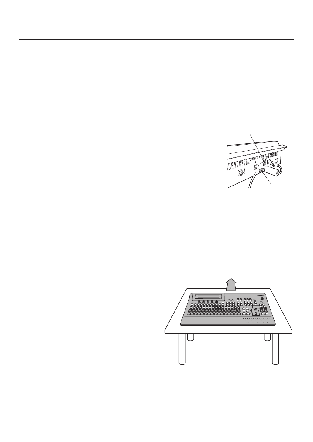
1-1. Installing the control panel
Follow the instructions set forth in “Safety precautions” and also observe the
cautionary items below.
Be absolutely sure to ask your dealer to do the jobs of installing and connecting the panel.
Connecting the power supply
Be absolutely sure to use only the power cord and AC adapter supplied with the
panel.
Be absolutely sure to connect the grounding terminal of the power cord to
ground.
Also connect the ground terminal (SIGNAL GND) at the rear of the panel to the
system ground.
If only one AC adapter is to be connected, place the dust-proof cap over the DC
power input socket that is not going to be used.
To prevent the DC plug from being disconnected, secure the cable of the AC
adapter to the cable clamp.
When the control panel is not going to be used for a prolonged period of time,
set its power switch to the “off” position to conserve power, and disconnect the
power plug.
Handle the control panel carefully!
Dropping the control panel or subjecting it to strong impact or vibration may cause trouble and/or malfunctioning.
Dust-proof cap
LCD CONTRAST
MAINFRAME
Cable clamp
POWER
OFF
ON
IN2
12V
IN1
12V
Do not allow any foreign objects to enter inside the control panel!
Allowing water, metal items, scraps of food or other foreign objects inside the control panel may cause a fire
and/or electric shocks.
Choosing the best installation location
This unit is designed for indoor use only.
Install the unit on a sufficiently strong, stable and level
surface for use.
Ensure a space of at least 100 mm around the rear
Ventilation holes
vents to avoid obstructing ventilation.
In particular, ensure sufficient space between
ventilation and wiring when using mounted in a panel
Multi-format
Live
Switcher
or table.
Do not install the panel in a cold place where the
POWER
ALARM
AV-HS450
temperatures will drop below 32 °F (0 °C) or in a hot
place where the temperatures will rise above 104 °F
(40 °C).
Avoid installing the panel where it will be exposed to
direct sunlight or to the hot air that is blown out from
other products.
Installing the panel in a very humid, dusty or vibration-
prone location may give rise to trouble.
12
1. Installation
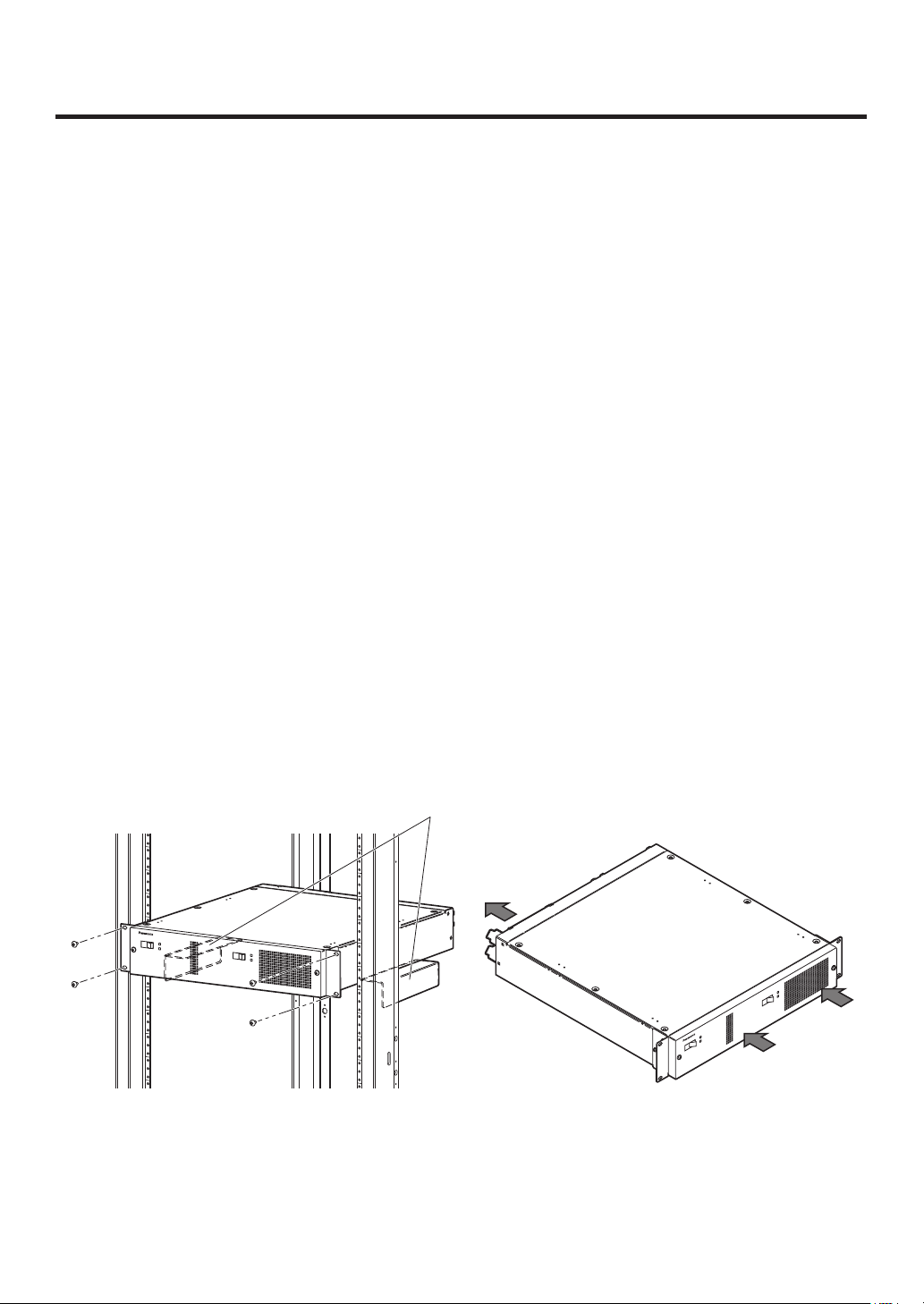
1-2. Installing the mainframe
Comply with the instructions set forth in “Safety precautions” and also observe
the cautionary items below.
Be absolutely sure to ask your dealer to do the jobs of installing and connecting the mainframe.
Connecting the power supply
Be absolutely sure to use the power cord supplied with the mainframe.
Be absolutely sure to connect the grounding terminal of the power cord to ground.
Handle the mainframe carefully!
Dropping the mainframe or subjecting it to strong impact or vibration may cause trouble and/or malfunctioning.
Do not allow any foreign objects to enter inside the mainframe!
Allowing water, metal items, scraps of food or other foreign objects inside the control panel may cause a fire
and/or electric shocks.
Choosing the best installation location
This unit is designed for indoor use only.
Mount the mainframe securely in a standard 19-inch rack (with a depth dimension of at least 600 mm) that
meets the EIA standard or its equivalent for use.
Install the mainframe securely using screws that are compatible with the rack.
Be absolutely sure to attach the support guides used to support the back part of the mainframe. (Provide
support guides that are compatible with the rack.)
Provide sufficient clearances from the area around the ventilation holes at the front and the cooling fan at the
back.
Do not install the mainframe in a cold place where the temperatures will drop below 32 °F (0 °C) or in a hot
place where the temperatures will rise above 104 °F (40 °C).
Avoid installing the mainframe where it will be exposed to direct sunlight or to the hot air that is blown out from
other products.
Installing the mainframe in a very humid, dusty or vibration-prone location may give rise to trouble.
POWER1
OFF
ON
POWER1
ALARM1
POWER2
OFF
Installation in a rack
Support guides
ON
POWER2
ALARM2
Multi-format Live Switcher AV-HS450
POWER1
ALARM1
POWER1
OFF ON
POWER2
R2
ON
ALARM2
POWE
OFF
Multi-format Live Switcher AV-HS450
Flow of air through the ventilation holes
13
1. Installation
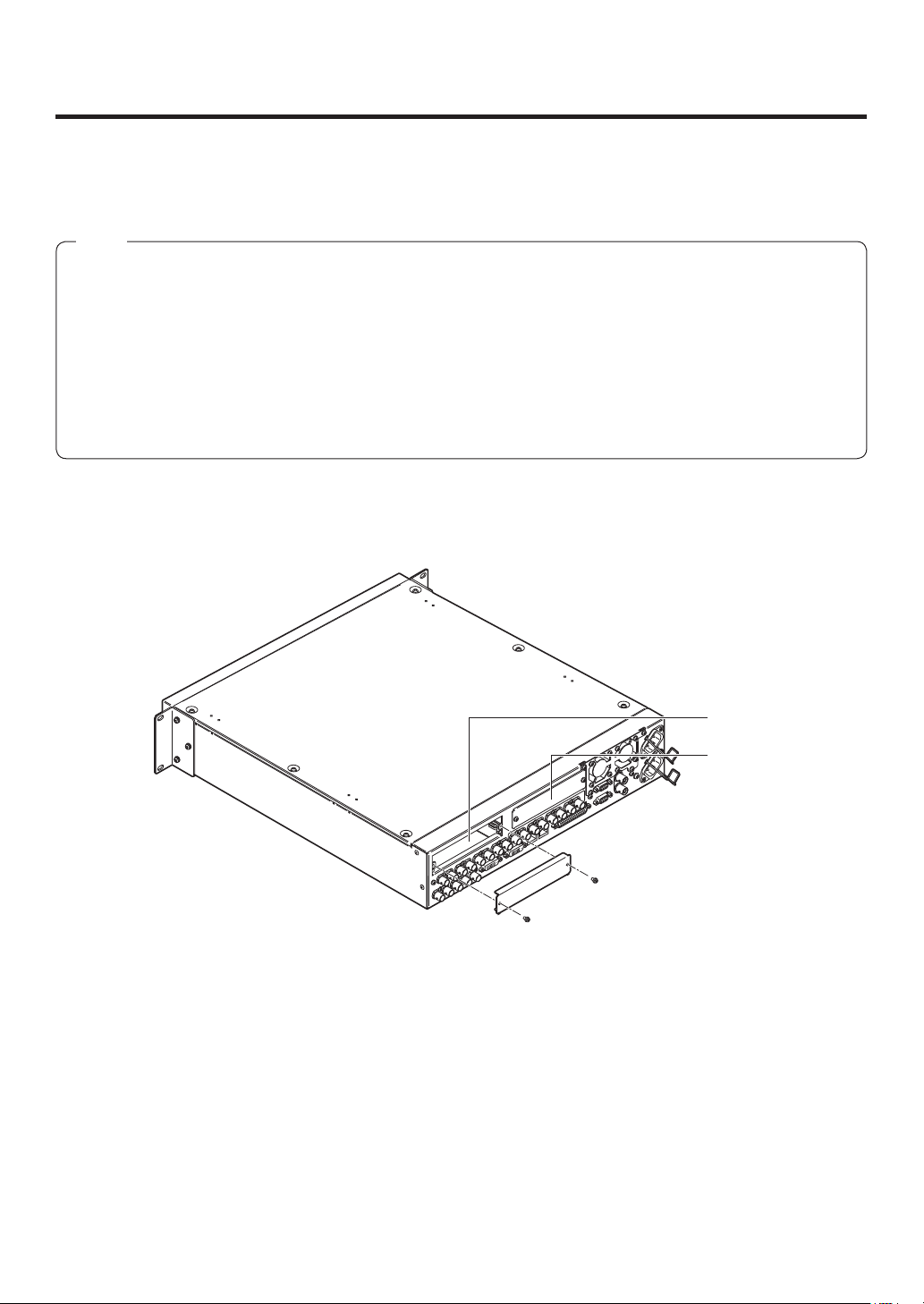
1-3. How to install the option boards
The option boards are installed in the mainframe.
For details, refer to the operating instructions of the option board concerned.
Notes
Be absolutely sure to ask your dealer to do the job of installing or removing the option boards.
Before installing or removing an option board, turn off the power, and disconnect the power plug.
Before coming into physical contact with the option board, touch your hand to metal that has been grounded
to discharge the static electricity in your body.
A safe way to proceed is to wear an anti-static wrist strap.
The option board may be damaged if you touch the board with static still in your body.
Avoid damage to the option board by not dropping it or subjecting it to strong shocks or vibrations.
After removing an option board, be absolutely sure to attach the blank panel.
When installing or removing an option board, take care not to hurt yourself on the edges or metal parts of the
board.
Turn off the power of the mainframe, and disconnect the power cord.
Loosen the two screws of SLOT A or SLOT B at the back of the mainframe, and remove the blank panel.
Screw
SLOT A
SLOT B
Blank panel
Screw
14
1. Installation
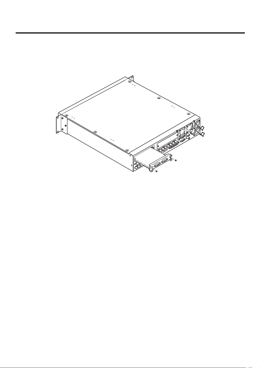
Align the option board with the guide rails, and insert it slowly.
Insert it until it will go no further. Take care not to exert excessive force while doing this since that may damage
the connector inside.
Mount the option board in place using the two screws.
Clamping torque: 0.7 N•m
DVI-D
UTS
DVI INP
DVI-D
Screw
Screw
After connecting the necessary cables, plug the power cord into the power outlet, and turn on the power.
15
1. Installation
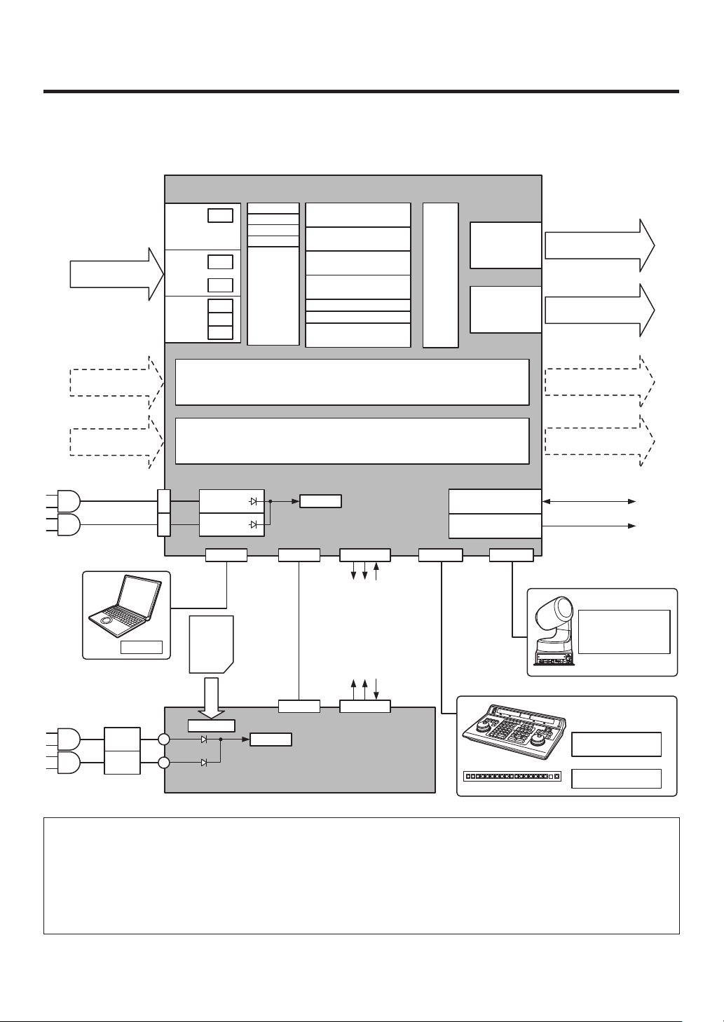
1-4. Connections
1-4-1. Block diagram
Mainframe
INPUT
1 to 8
INPUT (SDI)
1 to 16
INPUT
9 to 12
INPUT
13 to 16
FS
FS
CC
FS
UC
CC
Black
ColorBGD
ColorBar
FMEM1
MTX
CUT, MIX, WIPE, DVE2
to 4
CUT, MIX, WIPE, DVE
AUX1
BKGD
KEY
PinP1, 2
MIX
DSK1, 2
MIX
FTB
to 4
MV1, 2
Output
MTX
OUTPUT
1 to 4
OUTPUT
5, 6
OUTPUT (SDI)
1 to 4 (3)
OUTPUT (DVI-D)
5, 6
INPUT
A1, A2
INPUT
B1, B2
AC/DC
AC IN
PC
DC IN
AC/DC
RJ45
LAN
(5)
SD
memory
card
Control panel
Option slot A
Option slot B
PowerAC/DC
RJ45 Dsub 50 Dsub 9 Dsub 9
PANEL
(4)
RJ45 Dsub 25
PowerAC/DC
TALLY/GPI
ALARM: 1
GPI-OUT: 31
GPI-IN: 8
ALARM: 1
GPI-OUT: 8
GPI-IN: 8
TALLY/GPIMAINFRAME
EDITOR COM
REF IN/OUT (1)
REF OUT (2)
REF
OUTPUT
A1, A2
OUTPUT
B1, B2
Camera
Pan/Tilt Head
Controller
Editing
controller
Aux panel
1: When external synchronization is selected as the
reference signal setting, the reference signal is input.
When internal synchronization is selected, the reference
signal is output.
2: When external synchronization is selected as the
reference signal setting, the signals are looped through
and output. When internal synchronization is selected, the
reference signal is output.
3: Two sets of the same output signals are distributed from
OUTPUT (SDI) 1.
4: Connect the PANEL connector directly to the
MAINFRAME connector using the supplied CAT5E cable.
5: Do not connect to a public line when connecting a PC.
16
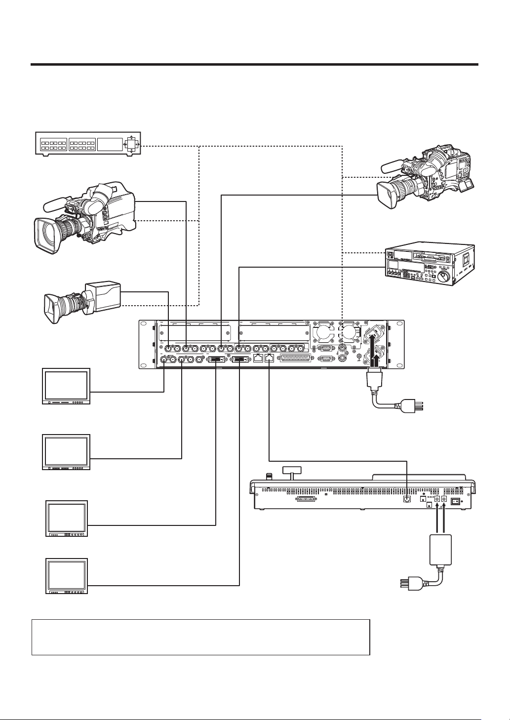
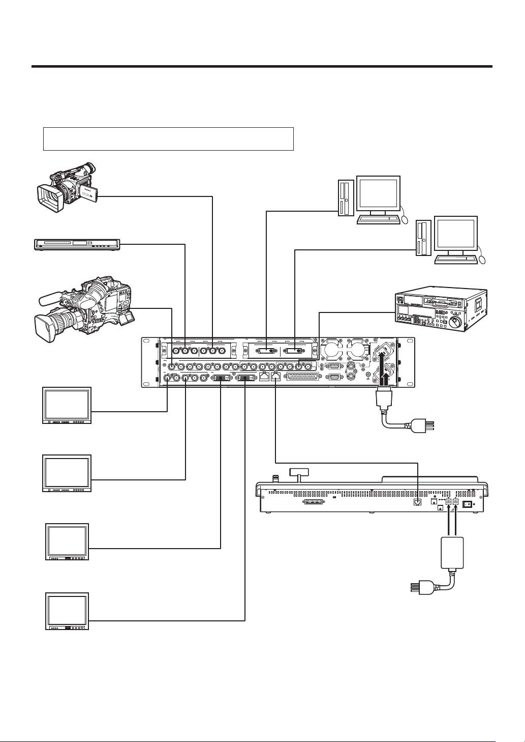
1. Installation
1-4-2. Connections when implementing gen-lock
(frame synchronizer OFF)
Sync Generator
HD camera
HD camera
HD camera
HD SDI monitor
HD SDI
HD SDI
HD SDI
HD SDI
SLOT A
SDI INPUTS
SDI OUTPUTS
1
IN/OUT A2IN/OUT A1
321 456789 10 11 12 13 14 15 16 C/C
DVI-D OUTPUTS
234 56
SLOT B
HD SDI
HD SDI
IN/OUT B2IN/OUT B1
U/C
TALLY/GPI
PANELLAN
Multi-format Live
Switcher
AV-HS450N
VTR
〜IN1
〜 IN2
EDITOR
COM
SIGNAL
GND
REF
Power cord
HD SDI monitor
NORMAL
SERVICE
TALLY / GPI MAINFRAME
DVI-D
PC monitor
DVI-D
PC monitor
When the unit is to be installed and when the connections are to be performed, be absolutely
sure to ask your dealer to be responsible for carrying out the work that needs to be done.
Use a 3-point power outlet as the power source in order to earth the unit securely.
17
AC adapter
LCD CONTRAST
12V IN 1
12V IN 2
POWER
OFFON
SIGNAL
GND
1. Installation
1-4-3. Connections when not implementing gen-lock
(frame synchronizer ON)
Example where the optional board is used
SLOT A: Analog Input Board (AV-HS04M2)
SLOT B: Full-HD DVI Input Board (AV-HS04M8)
HD Component
DVI-D
HD camera
PC
PC
DVD player
HD camera
HD SDI monitor
HD SDI monitor
HD SDI
HD SDI
HD Component
HD SDI
SLOT A
SDI INPUTS
SDI OUTPUTS
1
IN/OUT A2IN/OUT A1
ANALOG INPUTS
PbY
PbY
Pr
321456789 10 11 12 13 14 15 16 C/C
DVI-D OUTPUTS
234 56
SLOT B
Pr
DVI INPUTS
DVI-D DVI-D
PANELLAN
IN/OUT B2IN/OUT B1
Multi-format Live
Switcher
AV-HS450N
DVI-D
SD SDI
〜IN1
〜 IN2
SIGNAL
GND
REF
TALLY/GPI
U/C
EDITOR
COM
Power cord
NORMAL
SERVICE
TALLY / GPI MAINFRAME
VTR
LCD CONTRAST
12V IN 1
12V IN 2
POWER
OFFON
SIGNAL
GND
PC monitor
PC monitor
DVI-D
AC adapter
DVI-D
18
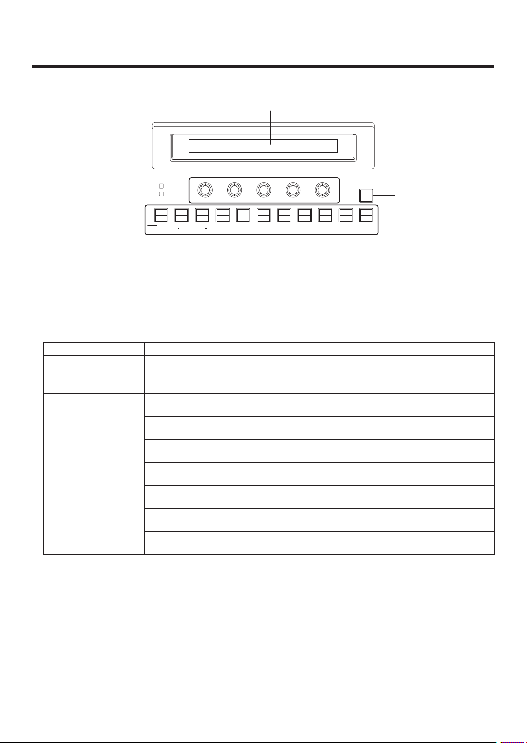
2. Functions in each area
2-1. Control panel
User button area
LCD menu area
POWER
ALARM
F1 F2 F3 F4 F5
PinP1
DSK1
KEY
CKEY
PinP2
DSK2
KEY PinP 1/2 DSK 1/2 AUX1 AUX2 AUX3 AUX4
AMBER:1 / GREEN :2
AUX
PGM/A
1/17 2/18 3/19 4/20 5/21 6/22 7/23 8/24 9/25 10/26 11/27 12/28 13/29 14/30 15/31 16/32
PST/B
IMAGE A
FMEM
CTL
TIME
BKGD
IMAGE B
CBGD
MENU FUNCTION / AUX BUS DELEGATION MEMORY / PATTERNUSER
SDCard
XPTMVIN
CAM
OUT
SD memory card area Positioner area
HOLD
123
CONFIG
SYS
456
Wipe pattern/memory area
Multi-format
STOR
RE
CALL
DEL
UNDO
BKGD KEY
MIX WIPE
CUT AUTOSHIFT
1243
123
56
456
789
789
10 12
11
10 XPT DSBL EFF DSLV
MIX
WIPE
ON
SHOT
MEM
BKGD
WIPE
MEM
MEM
MEM
SHIFT
SHIFT
PinP
CAM
WIPE
SQ1 SQ2
3D1 3D2
Live
Switcher
AV-HS4 50
PAGE
SL2SL1
BKGD
PATT
KEY
PATT
POSITIONER
N/R R
WIPE DIRECTION
KEYONFTB
PinP1ONPinP2
DSK1ONDSK2
Z
ON
ON
ON
Transition areaCrosspoint area
Power indicator [POWER]
This indicator lights when the power switch () on the rear panel is set to ON while power is supplied to the
DC power input socket.
It goes off when the power switch () is set to OFF.
Alarm indicator [ALARM]
This indicator lights when the mainframe’s cooling fan has stopped running or when there is a problem (voltage
drop) with the power supply of the mainframe or the control panel.
When this occurs, an alarm message is displayed on the LCD and on the OSD screen of the external monitor.
During the occurrence of an alarm, details of the trouble can be checked using the SYSTEM/Alarm menu.
Alarm information can be output to an external device from the control panel’s TALLY/GPI connector ().
For details, refer to “5-8-2. Alarm message”.
If the alarm goes off, stop using the unit immediately and be sure to contact your dealer.
Continuing to use the unit even after the alarm goes off could damage it.
19

2. Functions in each area
1/17 2/18 3/19 4/20 5/21 6/22 7/23 8/24 9/25 10/26 11/27 12/28 13/29 14/30 15/31 16/32
PGM/A
AUX
PST/B
KEY PinP 1/2 DSK 1/2 AUX1 AUX2 AUX3 AUX4
SHIFT
SHIFT
SHIFT
CAM
MEM
123
456
KEY
MENU FUNCTION / AUX BUS DELEGATION USER
CKEY
BKGD
PinP1
PinP2
DSK1
DSK2
TIME
CBGD
IMAGE A
IMAGE B
FMEM
SDCard
CTL
CAM
XPTMVIN
OUT
CONFIG
SYS
AMBER:1 / GREEN :2
2-1-1. Crosspoint area
PGM/A bus crosspoint buttons [PGM/A 1 to 32]
These are used to select the PGM/A bus video signals.
Buttons 1 to 32 can be selected using the [SHIFT] button.
Refer to “3-1-2. Selecting the bus using the SHIFT function”.
In the case of the flip-flop system, the main line video (PGM) signals are always selected.
When one of the crosspoint buttons (, , ) is held down, the name of the input material and the number of
the crosspoint button are displayed.
PST/B bus crosspoint buttons [PST/B 1 to 32]
These are used to select the PST/B bus video signals.
Buttons 1 to 32 can be selected using the [SHIFT] button.
Refer to “3-1-2. Selecting the bus using the SHIFT function”.
In the case of the flip-flop system, the images inserted next (PST) are always selected.
AUX bus selector buttons [KEY, PinP 1/2, DSK 1/2, AUX1 to AUX4]
Select the bus to be operated using the AUX bus crosspoint buttons ().
The selected button lights.
[KEY]:
This button is used to change the AUX bus crosspoint buttons () into the selector buttons for the sources
of the key fill buses.
The source for the key source bus can be set using the menu displayed when the AUX bus crosspoint
buttons () are held down. The set source will be the same for DSK1 and DSK2.
The source can also be set from the CONFIG menu.
[PinP 1/2]:
This button is used to change the AUX bus crosspoint buttons () into the selector buttons for the sources
of the PinP buses.
Each time it is pressed, its target is switched between PinP1 and PinP2.
When PinP1 is selected, the button lights in amber; when PinP2 is selected, it lights in green.
[DSK 1/2]:
This button is used to change the AUX bus crosspoint buttons () into the selector buttons for the sources
of the DSK fill buses.
Each time it is pressed, its target is switched between DSK1 and DSK2.
When DSK1 is selected, the button lights in amber; when DSK2 is selected, it lights in green.
[AUX1] - [AUX4]:
These buttons are used to change the AUX bus crosspoint buttons () into the selector buttons for the
sources of the AUX buses.
The AUX bus selector buttons are also used as the menu function buttons ().
20
2. Functions in each area
123
456
789
10 XPT DSBL EFF DSLV
WIPE
SQ1 SQ2
SL2SL1
3D1 3D2
PAGE
STOR
DEL
UNDO
BKGD
WIPE
MEM
RE
CALL
SHOT
MEM
PinP
MEM
CAM
MEM
BKGD
PATT
KEY
PATT
1243
56
789
10 12
MEMORY / PATTERN
11
AUX bus crosspoint buttons
These buttons are used to select the source of the bus which was selected by the AUX bus selector button ().
Buttons 1 to 32 can be selected using the [SHIFT] button.
Refer to “3-1-2. Selecting the bus using the SHIFT function”.
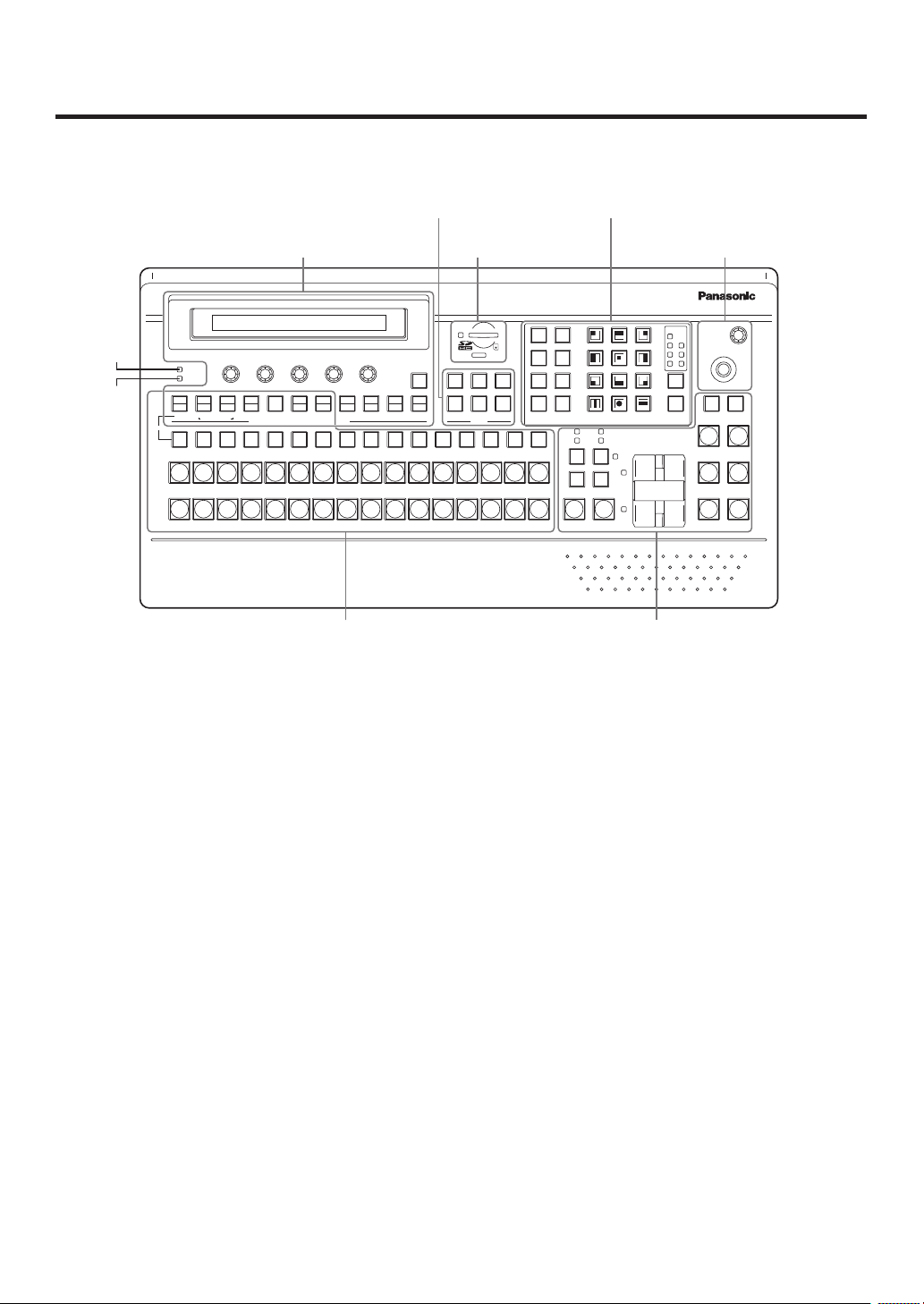
2-1-2. Wipe pattern/memory area
Wipe pattern and memory selector buttons
Wipe patterns 1 to 12 can be selected while the BKGD and KEY
pattern selector buttons () are lighted.
Data can be stored in the memories of buttons 1 to 10 or
recalled from these memories while one of the memory
operation buttons () — [SHOT MEM], [BKGD WIPE MEM],
[PinP MEM] or [CAM MEM] — is lighted.
BKGD, KEY pattern selector buttons [BKGD PATT] [KEY PATT]
Press the [BKGD PATT] button, and while it is lighted, select the wipe pattern for the background transition.
Similarly, press the [KEY PATT] button, and while it is lighted, select the wipe pattern for the key transition.
Each time the [BKGD PATT] button and [KEY PATT] button are pressed, the pattern page changes in the
following sequence: WIPE, SQ1 (squeeze 1), SL1 (slide 1), 3D1 (3 dimensions 1), SQ2 (squeeze 2), SL2
(slide 2) and 3D2 (3 dimensions 2). Which pattern page has been selected can be checked by observing which
pattern page indicator LED () is lighted.
SQ2, SL2, and 3D2 may not be selected as the wipe pattern for the key transition.
Pattern page indicator LEDs [PAGE]
By observing which pattern page indicator LED is lighted, it is possible to check which pattern page has been
selected by the BKDG PATT or KEY PATT selector button ().
Memory operation buttons [SHOT MEM] [BKGD WIPE MEM] [PinP MEM] [CAM MEM]
[STOR] [RECALL] [DEL] [UNDO]
Press the [SHOT MEM], [BKGD WIPE MEM], [PinP MEM] or [CAM MEM] button to perform the memory
operations for the number keys (1 to 10).
[STOR]:
Press this to register data in the memory.
[RECALL]:
Press this to recall data from the memory.
[DEL]:
Press this to delete data in the memory.
[UNDO]:
Press this to undo the operation of the [RECALL] or [DEL] button.
The number of operations that can be undone is one only.
This operation cannot be performed using memory operations when the [CAM MEM] button has been
pressed.
21
2. Functions in each area
123
456
USER
8 9
10 XPT DSBL EFF DSLV
MIX
WIPE
ON
DSK1ONDSK2
ON
PinP1ONPinP2
ON
KEYONFTB
ON
N/R R
BKGD KEY
MIX WIPE
CUT AUTO
KEY
PATT
10 12
MEMORY / PATTERN
11
WIPE DIRECTION
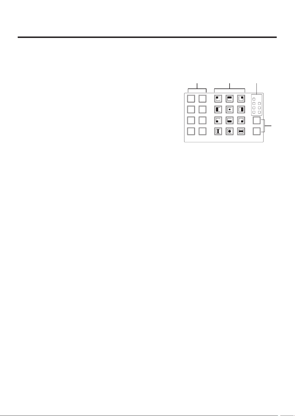
2-1-3. User button area
User buttons [USER1 to USER6]
These are used to assign some functions of the menu settings to the [USER1]
to [USER6] buttons on the CONFIG menu.
See “5-3-1. Setting the user buttons”.
2-1-4. Transition area
[BKGD] button
This executes the background transition when the [AUTO] button () or fader lever () has been operated.
When the [BKGD] button is pressed and it is selected, its indicator lights in amber.
If the [KEY] button () is now pressed, the indicator goes off, and the de-selected status is established.
When the [BKGD] button and [KEY] button () are pressed at the same time, both buttons are set to the
selected status.
[KEY] button
This executes the key transition when the [AUTO] button () or fader lever () has been operated.
When the [KEY] button is pressed and it is selected, its indicator lights in amber.
If the [BKGD] button () is now pressed, the indicator goes off, and the de-selected status is established.
When the [BKGD] button () and [KEY] button are pressed at the same time, both buttons are set to the
selected status.
KEY ON tally LED
This lights in red when the key ON status is established.
MIX, WIPE selection status tally LEDs
These light up to indicate whether MIX or WIPE has been selected when background transitions or key
transitions are executed.
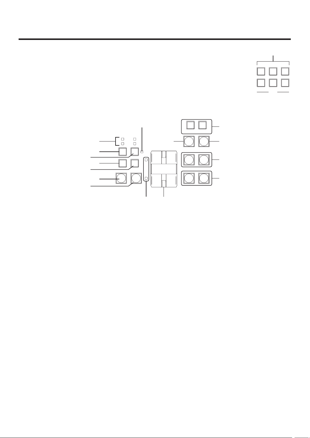
22

2. Functions in each area
[MIX] button
This is used to switch the A and B bus images while making them overlap.
During the transition, the A and B bus output total is kept at 100 %.
When the [MIX] button is pressed and it is selected, its indicator lights in amber.
If the [WIPE] button () is now pressed, it goes off, and the de-selected status is established.
[WIPE] button
This is used to execute the transition using the pattern selected by the wipe pattern selector button ().
When the [WIPE] button is pressed and it is selected, its indicator lights in amber.
If the [MIX] button () is now pressed, it goes off, and the de-selected status is established.
[AUT O] button
This is used to automatically execute transitions (auto transition) using the transition time which has been set
on the TIME menu.
During auto transition its indicator lights in amber. When the button is pressed again during auto transition, the
auto transition operation is suspended, and the indicator lights in green. When it is pressed again while auto
transition is suspended, the remaining transition is executed.
The indicator goes off when auto transition is completed.
When the [AUTO] button is pressed while the fader lever () is at an interim setting, the transition is executed
in the time remaining from the interim setting.
[CUT] button
This button is used to execute transitions instantly.
Its indicator lights in amber during a transition, and it goes off when the transition is completed.
[KEY ON] button
This button is used to execute the key transition for the transition time which has been set on the TIME menu.
[FTB ON] button
This button is used to execute fade-out to a black screen or fade-in from a black screen for the transition time
which has been set on the TIME menu.
PinP button [PinP1 ON] [PinP2 ON]
This button is used to execute fade-in or fade-out of the picture in picture for the transition time which has been
set on the TIME menu.
DSK button [DSK1 ON] [DSK2 ON]
This button is used to execute fade-in or fade-out of downstream key for the transition time which has been set
on the TIME menu.
23

2. Functions in each area
Wipe direction selection buttons [WIPE DIRECTION N/R, R]
These buttons are used to select the direction in which to wipe for executing background transitions.
When the [R] indicator is off:
Wiping proceeds in the normal direction.
When the [R] indicator is lighted:
Wiping proceeds in the reverse direction.
When the [N/R] indicator is lighted:
The normal direction is replaced with the reverse direction (or vice versa) when the transition is
completed. (The lighted and extinguished statuses of the [R] button are also switched in line with the
direction of the wiping.)
Fader lever
This is used to execute background or key transitions. When it is moved as far as it will go, the transition
is completed. When it has been operated during auto transition, auto transition will be switched to manual
operation as soon as the fader position overtakes the amount of the transition being executed.
Bus tally LEDs
These indicate the output statuses of the A bus and B bus. The LED corresponding to the bus whose program
signals (PGM) are being output lights.
24
2. Functions in each area
POWER
ALARM
F1 F2 F3 F4 F5
KEY PinP 1/2 DSK 1/2 AUX1 AUX2 AUX3 AUX4
KEY
HOLD
MENU FUNCTION / AUX BUS DELEGATION
CKEY
BKGD
PinP1
PinP2
DSK1
DSK2
TIME
CBGD
IMAGE A
IMAGE B
FMEM
SDCard
CTL
CAM
XPTMVIN
OUT
CONFIG
SYS
AMBER:1 / GREEN :2
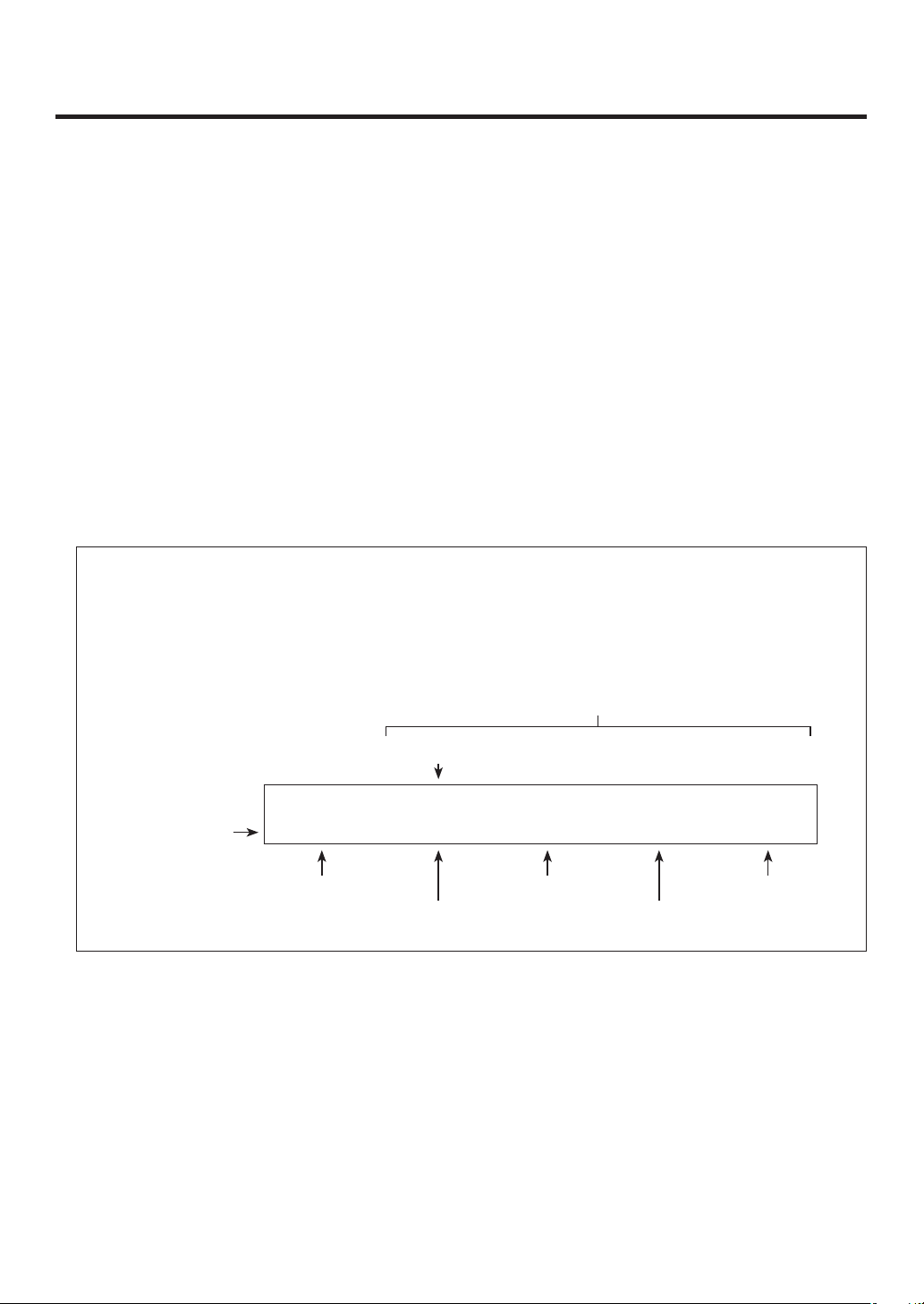
2-1-5. LCD menu area
LCD
The setting menu is displayed when one of the menu function buttons () is pressed.
When the buttons listed below are double-clicked, the specified menu is selected. (The menu delegation
function)
The operation corresponding to the button pressed is also executed.
<List of menu delegation functions>
Button Menu
Transition area BKGD TIME menu/BKGD sub menu
KEY TIME menu/KEY sub menu
WIPE BKGD menu/Border sub menu
Wipe pattern area WIPE #5
(BKGD)
WIPE #5
(KEY)
WIPE #11
(BKGD)
WIPE #11
(KEY)
SQ #5
(BKGD)
SQ #5
(KEY)
SL #5
(KEY)
BKGD menu/WIPEPos sub menu
KEY menu/WIPEPos sub menu
BKGD menu/WIPEPos sub menu
KEY menu/WIPEPos sub menu
BKGD menu/SQPos sub menu
KEY menu/SQPos sub menu
KEY menu/FlyKEY sub menu
25
2. Functions in each area
Menu function buttons [MENU FUNCTION/AUX BUS DELEGATION]
These are used to select the menus organized by function.
Each time one of these buttons is pressed, the menu for its function is switched between the one displayed
above and the one displayed below. Each time the [PinP1/PinP2] button or [DSK1/DSK2] button is pressed, the
color used for their lighting is switched between amber and green. The other buttons light in amber.
Rotary encoders [F1] to [F5]
These are used to set the parameters displayed on the menus (LCD screen or on-screen display).
For details on the operations, refer to the sections in “3. Basic operations”.
[F1]: Rotate this rotary encoder to switch the sub menu.
On the INPUT menu or OUTPUT menu, the signal to be set is switched.
[F2]: Turn this rotary encoder to set the parameters.
On the INPUT menu or OUTPUT menu, the third menu is switched.
[F3] to [F5]: Rotate these rotary encoders to set the parameters.
When the down arrow (↓) is shown at a menu item, its parameter is set by pressing the corresponding rotary
encoder.
When the parameter is one which is set using a numerical value, its default will be restored when the rotary
encoder is held down.
(However, the network settings and the date and time settings will not be returned to the defaults.)
Basic menu operations
For detailed operations, refer to the sections in “3. Basic operations”.
For the menu configurations, refer to “8. Setting menu table”.
Select the menus organized by function using the menu function buttons ().
Using the rotary encoders (), display the sub menu that will be used to establish the detailed settings,
and set the parameters.
Parameter setting area
Third menu
KEY 2|Clip |Gain |Density|Invert
Sub menu
The INPUT menu and OUTPUT menu differ depending on whether an option board has been installed.
[HOLD] button
If the [HOLD] button is pressed while a menu is displayed, no other menu will be selected even when a menu
function button () is pressed.
In addition, even if the AUX bus selection button () is pressed it will not switch to another bus.
While the [HOLD] button is held down, it lights in amber.
Adjust | 0.0| 100.0| 100.0| Off
Operate here
using [F1].
Operate here
using [F2].
Operate here
using [F3].
Operate here
using [F4].
Operate here
using [F5].
26
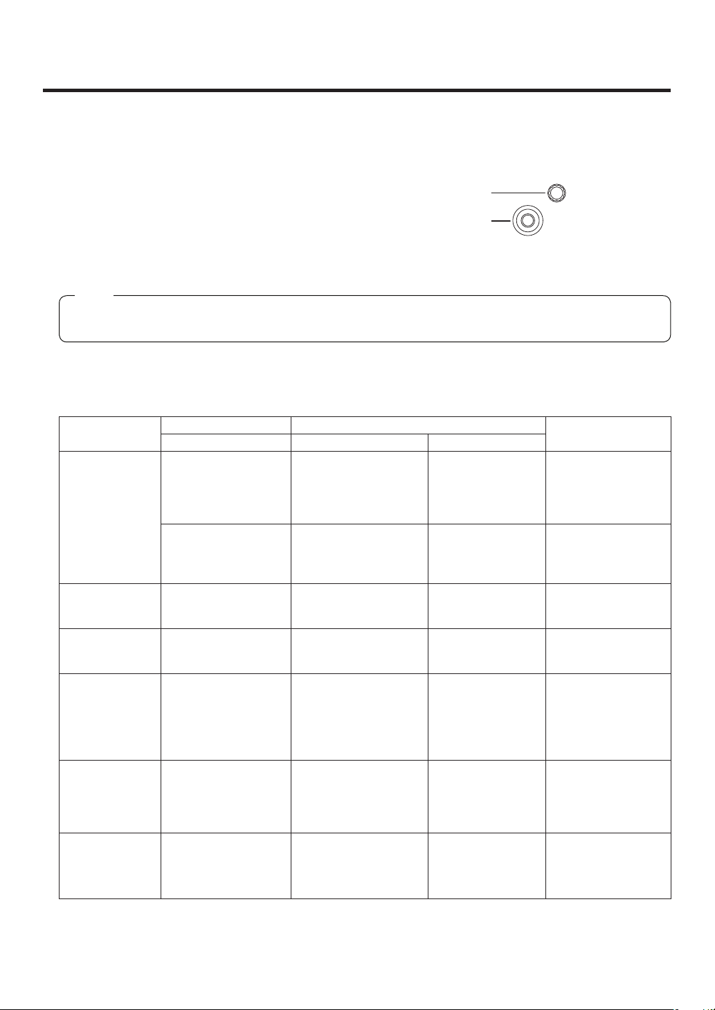
2. Functions in each area
POSITIONER
Z
2-1-6. Positioner area
Positioner [X/Y]
These are used when performing the settings below.
PinP1, PinP2 position settings
Wipe start position setting (WIPE #5, WIPE #11, SQ #5)
Camera control
Flying key position setting
Chroma key marker position setting
In each case, the settings take effect only when the following menu items have been selected.
Note
The center values of the positioner are set during the time it takes for the unit to start up after its power is
turned on. Do not operate the positioner until after the switcher has started up.
Rotary encoder [Z]
This is used to set the PinP size, flying key size or to select the chroma key area.
In each case, the settings take effect only when the following menu items have been selected.
Positioner Rotary encoder
X/Y Z Switch
PinP1, PinP2 Position adjustments Size adjustments
(size increased by rotating
the encoder clockwise
and reduced by rotating it
counterclockwise)
Rotation angle
adjustments
(X-direction and
Y-direction rotation)
WIPE (BKGD) Start position
adjustments
WIPE (KEY) Start position
adjustments
Chroma key Selection position
adjustments
Flying key Position adjustments Size adjustments
Camera control X: Pan control or focus
control
Y: Tilt control or zoom
control
Rotation angle
adjustments
(Z-direction rotation)
— Hold switch down to
— Hold switch down to
Selected area size
adjustments
(size increased by rotating
the encoder clockwise
and reduced by rotating it
counterclockwise)
(size increased by rotating
the encoder clockwise
and reduced by rotating it
counterclockwise)
— Switching between
Hold switch down to
restore initial values
(X/Y, Z).
Hold switch down to
restore initial values
(X/Y, Z).
restore initial values
(X/Y).
restore initial values
(X/Y).
Execute sampling CHR KEY/Sample1
Hold switch down to
restore initial values
(X/Y, Z).
pan/tilt control and
zoom/focus control
Valid menu
All PinP1 and PinP2
menus (except for
PinP1, PinP2/Rotation)
PinP1, PinP2/
Rotation
BKGD/WIPEPos
BKGD/SQPos
KEY/WIPEPos
KEY/SQPos
CHR KEY/Sample2
KEY/FlyKEY
All menus other than
those listed above
27
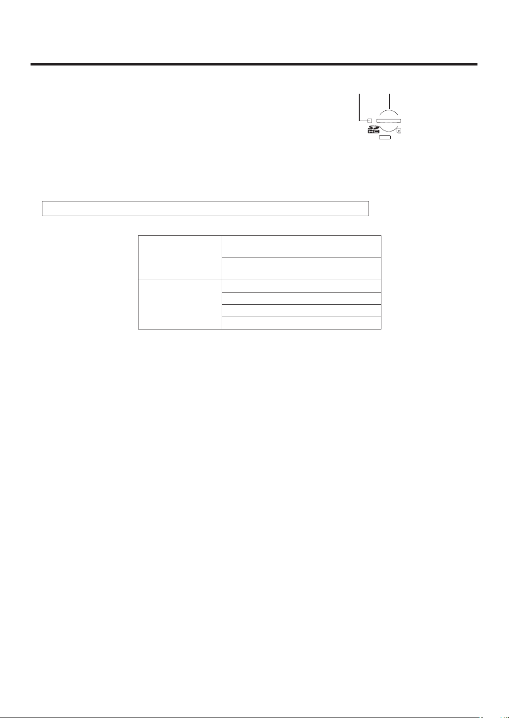
2. Functions in each area
2-1-7. SD memory card area
SD memory card slot
Insert an SD memory card (purchased separately) or an SDHC memory card
(purchased separately) into this slot.
SD memory card access LED
This LED lights while the data on the SD memory card is being accessed.
Do not turn off the unit’s power or eject the SD memory card while the access LED is lighted.
Doing so can damage the data on the SD memory card.
Concerning the recommended SD memory cards and SDHC memory cards
Use of the following SD memory cards and SDHC memory cards made by Panasonic is recommended:
SDHC memory cards RP-SDM04G, RP-SDM06G, RP-SDM08G,
RP-SDM12G, RP-SDM12G
RP-SDV04G, RP-SDV08G, RP-SDV16G,
RP-SDV32G
SD memory cards RP-SD128B, RP-SD256B
RP-SDR512
RP-SDM01G, RP-SDM02G
RP-SDV512, RP-SDV01G, RP-SDV02G
28

2. Functions in each area
2-1-8. Rear panel connections area
NORMAL
SERVICE
TALLY / GPI MAINFRAME
LCD CONTRAST
12V IN 1
SIGNAL
12V IN 2
GND
TALLY/GPI input/output connector [TALLY/GPI] (D-sub 25-pin, female, inch screw)
For details on how to connect this connector, refer to “6. External interfaces”.
MAIN FRAME connector [MAIN FRAME] (RJ-45) (100 Base-TX)
Connect this to the mainframe using the supplied CAT5E cable (STP, straight, 10 m).
DC power input sockets [12V
IN1], [12V IN2] (DC 12 V, 0.8 A)
Connect the supplied AC adapters (for the control panel) to these sockets.
Ground connector [SIGNAL GND]
Connect to the system’s earth ground.
Power switch [POWER]
This is used to turn the power on and off.
SERVICE switch [NORMAL/SERVICE]
This switch is used for maintenance purposes.
For normal operations, select the “NORMAL” position.
LCD CONTRAST adjustment screw
This is used to adjust the contrast of the LCD display.
POWER
OFFON
29
2. Functions in each area
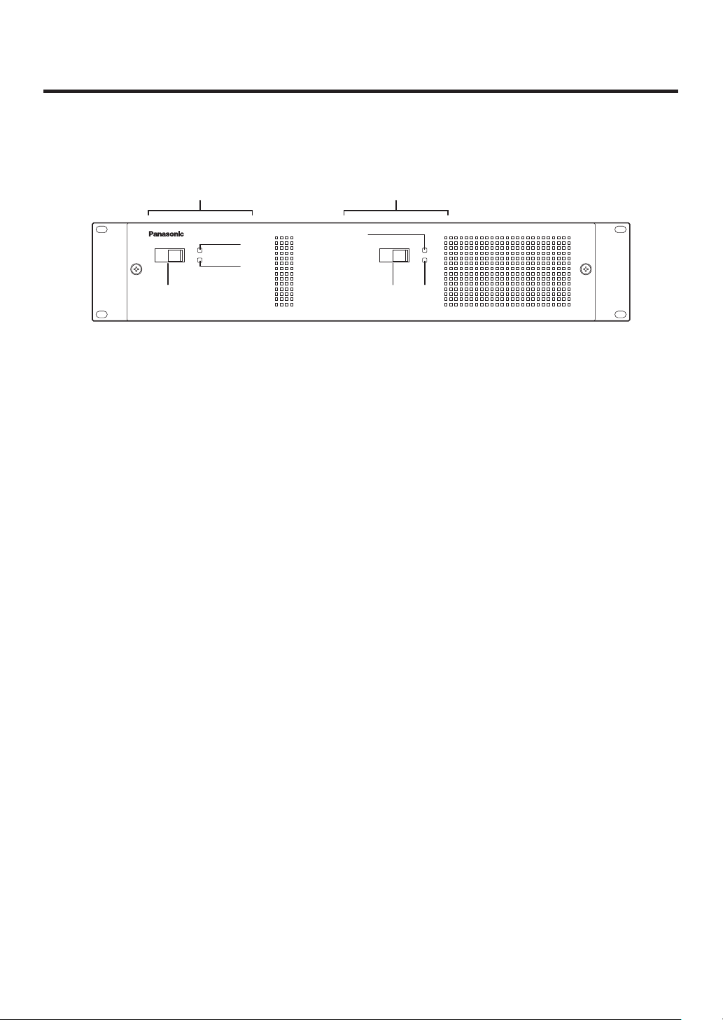
2-2. Mainframe
2-2-1. Front panel
Power supply 1 Power supply 2
POWER1
POWER1
ALARM1
Power switch [POWER1, POWER2]
POWER2
OFF
ONOFF ON
POWER2
ALARM2
Multi-format Live Switcher AV-HS450
These are used to turn the power on and off.
As a standard feature, this mainframe has a redundant power supply system.
To turn off the power, set the power switches of both system 1 (POWER1) and system 2 (POWER2) to OFF.
Power indicator [POWER1, POWER2]
This indicator lights when the power switch () is set to ON while power is supplied to the AC power input
socket.
It goes off when the power switch () is set to OFF.
Alarm indicator [ALARM1, ALARM2]
These light when the mainframe’s cooling fan has stopped running or when there is a problem (voltage drop)
in the power supply. When this occurs, an alarm message is displayed on the control panel’s LCD and on the
OSD screen of the external monitor.
During the occurrence of an alarm, details of the trouble can be checked using the SYSTEM/Alarm menu.
The alarm information can be output to an external device from the TALLY/GPI connector () of the mainframe.
For details, refer to “5-8-2. Alarm message”.
If the alarm goes off, stop using the unit immediately and be sure to contact your dealer.
Continuing to use the unit even after the alarm goes off could damage it.
30
 Loading...