

Panasonic AKW4801C Installation Manual
Cautions for Your Safety
Read the manual carefully before installing, running and maintenance for proper operation.
Before using, master the knowledge of the equipment, safety information and all of other
notes.
This manual uses two safety flags to indicate different levels of danger.
WARNING
●Always take precautions to ensure the overall safety of your system, so that the whole
system remains safe in the event of failure of this product or other external factor.
●Do not use this product in areas with inflammable gas. It could lead to an explosion.
●Exposing this product to excessive heat or open flames could cause damage to the
lithium battery or other electronic parts.
CAUTION
●To prevent abnormal exothermic heat or smoke generation, use this product at the
values less than the maximum of the characteristics and performance that are assured
in these specifications.
● Do not dismantle or remodel the product. It could lead to abnormal exothermic heat or
smoke generation.
●Do not touch the terminal while turning on electricity. It could lead to an electric shock.
●Use the external devices to function the emergency stop and interlock circuit.
●Connect the wires or connectors securely. The loose connection might cause abnormal
exothermic heat or smoke generation.
●Do not allow foreign matters such as liquid, flammable materials, metals to go into the
inside of the product. It might cause exothermic heat or smoke generation.
●Do not undertake construction (such as connection and disconnection) while the power
supply is on.
●Do not use at secondary side circuit of inverter. It might cause exothermic heat or
damage.
A handling error could cause serious physical injury to an operator
and in the worst case could even be fatal.
A handling error could cause serious physical injury to an operator
or damage to the equipment.
Copyright and trademark
● Panasonic Electric Works, Co., Ltd. owns the copyright of this manual.
● We stiffly refuse the reproduction of without permission from this manual.
●Modbus Protocol is a communication protocol that the Modicon Inc. developed for PLC.
●Other company names and the product names are the trademarks or registered
trademarks of each company.

Introduction
Thank you very much indeed for purchasing
“KW2G Eco-POWER METER”.
In this manual, we explain the usage of
“KW2G Eco-POWER METER” in detail.
Please use it correctly after understanding the content
enough.

Table of Contents
Chapter 1 Unit’s Outline ...........................................................................................................................1
1.1 Unit’s Name and Model Numbers............................................................................................................ 1
1.1.1 Main unit......................................................................................................................................... 1
1.1.2 Option............................................................................................................................................. 1
1.2 Measurement items ................................................................................................................................. 2
Chapter 2 Parts Name and Working.........................................................................................................3
2.1 Parts Names............................................................................................................................................ 3
2.2 Key’s Functions........................................................................................................................................ 4
Chapter 3 Installation ...............................................................................................................................5
3.1 Measured-circuit ...................................................................................................................................... 5
3.2 Connection between the main unit and the expansion unit.....................................................................5
3.3 DIN rail mounting..................................................................................................................................... 6
3.4 Terminal arrangement ............................................................................................................................. 7
3.5 Wiring Diagram........................................................................................................................................ 8
3.5.1 In case of using only main unit....................................................................................................... 8
3.5.2 In case of using main unit and connected expansion units.......................................................... 10
3.6 How to attach the Current Transformer (CT).........................................................................................12
3.7 For input connection .............................................................................................................................. 13
3.8 For Output connection........................................................................................................................... 14
3.9 RS485 communication........................................................................................................................... 14
3.10 Low Voltage Directive.......................................................................................................................... 15
Chapter 4 Settings..................................................................................................................................16
4.1 Operation procedure..............................................................................................................................16
4.2 Setting Mode Explanation......................................................................................................................20
4.2.1 MODE 1........................................................................................................................................ 20
4.2.2 Mode 2.......................................................................................................................................... 26
4.2.3 Mode 3.......................................................................................................................................... 27
4.2.4 Mode 4.......................................................................................................................................... 29
Chapter 5 Various Functions..................................................................................................................30
5.1 LOCK mode........................................................................................................................................... 30
5.2 Pulse output function............................................................................................................................. 30
5.2.1 Output depends on integrated electric power.............................................................................. 30
5.2.2 Instantaneous electric power alarm ............................................................................................. 30
5.2.3 Current alarm ............................................................................................................................... 30
5.2.4 Stand-by power alarm.................................................................................................................. 30
5.2.5 Output depends on count value................................................................................................... 30
5.3 Counter function..................................................................................................................................... 31
Chapter 6 Display of each Value............................................................................................................32
6.1 Working of Monitor Display.................................................................................................................... 32
6.2 Display of each measurement value (Common to main unit and expansion unit)................................ 35
6.2.1 Integrated electric power.............................................................................................................. 35
6.2.2 Instantaneous electric power........................................................................................................ 36
6.2.3 Current.......................................................................................................................................... 37
6.2.4 Voltage ......................................................................................................................................... 38
6.2.5 Electricity Charge......................................................................................................................... 39
6.2.6 Carbon dioxide conversion value................................................................................................. 39
6.2.7 Power factor................................................................................................................................. 40
6.2.8 Frequency.....................................................................................................................................40
6.2.9 Counter......................................................................................................................................... 41
6.3 Other indication...................................................................................................................................... 41
6.3.1 Indication while communication ................................................................................................... 41

Chapter 7 Communication......................................................................................................................42
7.1 Communication Procedures .................................................................................................................. 42
7.2 Communication timing ........................................................................................................................... 42
7.3 MEWTOCOL Communication................................................................................................................ 43
7.3.1 Overview of MEWTOCOL-COM (RS485, USB)........................................................................... 43
7.3.2 Data Register List (MEWTOCOL)................................................................................................ 44
7.3.3 Error Codes.................................................................................................................................. 47
7.3.4 Command..................................................................................................................................... 47
7.4 MODBUS (RTU) Communication.......................................................................................................... 49
7.4.1 Overview of MODBUS (RTU)....................................................................................................... 49
7.4.2 Data Register List (MODBUS communication)............................................................................ 52
Chapter 8 How to update the firmware...................................................................................................56
8.1 Prepare Eco-POWER METER to update.............................................................................................. 56
8.2 Update the firmware using KW Version Upgrade Tool.......................................................................... 56
Chapter 9 Specifications.........................................................................................................................61
9.1 Main unit, Expansion unit....................................................................................................................... 61
9.2 Measurement......................................................................................................................................... 62
9.3 Output Specifications............................................................................................................................. 63
9.4 Communication Specifications............................................................................................................... 64
9.5 Applicable standard ............................................................................................................................... 64
9.6 Dedicated Current Transformer Specifications...................................................................................... 65
9.7 Self-diagnostic function.......................................................................................................................... 65
9.8 Power Failure Memory........................................................................................................................... 65
Chapter 10 Mounting..............................................................................................................................66
10.1 Dimensions.......................................................................................................................................... 66
10.1.1 Main unit..................................................................................................................................... 66
10.1.2 Expansion unit............................................................................................................................67
10.1.3 Dedicated CT ............................................................................................................................. 68

Cautions before using
■ Installation environment
◇Do not use the Unit in the following environments.
・Where the unit will be exposed to direct sunlight and where the ambient temperature is outside
the range of -10 to 50 C.
・Where the ambient humidity is outside the range of 30 to 85 % RH (at 20℃, non-condensing)
and where condensation might occur by sudden temperature changes
・Where inflammable or corrosive gas might be produced
・Where the unit will be exposed to excessive airborne dust or metal particles
・Where the unit will be exposed to water, oil or chemicals
・Where organic solvents such as benzene, paint thinner, alcohol, or strong alkaline solutions
such as ammonia or caustic soda might adhere to the product
・Where direct vibration or shock might be transmitted to the product, and where water might wet
the product
・Where the place near high-voltage cable, high-voltage device, power line, power device.
・Where the place near a machinery with transmission function such as amateur radio.
・Where the place near a machinery which occurs the big switching serge
◇Please use the Unit according to the specifications described in this manual. Otherwise, it
may malfunction or cause fire and an electric shock.
・Connect to the power supply in compliance with the rating.
・Refer to the wiring diagram to ensure proper wiring for the power supply, input and output.
・Do not perform wiring or installation with a live line. It may also lead to circuit burnout or fire by
way of the secondary CT side opening.
■ Installation
・Eco-POWER METER is designed to be used in a control panel.
・The power supply terminal and voltage input terminal of the main unit is common. Therefore if
additional noise effects the power supply line, incorrect measurements may result.
・Installation and wiring must be performed by expert personnel for electrical work or electric
piping.
・Do not add an excess power to the display. It might break the inner liquid crystal.
■ As to measurement
・If there is some distortion by harmonic or waveform, it may not measure correctly.
Please check with the actual system before adopts it.
・It might not measure an instantaneous current such as an inrush current or an welding machine.
・When measuring the below loads, it might not satisfy with the accuracy guarantee.
Out of rating current, Load with low power factor,
Load with winding current, Load with ferromagnetic field
・It takes time to update monitor display when many units are connected. However, data update
cycle is not changed.
・The unevenness will be large when using outside of rated frequency.
In this case, set the shift average frequency big.
■ Static electricity
・Discharge static electricity touching the grounded metal etc. when you touch the unit.
・Excessive static electricity might be generated especially in a dry place.
■ Cleaning
・Wipe dirt of the main unit with soft cloth etc. When thinner is used, the unit might deform or be
discolored.

■ Power supply
・Connect a breaker to the voltage input part for safety reasons and to protect the device.
The breaker that connects to the voltage input part must arrange at the position easily reached,
and display shows it is the breaker of the equipment.
・Do not turn on the power supply or input until all wiring is completed.
■ Before power on
Please note the following points when turning on power at the first time.
・Confirm there are neither wiring rubbish nor especially an electrical conduction when installed.
・Confirm neither the power supply wiring, the I/O wiring nor the power-supply voltage are wrong.
・Tighten the installation screw and the terminal screw surely.
・Use an electric wire applicable to the rated current.

KW2G Eco-POWER METER
Chapter 1 Unit’s Outline
KW2G Eco-POWER METER is the wattmeter that can measure electric power, current, voltage, PF and
so on with combination of one main unit and expansion units (power measurement).
By connecting main unit and expansion unit (power measurement), it can measure up to 8-circuit
(16-circuit of single-phase two-wire system).
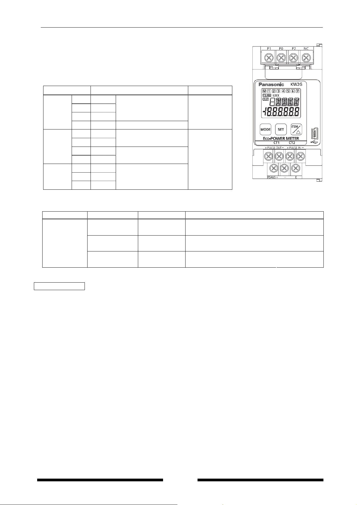
1.1 Unit’s Name and Model Numbers
1.1.1 Main unit
Product name Model No. Connecting method
Main unit AKW2010G
Power supply terminal
(Voltage input terminal)
Pulse I/O terminal
RS485 communication
terminal
Current transformer
(CT)
USB communication Connector
M3.5+ screw
M3+ screw
Connector
Expansion unit
(Power measurement)
AKW2110G
Current transformer
(CT)
*Connect to main unit with the connector.
Connector
1.1.2 Option
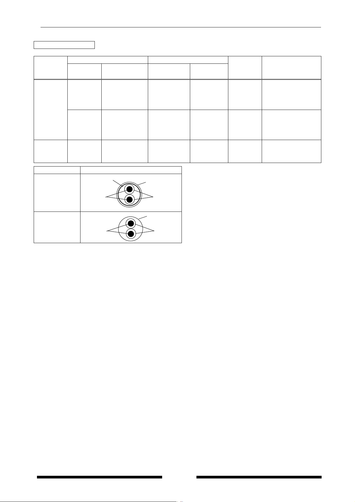
Product name Rated primary current Model No
Dedicated current transformer for 5A/50A 5A / 50A AKW4801C
Dedicated current transformer for 100A 100A AKW4802C
Dedicated current transformer for 250A 250A AKW4803C
Dedicated current transformer for 400A 400A AKW4804C
Product name Model No Remarks
Mounting rail AT8-DLA1 -----
Fastening plate ATA4806 ----Extension cable for CT 1m AKW4701 ----Extension cable for CT 3m AKW4703 ----Extension cable for CT 5m AKW4705 -----
CT trunk cable 1m AKW4811 *1 Required when using 600A CT
1

KW2G Eco-POWER METER
1.2 Measurement items
Item Unit Data range
Integrated electric power (Active) *2
kWh/
MWh
Active *1 kW -9999.99 to 0.000 to 9999.99
Instantaneous
electric power
Reactive *5 kvar -9999.99 to 0.00 to 9999.99
Apparent kVA 0.00 to 9999.99
R-current A 0.000 to 6000.00
Current
N/S-current A 0.000 to 6000.00 (calculated value)
T-current A 0.000 to 6000.00
R(RS)-voltage V 0.0 to 9999.9
Voltage
S(RT)-voltage V 0.0 to 9999.9 (calculated value)
T(TS)-voltage V 0.0 to 9999.9
Electricity charge *3 0.00 to 999999
Conversion value Carbon dioxide kg-CO20.00 to 999999
Power Factor *1
Frequency Hz 47.5 to 63.0
Pulse counter *4 0 to 999999
*1 KW2G can measure regeneration electric power.
While detecting regeneration electric power, minus is displayed on instantaneous active power and
power factor.
*2 Integrated electrical power is not integrated (not subtracted) when detecting regeneration power.
*3 Eco-POWER METER is designed chiefly to manage saving energy.
It is neither intended nor can it be legally used for billing.
*4 Displayed digit of pulse counter differs according to the pre-scale set by pre-scale setting mode.
*5 It determines pulse or minus of instantaneous reactive power by the input measuring voltage and
the input measuring current.
When harmonics or a wave pattern is warped, it may not determine correctly.
(6-digit display) 0.00 to 9999.99MWh
(9-digit display) 0.00 to 9999999.99kWh
-1.00 to 1.00
(without identify leading phase and lagging phase)
2
KW2G Eco-POWER METER
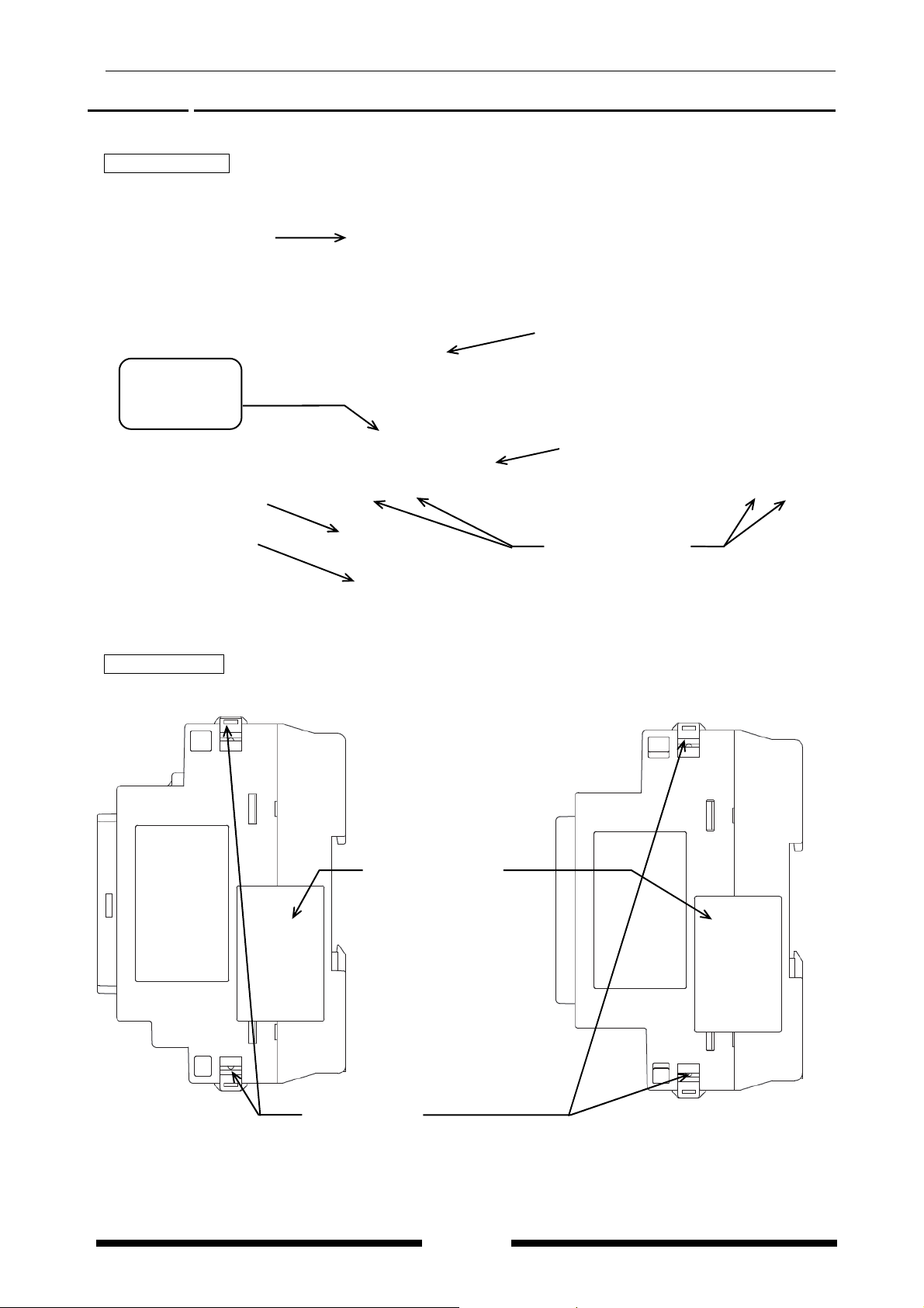
Chapter 2 Parts Name and Working
2.1 Parts Names
Front view
<Main unit> <Expansion unit>
Operating power supply
(Measured voltage input)
(M3.5)
Terminal No.①②③④
Liquid crystal display
MODE key
SET key
ITEM/△ key
Pulse I/O terminal(M3)
Terminal No.⑤⑥⑦⑧
RS485 communication
terminal (M3)
Terminal No.⑨⑩⑪
USB port
Connector for
current transformer(CT)
Side view
<Main unit> <Expansion unit>
Connector label
Peel off before connecting
expansion unit
Do not peel off when not
connecting.
Hook: 2 points
Push the hooks into the unit to fix the expansion unit.
3
KW2G Eco-POWER METER
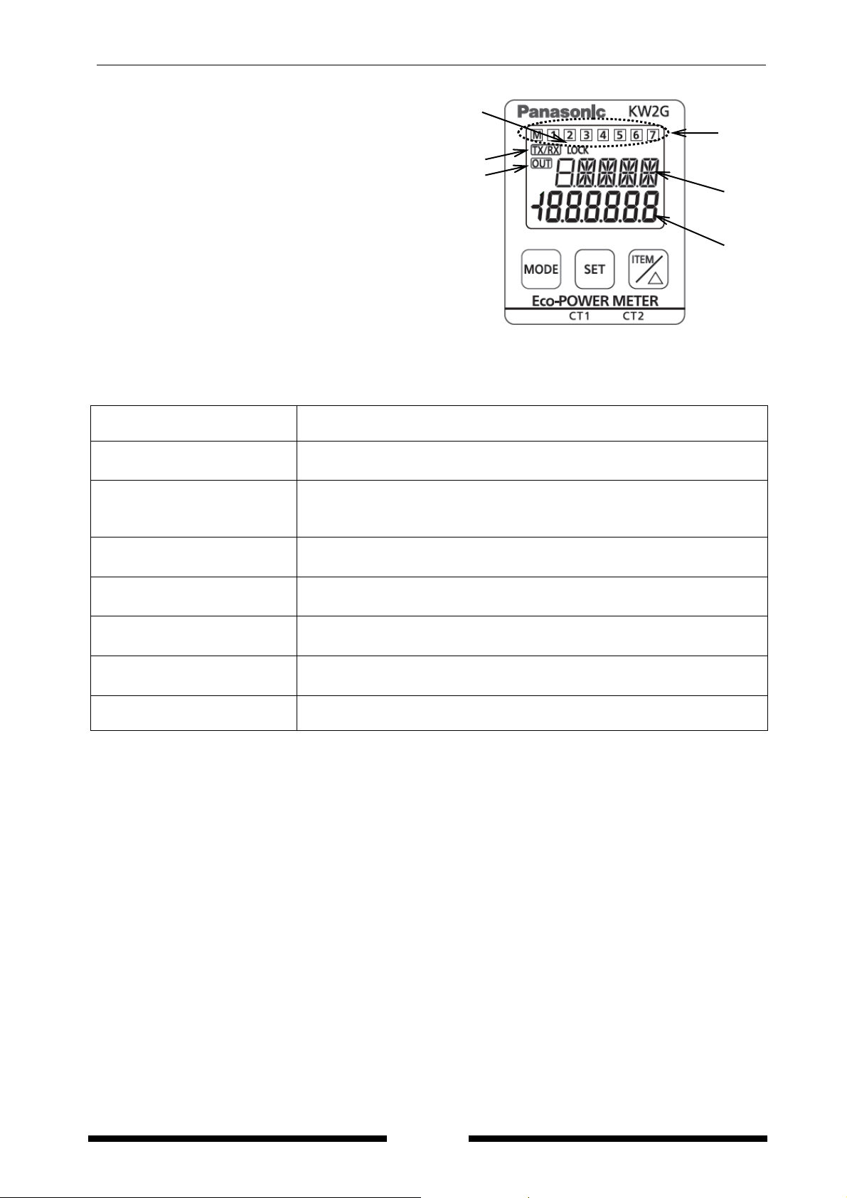
<Display>
①LOCK indicator
Key oper
②
TX/RX indicator
Lighting when communication
ation is invalid while lighting.
①
④
②
③
③OUT indicator
Lighting when pulse output
④Unit number indicator
M: Main unit
1 to 7: Expansion unit
⑤Setting mode indicator
⑥Each measurement value
2.2 Key’s Functions
<MODE>
<MODE>
(continuous press 3-sec)
<SET>
<SET>
(continuous press 3-sec)
<ITEM/△>
<SET> and <ITEM/△>
<ITEM/△>
(continuous press 3-sec)
<SET> and <MODE>
(continuous press 3-sec)
・Shift unit number to display
・Use to shift setting mode
・Use to set each value entered
・Reset stand-by alarm while output the alarm
(only available while output the stand-by alarm)
・All keys locked
・Release lock mode while in lock mode
・To select measured value display
・To select setting value
・To select measured value display
・To select setting value
(While monitoring)
(While setting mode)
(While monitoring)
(While setting mode)
・Shift measured items to display
(Instantaneous electric power, current, voltage)
・To reset the measured value
⑤
⑥
4
KW2G Eco-POWER METER
Chapter 3 Installation
3.1 Measured-circuit
・It is not impossible to use to measure several loads by different strain power supply.
・Each unit can measure 2-circuit of single-phase two-wire system, and 1-circuit of single-phase
three-wire system or three-phase three-wire system.
・It is not impossible to measure by only the expansion unit. Connect expansion units to main unit.
Up to 7 expansion units are connected to 1 main unit.
・Connecting a main unit and expansion units, up to 16-circuit of single-phase two-wire system, up to
8-circuit of single-phase three-wire system or t
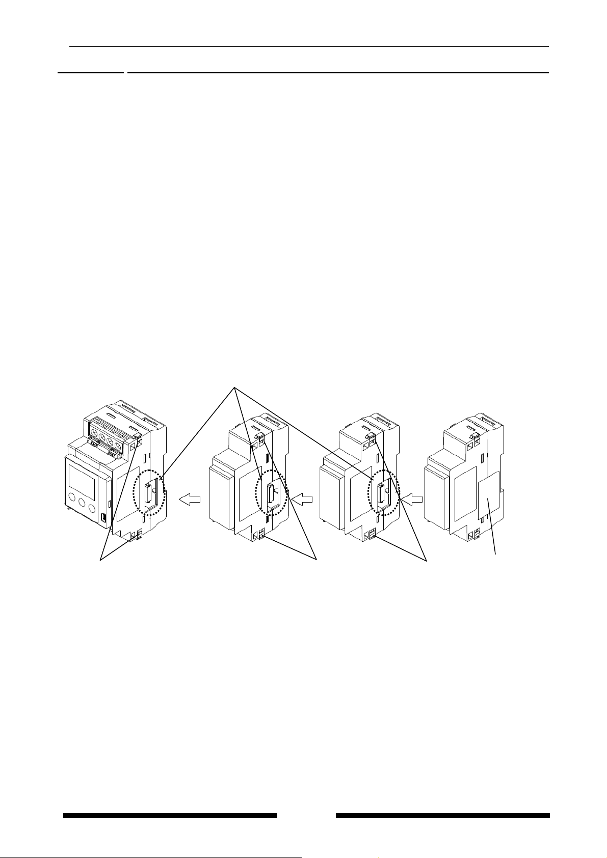
3.2 Connection between the main unit and the expansion unit
・Turn off the power of main unit when connecting expansion units.
・When expanding the units, peel off connector label on the side of each unit and connect male
connector to female connector.
Female connector is on the other side of male connector.
・After connecting, push the hooks into the unit to fix the expansion unit.
・Up to 7 expansion units can be connected per one main unit.
Note) Communication will be stopped or the measurement data will be lost when the units are
removed or connected while turn on power.
Hook Hook Hook Connector label
Expansion connector (male)
hree-phase three-wire system can be measured.
5

KW2G Eco-POWER METER
3.3 DIN rail mounting
Connect all expansion units to the main unit before mounting DIN rail, then mount all connected units
to DIN rail.
Mount
1) Hang the unit on DIN rail.
2) Push it till making click sound and mount.
Note) Check the position of DIN hook (Fig.1) befor
When sever
al expansion units are connected and mounted to DIN rail, moving the hooks
lower (Fig.2) makes mounting easy. After mounting, return to the position of Fig.1.
<Back of main unit> <Back of expansion unit>
Close-up of Close-up of
hook
DIN
Remove
1) Insert minus driver etc. to DIN hook and displace down below.
2) Lift it in the direction of the arrow and remove it.
e mounting.
position DIN hook position
Fig. 1 Fig. 2
6
KW2G Eco-POWER METER
3.4 Terminal arrangement
Be sure to wire correctly according to the terminal arrangement and wiring
diagrams.
After completing wiring, be sure to attach the terminal cover for safety
reasons.
No. Function Screw
Top
Mid
①
②
③
④
⑤ +
⑥ -
⑦ +
⑧ -
P1
P0
P2
Measured voltage input
P1-P0 common to operating
power supply
NC Vacant
Pulse output
Pulse input
M3.5
M3
⑨ +
Bottom
⑩ -
⑪
E
RS485
The input voltage to each terminal is as follows.
Terminal Phase and wire Terminal Input voltage
Measured
voltage input
Single-phase,
two-wire
Single-phase,
three-wire
Three-phase,
three-wire
①-②
(P1-P0)
①-②-③
(P1-P0-P2)
①-②-③
(P1-P0-P2)
100-240VAC (100-240V~)
100-120VAC
(100-120V~:3W)
100-240VAC
(100-240V 3~)
Caution for Wiring
1) Terminal fastening torque should be 0.5 to 0.6N・m for M3 screw and should be 0.8 to 1.0N・m for
M3.5 screw. In case of using a crimping terminal, use it with insulating sleeve applicable to M3 screw
or M3.5 screw.
2) To protect the device, it is necessary to install power switch and circuit breaker in the power supply
circuit. And this has no built-in power switch, circuit breaker or fuse for measured voltage input parts.
Therefore it is necessary to install them in the circuit near this unit.
3) We recommend a wire with the cross section of 0.75 to 1.25mm
2
for power supply line and measured
voltage input line.
4) Use with 10m or less of the input line and 100m or less of the output line.
5) Use flame-resistant cable for each wiring.
<M3.5 screw>
<M3 screw>
① ② ③ ④
⑤ ⑥ ⑦ ⑧
⑨ ⑩ ⑪
(Line voltage)
(Phase voltage)
(Line voltage)
7

KW2G Eco-POWER METER
3.5 Wiring Diagram
3.5.1 In case of using only main unit
Please connect a breaker (3 to 15A) to the power supply (voltage input) part for safety reasons and to
protect the device.
Single-phase two-wire system
◆When measuring a load with rated input voltage
One CT is needed to measure one load.
The below shows that it measures 2-circuit using 2 CTs connected to connectors of unit.
Note)
wiring CT, wire correctly according to this, K for power supply side and L for load side.
(1) Whe
(2) 2 CTs should be same.
◆When measuring a load with exceed input voltage.
Voltage transformer (VT) is needed when you measure a load with over rated input voltage.
Use VT, its secondary side rating is 110V.
Grounding the secondary side of VT and CT is not necessary with low-voltage circuit.
n
Power supply side
2
1
Use P1 and P0 for measuring
1-circuit of 1P2W.
Short P2 and P1 for measuring 2-circuit.
440V 110V
Breaker
VT
P1 P0 P2
8

KW2G Eco-POWER METER
Single-phase three-wire system/Three-phase three-wire system
◆When measuring a load with rated input voltage
Two CTs are needed to measure one load.
Note)
n
(1) Whe
wiring CT, wire correctly according to this, K for power supply side and L for load side.
(2) 2 CTs should be same.
◆When measuring a load with exceed input voltage.
Voltage transformer (VT) is needed when you measure a load with over rated input voltage.
Use VT, its secondary side rating is 110V.
Grounding the secondary side of VT and CT is not necessary with low-voltage circuit.
Power supply side
1 2 3
R N T
R S T
440V
110V
Breaker
VT
P1 P0 P2
9

KW2G Eco-POWER METER
3.5.2 In case of using main unit and connected expansion units
Please connect a breaker (3 to 15A) to the power supply (voltage input) part for safety reasons and to
protect the device.
Single-phase two-wire system
◆When measuring a load with rated input voltage
Note)
wiring CT, wire correctly according to this, K for power supply side and L for load side.
(1) Whe
n
(2) Using all CTs for one unit should be same.
◆When measuring a load with exceed input voltage.
Voltage transformer (VT) is needed when you measure a load with over rated input voltage.
Use VT, its secondary side rating is 110V.
(Refer to the previous 3.6.1 in detail.)
10

KW2G Eco-POWER METER
Single-phase three-wire system/Three-phase three-wire system
◆When measuring a load with rated input voltage
Note)
(1) When
wiring CT, wire correctly according to this, K for power supply side and L for load side.
(2) Using all CTs for one unit should be same.
◆When measuring a load with exceed input voltage.
Voltage transformer (VT) is needed when you measure a load with over rated input voltage.
Use VT, its secondary side rating is 110V.
(Refer to the previous 3.6.1 in detail.)
11

KW2G Eco-POWER METER
A
3.6 How to attach the Current Transformer (CT)
・One CT is needed for 1 unit when measuring 1P2W (2 CTs for 2-circuit). Two CTs are needed when
measuring 1P3W/3P3W. Using all CTs for one unit should be the same.
・Check beforehand that the thickness of the electric wire is smaller than the through-hole of the CT.
・When connecting CT, connect the secondary side to the terminal of the main unit first, and after that
wire the primary side to a load electric wire. Incorrect order might cause an electric shock or break CT.
・The CT has polarity. Wire correctly according to the K and L marks. Wrong direction can’t measure
correctly.
・When closing CT, check that there is no foreign materials on the divided face. And make sure it is
closed securely once the wire is in place; if not the measurement value will be not accurate.
・When CT’s cable is extended, it is possible to extend up to about 10m with the cable of AWG#22 or
more cross section under the environment without noise at all. Please use the thick cable as much as
possible.
◆To connect CT with secondary side current 5A
How to connect for measuring by combination with CT (secondary side current 5A)
(1) Select 5A at CT type setting mode (CT-T).
(2) Set the primary current of measured CT (secondary side current 5A) at primary side current of
CT setting mode (CT-1).
< ex > If the measured CT is 400A/5A, set to”400”.
(3) Clamp the dedicated CT for 5A (AKW4801C), which is connected to the main unit first, to
secondary side of the CT (secondary side current 5A). CT direction (K→L) should be set for the
commercial CT direction.
*Set the CT (secondary side current 5A) and the AKW4801C approximately 1m apart. If the two
CTs are set too close each other, it may not measure accurately due to magnetic field
interference.
(Connection example)
With Ammeter etc.
Power supply
Breaker
K
L
Load
Secondary current
CT with 2nd current 5A
mmeter etc.
L K
Dedicated CT (For 5A)
AKW4801C
Eco-POWER
METER
12
KW2G Eco-POWER METER
r
Without Ammeter
Power supply
Breaker
Secondary current
K
CT with 2nd current 5A
L
Load
Shorted or resistor less than 0.1Ω
L K
Eco-POWER
Dedicated CT (For 5A)
AKW4801C
METER
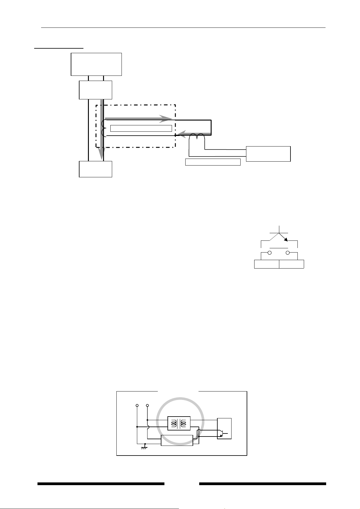
3.7 For input connection
・Contact input
Use highly reliable metal plated contacts. Since the contact’s
bounce time leads directly to error in the count value, use
contacts with as short a bounce time as possible. In general,
select 30Hz for max. counting speed.
・Non-contact input (Transistor input)
ect with an open
Conn
following specifications. V
collector. Use the transistor with the
=20V min. IC=20mA min. I
CEO
CBO
=6μA
PULSE
⑦ ⑧
IN +
PULSE
IN -
max
Use transistors with a residual voltag
e of less than 2V when the transistor is ON.
*Short-circuit impedance should be less than 1kΩ.
(When the impedance is 0Ω, drain current is approx. 7mA.)
Open-circuit impedance should be more than 100kΩ.
・Input wiring
Please wire up to 10m by using a shielded wire or a metallic electric wire tube individually.
(Note)
Operating power supply input part and measured voltage input are not insulated to pulse input parts.
So the input equipment must have the power supply transformer in which the secondary side is not
grounded with the primary and secondary sides insulated, in order to prevent interference of the
power supply circuit when connecting the external input circuit. Be sure not to use an
auto-transformer.
AC power supply
(Fig. A)
Good example
Insulated
transforme
(-)
(+)
Input equipment
(sensor etc.)
Eco-POWER
METER
13
KW2G Eco-POWER METER
r
A
r
y
A
y
(Fig.B) No Good example
AC power suppl
Insulated
transforme
Eco-POWER
METER
Do not ground the secondary side.
(+)
(-)
Input equipment
(sensor etc.)
C power suppl
uto transforme
Eco-POWER
METER
Do not use an auto-transformer.
(+)
(-)
Input equipment
(sensor etc.)
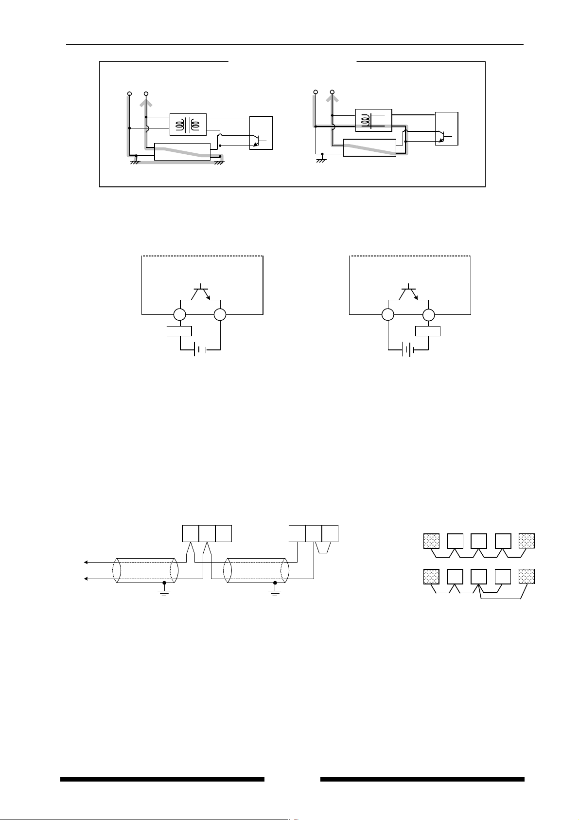
3.8 For Output connection
・Since the transistor output is insulated from the internal circuit by a photo-coupler, it can be used both
as a NPN output and PNP (equal value) output.
Eco-POWER METER
Eco-POWER METER
NPN output
Pulse (+) PNP output
5
Load
Pulse (-)
6
- +
Power supply for Load
Pulse (+)
5
Power supply for Load
Pulse (-)
6
Load
- +
・Wire up to 100m for output connection.
3.9 RS485 communication
・When using shielded cable for the RS485 transmission line, ground one end.
Use a class D dedicated earth for grounding. Do not share a ground with other earth lines. (Fig.1)
・Be sure to connect with daisy chain the RS485 transmission line between each unit.
Do not use a splitter. (Fig.2)
・With a terminal station, RS485 (E) and RS485 (-) should be shorted.
(Fig.1) (Fig.2)
To RS-485
device
Shielded cable Shielded cable
Eco-POWER MET R E
General station
(+) (+)
Class D grounding Class D grounding
(-) (E)(-)
( E )
Eco-POWER MET RE
Terminal station
Shorted
Correct wiring
○
Incorrect wiring
×
Terminal Terminal
st
ation station
14
KW2G Eco-POWER METER
Recommended Cable
Use the transmission cables shown below for Eco-POWER METER RS485 communication system.
Conductor Insulator
Cable
Twisted-
Size
1.25 mm
(AWG16)
or more
Resistance
(at 20℃)
2
Max.16.8Ω/km
Material Thickness
Polyethylene
pair
with shield
0.5 mm
(AWG20)
2
Max.33.4Ω/km
Polyethylene
or more
2
Max.25.1Ω/km
PVC
VCTF
0.75 mm
(AWG18)
or more
Cable Section
Twisted-pair
with shield
Shield
Conductor Insulator
Jacket
Max.
0.5 mm
Max.
0.5 mm
Max.
0.6 mm
Notes
1) Use shielded type twist cables.
2) Use only one type of the transmission cables.
2) Do not mix different types of the cables.
3) Use twist pair cables under a bad noise
environment.
Cable
diameter
Approx.
8.5 mm
Approx.
7.8 mm
Approx.
6.6 mm
Applicable cable
HITACHI
KPEV-S
1.25 mm
2
×1P
Belden Inc. 9860
HITACHI
KPEV-S
0.5 mm
2
×1P
Belden Inc. 9207
VCTF
0.75 mm
2
×2C
(JIS)
Jacket
VCTF
Conductor Insulator
3.10 Low Voltage Directive
When using in the application conforming to EN61010-1/IEC61010-1, make sure to satisfy the following
conditions.
(1) Pulse output part and communication part secure only basic insulation. In order to secure reinforced
(double) insulation demanded by EN 61010-1/ IEC61010-1, secure basic insulation or more with
load side for output part and secure basic insulation or more with communication system side for
communication part.
(2) Provide the voltage input part with an EN60947-1 or EN60947-3 compliant circuit breaker.
The breaker that connects to the voltage input part must arrange at the position easily reached,
and display shows it is the breaker of the equipment.
(3) Use a wire with basic insulation or more for a wire cramped (or connected) CT.
【Environmental conditions】
・Overvoltage category Ⅱ, Pollution degree 2
・Indoor use
・An ambient temperature of –10 to 50℃
・An ambient non-condensing humidity of 35 to 85%RH (at 20℃)
・Altitude of 2000m or less
【Mount the product in a place with】
・A minimum of dust, and an absence of corrosive gases
・No flammable, explosive gasses
・Few mechanical vibrations or shocks
・No exposure to direct sunlight
・No large capacity electromagnetic switches or cables through which large current is flowing
15
KW2G Eco-POWER METER
Chapter 4 Settings
4.1 Operation procedure
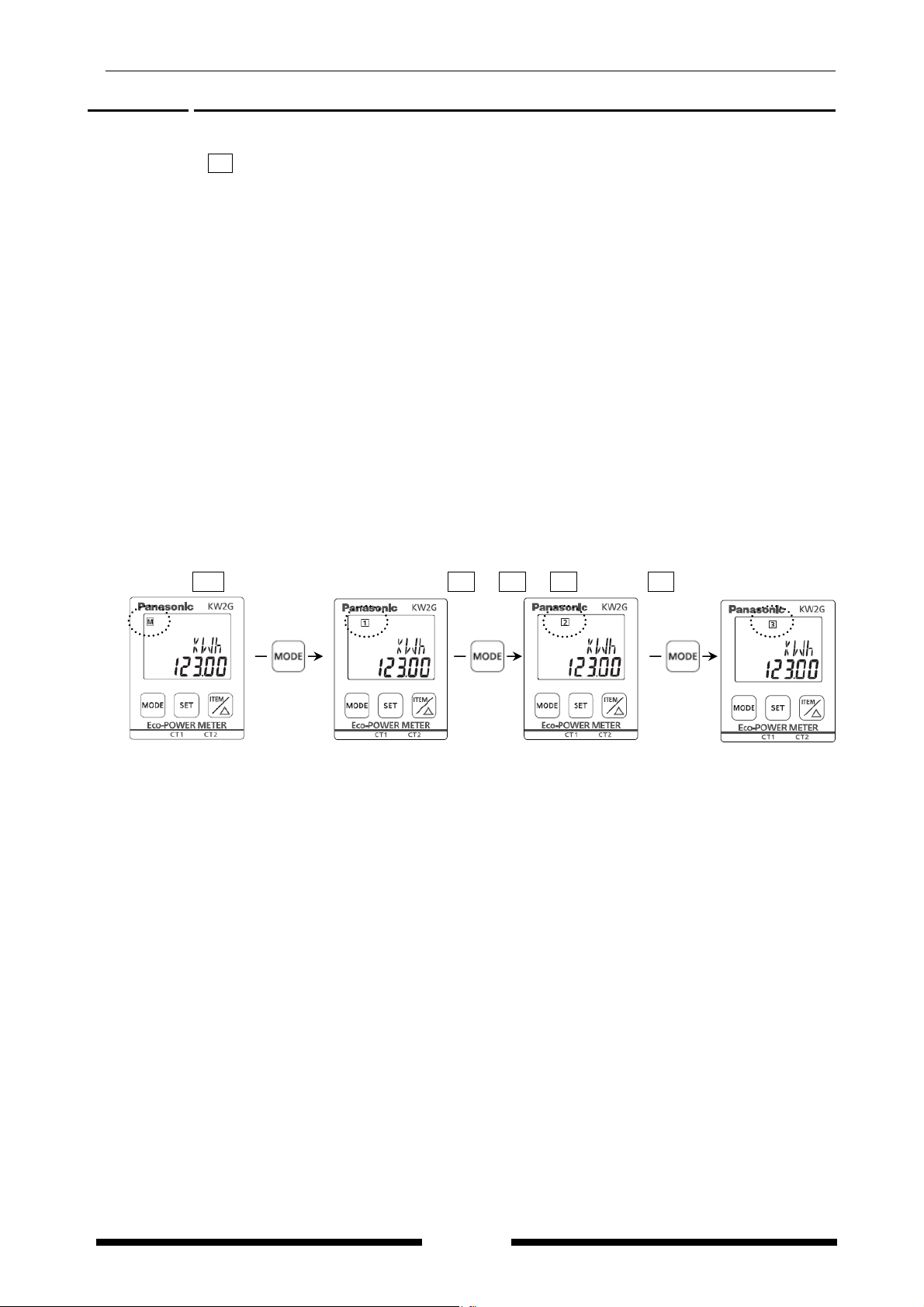
When power on, M and connected expansion unit number turn on the display of main unit. After that, it
displays the monitor display (measuring value).
【Basic setting to measure】
When wiring Eco-POWER METER and CT and setting mode 1 after power on, Eco-POWER Meter can
measure the electric power. In order to use the other functions, set mode2, 3 and 4 according to your
use.
Mode 1: Mode for setting about power measurement
Mode 2: Mode for setting about pulse measurement
Mode 3: Mode for setting about serial communication (RS485)
Mode 4: Mode for setting about optional function
In addition, when connecting main unit and expansion units, there are some items that are necessary to
set each unit.
【Unit change】
Before setting, press <MODE> to shift display of main unit (M) and expansion units (1 to 7) to set.
Settings about functions of pulse output, alarm output and communication on main unit can be set even
if it changes to an expansion unit.
Main unit M Lighting
Expansion unit 1 2 3 to 7 Lighting
16

KW2G Eco-POWER METER
Mode 1…Mode for setting each parameter for power measurement
The mode with (※) mark can be set to each unit.
Monitor (Display when power on)
(Mode 1)
<MODE> continuous
Setting mode
(Mode 2) (Mode 3) (Mode 4)
<SET>
Phase/Wire system setting mode (※)
SYST
CT type setting mode (※)
<SET>
CT-T
VT setting mode
When select
other than “5A”
<SET>
VT
Shift average frequency
setting mode (※)
<SET>
When select
<SET> <SET> <SET>
“5A”
<SET>
<SET>
AVG
Simple measuring setting mode
<SET>
SIMP
Cutoff current setting mode (※)
When select
“OFF”
<SET>
CUTA
Unit for pulse output setting mode
<SET>
When select
“ON”
<SET>
Simple voltage setting mode
<SET>
PL-P
When select
“Values”
<SET>
When select “AL-P”
<SET>
Power alarm setting
mode
AL-P
<SET> <SET>
Electricity rate setting mode
When select “AL-C”
Current alarm setting
mode
AL-C
<SET>
RATE
Conversion factor setting mode
<SET>
CO2
<SET>
Monitor
Press <MODE> to return Monitor.
Refer to the next page.
Primary side current of
CT setting mode (※)
CT-1
S.VLT
<SET>
Simple PF setting mode
S.PF
When select “AL-S”
<SET>
Stand-by alarm setting
mode 1
AL-S 1
<SET>
Stand-by alarm setting
mode 2
AL-S 2
<SET>
When select “Cnt”
Preset value setting
mode
Cnt
<SET>
<SET>
17
 Loading...