

Panasonic AJ-YA120AG User Manual
Digital HD Video Cassette Player/Recorder
The unit’s recording function become operational only when
the AJ-YA120AG (optional accessory) or AJ-YAD120AG
(optional accessory) has been installed.
VQT0L37-1
Before operating this product, please read the instructions carefully and save this manual for future use.
Operating Instructions
Model No. AJ- E
2
$
THIS APPARATUS MUST BE EARTHED
To ensure safe operation the three-pin plug must be
inserted only into a standard three-pin power point
which is effectively earthed through the normal
house-hold wiring.
Extension cords used with the equipment must be
three-core and be correctly wired to provide
connection to earth. Wrongly wired extension cords
are a major cause of fatalities.
The fact that the equipment operates satisfactorily
does not imply that the power point is earthed and
that the installation is completely safe. For your
safety, if in any doubt about the effective earthing of
the power point, consult a qualified electrician.
$
DO NOT REMOVE PANEL COVER BY
UNSCREWING.
To reduce the risk of electric shock, do not remove
cover. No user serviceable parts inside.
Refer servicing to qualified service personnel.
CAUTION:
TO REDUCE THE RISK OF FIRE OR SHOCK
HAZARD AND ANNOYING INTERFERENCE, USE
THE RECOMMENDED ACCESSORIES ONLY.
CAUTION:
TO REDUCE THE RISK OF FIRE OR SHOCK
HAZARD, REFER MOUNTING OF THE OPTIONAL
INTERFACE BOARD TO QUALIFIED SERVICE
PERSONNEL.
CAUTION:
Do not install or place this unit in a bookcase,
built-in cabinet or any other confined space in
order to maintain adequate ventilation. Ensure
that curtains and any other materials do not
obstruct the ventilation to prevent risk of electric
shock or fire hazard due to overheating.
CAUTION:
TO REDUCE THE RISK OF FIRE OR SHOCK
HAZARD, REFER CHANGE OF SWITCH SETTING
INSIDE THE UNIT TO QUALIFIED SERVICE
PERSONNEL.
WARNING:
OTO REDUCE THE RISK OF FIRE OR SHOCK
HAZARD, DO NOT EXPOSE THIS EQUIPMENT
TO RAIN OR MOISTURE.
OTO REDUCE THE RISK OF FIRE OR SHOCK
HAZARD, KEEP THIS EQUIPMENT AWAY FROM
ALL LIQUIDS-USE AND STORE ONLY IN
LOCATIONS WHICH ARE NOT EXPOSED TO
THE RISK OF DRIPPING OR SPLASHING
LIQUIDS, AND DO NOT PLACE ANY LIQUID
CONTAINERS ON TOP OF THE EQUIPMENT.
CAUTION:
THE AC OUTLET (MAINS SOCKET) SHALL BE
INSTALLED NEAR THE EQUIPMENT AND SHALL
BE EASILY ACCESSIBLE.
CAUTION:
Even when the Power Switch is in the OFF
position, a small current flows the filter circuit.
indicates safety information.
For your safety
IMPORTANT
“Unauthorized recording of copyrighted
television programmes, video tapes and other
materials may infringe the right of copyright
owners and be contrary to copyright laws.”
Operating precaution
Operation near any appliance which generates
strong magnetic fields may give rise to noise in the
video and audio signals. If this should be the case,
deal with the situation by, for instance, moving the
source of the magnetic fields away from the unit
before operation.
3
FOR U.K. ONLY
This appliance is supplied with a moulded three pin
mains plug for your safety and convenience.
A 13 amp fuse is fitted in this plug.
Should the fuse need to be replaced please ensure that
the replacement fuse has a rating of 13 amps and that it
is approved by ASTA or BSI to BS1362.
Check for the ASTA mark Ïor the BSI mark Ìon the
body of the fuse.
If the plug contains a removable fuse cover you must
ensure that it is refitted when the fuse is replaced.
If you lose the fuse cover the plug must not be used
until a replacement cover is obtained.
A replacement fuse cover can be purchased from your
local Panasonic Dealer.
IF THE FITTED MOULDED PLUG IS UNSUITABLE
FOR THE SOCKET OUTLET IN YOUR HOME THEN
THE FUSE SHOULD BE REMOVED AND THE PLUG
CUT OFF AND DISPOSED OF SAFELY. THERE IS A
DANGER OF SEVERE ELECTRICAL SHOCK IF THE
CUT OFF PLUG IS INSERTED INTO ANY 13 AMP
SOCKET.
If a new plug is to be fitted please observe the wiring
code as shown below.
If in any doubt please consult a qualified electrician.
WARNING: THIS APPLIANCE MUST BE EARTHED.
IMPORTANT: The wires in this mains lead are coloured
in accordance with the following code:
Green-and-Yellow: Earth
Blue: Neutral
Brown: Live
Caution for AC Mains Lead
As the colours of the wires in the mains lead of this
appliance may not correspond with the coloured
markings identifying the terminals in your plug, proceed
as follows:
• The wire which is coloured GREEN-AND-YELLOW
must be connected to the terminal in the plug which is
marked with the letter E or by the Earth symbol Óor
coloured GREEN or GREEN-AND-YELLOW.
• The wire which is coloured BLUE must be connected
to the terminal in the plug which is marked with the
letter N or coloured BLACK.
• The wire which is coloured BROWN must be
connected to the terminal in the plug which is marked
with the letter L or coloured RED.
FOR YOUR SAFETY PLEASE READ THE FOLLOWING TEXT CAREFULLY.
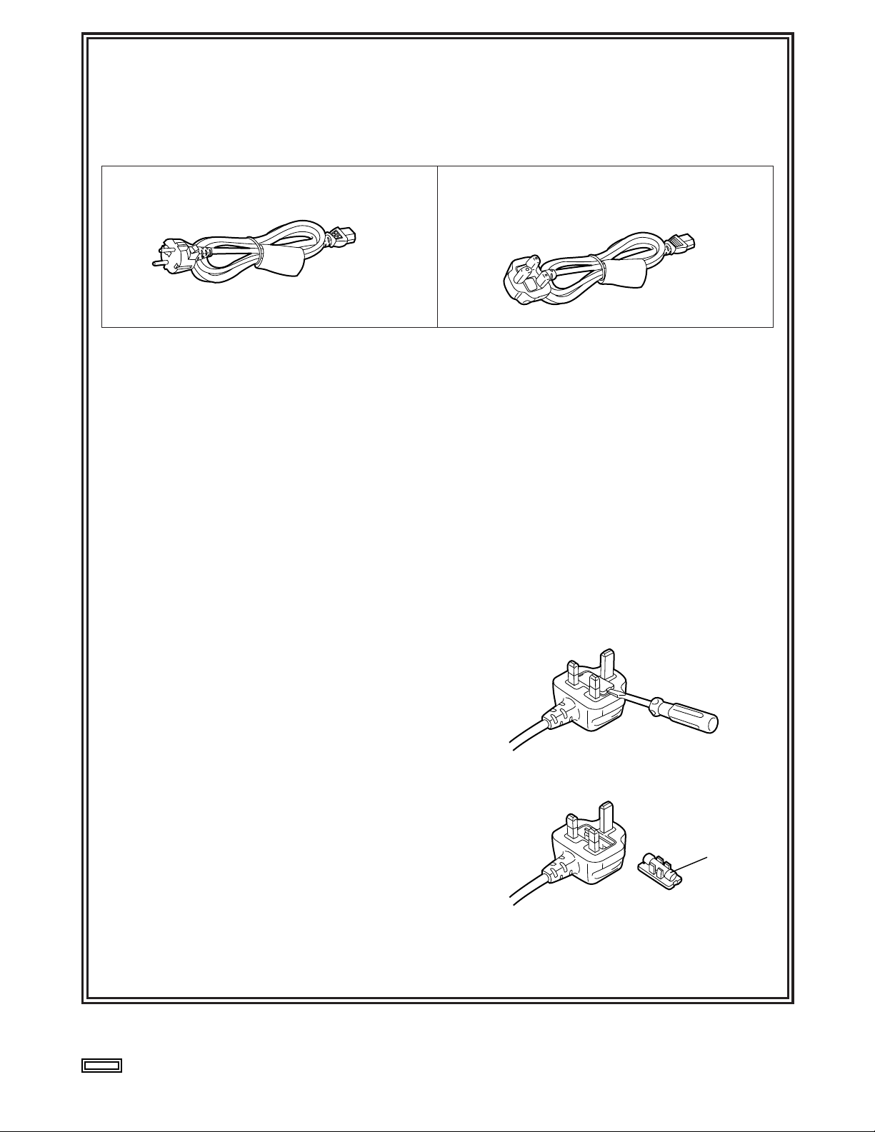
This product is equipped with 2 types of AC mains cable. One is for continental Europe, etc. and the other one is only
for U.K.
Appropriate mains cable must be used in each local area, since the other type of mains cable is not suitable.
FOR CONTINENTAL EUROPE, ETC.
Not to be used in the U.K.
FOR U.K. ONLY
If the plug supplied is not suitable for your socket
outlet, it should be cut off and appropriate one fitted.
How to replace the fuse
1.Open the fuse compartment with a screwdriver.
2.Replace the fuse.
Fuse
indicates safety information.

4
Contents
Introduction . . . . . . . . . . . . . . . . . . . . . . . 5
Features . . . . . . . . . . . . . . . . . . . . . . . . . . .5
Parts and their functions . . . . . . . . . . . . . 7
Front panel . . . . . . . . . . . . . . . . . . . . . . . . . . . . . . 7
Rear panel . . . . . . . . . . . . . . . . . . . . . . . . . . . . . . 12
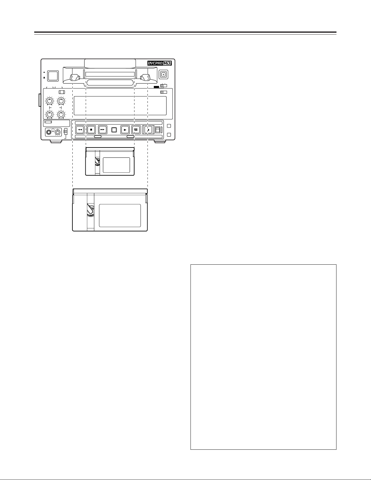
Tapes . . . . . . . . . . . . . . . . . . . . . . . . . . . .14
Inserting the tape . . . . . . . . . . . . . . . . . . . . . . . . .14
Usable tapes . . . . . . . . . . . . . . . . . . . . . . . . . . . .14
Operation . . . . . . . . . . . . . . . . . . . . . . . . .15
Turning on the unit’s power . . . . . . . . . . . . . . . . . 15
STOP mode . . . . . . . . . . . . . . . . . . . . . . . . . . . . 15
Recording . . . . . . . . . . . . . . . . . . . . . . . . . . . . . . 16
Pause/recording (follow-on recording) . . . . . . . . 16
Playback . . . . . . . . . . . . . . . . . . . . . . . . . . . . . . . 17
Cue/review . . . . . . . . . . . . . . . . . . . . . . . . . . . . . 17
Still image playback . . . . . . . . . . . . . . . . . . . . . . 17
Linear 0.3k playback . . . . . . . . . . . . . . . . . . . . . 18
Variable speed playback . . . . . . . . . . . . . . . . . . . 18
Repeat playback . . . . . . . . . . . . . . . . . . . . . . . . . 19
Time code & user’s bit . . . . . . . . . . . . . .20
Time code . . . . . . . . . . . . . . . . . . . . . . . . . . . . . . 20
User’s bit . . . . . . . . . . . . . . . . . . . . . . . . . . . . . . . 20
Setting the time code (from the menu) . . . . . . . . 20
Setting the time code (from the front panel) . . . . 20
Setting the user’s bit . . . . . . . . . . . . . . . . . . . . . . 21
Playing back the time code and user’s bit . . . . . . 21
Superimposed screen displays . . . . . . 22
Setup (initial settings) . . . . . . . . . . . . . . .24
Setting method using the on-screen menus . . . . 24
Returning to the factory settings . . . . . . . . . . . . . 24
Setting the user defaults . . . . . . . . . . . . . . . . . . . 25
Loading the user defaults . . . . . . . . . . . . . . . . . . 26
Menu protection . . . . . . . . . . . . . . . . . . . . . . . . . 26
Releasing the menu protection mode . . . . . . . . . 27
Displaying the DIAG menu . . . . . . . . . . . . . . . . . 27
Setup menus . . . . . . . . . . . . . . . . . . . . . .28
Menus which are displayed . . . . . . . . . . . . . . . . . 28
SYSTEM . . . . . . . . . . . . . . . . . . . . . . . . . . . . . . . 31
BASIC . . . . . . . . . . . . . . . . . . . . . . . . . . . . . . . . . 33
OPERATION . . . . . . . . . . . . . . . . . . . . . . . . . . . . 37
INTERFACE . . . . . . . . . . . . . . . . . . . . . . . . . . . . 40
TAPE PROTECT . . . . . . . . . . . . . . . . . . . . . . . . . 40
TIME CODE . . . . . . . . . . . . . . . . . . . . . . . . . . . . 41
VIDEO . . . . . . . . . . . . . . . . . . . . . . . . . . . . . . . . . 43
AUDIO . . . . . . . . . . . . . . . . . . . . . . . . . . . . . . . . . 45
MENU . . . . . . . . . . . . . . . . . . . . . . . . . . . . . . . . . 47
DIF . . . . . . . . . . . . . . . . . . . . . . . . . . . . . . . . . . . 48
Error messages . . . . . . . . . . . . . . . . . . . .49
Condensation . . . . . . . . . . . . . . . . . . . . .51
Emergency eject . . . . . . . . . . . . . . . . . . . 52
Video head cleaning . . . . . . . . . . . . . . . .52
Maintenance . . . . . . . . . . . . . . . . . . . . . . .52
Specifications . . . . . . . . . . . . . . . . . . . . .53

5
Introduction
The AJ-HD1200A multi-format digital video cassette
player is capable of playing not only all types of
materials ranging from HD (DVCPRO HD and
DVCPRO HD-LP) to SD (DVCPRO50, DVCPRO50P
and DVCPRO) recorded in the DVCPRO formats on
1/4-inch wide compact cassette tapes but also
consumer DV and DVCAM tapes.
A down-converter provided as a standard feature
verifies all tapes, whatever their format, using analog
composite output signals.
Furthermore, by installing an optional board, the unit
can be used as a recorder to record HD signals
(1080i/59.94 Hz, 1080i/50 Hz or 720p/59.94 Hz) in the
DVCPRO HD-LP format. In addition, 720/24p over
60p sources recorded using a variable frame rate
camera can be converted into 1080/24 PsF format
output signals to support cinema applications.
Similarly, 720/25p over 60p sources can be converted
into 1080/25 PsF or 576i format output signals.
Thanks to the incorporation of highly efficient digital
compression technology, the deteriorations in the
image and sound quality during dubbing are now
significantly reduced with this high image quality VTR.
The compact size and light weight of the unit enable it
to be carried around and mounted in a standard rack
with ease.
You can perform the unit’s settings interactively with
the on-screen menus displayed on the TV monitor.
Features
Compact size and light weight.
The unit has a width of 214 mm, a height of 132
mm, and a depth of 428 mm, and weighs only 7.9
kg.
Grips are also attached for easy carry.
Efficient installation in a rack
The unit’s width is one-half of 19 inches and its
height is 3U: this translates into greater saving of
installation space in a standard rack compared to
conventional models.
DVCPRO HD cassette tapes used
The unit uses 1/4-inch wide cassette tapes.
<Note>
When recording2HD signals, use DVCPRO HD
cassettes.
High image quality
The unit achieves a high image quality by recording
4:2:2 HD component signals with a recording rate
(=100 Mbps) which is four times as high as that for
existing DVCPRO formats.
1080i or 720p, NTSC or PAL selectable
By switching the settings provided for the video
signal input (1080i/59.94 Hz or 720p/59.94 Hz) on
the setup menu, the unit can record2and play back
the signals of the system selected.
The unit also supports the PAL mode. Playback of
1080i/50 Hz or PAL SD materials is enabled by
switching the setting on the system menu.
Frame rate conversion
When playing back a tape recorded at a frame rate
of 24 fps using a variable frame rate camera, the
tape’s signals can be converted to the 1080/24 PsF
format and output by selecting a menu item setting.
When playing back a tape recorded at a frame rate
of 25 fps, the tape’s signals can be converted to the
1080/25 PsF or 576i format and output.
<Notes>
O Use tapes that are shot with a variable frame
rate camera.
O Do not use dubbed or edited tapes. The tape
control information may be lost, making it
impossible to convert the signals for playback.
O To convert a tape recorded using a frame rate
other than 24 (25) fps to the 1080/24 (25) PsF
format, use the frame rate converter (AJ-FRC27)
available as an optional accessory.
DVCPRO-compatible playback
In addition to DVCPRO HD-LP playback, the unit
can play back tapes recorded using the existing
DVCPRO HD, DVCPRO50 and DVCPRO formats.
It can also play back consumer DV tapes (SP) and
DVCAM tapes.
2 The unit’s recording function become operational
only when the AJ-YA120AG (optional accessory)
or AJ-YAD120AG (optional accessory) has been
installed.

6
<Playback formats and output formats>
Playback format Output format
DVCPRO HD-LP,
DVCPRO HD
DVCPRO HD,
DVCPRO50, DV
DVCPRO P, DV, DVCAM DV
When the E-E mode is
established:
O Install the AJ-YA120AG board
which is available as an optional
accessory.
O Select a setting other than
“1394” for menu item No.600
[VIDEO IN SEL].
<Notes>
When any of the settings below is established, no signals will be
output from the digital video interface.
O When “23/24,” “25(HD)” or “25(SD)” is selected as the menu
item No.25 [SYSTEM FREQ] setting
O When “60/24” is selected as the menu item No.030 [HD
FREQUENCY] setting
O When “720p” is selected as the menu item No.630
[1080i>HD_OUT] setting
O When “1080i” is selected as the menu item No.632
[720p>HD_OUT] setting
DVCPRO HD,
DVCPRO50, DV
DVCPRO50 DVCPRO50, DV
DVCPRO DVCPRO, DV
Features
SD down-converter
The unit comes with a built-in SD down-converter
as a standard feature to enable the output of SD
SDI signals2and analog composite signals at the
same time as HD SDI output signals2and for
monitoring the signals on an SD monitor.
Up-converter function
2
When an SD format tape is played back, it is
possible to up-convert the signals to the HD format
while at the same time outputting the signals in the
SD format.
Cross-converter function
2
The unit comes with a built-in cross-converter to
enable 1080i/59 Hz format signals to be converted
into 720p/59 Hz format signals or, conversely, to
enable 720p/59 Hz format signals to be converted
into 1080i/59 Hz format signals.
HD analog component output
This feature enables HD signals to be monitored
with ease.
AC/DC operation
The unit supports AC supply voltages ranging from
100V to 240V and DC12V power supply as well.
Follow-on recording function
2
Using the REC button and PAUSE button together
activates the auto back function, enabling the next
image to follow on from the last image with no
disruptions in the continuity.
On-screen menu settings
Highly detailed and individualized function settings
can be performed on-screen.
Time code
The unit is equipped with a built-in time code
generator/time code reader (TCG/TCR). Since time
code signals can also be input from an external
device2, regeneration to an external time code is
possible.
[Multi-functional interfaces]
Serial digital input/output
2
The unit’s HD component serial I/O interface
enables interfacing with HD component video
signals and 8-channel digital audio signals using a
single BNC connector. (SMPTE 292M/296M/299M)
The unit is also equipped with an SD downconverter as a standard feature so that SD
component serial signals can be output as well.
(SMPTE 259M-C, 272M-A, ITU-R BT.656-4)
Analog video output
Since the unit’s analog composite down-converter
comes as a standard feature, the signals can be
monitored on an SD monitor.
9-pin remote
The unit’s 9-pin remote control connector enables it
to be operated with an external remote controller
(AJ-A95: optional accessory).
IEEE1394 digital input/output
Use of the digital video interface board (AJYAD120AG: optional accessory) enables signals to
be input and output using an interface which
complies with the IEEE 1394 standard.
2 The unit’s recording function become operational
only when the AJ-YA120AG (optional accessory)
or AJ-YAD120AG (optional accessory) has been
installed.
7
REMOTE
REC
INH
CH 1
CH 2
dB -30
-25 -20 -16 -12 -8 -4 0
-
CTL
TC
UB
HOURS MINUTES SECONDS FRAMES
SERVOSCH
POWER
ON
OFF
AUDIO SELECT
AUDIO OUT SEL
AUDIO MON SELECT
INPUT
ANALOG
PULL
FOR VAR
CH
3-4
720 P
CH1·2 CH3·4
CH 1
REC
CH 2
CH 3 CH 4
CH1
ST
CH2
METER
TAPE
PAUSE/STILL
SEARCH
FFSTOPREW PLAY
REC(OPTION)
EJECT
LOCAL
OFF ON
REC INH (OPTION)
REMOTE
MENU
COUNTER
RESET
EESETs DATA rMODEDOWN MENU UPPAGE
1 2 3
>
Q
P
O
NMLKIHGBFE JAD
C
?
@
4 5 6 8 9 :
=<;
<
DV
7
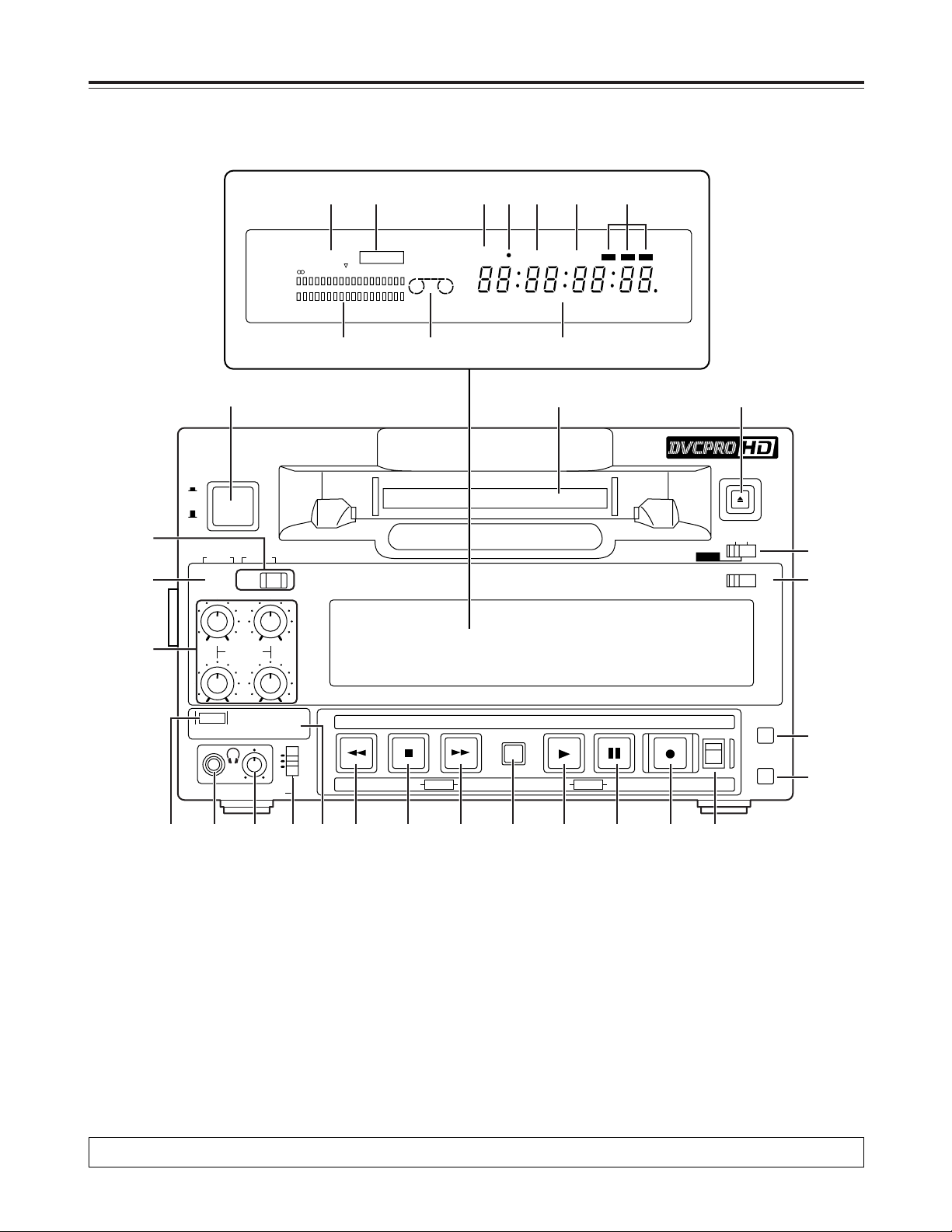
Parts and their functions
Front panel
Counter display
1 POWER switch
2 Cassette slot
Align the center of the cassette with the center of
the slot and push it gently inside.
The cassette tape is loaded automatically.
3 EJECT button
When this is pressed, the tape is unloaded, and
several seconds later the cassette will be
automatically ejected.
When it is pressed while the counter display shows
the CTL display, the display will be reset.
4 REC/REC INH lamp
REC: The lamp lights during recording
2
.
REC INH:
The lamp lights when the cassette is set to the
accidental erasure prevention status.
It also lights when the REC INHIBIT switch Q is
set to the ON position. Recording operations
cannot be performed while it is lighted.
5 REMOTE lamp
This lights when the LOCAL/MENU/REMOTE
switch > is set to the REMOTE position.
2 This function is operational only when the AJ-YA120AG (optional accessory) has been installed.
8
Front panel
6 REPEAT lamp
This lights during repeat playback.
<Note>
The lamp flashes and repeat playback is not
performed if the counter display mode which has
been set using menu items No.161 [CTL (TC) BGN]
and No.162 [END] is at variance from the counter
display mode used for repeat playback.
7 SYSTEM format lamp
This indicates the status of the mode which has
been selected by menu item No.15 [SYSTEM
FREQ].
On: 59/60 Hz mode
Off: 50 Hz/25 PsF mode
Flashing: 23/24 Hz mode2, 25 Hz mode
2
8 SCH lamp
2
When SD signals are supplied to the HD/SD REF
VIDEO IN connector, this lights while the subcarrier
phase of the signals is within the prescribed range.
9 SERVO lamp
This lights when the drum servo or capstan servo is
locked.
: Channel condition lamps
The lamp corresponding with the error rate status
lights to indicate the channel condition.
(Green 5 white 5 red)
Green : This lights when the error rates of both the
video and audio playback signals are
satisfactory.
White : This lights when the error rate of either the
video playback signals or audio playback
signals has deteriorated. Normal playback
images appear even while it is lighted.
Red : This lights when correction or interpolation
is initiated for either the video playback
signals or audio playback signals.
; Level meter
This indicates the levels of the audio signals.
The levels of the input signals are shown during
recording2or E-E2selection, and the levels of the
output signals are shown during playback.
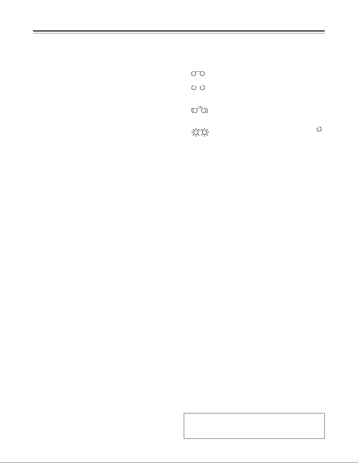
< Cassette insertion/tape travel indicator lamp
This lights when a cassette is inside the unit.
: This appears when a tape is inserted and
the STANDBY ON mode is established.
: This appears when a tape is inserted and
the STANDBY OFF (HALF LOADING)
mode is established.
: This appears when the tape is traveling,
and the segment display moves as the
tape travels.
: When the fan has shut down, the “”
corresponding to the stopped side flashes.
= Counter display
This displays the TC and CTL counts, user’s bit
(UB), remaining tape length and total tape length as
well as the on-screen information and other
messages.
If the voltage drops when the unit is powered with
DC power supply, the display flashes to provide a
warning.
When the voltage drops down to 10.6 V or so, the
unit’s power is automatically turned off. (When
“TYPE-A” or “TYPE-B” is not selected as the menu
item No.180 [BATTERY SEL] setting)
CTL, TC and UB lamps
The corresponding lamps flash when the TC and
UB information cannot be read during playback.
The lamps remain lighted when the information can
be read properly.
> LOCAL/MENU/REMOTE switch
Use this switch to select the menu settings or
control the unit from an external device.
LOCAL:
Select this position when the unit is to be
operated using the controls on its operation
panel.
MENU:
Select this position to perform on-screen menu
settings.
REMOTE:
Select this position when the unit is to be
operated using the external remote controller
(AJ-A95).
Parts and their functions
2 This function is operational only when the AJ-
YA120AG (optional accessory) has been
installed.
9
? ANALOG lamp
2
This lights when ANALOG is selected for the audio
input signals as the menu item No.700 [AUDIO IN
SEL] setting. When it is off, the HD SDI signal input
or INT SG status is established.
<Note>
The signals which are input for each of the
channels when analog signals are supplied are
recorded on the following audio tracks of the tape.
CH1 input 5CH1 and CH5 tracks
CH2 input 5CH2 and CH6 tracks
CH3 input 5CH3 and CH7 tracks
CH4 input 5CH4 and CH8 tracks
@ METER button and lamp (CH3•4)
Each time the METER button is pressed, the
signals which are output to the headphone jack E
and represented on the level meter display are
switched between CH1/CH2 and CH3/CH4.
When the CH1/CH2 signal levels are displayed, the
CH3•4 lamp goes off.
<Note>
The METER button takes effect when LINE is
selected as the menu item No.780 [AUD OUT SEL]
setting for the analog audio output connectors.
A Audio output lamps (CH1•2, CH3•4)
The audio channels to which the signals are output
are indicated by these lamps.
B Audio monitor selector switch
This is used to select the audio monitor output and
headphone output channel.
Parts and their functions
Front panel
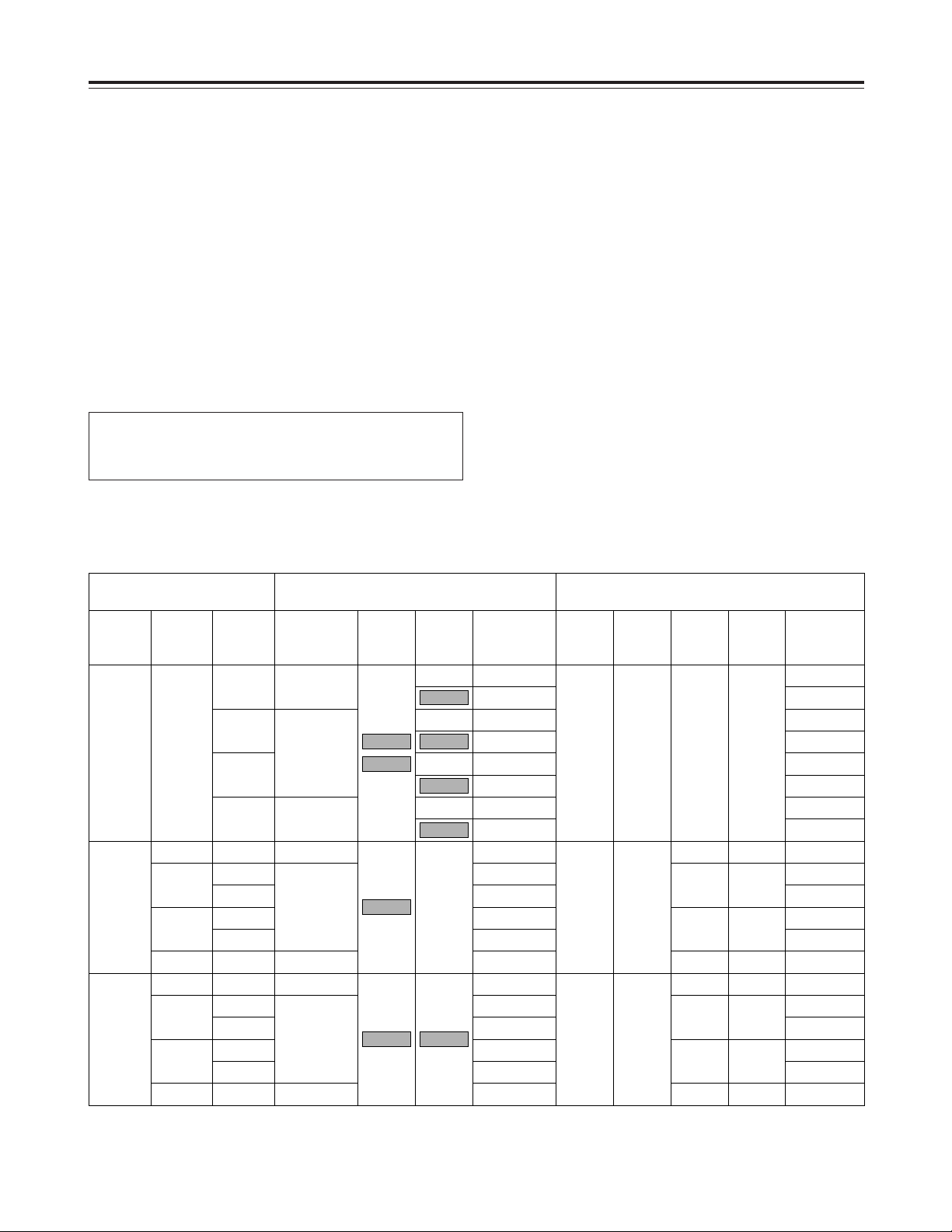
Reference:
Combination of setup menu items and audio outputs selected by the front panel switches
2 This function is operational only when the AJ-
YA120AG (optional accessory) has been
installed.
Setup menu item
No.780
AUD OUT
SEL
No.770
MONITOR
MIX
No.771
H.PHONE
MIX
Front panel
Audio monitor
selector switch
B
Audio
output
lamps
A
METER
lamp
@
Headphone
output
AUDIO
MONITOR
Rear panel
AUDIO OUT connectors
CH1 CH2 CH3/L CH4/R
LINE
CH1/2
CH3/4
——
——
STEREO
CH1+2
——
——
STEREO
CH1+2
——
——
STEREO
CH1+2
——
——
STEREO
CH1+2
STEREO
CH1+2
——
——
STEREO
CH1+2
STEREO
CH1+2
——
CH1
ST
CH2
CH1
ST
CH2
CH1
ST
CH2
Off
Off
Off
Off
Off
L=R (CH1)
L=R (CH3)
L=CH1/R=CH2
L=CH3/R=CH4
L=R (CH1+2)
L=R (CH3+4)
L=R (CH2)
L=R (CH4)
L=R (CH1)
L=CH1/R=CH2
L=R (CH1+2)
L=CH1/R=CH2
L=R (CH1+2)
L=R (CH2)
L=R (CH3)
L=CH3/R=CH4
L=R (CH3+4)
L=CH3/R=CH4
L=R (CH3+4)
L=R (CH4)
L=R (CH1)
L=R (CH3)
L=CH1/R=CH2
L=CH3/R=CH4
L=R (CH1+2)
L=R (CH3+4)
L=R (CH2)
L=R (CH4)
L=R (CH1)
L=CH1/R=CH2
L=R (CH1+2)
L=CH1/R=CH2
L=R (CH1+2)
L=R (CH2)
L=R (CH3)
L=CH3/R=CH4
L=R (CH3+4)
L=CH3/R=CH4
L=R (CH3+4)
L=R (CH4)
CH1
CH1
CH3
CH2
CH2
CH4
CH3
L=CH1
L=CH1
L=CH1+2
L=CH2
L=CH3
L=CH3
L=CH3+4
L=CH4
CH4
R=CH1
R=CH2
R=CH1+2
R=CH2
R=CH3
R=CH4
R=CH3+4
R=CH4
CH3•4
CH3•4CH1•2
CH3•4
CH3•4
CH3•4CH3•4
CH3•4
CH3•4

10
C Analog audio signal recording level controls
2
These are used to adjust the recording levels of the
analog audio signals for CH1, CH2, CH3 and CH4
(coupled to CH5, CH6, CH7 and CH8).
These are “pull for variable” controls: pull up a
control to adjust it. If a control is pulled down, the
signals of the corresponding channel are set to the
default level.
<Note>
These controls cannot be used to adjust the levels
of HD digital audio signals.
D 720p lamp
This lights when the 720p system is selected.
E Headphone jack
When stereo headphones are connected to this
jack, the recording2or playback sound can be
monitored through the headphones.
F Volume control
This is used to adjust the headphones volume.
G REW button
Press this to rewind the tape.
While the button is held down in one of the search
modes (search still, FWD search, FWD search still
or REV search still), the REV search mode is
established, and the tape is reviewed at the speed
selected using menu item NO.150 [SEARCH
SPEED]. (See page 17)
When the button is pressed in one of the slow
modes (slow still, FWD slow or FWD slow still), the
tape is played back at the REV linear 0.3k speed.
(See page 18)
H STOP button
When this is pressed, the tape stops traveling, and
when the TAPE/EE switch N is set to TAPE, still
images can be monitored.
The cylinder continues to rotate even in the stop
mode, and the tape remains tightly wound around
it.
When the unit has been in the stop mode for a
period exceeding the prescribed time, it is
automatically set to the standby OFF (half loading)
mode in order to protect the tape.
The stop mode is established immediately after a
tape is inserted into the unit.
When a still image is displayed, noise may appear
on the monitor: this is normal and not indicative of
trouble.
I FF button
Press this to fast forward the tape.
While the button is held down in one of the search
modes (search still, REV search, REV search still
or FWD search still), the FWD search mode is
established, and the tape is cued at the speed
selected using menu item NO.150 [SEARCH
SPEED]. (See page 17)
When the button is pressed in one of the slow
modes (slow still, REV slow or REV slow still), the
tape is played back at the FWD linear 0.3k speed.
(See page 18)
J SEARCH button
When this is pressed, the unit is set to the search
mode or slow mode. (See pages 17, 18)
K PLAY button
Press this to start playback.
Recording starts when it is pressed together with
the REC button.
L PAUSE/STILL button
When this is pressed during recording, the tape
temporarily stops (pauses). When it is pressed
again, recording
2
is resumed.
When it is pressed during playback, a still image
appears. When it is pressed again, playback is
resumed.
When it is pressed during FWD or REV search, the
tape pauses (FWD or REV search still). When it is
pressed again, the FWD or REV search is
resumed.
When it is pressed during FWD or REV slow
playback, the tape pauses (FWD or REV slow still).
When it is pressed again, the FWD or REV slow
playback is resumed.
In the FWD or REV slow playback mode, the tape
is played back at the linear 0.3k speed.
When the tape pauses, noise may appear on the
monitor: this is normal and not indicative of trouble.
(See page 18)
Parts and their functions
Front panel
2 This function is operational only when the AJ-
YA120AG (optional accessory) or AJ-YAD120AG
(optional accessory) has been installed.

11
Parts and their functions
M REC button
2
No optional board installed
This unit is a video cassette player so it cannot
record by pressing the REC button.
When the REC button is pressed, the REC INH
lamp on the counter display lights for several
seconds. When T&S&M has been selected as
the menu item No.006 [DISPLAY SEL] setting,
“NO OPTION FOR REC” appears in the
superimposed mode display area.
When the AJ-YA120AG or AJ-YAD120AG is
installed
When the REC button is pressed together with
the PLAY button, recording starts. When it is
pressed during stop or eject, the input video
signals and audio signals can be checked even
when the TAPE/EE switch is set to TAPE.
The value of the time code generator can also be
checked. (REC CHECK mode)
The REC CHECK mode is released when the
STOP button or other operation button is
pressed.
N TAPE/EE switch
This is used to select the signals which are to be
output in the STOP mode.
TAPE:
The signals played back from the tape are
output.
EE:
No optional board installed
The signals selected by menu item No.106
[EJECT EE SEL] are output. The black signal
for the video signals and mute for the audio
output are the factory settings.
When the AJ-YA120AG or AJ-YAD120AG is
installed
The signals selected by menu item No.600
[VIDEO IN SEL] are output as the video
signals, and the signals selected by menu item
No.700 [AUDIO IN SEL] are output as the
audio signals.
However, when “1394” is selected as the
VIDEO IN SEL setting, the audio input signals
will also be supplied from the DV connector
(digital video interface).
<Note>
The image and sound may be disrupted when this
switch’s position is changed.
Front panel
P RESET button
When this is pressed in the CTL mode, the counter
display is reset to zero.
Q REC INHIBIT switch
2
This is used to enable or disable recording on the
cassette tape.
ON : Recording on the cassette tape is disabled.
The REC INHIBIT lamp on the display
lights.
OFF : When the cassette tape’s accidental
erasure prevention mechanism is at the
recording enable setting, recording onto the
cassette tape is enabled.
O COUNTER button
This is used to switch the counter display.
Each time it is pressed, the display is switched by
one step in the following sequence: CTL 5 TC 5
UB 5 r 5 PB FORMAT 5 CTL and so on.
CTL : The tape timer (control signal) is displayed.
TC : The time code is displayed.
UB : The user’s bit is displayed.
r:The remaining tape length and total tape
length are displayed in 1-minute
increments.
Example:
r30-46 = 30 minutes of tape remaining
out of a total tape length of 46 minutes
PB FORMAT:
The format of the tape now playing is displayed.
Counter displayPlayback tape format
DVCPRO HD-LP (1080i)
DVCPRO HD-LP (720P)
DVCPRO HD (1080i)
DVCPRO HD (720P)
DVCPRO50 (422)
DVCPRO (411)
DVCPRO50 (420P)
DV
DVCAM
Hd 1080
Hd 720P
Hd 1080 SP
Hd 720P SP
Sd 50
Sd 25
Sd 50P
The DV lamp on the counter
display lights.
–––—
2 This function is operational only when the AJ-
YA120AG (optional accessory) or AJ-YAD120AG
(optional accessory) has been installed.
12
PUSH PUSH
AUDIO IN
(OPTION)
PUSH PUSH
CH
1
CH
2
CH
3
CH
4
CH
1
CH
2
CH
3
CH
4
TC
HD/SD REF VIDEO IN
VIDEO OUT
IN
OUT
L
R
DC OUT
DC IN
SIGNAL
GND
FUSE 250V T2.5AH
F1
AC IN
12V 250mA
R
E
M
O
T
E
AUDIO OUT
(OPTION)
(OPTION)
75Ω
ON
1
2
(SUPER)
Y/G
P
B
/B
P
R
/R
OFF
LR
MONITOR
AUDIO
MON
OUT
1
2
3
4
5
6
7
=
=
8
?
<
;
9
:
>
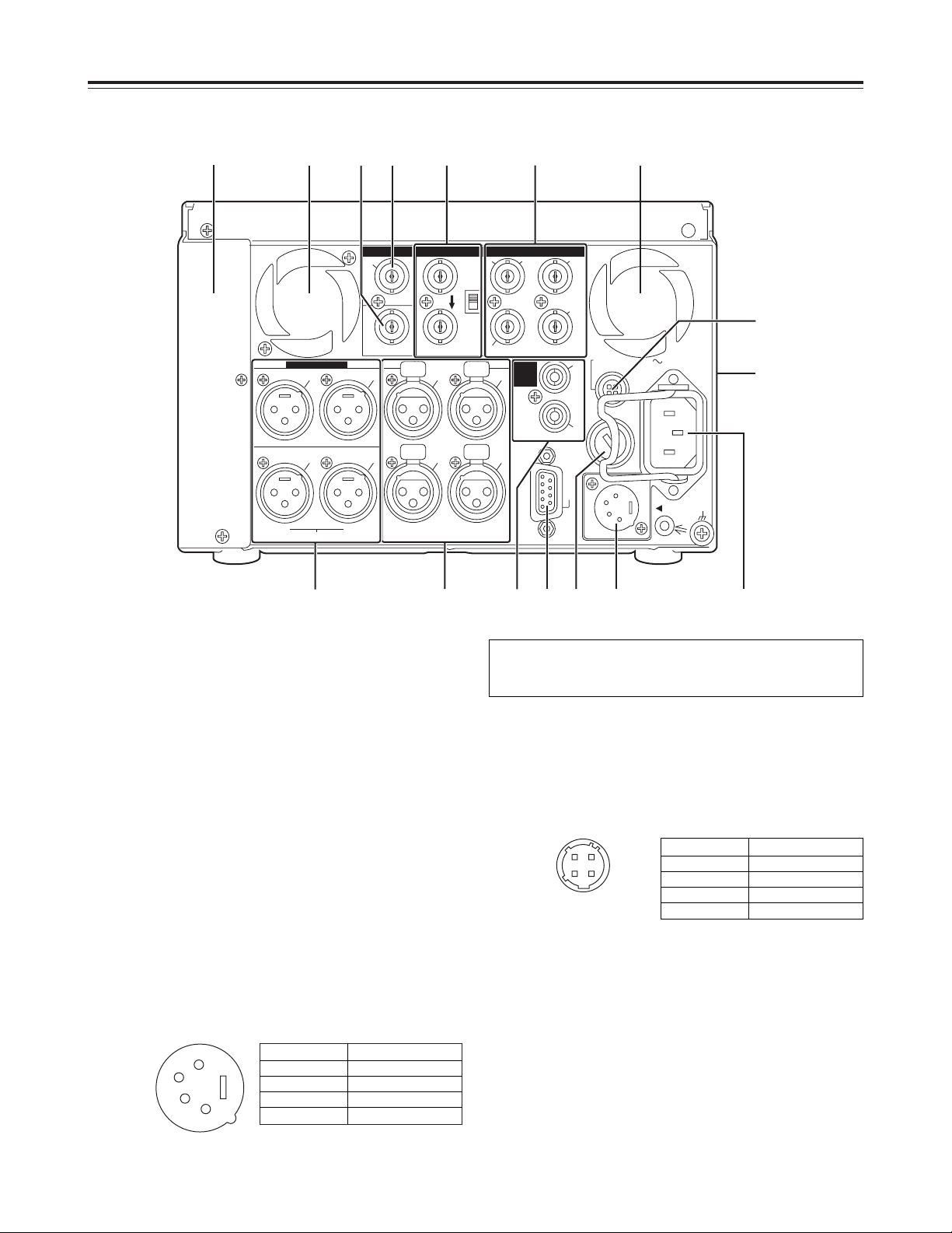
Rear panel
Parts and their functions
1 AC IN inlet
This is the AC power inlet.
Connect the accessory power cable here.
When both an AC power supply and DC power
supply have been connected, the AC power supply
takes priority.
2 DC IN socket
This is the input connector for the DC 12V supply
voltage.
Use the optional AC adapter (AJ-B75 or AJ-B95).
When the voltage has dropped to around 10.6V, the
unit’s power is automatically turned off. (When
“TYPE-A” or “TYPE-B” is not selected as the menu
item No.180 [BATTERY SEL] setting)
Even when the supply voltage is restored later, the
power will not automatically come back on. The
POWER switch must be set to OFF and then back
to ON several seconds later.
When both AC power supply and DC power supply
are connected, the AC power supply takes priority.
3 DC OUT socket
This is the DC 12V output socket.
Power is supplied from here to the external remote
controller (AJ-A95).
The DC power cable is packed together with the
AJ-A95.
4 Fuse holder
This holds the AC 250 V/2.5 A fuse (time lag type).
<Note>
Use the fuse specified by Panasonic.
3
1
2
4
1
2
3
4
<Note>
Supplying +12V power to the GND terminal by mistake may give
rise to ignition, resulting in a fire, or it may cause injury.
Pin No.
1
2
3
4
Signal
Ground
–––
–––
+12 V
Pin No.
1
2
3
4
Signal
Ground
–––
–––
+12 V
13
Rear panel
Parts and their functions
1
6
9
5
= Fan motor
This is provided to cool off the unit.
> Grips
Grips are provided on both sides of the unit, but the
unit should be placed on a flat, level surface for
operation.
? Option panel
When the AJ-YA120AG or AJ-YAD120AG option is
to be installed, remove this panel, and replace it
with the panel packed with the option.
For details on installation, refer to the instructions
accompanying the option concerned.
: AUDIO OUT/MONITOR connector (CH1, CH2,
CH3, CH4)
These are the output connectors for the analog
audio signals.
The CH3 and CH4 connectors are also used as the
audio monitor output connectors (left and right
channels). (See page 9)
; AUDIO MONITOR connectors
These are the audio monitor output connectors.
The same signals are output as the headphone
output signals.
<Note>
The output signal level is fixed.
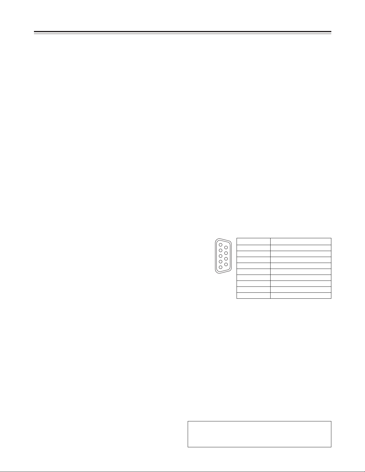
< REMOTE CONTROL connector
An external remote controller (AJ-95: optional
accessory) is connected here to enable the unit to
be operated using an external device.
<Notes>
O Set the LOCAL/MENU/REMOTE switch to
REMOTE.
O The connector satisfies the RS-422A interface
standard, but no editing-related functions are
operational.
5 VIDEO OUT (1, 2, Y/G, P
B/B, PR/R) connectors
By changing the menu item No.615 [V OUT SEL]
setting, either analog composite video signals or
HD analog component Y (or G) signals are output
from the VIDEO OUT1 connector.
By selecting the menu item No.616 [OUT MATRIX]
setting, Y/P
B/PR or R/G/B signals can be selected
as the HD analog component signals.
Video signals with superimposed information
embedded can be output from the VIDEO OUT2
connector.
Whether superimposed information is to be
embedded in the signals is selected using menu
item No.005 [SUPER].
<Notes>
O When HD analog component output or HD SDI
output
2
signals are output with the 60 Hz or 24
Hz system frequency, the SD SDI2signals will
be output without the sync signals (NO SYNC),
and the analog composite signals will be output
in the black-and-white mode (burst OFF).
O A dummy sync signal for preventing the monitor
from operating incorrectly is added to the sync
signals in the RGB output.
6 TC IN connector
2
This is used to record an external time code onto
the tape.
7 TC OUT connector
This is used to output the playback time code
during playback.
During recording2, the time code generated by the
internal time code generator is output from this
connector.
8 HD/SD REF VIDEO IN connectors and 75Ω
termination switch
2
These are the input connectors for the HD/SD
reference video signal. For termination, set the
switch to ON.
<Notes>
O When inputting an HD reference signal to the
connector, input a tri-level sync signal with
positive and negative polarities. Also, supply
signals matching the input signals and tape
format.
O When inputting an SD reference signal to the
connector, use composite video signals which
satisfy the RS-170A standard or a black burst
signal.
9 AUDIO IN connectors (CH1, CH2, CH3, CH4)
2
These are the input connectors for the analog audio
signals.
Pin No.
1
2
3
4
5
6
7
8
9
Signal
Frame Ground
Transmit A
Receive B
Receive Common
––—–
Transmit Common
Transmit B
Receive A
Frame Ground
2 This function is operational only when the AJ-
YA120AG (optional accessory) has been
installed.
14
Tapes
Align the cassette with the center of the slot and push
it gently inside.
The cassette tape is loaded automatically.
Inserting the tape
Usable tapes
POWER
ON
OFF
AUDIO SELECT
AUDIO OUT SEL
AUDIO MON SELECT
INPUT
ANALOG
PULL
FOR VAR
CH
3-4
720 PCH1·2CH3·4
CH
1
REC
CH
2
CH
3
CH
4
CH1
ST
CH2
METER
TAPE
PAUSE/STILL
SEARCH
FFSTOPREW PLAY
REC(OPTION)
EJECT
LOCAL
OFF ON
REC INH (OPTION)
REMOTE
MENU
COUNTER
RESET
EESETs DATA rMODEDOWN MENU UPPAGE
M cassette size
L cassette size
Consumer DV, DVCAM cassettes
Standard DV, DVCAM cassettes
Mini DV, DVCAM cassettes
Note that long-playing mini DV cassette tapes
(80 minutes in standard mode, 120 minutes in
long-playing mode) cannot be used.
For consumer DV tapes, Panasonic
recommends the Panasonic brand.
M cassettes
DVCPRO HD-LP
Tapes with up to 33 minutes of
recording/playback (AJ-HP33EMG)
DVCPRO 25/50/50P HD playback tapes
L cassettes
DVCPRO HD-LP
Tapes with up to 92 minutes of
recording/playback (AJ-HP64ELG, AJHP92ELG)
DVCPRO 25/50/50P HD playback tapes
Precautions for using consumer DV and DVCAM
cassettes
O Use a cassette adapter (AJ-CS455P) when using
mini DV or DVCAM cassette tapes.
Inserting a mini DV or DVCAM cassette tape into
the unit without using a cassette adapter may
cause trouble or malfunctioning.
O Tapes recorded in the LP modes cannot be
played back.
O When editing material recorded on a consumer
DV or DVCAM cassette tape, record the material
onto a DVCPRO tape or onto another broadcast
VTR before use.
O The maximum transport speed of a mini DV or
DVCAM cassette tape is 32x normal tape speed.
O The images may be disrupted when a consumer
DV or DVCAM cassette tape is played back in a
slow motion mode.
O To protect your tapes, refrain as much as
possible from repeatedly cueing up the tapes in
consumer DV or DVCAM cassettes at the same
place.
O When consumer DV or DVCAM cassette tapes
are used, the maximum STILL TIMER time is set
to 10 seconds.
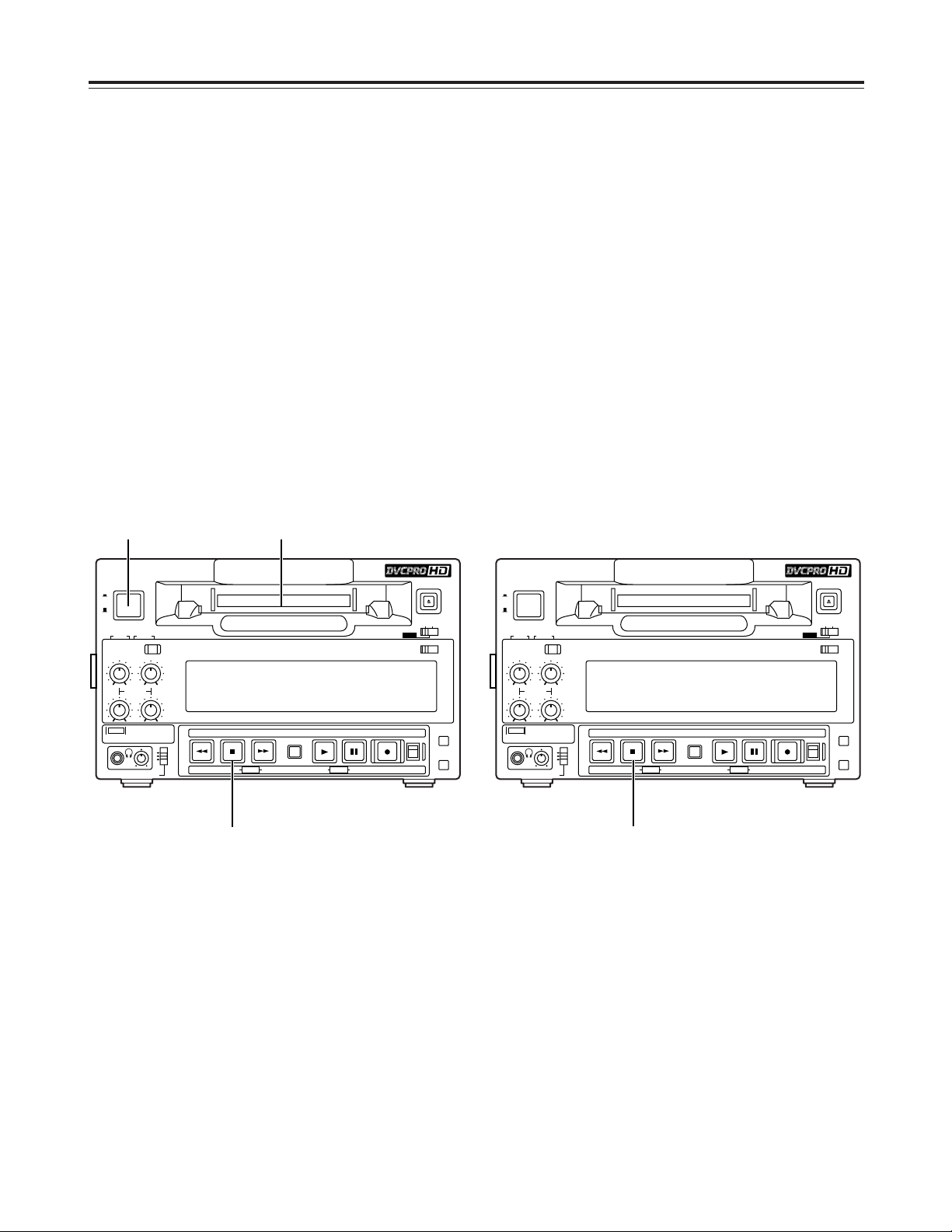
15
STOP mode
POWER
ON
OFF
AUDIO SELECT
AUDIO OUT SEL
AUDIO MON SELECT
INPUT
ANALOG
PULL
FOR VAR
CH
3-4
720 PCH1·2CH3·4
CH
1
REC
CH
2
CH
3
CH
4
CH1
ST
CH2
METER
TAPE
PAUSE/STILL
SEARCH
FFSTOPREW PLAY
REC(OPTION)
EJECT
LOCAL
OFF ON
REC INH (OPTION)
REMOTE
MENU
COUNTER
RESET
EESETs DATA rMODEDOWN MENU UPPAGE
1
POWER
ON
OFF
AUDIO SELECT
AUDIO OUT SEL
AUDIO MON SELECT
INPUT
ANALOG
PULL
FOR VAR
CH
3-4
720 PCH1·2CH3·4
CH
1
REC
CH
2
CH
3
CH
4
CH1
ST
CH2
METER
TAPE
PAUSE/STILL
SEARCH
FFSTOPREW PLAY
REC(OPTION)
EJECT
LOCAL
OFF ON
REC INH (OPTION)
REMOTE
MENU
COUNTER
RESET
EESETs DATA rMODEDOWN MENU UPPAGE
Operation
<Precaution for STILL TIMER setting>
O If the same locations on the same tape are
repeatedly used, the cumulative standby time at
these same locations will continue to mount up. To
protect your tapes, minimize the amount of standby
time at the same locations on the tapes.
Turning on the unit’s power
1 2
3
Turn on the unit’s power.
1
When the STOP button is pressed, the unit is
set to the STOP mode.
The STOP lamp lights, and the tape stops
traveling.
O In order to protect the tape inside the unit, the
unit is set to the tape protection mode when
the time selected as the menu item No.400
[STILL TIMER] has elapsed.
When the STOP, REW, FF or PLAY button is
pressed, the unit is transferred to the
corresponding mode.
1
Insert a cassette tape.
Insert the cassette tape at the correct position
without forcing it in any way.
2
Check that the STOP lamp has lighted.
As soon as the tape is inserted, the cylinder
starts rotating automatically, the tape is loaded,
and the unit is set to the stop mode.
3
<Notes>
O Before turning off the power, press the EJECT
button to eject the cassette.
O When ON is selected as the menu item No.104
[REF ALARM] setting, the STOP button’s lamp will
flash if the reference video input signal is not
supplied.
Before attempting to operate the unit, check whether
the equipment has been connected properly.
Ensure that the unit is placed on a flat, level surface
for operation.

16
Operation
<Note>
Check that the SERVO lamp remains lighted during
recording. When it flashes or it is off, the playback
images will be disrupted.
This function can be used only when the AJ-YA120AG
(optional accessory) has been installed.
Recording
Pause/recording
(follow-on recording)
Press the PAUSE/STILL button while the
cassette tape is playing back.
1
Press the REC button to set the unit to the
REC PAUSE mode.
The monitor display now switches to the E-E
screen.
When REC-P or ALL has been selected as the
menu item No.154 [AUTO BACK] setting, the
tape will be rewound for several seconds from
the position where the PAUSE/STILL button was
pressed.
2
Press the PAUSE/STILL button to start
recording.
The tape now runs as far as the position where
the PAUSE/STILL button was pressed in step 1,
and recording commences.
<Note>
The E-E screen is now displayed.
3
Press the PAUSE/STILL button again to
temporarily stop the recording.
When REC-P or ALL has been selected as the
menu item No.154 [AUTO BACK] setting, the
tape will be rewound for several seconds from
the position where the PAUSE/STILL button was
pressed, and then it will stop temporarily.
4
Follow-on recording can be performed by
repeating steps 3 and 4.
5
Set the cassette tape’s erasure prevention tab
to recording enable, and insert the tape.
1
1. Selecting the input audio signals
1) Connect the signals to be recorded.
2) Use menu item No.700 [AUDIO IN SEL] to
select the audio input signals.
<Note>
When “1394” is selected as the menu item
No.600 [VIDEO IN SEL] setting, the audio
signals are input from the DV connector (digital
video interface) regardless of the AUDIO IN
SEL setting.
2. Adjusting the analog audio levels
O Adjust the levels of the audio input signals
when analog audio signals have been
selected as the audio input signals.
When the audio recording level controls are
at their pushed-in positions, the audio
signals are recorded at the proper levels.
<Note>
When HD SDI signals or signals from the DV
connector (digital video interface) are selected
as the audio input signals, it is not possible to
adjust their level.
4
While holding down the REC button, press
the PLAY button.
The REC and PLAY lamps light, and recording
commences.
When ALL has been selected as the menu item
No.154 [AUTO BACK] setting, the tape is
rewound for several seconds from the position
where the REC and PLAY buttons were pressed.
The tape will run up, and recording will start from
the position where the REC and PLAY buttons
were pressed so that the new recording will
follow on from the previous recording with no
disruptions in the continuity of the images.
5
To end the recording, press the STOP button.
Recording now ends, and the unit is set to the
stop mode.
6
Press the STOP button to set the unit to the
STOP mode.
2
Selecting the input video signals
Use menu item No.600 [VIDEO IN SEL] to select
the video input signals.
3

17
Operation
Cue/review
When the FF or REW button is pressed while one of
the search modes (search still, FWD search, REV
search, FWD search still or REV search still) is
established, the tape is cued or reviewed at the speed
which was set using menu item No.150 [SEARCH
SPEED].
Furthermore, when the FF is pressed during cue or
the REW button is pressed during review, the cue or
review speed can be increased to 1.85x normal tape
speed. When the FF or REW button is pressed again,
the tape is restored to the speed which was set using
menu item No.150 [SEARCH SPEED].
When the SEARCH button is pressed in the FF mode
or REW mode, the tape first slows down to the speed
which was set using menu item No.150 [SEARCH
SPEED], and cue or review is then performed.
When the PAUSE/STILL button is pressed during cue
or review, the tape is temporarily stopped (paused).
When it is pressed again, cue or review is resumed.
Playback
Insert a cassette tape into the unit.
1
Press the PLAY button.
Normal playback now commences.
2
To end playback, press the STOP button.
The VTR is set to the stop mode.
3
<Notes>
O Check that the SERVO lamp remains lighted during
recording. When it flashes or it is off, the playback
images will be disrupted.
O When playback starts up, the images will be
disrupted for a moment.
Resulting VTR
operation
VTR operation
status
Button operated
SEARCH Search still
FF or REW FF or REW
PLAY or STOP
PLAY PLAY
STOP STOP
Any status
PLAY or STOP PLAY or STOP
SEARCH FWD search (cue)
FF
PLAY or STOP PLAY or STOP
SEARCH REV search (review)
REW
PAUSE/STILL or
SEARCH or REW
FWD search (cue)
REW REV search (review)
FWD search still
FF
FWD search speed
switching
PAUSE/STILL or
SEARCH or REW
REV search (review)
FF FWD search (cue)
REV search still
PLAY or STOP PLAY or STOP
FF FWD search (cue)
REW REV search (review)
Search still
SEARCH FF
REW REV search (review)
PAUSE/STILL FWD search still
FWD search (cue)
SEARCH REW
FF FWD search (cue)
PAUSE/STILL REV search still
REV search
(review)
REW
REV search speed
switching
Still image playback
Press the PAUSE/STILL button during playback.
When it is pressed again, normal playback is restored.
<Notes>
O No sound is heard during still image playback.
O Noise may appear on the still images.
 Loading...