

Panasonic aj-ufc1800 Operation Manual
Panasonic AJ-UFC1800
Universal Format Converter
System Reference, Ver. 1.11
Operating Software Level 1.49
June 15, 2000

Table Of Contents
GENERAL.....................................................................................................................................................................
VERVIEW
O
EATURES
F
PECIFICATIONS
S
................................................................................................................................................................. 3
.................................................................................................................................................................. 3
......................................................................................................................................................... 4
CONTROLS................................................................................................................................................................5
RONT PANEL
F
EAR PANEL
R
............................................................................................................................................................ 5
.............................................................................................................................................................. 7
CONNECTIONS ......................................................................................................................................................... 9
NPUT REFERENCE
I
UTPUT REFERENCE
O
LACK BURST REFERENCE
B
..................................................................................................................................................... 9
.................................................................................................................................................. 9
........................................................................................................................................ 9
OPERATION............................................................................................................................................................ 10
ASIC OPERATION
B
ILM MODE OPERATION
F
.................................................................................................................................................... 10
........................................................................................................................................... 11
MENU TREE.......................................................................................................................................................... 13
RONT PANEL CONTROLS
F
........................................................................................................................................ 15
Home Menu......................................................................................................................................................... 15
Preset Menu........................................................................................................................................................16
Video In Menus...................................................................................................................................................17
Video Out Menu..................................................................................................................................................17
Filter Menu ......................................................................................................................................................... 18
Timing Menu.......................................................................................................................................................18
Resize Menus....................................................................................................................................................... 19
Gain Menus......................................................................................................................................................... 20
Diagnostics Menu ...............................................................................................................................................21
Audio Menus .......................................................................................................................................................22
Test Menus..........................................................................................................................................................23
Setup Menus........................................................................................................................................................ 23
ERROR MESSAGES ............................................................................................................................................... 26
OTHERS......................................................................................................................... ........................................... 27
INDICATORS ........................................................................................................................................................ 27
EMOTE CONNECTORS
R
............................................................................................................................................. 28
2
Features Overview
Overview
The purpose of the AJ-UFC1800 is to create a spatial conversion from any input video format to any output video
format. The input may be any standard video format (high definition or standard definition), and the output may
also be any standard video format (high definition or standard definition) as long as it is has a related frame rate to
the input format. Frame rate conversion is not performed by the system, but frame rates from input to output may be
changed by the insertion or removal of 3:2 or 2:2 pull-down.
While performing a conversion, the end user will usually have to make additional adjustments regarding aspect
ratio, color space, audio & video timing adjustments, etc. The AJ-UFC1800 allows all of these types of adjustments
to be made using a simple front panel control system.
Features
- Conversion between most video formats with related frame rates. See table below.
- Special film modes to handle 3:2 pull-down and segmented frames.
- All digital processing, 10 bit, 4:2:2.
- 1035I <-> 1080I conversions in field or frame (3:2) mode.
- Extensive pan, zoom and crop function.
- Internal test pattern generator.
- 16 user presets with the first 8 remotely selected by GPI.
- Compact 3U size.
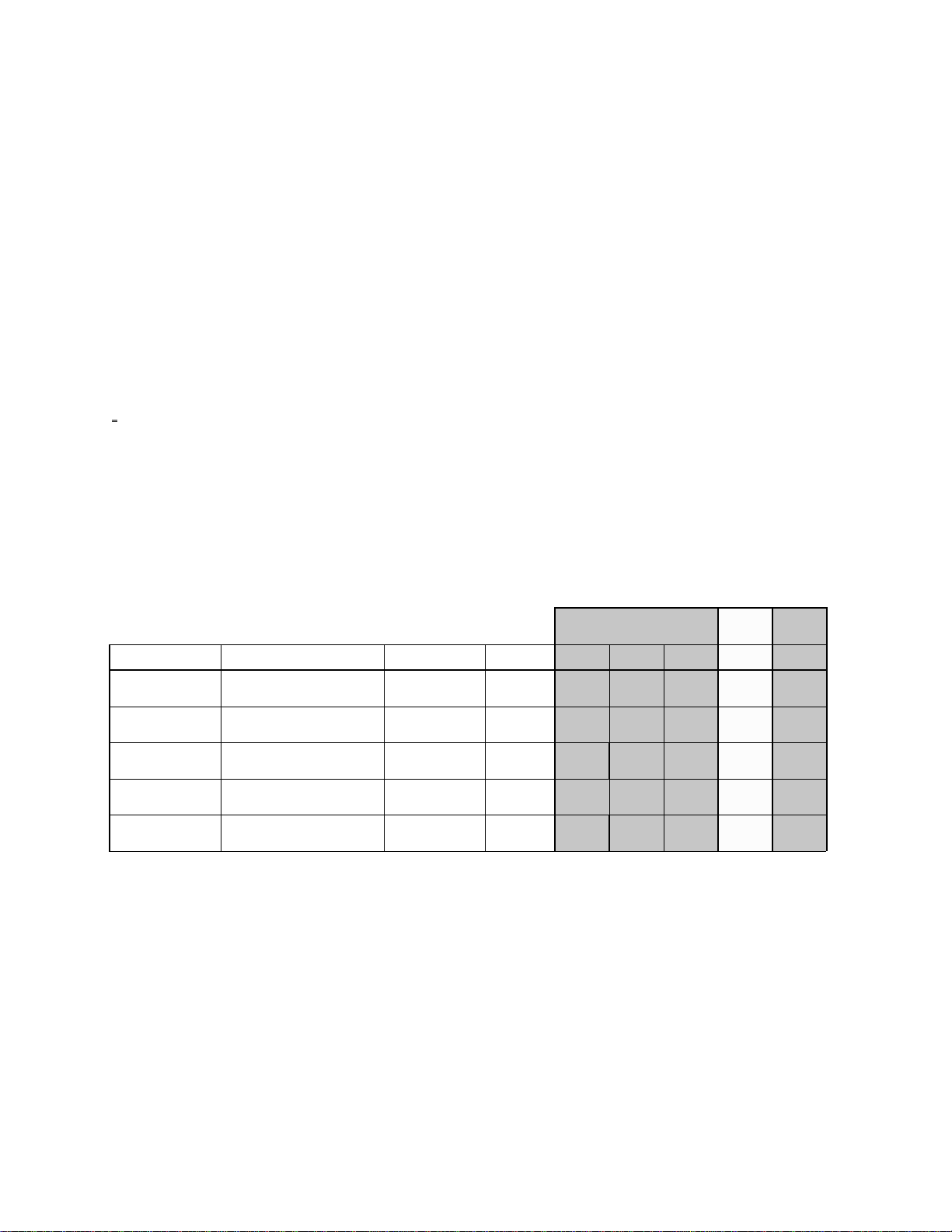
Group A GroupBGroup
C
Format Name Active Sample (H/V) Serial (bps) SMPTE 60p 60i 30p 50i 24p
1125i 1920 x 1080 (1035) 1.5G 292M
750p 1280 x 720 1.5G 296M
525i 720 x 483 270M 259M
525p 720 x 483 360M 294M
625i 720 x 576 270M 259M
Note: Conversions can be made between any formats within the same group. Conversion between Group A and
Group C are done using a 3:2 pull-down function.
•
•
• • • •
• •
• •
3

Specifications
[Power requirements:]
Power supply : AC100V-120V , 50-60Hz
AC220V-240V , 50-60Hz
Power consumption : 115W
[GENERAL:]
Operating temperature : 5 to 40 •
Operating humidity : 10% to 90%
Weight : 18 Kg
Dimensions : 424(W) x 133(H) x 500(D)
[VIDEO INPUTS:]
1 HD SDI input – SMPTE 292M (1080I/P, 720P, 1035I)
1 SD SDI input – SMPTE 259M, 294M (480P, 480I, 576I)
[VIDEO OUTPUTS:]
2 HD SDI outputs – SMPTE 292M (1080I/P, 720P, 1035I)
2 SD SDI outputs – SMPTE 259M, 294M (480P, 480I, 576I)
Output level adjustment: 0 - 1.4
Black level adjustment: +7.4 / -7.5 IRE
Video line advance adjustment: 0 - 7 H
System H phase adjustment: 0 - less than 1H
[SYNC:]
1 External sync reference input – analog bi-level or tri-level sync
loop thru with 75 ohm ON/OFF switch
1 Genlock output - bi-level (0 to –2V into 75 ohms) or tri-level (+/-300mV into 75 ohms)
[AUDIO:]
8 AES/EBU digital audio inputs
8 AES/EBU digital audio outputs
SMPTE 272M embedded audio
Output timing adjustment: 0 - 170ms
[TIME CODE:]
External Time Code input/output
Note: All previous I/Os are on BNC connectors.
[CONTROL:]
1 GPI control port – 8 contact closure sensors to activate system presets
1 RS-232 control port – for connection to a PC for system programming or remote control
Note: The control ports are 9 pin, D-sub. connectors.
[ACCESSORIES:]
Power cord, 1pc.
4

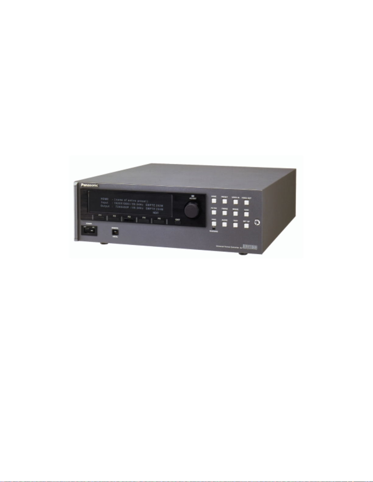
Controls
Front Panel
(1) POWER switch
(2) CONTROL switch
(3) Display panel
(4) Function buttons
(5) EXIT key
(6) ADJUST LED
(7) Control knob
After ON is pushed, it will take about 30 seconds for the system to initialize.
This is used to switch between operation from the front panel and the remote
connectors on the rear panel. When it is set to REMOTE, front panel operation is
disabled.
can be viewed, but they cannot be modified in this mode
LOCAL, the remote connector is disabled.
All menus are displayed on a 40x4 line character display.
F1-F5 follow the labels assigned to them for each system menu.
The EXIT key is used to go up one level in the system menus. At the top level, it
will cycle through the available menus.
This lights when the Control knob is active.
When the ADJUST LED is lit, this controls the selected function shown on the
display panel. If no adjustment is selected, it cycles through the choice of
menus.
The front panel will indicate this on all menus. Current settings
. When it is set to
5

(8) HOME key
Selects the HOME menu. This displays the selected conversion and allows all
settings to be viewed.
(9) PRESET key
(10) VIDEO IN key
(11) VIDEO OUT key
(12) FILTER key
(13) TIMING key
(14) RESIZE key
(15) GAIN key
(16) DIAG key
(17) WARNING LED
Selects the PRESET menu. Allows up to sixteen system configurations to be
saved and/or restored.
Selects the VIDEO IN menu. Allows the selection of SD and HD video inputs,
auto input detection and film modes .
Selects the VIDEO OUT menu. Allows the selection of SD and HD video outputs
and field versus frame filtering for film derived outputs.
Selects the FILTER menu. H and V filters and enhancement levels can be
adjusted from this menu.
Selects the TIMING menu. Reference selections and video phasing can be
adjusted from this menu.
Selects the RESIZE menu. Pan, zoom and crop adjustments can be made here.
Selects the GAIN menu. Video gain and black level adjustments can be made
here.
Selects the DIAGnostics menu. When the warning light (17) is illuminated, error
messages can be viewed here. The status of all monitored systems can also be
viewed here.
Signals a potential system problem. This will not light for masked errors.
(18) AUDIO key
(19) TEST key
(20) SETUP key
Selects the AUDIO menu. Allows for audio channel mapping, synchronization
and delay adjustments.
Selects the TEST menu. Allows H, V and frame based test patterns to be
selected as the video input.
restored here.
Selects the SETUP menu. Background color, power-up mode,
password
and time code mapping selections are available here.
Frame patterns can also be saved and/or
system
6

Power supply section
Rear Panel
(1) AC input socket
(2) GND (ground) terminal
This is connected to the power outlet using the supplied cable.
It is recommended that this unit be grounded when connected to
other units.
Digital video input/output section
(3) SD SERIAL IN connector
(BNCx1
(4) HD SERIAL IN connector
(BNCx1)
(5) SD SERIAL OUT 1,2
connectors (BNCx2)
(6) HD SERIAL OUT 1,2
connectors (BNCx2)
)
SDTV serial digital signals are input to this connector.
HDTV serial digital signals are input to this connector.
SD serial digital signals are output from these connectors.
HD serial digital signals are output from these connectors.
Reference input/output section
(7) EXT SYNC IN
connectors (BNCx2
(8) LTC IN connector
(BNCx1)
(9) GENLOCK SYNC OUT
connector (BNCx1)
(10) LTC OUT connector
(BNCx1)
)
Tri-level/bi-level sync signals or black burst signal are input to
these connectors as the reference signal. A loop-through format
and a 75Ω termination switch are provided.
The time code signals are input to this connector.
The tri-level/bi-level sync signals, for genlocking external inputs,
are output from this connector.
The time code signals are output from this connector.
7

Remote control section
(11) GPI connector (9P
(12) REMOTE IN connector
(RS-232, 9P)
)
Switch closure remote control connector.
RS-232 serial remote input connector.
Digital audio input/output section
(13) DIGITAL AUDIO IN CH
1/2, 3/4, 5/6, 7/8
connectors (BNCx4
(14) DIGITAL AUDIO OUT CH
1/2, 3/4, 5/6, 7/8
connectors (BNCx4
)
)
AES digital audio signals are input to these connectors.
AES digital audio signals are output to these connectors.
8
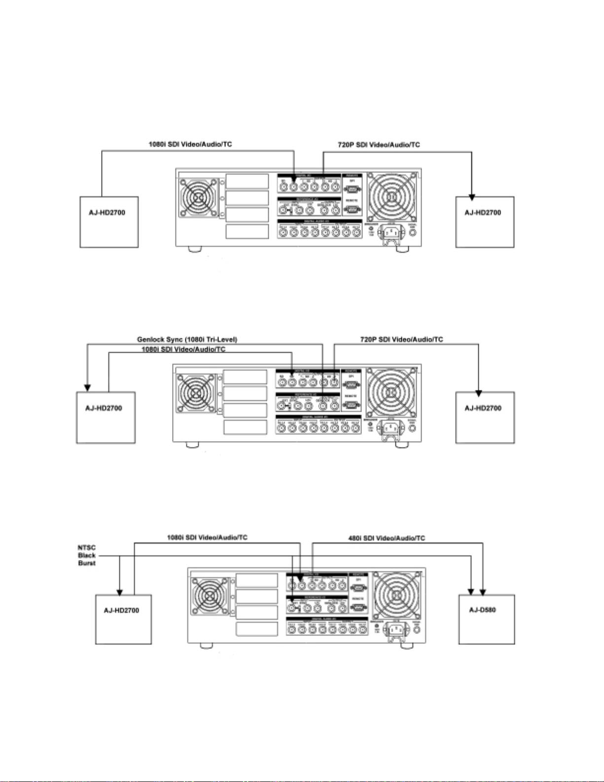
Connections
Input Reference
Output Reference
Missing output sync reference signal to EXT SYNC IN!
Black Burst Reference
9

Operation
Basic operation
VIDEO IN
FORMAT
Press VIDEO IN to select the input format and frame rate.
Press FORMAT(F1) to select an HxV value. Pressing the function key or turning the
knob will cycle through the range of choices. AUTO SD or AUTO HD will attempt to
detect the input format if a signal is present.
F RATE
Press F RATE(F2) to select the frame rate. Pressing the function key or turning the knob
will cycle through the range of choices. AUTO SD or AUTO HD will attempt to detect the
input format if a signal is present.
VIDEO OUT
FORMAT
Press VIDEO OUT to select the output format and frame rate.
Press FORMAT(F1) to select an HxV value. Pressing the function key or turning the
knob will cycle through the range of choices.
F RATE
Press F RATE(F2) to select the frame rate. Pressing the function key or turning the knob
will cycle through the range of choices.
This will set the system to nominal conversion settings. These settings can be modified under the
following menus.
FILTER
Press FILTER to change the conversion filters and to add enhancement.
H RESP
V RESP
H ENH
V ENH
2-D ENH
RESIZE
ZM MODE
Press H RESP(F1) to select a horizontal filter response. Pressing the function key or
turning the knob will cycle through the NARROW, STANDARD and WIDE choices.
Press V RESP(F2) to select a vertical filter response. Pressing the function key or
turning the knob will cycle through the NARROW, STANDARD and WIDE choices.
Press H ENH(F3) to add horizontal enhancement. Pressing the function key or turning
the knob will change the amount in 0.5dB steps.
Press V ENH(F4) to add vertical enhancement. Pressing the function key or turning the
knob will change the amount in 0.5dB steps.
Press 2-D ENH(F5) to add both horizontal and vertical enhancement at the edge of the
band. Pressing the function key or turning the knob will change the amount in 1dB steps.
This control may have limited effect on upconverted signals.
Press RESIZE to change the zoom, pan or crop settings. Press EXIT or turn the knob
until ZOOM/PAN is displayed. The double arrow “>>” signifies that multiple menus are
available at this level.
Press ZM MODE(F1) and select VARIABLE.
10

ZOOM H,V
Press ZOOM H(F2) and ZOOM V(F3) to change the zoom factor. This will lock the
horizontal and vertical adjustments together. Turn the knob to set the desired size.
EXIT
L, R, T, B
Press EXIT to go to the CROP menu.
Press LEFT(F1), RIGHT(F2), TOP(F3) or BOTTOM(F4) to remove portions of the input
frame. Small adjustments can be made by successively pushing the function keys or the
knob can be used to easily cover the full range of control.
EXIT
Press EXIT to view the resizing PRESETS menu. F1-5 are shortcut keys to select
popular picture sizes such as letterbox and 14x9.
If the output image does not completely cover the output frame, a black background will be displayed.
To change the background color, go to the SET UP menu.
SET UP
Press SET UP and then press EXIT or turn the knob until BACKGROUND COLOR is
displayed. The double arrow “>>” signifies that multiple menus are available at this level.
BG COL
Press BG COL(F1) to select a predefined color or select CUSTOM and then use F3-5 to
set the RGB values.
Film mode operation
For 24Hz progressive input:
VIDEO IN
FORMAT
F RATE
VIDEO OUT
FORMAT
F RATE
FLD/FRM
Press VIDEO IN to select the input format and 24Hz frame rate.
Press FORMAT(F1) to select an HxV progressive value. Pressing the function key or
turning the knob will cycle through the range of choices.
Press F RATE(F2) to select a 23.98/24Hz frame rate. Pressing the function key or
turning the knob will cycle through the range of choices.
Press VIDEO OUT to select the output format and frame rate. 24, 30, 48 and 60Hz rates
are all possible.
Press FORMAT(F1) to select an HxV value. Pressing the function key or turning the
knob will cycle through the range of choices.
Press F RATE(F2) to select the frame rate. Pressing the function key or turning the knob
will cycle through the range of choices. If a 29.97/30Hz or 59.94/60Hz rate is chosen,
then a 3:2 sequence is inserted. The sequence will be A Frame aligned with one hour
time code values whenever possible.
Press FLD/FRM(F3) to select field or frame filtering for 23.98/24Hz interlaced or
segmented frame outputs.
11

For 24Hz interlaced(segmented) input:
VIDEO IN
FORMAT
Press VIDEO IN to select the input format and 24Hz frame rate.
Press FORMAT(F1) to select an HxV interlaced value. Pressing the function key or
turning the knob will cycle through the range of choices.
F RATE
Press F RATE(F2) to select a 23.98/24Hz frame rate. Pressing the function key or
turning the knob will cycle through the range of choices.
PULLDN
Press PULLDN(F3) to select the 2:2 pull-down mode. Pressing the function key or
turning the knob will cycle through the range of choices.
Output selection is the same as above.
For 30/60Hz input:
VIDEO IN
FORMAT
Press VIDEO IN to select the input format and 30/60Hz frame rate.
Press FORMAT(F1) to select an HxV value. Pressing the function key or turning the
knob will cycle through the range of choices.
F RATE
Press F RATE(F2) to select a 29.97/30Hz or 59.94/60Hz frame rate. Pressing the
function key or turning the knob will cycle through the range of choices.
PULLDN
Press PULLDN(F3) to select the 3:2 pull-down mode. Pressing the function key or
turning the knob will cycle through the range of choices.
TIMING
3:2 REF
Press TIMING to select the 3:2 REFERENCE and A Frame position.
Press 3:2 REF(F4) to select the 3:2 pull-down reference. Pressing the function key or
turning the knob will cycle through the range of choices. EXT requires a special black
burst reference to be used (conforming to SMPTE 318). TIME CODE will use one hour
values as A Frame locations. MANUAL requires the position to be set each time the
input sequence is interrupted.
3:2 POS
Press 3:2 POS(F5) to select the A Frame position with respect to the 3:2 reference.
Pressing the function key or turning the knob will cycle through the range of choices.
This allows for manually setting the position or offsetting the position from normal
reference points.
Output selection is the same as above.
12

MENU TREE
HOME
PRESET
VIDEO IN
VIDEO OUT
FILTER
TIMING SYSTEM
F1 F2 F3 F4 F5
F1 F2 F3 F4 F5
SAVE RECALL TITLE DELETE (DETAILS)
TITLE
F1 F2 F3 F4
<- -> SP/CLR SAVE
F1 F2 F3
FORMAT F RATE PULLDN
F1 F2 F3
FORMAT F RATE FLD/FRM
F1 F2 F3 F4 F5
H RESP V RESP H ENH V ENH 2-D ENH
F1 F2 F3 F4
REF IN GL TYPE LIN ADV SYS H
FILM MODE
F1 F2 F3
“A” POS 3:2 REF TC SYNC
VERSION DEFAULTS
RESIZE
GAIN
ZOOM/PAN
F1 F2 F3 F4 F5
ZM MODE ZOOM H ZOOM V PAN H PAN V
CROP
F1 F2 F3 F4
LEFT RIGHT TOP BOTTOM
PRESETS
F1 F2 F3 F4 F5
FIT H FIT V FIT H&V 14:9 13:9
Y-Pr-Pb
F1 F2 F3 F4
YPrPbBLACK
CONV COLORIMETRY
F1 F2
INPUT OUTPUT
13

DIAG
AUDIO INPUT SELECTION
TEST SIG GEN
SETUP BACKGROUND COLOR
F1 F2 F3 F4 F5
ALL↓ MON’D↓ TRIG’D↓ RETRIG MON/MASK
ALL, MON’D, TRIG’D
F1 F3 F5
MASK TRG TYPE (RETRI G )
F1 F2
CH1-4 CH5-8
SYNCHRO
F1 F2
CH1-4 CH5-8
DELAY
F1
DELAY
F1 F2
SELECT F STORE
F1 F2 F3 F4
BG COL CUST R CUST G CUST B
POWER UP
F1 F2
STATE SELECT
TIME CODE-INPUT
F1
SOURCE
TIME CODE-OUTPUT
F1 F2 F3 F4 F5
EXT_LTC S_VITC VITC1 VITC2 DF MODE
(EXT_LTC) (S_VITC) (S_LTC) (DF_MODE)
LOCK
F1 F2 F3
PASSWD PRESETS CONTROLS
14

Front Panel Controls
All operation of the AJ-UFC1800 is performed by means of the front panel controls. These controls are used to
activate presets, select input and output formats, adjust control settings, and perform diagnostic testing. The front
panel consists of a 4x40 character display, 5 function buttons, an EXIT button, 12 menu buttons, and a control knob
for making adjustments. There is also a LOCAL/REMOTE switch to select either front panel or remote control
modes. In remote mode, the remote port is active and the front panel controls are ignored. In local mode, the front
panel is active and the remote ports are disabled.
All of the front panel menus, with descriptions of their operation are shown below. In all cases, the EXIT button
takes the user back to the previous menu.
Home Menu
The HOME menu is activated by pushing the HOME button on the UFC front panel. This menu shows what input
and output formats have been selected in the current configuration.
HOME
INPUT: 1920x1080I/29.97Hz
OUTPUT: 1280x720p/59.94Hz (UNLOCK)
VERSION DEFAULTS
F1 F2 F3 F4 F5 EXIT
F4 – Displays the current version of the system software.
F5 – Sets all parameters to factory default values. Input and output format selections are preserved. T his button
must be held for more than two seconds.
Turning the knob displays all of the system parameters that are currently set for this conversion.
INPUT FORMAT: 1920X1080I [F1]
INPUT F RATE: 29.97Hz [F2]
VIDEO INPUT PULLDOWN: OFF [F3]
VIDEO INPUT 3:2 REFERENCE: [N/A]
F1 F2 F3 F4 F5 EXIT
The function keys take you directly to the menu that sets the related para meter. If a given p arameter does not appl y
to the current set-up, then “[N/A]” will appear instead of a function key number. On returning to the HOME menu,
you will return to the same location in the menu. Pressing EXIT will return to the top display showing the input and
output formats.
15
 Loading...