

Page 1
Model No. AJ- P
Digital Video Cassette Recorder
Operating Instructions
Before operating this product, please read the instructions carefully and save this manual for future use.
VQT0N87
F1104W0 -F @
Printed in Japan
ENGLISH
Page 2
2
IMPORTANT
“Unauthorized recording of copyrighted television programs, video tapes and other materials may
infringe the right of copyright owners and be contrary to copyright laws.”
Operating precaution
Operation near any appliance which generates strong magnetic fields may give rise to noise in the video and
audio signals. If this should be the case, deal with the situation by, for instance, moving the source of the
magnetic fields away from the unit before operation.
CAUTION
RISK OF ELECTRIC SHOCK
DO NOT OPEN
CAUTION: TO REDUCE THE RISK OF ELECTRIC SHOCK,
DO NOT REMOVE COVER (OR BACK).
NO USER SERVICEABLE PARTS INSIDE.
REFER TO SERVICING TO QUALIFIED SERVICE PERSONNEL.
The lightning flash with arrowhead symbol,
within an equilateral triangle, is intended to
alert the user to the presence of uninsulated
“dangerous voltage” within the product’s
enclosure that may be of sufficient
magnitude to constitute a risk of electric
shock to persons.
The exclamation point within an equilateral
triangle is intended to alert the user to the
presence of important operating and
maintenance (service) instructions in the
literature accompanying the appliance.
$ THIS EQUIPMENT MUST BE GROUNDED
To ensure safe operation, the three-pin plug must be
inserted only into a standard three-pin power outlet
which is effectively grounded through the normal
household wiring.
Extension cords used with the equipment must have
three cores and be correctly wired to provide
connection to the ground. Wrongly wired extension
cords are a major cause of fatalities.
The fact that the equipment operates satisfactorily
does not imply that the power outlet is grounded or
that the installation is completely safe. For your
safety, if you are in any doubt about the effective
grounding of the power outlet, please consult a
qualified electrician.
WARNING:
• TO REDUCE THE RISK OF FIRE OR SHOCK
HAZARD, DO NOT EXPOSE THIS EQUIPMENT TO
RAIN OR MOISTURE.
• TO REDUCE THE RISK OF FIRE OR SHOCK
HAZARD, KEEP THIS EQUIPMENT AWAY FROM
ALL LIQUIDS-USE AND STORE ONLY IN
LOCATIONS WHICH ARE NOT EXPOSED TO THE
RISK OF DRIPPING OR SPLASHING LIQUIDS,
AND DO NOT PLACE ANY LIQUID CONTAINERS
ON TOP OF THE EQUIPMENT.
CAUTION:
TO REDUCE THE RISK OF FIRE OR SHOCK
HAZARD AND ANNOYING INTERFERENCE, USE
THE RECOMMENDED ACCESSORIES ONLY.
CAUTION:
TO REDUCE THE RISK OF FIRE OR SHOCK
HAZARD, REFER MOUNTING OF THE OPTIONAL
INTERFACE BOARD TO AUTHORIZED SERVICE
PERSONNEL.
CAUTION:
TO REDUCE THE RISK OF FIRE OR SHOCK
HAZARD, REFER CHANGE OF SWITCH SETTING
INSIDE THE DECK TO QUALIFIED SERVICE
PERSONNEL.
CAUTION:
Do not install or place this deck in a bookcase,
built-in cabinet or any other confined space in
order to maintain adequate ventilation. Ensure
that curtains and any other materials do not
obstruct the ventilation to prevent risk of electric
shock or fire hazard due to overheating.
CAUTION:
THE AC RECEPTACLE (MAINS SOCKET OUTLET)
SHALL BE INSTALLED NEAR THE EQUIPMENT
AND SHALL BE EASILY ACCESSIBLE.
TO COMPLETELY DISCONNECT THIS
EQUIPMENT FROM THE AC MAINS, DISCONNECT
THE POWER CORD PLUG FROM THE AC
RECEPTACLE.
CAUTION:
• Keep the temperature inside the rack to between
41°F to 104°F (5°C to 40°C).
• Bolt the rack securely to the floor so that it will
not topple over when the deck is drawn out.
indicates safety information.
Page 3

indicates safety information.
3
FCC Note:
This equipment has been tested and found to comply
with the limits for a class A digital device, pursuant to
Part 15 of the FCC Rules. These limits are designed
to provide reasonable protection against harmful
interference when the equipment is operated in a
commercial environment. This equipment generates,
uses, and can radiate radio frequency energy and, if
not installed and used in accordance with the
instruction manual, may cause harmful interference to
radio communications.
Operation of this equipment in a residential area is
likely to cause harmful interference in which case the
user will be required to correct the interference at his
own expense.
Warning:
To assure continued FCC emission limit compliance,
the user must use only shielded interface cables when
connecting to external units. Also any unauthorized
changes or modifications to this equipment could void
the user’s authority to operate it.
Notice (U.S.A.only):
This product has a fluorescent lamp that contains
a small amount of mercury.
It also contains lead in some components.
Disposal of these materials may be regulated in
your community due to environmental
considerations.
For disposal or recycling information please
contact your local authorities, or the Electronics
Industries Alliance:
<http://www.eiae.org.>
CAUTION:
This apparatus can be operated at a voltage in the
range of 100 – 240 V AC.
Voltage other than 120 V is not intended for U.S.A.
and Canada.
CAUTION:
Operation at a voltage other than 120 V AC may
require the use of a different AC plug. Please contact
either a local or foreign Panasonic authorized service
center for assistance in selecting an alternate AC
plug.
Page 4

4
Introduction
The AJ-SD965 is multi-purpose studio digital VTR
which utilize small, 1/4-inch wide cassette tapes for
high quality recording, playback and editing of video
images recorded at a rate of 50 Mbps in addition to
recording, playback and editing in DVCPRO (25 Mbps)
format.
This VTR incorporate digital compression technology
to dramatically reduce deterioration of picture quality
and sound resulting from dubbing, thereby attaining
high picture quality.
This unit also come equipped with a variety of
functions, such as assemble and insert functions,
which are necessary when performing editing
operations with a VTR.
A 3.5-inch color LCD monitor is also featured to allow
users to perform settings and monitor the display
images with consummate ease.
Contents
Introduction . . . . . . . . . . . . . . . . . . . . . . . . . . . . . . . .4
Features . . . . . . . . . . . . . . . . . . . . . . . . . . . . . . . . . . .5
Parts and their functions . . . . . . . . . . . . . . . . . . . . .7
Front panel . . . . . . . . . . . . . . . . . . . . . . . . . . . . . . .7
Display panel . . . . . . . . . . . . . . . . . . . . . . . . . . . . .16
Rear panel . . . . . . . . . . . . . . . . . . . . . . . . . . . . . . .18
Connections . . . . . . . . . . . . . . . . . . . . . . . . . . . . . .20
Tapes . . . . . . . . . . . . . . . . . . . . . . . . . . . . . . . . . . . .22
Jog/Shuttle . . . . . . . . . . . . . . . . . . . . . . . . . . . . . . .23
Manual editing . . . . . . . . . . . . . . . . . . . . . . . . . . . . .24
Preroll . . . . . . . . . . . . . . . . . . . . . . . . . . . . . . . . . . .24
Automatic editing (deck-to-deck) . . . . . . . . . . . . .25
Switch settings and adjustments . . . . . . . . . . . . . .25
Selecting the editing mode . . . . . . . . . . . . . . . . . .26
Registering the edit points . . . . . . . . . . . . . . . . . . .26
Checking and previewing edit points . . . . . . . . . . .27
Modifying edit points . . . . . . . . . . . . . . . . . . . . . . .28
Executing and reviewing automatic editing . . . . . .29
Audio split editing . . . . . . . . . . . . . . . . . . . . . . . . .30
Variable memory editing . . . . . . . . . . . . . . . . . . . .32
PF (Programmable Function) functions . . . . . . . .33
Setup (initial settings) . . . . . . . . . . . . . . . . . . . . . .34
Setup menus . . . . . . . . . . . . . . . . . . . . . . . . . . . . . .35
SYSTEM menu . . . . . . . . . . . . . . . . . . . . . . . . . . .38
USER menus . . . . . . . . . . . . . . . . . . . . . . . . . . . .40
<BASIC> . . . . . . . . . . . . . . . . . . . . . . . . . . . . . .40
<OPERATION> . . . . . . . . . . . . . . . . . . . . . . . .42
<INTERFACE> . . . . . . . . . . . . . . . . . . . . . . . . .45
<EDIT> . . . . . . . . . . . . . . . . . . . . . . . . . . . . . . .46
<TAPE PROTECT> . . . . . . . . . . . . . . . . . . . . .48
<TIME CODE> . . . . . . . . . . . . . . . . . . . . . . . . .49
<VIDEO> . . . . . . . . . . . . . . . . . . . . . . . . . . . . .51
<AUDIO> . . . . . . . . . . . . . . . . . . . . . . . . . . . . .55
<V BLANK> . . . . . . . . . . . . . . . . . . . . . . . . . . .58
<LCD> . . . . . . . . . . . . . . . . . . . . . . . . . . . . . . .61
<MENU> . . . . . . . . . . . . . . . . . . . . . . . . . . . . . .61
Time code/user bit . . . . . . . . . . . . . . . . . . . . . . . . .62
Superimpose screen . . . . . . . . . . . . . . . . . . . . . . .64
Video output signals and servo reference
signal . . . . . . . . . . . . . . . . . . . . . . . . . . . . . . . . . . . .65
Audio V fade function . . . . . . . . . . . . . . . . . . . . . . .67
Audio recording channel and monitor output
selection . . . . . . . . . . . . . . . . . . . . . . . . . . . . . . . . .68
Printed circuit board . . . . . . . . . . . . . . . . . . . . . . . .68
Rack mounting . . . . . . . . . . . . . . . . . . . . . . . . . . . .69
Video head cleaning . . . . . . . . . . . . . . . . . . . . . . . .70
Condensation . . . . . . . . . . . . . . . . . . . . . . . . . . . . .70
Maintenance . . . . . . . . . . . . . . . . . . . . . . . . . . . . . .70
Error messages . . . . . . . . . . . . . . . . . . . . . . . . . . . .71
RS-232C interface . . . . . . . . . . . . . . . . . . . . . . . . . .76
Connector signals . . . . . . . . . . . . . . . . . . . . . . . . .81
Specifications . . . . . . . . . . . . . . . . . . . . . . . . . . . . .83
Optional interface boards
O Analog Video Input Board
AJ-YA932G (625i), AJ-YA931G (525i)
O Digital Video Interface Board (IEEE 1394)
AJ-YAD955G
Use only the optional boards listed above.
The AJ-YAD455P or AJ-YAD755G cannot be
used with this unit.
Never use the AJ-YAD455P or AJ-YAD755G with
this unit as it will cause malfunctioning.
AJ-YAD455P: IEEE 1394 board for the AJ-D455
AJ-YAD755G: IEEE 1394 board for the AJ-SD755
Page 5

5
Features
Recording and playback of UMID information
Recording and playback of UMID (Unique Material
Identifier) information complies with the SMPTE 330M
standard.
UMID information can be checked on the DIAG menu.
Time codes
This unit has a built-in TCG (time code generator)/TCR
(time code reader).
In addition to the internal time code, external time code
input or input signal VITC can be recorded on this VTR
as the time code.
Multi-function front panel with LCD monitor
The LCD panel for monitoring images, the large-size
display panel and many function buttons are housed
on the 4U size front panel, and this is a layout which
makes for improved operability.
Direct audio channel mixing
By operating the buttons on the front panel, the audio
signals (CH1 to CH4) to be recorded can be switched
directly.
PF (Programmable Function) buttons
Four of the setup menu items which are used most
frequently can be registered in four PF buttons.
The settings for the items registered can be changed
directly using these buttons.
UMID information cannot be played back correctly by VTRs
that do not support the recording and playback of UMID
information.
In addition, even if a VTR that does not support the recording
and playback of UMID information is connected to this unit
and recording performed, UMID information will not be
recorded correctly.
Light and compact
This unit is a 4U size digital VTR and can be easily
mounted in a 19-inch rack by using the rack mounting
adapters (AJ-MA75P, optional accessory).
Up to 126 minutes of recording at the 50 Mbps rate
The cassette tapes used have 1/4-inch width to
achieve a compact design.
M cassette (when AJ-P66MP is used)
50 Mbps: Max. 33 minutes
25 Mbps: Max. 66 minutes
L cassette (when AJ-5P92LP is used)
50 Mbps: Max. 92 minutes
25 Mbps: Max. 184 minutes
XL cassette (when AJ-5P126XG is used)
50 Mbps: Max. 126 minutes
25 Mbps: Max. 252 minutes
Superior picture quality
Superior picture quality is achieved through 4:2:2
component signal recording at 2 times the recording
rate of the existing DVCPRO (25 Mbps) format.
Switching between 525i and 625i TV systems
By selecting the setting (setup menu item No. 070) that
matches the video input signal TV system (525i or
625i), the signals of each TV system can be recorded
and/or played back.
SDI interface
A 4:2:2 serial digital interface is a standard feature.
Compatibility with DVCPRO (25 Mbps) format
This unit can record, play back and edit material in the
existing DVCPRO (25 Mbps) format.
Compatibility with general consumer video
equipment
DV cassette tapes containing material shot with a
consumer digital camera or the like can be played
back on this unit. A cassette adapter (AJ-CS455P) is
necessary when a mini DV cassette tape is to be used.
Digital slow motion/jog dial
Panasonic’s original digital slow-motion technology
makes it possible to attain clear pictures even during
slow playback at speeds of –0.43 to +0.43/+0.5/+0.75.
(DVCPRO, DVCPRO50)
Dial shuttle
Color images can be played back in forward and
reverse directions up to a maximum of a32 normal
playback speed.
Page 6

6
Features (continued)
Multifunctional interface
O Serial digital input/output
A component serial interface is provided as
standard and enables interfacing of the serial digital
component signals.
O Analog video input/output
Both composite and component signal outputs are
provided as standard.
Use of an analog video input board (AJ-YA931G,
optional accessory) enables interfacing of the
component (Y, PB, PR) and composite signal input.
O AES/EBU audio input/output
Digital audio input/output connectors are provided.
O IEEE1394 digital input/output
Use of an digital video interface board (AJYAD955G, optional accessory) enables input/output
interfacing of the digital signals with the IEEE1394
standard.
O 9-pin RS-422A/RS-232C remote
In addition to the standard 9-pin serial remote (RS422A), RS-232C and 25-pin parallel remote
connectors are also provided.
The RS-422A enables another VTR to be operated
in parallel with the unit if loop connection is used.
O 4-channel, high-sound-quality digital audio
The 4-channel PCM audio enables independent
editing for all four channels in addition to channel
mixing.
O Menu-based setup
The setup settings, which are conducted prior to
operating the unit, are performed while viewing the
setup menus on the unit’s display or a TV monitor.
Use the AJ-YA932G analog video input
board when the AJ-SD965 is to be used with
a 625i system.
Page 7

7
Front panel
1 POWER switch
2 Format display area
The recording format and the format of the tape
inserted in the unit are displayed here.
DVCPRO50:
This indicates recording and playback of
DVCPRO50 (50 Mbps) format tapes.
DVCPRO:
This indicates recording and playback of
DVCPRO (25 Mbps) format tapes.
DV:
This indicates playback of DV format tapes.
3 REMOTE button
Press this button to switch the mode when a device
connected to the 9-pin REMOTE, RS-232C or
PARALLEL connector is to be used to control this
VTR.
Remote mode (lamp ON):
The unit can be controlled by the external device
which has been set using the setup menu items
below.
No.201 (9P SEL)
No.203 (25P SEL)
No.204 (RS232C SEL)
Local mode (lamp OFF):
The unit can be controlled using the controls on
its own operation panel.
When ON is selected as the setup menu item
No.211 (LOCAL 25P) setting, the unit can be
controlled by the external device which has been
connected to the PARALLEL connector.
4 SUPER switch
ON:
The setup menus and other information are
superimposed onto the display of the TV monitor
which is connected to the VIDEO OUT 3
connector or SDI OUT 3 connector.
OFF:
The menus and other information are not
superimposed.
5 REC INH switch
This switch is used to enable or disable recording on
the cassette tape.
ON:
Recording on the cassette tape is disabled
(inhibited).
In this state, the REC INH lamp lights on the
display panel.
OFF:
Recording on the cassette tape is enabled so
long as the accidental erasure prevention
mechanism on the cassette tape is set to enable
recording.
6 TCG switch
INT:
The time code generated by the time code
generator incorporated inside the unit is used.
EXT:
The external time code which is input from the
time code input connector or video signal VITC is
used. Which of the two is to be set is selected
using setup menu No. 505 (EXT TC SEL).
7 MODE switch
<In the stop mode>
TAPE:
The signal which is played back from the tape is
output.
EE:
The input signal selected by the INPUT SELECT
button is output.
<During recording or editing>
TAPE:
The simultaneous playback signals are output.
(The setup menu No.310 (CONFI EDIT) setting is
necessary.)
EE:
The input signal selected by the INPUT SELECT
button is output.
8 Cassette insertion slot
9 EJECT button
When this button is pressed, the tape is unloaded
and the cassette is ejected automatically a few
seconds later.
When CTL display has been selected for the
counter display, the display is reset.
EJECT button operation can be enabled or disabled
with setup menu No. 115 (EJECT SW INH).
Parts and their functions
ON
POWER
REMOTE
SUPER
REC INH
TCG
MODE
ON
OFF
DVCPRO 50
EJECT
SEARCH
TC
CUE
VIDEO
ASSEM
COUNTER
CH 1 CH 2 CH 3 CH 4
PF 1 PF 2 PF 3 PF 4
RESET
PLAYER
RECORDER
SET
TC PRESET
MENU
PF
STAND BY
EDIT
A OUT
OUTIN SET
A IN
PREROLL
AUTO EDIT
PREVIEW/
REVIEW
INPUT SELECTMETER
AUDIO MON SELAUDIO MIXHEADPHONES
AUDIO VOL SEL
VIDEO
CH 1
RMIX
1&2
CH1/3
PULL
CH2/4
REC CH1/3
CH1/3 CH2/4
REC CH2/4
3&4
L
CH 2 CH 3 CH 4
AUDIO
FULL/FINE
RECPLAY
REW FF
SHIFT
PULL
STOP
INSERT
PUSH
DVCPRO
DV
2
X
OFF
RECPBUNITY
VAR
ON
OFF
INT
EXT
TAPE
EE
XL/L/M-
cassette
SHTL
JOG
SLOW
1 82 9
456
73
Page 8

8
Front panel
: PLAY button
Press this button to start playback.
When this button is pressed together with the REC
button, recording starts.
When this button is pressed together with the EDIT
button during playback, manual editing starts.
However, manual editing will not be initiated if the
servo is not locked. When only the PLAY button is
pressed during manual editing, editing is exited, and
the playback mode is established.
When the TRIM+ (or TRIM–) button is pressed while
this button is held down, playback speed will be
increased (or decreased) by the frame mode unit
selected for the setup menu No. 108 (CAP. LOCK)
setting each time one of the TRIM buttons is
pressed.
<Note>
The servo lamp turns off while the speed is being
increased or decreased. At this time, nise occur in
the playback audio signal.
; REC button
When this button is pressed together with the PLAY
button, recording starts.
When it is pressed during playback, a search, fast
forwarding or rewinding, the E-E mode pictures and
audio signals can be monitored while it is held
down.
When it is pressed in the stop mode, the E-E mode
pictures and audio signals can be monitored. When
the STOP button is pressed, the original pictures
and sound are restored.
< STOP button
When this button is pressed, the tape stops
traveling, and if the MODE switch is set to TAPE,
still pictures can be monitored. Even in the stop
mode, the drum continues to rotate, and the tape
remains tightly wound around the drum.
When the VTR is left in the stop mode beyond a
specific period of time (which can be selected using
setup menu No. 400 to 403), it is automatically set
to the standby OFF mode or STEP FWD mode in
order to protect the tape. The VTR is set to the stop
mode immediately after the cassette has been
inserted.
Parts and their functions
(continued)
= FF button
When this button is pressed, the tape is fast
forwarded.
The fast forwarding speed can be selected using
setup menu No.102 (FF. REW MAX).
> REW button
When this button is pressed, the tape is rewound.
The rewinding speed can be selected using setup
menu No.102 (FF. REW MAX).
? EDIT button
This button is pressed together with the PLAY
button during playback to initiate manual editing.
When it is pressed during playback, a search, fast
forwarding or rewinding, the input signals in the
mode selected by the ASSEM button or INSERT
button can be monitored in the E-E mode while the
button is held down.
When the button is pressed in the stop mode, the
input signals in the mode selected by the ASSEM
button or INSERT button can be monitored in the EE mode.
When the STOP button is pressed, the original
pictures and sound are restored.
@ STAND BY button
In the standby ON mode, this button’s lamp lights to
indicate that the same tape tension is applied as in
the regular stop mode and that the head drum is
rotating.
In the standby OFF mode, the half loading mode is
established by this button.
When the button is pressed in the stop mode, the
standby OFF mode is established. At this time, its
lamp goes off.
When the VTR is left in the stop mode beyond a
specific period of time, it is automatically set to the
standby OFF mode in order to protect the tape.
When this button or the STOP button is pressed in
the standby OFF mode, the VTR is set to the
standby ON mode.
When a button other than the STOP button is
pressed, the VTR is set to the mode that
corresponds to the button pressed. The time taken
by the VTR to transfer to the standby OFF mode
can be selected using setup menu No. 400 (STILL
TIMER).
ON
POWER
REMOTE
SUPER
REC INH
TCG
MODE
ON
OFF
DVCPRO 50
EJECT
SEARCH
TC
CUE
VIDEO
ASSEM
COUNTER
CH 1 CH 2 CH 3 CH 4
PF 1 PF 2 PF 3 PF 4
RESET
PLAYER
RECORDER
SET
TC PRESET
MENU
PF
STAND BY
EDIT
A OUT
OUTIN SET
A IN
PREROLL
AUTO EDIT
PREVIEW/
REVIEW
INPUT SELECTMETER
AUDIO MON SELAUDIO MIXHEADPHONES
AUDIO VOL SEL
VIDEO
CH 1
RMIX
1&2
CH1/3
PULL
CH2/4
REC CH1/3
CH1/3 CH2/4
REC CH2/4
3&4
L
CH 2 CH 3 CH 4
AUDIO
FULL/FINE
RECPLAY
REW FF
SHIFT
PULL
STOP
INSERT
PUSH
DVCPRO
DV
2
X
OFF
RECPBUNITY
VAR
ON
OFF
INT
EXT
TAPE
EE
XL/L/M-
cassette
SHTL
JOG
SLOW
:@ ;
< =>?
TRIM button
MODE switch
Page 9

9
Front panel
A PLAYER and RECORDER buttons
These buttons are operated if the VTR is to be used
as a recorder to conduct editing operations with a
VTR equipped with an RS-422A serial interface
remote control connector (9 pins). Neither button
works when the VTR is used on its own.
PLAYER:
When this button is pressed, its lamp lights to
indicate that the player connected to the VTR can
be operated by remote control. The VTR’s editing
and tape transport system buttons can now be
used to control the player.
RECORDER:
When this button is pressed, its lamp lights to
indicate that the editing and tape transport
system buttons can now be used to operate the
recorder (this VTR).
When the PLAYER button or RECORDER button is
pressed while ENA has been selected as the setup
menu No. 200 (PARA RUN) setting, the lamps of
both buttons light to indicate that the VTR now
serves as the master unit for parallel run operations.
(However, when this setting is used, it is no longer
possible to perform external control from the 9-pin
REMOTE connector.)
B Search button
When this button is pressed, the search mode is
established.
When it is pressed after the search dial has been
set to the shuttle mode and turned to the desired
position, playback starts at the speed which was set
by the search dial.
C SHTL/SLOW button
This button is used to select whether the search dial
is to be used for SHTL or SLOW applications.
Each time it is pressed, the search dial is set
alternately to SHTL or SLOW.
Parts and their functions
(continued)
D Search dial
This dial is used to locate the edit points.
Each time it is pressed, it is set alternatively to the
SHTL/SLOW mode or the JOG mode, and the JOG,
SHTL or SLOW lamp lights.
When the power is turned on, the search dial will not
operate unless it is first returned to the STILL
position.
SHTL (shuttle) mode:
When the dial is turned and set to the desired
position while the SHTL lamp among the JOG,
SHTL and SLOW lamps is lit, the tape can be
played at the speed corresponding to the angle at
which the dial has been turned. A still picture
appears when the dial is set to the center
position.
SLOW mode:
When the dial is turned all the way in the
counterclockwise direction while the SLOW lamp
among the JOG, SHTL and SLOW lamps is lit,
the tape speed is set to –4.1a. Similarly, when it
is set to the center position, it is set to still picture,
and when it is turned all the way in the clockwise
direction, it is set to +4.1a. The SLOW speed in
each direction can be selected using setup menu
No. 320 (VAR FWD MAX) and No. 321 (VAR
REV MAX).
JOG mode:
In this mode, the dial’s click-stops are released,
and the tape is played back at the speed (–1a to
+1a) corresponding to the speed at which the
dial is turned.
The maximum speed can be set using setup
menu No. 323 (JOG FWD MAX) and No. 324
(JOG REV MAX).
E JOG and SHTL/SLOW lamps
These lamps indicate the search dial mode.
JOG:
This lights in the JOG mode.
SHTL/SLOW:
This lights in the SHTL/SLOW mode.
F COUNTER button
Each time this button is pressed, the counter display
on the display panel changes to the next setting in
the following sequence: CTL 5 TC 5 UB.
G RESET button
When this button is pressed in the CTL mode, the
counter display is reset to [00:00:00:00]. At the
same time, any edit points that have been registered
will also be cleared.
When this button is pressed while the
(SHIFT+PLAYER) is held down in the TC or UB
mode, the time code generator is reset.
TC PRESET
ON
POWER
REMOTE
SUPER
REC INH
TCG
MODE
ON
OFF
DVCPRO 50
EJECT
SEARCH
TC
CUE
VIDEO
ASSEM
COUNTER
CH 1 CH 2 CH 3 CH 4
PF 1 PF 2 PF 3 PF 4
RESET
PLAYER
RECORDER
SET
TC PRESET
MENU
PF
STAND BY
EDIT
A OUT
OUTIN SET
A IN
PREROLL
AUTO EDIT
PREVIEW/
REVIEW
INPUT SELECTMETER
AUDIO MON SELAUDIO MIXHEADPHONES
AUDIO VOL SEL
VIDEO
CH 1
RMIX
1&2
CH1/3
PULL
CH2/4
REC CH1/3
CH1/3 CH2/4
REC CH2/4
3&4
L
CH 2 CH 3 CH 4
AUDIO
FULL/FINE
RECPLAY
REW FF
SHIFT
PULL
STOP
INSERT
PUSH
DVCPRO
DV
2
X
OFF
RECPBUNITY
VAR
ON
OFF
INT
EXT
TAPE
EE
XL/L/M-
cassette
SHTL
JOG
SLOW
F B CE
G D
A
TC PRESET
Page 10

10
Front panel
H ASSEM button
This button is pressed to proceed with assemble
editing.
It has a self-illuminating lamp which comes ON
when the button is pressed and goes OFF when it is
pressed again.
I INSERT buttons
The input signals to be edited when insert editing is
to be conducted are selected by pressing one of
these seven buttons.
Each of these buttons has a self-illuminating lamp
which comes ON when the button is pressed and
goes OFF when it is pressed again.
J
IN (A IN), SET and OUT (A OUT) buttons
When the SET button is pressed while the IN (A IN)
or OUT (A OUT) button is held down, the IN (A IN)
or OUT (A OUT) point is registered.
The A IN and A OUT buttons are used during audio
split editing to register audio IN and OUT points that
differ from the corresponding video points.
When an IN (A IN) or OUT (A OUT) point has been
registered, the lamp of the IN (A IN) or OUT (A
OUT) button which has registered that point lights.
When these buttons are pressed after points have
been registered, the IN (A IN) or OUT (A OUT) point
value appears on the counter display. When the IN
(A IN) or OUT (A OUT) button is pressed together
with the RESET button, the registration of the IN (A
IN) or OUT (A OUT) point is cleared.
K TRIM buttons
These buttons are used to make fine adjustments to
the IN (A IN) or OUT (A OUT) point.
By pressing the + or – button while the IN (A IN)
button or OUT (A OUT) button is held down, the
registered edit point can be adjusted in 1-frame
increments. When the + button is pressed, the point
is moved ahead by one frame; conversely, when the
– button is pressed, it is moved back by one frame.
Parts and their functions
(continued)
L PREROLL button
This button is used to locate where a transmission
or manual editing starts on the tape.
When it is pressed, the tape travels to the preroll
point and stops.
The preroll time can be set using setup menu No.
000 (P-ROLL TIME).
When the button is pressed while the IN (A IN) or
OUT (A OUT) button is held down, the tape is cued
up to the registered point concerned.
If this button is pressed when no IN point has been
entered, the point where the button was pressed will
automatically be entered as the IN point. (However,
this is only the case if ENA has been selected as the
setup menu No. 313 (AUTO ENTRY) setting.
M PREVIEW/REVIEW button
PREVIEW:
When the button is pressed after an edit point has
been registered, the tape travels and the editing
can be previewed without actually performing the
editing.
If the button is pressed when no IN point has
been registered, the point where it was pressed is
registered as the IN point, and preview is
executed using this IN point.
REVIEW:
When the button is pressed after a section has
been edited, the section that was just edited is
played back and can be viewed on the recorder’s
monitor.
N AUTO EDIT button
When this button is pressed after the edit points
have been registered, automatic editing is initiated.
If this button is pressed when no IN point has been
entered, automatic editing is initiated with the point
where the button was pressed serving as the IN
point.
O METER (FULL/FINE) seF20 Ti3elN
Page 11

11
Front panel
Parts and their functions
(continued)
R INPUT SELECT buttons
These buttons switch the video and audio input
signals. It is also possible to switch the input signals
to the internal reference signal selected on setup
menu No. 600 (INT SG).
VIDEO:
Each time the VIDEO button is pressed, the input
video signal selection is switched in the order of Y
PB PR 5 CMPST 5 SDI 5 SDTI/1394 5 SG
(SG/SG1/SG2).
O When SG has been selected, the signal is
switched to the internal reference signal
selected on setup menu No. 600 (INT SG).
AUDIO:
Each time the AUDIO button is pressed, the input
audio signal selection is switched in the order of
ANALOG 5 AES/EBU 5 USER SET 5 SDI 5
SDTI/1394 5 SG.
O USER SET is a function which enables the
input signals to be selected and recorded
separately on PCM audio signal channels 1
through 4, and is used in conjunction with the
setup menu.
Example:
<Notes>
O It is possible to inhibit input switching operations
(video and audio) of the INPUT SELECT buttons
with setup menu No. 112 (V IN SEL INH) and No.
113 (A IN SEL INH).
O Y PB PR, CMPST and SDTI/1394 cannot be
selected unless one of the optional boards (AJYA931G, AJ-YAD955G) has been installed.
Settings
AUDIO button
USER SET
Setup menus
No.715 (CH1 IN SEL) : ANA
No.716 (CH2 IN SEL) : DIGI
No.717 (CH3 IN SEL) : DIGI
No.718 (CH4 IN SEL) : ANA
No.719 (D IN SEL12) : AES
No.720 (D IN SEL34) : SIF
PCM audio signals to be recorded on the tape
CH1 : Analog input signals
CH2 : AES/EBU digital signals
CH3 : SDI input digital signals
CH4 : Analog input signals
P 3.5-inch color LCD monitor
This monitor enables the output images and menu
settings to be monitored. Information such as the
time code is not displayed.
[Saving function of LCD monitor]
If none of the controls on the front panel are
operated or the cassette tape does not move at
all for about 5 minutes, the saving function is
activated, and the display vanishes from the LCD
monitor.
To release this function, either operate one of the
buttons or the dial on the front panel or issue a
tape transport instruction from the controller.
The operation performed to release the saving
function is executed without the user having to
take another step.
O When OFF is set as the setup menu item
No.900 (LCD PROTECT) setting, the saving
function will not work.
<Note>
Although the LCD monitor has been manufactured
using technology with extremely high levels of
precision, some pixels may be missing from parts of
the screen or some pixels may remain lighted.
These missing or lighted pixels will not be recorded.
It should also be borne in mind that this is not
indicative of a malfunction.
Q Headphone jack and volume control
When stereo headphones are connected to the
headphone jack, the sound during recording, playback
or editing can be monitored using the headphones.
The volume level of the headphone output and monitor
output can be adjusted using the volume control.
Whether the volume level of the monitor output is to be
coupled to the volume control or not can be selected
using the setup menu item No. 713 (MONI OUT).
(Note that the volume level of the headphones is
coupled at all times.)
When the volume of the monitor output is not coupled,
it is fixed at a set level and is not affected by the
position of the volume control.
Page 12
CH1/3, CH2/4 lamp displays
∫: ON, ∑: OFF
12
Front panel
Parts and their functions
(continued)
S AUDIO MIX switch
This is used to switch the input signals to be
recorded on the CH1, CH2, CH3 and CH4 audio
channels in conjunction with the REC CH1/CH3 and
REC CH2/CH4 buttons T.
1&2:
The audio input signals are switched to CH1 by
the REC CH1/CH3 button.
The audio input signals are switched to CH2 by
the REC CH2/CH4 button.
3&4:
The audio input signals are switched to CH3 by
the REC CH1/CH3 button.
The audio input signals are switched to CH4 by
the REC CH2/CH4 button.
T REC CH1/CH3 and REC CH2/CH4 buttons, and
CH1/3 and CH2/4 lamps
These buttons are used to switch the input signals
to be recorded on the CH1, CH2, CH3 and CH4
audio channels in conjunction with the AUDIO MIX
switch S.
When the AUDIO MIX switch is set to 1&2
O Each time the REC CH1/CH3 button is pressed,
the setting status is switched in turn to A, B and C
in this sequence.
When the AUDIO MIX switch is set to 3&4
O Each time the REC CH1/CH3 button is pressed,
the setting status is switched in turn to A, B and C
in this sequence.
O Each time the REC CH2/CH4 button is pressed,
the setting status is switched in turn to A, B and C
in this sequence.
O Each time the REC CH2/CH4 button is pressed,
the setting status is switched in turn to A, B and C
in this sequence.
Lamp
Channel on
which signals
are recorded
Input channel
CH1/3 CH2/4
∫∑
A
7
B
7
C
ON
POWER
REMOTE
SUPER
REC INH
TCG
MODE
ON
OFF
DVCPRO 50
EJECT
SEARCH
TC
CUE
VIDEO
ASSEM
COUNTER
CH 1 CH 2 CH 3 CH 4
PF 1 PF 2 PF 3 PF 4
RESET
PLAYER
RECORDER
SET
TC PRESET
MENU
PF
STAND BY
EDIT
A OUT
OUTIN SET
A IN
PREROLL
AUTO EDIT
PREVIEW/
REVIEW
INPUT SELECTMETER
AUDIO MON SELAUDIO MIXHEADPHONES
AUDIO VOL SEL
VIDEO
CH 1
RMIX
1&2
CH1/3
PULL
CH2/4
REC CH1/3
CH1/3 CH2/4
REC CH2/4
3&4
L
CH 2 CH 3 CH 4
AUDIO
FULL/FINE
RECPLAY
REW FF
SHIFT
PULL
STOP
INSERT
PUSH
DVCPRO
DV
2
X
OFF
RECPBUNITY
VAR
ON
OFF
INT
EXT
TAPE
EE
XL/L/M-
cassette
SHTL
JOG
SLOW
T
S
CH1 CH1
∑∫
CH1 CH2
∫∫
CH1 CH1+CH2
Lamp
Channel on
which signals
are recorded
Input channel
CH1/3 CH2/4
∑∫
A
7
B
7
C
CH2 CH2
∫∫
CH2 CH1+CH2
∫∑
CH2 CH1
Lamp
Channel on
which signals
are recorded
Input channel
CH1/3 CH2/4
∫∑
A
7
B
7
C
CH3 CH3
∑∫
CH3 CH4
∫∫
CH3 CH3+CH4
Lamp
Channel on
which signals
are recorded
Input channel
CH1/3 CH2/4
∑∫
A
7
B
7
C
CH4 CH4
∫∫
CH4 CH3+CH4
∫∑
CH4 CH3
Page 13

13
Front panel
U AUDIO MON SEL (L and R) buttons
These buttons are used to select the audio signals
which are to be output to the MONITOR L and R
connectors.
Each time the L button is pressed, the signal to be
output to the MONITOR L connector is changed in
the following sequence: CH1 5 CH2 5 CH3 5
CH4 5 CUE.
Similarly, each time the R button is pressed, the
signal to be output to the MONITOR R connector is
changed in the following sequence: CH1 5 CH2 5
CH3 5 CH4 5 CUE.
Which signal has now been selected is displayed by
the lighting of the L or R lamps on the level meter
display.
When AUTO has been selected as the setup menu
No. 721 (MONI CH SEL) setting, the display is
switched in tandem with the monitor output. The
channel to which monitor output is to be switched
automatically can be selected using setup menu No.
735 (MON AUTO SEL).
V AUDIO MON SEL (MIX) button
This button is used to select the mixed signals which
are to be output to the MONITOR L and R
connectors.
Each time the AUDIO MON SEL (L) button is
pressed while this button is held down, the signals
to be output to the MONITOR L connector change in
the following sequence: CH1 + CH2 5 CH3 + CH4
5 CH1 + CH3 5 CH2 + CH4 5 mixing release.
The mixed signals to be output to the MONITOR R
connector are changed in the same way by the
AUDIO MON SEL (R) button.
W Audio level control knobs
These knobs are used to adjust the recording and
playback level of the PCM audio signals (CH1, CH2,
CH3 and CH4).
Whether the recording level or the playback level is
to be adjusted is selected using the AUDIO VOL
SEL (REC/PB) switch X.
Parts and their functions
(continued)
X AUDIO VOL SEL (REC/PB) switch
This switches the function of the audio level control
knobs W between recording and playback.
REC:
Adjustment of recording level
PB:
Adjustment of playback level
Y AUDIO VOL SEL (UNITY/VAR) switch
UNITY:
At this position, the audio signals are recorded or
played back at a fixed level regardless of the
positions of the audio level control knobs W.
VAR:
At this position, the audio signals are recorded or
played back at the level adjusted by the audio
level control knobs W.
<Note>
It is not possible to set it so that both the recording
level and playback level can be adjusted.
When REC LEVEL is selected, UNITY (fixed level)
is set for the playback level; when PB LEVEL is
selected, UNITY is set for the recording level.
Z SET button
When this button is pressed, the data which has
been set using the setup menus is entered.
After the data has been entered, the setup menu
settings are exited, and the original status is
restored.
When the internal time code has been set, the data
which has been set is entered.
[ DIAG button
When this button is pressed, the VTR information is
displayed.
When it is pressed again, the original display is
restored.
The VTR information consists of the “WARNING”
information, “HOURS METER” information and
“UMID” information.
Switching between the display of each type of
information is accomplished by pressing the search
button.
Displayed on the “WARNING” screen are details of
the warnings.
Displayed on the “HOURS METER” screen are the
deck’s serial number, power-on time, drum rotation
time, tape travel time, number of times a cassette
has been loaded, number of times the power has
been turned on and off, and so on.
Displayed on the “UMID INFO” screen are details of
the UMID (Unique Material Identifier) information.
ON
POWER
REMOTE
SUPER
REC INH
TCG
MODE
ON
OFF
DVCPRO 50
EJECT
SEARCH
TC
CUE
VIDEO
ASSEM
COUNTER
CH 1 CH 2 CH 3 CH 4
PF 1 PF 2 PF 3 PF 4
RESET
PLAYER
RECORDER
SET
TC PRESET
MENU
PF
STAND BY
EDIT
A OUT
OUTIN SET
A IN
PREROLL
AUTO EDIT
PREVIEW/
REVIEW
INPUT SELECTMETER
AUDIO MON SELAUDIO MIXHEADPHONES
AUDIO VOL SEL
VIDEO
CH 1
ENC
VIDEO
LEVEL
CONTROL
REMOTE
PRESET
MANUAL
LOCAL
RMIX
1&2
CH1/3
PULL
CH2/4
REC CH1/3
CH1/3 CH2/4
REC CH2/4
3&4
L
CH 2 CH 3 CH 4
AUDIO
FULL/FINE
RECPLAY
REW FF
SHIFT
PULL
STOP
INSERT
PUSH
DVCPRO
DV
2
X
OFF
RECPBUNITY
VAR
ON
OFF
INT
EXT
TAPE
EE
XL/L/M-
cassette
SHTL
JOG
SLOW
CHROMA
LEVEL
PRESET
MANUAL
SET UP
BLK
PRESET
MANUAL
PRESET
REGEN
PRESET
REC RUN
FREE RUN
MANUAL
HUE
TC
DIAG
CHROMA PH
V Z
YX W
U
[
Page 14

14
Front panel
Parts and their functions
(continued)
\ ENC CONTROL switch
REMOTE:
Set to this position to adjust the video output
signals using a device which has been connected
to the 9-pin REMOTE, RS-232C or PARALLEL
connector.
LOCAL:
Set to this position to adjust the video output
signals using the unit’s controls (], ^, _, `).
] VIDEO LEVEL control and switch
These are used to adjust the video output level.
When the ENC CONTROL switch \ is set to
LOCAL and the VIDEO LEVEL switch is set to
MANUAL, the video output level can be adjusted
using the VIDEO LEVEL control.
The maximum adjustment range is ±3 dB.
When the VIDEO LEVEL switch is set to PRESET,
the video output level is fixed at 0 dB.
^ CHROMA LEVEL control and switch
These are used to adjust the chroma level.
When the ENC CONTROL switch \ is set to
LOCAL and the CHROMA LEVEL switch is set to
MANUAL, the chroma level can be adjusted using
the CHROMA LEVEL control.
The maximum adjustment range is ±3 dB.
When the CHROMA LEVEL switch is set to
PRESET, the chroma level is fixed at 0 dB.
_ SET UP (BLK) control and switch
These are used to adjust the setup (black) level.
When the ENC CONTROL switch \ is set to
LOCAL and the SET UP switch is set to MANUAL,
the setup level can be adjusted using the SET UP
control.
The maximum adjustment range is ±14 IRE
(100 mV).
When the SET UP switch is set to PRESET, the
setup (black) level is fixed at 0 IRE (0 mV).
` HUE (CHROMA PH) control and switch
These are used to adjust the hue (chroma phase).
When the ENC CONTROL switch \ is set to
LOCAL and the HUE switch is set to MANUAL, the
hue can be adjusted using the HUE control.
The maximum adjustment range is ±30 degrees.
When the HUE switch is set to PRESET, the hue
(chroma phase) is fixed at 0 degree.
a TC (REGEN/PRESET) switch
REGEN:
The internal time code generator is synchronized
with the time code which the time code reader
has read from the tape.
The signal that is to be used for regeneration is
selected using setup menu No. 503 (TCG
REGEN).
PRESET:
The time code generator can be preset on the
operation panel or by remote control.
b TC (REC RUN/FREE RUN) switch
This sets the operation mode which is to make the
internal time code generator advance.
REC RUN:
The internal time code generator is advanced
during recording.
The time code advances all the time when the TC
(REGEN/PRESET) switch a is at the REGEN
position.
FREE RUN:
When the power is on, the internal time code
generator is advanced regardless of the operation
mode.
ON
POWER
REMOTE
SUPER
REC INH
TCG
MODE
ON
OFF
DVCPRO 50
EJECT
SEARCH
TC
CUE
VIDEO
ASSEM
COUNTER
CH 1 CH 2 CH 3 CH 4
PF 1 PF 2 PF 3 PF 4
RESET
PLAYER
RECORDER
SET
TC PRESET
MENU
PF
STAND BY
EDIT
A OUT
OUTIN SET
A IN
PREROLL
AUTO EDIT
PREVIEW/
REVIEW
INPUT SELECTMETER
AUDIO MON SELAUDIO MIXHEADPHONES
AUDIO VOL SEL
VIDEO
CH 1
ENC
VIDEO
LEVEL
CONTROL
REMOTE
PRESET
MANUAL
LOCAL
RMIX
1&2
CH1/3
PULL
CH2/4
REC CH1/3
CH1/3 CH2/4
REC CH2/4
3&4
L
CH 2 CH 3 CH 4
AUDIO
FULL/FINE
RECPLAY
REW FF
SHIFT
PULL
STOP
INSERT
PUSH
DVCPRO
DV
2
X
OFF
RECPBUNITY
VAR
ON
OFF
INT
EXT
TAPE
EE
XL/L/M-
cassette
SHTL
JOG
SLOW
CHROMA
LEVEL
PRESET
MANUAL
SET UP
BLK
PRESET
MANUAL
PRESET
REGEN
PRESET
REC RUN
FREE RUN
MANUAL
HUE
TC
DIAG
CHROMA PH
\ a
] ^_ ` b
Page 15
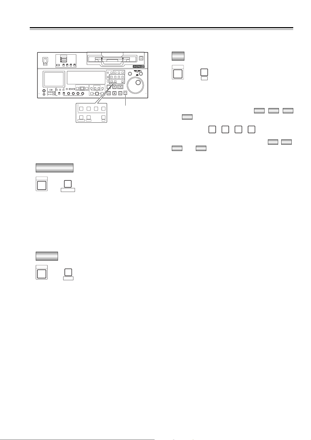
c SHIFT button
When the SHIFT button is pressed together with the
buttons shown below, other operations can be
performed.
This combination is used to set the time code or
user bit value.
Press the PLAYER button while holding down the
SHIFT button to stop the advance of the time code
or user bit, and change the value using the search
dial.
O For further details, refer to the “Time code/user
bit” section (page 62).
TC PRESET
+
SHIFT
PLAYER
TC PRESET
This combination is used to set the unit to the menu
mode.
When the RECORDER button is pressed while
holding down the SHIFT button, the setup menu
screen is displayed on the LCD monitor, and the
setup menu item number appears on the counter
display. (The setup menu screen is also displayed
on the TV monitor which has been connected to the
VIDEO OUT 3 connector or SDI OUT 3 connector.)
O For further details, refer to the “Setup (initial
settings)” section (page 34).
MENU
+
SHIFT
RECORDER
MENU
This combination is used to set the unit to the PF
(Programmable Function) mode.
When the SET button is pressed while holding down
the SHIFT button, the CH1, CH2, CH3 and CH4
INSERT buttons function as the , ,
and buttons.
The setup menu items registered in the , ,
and buttons are displayed on the LCD
monitor. (The setup menu screen is also displayed
on the TV monitor which has been connected to the
VIDEO OUT 3 connector or SDI OUT 3 connector.)
O For further details, refer to the “PF
(Programmable Function) functions” section
(page 33).
PF4PF3
PF2PF1
CH 1
PF 1
CH 2
PF 2
CH 3
PF 3
CH 4
PF 4
PF4
PF3PF2PF1
PF
+
SET
PF
SHIFT
15
Front panel
Parts and their functions
(continued)
ON
POWER
REMOTE
SUPER
REC INH
TCG
MODE
ON
OFF
DVCPRO 50
EJECT
SEARCH
TC
CUE
VIDEO
ASSEM
COUNTER
CH 1 CH 2 CH 3 CH 4
PF 1 PF 2 PF 3 PF 4
RESET
PLAYER
RECORDER
SET
TC PRESET
MENU
PF
STAND BY
EDIT
A OUT
OUTIN SET
A IN
PREROLL
AUTO EDIT
PREVIEW/
REVIEW
INPUT SELECTMETER
AUDIO MON SELAUDIO MIXHEADPHONES
AUDIO VOL SEL
VIDEO
CH 1
RMIX
1&2
CH1/3
PULL
CH2/4
REC CH1/3
CH1/3 CH2/4
REC CH2/4
3&4
L
CH 2 CH 3 CH 4
AUDIO
FULL/FINE
RECPLAY
REW FF
SHIFT
PULL
STOP
INSERT
PUSH
DVCPRO
DV
2
X
OFF
RECPBUNITY
VAR
ON
OFF
INT
EXT
TAPE
EE
XL/L/M-
cassette
SHTL
JOG
SLOW
c
CH 1 CH 2 CH 3 CH 4
PF 1 PF 2 PF 3 PF 4
PLAYER
RECORDER
SET
TC PRESET
MENU
PF
Page 16

16
Display panel
1 TV system displays
The selected TV system is displayed here.
It is possible to switch between the 525 interlace
and 625 interlace systems by setting setup menu
item No. 070 (TV SYSTEM).
: This lights when the 525 interlaced TV system
has been selected.
: This lights when the 625 interlaced TV system
is selected.
2 WIDE lamp
This lamp lights when 16:9 wide-screen information
is being recorded on a tape.
Recording of wide-screen information can be
selected on setup menu No. 645 (WIDE SELECT).
This lights lamps during tape playback when widescreen information has been recorded on the tape.
3 REMOTE lamp
This lights when the REMOTE button 3 (page 7)
has been set to the remote mode.
4 INPUT SELECT display area
The characters corresponding to the selected input
signals light. With all input signals except for analog
audio signals, the fact that no signals have been
selected is indicated by a flashing display.
Y PB PR :
Analog component video signals
(option)
CMPST :
Analog composite video signals
(option)
SDI :
Serial digital video signals
SDTI/1394 :
IEEE 1394 compressed digital signals
(option)
SG/SG 1/SG 2:
Internal reference signals
ANALOG :
Analog audio signals
AES/EBU :
Digital audio signals
USER SET :
Recording audio signal selection
SDI :
Serial digital audio signals
SDTI/1394 :
IEEE 1394 compressed digital signals
(option)
SG :
Internal reference signals
AUDIO
VIDEO
625
525
Parts and their functions
(continued)
5 lamp
This lamp lights when UMID information is present
on the input signal in E-E mode.
This lamp lights during tape playback when UMID
information has been recorded on the tape.
6 SCH lamp
This lamp lights when the SCH phase of the
external synchronized signal (REF VIDEO) is inside
the prescribed range.
At all other times, the lamp is off.
7=lamp
This lamp lights when a cassette tape is inserted
into the VTR.
In the standby OFF mode, this lamp is flashing.
8 SERVO lamp
This lamp lights when the drum servo or capstan
servo locks.
9 Channel condition lamps
These lamps light to indicate the error rate status.
(green 5 white 5 red)
Green:
This lights when the error rates for the video
and audio playback signals are both at
acceptable levels.
White :
This lights when the error rate for the video
or audio playback level has increased.
The playback picture and sound remain
unaffected even while this lamp is lit.
Red :
This lights when the error rate for the video
or audio playback level has increased to the
extent that correction or interpolation was
performed.
U
3 6 85741 92
CTL
ANALOG
AUDIO
U
AES/EBU
USER SET
SDI
SDTI/1394
SG
INH
SCH
DVCPRO
50
DVCAM
SERVO
EDIT REC
TC
UB
=
Y PB PR
VIDEO
CMPST
SDI
SDTI/1394
SG 1 2
REMOTEWIDE
625525
dB
0
-
4
-
8
-
12
-
16
-
20
-
25
-
30
-
Page 17

17
: EDIT, EDIT REC, REC and REC INH lamps
EDIT:
This lights when an editing mode has been
selected.
EDIT REC:
This lights when the edit recording mode has
been established.
REC:
This lights when the recording mode has been
established.
REC INH:
This lights in the recording inhibit status (when
the REC INH switch at the bottom front panel is
set to ON or the cassette is in the accidental
erasure prevention status).
In this status, recording and editing are not
possible.
Whether the REC INH lamp is to light or flash
when recording has been inhibited by the
accidental erasure prevention tab on the cassette
tape can be selected using setup menu No. 114
(REC INH LAMP).
;
Page 18

18
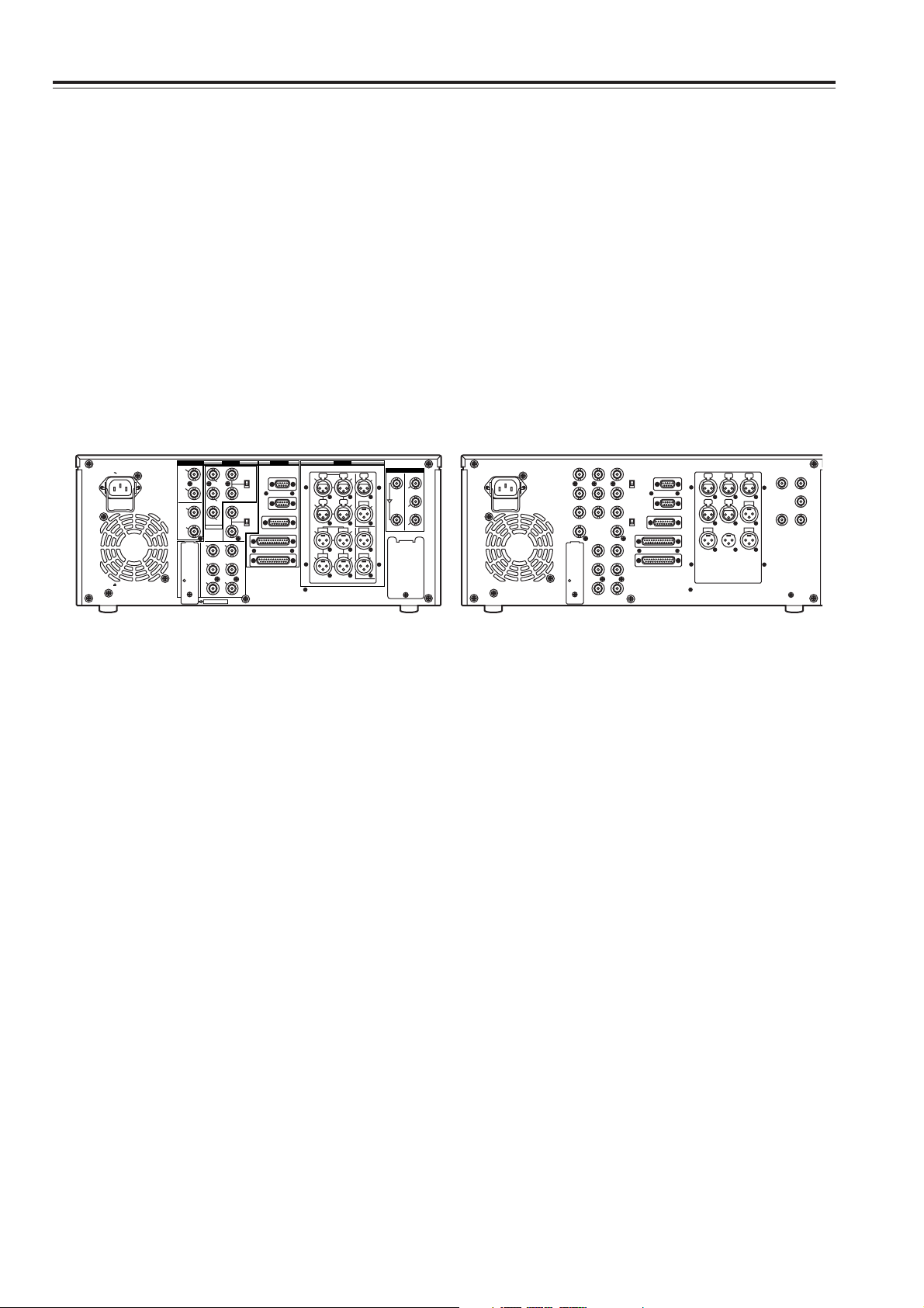
Rear panel
1 AC IN socket
Connect one end of the power cord supplied to this
socket and the other end to the power outlet.
2 DIGITAL AUDIO IN and OUT connectors
These are the input and output connectors for digital
audio signals that comply with the AES/EBU
standards.
<Note>
The digital audio signals which are to be input to
these connectors must be synchronized with the
video input signals. Otherwise, noise will be
generated in the audio output signals.
3 ANALOG COMPONENT VIDEO IN connectors
(optional)
The analog component video signals are input to
these connectors.
4 ANALOG COMPOSITE VIDEO IN connectors and
75 Ω termination switch (optional)
The analog composite video signals are input to
these connectors. A loop-through configuration is
featured for each pair of input connectors.
For termination at this VTR, set the termination
switch to ON.
5 REF VIDEO IN connectors and 75 Ω termination
switch
These are the input connectors of the reference
video signals.
Input a reference signal with color burst.
For termination at this VTR, set the termination
switch to ON.
<Note>
Video and audio output may be disturbed when the
reference video signal is not input, so it is
recommended that a system which inputs the
reference video signal be used.
Parts and their functions
(continued)
6 Remote control connectors
These connectors make it possible to use two of
these VTRs or to connect this VTR to an external
controller so that the VTR can be operated from an
external component.
Two remote control connectors are provided: one for
IN/OUT use and the other for OUT use only.
IN/OUT:
For connection with an external controller
For connection with deck-to-deck operations
OUT:
For connection with parallel run operations
For loop-through use
<Note>
If connection is to be made to the OUT connector for
deck-to-deck operations where this VTR will serve
as the recorder, which of the two connectors is to be
used can be selected using setup menu No. 212
(MASTER PORT).
7 ENCODER REMOTE connector
An external encoder remote controller is connected
to this connector when the video output signal
settings are to be adjusted from an external
component.
8 ANALOG AUDIO IN connectors
These are the analog audio input connectors.
9 TIME CODE IN connector
This connector is used to record an external time
code onto the tape.
: TIME CODE OUT connector
During playback, the playback time code is output
through this connector.
During recording, the time code generated by the
internal time code generator is output.
; SERIAL DIGITAL COMPONENT AUDIO and
VIDEO IN and OUT connectors
These are the input and output connectors for the
digital component audio and video signals that
comply with the ITU-R BT.656-4 standard.
Video signals containing superimposed information
can be output through the SDI OUT 3 connector.
Whether the superimposing is to be set ON or OFF
is selected using the SUPER switch 4 on the front
panel.
<Note>
The digital audio signals which are to be input to
these connectors must be synchronized with the
video input signals. Otherwise, noise will be
generated in the audio output signals.
PUSH PUSH
PUSH PUSH
PUSH
AC IN
SIGNAL
GND
AES/EBU
SDI
ANALOG
CH1/2
IN
Y
VIDEO
VIDEO
OUT
SERVICE ONLY
REMOTE IN/OUT
CH1 CH2AUDIO
IN
ENCODER REMOTE
RS-232C
PARALLEL
REMOTE OUT
IN
REF VIDEO
IN
ON
OFF
P
B
P
R
Y1
2
(WFM)
3
(SUPER)
P
B
P
R
OPTION
CH3/4
IN
CH1/2
OUT
CH3/4
OUT
REMOTE
75Ω
ON
OFF
75Ω
ANALOG
TC
IN
IN
ACTIVE
THROUGH
OUT
1
TC
OUT
MON
L
MON
R
CH4
CH3
CH1 CH2AUDIO
OUT
CH4
CH3
2
OPTION
3
(SUPER)
1 92 8 ;64 5 7 :3
Page 19

19
Rear panel
< Fan
This fan is used to cool down the VTR.
If, for any reason, the fan stops, “E-10” will appear
on the counter display.
= SIGNAL GND terminal
This is connected to the signal ground terminal on
the component connected to this VTR in order to
minimize noise. It is not a safety ground.
> ANALOG COMPONENT VIDEO OUT connectors
The analog component video signals are output
through these connectors.
? ANALOG COMPOSITE VIDEO OUT connectors
The analog composite video signals are output
through these connectors.
The waveform monitor (WFM) signal can be output
from the VIDEO OUT 2 connector.
It can be selected using setup menu No. 00 (WFM
SEL).
Video signals containing superimposed information
can be output through the VIDEO OUT 3 connector.
Whether the superimposing is to be set ON or OFF
is selected using the SUPER switch 4 on the front
panel.
@ RS-232C connector
A personal computer or other component can be
connected to this connector to operate the VTR.
Parts and their functions
(continued)
A PARALLEL REMOTE connector
This connector is used when the VTR is to be
operated by an external component.
B ANALOG AUDIO OUT connectors
The analog audio signals are output through these
connectors.
C MONITOR OUT connectors
During playback, the PCM audio signals
(CH1/CH2/CH3/CH4) or playback signals from the
CUE track are output through these connectors.
<Note>
Noise may appear on the CUE signal at the instant
recording is started.
D OPTION connector
Use of an digital video interface board (AJYAD955G, optional accessory) enables input/output
interfacing of the digital signals with the IEEE1394
standard.
Page 20
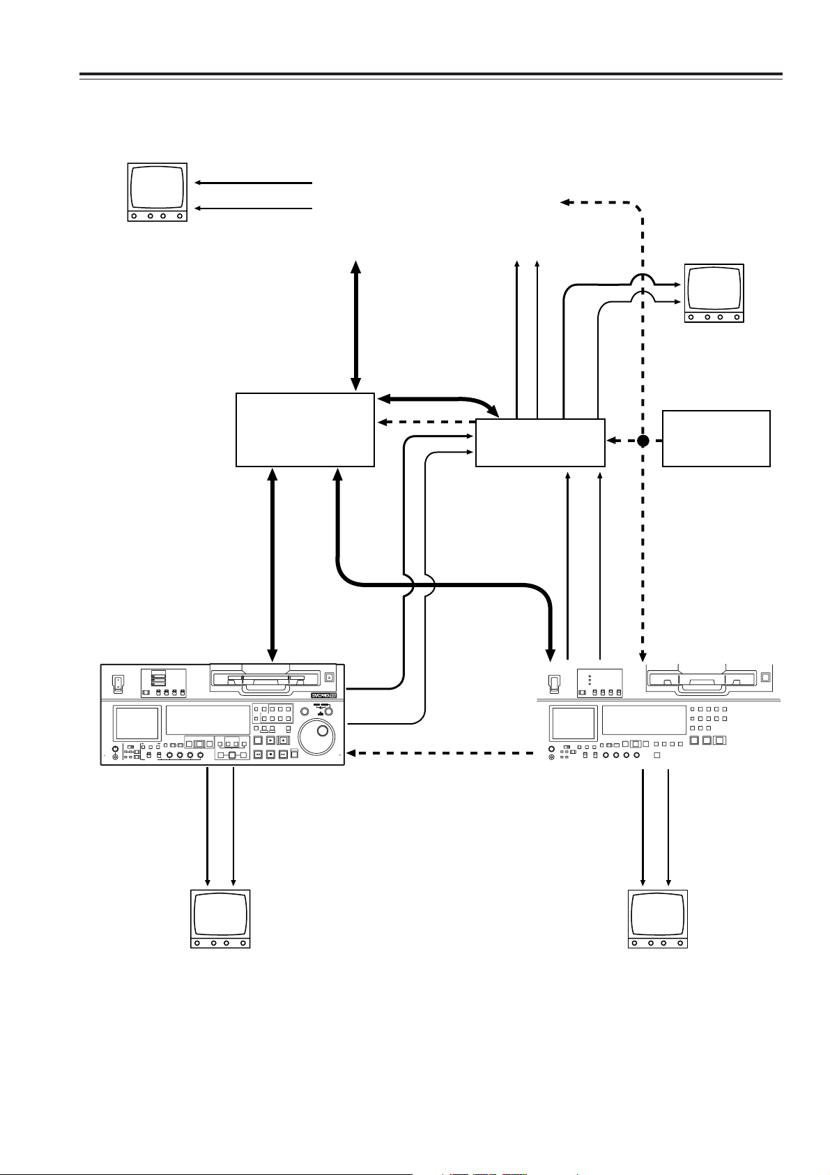
20
Source machine:
Set the REMOTE button 3 on the front panel to the remote mode (REMOTE lamp ON).
Recorder:
Set the REMOTE button 3 on the front panel to the local mode (REMOTE lamp OFF).
Connections
ANALOG
AES/EBU
CH1/2
AC IN
SIGNAL
GND
IN
CH3/4
IN
CH1/2
OUT
CH3/4
OUT
Y
P
B
P
R
OPTION
Y1
2
P
B
(WFM)
3
P
(SUPER)
R
SERVICE ONLY
VIDEO
VIDEO
IN
REF VIDEO
IN
OUT
REMOTE
REMOTE IN/OUT
ON
75Ω
OFF
REMOTE OUT
ENCODER REMOTE
ON
75Ω
OFF
RS-232C
PARALLEL
PUSH PUSH
CH1 CH2AUDIO
PUSH PUSH
CH3
CH1 CH2AUDIO
CH3
OUT
IN
ANALOG
SDI
IN
OUT
TC
PUSH
IN
1
ACTIVE
TC
THROUGH
CH4
OUT
2
3
(SUPER)
MON
L
OPTION
MON
CH4
R
Page 21
21
Connections with editing controller
Connections (continued)
ON
OFF
PULL
DVCPRO 50
POWER
2
X
DVCPRO
DV
SUPER
REC INH
TCG
MODE
REMOTE
ON
ON
INT
TAPE
OFF
OFF
EXT
EE
PREVIEW/
PREROLL
AUTO EDIT
INPUT SELECTMETER
REVIEW
FULL/FINE
VIDEO
AUDIO
AUDIO MON SELAUDIO MIXHEADPHONES
1&2
3&4
REC CH1/3
RMIX
L
CH 1
RECPBUNITY
AUDIO VOL SEL
CH 2 CH 3 CH 4
VAR
CH1/3
CH2/4
REC CH2/4
CH1/3 CH2/4
XL/L/M-
cassette
CUE
VIDEO
ASSEM
COUNTER
INSERT
CH 1 CH 2 CH 3 CH 4
RESET
PF 1 PF 2 PF 3 PF 4
PLAYER
RECORDER
STAND BY
TC PRESET
MENU
EDIT
RECPLAY
A OUT
A IN
REW FF
STOP
OUTIN SET
EJECT
SHTL
SLOW
TC
SEARCH
PUSH
JOG
SET
PF
SHIFT
PULL
Page 22
22
ON
POWER
REMOTE
SUPER
REC INH
TCG
MODE
ON
OFF
DVCPRO 50
EJECT
SEARCH
TC
CUE
VIDEO
ASSEM
COUNTER
CH 1 CH 2 CH 3 CH 4
PF 1 PF 2 PF 3 PF 4
RESET
PLAYER
RECORDER
SET
TC PRESET
MENU
PF
STAND BY
EDIT
A OUT
OUTIN SET
A IN
PREROLL
AUTO EDIT
PREVIEW/
REVIEW
INPUT SELECTMETER
AUDIO MON SELAUDIO MIXHEADPHONES
AUDIO VOL SEL
VIDEO
CH 1
RMIX
1&2
CH1/3
PULL
CH2/4
REC CH1/3
CH1/3 CH2/4
REC CH2/4
3&4
L
CH 2 CH 3 CH 4
AUDIO
FULL/FINE
RECPLAY
REW FF
SHIFT
PULL
STOP
INSERT
PUSH
DVCPRO
DV
2
X
OFF
RECPBUNITY
VAR
ON
OFF
INT
EXT
TAPE
EE
XL/L/M-
cassette
SHTL
JOG
SLOW
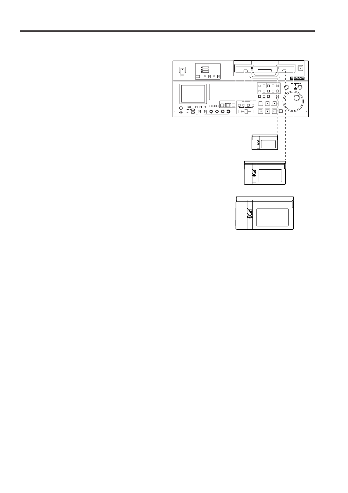
L cassette size
XL cassette size
Consumer-use DV and DVCAM cassettes
(Standard DV and DVCAM cassettes, mini DV and
DVCAM cassettes)
O Use a cassette adapter (AJ-CS455P) when a mini
DV or DVCAM cassette is to be used.
Note that inserting a mini DV or DVCAM cassette
without the use of a cassette adapter will cause
malfunctioning.
Also note that long-duration mini DV cassettes (80
minutes in the standard mode and 120 minutes in
the LP mode) cannot be used.
O It is not possible to play back tapes which have
been recorded in the LP mode.
O When editing material recorded on a consumer-use
DV or DVCAM cassette, first record the material on
a DVCPRO tape or other tape used by VTRs for
broadcast applications.
O The maximum transport speed of a mini DV or
DVCAM cassette tape is 32a.
O The images may be subject to disturbance during
the slow motion playback of consumer-use DV and
DVCAM cassette tapes.
O From the perspective of protecting consumer-use
DV and DVCAM cassette tapes, minimize the
number of times the tapes are cued up at the same
locations as much as possible.
O When consumer-use DV and DVCAM cassette
tapes are used, the maximum time for STILL TIMER
is set to 10 seconds.
It is recommended that tapes bearing the
Panasonic brand be used as the consumer-use DV
tapes.
M cassettes
Tapes enabling recording and playback for up to 33
minutes at the 50 Mbps rate and for up to 66 minutes
at the 25 Mbps rate.
(AJ-P66MP)
L cassettes
Tapes enabling recording and playback for up to 92
minutes at the 50 Mbps rate and for up to 184 minutes
at the 25 Mbps rate.
(AJ-P126LP, AJ-5P92LP)
O Use AJ-5P92LP tapes which have been recorded
using the DVCPRO (25M) format in a VTR that
supports 184 minutes of DVCPRO (25M) format
recording and playback.
XL cassettes
Tapes enabling recording and playback for up to 126
minutes at the 50 Mbps rate and for up to 252 minutes
at the 25 Mbps rate.
(AJ-5P126XG)
M cassette size
Tapes
Align the center of the cassette with the center of the
insertion slot, and press it in gently.
The cassette tape will load automatically.
Page 23

23
Jog mode
Jog/Shuttle
1
Press the search dial so that it remains pressed in.
Check that the JOG lamp has lit.
Shuttle mode
1
Press the search dial so that it is released from the
pressed-in position.
The SHTL lamp lights, and the shuttle mode is
established.
O Immediately after the power is turned on, turn the
search dial and leave it at the center position.
3
To transfer the VTR from the jog mode to another
mode, press the button that corresponds to the
mode concerned.
2
Turn the search dial.
The dial’s click-stops are released, and the tape is
played back at the speed (–1a to +1a )
corresponding to the speed at which the dial is
turned.
The maximum speed can be switched using setup
menu No. 323 (JOG FWD MAX) and No. 324 (JOG
REV MAX) settings.
However, noise will occur at all speeds other than
–0.43a to +0.43a.
When the dial is no longer turned, the still picture
mode is established.
3
Turn the search dial.
O When the SHTL lamp among the JOG, SHTL
and SLOW lamps is lit, the playback picture
speed changes from 0 up to ±32a depending on
the dial position.
This speed can be switched to ±8.4a, ±16a or
±32a using setup menu No. 101 (SHTL MAX).
The dial has a click-stop at the center position
where the still picture mode is established.
O When the SLOW lamp among the JOG, SHTL
and SLOW lamps is lit, the playback picture
speed changes from –4.1 up to +4.1a depending
on the dial position.
The maximum speed can be switched using
setup menu No. 320 (VAR FWD MAX) and No.
321 (VAR REV MAX) settings. However, noise
will occur at all speeds other than –0.43a to
+0.43a, +0.5a and +0.75a.
The dial has a click-stop at the center position
where the still picture mode is established.
4
To transfer the VTR from the shuttle mode to
another mode, press the STOP button or other
button.
2
Press the SHTL/SLOW button and switch to SHTL
or SLOW.
<Note>
The direct search mode in which the VTR is
transferred to the shuttle mode or jog mode by turning
the search dial is set at the factory.
By selecting KEY as the setup menu No. 100
(SEARCH ENA) setting, the VTR can be set to the
mode in which it will not be transferred to the search
mode unless the search button is pressed.
<Notes>
O It is possible to listen to playback audio in the –10 to
+10 speed range from the audio monitor output.
(PCM must be selected for the setup menu No. 721
(MONI CH SELECT) setting.)
O The audio playback sound heard in the search
mode contains noise.
Page 24

24
Manual editing
1
Select the editing mode.
ASSEMBLE:
Assemble (frame-to-frame continuity) editing is
performed in this mode.
INSERT:
Insert editing is performed in this mode.
2
Select the channels to be edited.
For insert editing, press the buttons corresponding
to the channels to be edited so that their lamps
light.
3
Press the PLAY button.
4
While monitoring the TV monitor, search the
position (IN point) where the editing is to be started,
and press the PLAY and EDIT buttons together at
this position.
5
Similarly, while monitoring the TV monitor, search
the position (OUT point) where the editing is to be
terminated, and press the PLAY or STOP button at
this position.The unit will change to STOP or PLAY
mode and editing will stop.
Preroll
1
Press the PREROLL button.
The VTR now performs the preroll operation.
O If the edit IN point has been registered, the tape
is rewound from the edit IN point for the period of
time which was set by setup menu No. 000 (PROLL TIME), and it then stops.
O If the edit IN point has not been registered, the
tape is rewound from the position where the
button was pressed for the period of time which
was set by setup menu item No.000 (P-ROLL
TIME), and it then stops.
<Notes>
O The time code or CTL must be continuously
recorded on the tape between the edit IN point and
preroll point.
O When the IN point has not been registered, it is
possible to select whether to register the IN point
and proceed with the preroll or proceed with the
preroll without registering the IN point using setup
menu No. 313 (AUTO ENTRY).
Page 25
25
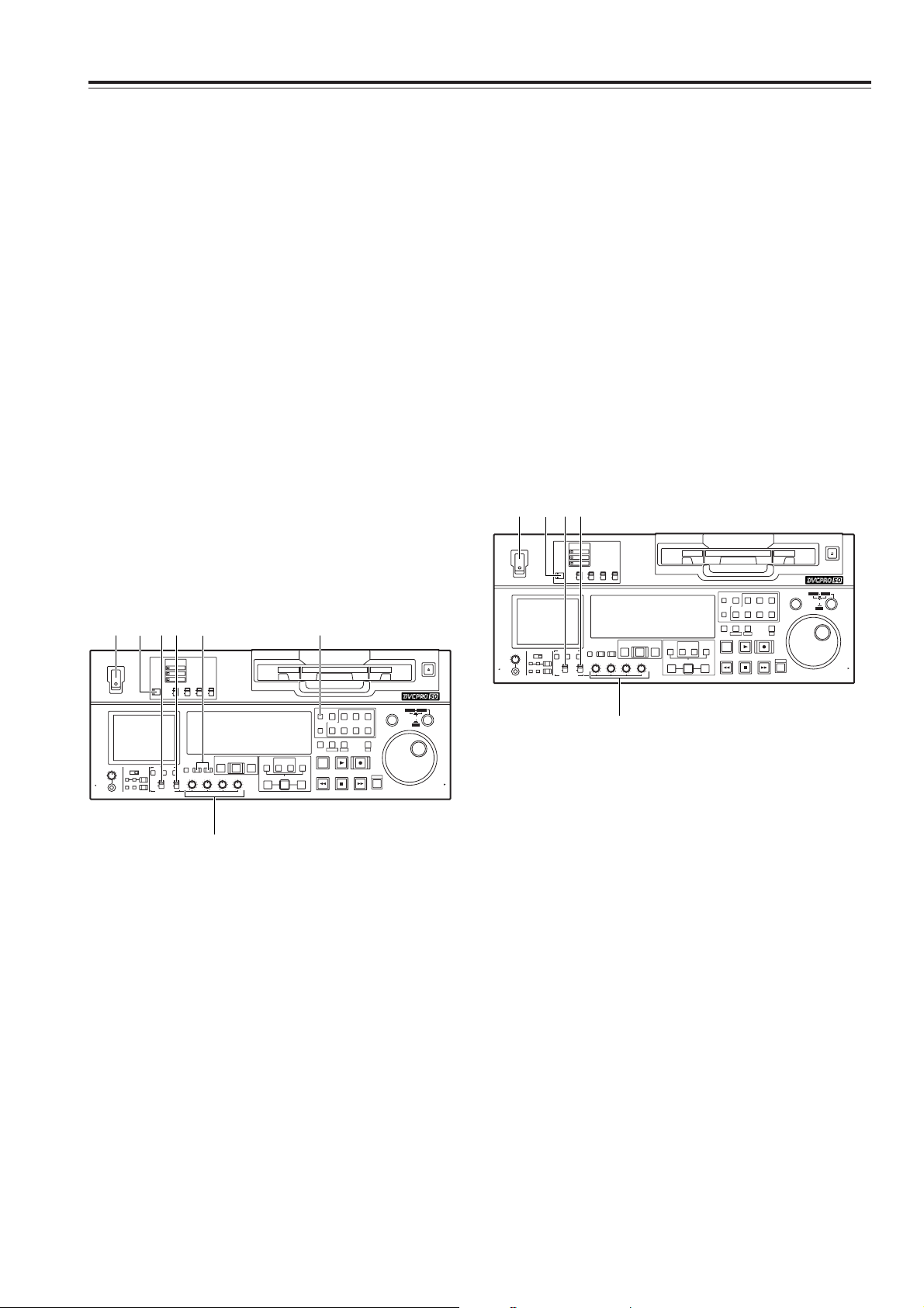
Automatic editing (deck-to-deck)
1
Set the POWER switch to ON.
2
Use the INPUT SELECT buttons to select the video
and audio input signals.
3
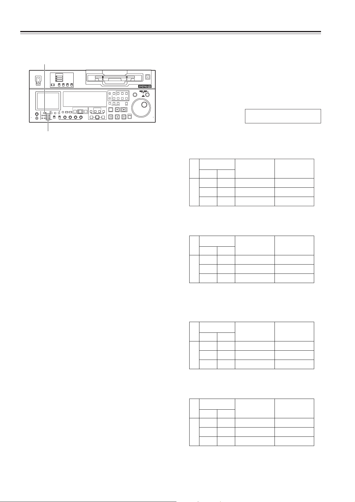
Switch the time counter display to TC, CTL or UB.
5
If the recording levels are to be adjusted using the
level controls, set the AUDIO VOL SEL
(UNITY/VAR) switch to the VAR position.
If the recording levels are to be fixed, set the switch
to the UNITY position.
6
Set the REMOTE button to the local mode
(REMOTE lamp OFF).
Switch settings and adjustments
When using the AJ-SD965 as the recorder
1
Set the POWER switch to ON.
3
If the playback levels are to be adjusted using the
level controls, set the AUDIO VOL SEL
(UNITY/VAR) switch to the VAR position.
If the playback levels are to be fixed, set the switch
to the UNITY position.
4
Set the REMOTE button to the remote mode
(REMOTE lamp ON).
When using the AJ-SD965 as the player
4
Set the AUDIO VOL SEL (REC/PB) switch to the
REC position.
2
Set the AUDIO VOL SEL (REC/PB) switch to the
PB position.
Audio level control knobs
Audio level control knobs
ON
POWER
REMOTE
SUPER
REC INH
TCG
MODE
ON
OFF
DVCPRO 50
EJECT
SEARCH
TC
CUE
VIDEO
ASSEM
COUNTER
CH 1 CH 2 CH 3 CH 4
PF 1 PF 2 PF 3 PF 4
RESET
PLAYER
RECORDER
SET
TC PRESET
MENU
PF
STAND BY
EDIT
A OUT
OUTIN SET
A IN
PREROLL
AUTO EDIT
PREVIEW/
REVIEW
INPUT SELECTMETER
AUDIO MON SELAUDIO MIXHEADPHONES
AUDIO VOL SEL
VIDEO
CH 1
RMIX
1&2
CH1/3
PULL
CH2/4
REC CH1/3
CH1/3 CH2/4
REC CH2/4
3&4
L
CH 2 CH 3 CH 4
AUDIO
FULL/FINE
RECPLAY
REW FF
SHIFT
PULL
STOP
INSERT
PUSH
DVCPRO
DV
2
X
OFF
RECPBUNITY
VAR
ON
OFF
INT
EXT
TAPE
EE
XL/L/M-
cassette
SHTL
JOG
SLOW
1 3546 2
ON
POWER
REMOTE
SUPER
REC INH
TCG
MODE
ON
OFF
DVCPRO 50
EJECT
SEARCH
TC
CUE
VIDEO
ASSEM
COUNTER
CH 1 CH 2 CH 3 CH 4
PF 1 PF 2 PF 3 PF 4
RESET
PLAYER
RECORDER
SET
TC PRESET
MENU
PF
STAND BY
EDIT
A OUT
OUTIN SET
A IN
PREROLL
AUTO EDIT
PREVIEW/
REVIEW
INPUT SELECTMETER
AUDIO MON SELAUDIO MIXHEADPHONES
AUDIO VOL SEL
VIDEO
CH 1
RMIX
1&2
CH1/3
PULL
CH2/4
REC CH1/3
CH1/3 CH2/4
REC CH2/4
3&4
L
CH 2 CH 3 CH 4
AUDIO
FULL/FINE
RECPLAY
REW FF
SHIFT
PULL
STOP
INSERT
PUSH
DVCPRO
DV
2
X
OFF
RECPBUNITY
VAR
ON
OFF
INT
EXT
TAPE
EE
XL/L/M-
cassette
SHTL
JOG
SLOW
1 324
Page 26
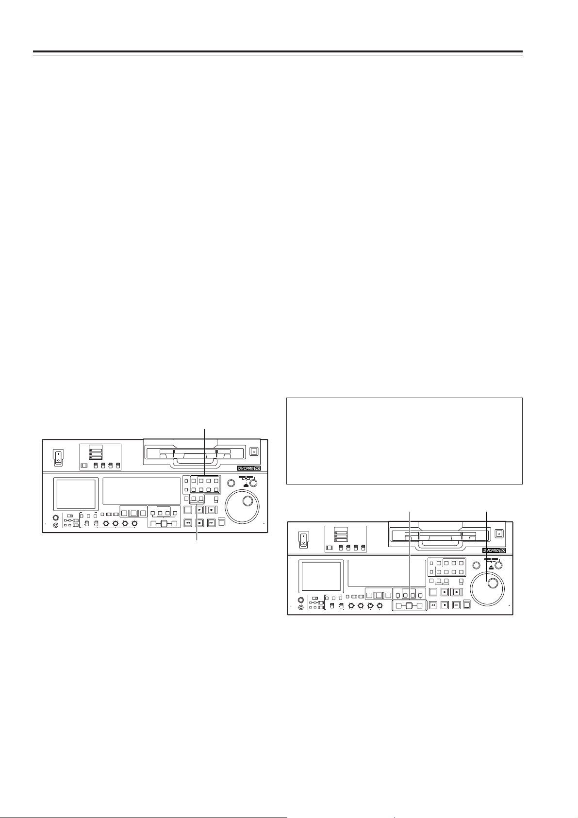
26
Automatic editing
(deck-to-deck) (continued)
1
Select the editing mode.
For assemble editing, press the ASSEM button.
For insert editing, press the INSERT button.
ASSEM:
This sets the unit to assemble (frame-to-frame
continuity) editing mode.
INSERT:
This sets the unit to insert editing mode.
2
Select the channels to be edited.
With assemble editing, the ASSEM lamp lights.
With insert editing, press the buttons corresponding
to the channels to be edited so that their lamps
light.
3
Select the VTR to be operated.
(Settings for editing using two VTRs)
Press the PLAYER or RECORDER button to select
the VTR which is to be operated.
PLAYER:
Press this button if the player VTR is to be
operated to register the edit points.
RECORDER:
Press this button if the recorder VTR (this unit) is
to be operated to register the edit points.
Selecting the editing mode
1
Locate the edit IN point by performing the jog or
shuttle operation.
Set the tape to the still picture mode at the desired
position.
For a detailed description of the jog and shuttle
operations, refer to page 23.
2
Press the SET button while holding down the IN
button.
The edit IN point is now registered.
The edit IN point value appears on the display
panel.
3
Locate the edit OUT point by performing the jog or
shuttle operation.
Set the tape to the still picture mode at the desired
position.
Registering the edit points
Match frame processing function
When two VTRs are used to perform the editing
operations, there will be a total of 4 edit points: the
IN and OUT points for the player and those for the
recorder. However, the last point is automatically
calculated so only three of the edit points need to be
registered.
4
Press the SET button while holding down the OUT
button.
The edit OUT point is now registered.
The edit OUT point value appears on the display
panel.
ON
POWER
REMOTE
SUPER
REC INH
TCG
MODE
ON
OFF
DVCPRO 50
EJECT
SEARCH
TC
CUE
VIDEO
ASSEM
COUNTER
CH 1 CH 2 CH 3 CH 4
PF 1 PF 2 PF 3 PF 4
RESET
PLAYER
RECORDER
SET
TC PRESET
MENU
PF
STAND BY
EDIT
A OUT
OUTIN SET
A IN
PREROLL
AUTO EDIT
PREVIEW/
REVIEW
INPUT SELECTMETER
AUDIO MON SELAUDIO MIXHEADPHONES
AUDIO VOL SEL
VIDEO
CH 1
RMIX
1&2
CH1/3
PULL
CH2/4
REC CH1/3
CH1/3 CH2/4
REC CH2/4
3&4
L
CH 2 CH 3 CH 4
AUDIO
FULL/FINE
RECPLAY
REW FF
SHIFT
PULL
STOP
INSERT
PUSH
DVCPRO
DV
2
X
OFF
RECPBUNITY
VAR
ON
OFF
INT
EXT
TAPE
EE
XL/L/M-
cassette
SHTL
JOG
SLOW
1•2
3
ON
POWER
REMOTE
SUPER
REC INH
TCG
MODE
ON
OFF
DVCPRO 50
EJECT
SEARCH
TC
CUE
VIDEO
ASSEM
COUNTER
CH 1 CH 2 CH 3 CH 4
PF 1 PF 2 PF 3 PF 4
RESET
PLAYER
RECORDER
SET
TC PRESET
MENU
PF
STAND BY
EDIT
A OUT
OUTIN SET
A IN
PREROLL
AUTO EDIT
PREVIEW/
REVIEW
INPUT SELECTMETER
AUDIO MON SELAUDIO MIXHEADPHONES
AUDIO VOL SEL
VIDEO
CH 1
RMIX
1&2
CH1/3
PULL
CH2/4
REC CH1/3
CH1/3 CH2/4
REC CH2/4
3&4
L
CH 2 CH 3 CH 4
AUDIO
FULL/FINE
RECPLAY
REW FF
SHIFT
PULL
STOP
INSERT
PUSH
DVCPRO
DV
2
X
OFF
RECPBUNITY
VAR
ON
OFF
INT
EXT
TAPE
EE
XL/L/M-
cassette
SHTL
JOG
SLOW
2•4 1•3
Page 27

27
Automatic editing
(deck-to-deck) (continued)
1
Press the IN (or OUT) button to check the edit
point. The value of the registered edit point appears
on the display panel.
2
While holding down the IN (or OUT) button, press
the PREROLL button and check the picture at the
edit point.
The tape is cued up to the edit IN (or OUT) point,
and a still picture of the point appears.
O If STOP has been selected as the setup menu
No. 315 (AFTER CUE-UP) setting and if the
MODE switch has been set to EE, the VTR is set
to the E-E mode.
3
By holding down the IN and OUT buttons at the
same time, check the editing duration.
The duration appears on the display panel.
How to calculate the duration
O When two edit points have been set:
Duration between the two points
O When only one edit point has been set:
Duration between the data which has been set
and the current address
O When no edit points have been set:
Duration of the previously edited section
4
After the edit points have been registered, press the
PREVIEW button.
Regular preview is now conducted.
<Notes>
O If the edit IN point has not been registered, the
position where the PREVIEW button was
pressed is registered as the edit IN point.
O To stop the preview at any time, press the STOP
button.
O When the PREVIEW button is pressed again
after the IN point during the course of a preview,
the preview will start again from the beginning.
O When the edit OUT point is reached, the tape
stops automatically.
Checking and previewing edit points
ON
POWER
REMOTE
SUPER
REC INH
TCG
MODE
ON
OFF
DVCPRO 50
EJECT
SEARCH
TC
CUE
VIDEO
ASSEM
COUNTER
CH 1 CH 2 CH 3 CH 4
PF 1 PF 2 PF 3 PF 4
RESET
PLAYER
RECORDER
SET
TC PRESET
MENU
PF
STAND BY
EDIT
A OUT
OUTIN SET
A IN
PREROLL
AUTO EDIT
PREVIEW/
REVIEW
INPUT SELECTMETER
AUDIO MON SELAUDIO MIXHEADPHONES
AUDIO VOL SEL
VIDEO
CH 1
RMIX
1&2
CH1/3
PULL
CH2/4
REC CH1/3
CH1/3 CH2/4
REC CH2/4
3&4
L
CH 2 CH 3 CH 4
AUDIO
FULL/FINE
RECPLAY
REW FF
SHIFT
PULL
STOP
INSERT
PUSH
DVCPRO
DV
2
X
OFF
RECPBUNITY
VAR
ON
OFF
INT
EXT
TAPE
EE
XL/L/M-
cassette
SHTL
JOG
SLOW
4 1•32
Page 28

28
Automatic editing
(deck-to-deck) (continued)
1
Re-registering an edit point
Locate the new edit point by performing the jog or
shuttle operation, and press the IN (or OUT) button
and SET button at the same time to re-register the
edit point.
2
Modifying an edit point in 1-frame increments
(trimming function)
Press the TRIM button while holding down the IN
(or OUT) button. Each time the + button is pressed,
the point is moved ahead by one frame.
Conversely, each time the – button is pressed, the
point is moved back by one frame.
3
Resetting edit points
O Resetting both an edit IN point and OUT point
Press the RESET button.
(This takes effect only in the CTL mode.)
O Resetting either an edit IN point or OUT point
Press the RESET button while holding down the
IN (or OUT) button.
<Notes>
O An edit OUT point can be reset even while
editing is in progress.
O In the eject mode, the IN and OUT points are
automatically reset.
Modifying edit points
ON
POWER
REMOTE
SUPER
REC INH
TCG
MODE
ON
OFF
DVCPRO 50
EJECT
SEARCH
TC
CUE
VIDEO
ASSEM
COUNTER
CH 1 CH 2 CH 3 CH 4
PF 1 PF 2 PF 3 PF 4
RESET
PLAYER
RECORDER
SET
TC PRESET
MENU
PF
STAND BY
EDIT
A OUT
OUTIN SET
A IN
PREROLL
AUTO EDIT
PREVIEW/
REVIEW
INPUT SELECTMETER
AUDIO MON SELAUDIO MIXHEADPHONES
AUDIO VOL SEL
VIDEO
CH 1
RMIX
1&2
CH1/3
PULL
CH2/4
REC CH1/3
CH1/3 CH2/4
REC CH2/4
3&4
L
CH 2 CH 3 CH 4
AUDIO
FULL/FINE
RECPLAY
REW FF
SHIFT
PULL
STOP
INSERT
PUSH
DVCPRO
DV
2
X
OFF
RECPBUNITY
VAR
ON
OFF
INT
EXT
TAPE
EE
XL/L/M-
cassette
SHTL
JOG
SLOW
12 3
Page 29

29
2
Upon completion of the editing, press the REVIEW
button.
Review is then started by the recorder side.
O To stop the review at any time, press the STOP
button.
O When the edit OUT point is reached, the tape is
post-rolled, after which it stops.
1
Press the AUTO EDIT button.
Automatic editing is now executed.
O To suspend editing at any time, press the STOP
button.
O When the edit OUT point is reached, the tape is
post-rolled, after which it stops.
Post-rolling
With assemble editing, editing continues for about 2
seconds after the edit OUT point is passed, the
tape is then returned to the OUT point, after which it
stops.
With insert editing, the PLAY mode is established
after the edit OUT point has been passed, the tape
is then returned to the OUT point, after which it
stops.
The post-roll time can be set using setup menu No.
325 (POSTROLL TM).
Retry function
Even when the STOP button has been pressed to
suspend editing, editing can be repeated from the
beginning simply by pressing the AUTO EDIT
button again.
Auto tag function (recorder side)
If, upon completion of editing, the next edit point
has not yet been registered, the previous edit OUT
point is registered as the IN point and editing is
executed when the AUTO EDIT button is pressed.
To release the auto tag mode, press one of the
transport system buttons (such as the PLAY
button).
Registering an OUT point while editing is in
progress
If the SET button is pressed while the OUT button
is being held down when automatic editing is in
progress, the position corresponding to when the
button was pressed is registered as the OUT point
and the editing operation is exited.
Even if the AUTO EDIT button is pressed, the OUT
point is registered and editing is exited in the same
way.
<Note>
The registered points are automatically cleared
after editing has been executed. However, the
previous edit points can be recalled by pressing the
TRIM+ (or TRIM–) button and SET button at the
same time.
Executing and reviewing automatic editing
Automatic editing
(deck-to-deck) (continued)
ON
POWER
REMOTE
SUPER
REC INH
TCG
MODE
ON
OFF
DVCPRO 50
EJECT
SEARCH
TC
CUE
VIDEO
ASSEM
COUNTER
CH 1 CH 2 CH 3 CH 4
PF 1 PF 2 PF 3 PF 4
RESET
PLAYER
RECORDER
SET
TC PRESET
MENU
PF
STAND BY
EDIT
A OUT
OUTIN SET
A IN
PREROLL
AUTO EDIT
PREVIEW/
REVIEW
INPUT SELECTMETER
AUDIO MON SELAUDIO MIXHEADPHONES
AUDIO VOL SEL
VIDEO
CH 1
RMIX
1&2
CH1/3
PULL
CH2/4
REC CH1/3
CH1/3 CH2/4
REC CH2/4
3&4
L
CH 2 CH 3 CH 4
AUDIO
FULL/FINE
RECPLAY
REW FF
SHIFT
PULL
STOP
INSERT
PUSH
DVCPRO
DV
2
X
OFF
RECPBUNITY
VAR
ON
OFF
INT
EXT
TAPE
EE
XL/L/M-
cassette
SHTL
JOG
SLOW
12
Page 30

30
$ Displaying the audio split edit points
The edit points appear on the display panel.
Video IN point:
Press the IN button.
Video OUT point:
Press the OUT button.
Audio IN point:
Press the A IN button.
Audio OUT point:
Press the A OUT button.
<Note>
If the editing mode is changed to assemble editing
after the audio edit points have been registered, the
audio edit points will be cleared.
$ Cueing the tape up to the edit points
Cue-up to video IN point:
Press the PREROLL button while holding down
the IN button.
Cue-up to video OUT point:
Press the PREROLL button while holding down
the OUT button.
Cue-up to audio IN point:
Press the PREROLL button while holding down
the A IN button.
Cue-up to audio OUT point:
Press the PREROLL button while holding down
the A OUT button.
The video edit points and audio edit points can be
registered independently, and editing can be executed
with the video point offset from the audio points.
Audio edit points cannot be registered when the
assemble editing mode has been selected.
After registering the edit points, proceed with the same
operations as for insert editing.
$ Registering the edit points
Video IN point:
Press the SET button while holding down the IN
button.
Video OUT point:
Press the SET button while holding down the
OUT button.
Audio IN point:
Press the SET button while holding down the A
IN button.
Audio OUT point:
Press the SET button while holding down the A
OUT button.
$ Clearing the edit points
Video IN point:
Press the RESET button while holding down the
IN button.
Video OUT point:
Press the RESET button while holding down the
OUT button.
Audio IN point:
Press the RESET button while holding down the
A IN button.
Audio OUT point:
Press the RESET button while holding down the
A OUT button.
$ Modifying edit points
Video IN point:
Press the TRIM+ button or TRIM– button while
holding down the IN button.
Video OUT point:
Press the TRIM+ button or TRIM– button while
holding down the OUT button.
Audio IN point:
Press the TRIM+ button or TRIM– button while
holding down the A IN button.
Audio OUT point:
Press the TRIM+ button or TRIM– button while
holding down the A OUT button.
Audio split editing
A IN button A OUT button
ON
POWER
REMOTE
SUPER
REC INH
TCG
MODE
ON
OFF
DVCPRO 50
EJECT
SEARCH
TC
CUE
VIDEO
ASSEM
COUNTER
CH 1 CH 2 CH 3 CH 4
PF 1 PF 2 PF 3 PF 4
RESET
PLAYER
RECORDER
SET
TC PRESET
MENU
PF
STAND BY
EDIT
A OUT
OUTIN SET
A IN
PREROLL
AUTO EDIT
PREVIEW/
REVIEW
INPUT SELECTMETER
AUDIO MON SELAUDIO MIXHEADPHONES
AUDIO VOL SEL
VIDEO
CH 1
RMIX
1&2
CH1/3
PULL
CH2/4
REC CH1/3
CH1/3 CH2/4
REC CH2/4
3&4
L
CH 2 CH 3 CH 4
AUDIO
FULL/FINE
RECPLAY
REW FF
SHIFT
PULL
STOP
INSERT
PUSH
DVCPRO
DV
2
X
OFF
RECPBUNITY
VAR
ON
OFF
INT
EXT
TAPE
EE
XL/L/M-
cassette
SHTL
JOG
SLOW
Page 31

31
Audio split editing
(continued)
$ Duration display
The duration can be indicated on the display panel
only.
Between the video IN and OUT points:
Press the IN button and OUT button at the same
time.
Between the audio IN and OUT points:
Press the A IN button and A OUT button at the
same time.
Match frame processing system
When two VTRs are used to perform the audio split
editing operations, there will be a total of 8 edit
points: the video IN and OUT points for the player,
the video IN and OUT points for the recorder, the
audio IN and OUT points for the player, and the
audio IN and OUT points for the recorder.
When five of the eight edit points are registered, the
remaining three points are automatically calculated
so only five of the edit points need to be registered.
$ When a VTR not equipped with the split
editing function is used as the player
When a VTR that cannot set the video and audio
edit points independently is used as the player, split
editing is still possible by setting the audio IN point
and OUT point in the recorder and setting the data
of three points as the video edit points.
<Note>
If, during audio split editing, the video OUT point (or
audio OUT point) only is registered without the
audio OUT (or video OUT point) having been
registered and automatic editing is then executed,
either the audio OUT point (or video OUT point) will
be registered or editing will continue until the STOP
button is pressed to suspend the editing operation.
Page 32

32
4
After selecting VTR used as the player by pressing
PLAYER button, set the initial speed by the search
dial while pressing SET button.
5
Simultaneously pressing both SET button and
PREVIEW/REVIEW button results in automatic
prerolling for the both VTRs (player and recorder),
then the player VTR is operated at the set initial
speed up to the IN point.
6
After passing the IN point, turn the search dial to
memorize the playback speed of the VTR used as
the player.
7
When the tape has passed the OUT point set by
recorder, the memory of the playback speed will
terminate.
8
When AUTO EDIT button is pressed, variable
memory editing is executed.
Once editing has been executed, the memorized
speed will be cleared. The initial speed will not be
cleared however.
9
The result of editing can be checked by pressing
PREVIEW/REVIEW button.
<Notes>
O The content stored in the memory will be cleared in
a mode other than the variable memory mode.
Also, the memory will be cleared when the power
switch is turned OFF.
O Phase adjustment is not made during playback to
the IN point of variable memory editing.
Therefore, depending on the VTR used as the
player and its speed setting, no guarantees are
made for the accuracy of the IN point.
O When variable memory editing is to be performed,
keep the speed set to within the speed range for
variable speed playback which can be guarantied by
the VTR used as the player.
Using the unit as a controller (deck-to-deck editing
mode recorder) to control the playback speed of the
VTR used as the player, editing can be performed in
speed variable mode.
$ Selecting the variable memory mode
When deck-to-deck editing (either the RECORDER
or PLAYER lamp lights) is to be performed, set the
initial speed (–1.0 to +2.0) by turning the search dial
with the SET button held down to transfer the unit to
variable memory mode.
$ Releasing variable memory mode
Press the RESET button while holding down the
SET button to release the unit from variable memory
mode.
The unit will also be released from this mode when
deck-to-deck editing operations are completed.
Variable memory editing operation
procedure
Variable memory editing operation can be performed
according to the following procedure.
Variable memory editing
1
Select the edit mode by pressing ASSEM button or
desired INSERT buttons.
2
Select VTR to be operated by pressing
RECORDER or PLAYER button.
3
Register IN/OUT point by using SET button and
IN/OUT buttons.
The OUT point of VTR used as the player cannot
be registered.
ON
POWER
REMOTE
SUPER
REC INH
TCG
MODE
ON
OFF
DVCPRO 50
EJECT
SEARCH
TC
CUE
VIDEO
ASSEM
COUNTER
CH 1 CH 2 CH 3 CH 4
PF 1 PF 2 PF 3 PF 4
RESET
PLAYER
RECORDER
SET
TC PRESET
MENU
PF
STAND BY
EDIT
A OUT
OUTIN SET
A IN
PREROLL
AUTO EDIT
PREVIEW/
REVIEW
INPUT SELECTMETER
AUDIO MON SELAUDIO MIXHEADPHONES
AUDIO VOL SEL
VIDEO
CH 1
RMIX
1&2
CH1/3
PULL
CH2/4
REC CH1/3
CH1/3 CH2/4
REC CH2/4
3&4
L
CH 2 CH 3 CH 4
AUDIO
FULL/FINE
RECPLAY
REW FF
SHIFT
PULL
STOP
INSERT
PUSH
DVCPRO
DV
2
X
OFF
RECPBUNITY
VAR
ON
OFF
INT
EXT
TAPE
EE
XL/L/M-
cassette
SHTL
JOG
SLOW
1
3 2
ON
POWER
REMOTE
SUPER
REC INH
TCG
MODE
ON
OFF
DVCPRO 50
EJECT
SEARCH
TC
CUE
VIDEO
ASSEM
COUNTER
CH 1 CH 2 CH 3 CH 4
PF 1 PF 2 PF 3 PF 4
RESET
PLAYER
RECORDER
SET
TC PRESET
MENU
PF
STAND BY
EDIT
A OUT
OUTIN SET
A IN
PREROLL
AUTO EDIT
PREVIEW/
REVIEW
INPUT SELECTMETER
AUDIO MON SELAUDIO MIXHEADPHONES
AUDIO VOL SEL
VIDEO
CH 1
RMIX
1&2
CH1/3
PULL
CH2/4
REC CH1/3
CH1/3 CH2/4
REC CH2/4
3&4
L
CH 2 CH 3 CH 4
AUDIO
FULL/FINE
RECPLAY
REW FF
SHIFT
PULL
STOP
INSERT
PUSH
DVCPRO
DV
2
X
OFF
RECPBUNITY
VAR
ON
OFF
INT
EXT
TAPE
EE
XL/L/M-
cassette
SHTL
JOG
SLOW
8
9 5
4
4
Page 33

33
PF (Programmable Function) functions
1
Press (SHIFT + RECORDER).
The setup menu screen appears on the LCD
monitor, and the setup menu item number appears
on the counter display.
O The setup menu screen is also displayed on the
TV monitor which has been connected to the
VIDEO OUT 3 connector or SDI OUT 3
connector.
MENU
4
Turn the search dial to move the cursor (2) to the
item to be registered.
5
Press the STOP button.
The display screen returns to the status in step 2,
and the registered item is displayed at the position
of the specified PF button.
7
After the item(s) has (have) been registered, press
the SET button.
The registered item(s) is (are) stored in the
memory, and the regular screen is restored.
6
To register the next item in the next PF button,
repeat steps 2 to 5.
Four most frequently used setup items can be
registered in the four PF buttons.
Registering setup items in the PF
buttons
Page 34

34
4
Upon completion of the setting, release the search
button.
The item number now flashes.
O When the search dial is in the SHTL mode, the
item will move unless the dial is set to the center
position.
5
When other items are to be changed, repeat steps
2 to 4.
6
Press the SET button.
The changes are stored in the memory.
To disregard the new settings and restore the
old settings instead, press the RECORDER
button.
O To return the setup contents to the factory
settings (initial settings), press the RESET button
while the menu is displayed. The following
message is displayed.
If the PLAY button is now pressed, the factory
settings are reinstated.
SETUP-MENU INIT SET
YES<PLAY>/NO<STOP>
Setup (initial settings)
1
Press the (SHIFT+RECORDER).
The setup menu screen appears on the LCD
monitor, and the setup menu item number appears
on the counter display.
Each time the FF button is pressed (for about 1.5
seconds), the item number and item name are
selected and displayed alternately.
(If a setup was performed previously, the screen on
which the last change was made is displayed.)
O The setup menu screen is also displayed on the
TV monitor which has been connected to the
VIDEO OUT 3 connector or SDI OUT 3
connector.
MENU
3
At the position where the change is to be made,
turn the search dial while holding down the search
button.
The settings on the menu screen and display now
flash.
When the dial is turned clockwise, the setting
number is incremented; conversely, when it is
turned counterclockwise, it is decremented.
O At this time, when the RESET button is pressed
while holding down the search button, the setting
value is returned to the factory setting.
2
Turn the search dial to select the item to be set.
The menu screen cursor (2) moves, and the item
number on the display flashes.
O When the dial is turned clockwise, the item
number is incremented from 001 5 002 5 003
5 004 and so on; conversely, when it is turned
counterclockwise, the item number is
decremented.
O When the FF button or REW button is pressed
while holding down the PLAY button, the next or
previous item is selected.
O Whenever possible, limit the use of the search
dial to the JOG mode.
This VTR’s main settings are performed while making
selections using a system of menus.
Changing the settings
ON
POWER
REMOTE
SUPER
REC INH
TCG
MODE
ON
OFF
DVCPRO 50
EJECT
SEARCH
TC
CUE
VIDEO
ASSEM
COUNTER
CH 1 CH 2 CH 3 CH 4
PF 1 PF 2 PF 3 PF 4
RESET
PLAYER
RECORDER
SET
TC PRESET
MENU
PF
STAND BY
EDIT
A OUT
OUTIN SET
A IN
PREROLL
AUTO EDIT
PREVIEW/
REVIEW
INPUT SELECTMETER
AUDIO MON SELAUDIO MIXHEADPHONES
AUDIO VOL SEL
VIDEO
CH 1
RMIX
1&2
CH1/3
PULL
CH2/4
REC CH1/3
CH1/3 CH2/4
REC CH2/4
3&4
L
CH 2 CH 3 CH 4
AUDIO
FULL/FINE
RECPLAY
REW FF
SHIFT
PULL
STOP
INSERT
PUSH
DVCPRO
DV
2
X
OFF
RECPBUNITY
VAR
ON
OFF
INT
EXT
TAPE
EE
XL/L/M-
cassette
SHTL
JOG
SLOW
4263
1
MENU
FF button
<Notes>
O If the RESET button is pressed to restore the
factory settings, only the user files currently in use
are restored. The other user files remain
unaffected.
O The changes made to the SYSTEM menu
contents are recorded also by pressing the
RECORDER button to close the menu screen.
Page 35

35
Setup menus
1
Press the (SHIFT+RECORDER).
MENU
2
When the FF button is pressed while holding down
the SHIFT button, the next user file is selected;
conversely, when the REW button is pressed while
holding down the SHIFT button, the previous user
file is selected.
3
To enter the selection made in step 2 for the user
file which is to be used, press the SET button.
The user file is changed and stored in the memory.
This VTR can hold five user files, each of which has its
own specific menu settings, and one of these files can
be selected for use.
Changing the file
1
Press the (SHIFT+RECORDER).
MENU
2
Press the REW button or FF button while holding
down the SHIFT button to select the file for which
the lock mode is to be set or released.
3
Turn the search dial to move the cursor (2) on the
menu screen to No. 30 (MENU LOCK) for the
system file or to No. A03 (MENU LOCK) for a user
file.
4
Turn the search dial while holding down the search
button to select whether the lock mode is to be set
or released.
To set the lock mode:
Set 0001 (ON) as the setting.
To release the lock mode:
Set 0000 (OFF) as the setting.
When the lock mode has been set, “LOCKED”
flashes on the menu screen. The counter display
stops flashing and remains lit.
5
Press the SET button.
The setting is stored in the memory.
The lock mode can be set to protect the system file
and user file (USER2 to USER5) settings. Once the
lock mode is set, no further changes can be made to
the settings.
Setting and releasing the lock mode can be set for the
system file by using setup menu No. 30 (MENU LOCK)
and for the user files by using setup menu No. A03
(MENU LOCK).
Setting and releasing the lock mode
SYSTEM
FF REW
USER 1
FF REW
USER 2
FF REW
USER 3
FF REW
USER 4
FF REW
USER 5
FFREW
User files
Each user file contains the
following items.
O BASIC
O OPERATION
O INTERFACE
O EDIT
O TAPE PROTECT
O TIME CODE
O VIDEO
O AUDIO
O V BLANK
O MENU
<Note>
Since the SYSTEM menu items are not included in
user files 1 through 5, first select the user file and
switch to the SYSTEM file, and then set the SYSTEM
menu items.
<Notes>
O The lock mode cannot be set for the USER1 file.
O Once set to the lock mode, a file cannot be reset to
the factory settings even by pressing the RESET
button.
SETUP-MENU LOCKED
<USER2> NO.000-0005
2
000 P-ROLL TIME 5s
001 LOCAL ENA ST&EJ
002 TAPE TIMER ±12h
003 REMAIN SEL OFF
004 SETUP NUMBER OFF
005 METER SELECT CUE
006 SYNCHRONIZE ON
007 SUPER ON
008 DISPLAY SEL T&STA
Page 36

36
Setup menus
(continued)
1
Press the (SHIFT+RECORDER).
MENU
2
Press the REW button or FF button while holding
down the SHIFT button to select the USER1 file.
4
Turn the search dial while holding down the search
button to select the user file whose contents are to
be loaded into USER1.
6
Press the PLAY button.
The settings of the user file selected in step 4 are
loaded, and the USER1 menu display appears. If
the STOP button is pressed instead, the settings
are not changed, and the USER1 menu display
appears.
7
Turn the search dial to move the cursor (2) on the
menu screen to a number other than No. A00
(LOAD) or No. A01 (SAVE).
8
Press the SET button. The USER1 settings are
stored in the memory.
If the USER1 settings are not to be stored in the
memory, do not press the SET button but press the
MENU button instead.
5
Press the SET button.
The following message appears on the menu
screen and counter display.
3
Turn the search dial to move the cursor (2) on the
menu screen to No. A00 (LOAD).
The contents of the USER2, USER3, USER4 or
USER5 file can be copied (loaded) into the USER1 file.
Also, the contents of the USER1 file can be copied
(saved) into the USER2, USER3, USER4 or USER5
file.
Loading user files
SETUP-MENU MENU
<USER1> NO.A00-0000
804 BLANK LINE BLANK
2
A00 LOAD USER2
A01 SAVE USER2
A02 P.ON LOAD OFF
END
SETUP-MENU LOAD
USER2 nUSER1 OK?
YES<PLAY>/NO<STOP>
USER 1 USER 2
USER 3
USER 4
USER 5
Load/save
Lock mode can
be set
Load/save
Lock mode can
be set
Load/save
Lock mode can
be set
Load/save
Lock mode can
be set
Menu screen
Counter display
The number of the user file selected in step 4 is
displayed at .
Page 37

37
Setup menus
(continued)
1
Press the (SHIFT+RECORDER).
MENU
2
Press the REW button or FF button while holding
down the SHIFT button to select the USER1 file.
4
Turn the search dial while holding down the search
button to select the user file in which the contents of
USER1 are to be saved.Those user files which
have been set to the lock mode do not appear on
the display. If all the user files have been set to the
lock mode, the “LOCKED” display appears, and the
contents of USER1 cannot be saved into any of the
user files.
3
Turn the search dial to move the cursor (2) on the
menu screen to No. A01 (SAVE).
Saving user files
Automatically recalling a user file
when turning on the power
If the user file to be loaded is selected in advance
using setup menu No. A02 (P.ON LOAD), the file will
be automatically loaded into USER1 when the power is
turned on.
SETUP-MENU MENU
<USER1> NO.A00-0000
804 BLANK LINE BLANK
A00 LOAD USER2
2
A01 SAVE USER2
A02 P.ON LOAD OFF
END
5
Press the SET button.
The following message appears on the menu
screen and counter display.
SETUP-MENU SAVE
USER1 nUSER2 OK?
YES<PLAY>/NO<STOP>
Menu screen
Counter display
The number of the user file selected in step 4 is
displayed at .
6
Press the PLAY button.
The settings of USER1 are saved in the user file
selected in step 4 and stored in the memory. If the
STOP button is pressed instead, the settings are
not changed, and the USER1 menu display
appears.
7
Turn the search dial to move the cursor (2) on the
menu screen to a number other than No. A00
(LOAD) or No. A01 (SAVE).
8
Press the SET button. The USER1 settings are
stored in the memory.
If the USER1 settings are not to be stored in the
memory, do not press the SET button but press the
MENU button instead.
Page 38

38
Setup menus
(continued)
SYSTEM menu
No./Item Description
The underlined items indicates the initial setting.
00
WFM SEL
This selects the signal to output from the
VIDEO OUT 2 connector.
0000 CTL
: The CTL signal is output.
0001 TC
: The TIME CODE signal is
output.
0002 VIDEO
: The VIDEO OUT signal is
output.
0003 RF_L
: The PB L RF signal is output.
0004 RF_R
: The PB R RF signal is output.
0005 ENV_L
: The PB L ENV signal is output.
0006 ENV_R
: The PB R ENV signal is output.
<Notes>
OThe settings can be changed at any time
regardless of the setup menu item No. 40
(MENU LOCK) setting.
ODuring normal playback, the output signals
have levels which are virtually identical to the
values given below under a 75Ω termination.
CTL: 0.1 to 0.3 Vp-p TC: 0.6 Vp-p
VIDEO: 1.0 Vp-p
11
SYS SC COAR.
Coarse adjustment of system phase: 90° units
0000 0
0001 90
0002 180
0003 270
12
SYS SC FINE
Fine adjustment of system phase:
Variable range ±45° or more
–: Advanced, +: Delayed
0000 –128
::
0128 0
::
0255 127
13
SYS H
System phase adjustment: 74 ns steps
–: Advanced, +: Delayed
0000 –128
::
0108 0
::
0216 127
No./Item Description
14
SCH COARSE
SCH phase adjustment: 90° units
(The SC phase changes but the H phase does
not change.)
–: Advanced, +: Delayed
0000 0
0001 90
0002 180
0003 270
15
SCH FINE
SCH phase adjustment:
Total variable range: ±45° or more
(The SC phase changes but the H phase does
not change.)
–: Advanced, +: Delayed
0000 –32
::
0032 0
::
0064 32
16
AV PHASE
This adjusts the audio output phase with
respect to the video output: 20.8 µs steps
–: The audio output phase is advanced with
respect to the video output.
+: The audio output phase is delayed with
respect to the video output.
0000 –128
::
0128 0
::
0255 127
<Note>
If setting operation is
performed, the setting value
does not return to factory
(default) setting.
<Note>
If setting operation is
performed, the setting value
does not return to factory
(default) setting.
<Note>
If setting operation is
performed, the setting value
does not return to factory
(default) setting.
Page 39

39
Setup menus
(continued)
The underlined items indicates the initial setting.
SYSTEM menu
No./Item Description
18
SYS H OFFSET
System phase adjustment.
0000 –3
: –13.4 µsec
0001 –2
: –8.96 µsec
0002 –1
: –4.52 µsec
0003 0
: 0 sec
0004 1
: +4.52 µsec
0005 2
: +8.96 µsec
0006 3
: +13.4 µsec
<Note>
Factory settings will remain unchanged even if
an attempt is
19
SYS SC/H
This sets whether the system phase is to be
adjusted by the unit or from the external
encoder remote controller.
0000
REMOTE
:
The system phase is adjusted from the
external encoder remote controller.
0001 LOCAL
:
The system phase is adjusted by the unit.
<Note>
The setting of this menu item has no effect when
the ENC CONTROL switch is at the LOCAL
setting.
30
BRIGHT
This adjusts the brightness of the LCD
monitor on the front panel.
0000 –7
::
0007 0
::
0014 7
<Note>
If setting operation is performed, the setting
value does not return to factory (default) setting.
31
CONTRAST
This adjusts the contrast of the LCD monitor
on the front panel.
0000 –7
::
0007 0
::
0014 7
<Note>
If setting operation is performed, the setting
value does not return to factory (default) setting.
No./Item Description
40
MENU LOCK
This selects whether the system file lock
mode is to be engaged or released.
0000 OFF
: The lock is released (file data
can be changed).
0001 ON
: The lock is engaged (file data
cannot be changed).
<Note>
Setup menu No. 00 (WFM SEL) can be changed
at any time regardless of the setting selected for
this menu item.
Video output signal adjustments
The video output signals are adjusted using combinations of the ENC CONTROL switch position and SYSTEM
menu item No.19 (SYS SC/H) setting.
These adjustments can be used for analog component, analog composite and SDI signal output.
A control matrix of the adjustments is shown below.
Setting
ENC CONTROL
switch position
LOCAL
REMOTE
LOCAL
LOCAL
Unit
Unit
Unit
External encoder remote
controller
External encoder remote controller
REMOTE
REMOTE
SYSTEM menu item
19: SYS SC/H
SYSTEM menu item
11: SYS SC COAR.
12: SYS SC FINE
13: SYS H
Bottom of front panel
VIDEO LEVEL
CHROMA LEVEL
SET UP/BLC
HUE/CHROMA PH
Item adjusted
Page 40

40
Setup menus
(continued)
The underlined items indicates the initial setting.
USER menu
<BASIC>
No./Item Description
000
P-ROLL TIME
This sets the preroll time.
The preroll time can be set from 0 to 15 seconds
in 1-second increments.
0000 0s
::
0005 5s
::
0015 15s
001
LOCAL ENA
This selects the buttons on the front panel
which can be operated when the REMOTE
button is set to the remote mode (REMOTE
lamp ON).
0000 DIS
:
No buttons can be operated.
0001 ST&EJ
:
Only the STOP and EJECT buttons can be
operated.
0002 ENA
:
All buttons except for the RECORDER and
PLAYER buttons can be operated.
002
TAPE TIMER
This selects the 12 or 24 hour display for the
CTL counter.
0000 ±12h
: 12 hour display
0001 24h
: 24 hour display
006
SYNCHRONIZE
This selects whether or not to synchronize
between two VTRs.
0000 OFF
:
No synchronization. The editing points
deviate several frames, but editing can be
started quickly.
0001 ON
:
Synchronization. Allows for error-free editing.
003
REMAIN SEL
This selects whether the remaining tape time
and total tape length are to be displayed in
the superimposed display of the VIDEO OUT
3/SDI OUT 3 connector signals.
0000 OFF
: No display.
0001 2L
:
The remaining tape time is displayed on the
second line.
0002 1L
:
The remaining tape time is displayed on the
first line.
0003 R/TTL
:
The remaining tape time is displayed on the
first line, and the total tape length is displayed
in the second line.
<Notes>
OWhen “2L” is selected, the remaining tape
time is not displayed if “TIME” has been
selected as the setup menu item No.008
(DISPLAY SEL) setting.
OWhen “R/TTL” is selected, the total tape
length is not displayed if “TIME” has been
selected as the setup menu item No.008
(DISPLAY SEL) setting.
008
DISPLAY SEL
This selects what information is to be
provided by the time code and other super
displays output to the VIDEO OUT 3/SDI OUT
3 connector.
0000 TIME
: Data only.
(The data indicates the value for whichever of
CTL, TC or UB currently selected by the
COUNTER button.)
0001 T&STA
: Data and operation status.
0002 T&S&M
: Data, operation status and
mode.
0003 T&RT
: Data and REC TIME
0004 T&YMD
:
Data and REC DATE (year/month/day)
0005 T&MDY
:
Data and REC DATE (month/day/year)
0006 T&DMY
:
Data and REC DATE (day/month/year)
0007 T&UB
:
Data and user bit.
However, when UB has been selected with
the COUNTER button, the time code is
displayed after the user bit.
0008 T&CTL
:
Data and CTL data.
However, when CTL has been selected with
the COUNTER button, the time code is
displayed after the CTL data.
0009 T&T
:
Data and time code.
0010 VITC
:
The time code and user bit recorded in the
VAUX area are displayed.
<Notes>
OMode display:
DVCPRO 50 (50 Mbps) = DVCPRO_50,
DVCPRO (25 Mbps) = DVCPRO,
DV = DV, DVCAM = DVCAM
OAn error message appears if a warning or
error has occurred when “T&S&M” has been
selected as this setting.
OREC TIME and REC DATE are displayed
during DV/DVCAM, playback only. With the
DVCPRO50 (50 Mbps) or DVCPRO (25
Mbps) format, the operating mode is
displayed.
No./Item Description
<Note>
When the automatic editing
mode [PREVIEW, AUTO
EDIT] is set, the unit will not
operate if the preroll time is
set to 0 seconds.
Page 41

41
Setup menus
(continued)
The underlined items indicates the initial setting.
USER menu
<BASIC>
No./Item Description
015
MONI
CONTROL
This sets whether the recorder is to be
forcibly set to the EE mode and the player’s
playback signals are to be output to the
monitor by pressing the recorder’s PLAYER
button when a monitor has been connected
only to the recorder during deck-to-deck
editing.
0000 MANU
:
The recorder is not forcibly set to the EE
mode.
0001 AUTO
:
The recorder is forcibly set to the EE mode,
and the player’s playback signals are output.
017
CHARA SIZE
This selects the size of the characters for the
superimposed display output from the VIDEO
OUT 3 or SDI OUT 3 connector.
0000
NORMAL
: Standard size
0001 LARGE
: 4 times larger than the standard
size
<Note>
When LARGE has been selected, only time data
is displayed, regardless of the setup menu
No.008 (DISPLAY SEL) setting.
010
CHARA V-POS
This sets the position of the characters on
the vertical plane for the time code and other
super displays output to the VIDEO OUT
3/SDI OUT 3 connector.
[625i system] [525i system]
0000 0 0000 0
::::
0023
23 0018 18
::::
0028 28 0022 22
<Note>
When the DISPLAY SEL setting causes
characters to extend beyond the edges of the
screen, the setting value is changed so that the
characters are automatically displayed in a
position on the screen.
011
CHARA TYPE
This selects the display type for the super
display output to the VIDEO OUT 3/SDI OUT 3
connector as well as for displays such as the
setting menu, etc.
0000 WHITE
: White characters against a
black background.
0001 W/OUT
: White characters with a black
border.
012
SYS FORMAT
This sets the VTR’s recording and playback
format.
0000 50M
:
DVCPRO50 (50 Mbps) is selected.
0001 25M
:
DVCPRO (25 Mbps) is selected.
<Note>
The format complies with the setting of this
menu item when the tape is ejected.
013
PB FORMAT
This sets the format in which the tape is to
be played back.
0000
MANUAL
:
The format complies with the setting of setup
menu No. 012 (SYS FORMAT) when a
DVCPRO cassette is inserted.
The format complies to the format recorded on
the tape when a DV or DVCAM cassette is
inserted.
0001 AUTO
:
The format complies with the format recorded
on the tape.
<Notes>
OWhen an editing mode has been selected, the
“MANUAL” setting is forcibly established for
internal operations.
OWhen AUTO has been selected, the picture
and sound may be disturbed until the format is
detected after a tape is loaded.
No./Item Description
009
CHARA H-POS
This sets the position of the characters on
the horizontal plane for the time code and
other super displays output to the VIDEO
OUT 3/SDI OUT 3 connector.
0000 0
::
0004 4
::
0016 16
070
TV SYSTEM
This selects the TV system.
0000
525
: The 525 interlace/59.94 Hz
system is selected.
0001 625
: The 625 interlace/50 Hz system
is selected.
<Note>
After this setting is changed, turn off and back
on the power again to take it effect.
Page 42

42
Setup menus
(continued)
The underlined items indicates the initial setting.
USER menu
<OPERATION>
No./Item Description
100
SEARCH ENA
This selects the direct search dial operation.
0000 DIAL
:
For direct search dial operations.
0001 KEY
:
Operation is not transferred to the search
mode unless the search button is pressed.
101
SHTL MAX
This sets the maximum speed for shuttle
operations.
0000 a8.4
: 8.4a normal speed
0001 a16
: 16a normal speed
0002 a32
: 32a normal speed
102
FF. REW MAX
This sets the maximum speed for FF and
REW operations.
0000 a16
: 16 (32)a normal speed
0001 a32
: 32 (60)a normal speed
0002 a50
: 50 (100)a normal speed
<Notes>
OThe speeds given in the parentheses apply in
the DVCPRO (25 Mbps), DV and DVCAM
mode.
OWith mini DV or mini DVCAM cassette, the
maximum speed is set to 32a regardless of
this item’s settings.
104
REF ALARM
This selects whether to warn the operator
when the REF. VIDEO signal has not been
connected.
0000 OFF
: Warning is not given.
0001 ON
: Warning is given by the flashing
STOP lamp.
<Note>
Video and audio output may be disturbed when
the reference video signal is not input, so it is
recommended that a system which inputs the
reference video signal be used.
105
AUTO EE SEL
This selects the VTR mode in which the EE
status is established when the MODE switch
is set to EE.
0000 S/F/R
: EE status is established in
STOP, FF, REW and EJECT modes.
0001 STOP
: EE status is established in
STOP and EJECT modes.
0002 BLACK
: EE status is established in
STOP and EJECT modes.
However, if the MODE switch is set to TAPE,
the picture becomes black and the sound is
muted when the tape is ejected.
0003 BLACK1
: EE status is established in
STOP, FF, REW and EJECT modes.
However, if the MODE switch is set to TAPE,
the picture becomes black and the sound is
muted when the tape is ejected.
0004 GRAY
: EE status is established in
STOP and EJECT modes.
However, if the MODE switch is set to TAPE,
the picture becomes gray and the sound is
muted when the tape is ejected.
0005 GRAY1
: EE status is established in
STOP, FF, REW and EJECT modes.
However, if the MODE switch is set to TAPE,
the picture becomes gray and the sound is
muted when the tape is ejected.
106
EE MODE SEL
This selects the EE mode output signals.
0000
NORMAL
:
Signals are output with a delay equivalent to
the length of internal signal processing.
0001 THRU
:
Signals are output directly, without internal
processing, and so are output with no delay.
<Note>
When the unit is in edit mode and 1394 or SG
has been selected for the input signals by the
INPUT SELECT button, internal operations are
forcibly set to NORMAL.
108
CAP. LOCK
This selects the CAPSTAN LOCK mode.
[625i system]
0000 2F
: 2F mode
0001 4F
: 4F mode
0002 8F
: 8F mode
[525i system]
0000 2F
: 2F mode
0001 4F
: 4F mode
107
PLAY DELAY
This set the play delay time in frame
increments.
0000 0
::
0015 15
No./Item Description
Page 43

43
Setup menus
(continued)
The underlined items indicates the initial setting.
USER menu
<OPERATION>
No./Item Description
111
FRZ MODE
SEL
This selects the output picture in the
STANDBY OFF (HALF LOADING) and EJECT
modes.
0000 DIS
:
The video output is muted.
0001 STB OFF
:
When the STANDBY OFF (HALF LOADING)
mode is established, the picture being played
back at the time is frozen and output.
0002 SOF&EJ
:
When the STANDBY OFF (HALF LOADING)
or EJECT mode is established, the picture
being played back at the time is frozen and
output.
<Notes>
OFreeze status complies with the setup menu
item No. 605 (FREEZE SEL) setting.
OIn the EJECT mode, freeze is output only
when BLACK, BLACK1, GRAY or GRAY1 is
selected as the setup menu item No. 105
(AUTO EE SEL) setting.
112
V IN SEL INH
This selects whether video input switching
using the INPUT SELECT button is to be
enabled or disabled.
0000 OFF
:
Video input switching using the INPUT
SELECT button is enabled.
0001 ON
:
Video input switching using the INPUT
SELECT button is disabled.
0002 REC
:
Video input switching using the INPUT
SELECT button after the unit has been
transferred to a recording (but not editing)
mode is disabled.
113
A IN SEL INH
This selects whether audio input switching
using the INPUT SELECT button is to be
enabled or disabled.
0000 OFF
:
Audio input switching using the INPUT
SELECT button is enabled.
0001 ON
:
Audio input switching using the INPUT
SELECT button is disabled.
0002 REC
:
Audio input switching using the INPUT
SELECT button after the unit has been
transferred to a recording (but not editing)
mode is disabled.
<Note>
Even when the ON or REC setting is selected to
disable audio input switching using the INPUT
SELECT button, it is still possible to set the
setup menu items No. 715 (CH1 IN SEL), No.
716 (CH2 IN SEL), No. 717 (CH3 IN SEL), No.
718 (CH4 IN SEL), No. 719 (D IN SEL12) and
No. 720 (D IN SEL34).
110
MEMORY
STOP
This selects whether the VTR is to stop
automatically when the counter value
reaches “0” during a fast forwarding or
rewinding operation in the CTL mode.
0000
OFF
: The VTR does not stop.
0001 ON
: The VTR stops automatically.
<Notes>
OThe stop mode concerned is either the stop or
the still-picture (SHTL STILL or SLOW STILL)
mode depending on the setup menu No. 315
(AFTER CUE-UP) setting.
OWhen both the AUTO REW function and
MEMORY function have been selected at the
same time, the AUTO REW function takes
precedence.
No./Item Description
Memory stop function
The MEMORY STOP function
does not work if it is activated
within a range of 0 ± 2 frames.
FF
button
Zero
point
FF
button
REW
button
REW
button
! When the FF button is pressed, the VTR performs the regular fast
forward operation since the zero point is not located in the
direction of operation.
@ When the REW button is pressed, the PREROLL lamp lights (the
SHTL lamp lights as well), the VTR proceeds with the preroll
operation, and it automatically stops when it reaches the position
where the counter reads “0.”
# When the REW button is pressed, the VTR performs the regular
rewinding operation since the zero point is not located in the
direction of operation.
$ When the FF button is pressed, the PREROLL lamp lights (the
SHTL lamp lights as well), the VTR proceeds with the preroll
operation, and it automatically stops when it reaches the position
where the counter reads “0.”
109
AUTO REW
This selects whether to rewind the tape
automatically to the tape start when the tape
end is detected.
0000 OFF
: The tape stops at the tape end.
0001 ON
: The tape is rewound to the tape
start.
3
4
1
2
Page 44

44
Setup menus
(continued)
The underlined items indicates the initial setting.
USER menu
<OPERATION>
No./Item Description
114
REC INH LAMP
This selects whether to cause the REC INH
lamp to flash or light up when the cassette
has been set to the accidental erasure
prevention status.
0000 LIGHT
: The lamp lights up.
0001 FLASH
: The lamp flashes.
<Note>
When the REC INH switch is set to ON, the REC
INH lamp always lights regardless of the general
setting status.
115
EJECT SW INH
This selects whether to enable or disable the
operation of the EJECT button on the front
panel.
0000 REC
: Operation is disabled while the
unit is in the recording mode.
0001 OFF
: Operation is enabled in all
modes.
116
EJECT LAMP
This selects whether the EJECT lamp is to
remain lighted or be turned off in the
cassette out status.
0000 MODE1
:
The EJECT lamp remains lit.
0001 MODE2
:
The EJECT lamp goes off.
Page 45

45
Setup menus
(continued)
The underlined items indicates the initial setting.
USER menu
<INTERFACE>
No./Item Description
200
PARA RUN
This selects whether two or more VTRs are
to be operated in synchronization.
0000 DIS
: No operation in synchronization
0001 ENA
: Operation in synchronization
<Note>
When operating two or more VTRs in
synchronization, set all the VTRs to ENA.
202
ID SEL
This sets the ID information to be returned to
the controller.
0000 OTHER
0001 DVCPRO
0002 ORIG
<Notes>
OID information of any VTR except for the
DVCPRO’s is set in OTHER.
OThe ORIG setting should only be used when a
Panasonic controller (AG-A850 etc. sold
separately) is connected.
203
25P SEL
This selects whether the PARALLEL (25P)
connector is to function when the REMOTE
button is set to the remote mode (REMOTE
lamp ON).
0000 OFF
: Connector does not function.
0001 ON
: Connector functions.
205
BAUD RATE
These settings are for selecting the RS-232C
communication speed (baud rate).
0000 300
0001 600
0002 1200
0003 2400
0004 4800
0005 9600
204
RS232C SEL
This selects whether the RS-232C connector
is to function when the REMOTE button is
set to the remote mode (REMOTE lamp ON).
0000 OFF
: Connector does not function.
0001 ON
: Connector functions.
206
DATA LENGTH
These settings are for selecting the RS-232C
data length. (Unit: bit)
0000 7
0001 8
207
STOP BIT
These settings are for selecting the RS-232C
stop bit length. (Unit: bit)
0000 1
0001 2
201
9P SEL
This selects whether the 9P connector is to
function when the REMOTE button is set to
the remote mode (REMOTE lamp ON).
0000 OFF
: Connector does not function.
0001 ON
: Connector functions.
208
PARITY
These settings are for selecting the none,
odd or even for the RS-232C parity bit.
0000 NON
:
Parity bit is not used.
0001 ODD
:
An odd number of bits is used for the parity
system.
0002 EVEN
:
An even number of bits is used for the parity
system.
No./Item Description
209
RETURN ACK
These settings are for selecting whether the
ACK code is to be returned when a command
is received from RS-232C.
0000 OFF
: ACK code is not returned.
0001 ON
: ACK code is returned.
210
25P STBY CMD
For selecting the method used to detect the
STANDBY COMMAND signal input at the
PARALLEL (25P) connector.
0000 OFF/ON
:
Each time active signals are detected, the
STANDBY ON or STANDBY OFF mode is
selected alternately.
0001 ON
:
When active signals are detected in the
STANDBY OFF mode, the unit is transferred
to the STANDBY ON mode.
Nothing happens if they are detected during
an operation in the STANDBY ON mode.
212
MASTER PORT
For selecting the remote control connector to
control the slave when the unit is used as the
master during deck-to-deck operations.
0000 IN/OUT
: The IN/OUT connector is used.
0001 OUT
: The OUT connector is used.
<Note>
This setting takes effect only when the REMOTE
button is set to the local mode (REMOTE lamp
OFF).
211
LOCAL 25P
This selects whether the PARALLEL (25P)
connector is to function when the REMOTE
button is set to the local mode (REMOTE
lamp OFF).
0000 OFF
: Connector does not function.
0001 ON
: Connector functions.
Page 46

46
Setup menus
(continued)
The underlined items indicates the initial setting.
USER menu
<EDIT>
No./Item Description
301
IN/OUT DEL
This selects the operation to be performed
when an edit point has been set incorrectly
(when the OUT point is before the IN point).
0000 MANU
:
Editing is not executed unless the illegal edit
point is cleared or set again properly.
0001 AUTO
:
The edit points already input are automatically
cleared.
303
STD/
NON-STD
This selects STD or NON-STD in accordance
with the composite input signal.
0000 AUTO
:
Standard/non-standard signals are
automatically identified and processed.
0001 STD
:
Standard signals are processed. (Forced
STD)
0002 N-STD
:
Non-standard signals are processed. (Forced
NON-STD)
<Note>
Use the non-standard (N-STD) setting when
video or audio trouble occurs with signals from
laser discs or a satellite.
304
SERVO REF
This selects the video signal processing.
0000 AUTO
:
Servo is synchronized with the input signal
during recording and editing, or with the REF
signal during playback.
With the EE output, the servo is synchronized
with the internal reference signal when there
is no REF signal.
0001 EXT
:
Servo is synchronized at all times with the
REF signal.
0002 AUTO1
:
Select this setting to use a standard signal as
the input signal.
The servo is synchronized with the input
signal during recording or editing and with the
REF signal during playback.
With the EE output, the servo is synchronized
with the input signal when there is no REF
signal.
305
EDIT RPLCE1
This sets the channel assignments for the
controller’s analog audio preset when editing
the digital audio of the VTR using a controller
which does not have a digital audio edit
preset control function.
This selects the channel concerned when the
VTR CH1 edit preset is set in compliance
with the ON or OFF presetting for the analog
audio signals designated by the controller.
0000 N-DEF
:
Not set.
0001 CH1
:
Compliance with analog CH1 edit preset.
0002 CH2
:
Compliance with analog CH2 edit preset.
0003 CH1+2
:
Compliance with either analog CH1 or CH2
edit preset.
306
EDIT RPLCE2
The same type of setting as setup menu No.
305. This selects the channel concerned
when the CH2 edit preset is set in
compliance with the ON or OFF presetting for
the analog audio signals designated by the
controller.
0000 N-DEF
:
Not set.
0001 CH1
:
Compliance with analog CH1 edit preset.
0002 CH2
:
Compliance with analog CH2 edit preset.
0003 CH1+2
:
Compliance with either analog CH1 or CH2
edit preset.
No./Item Description
307
EDIT RPLCE3
The same type of setting as setup menu No.
305. This selects the channel concerned
when the CH3 edit preset is set in
compliance with the ON or OFF presetting for
the analog audio signals designated by the
controller.
0000 N-DEF
:
Not set.
0001 CH1
:
Compliance with analog CH1 edit preset.
0002 CH2
:
Compliance with analog CH2 edit preset.
0003 CH1+2
:
Compliance with either analog CH1 or CH2
edit preset.
Page 47

47
Setup menus
(continued)
The underlined items indicates the initial setting.
USER menu
<EDIT>
No./Item Description
320
VAR FWD MAX
This sets the maximum SLOW FWD speed.
0000 +4.1
: +4.1 (+3.1)a speed
0001 +1.85
: +1.85a speed
0002 +1
: +1a speed
<Notes>
OThe value for the DV/DVCAM tape is shown in
parenthesis ( ).
OAt any speed setting other than +4.1, the
phase cannot be synchronized from the
editing controller.
323
JOG FWD MAX
This sets the maximum JOG FWD speed.
0000 +4.1
: +4.1 (+3.1)a speed
0001 +1.85
: +1.85a speed
0002 +1
: +1a speed
<Notes>
OThe value for the DV/DVCAM tape is shown in
parenthesis ( ).
OThe maximum speed is set to +1a when the
dial on the front panel is operated.
OAt any speed setting other than +4.1, the
phase cannot be synchronized from an editing
controller which synchronizes the phase using
the JOG command.
321
VAR REV MAX
This sets the maximum SLOW REV speed.
0000 –4.1
: –4.1 (–3.1)a speed
0001 –1.85
: –1.85a speed
0002 –1
: –1a speed
0003 –0.43
: –0.43a speed
<Note>
The value for the DV/DVCAM tape is shown in
parenthesis ( ).
No./Item Description
309
EDIT RPLCEC
The same type of setting as setup menu No.
305. This selects the channel concerned
when the CUE edit preset is set in
compliance with the ON or OFF presetting for
the analog audio signals designated by the
controller.
0000 N-DEF
:
Not set.
0001 CH1
:
Compliance with analog CH1 edit preset.
0002 CH2
:
Compliance with analog CH2 edit preset.
0003 CH1+2
:
Compliance with either analog CH1 or CH2
edit preset.
310
CONFI EDIT
This selects whether to conduct
simultaneous playback while editing is in
progress.
0000 OFF
: No simultaneous playback
0001 ON
: Simultaneous playback
<Note>
Simultaneous playback is valid when the MODE
switch is set to TAPE.
311
AUD EDIT IN
This selects the connection method for the
digital audio edit IN point.
0000 CUT
: Cut processing
0001 FADE
: V Fade processing
312
AUD EDIT OUT
This selects the connection method for the
digital audio edit OUT point.
0000 CUT
: Cut processing
0001 FADE
: V Fade processing
313
AUTO ENTRY
This selects whether the IN point is to be
entered using the PREROLL button when it
has not been entered.
0000
DIS
: IN point is not entered.
0001 ENA
: IN point is entered.
314
CF ADJ SEL
This selects the CF adjustment deck with
deck-to-deck editing.
0000 PLAYER
:
The player’s edit IN/OUT points are adjusted.
(reference as the RECORDER side)
0001 RECORD
:
The recorder’s edit IN/OUT points are
adjusted. (reference as the PLAYER side)
315
AFTER
CUE-UP
This selects the mode after cue-up operation
is complete.
0000 STOP
: STOP mode
0001 STILL
: SHTL STILL mode
0002 STILL2
: SLOW STILL mode
308
EDIT RPLCE4
The same type of setting as setup menu No.
305. This selects the channel concerned
when the CH4 edit preset is set in
compliance with the ON or OFF presetting for
the analog audio signals designated by the
controller.
0000 N-DEF
:
Not set.
0001 CH1
:
Compliance with analog CH1 edit preset.
0002 CH2
:
Compliance with analog CH2 edit preset.
0003 CH1+2
:
Compliance with analog CH1 or CH2 edit
preset.
Page 48

48
Setup menus
(continued)
The underlined items indicates the initial setting.
USER menu
<EDIT>
No./Item Description
401
SRC PROTECT
When the time selected as the setup menu
item No. 400 (STILL TIMER) setting elapses
while the unit is in the search STILL
(JOG/SLOW/SHTL) mode, the unit
automatically enters one of the tape
protection modes. This menu item is for
selecting which tape protection mode the
unit is to enter.
0000 STEP
: STEP FWD
0001 HALF
: HALF LOADING
<Note>
When STEP FWD is selected, the unit
automatically goes into the STANDBY OFF
(HALF LOADING) mode when the total time for
which the unit is left standing in the still status
reaches 30 minutes (or 1 minute for a
DV/DVCAM tape).
402
DRUM STDBY
This selects the drum operation in the
STANDBY OFF (HALF LOADING) mode.
0000 OFF
: The drum stops rotating.
0001 ON
: The drum continues rotating.
USER menu
<TAPE PROTECT>
No./Item Description
400
STILL TIMER
This selects the time to be taken until the
unit goes into the tape protection mode when
it is left standing in the stop or search still
(JOG/SLOW/SHTL) mode.
(Unit: s = second, min = minute)
0000 0.5s
0001 5s
0002 10s
0003 20s
0004 30s
0005 40s
0006 50s
0007 1min
0008 2min
<Notes>
OSTEP FWD and HALF
LOADING are provided in
the tape protection mode.
Either of these can be set
for STOP and SEARCH
STILL.
OThe cumulative standby
time at the same tape
position increases when
transmitting programs or
otherwise using identical
materials repeatedly.
In order to protect the tape,
it is recommended that the
shortest possible setting for
the standby time in the
same tape location is used.
OWhen a DV/DVCAM tape is
used, any setting above 10
seconds will be treated as
10 seconds.
No./Item Description
403
STOP
PROTECT
When the time selected as the setup menu
item No. 400 (STILL TIMER) setting elapses
while the unit is in the STOP mode, the unit
automatically enters one of the tape
protection modes. This menu item is for
selecting which tape protection mode the
unit is to enter.
0000 STEP
: STEP FWD
0001 HALF
: HALF LOADING
<Note>
When STEP FWD is selected, the unit is
automatically transferred to the STANDBY OFF
(HALF LOADING) mode when the total time
during which it has been left standing in the
STOP mode reaches 30 minutes (or 1 minute for
a DV/DVCAM tape).
324
JOG REV MAX
This sets the maximum JOG REV speed.
0000 –4.1
: –4.1 (–3.1)a speed
0001 –1.85
: –1.85a speed
0002 –1
: –1a speed
0003 –0.43
: –0.43 (–0.5)a speed
<Notes>
OThe value for the DV/DVCAM tape is shown in
parenthesis ( ).
OThe maximum speed is set to –1a when the
dial on the front panel is operated.
325
POSTROLL TM
This sets the postroll time.
Any time from 0 to 5 seconds can be set in 1second units.
0000 0s
0001 1s
0002 2s
0003 3s
0004 4s
0005 5s
Page 49

49
Setup menus
(continued)
The underlined items indicates the initial setting.
USER menu
<TIME CODE>
No./Item Description
506
BINARY GP
This sets the usage status of the user bit of
the time code generated by the TCG.
0000 000
:
NOT SPECIFIED (character set not specified)
0001 001
:
ISO CHARACTER (8 bits character set based
on ISO646, ISO2022)
0002 010
: UNASSIGNED 1 (undefined)
0003 011
: UNASSIGNED 2 (undefined)
0004 100
: UNASSIGNED 3 (undefined)
0005 101
: PAGE/LINE
0006 110
: UNASSIGNED 4 (undefined)
0007 111
: UNASSIGNED 5 (undefined)
507
PHASE CORR
This selects whether to control the phase
correction of the LTC which is output from
the TIME CODE OUT connector.
0000 OFF
:
Phase correction control is not performed.
0001 ON
:
Phase correction control is performed.
508
TCG CF FLAG
This selects whether the CF flag of the TCG
is to ON.
0000 OFF
: CF flag is OFF.
0001 ON
: CF flag is ON.
510
TC OUT REF
This is used to switch the phase of the time
code, which is output from the TIME CODE
OUT connector, for the external LTC input
when the TCG switch is at the EXT position.
0000 V OUT
:
Time code is synchronized with output video
signal.
0001 TC_IN
:
Time code is synchronized with external time
code input.
No./Item Description
500
VITC BLANK
For selecting whether to output the VITC
signal at the positions selected by setup
menu items No. 501 (VITC POS-1) and No.
502 (VITC POS-2).
0000 BLANK
: VITC signals are not output.
0001 THRU
: VITC signals are output.
501
VITC POS-1
This sets the position where the VITC signal
is to be inserted.
[625i system] [525i system]
0000 7L 0000 10L
::::
0004 11L 0006 16L
::::
0015 22L 0010 20L
<Note>
The same line as the one used for the setup
menu items No. 502 (VITC POS-2) and No. 662
(UMID POS) setting cannot be set.
503
TCG REGEN
This selects the signal to be regenerated
when the time code generator (TCG) in the
REGEN mode.
0000 TC&UB
:
Both the time code and user bit are
regenerated.
0001 TC
:
Only the time code is regenerated.
0002 UB
:
Only the user bit is regenerated.
504
REGEN MODE
This selects whether the time code is to be
regenerated during automatic editing using
the unit’s control panel.
0000 AS&IN
:
Time code is regenerated with assemble or
insert editing.
0001 ASSEM
:
Time code is regenerated with assemble
editing.
0002 INSRT
:
Time code is regenerated with insert editing.
0003 SW
:
Setting complies with TC (REGEN/PRESET)
switch setting.
505
EXT TC SEL
This selects the time code to be used when
an external time code is to be used.
0000 LTC
:
The LTC of the TIME CODE IN connector is
used.
0001 VITC
:
The VITC of the input video signal is used.
502
VITC POS-2
This sets the position where the VITC signal
is to be inserted.
[625i system] [525i system]
0000 7L 0000 10L
::::
0006 13L
0008 18L
::::
0015 22L 0010 20L
<Note>
The same line as the one used for the setup
menu items No. 501 (VITC POS-1) and No. 662
(UMID POS) setting cannot be set.
509
DF MODE
This selects the DF or NDF mode for CTL and
TCG.
0000 DF
: The drop frame mode is used.
0001 NDF
: The non-drop frame mode is
used.
<Notes>
OThe drop frame mode takes effect when the
REMOTE button is set to the local mode
(REMOTE lamp OFF) or when ENA has been
selected as the setup menu item No.001
(LOCAL ENA).
OThis setup menu is not displayed in the 625i
system.
Page 50

50
511
VITC OUT
This selects how the VITC which is to be
superimposed onto the output video signal is
to be output.
0000 SBC
:
During recording:
The input time code, which was selected by
the setup menu No. 505 (EXT TC SEL)
setting and TCG switch, is output as the
VITC.
During playback:
The time code recorded in the SBC area is
output as the VITC.
0001 VAUX
:
During recording:
The time code detected from the input video
signal is output as the VITC.
During playback:
The time code recorded in the VAUX area
is output as the VITC.
<Note>
The time code detected from the input video
signal is automatically recorded in the VAUX
area while pictures are being recorded.
Setup menus
(continued)
The underlined items indicates the initial setting.
USER menu
<TIME CODE>
No./Item Description
512
TC OUT ADV
This selects how the phase alignment for the
time code output from the TIME CODE OUT
connector is to be handled.
Usually, it is aligned with the output video and
audio signals.
However, when external components are to be
connected, it is possible to align the phase with
the input signal.
0000 OFF
:
Phase alignment is not performed.
The time code output from the TIME CODE
OUT connector is aligned with the output
video and audio signals.
0001 EDIT
:
When editing mode has been selected, the
time code output from the TIME CODE OUT
connector is aligned with the input video and
audio signals during playback and editing
operations.
In all other modes it is aligned with the output
video and audio signals.
SBC (sub code data) area:
This area is separate from the video and audio data area on the
helical track. The time code complying with SMPTE/EBU standards
is stored here. As with the conventional LTC (linear time code), the
time code can be read even during rewinding or fast forwarding. It
can also be read out when the tape has stopped.
VAUX (video auxiliary data) area:
This area is to be found in the video data area on the helical track.
The additional information relating to the video data is stored here.
<Note>
The time code and user bit are controlled during tape playback by
the data which has been recorded in the SBC area. This means that
all the data recorded in the SBC area alone is used as the data
which is to be indicated on the counter display section in the middle
of the front panel or in the superimposed display, or as the data
which is to be transmitted to the editing controller or other unit.
514
VITC GEN
This selects whether or not to record the
internal time code generator value in the
VAUX area.
0000 OFF
:
The internal time code generator value is not
recorded in the VAUX area.
When video signals on which the time code
has been recorded are input, the time code of
the input signals is recorded in the VAUX
area.
0001 ON
:
The internal time code generator value is
recorded in the VAUX area.
<Note>
If 1394 has been selected as the input signals
using the INPUT SELECT button, the time code
on the input signals will be recorded regardless
of this menu’s setting.
No./Item Description
Page 51

51
Setup menus
(continued)
The underlined items indicates the initial setting.
USER menu
<VIDEO>
No./Item Description No./Item Description
600
INT SG
This selects the internal reference signal.
0001 BB
:
The black burst is generated.
0002 CB100
:
100% color bars are generated.
0003 CB75
:
75% color bars are generated.
601
OUT VSYNC
This selects whether to float the vertical sync
position of the video output in order to align
the video output phase with the input in the
EE/record/edit modes.
0000 N-VF
: Signals are not floated.
0001 VF
: Signals are floated.
602
V-MUTE SEL
This selects whether to mute the video
output signals when a blank on the tape has
been detected during playback.
0000 N-MUTE
: No muting. (Freeze)
0001 LOW RF
: Muting. (Set to gray.)
606
OUT C KILL
This selects chroma color killer processing
for the video output signals.
0000 B/W
: No color signals are output.
0001 COLOR
: Color signals are output.
609
EDH
This selects whether to superimpose EDH
onto the SDI output signals.
0000 OFF
: EDH is not superimposed.
0001 ON
: EDH is superimposed.
<Note>
Even when ON is selected for this setting, EDH
is not superimposed onto the signals output from
the SDI OUT 3 connector if the SUPER switch
on the front panel of the unit is set to ON.
611
YC SEP MODE
This selects Y/C separation processing for
the composite input signals.
0000 B/W
:
The signals are processed as B/W signals.
0001 AUTO
:
The signals are automatically detected.
<Note>
When no optional board (AJ-YA931G) has been
installed, setup menu No. 611 is not displayed.
618
INTERPOLATE
This selects the interpolation operation.
Vertical interpolation is conducted automatically
during slow-motion playback to reduce the
vertical movement of the playback pictures.
However, this menu item enables the
interpolation operation to be forcibly turned off.
0000 OFF
:
Interpolation is forcibly turned off.
0001 AUTO
:
Interpolation is automatically turned on during
slow-motion playback.
605
FREEZE SEL
This selects the freeze mode for still
pictures.
0000 FIELD
: Field freeze.
0001 FRAME
: Frame freeze.
<Note>
When frame freeze has been selected, the frame
slow status is established with the slow setting.
614
PB
/PR OUT LV
This selects the analog component output
level.
0000 M
II : M II level
0001 B-CAM
: ß-CAM level
<Note>
This setup menu is not displayed in the 625i
system.
610
PB
/PR IN LV
This selects the analog component input
level.
0000 M
II : M II level
0001 B-CAM
: ß-CAM level
<Notes>
OThis setup menu is not displayed in the 625i
system.
OWhen no optional board (AJ-YA931G) has
been installed, setup menu No. 610 is not
displayed.
603
CC (F1) BLANK
This selects ON or OFF for the closed
caption signal of the first field.
0000 BLANK
: Signal is forcibly blanked.
0001 THRU
: Signal is not blanked.
<Note>
This setup menu is not displayed in the 625i
system.
604
CC (F2) BLANK
This selects ON or OFF for the closed
caption signal of the second field.
0000 BLANK
: Signal is forcibly blanked.
0001 THRU
: Signal is not blanked.
<Note>
This setup menu is not displayed in the 625i
system.
Page 52

52
Setup menus
(continued)
The underlined items indicates the initial setting.
USER menu
<VIDEO>
No./Item Description
621
CCR MODE
This selects the cross color processing
during playback.
0000 OFF
:
The cross color is output with no changes
made.
0001 ON
:
The cross color can be reduced.
<Note>
This setup menu is not displayed in the 625i
system.
620
ESR MODE
This selects the operation mode for edge
subcarrier reduction (ESR) in the playback
circuit.
0000 OFF
:
The mode is forcibly set to OFF.
0001 AUTO
:
The mode is automatically set to ON or OFF
depending on the VTR operation.
No./Item Description
622
SETUP 25
For setting 7.5% setup processing to be
performed on input and output signals in the
DVCPRO (25 Mbps) mode.
When the STOP button is pressed, operation is
transferred to the sub-screen, and the setup
level is set for each output. To return from the
sub-screen, press the STOP button again.
<Note>
This setup menu is not displayed in the 625i
system.
00
CMPST IN
Sub-screen
This selects the 7.5% setup processing for
the input composite signal.
0000 THRU
:
The signal is recorded in its original form.
0001 CUT
:
The signal is recorded with the 7.5% setup
removed.
02
CMPNT IN
This selects the 7.5% setup processing for
the input component signal.
0000 THRU
:
The signal is recorded in its original form.
0001 CUT
:
The signal is recorded with the 7.5% setup
removed.
03
CMPNT OUT
This selects the 7.5% setup processing for
the output composite, component and serial
(digital) signal.
0000 THRU
:
The signal is output in its original form.
0001 CUT
:
The signal is output with the 7.5% setup
removed.
0002 ADD
:
The signal is output with the 7.5% setup
added.
01
CMPST OUT
This selects the 7.5% setup processing for
the output composite signal.
0000 THRU
:
The signal is output in its original form.
0001 ADD
:
The signal is output with the 7.5% setup
added.
<Note>
Bear in mind the setting for sub-screen item No.
03 (CMPNT OUT) of setup menu item No. 622
(SETUP 25).
Page 53

53
624
CC REC
For selecting whether to record the closed
caption signals multiplexed on the input
signals on the tape.
0000 OFF
:
No closed caption signal is recorded.
In addition, the EE output signals are blanked.
0001 ON
:
When a closed caption signal is detected from
the selected input signal, it can be recorded.
<Notes>
OIf 1394 signals have been selected as the
input signals, the closed caption signals which
have been multiplexed onto the input signals
will be recorded on the tape regardless of the
setting.
OThis setup menu is not displayed in the 625i
system.
645
WIDE SELECT
This selects whether or not to record the
wide-screen information on the tape.
0001 WIDE
:
The wide-screen information is recorded on
the tape.
0002
NORMAL
:
The wide-screen information is not recorded
on the tape.
<Notes>
OIf 1394 has been selected as the input signals
using the INPUT SELECT button, the widescreen information on the input signals will be
recorded regardless of this menu’s setting.
OThe aspect ratio cannot be changed by this
unit.
Setup menus
(continued)
The underlined items indicates the initial setting.
No./Item Description
USER menu
<VIDEO>
No./Item Description
623
SETUP 50
For setting 7.5% setup processing to be
performed on input and output signals in the
DVCPRO50 (50 Mbps) mode.
When the STOP button is pressed, operation is
transferred to the sub-screen, and the setup
level is set for each output. To return from the
sub-screen, press the STOP button again.
<Note>
This setup menu is not displayed in the 625i
system.
00
CMPST IN
Sub-screen
This selects the 7.5% setup processing for
the input composite signal.
0000 THRU
:
The signal is recorded in its original form.
0001 CUT
:
The signal is recorded with the 7.5% setup
removed.
02
CMPNT IN
This selects the 7.5% setup processing for
the input component signal.
0000 THRU
:
The signal is recorded in its original form.
0001 CUT
:
The signal is recorded with the 7.5% setup
removed.
03
CMPNT OUT
This selects the 7.5% setup processing for
the output composite, component and serial
(digital) signal.
0000 THRU
:
The signal is output in its original form.
0001 CUT
:
The signal is output with the 7.5% setup
removed.
0002 ADD
:
The signal is output with the 7.5% setup
added.
01
CMPST OUT
This selects the 7.5% setup processing for
the output composite signal.
0000 THRU
:
The signal is output in its original form.
0001 ADD
:
The signal is output with the 7.5% setup
added.
<Note>
Bear in mind the setting for sub-screen item No.
03 (CMPNT OUT) of setup menu item No. 623
(SETUP 50).
Page 54

54
Setup menus
(continued)
The underlined items indicates the initial setting.
USER menu
<VIDEO>
No./Item Description
660
UMID REC
This selects whether or not to record the
UMID information on the tape.
0000 OFF
:
UMID information is not recorded on the tape.
In addition, EE output signals are blanked.
0001 ON
:
UMID information is recorded on the tape.
<Notes>
OIf 1394 has been selected as the input signals
using the INPUT SELECT button, the UMID
information on the input signals will be
recorded regardless of this menu’s setting.
OIf THRU has been selected as the setup menu
item No. 106 (EE MODE SEL) setting, UMID
information of the EE output signals will be
blanked.
OThe UMID information cannot be rewritten by
this unit.
661
UMID GEN
This selects the basic UMID information to be
recorded on the tape when ON has been
selected as the setup menu item No. 660
(UMID REC) setting.
0000 INT
:
Newly created basic UMID information of this
unit is always recorded.
0001 EXT
:
The basic UMID information of the input
signals is recorded.
Newly created basic UMID information of this
unit is recorded if there is no basic UMID
information on the input signals.
<Notes>
OThe source pack (of the UMID information) of
the input signal will be recorded on the tape,
regardless of this menu’s setting.
OThe UMID information cannot be rewritten by
this unit.
662
UMID POS
This sets the line on which the UMID
information is to be superimposed.
[625i system] [525i system]
0000 BLANK 0000 BLANK
0001 8L 0001 12L
::::
0010 17L 0006 17L
::::
0015 22L 0008 19L
<Note>
The line selected for the setup menu item No.
501 (VITC POS-1) and No. 502 (VITC POS-2)
settings cannot be selected for this item.
Page 55

55
Setup menus
(continued)
The underlined items indicates the initial setting.
USER menu
<AUDIO>
No./Item Description No./Item Description
701
CH1 IN LV
This selects the audio input (CH1) reference
level switching.
0000 4dB
0001 0dB
0002 –20dB
702
CH2 IN LV
This selects the audio input (CH2) reference
level switching.
0000 4dB
0001 0dB
0002 –20dB
703
CH3 IN LV
This selects the audio input (CH3) reference
level switching.
0000 4dB
0001 0dB
0002 –20dB
704
CH4 IN LV
This selects the audio input (CH4) reference
level switching.
0000 4dB
0001 0dB
0002 –20dB
706
CH1 OUT LV
This selects the audio output (CH1) reference
level switching.
0000 4dB
0001 0dB
0002 –20dB
707
CH2 OUT LV
This selects the audio output (CH2) reference
level switching.
0000 4dB
0001 0dB
0002 –20dB
708
CH3 OUT LV
This selects the audio output (CH3) reference
level switching.
0000 4dB
0001 0dB
0002 –20dB
709
CH4 OUT LV
This selects the audio output (CH4) reference
level switching.
0000 4dB
0001 0dB
0002 –20dB
711
MONIL OUT LV
This selects the audio monitor output (Lch)
reference level switching.
0000 4dB
0001 0dB
0002 –20dB
712
MONIR OUT LV
This selects the audio monitor output (Rch)
reference level switching.
0000 4dB
0001 0dB
0002 –20dB
715
CH1 IN SEL
This selects the CH1 input when USER SET
has been selected by pressing the unit’s
AUDIO input selector button.
0000 ANA
: Analog input.
0001 DIGI
: Digital input.
716
CH2 IN SEL
This selects the CH2 input when USER SET
has been selected by pressing the unit’s
AUDIO input selector button.
0000 ANA
: Analog input.
0001 DIGI
: Digital input.
717
CH3 IN SEL
This selects the CH3 input when USER SET
has been selected by pressing the unit’s
AUDIO input selector button.
0000 ANA
: Analog input.
0001 DIGI
: Digital input.
718
CH4 IN SEL
This selects the CH4 input when USER SET
has been selected by pressing the unit’s
AUDIO input selector button.
0000 ANA
: Analog input.
0001 DIGI
: Digital input.
719
D IN SEL12
This selects the CH1 and CH2 digital input
when USER SET has been selected by
pressing the unit’s AUDIO input selector
button.
0000 AES
: AES/EBU input
0001 SIF
: SDI input
720
D IN SEL34
This selects the CH3 and CH4 digital input
when USER SET has been selected by
pressing the unit’s AUDIO input selector
button.
0000 AES
: AES/EBU input
0001 SIF
: SDI input
713
MONI OUT
This selects whether or not to couple the
volume level of the audio monitor output with
the volume control of the headphone jack.
0000 UNITY
:
Volume is output at a fixed level, regardless of
the position of the volume control.
0001 VAR
:
Audio monitor output volume is coupled to the
volume control.
Page 56

56
Setup menus
(continued)
The underlined items indicates the initial setting.
USER menu
<AUDIO>
No./Item Description No./Item Description
721
MONI CH SEL
This selects the monitor output.
0000 MANU
:
The output signal is as selected in MONITOR
SELECT buttons.
0001 AUTO
:
PCM AUDIO output is selected within the
–0.43 (–0.5)a to +1a speed range; CUE is
automatically selected for all other tape
speeds.
<Note>
The value for the DV/DVCAM tape is shown in
parenthesis ( ).
0002 PCM
:
The PCM AUDIO signal is output over the
–10a to +10a range.
<Note>
This setup menu’s setting takes effect when
CH1, CH2, CH3 or CH4 has been selected by
the L and R MONITOR SELECT buttons on the
front panel. (If CUE has been selected, the cue
signal will be output at all the speeds regardless
of the setup menu’s setting.)
726
REC CUE
This selects the input signal recorded in
CUE.
0001 CH1
: Audio CH1 input
0002 CH2
: Audio CH2 input
0003 CH1+2
: Audio CH1 and CH2 MIX signal
0004 CH3
: Audio CH3 input
0005 CH4
: Audio CH4 input
0006 CH3+4
: Audio CH3 and CH4 MIX signal
0007 CH1~4
: Audio CH1, CH2, CH3 and CH4
mixed signals
727
PB FADE
This selects the processing method for the
audio edit points (IN point, OUT point) during
playback.
0000 AUTO
: According to the status during
recording.
0001 CUT
: Forced CUT
0002 FADE
: Forced FADE
728
EMBEDDED
AUD
This selects whether to superimpose the
audio data onto the SDI output.
0000 OFF
: Data is not superimposed.
0001 ON
: Data is superimposed.
731
CUE OUT SEL
This selects whether or not the cue signal is
to be output to the main line output in the
search mode.
0000 OFF
: CUE is not output.
0001 ON
: CUE is output.
<Notes>
OThis function works only when a setting
other than MANU has been selected by
setup menu No. 721 (MONI CH SEL).
OThe main signal system output channels
used for the CUE output differ depending
on the setting selected by setup menu No.
735 (MON AUTO SEL).
When L/R is selected:
CUE is output to CH1 to CH4.
When L is selected:
CUE is output to CH1 and CH3.
When R is selected:
CUE is output to CH2 and CH4.
OWhen PCM has been selected as the setup
menu No. 721 (MONI CH SEL) setting,
PCM is output.
733
CUE OUT
This selects the timing for the output picture
and CUE output when CUE has been
selected for monitor output.
0000
NORMAL
: The timing is aligned with the
output picture.
0001 DIRECT
: Whatever has been recorded on
the tape is output with no delay.
<Note>
When DIRECT has been selected, the timing of
the output picture and that of the cue output are
not aligned properly.
735
MON AUTO
SEL
Although CUE is automatically output to the
monitor output in accordance with the
operation mode when a setting AUTO has
been selected by setup menu item No. 721
(MONI CH SEL), the MON AUTO SEL setup
menu item is used to select the monitor
channel which is to be automatically
switched to CUE.
0000 L/R
:
CUE is output to both the left and right
channels.
0001 L
:
CUE is output to the left channel only.
0002 R
:
CUE is output to the right channel only.
734
MONI SEL INH
This selects whether the operation of the
AUDIO MON SEL button on the front panel is
to be enabled or disabled.
0000 OFF
: Operation is enabled.
0001 ON
: Operation is disabled.
0002 ON1
:
Operation is disabled in the FULL display
mode and enabled only in the FINE display
mode.
Page 57

57
Setup menus
(continued)
The underlined items indicates the initial setting.
USER menu
<AUDIO>
No./Item Description
750
DV PB ATT
This selects the audio output level during DV
playback.
0000 OFF
: The audio output level is not
attenuated.
0001 ON
: The audio output level is
attenuated (reduced).
751
REC PT MUTE
This selects whether to mute the sound
where recordings are joined during
DV/DVCAM playback.
0000 OFF
: The sound is not muted.
0001 ON
: The sound is muted.
<Concerning the CUE output in the search mode>
The table below shows how the CUE output to the monitor and main signal system outputs differs according to how the setup menu item (No.
721, No. 731 and No. 735) settings are combined.
731
CUE OUT
SEL
OFF
MANU
AUTO
PCM
MANU
----------
L/R
L
R
----------
----------
L/R
L
R
----------
PCM
21
PCM
21
CUE
CUE
CUE
PCM
21
PCM
21
PCM
22
PCM
21
CUE
CUE
PCM
21
CUE
PCM
21
CUE
PCM
22
CUE
PCM
22
PCM
21
PCM
22
PCM
21
PCM
21
PCM
21
PCM
21
CUE CUE CUE CUE
PCM
21
PCM
21
PCM
21
PCM
21
PCM
22
PCM
22
PCM
22
PCM
22
CUE
PCM
21
CUE
PCM
21
PCM
21
PCM
22
CUE
PCM
21
CUE
PCM
22
PCM
22
PCM
22
AUTO
PCM
ON
721
MONI CH
SEL
735
MON AUTO
SEL
Monitor output Main signal system output
CH1Lch Rch CH2 CH3 CH4
<Notes>
21: PCM audio signal output is muted when the VTR is played outside the –0.43 to +1 normal speed.
22: PCM audio signal output is muted when the VTR is played outside the –10 to +10 normal speed.
When either AUTO is selected, the PCM audio signal is output within –0.43 to +1 normal speed even in the automatic CUE output mode.
Page 58

58
Setup menus
(continued)
The underlined items indicates the initial setting.
USER menu
<V BLANK>
No./Item Description
800
ADD LINE 25
00
REC LINE1
Sub-screen
For selecting the mode for recording signals
on additional lines.
0000 OFF
: No signals are recorded on
additional lines.
0001 YC422
: The 422 mode signals are
recorded on 1 line.
0002 YC411
: The 411 mode signals are
recorded on 1 line.
0003 Y1_B/W
: Only the Y signal is recorded on
1 line directly.
0004 Y1_BPF
: Only the Y signal is recorded on
1 line after it has been
separated from the C signal.
0005 C1
: Only the C signal is recorded on
1 line.
0006 Y2_B/W
: Only the Y signal is recorded on
2 lines directly.
0007 Y2_BPF
: Only the Y signal is recorded on
2 lines after it has been
separated from the C signal.
0008 C2
: Only the C signal is recorded on
2 lines.
<Notes>
OWhen a setting from “0001 (YC422)” to “0008
(C2)” is selected and the STOP button is
pressed, operation transfers to the subscreen, and the recording line or lines can be
selected.
To return from the sub-screen, press the
STOP button again.
OThe setting takes effect when the system
format is 25 Mbps.
For selecting the additional line where the
signals are to be recorded.
[625i system] [525i system]
0000 7L 0000 10L
::::
0015 22L 0012 22L
0016 320L 0013 263L
: : 0014 273L
0031 335L : :
0032 623L 0025 284L
0026
525L
No./Item Description
01
REC LINE2
Sub-screen
For selecting the additional line where the
signals are to be recorded.
[625i system] [525i system]
0000 7L 0000 10L
::::
0015 22L 0012 22L
0016 320L 0013 263L
: : 0014 273L
0018 322L ::
: : 0016 275L
0031 335L : :
0032 623L 0025 284L
0026 525L
<Note>
This menu item is not displayed when additional
line mode setting “1” through “5” has been
selected.
Page 59

59
Setup menus
(continued)
The underlined items indicates the initial setting.
USER menu
<V BLANK>
No./Item Description No./Item Description
Sub-screen
801
ADD LINE 50
00
REC LINE1
Sub-screen
For selecting the mode for recording signals
on additional lines.
0000 OFF
: No signals are recorded on
additional lines.
0001 YC422
: The 422 mode signals are
recorded on 2 lines.
0002 Y4_B/W
: Only the Y signal is recorded on
4 lines directly.
0003 Y4_BPF
: Only the Y signal is recorded on
4 lines after it has been
separated from the C signal.
0004 C4
: Only the C signal is recorded on
4 lines.
<Notes>
OWhen a setting from “0001 (YC422)” to “0004
(C4)” is selected and the STOP button is
pressed, operation transfers to the subscreen, and the recording lines can be
selected.
To return from the sub-screen, press the
STOP button again.
OThe setting takes effect when the system
format is 50 Mbps.
For selecting the additional line where the
signals are to be recorded.
[625i system] [525i system]
0000 7L 0000 10L
::::
0015 22L 0012 22L
0016 320L 0013 263L
: : 0014 273L
0031 335L : :
0032 623L 0025 284L
0026 525L
01
REC LINE2
For selecting the additional line where the
signals are to be recorded.
[625i system] [525i system]
0000 7L 0000 10L
::::
0015 22L 0012 22L
0016 320L 0013 263L
: : 0014 273L
0018 322L ::
: : 0016 275L
0031 335L : :
0032 623L 0025 284L
0026 525L
02
REC LINE3
For selecting the additional line where the
signals are to be recorded.
[625i system] [525i system]
0000 7L 0000 10L
::::
0003 10L 0003 13L
::::
0015 22L 0012 22L
0016 320L 0013 263L
: : 0014 273L
0031 335L : :
0032 623L 0025 284L
0026 525L
<Note>
This menu item is not displayed when setting “1”
has been selected as the additional line mode.
03
REC LINE4
For selecting the additional line where the
signals are to be recorded.
[625i system] [525i system]
0000 7L 0000 10L
::::
0015 22L 0012 22L
0016 320L 0013 263L
: : 0014 273L
0019 323L ::
: : 0017
276L
0031 335L : :
0032 623L 0025 284L
0026 525L
<Note>
This menu item is not displayed when setting “1”
has been selected as the additional line mode.
802
TELETEXT SEL
For selecting the type of teletext signals to
be recorded.
0000 MOJI
: MOJI system
0001 NABTS
: NABTS system
<Notes>
OThis setup menu is not displayed in the 625i
system.
OVITC signals are often mistakenly detected as
teletext signals when the NABTS system has
been selected.
If this happens, select MANU as the setting for
setup menu No. 803 (TELETEXT DET), then
select the line for teletext signals.
Page 60

60
Setup menus
(continued)
The underlined items indicates the initial setting.
USER menu
<V BLANK>
No./Item Description
803
TELETEXT
DET
For selecting the method used to detect the
lines in which the teletext signals are to be
recorded.
0000 OFF
:
The teletext signals are not recorded.
0001 AUTO
:
The teletext signals are automatically detected
and recorded.
0002 MANU
:
The lines in which the teletext signals are to
be recorded are selected and set.
<Notes>
OThe number of lines in which the teletext
signals can be recorded depends on the
number of recording lines which was entered
as the setup menu No. 800 (ADD LINE 25) or
No. 801 (ADD LINE 50) setting. [See “Number
of lines which can be set for teletext.”]
OWhen setting “MANU” is selected and the
STOP button is pressed, operation transfers
to the sub-screen, and the number of
recording lines can be selected.
To return from the sub-screen, press the
STOP button again.
OWhen the input signal is a non-standard signal
or N-STD has been selected for the setup
menu No. 303 (STD/NONSTD) setting,
teletext signals will not be played back
correctly in EE mode.
No./Item Description
804
BLANK LINE
Sub-screen
This turns the blanking ON or OFF in the
vertical blanking period of the video output
signals.
0000 BLANK
:
Blanking is effected forcibly for all lines.
0001 THRU
:
No blanking is effected for any of the lines.
0002 MANU
:
Blanking ON or OFF is selected for each line.
<Note>
When setting “MANU” is selected and the STOP
button is pressed, operation transfers to the subscreen, and ON or OFF can be selected for each
line. To return from the sub-screen, press the
STOP button again.
[625i system]
00
REC LINE1
:
14
REC LINE15
[525i system]
00
REC LINE1
:
12
REC LINE13
Sub-screen
For selecting the lines in which the teletext
signals are to be recorded.
[625i system] [525i system]
0000 OFF 0000 OFF
0001 7&320 0001 10&273
0002 8&321 0002 11&274
0003 9&322 0003 12&275
0004 10&323 0004 13&276
0005 11&324 0005 14&277
0006 12&325 0006 15&278
0007 13&326 0007 16&279
0008 14&327 0008 17&280
0009 15&328 0009 18&281
0010 16&329 0010 19&282
0011 17&330 0011 20&283
0012 18&331 0012 21&284
0013 19&332 0013 22
0014 20&333
0015 21&334
0016 22
Number of lines which can be set for TELETEXT
The number of lines differs, depending on whether ON or OFF has
been selected for the setup menu item No. 660 (UMID REC) setting.
OWhen 25 Mbps is the recording/playback format.
No. 800:
ADD LINE 25
setting value
Number of lines which can be set
[625i system] [525i system]
12 1014 13
OFF
5475
YC422
8510 8
YC411
12 1014 13
Y1_B/W,
Y1_BPF, C1
5475
Y2_B/W,
Y2_BPF, C2
UMID REC:ONUMID REC:
OFF
UMID REC:ONUMID REC:
OFF
OWhen 50 Mbps is the recording/playback format.
No. 801:
ADD LINE 50
setting value
Number of lines which can be set
[625i system] [525i system]
12 915 10
OFF, YC422,
Y4_B/W,
Y4_BPF, C4
UMID REC:ONUMID REC:
OFF
UMID REC:ONUMID REC:
OFF
[625i system]
00
LINE 7&320
:
15
LINE 22&335
[525i system]
00
LINE 10&273
:
11
LINE 21&284
0000 BLANK
: Blanking is forcibly effected.
0001 THRU
: No blanking is effected.
Page 61

61
Setup menus
(continued)
The underlined items indicates the initial setting.
USER menu
<LCD>
No./Item Description
900
LCD PROTECT
This sets the LCD monitor’s saving function
(see page 11).
0000 OFF
:
The saving function is not established.
0001 ON
:
The saving function is established.
901
BL BRIGHT
This sets the brightness of the LCD
monitor’s backlight.
0000
NORMAL
:
The backlight lights at the normal brightness.
0001 HIGH
:
The backlight lights more brightly than normal.
No./Item Description
USER menu <MENU>
No./Item Description
A00
LOAD
This selects the user file whose contents will
be loaded into USER1.
0000 USER2
: The USER2 file contents are
loaded.
0001 USER3
: The USER3 file contents are
loaded.
0002 USER4
: The USER4 file contents are
loaded.
0003 USER5
: The USER5 file contents are
loaded.
<Note>
When the SET button is pressed after loading,
the setting will be stored in the memory. When
the MENU button is pressed, the setting will not
be changed.
A01
SAVE
This selects the user file into which the
USER1 settings will be saved.
0000 USER2
: The settings are saved in
USER2.
0001 USER3
: The settings are saved in
USER3.
0002 USER4
: The settings are saved in
USER4.
0003 USER5
: The settings are saved in
USER5.
0004
LOCKED
:
This display appears when all the user files
are in the change prohibit status.
<Notes>
OUser files whose status have been set to
change prohibit cannot be selected.
OWhen all the user files are in the change
prohibit status, the “LOCKED” display appears
and the contents cannot be saved.
A02
P. ON LOAD
This loads the contents of the selected user
file into USER1 and it starts operation with
the USER1 settings when the power is turned
on.
0000 OFF
:
Operation is started with the settings of the
previously set user file.
0001 USER2
:
The contents of USER2 are loaded into
USER1 and operation is started with the
USER1 settings.
0002 USER3
:
The contents of USER3 are loaded into
USER1 and operation is started with the
USER1 settings.
0003 USER4
:
The contents of USER4 are loaded into
USER1 and operation is started with the
USER1 settings.
0004 USER5
:
The contents of USER5 are loaded into
USER1 and operation is started with the
USER1 settings.
A03
MENU LOCK
This selects whether to set or release the
user file (USER2 – USER5) lock mode.
0000 OFF
: The lock is released (changes
can be made).
0001 ON
: The lock is set (changes are
prohibited).
<Note>
The lock cannot be set for USER1.
<Notes>
ONo. A00 (LOAD), No. A01 (SAVE) and No. A02 (P.ON LOAD) are
the menu items which can be set only for USER1.
They are not displayed with the USER2 – USER5 files.
ONo. A03 (MENU LOCK) is the menu item which can be set only for
the USER2 – USER5 files.
It is not displayed with USER1.
A04
PF1 ASSIGN
This registers the setup menu item in
(CH1 button of INSERT button).
PF1
A05
PF2 ASSIGN
This registers the setup menu item in
(CH2 button of INSERT button).
PF2
A06
PF3 ASSIGN
This registers the setup menu item in
(CH3 button of INSERT button).
PF3
A07
PF4 ASSIGN
This registers the setup menu item in
(CH4 button of INSERT button).
PF4
Page 62

62
Time code/user bit
Time code
The time code is used when the time code signal
generated by the time code generator (time code
signal generator) is to be recorded on the tape, its
values are to be read by the time code reader (time
code signal reader), and the absolute position of the
tape is to be displayed in increments of hours,
minutes, seconds and frames.
The time code is written in the sub-code area (data
area) of the helical track. This enables insert editing to
be conducted independently using the time code
alone. In addition, the VTR’s playback speed can be
read from the stop mode to slow-motion playback up to
high-speed play (approx. 50a normal speed/approx.
100a when using DVCPRO tape).
The time code value appears on the counter display. It
is also superimposed onto the display of the TV
monitor which has been connected to the VIDEO OUT
3 connector or SDI OUT 3 connector, but it does not
appear on the front panel’s LCD monitor.
TCR 00 : 07 : 04 : 24
ttt t
Hours Minutes Seconds Frames
User bit
“User bit” refers to the 32-bit (8-digit) data frame
among the time code signals which has been released
to users. It enables operator numbers values to be
recorded.
The alphanumeric characters which can be used for
the user bit are the figures 0 to 9 and the letters A to F.
Setting the internal time code
1
Set the VTR to stop mode.
3
Use the TC (REC RUN/FREE RUN) switch to set
the operation mode in which the internal time code
generator is to be advanced.
REC RUN:
The internal time code generator is advanced
during recording.
The time code advances all the time when the
TC (REGEN/PRESET) switch is at the REGEN
position.
FREE RUN:
When the power is on, the internal time code
generator is advanced regardless of the
operation mode.
4
Use the TC (REGEN/PRESET) switch to set the regenerating mode.
REGEN:
In this mode, the continuity of the original time
code prior to editing is maintained.
O A more detailed setting can be performed
using setup menu No. 503 (TCG REGEN) and
No. 504 (REGEN MODE).
PRESET:
In this mode, recording is commenced from the
value which was set by the
(SHIFT+PLAYER).
O During automatic editing, whatever has been
selected for the menu No. 504 setting is used
for regeneration even when the TCG switch
has been set to PRESET.
TC PRESET
5
Use the (SHIFT+PLAYER) to set the
start number of the time code or user bit.
1 Press the (SHIFT+PLAYER). The
left-most set of digits starts flashing.
2 To change the value, turn the search dial while
holding down the search button.
3 Turn the search dial to select the set of digits that
is to be set. The digits selected start flashing.
The setting ranges are as follows:
O Time code:
[625i system]
00:00:00:00 to 23:59:59:24
[525i system]
00:00:00:00 to 23:59:59:29
O User bit:
00:00:00:00 to FF FF FF FF
4 Repeat steps 2 and 3 to change any other
values.
5 Once the start number has been set, press the
SET button.
In the FREE RUN mode, the time code begins to
advance.
6 Proceed with the recording or editing.
TC PRESET
TC PRESET
2
Select “TC” using the COUNTER button.
Page 63

63
Time code/user bit (continued)
Setting the external time code
1
Set the VTR to stop mode.
3
Set the TCG switch to EXT. (External time code
selection)
4
The following settings can be selected with setup
menu No. 505 (EXT TC SEL).
LTC:
The LTC signal input to the TIME CODE IN
connector (XLR) on the rear panel is recorded as
TC.
<Note>
LTC must be synchronized with the video signal.
VITC:
The VITC of the input video signal is recorded as
TC.
2
Select “TC” using the COUNTER button.
Reproducing the time code/user bit
1
Set the VTR to stop mode.
3
Press the PLAY button.
Playback starts and the time code is shown on the
display.
When the SUPER switch is set to ON, the time
code value is superimposed on the video signals
from the VIDEO OUT 3/SDI OUT 3 connector.
<Note>
When the time code signal cannot be read, the time
code is automatically interpolated by the CTL signal.
The display appears as shown below.
2
Select “TC” or “UB” using the COUNTER button.
When the time code
signal cannot be read,
an asterix (2) is
displayed.
“ ”: 1, 3 field
“2”: 2, 4 field
The colon between the seconds
and frames changes to a period
during drop frame mode.
T 2 R 00:01:04:072
Page 64

64
Display position
The position of the characters superimposed on the
display can be changed using setup menus No. 009
(CHARA H-POS) and No. 010 (CHARA V-POS).
Superimpose screen
The control signals, time code, etc. are displayed using
abbreviations.
Characters displayed
The background of characters superimposed on the
display can be changed using setup menu No. 011
(CHARA TYPE).
TCR 22: 22: 22:
22
TV monitor
TTCCRR
2222
::
2222
::
2222
::
2222
TV monitor
TCR 22: 22: 22:
22
TV monitor
TCR 22: 22: 22:
22
TV monitor
TCR 22: 22: 22:
22
TV monitor
Abbreviations:
CTL : Control signal count value
TCR : Time code data recorded in the SBC area
TCR. : Time code data recorded in the VAUX area
UBR : User bit data recorded in the SBC area
UBR. : User bit data recorded in the VAUX area
TCG : Time code data of the time code generator
UBG : User bit data of the time code generator
<Note>
[T2R], [T2R.], [U2R] or [U2R.] is displayed when
the data has not been read correctly from the tape.
Operation mode
The VTR’s operation mode can also be displayed
using setup menu No. 008 (DISPLAY SEL).
TCR 22: 22: 22:
22
STOP
TV monitor
VTR operation mode
Page 65

65
Video output signals and servo reference signal
This section explains how the output signals and servo
reference signal are selected.
External synchronization of video
output signals
The video output signals are output in synchronization
with the REF VIDEO input signal or video input signal.
As shown in the figure below, this signal is selected in
accordance with the setup menu settings, VTR mode
and availability of the video input signal.
<Notes>
Synchronization is determined as follows depending
on the availability of the REF VIDEO input signal when
“BB”, “CB100” or “CB75” has been selected as the
setup menu No. 600 (INT SG) setting.
O When the REF VIDEO input signal is available:
Synchronization with the REF VIDEO input signal
O When the REF VIDEO input signal is not available:
Internal synchronization
Start
What is the
setup menu No. 304 (SERVO
REF) setting?
EXT
Is the unit
in one of the editing
modes?
YES
Has the unit
been set to the recording
mode?
YES
AUTO/AUTO1
What is the
setup menu No. 601 (OUT
VSYNC) setting?
Is the
video input signal available?
N-VF
YES
VF
What is the
setup menu No. 304 (SERVO
REF) setting?
AUTO
AUTO1
NO
NO
Is the
REF VIDEO input signal
available?
Internal synchronization
Synchronization with the
REF VIDEO input signal
Synchronization with
the video input signal
YES
NO
Is the
REF VIDEO input signal
available?
NO
NO
NON-STD
Is the
video input signal a composite
signal?
YES
NO
What is
the setup menu No. 303
(STD/NON-STD)
setting?
AUTO
NON-STD
Is the
video input signal a standard
or non-standard signal?
STD
STD
YES
Page 66

66
Video output signals and servo reference signal
(continued)
Servo reference signal
The REF VIDEO input signal or video input signal is
selected as the servo reference signal.
As shown in the figure below, the signal is selected in
accordance with the setup menu settings, VTR mode
and availability of the video input signal.
<Notes>
Synchronization is determined as follows depending
on the availability of the REF VIDEO input signal when
“BB”, “CB100” or “CB75” has been selected as the
setup menu No. 600 (INT SG) setting.
O When the REF VIDEO input signal is available:
Synchronization with the REF VIDEO input signal
O When the REF VIDEO input signal is not available:
Internal synchronization
Start
What is the
setup menu No. 304 (SERVO
REF) setting?
EXT
Is the unit
in one of the editing modes?
YES
Has the unit
been set to the recording
mode?
YES
AUTO/AUTO1
Is the
video input signal available?
YES
NO
NO
Is the
REF VIDEO input signal
available?
Internal synchronization
Synchronization with the
REF VIDEO input signal
Synchronization with
the video input signal
YES
NO
NO
Page 67

67
Audio V fade function
When editing tapes, the edit point splicing selection
(setup menu No. 311 and 312) information is recorded
on the tape. This information is then sensed during
playback, and V fade or cut processing is automatically
performed for these sections.
However, only when the playback fade selection (No.
727) is AUTO.
<Notes>
O When the playback fade selection (No. 727) is CUT,
cut processing is performed for all splices.
O When the playback fade selection (No. 727) is
FADE, V fade processing is performed for all
splices.
When the edit point splicing selection (setup menu
No. 311 and 312) is CUT
Audio signal A
Noise appears at the edit splice.
Audio signal B
When the edit point splicing selection (setup menu
No. 311 and 312) is FADE
Audio signal A
V fade is performed instantaneously to
eliminate the noise.
Audio signal B
Page 68

68
Audio recording channel and monitor output selection
Audio recording channel
The audio recording channels are selected on the
AUDIO setup menu as shown below.
Recording
track
CH1
Recording signal
CH1 input/CH2 input/CH1 input+CH2 input
CH2 CH1 input/CH2 input/CH1 input+CH2 input
CH3 CH3 input/CH4 input/CH3 input+CH4 input
CH4 CH3 input/CH4 input/CH3 input+CH4 input
CUE
CH1 input/CH2 input/CH1 input+CH2 input/
CH3 input/CH4 input/CH3 input+CH4 input/
CH1 input+CH2 input+CH3 input+CH4 input
Monitor output channel
The monitor output channels are selected using the
AUDIO MON SEL (L and R) and AUDIO MON SEL
(MIX) buttons as shown below.
Monitor
output
L
Output signal
CH1/CH2/CH3/CH4/CH1+CH2/CH3+CH4/
CH1+CH3/CH2+CH4/CUE
R
CH1/CH2/CH3/CH4/CH1+CH2/CH3+CH4/
CH1+CH3/CH2+CH4/CUE
Printed circuit board
F1 board (AUDIO)
Switch No. Function
SW100 AUDIO INPUT IMPEDANCE SW
This sets the CH1 audio input impedance.
HIGH/600Ω
SW101 AUDIO INPUT IMPEDANCE SW
This sets the CH2 audio input impedance.
HIGH
/600Ω
SW200 AUDIO INPUT IMPEDANCE SW
This sets the CH3 audio input impedance.
HIGH/600Ω
SW201 AUDIO INPUT IMPEDANCE SW
This sets the CH4 audio input impedance.
HIGH/600Ω
The underlined items indicates the initial setting.
SW101
SW100
SW201
SW200
Page 69

69
2
Attach the outer member brackets to the rack.
Check that the height is the same for the left and
right brackets.
3
Remove the four screws at the front for attaching
the left and right side panels.
4
Attach the AJ-MA75P rack mount adapter using the
same 4 screws.
1
Attach the inner members of the slide rails.
Refer to the figure below for the locations where the
screws are to be attached.
The unit can be mounted into a 19-inch standard rack
using the optional rack-mounting adaptors (AJMA75P). For the installation rails, it is recommended
that the 18-inch rail and bracket (model number
CC3061-99-0400) by Chassis Trak be used. (The
complete slide rail and bracket unit is not available
from Panasonic.)
For further details, consult your dealer.
Rack mounting
<Notes>
O The length of the screws used is subject to
restriction. (B, G: 10 mm, E: 6 mm)
O Attach the inner members at the same
symmetrical positions on the left (L) side.
O Fix the members in place using 3 screws on
each side (total: 6 screws).
O The letters “A” to “H” are not actually marked on
the side panels.
Inner member
Locations where the screws are secured on the right (R)
side of the inner members of the slide rails
Rack-mounting adaptors
5
Remove the 4 rubber legs from the bottom of the
unit, and install the unit in the rack.
After the unit has been installed, check that it
moves smoothly along the rails.
Standard rack
Fasten it to the rack with set
screws.
<Notes>
O Keep the temperature inside the rack to between
5°C and 40°C.
O Bolt the rack securely to the floor so that it will not
topple over when the VTR is drawn out.
ABCDEF GH
Page 70

70
This unit is equipped with an auto head cleaning
function which automatically reduces the amount of dirt
on the video heads. However, in order to maximize the
unit’s reliability, it is recommended that the video
heads be cleaned as and when appropriate.
For further details on how to actually clean the heads,
consult with one of our service companies or with your
dealer.
Video head cleaning
Condensation occurs due to the same principle
involved when droplets of water form on a window
pane of a heated room. It occurs when the unit or tape
is moved between places where the temperature or
humidity varies greatly or when, for instance:
O It is moved to a very humid place full of steam or a
room immediately after it has been heated up.
O It is suddenly moved from a cold location to a hot or
humid location.
When moving the unit to locations such as these,
leave it standing for about 10 minutes rather than
switching on the power immediately.
If condensation occurs in the unit, “E-20” will flash on
the counter display and the cassette will be
automatically ejected.
Leave the unit with the power on until “E-20” is cleared
from the display.
Condensation
Before starting any maintenance work, switch the
power to OFF and, holding the plug, unplug the cord
from the socket.
Use a soft cloth to clean the outside of the unit.
For stubborn dirt or stains, wipe the unit with a cloth
that has been lightly dampened with well-diluted
kitchen detergent and wrung out thoroughly.
After wiping off the dirt with the damp cloth, finish it off
with a dry cloth.
<Note>
Do not use alcohol, benzene, thinners or any other
solvents as they may affect the color of external parts
or damage the unit’s coating.
Maintenance
Attaching the dust cover
Screws
Dust cover
Page 71

71
When a warning occurs in this unit, the error number is
indicated on the counter display.
Open the DIAG menu to display a description of the
error on the counter display or monitor TV.
When a operational malfunction has occurred in the
unit, the error number flashes on the counter display.
DIAG menu
This display the VTR information.
VTR information includes “WARNING” information,
“HOURS METER” (usage time) information and “UMID
(Unique Material Identifier)” information.
A DIAG menu appears on the monitor when the
monitor is connected to the VIDEO OUT 3/SDI OUT 3
connector on the connector section.
$ Displaying the DIAG menu
Error messages
1
Press the DIAG button.
The DIAG menu screen is displayed on the monitor,
and the message is displayed on the counter
display.
2
Each time the search button is pressed, the display
changes as follows: “WARNING” 5 “HOURS
METER” 5 “UMID INFO” 5 and so on.
3
Press the DIAG button again to return to the
original display.
$ “WARNING” information display
O A warning message is displayed whenever a
warning occurs.
When warnings have not been detected, “NO
WARNING” is displayed.
O When multiple warning occur, the descriptions for
each warning can be checked by turning the search
dial.
ON
POWER
REMOTE
SUPER
REC INH
TCG
MODE
ON
OFF
DVCPRO 50
EJECT
SEARCH
TC
CUE
VIDEO
ASSEM
COUNTER
CH 1 CH 2 CH 3 CH 4
PF 1 PF 2 PF 3 PF 4
RESET
PLAYER
RECORDER
SET
TC PRESET
MENU
PF
STAND BY
EDIT
A OUT
OUTIN SET
A IN
PREROLL
AUTO EDIT
PREVIEW/
REVIEW
INPUT SELECTMETER
AUDIO MON SELAUDIO MIXHEADPHONES
AUDIO VOL SEL
VIDEO
CH 1
ENC
VIDEO
LEVEL
CONTROL
REMOTE
PRESET
MANUAL
LOCAL
RMIX
1&2
CH1/3
PULL
CH2/4
REC CH1/3
CH1/3 CH2/4
REC CH2/4
3&4
L
CH 2 CH 3 CH 4
AUDIO
FULL/FINE
RECPLAY
REW FF
SHIFT
PULL
STOP
INSERT
PUSH
DVCPRO
DV
2
X
OFF
RECPBUNITY
VAR
ON
OFF
INT
EXT
TAPE
EE
XL/L/M-
cassette
SHTL
JOG
SLOW
Page 72

72
H04
F LOADING
Displays the number of times front loading has
been performed in single units.
H05
LCD ON
Displays the time that the LCD monitor has been
lighting in one-hour units.
H15
LCD ONr
Displays the time that the LCD monitor has been
lighting in one-hour units.
(Can be reset)
$ Displaying the “HOURS METER”
information
Turn the search dial to move the cursor (2).
The description for the item where the cursor is located
is shown on the counter display.
If “T&S&M” is selected in the setup menu No. 008
(DISPLAY SEL), a message appears in the mode
display whenever a warning or error occurs. When
multiple events occur, the event with the highest
priority is displayed.
<Notes>
O The resettable items in the “HOURS METER”
information are reset by the shop when performing
maintenance or other work.
O The search buttons and the search dial cannot be
operated while the DIAG menu is displayed.
Error messages
(continued)
No./Item Description
Ser
222222222
Displays the unit’s serial No.
Priority Display/Description
High
Low
Error messages (See error message table)
When an operational malfunction has occurred in the
unit, the error number flashes and the error message
is indicated on the counter display.
INT SG
When SG has been selected as the input signal with
the INPUT SELECT buttons, pressing the REC
button or the EDIT button (E-E mode) will display
“INT SG” for the first two seconds.
This is also displayed for the first two seconds when
starting editing.
NO INPUT
If there is no input signal (except for analog audio) to
the connector selected using the INPUT SELECT
buttons, pressing the REC button or the EDIT button
(E-E mode) will display “NO INPUT” for the first two
seconds.
This is also displayed for the first two seconds when
starting editing.
Warning messages (See error message table)
When a warning occurs in this unit, the error number
and warning message are indicated on the counter
display.
When multiple warnings occur, the warning with the
highest priority is displayed.
H00
OPERATION
Displays the time that the power has been
supplied in one-hour units.
H01
DRUM RUN
Displays the time that the drum has been
rotating in one-hour units.
H02
TAPE RUN
Displays the time that the tape has been running
during FF, REW, PLAY, SEARCH (JOG, SLOW,
SHTL), REC, and EDIT modes (except for
STILL in the JOG, SLOW or SHTL mode) in
one-hour units.
H03
THREADING
The number of times for threading (loading)/
unthreading (unloading) is displayed in single
units.
H11
DRUM RUNr
Displays the time that the drum has been
rotating in one-hour units. (Can be reset)
H13
THREADINGr
The number of times for threading (loading)/
unthreading (unloading) is displayed in single
units. (Can be reset)
H30
POWER ON
The number of times the power has been turned
on is displayed in single units.
H12
TAPE RUNr
Displays the time that the tape has been running
during FF, REW, PLAY, SEARCH (JOG, SLOW,
SHTL), REC, and EDIT modes (except for
STILL in the JOG, SLOW or SHTL mode) in
one-hour units. (Can be reset)
H14
F LOADINGr
Displays the number of times front loading has
been performed in single units.
(Can be reset)
$ UMID information display
This is displayed when UMID information is present on
the input signal in E-E mode.
This lamp lights during tape playback when UMID
information has been recorded on the tape.
“NO-INFO” is displayed when there is no UMID
information.
Item Display/Description
MATNO Material number
COPY Instance number (No. of copies)
OWNR Country, organization, user
POS Reception status from GPS satellites when
recording spatial coordinates (height above sea
level, longitude and latitude):
HOLD: No reception from any satellite
2D: Reception possible, but number of
satellites is insufficient. Height above
sea level will not be accurate.
3D: Good reception
DATE Date
TIME UTC (Coordinated Universal Time) and time
difference with UTC
Page 73

73
Error messages
(continued)
Warning messages
Priority
OMonitor display
ODescription
OVTR operation and corrective action
High
Low
E-01 (LOW RF)
This appears when envelope levels approximately
1/3 that of normal levels are detected for more than
one second during playback, recording, or editing.
VTR: Operation continues.
OClean the video heads.
E-02 (HIGH ERROR RATE)
This appears when the error rate has increased to
the extent that correction or interpolation was
performed on either the video or audio signals.
VTR: Operation continues.
OClean the video heads.
E-00 (SERVO NOT LOCKED)
This appears when the servo is not locked for three
or more seconds during playback, recording, or
editing.
VTR: Operation continues.
OCheck the tape.
A tape recorded other than PAL format may have
been inserted.
E-10 (FAN STOP)
This is displayed when the fan motor stops.
VTR: Operation continues.
OCheck that nothing is obstructing the fan
movement.
E-09 (NO RF)
This appears during playback when a blank section
(tape blank) lasting for one or more seconds has
been detected.
Such a section is identified as a tape blank when all
of the following conditions are met.
ONo head outputs
ONo playback data readout
ONo CTL (Excluding DV and DVCAM tapes)
VTR: Operation continues.
OCheck the tape.
A tape on which material has not been recorded
may have been inserted.
Page 74

74
Error messages
Error messages
(continued)
E-55
UNLOAD
ERROR
If the tape has not been taken up during
unloading, this error number flashes on the
display.
VTR: STOP
OSet the POWER switch to OFF and then to
ON again.
E-53
WINDUP
ERROR
If there is an abnormally large discrepancy
between the amount of tape taken up by the
take-up reel and the amount of tape supplied by
the supply reel while the tape is traveling after
the total amount of the tape begins to be
detected, this error number flashes on the
display.
VTR: STOP
OSet the POWER switch to OFF and then to
ON again.
E-52
W-UP REEL
NOT ROTA
If the take-up reel fails to take up the tape while
the tape is traveling in the state where the total
amount of the tape has not yet been detected
after the cassette was inserted, this error
number flashes on the display.
VTR: STOP
OSet the POWER switch to OFF and then to
ON again.
E-38
SERVO FG
ERROR
If automatic adjustment of the reel and capstan
rotation in eject status was not performed
correctly when the power was turned on, this
error number flashes on the display.
VTR: STOP
OSet the POWER switch to OFF and then to
ON again.
Display
ODescription
OVTR operation and corrective action
E-29
FRONT LOAD
MOTOR
The unit switches to eject mode and if the
cassette fails to move up within 6 seconds, this
error number flashes on the display.
OIf the cassette does not move down inside the
machine even when 6 seconds have elapsed
since the cassette was inserted, the VTR is
transferred to the eject mode.
VTR: STOP
OSet the POWER switch to OFF and then to
ON again.
E-20
DEW
If condensation is detected, the error number
flashes and the unit transfers to eject mode. The
drum rotates after the cassette is ejected to
eliminate the condensation.
Once the unit is released from condensation
status, the error message display is cleared and
the VTR is able to be used.
OIf condensation is detected in the eject mode,
the drum starts rotating as soon as it is
detected.
OIf condensation is detected when the cassette
has been inserted, the drum rotation is
stopped, and after the tape is ejected, the
drum starts rotating.
VTR: EJECT
OLeave the power on and wait.
Display
ODescription
OVTR operation and corrective action
E-31
LOADING
MOTOR
If the unloading operation is not completed
within 6 seconds, this error number flashes on
the display.
OWhen the loading operation is not completed
within 6 seconds, the VTR is transferred to
the eject (unloading) mode.
VTR: STOP
OSet the POWER switch to OFF and then to
ON again.
E-37
SERVO COMM
ERROR
If 10 seconds or more elapses and the servo
microcomputer has not followed orders issued
by the system control microcomputer, this error
number flashes on the display.
VTR: STOP
OSet the POWER switch to OFF and then to
ON again.
E-35
SERVO
CONTROL
ERROR
If there is no response from the servo
microcomputer for 1 second or more, this error
number flashes on the display.
VTR: STOP
OSet the POWER switch to OFF and then to
ON again.
E-57
S-FF/REW
TIMEOVER
If the start or end processing operation is not
completed, this error number flashes on the
display.
VTR: STOP
OSet the POWER switch to OFF and then to
ON again.
E-51
FRONT LOAD
ERROR
If the take-up reel rotates without engaging for a
specific period of time during the start or end
processing operation while loading is underway
(half position), this error number flashes on the
display.
VTR: STOP
OSet the POWER switch to OFF and then to
ON again.
E-60
DRUM ROTA
TOO FAST
If the cylinder motor speed is abnormally high,
this error number flashes on the display.
VTR: STOP
OSet the POWER switch to OFF and then to
ON again.
E-59
DRUM ROTA
TOO SLOW
If the cylinder motor speed is abnormally low,
this error number flashes on the display.
VTR: STOP
OSet the POWER switch to OFF and then to
ON again.
E-61
CAP ROTA
TOO SLOW
If the capstan motor speed is abnormally low,
the error number flashes on the display.
VTR: STOP
OSet the POWER switch to OFF and then to
ON again.
Page 75

75
Error messages
Error messages
(continued)
Display
ODescription
OVTR operation and corrective action
E-78
SVDR COMM
ERROR
If a problem has been encountered in
communication between the servo
microcomputer and servo drive board, this error
number flashes on the display.
VTR: STOP
OSet the POWER switch to OFF and then to
ON again.
E-67
T REEL ROTA
TOO FAST
If the take-up reel motor speed is abnormally
high, the error number flashes on the display.
VTR: STOP
OSet the POWER switch to OFF and then to
ON again.
E-64
S REEL ROTA
TOO FAST
If the supply reel motor speed is abnormally
high, the error number flashes on the display.
VTR: STOP
OSet the POWER switch to OFF and then to
ON again.
E-69
T REEL
TORQUE ERR
If excess torque being applied to the take-up
reel motor is detected, the error number flashes
on the display.
VTR: STOP
OSet the POWER switch to OFF and then to
ON again.
E-70
S REEL
TORQUE ERR
If excess torque being applied to the supply reel
motor is detected or an abnormal current flowing
to the current detection resistor is detected, this
error number flashes on the display.
VTR: STOP
OSet the POWER switch to OFF and then to
ON again.
E-71
CAP TENSION
ERROR
If abnormal tension at the supply side is
detected in the capstan mode, the error number
flashes on the display.
VTR: STOP
OSet the POWER switch to OFF and then to
ON again.
E-72
REEL TENSION
ERROR
If abnormal tension at the supply side is
detected in the reel mode, the error number
flashes on the display.
VTR: STOP
OSet the POWER switch to OFF and then to
ON again.
E-73
REEL DIR
UNMATCH
If the take-up reel motor has rotated in the
reverse direction, this error number flashes on
the display.
VTR: STOP
OSet the POWER switch to OFF and then to
ON again.
E-74
DRUM
TORQUE
ERROR
If excess torque being applied to the cylinder
motor is detected, this error number flashes on
the display.
VTR: STOP
OSet the POWER switch to OFF and then to
ON again.
Consult your dealer if the error message is still
displayed even after restarting the unit.
Page 76

76
The VTR can be operated by commands when the RS232C interface is used.
(See command table on pages 79, 80.)
$ Conditions for acknowledging
commands from RS-232C interface
O The REMOTE button on the front panel must be
set to the remote mode (REMOTE lamp ON).
O The setup menu No. 204 “RS232C SEL” must be
ON.
If the above conditions are not met, [ACK] + [STX]
ER001 [EXT] is returned to the external unit.
Whether the [ACK] code is returned depends on the
setting which has been selected for setup menu
item No. 209 “RETURN ACK”.
Hardware specifications
External interface specifications
RS-232C interface
O Connector specifications
Connector:
D-SUB 25-pin (crossover cable supported)
O Example of connection with controller (PC)
Using crossover cable with D-SUB 25-pin
connectors
Pin No. Signal Description
1 FG Protective ground
(Frame ground)
2 RXD Received data
(Data is sent to PC.)
3 TXD Transmitted data
(Data is received from PC.)
4 CTS Clear to send
(Shorted with pin 5.)
5 RTS Request to send
(Shorted with pin 4.)
6 DTR Data terminal ready
(No processing)
7 SG Signal ground
(Signal ground)
20 DSR Data set ready (+ voltage output
after communication enable status)
PC side
(D-SUB 25-pin connector)
VTR side
Using crossover cable with D-SUB 9-pin and 25-pin
connectors
PC side
(D-SUB 9-pin connector)
VTR side
FG
TXD
RXD
RTS
CTS
DSR
SG
DTR
1
2
3
4
5
6
7
20
1
2
3
4
5
6
7
20
FG
RXD
TXD
CTS
RTS
DTR
SG
DSR
RXD
TXD
DTR
SG
DSR
RTS
CTS
2
3
4
5
6
7
8
1
2
3
4
5
6
7
20
FG
RXD
TXD
CTS
RTS
DTR
SG
DSR
Page 77

77
Software specifications (Protocol)
1.Communication parameters
RS-232C interface (continued)
Communication
system
Asynchronous, full duplex
Communication
speed
300/600/1200/2400/4800/9600
Bit length 7bit/8 bit
Stop bit 1 bit/2 bit
Parity bit NONE/ODD/EVEN
ACK code ACK code returned/ACK code not returned
<Note>
The ACK code is what is returned from the
VTR to the controller when data has been
successfully sent from the controller.
The underlining indicates the factory settings.
Communication
parameter
Setup menu item
Communication
speed
No.205 BAUD RATE
Bit length No.206 DATA LENGTH
Stop bit No.207 STOP BIT
Parity bit No.208 PARITY
ACK code No.209 RETURN ACK
Any changes to the settings can be made using the
setup menu items listed below.
2.Send format
[controller (PC) 5 VTR]
$ Data format
[STX] [command] [:] [data] [ETX]
02h XX XX XX 3Ah XX
.....
XX 03h
20H<XX<7FH
(XX = ASCII code: symbols, numbers upper-case
letters)
[command] :
Command identifier; a 3-byte identifier (ASCII
code: symbols, numbers, upper-case letters) is
sent as the command.
[ : ] :
This code serves as a delimiter between the
command and data.
[data] :
Data (ASCII code: symbols, numbers, upper-case
letters) can be added in the number of bytes
required.
$ Outline of send procedure from controller
1 The send command starts with STX (start of text =
02h).
The command is then identified by COMMAND
which follows and the data is added as required.
The format ends with ETX (end of text = 03h).
2 When a different command is to be sent, a response
is awaited from the VTR, and then the command is
sent. (See page 79.)
3 If STX is sent again before ETX is sent, the receive
data buffer inside the VTR is cleared. A command
error is returned to the controller, and the data is
newly processed with STX which was received
again at the head.
Page 78

78
RS-232C interface (continued)
3.Return format
[VTR 5 controller (PC)]
The following responses are made to the command. If
necessary, more than one response is made.
$ When the communication has terminated
normally
1. The receive completion message is returned.
[ACK]
06h
2. The execution completion message is returned.
[STX] [command] [data] [ETX]
02h XX XX XX XX
.....
XX 03h
[command] :
This is the message (data) which is returned or
the execution completion message identifier.
[data] :
This is the data to be returned. It can be omitted.
Example:
Send command Return message (data)
[STX] OPL [ETX] 5 [ACK] [STX] OPL [ETX]
$ When the communication has terminated
abnormally
[NACK]
15h
$ When processing is not possible due to
incorrect data or trouble in the VTR
1. The receive completion message is returned.
[ACK]
06h
2. An error code is returned.
[STX] [E R N1N2N3] [ETX]
02h
Error code
03h
4.Error code table
ER001 : Invalid command
O Unsupported command received.
O Error in command execution
ER002 : Parameter error
ER102 : VTR mode error (front loading motor)
ER103 : VTR mode error (loading motor)
ER104 : VTR mode error (drum, capstan system)
ER105 : VTR mode error (reel system)
ER106 : VTR mode error (tension system)
ER108 : VTR dew error
ER1FF : VTR system error
Page 79

79
RS-232C interface (continued)
5.Command table
$ Commands relating to operation control
<Notes>
O As for the return (completion) message, [ACK] is
first returned when data is received, and the
execution message is subsequently returned. It is
only the execution message which is listed in this
table.
O In the case of commands not listed in the table,
ER001 (invalid command) is returned after [ACK]
has been returned.
VTR
operation
Send command
STOP
[STX] OSP [ETX] 45 [STX] OSP [ETX]
This command is for stopping the tape travel.
Return (completion)
message
STANDBY
OFF
[STX] OBF [ETX] 45 [STX] OBF [ETX]
This command is setting the VTR to standby OFF.
STANDBY ON
[STX] OBN [ETX] 45 [STX] OBN [ETX]
This command is setting the VTR to standby ON.
VTR
operation
Send command
SHTL
FORWARD
[STX] OSF:data [ETX]
45 [STX] OSF [ETX]
This is the forward direction shuttle command.
data = n : speed data
0 : STILL
1:a0.03
2:a0.1
3:a0.2
4:a0.5
5:a1
6:a1.85
7:a4.1 (a3.1)
8:a9.5
9:a16
A: a32
<Notes>
OThe a16 anda 32 speed differ according to the
setting selected for setup menu No. 101 (SHTL
MAX).
OThe value for the DV/DVCAM tape is shown in
parenthesis ( ).
Return (completion)
message
SHTL
REVERSE
[STX] OSR:data [ETX]
45 [STX] OSR [ETX]
This is the reverse direction shuttle command.
data = n : speed data
0 : STILL
1:a0.03
2:a0.1
3:a0.2
4:a0.43 (a0.5)
5:a1
6:a1.85
7:a4.1 (a3.1)
8:a9.5
9:a16
A: a32
<Notes>
OThe a16 anda 32 speed differ according to the
setting selected for setup menu No. 101 (SHTL
MAX).
OThe value for the DV/DVCAM tape is shown in
parenthesis ( ).
EJECT
[STX] OEJ [ETX] 45 [STX] OEJ [ETX]
This command is for ejecting the cassette tape.
The resulting output picture and sound statuses
differ according to the settings selected for the
setup menu No. 105 (AUTO EE SEL) and the
setup menu No. 111 (FRZ MODE SEL).
PLAY
[STX] OPL [ETX] 45 [STX] OPL [ETX]
This command is for starting playback.
REWIND
[STX] ORW [ETX] 45 [STX] ORW [ETX]
This command is for rewinding the tape.
The resulting output picture and sound statuses
differ according to the settings selected for the
setup menu No. 105 (AUTO EE SEL).
The maximum tape speed differs according to the
setting selected for setup menu No. 102 (FF.
REW MAX).
FAST
FORWARD
[STX] OFF [ETX] 45 [STX] OFF [ETX]
This command is for fast forwarding the tape.
The resulting output picture and sound statuses
differ according to the settings selected for the
setup menu No. 105 (AUTO EE SEL).
The maximum tape speed differs according to the
setting selected for setup menu No. 102 (FF.
REW MAX).
REC
[STX] ORC [ETX] 45 [STX] ORC [ETX]
This command is for starting the recording.
Page 80

80
RS-232C interface (continued)
$ Commands relating to inquiries
<Notes>
O As for the return (completion) message, [ACK] is
first returned when data is received, and the
execution message is subsequently returned. It is
only the execution message which is listed in this
table.
O In the case of commands not listed in the table,
ER001 (invalid command) is returned after [ACK]
has been returned.
VTR
operation
Send command
CTL/TC DATA
REQUEST
[STX] QCD [ETX] 45 [STX] CD data [ETX]
This command is for inquiring about the counter
value.
data = f w gh mm ss ff
f=F
w=S
gh =
CTL mode:
g = SP (20h) : for a plus display
– (2Dh) : for a minus display
h=0 – 9 : hours
TC mode:
gh = 00 – 23 : hours
mm = 00 – 59 : minutes
ss = 00 – 59 : seconds
[625i system]
ff = 00 – 24 : frames
[525i system]
ff = 00 – 29 : frames
<Note>
CTL or TC is returned, whichever corresponds to
the front display mode.
Return (completion)
message
VTR
operation
Send command
Return (completion)
message
STATUS
REQUEST
[STX] QOP [ETX] 45 [STX] 222 [ETX]
This command is for inquiring about the VTR’s
operation mode.
222
=
OEJ : EJECT
OFF : FAST FORWARD
OPL : PLAY
ORC : REC
ORW : REWIND
OSP : STOP (including the STANDBY ON)
SRS : (IN/OUT) PREROLL
OBF : STANDBY OFF
OSF : SHTL FORWARD
OSR : SHTL REVERSE
OJG : JOG FORWARD/REVERSE
OSW : VAR FORWARD/REVERSE
EAE : AUTO EDIT
EON : EDIT ON (MANUAL EDIT)
EPV : PREVIEW
ERV : REVIEW
ID (VTR No.)
REQUEST
[STX] QID [ETX] 45 [STX] data [ETX]
This command is for inquiring about the VTR
used.
data = AJ-SD965P
Page 81

81
Connector signals
VIDEO IN
SDI IN
(DIGITAL)
BNCa2, Active through
Y, PB, PR
(ANALOG)
BNCa3 (Board, option)
VIDEO IN
BNCa2, Loop-through,
75Ω termination switch provided (Board, option)
REF VIDEO IN
BNCa2, Loop-through,
75Ω termination switch provided
AUDIO IN
SDI IN
(DIGITAL)
BNCa2, Active through
AUDIO IN
(DIGITAL)
BNCa2 (CH1/CH2, CH3/CH4)
AES/EBU format
AUDIO IN
(ANALOG)
XLRa4 (CH1, CH2, CH3, CH4)
TIME CODE IN
XLRa1
AUDIO OUT
SDI OUT
(DIGITAL)
BNCa3
AUDIO OUT
(DIGITAL)
BNCa2 (CH1/CH2, CH3/CH4)
AES/EBU format
AUDIO OUT
(ANALOG)
XLRa4 (CH1, CH2, CH3, CH4)
TIME CODE
OUT
XLRa1
MONITOR
OUT
XLRa2 (L/R)
HEADPHONES
(front)
Stereo mini jack
RS-422A REMOTE (9P)
O REMOTE IN/OUT
VIDEO OUT
SDI OUT
(DIGITAL)
BNCa3
Y, PB, PR
(ANALOG)
BNCa3
VIDEO OUT
BNCa3
Pin No. Signal
1 FRAME GROUND
2 TRANSMIT A
3 RECEIVE B
4 RECEIVE COMMON
5
====
6 TRANSMIT COMMON
7 TRANSMIT B
8 RECEIVE A
9 FRAME GROUND
O REMOTE OUT
Pin No. Signal
1 FRAME GROUND
2 RECEIVE A
3 TRANSMIT B
4 TRANSMIT COMMON
5
====
6 RECEIVE COMMON
7 RECEIVE B
8 TRANSMIT A
9 FRAME GROUND
Page 82

82
Connector signals (continued)
PARALLEL REMOTE (25P)
Pin No. Signal
1 PLAY COMMAND
2 STOP COMMAND
3 FF COMMAND
4 REW COMMAND
5 REC COMMAND
6 EJECT COMMAND
7 STAND BY COMMAND
8 PREROLL COMMAND
9 IN SET COMMAND
10
====
11
====
12
610 V, MAX 300 mA
13 PLAY STATUS
14 STOP STATUS
15 FF STATUS
16 REW STATUS
17 REC STATUS
18 EJECT STATUS
19 STAND BY ON STATUS
20 PREROLL STATUS
21 SERVO LOCK STATUS
22 OPERATION ENABLE STATUS
23
====
24
====
25 GND
<Notes>
O COMMAND pins: TTL level, active low, 6 100ms
edge electrical signal.
O STATUS pins: open collector, sink current 6 mA
ENCODER (15P)
Pin No. Signal
1
====
2 SET UP/BLACK LEVEL
3 C LEVEL
4 GND
5 +9 V
6 SYSTEM H PHASE
7 SYS. SC COARSE (2)
8 –9 V
9 HUE/CHROMA PHASE
10 VIDEO LEVEL
11 RET GND
12
====
13
====
14 SYS. SC FINE
15
SYS. SC COARSE (1)
RS-232C
D-SUB 25-pin (crossover cable supported)
Pin No. Signal Description
1 FG Protective ground
(Frame ground)
2 RXD Received data
(Data is sent to PC.)
3 TXD Transmitted data
(Data is received from PC.)
4 CTS Clear to send
(Shorted with pin 5.)
5 RTS Request to send
(Shorted with pin 4.)
6 DTR Data terminal ready
(No processing)
7 SG Signal ground
(Signal ground)
20 DSR Data set ready (+ voltage output
after communication enable status)
Page 83

83
[GENERAL]
indicates safety information.
Power supply: AC 100 – 240 V, 50/60 Hz
Power consumption: 115 W
130 W (with all options)
Operating ambient temperature:
5°C to 40°C
Operating ambient humidity:
10% to 80% (no condensation)
Weight:
38.5 lb (17.5 kg)
Dimensions (WaHaD):
16
3
/4 inchesa6 15/16 inchesa16 7/16 inches
(424 mma175.2 mma417 mm)
(Not including the support legs, connectors, and JOG dial)
Recording format:
DVCPRO50/DVCPRO format selectable
Recording video signal:
525i/625i system selectable
Recording audio signal:
DVCPRO50:
48 kHz 16-bit 4 channels
DVCPRO:
48 kHz 16-bit 2 channels
Recording tracks:
Digital video audio:
helical track
The time code is recorded in the sub-code area.
Cue track:
1 track
Control track:
1 track
Tape speed:
[525i system]
67.640 mm/sec (DVCPRO50)
[625i system]
67.708 mm/sec (DVCPRO50)
Recording time:
50 Mbps:
126 minutes (using the AJ-5P126XG)
92 minutes (using the AJ-5P92LP)
33 minutes (using the AJ-P66MP)
25 Mbps:
252 minutes (using the AJ-5P126XG)
184 minutes (using the AJ-5P92LP)
66 minutes (using the AJ-P66MP)
Tape:
Metal tape
FF/REW time:
Less than 3 min (with AJ-5P126XG)
Less than 2 min (with AJ-P126LP)
Less than 1 min (with AJ-P66MP)
Digital slow:
–0.43a to +0.43a, +0.5a, +0.75a speed
(DVCPRO, DVCPRO50)
Editing accuracy:
±0 frames (using the time code)
Tape timer accuracy:
±1 frame (using the continuous CTL signal)
Servo lock time:
Less than 0.5 sec (color framing/standby ON)
Specifications
[VIDEO]
$ Digital video
Sampling frequencies:
Y: 13.5 MHz, PB/PR: 6.75 MHz
(DVCPRO50)
Quantizing:
8 bits
Video compression method:
DV-Based compression (SMPTE 314M)
Video compression rate:
DVCPRO50: 1/3.3,
DVCPRO: 1/5
Error correction:
Reed-Solomon product code
Bit rate:
DVCPRO50: 50 Mbps,
DVCPRO: 25 Mbps
$ Digital IN/Analog component OUT
Video bandwidth:
[525i system]
Y : 30 Hz to 5.75 MHz (±0.5 dB)
PB
/PR : 30 Hz to 2.75 MHz (±0.5 dB)
[625i system]
Y : 25 Hz to 5.75 MHz (±1.0 dB)
PB/PR : 25 Hz to 2.75 MHz (±1.0 dB)
S/N ratio:
Better than 60 dB (Y)
K factor:
Less than 1% (Y 2T)
Y/P
B, PR delay:
Less than 10 ns
$ Video input connector
Analog component input (option):
BNCa3 (Y, PB, PR)
Y: 1.0 V [p-p], PB/PR: 0.486/0.7 V [p-p] switchable,
75Ω (75% color bar, 7.5% setup)
Analog composite input (option):
BNCa2, loop-through, 75Ω on/off
Reference input:
BNCa2, loop-through, 75Ω on/off
SDI input:
BNCa2, active through, complies with SMPTE259M-C/ITU-R
BT.656-4 standard
Page 84

84
Specifications (continued)
[VIDEO]
$ Video output connector
Analog component output:
BNCa3 (Y, PB, PR)
Y: 1.0 V [p-p], PB
/PR: 0.486/0.7 V [p-p] switchable,
(75% color bar, 7.5% setup)
Analog composite output:
BNCa3, video 1, video 2 (video/WFM selectable), video 3
(superimpose on/off)
SDI output:
BNCa3, SDI 1, SDI 2, SDI 3 (superimpose on/off),
complies with SMPTE259M-C/ITU-R BT.656-4 standard
$ Video signal adjustment
Video output gain:
±3 dB
Video output chroma gain:
±3 dB
Video output HUE (chroma phase):
±30°
Video output setup (black) level:
±100 mV (±14 IRE)
Video output sync phase:
±15 µsec
Video output SC phase:
More than ±180°
[AUDIO]
$ Audio input connector
Analog input (CH1, CH2, CH3, CH4):
XLRa4, 600Ω/high impedance selectable (factory setting: high
impedance), +4/0/–20 dBu selectable
Digital input (CH1/CH2, CH3/CH4):
BNCa2, AES/EBU format
SDI input:
BNCa2, active through, complies with SMPTE272M-A/ITU-R
BT.656-4 standard
$ Audio output connector
Analog output (CH1, CH2, CH3, CH4):
XLRa4, low impedance, +4/0/–20 dBu selectable
Digital output (CH1/CH2, CH3/CH4):
BNCa2, AES/EBU format,
75Ω, 1.0 ± 0.2 V [p-p]
SDI output:
BNCa3, 75Ω, complies with SMPTE272M-A/ITU-R BT.656-4
standard
Monitor output:
XLRa2, low impedance, +4/0/–20 dBu selectable
Headphones:
Stereo mini jack, 8Ω, variable level
[Other Input/Output Connectors]
Time code input:
XLRa1, 0.5 V to 8.0 V [p-p], 10 kΩ
Time code output:
XLRa1, low impedance, 2.0 V ± 0.5 V [p-p]
RS-422A input:
D-sub 9-pin, RS-422A interface
RS-422A output:
D-sub 9-pin, RS-422A interface
RS-232C:
D-sub 25-pin, RS-232C interface
Parallel input/output:
D-sub 25-pin
Encoder remote:
D-sub 15-pin
[AUDIO]
$ Digital audio
Sampling frequencies:
48 kHz (synchronous with video)
Quantizing:
16 bits
Frequency response:
20 Hz to 20 kHz ±1.0 dB (at the reference level)
Dynamic range:
Better than 90 dB (1 kHz, emphasis OFF, “A” weighted)
Distortion:
Less than 0.05% (1 kHz, emphasis OFF, reference level)
Crosstalk:
Less than –80 dB (1 kHz, between 2 channels)
Wow & flutter:
Below measurable limit
Headroom:
20 dB
De-emphasis:
T1 = 50 µsec, T2 = 15 µsec (auto on/off)
$ Cue track
Frequency response:
300 Hz to 6 kHz ±3.0 dB (DVCPRO50)
Weight and dimensions when shown are approxlmately.
Speclilcailons are subject to change without notice.
Page 85

Memo
Page 86

PANASONIC BROADCAST & TELEVISION SYSTEMS COMPANY
UNIT COMPANY OF MATSUSHITA ELECTRIC CORPORATION OF AMERICA
Executive Office:
One Panasonic Way 4E-7, Secaucus, NJ 07094 (201) 348-7000
EASTERN ZONE:
One Panasonic Way 4E-7, Secaucus, NJ 07094 (201) 348-7621
Southeast Region:
1225 Northbrook Parkway, Ste 1-160, Suwanee, GA 30024 (770) 338-6835
Central Region:
1707 N Randall Road E1-C-1, Elgin, IL 60123 (847) 468-5200
WESTERN ZONE:
3330 Cahuenga Blvd W., Los Angeles, CA 90068 (323) 436-3500
Government Marketing Department:
52 West Gude Drive, Rockville, MD 20850 (301) 738-3840
Broadcast PARTS INFORMATION & ORDERING:
9:00 a.m. – 5:00 p.m. (EST) (800) 334-4881/24 Hr. Fax (800) 334-4880
Emergency after hour parts orders (800) 334-4881
TECHNICAL SUPPORT:
Emergency 24 Hour Service (800) 222-0741
Panasonic Canada Inc.
5770 Ambler Drive, Mississauga, Ontario L4W 2T3 (905) 624-5010
Panasonic de Mexico S.A. de C.V.
Av angel Urraza Num. 1209 Col. de Valle 03100 Mexico, D.F. (52) 1 951 2127
Panasonic Sales Company
Division of Matsushita Electric of Puerto Rico Inc.
San Gabriel Industrial Park, 65th Infantry Ave., Km. 9.5, Carolina, Puerto Rico 00630 (787) 750-4300
© 2004 Matsushita Electric Industrial Co., Ltd. All rights reserved.
P
 Loading...