

Page 1

Digital Camera/VTR
Operating Instructions
Model No.
AJ-
P
P
Before operating this product, please read the instructions carefully and save this manual for future use.
Printed in Japan
F0802H D
VQT0A45
Page 2
For your safety
CAUTION
RISK OF ELECTRIC SHOCK
DO NOT OPEN
CAUTION: TO REDUCE THE RISK OF ELECTRIC SHOCK,
REFER SERVICING TO QUALIFIED SERVICE PERSONNEL.
DO NOT REMOVE COVER (OR BACK).
NO USER-SERVICEABLE PARTS INSIDE.
The lightning flash with arrowhead symbol,
within an equilateral triangle, is intended to alert
the user to the presence of uninsulated “dangerous voltage” within the product’s enclosure
that may be of sufficient magnitude to constitute a risk of electric shock to persons.
The exclamation point within an equilateral triangle is intended to alert the user to the presence of important operating and maintenance
(service) instructions in the literature accompanying the appliance.
RBRC
RBRC
Ni-Cd
FCC NOTE:
This device complies with Part 15 of the FCC
Rules. To assure continued compliance follow the
attached installation instructions and do not make
any unauthorized modifications.
This equipment has been tested and found to
comply with the limits for a Class A digital device,
pursuant to Part 15 of the FCC Rules. These limits
are designed to provide reasonable protection
against harmful interference when the equipment
is operated in a commercial environment. This
equipment generates, uses, and can radiate radio
frequency energy and, if not installed and used in
accordance with the instruction manual, may
cause harmful interference to radio communications. Operation of this equipment in a residential
area is likely to cause harmful interference in
which case the user will be required to correct the
interference at his own expense.
CAUTION:
TO REDUCE THE RISK OF FIRE OR
SHOCK HAZARD AND ANNOYING INTERFERENCE, USE THE RECOMMENDED
ACCESSORIES ONLY.
ATTENTION:
The product you have purchased is powered by a
nickel cadmium battery which is recyclable. At the
end of it’s useful life, under various state and local
laws, it is illegal to dispose of this battery into your
municipal waste stream.
Please call 1-800-8-BATTERY for information on
how to recycle this battery.
Replace battery with part No. CR2032 only.
Use of another battery may present a risk of fire or
explosion.
Caution—Battery may explode if mistreated.
Do not recharge, disassemble or dispose of in fire.
is the safety information.
WARNING:
TO REDUCE THE RISK OF FIRE OR
SHOCK HAZARD, DO NOT EXPOSE THIS
EQUIPMENT TO RAIN OR MOISTURE.
CAUTION:
TO REDUCE THE RISK OF FIRE OR
SHOCK HAZARD, REFER MOUNTING OF
THE OPTIONAL BOARD TO AUTHORIZED SERVICE PERSONNEL.
–2–
Page 3

Contents
For your safety . . . . . . . . . . . . . . . . . . . 2
General and Features . . . . . . . . . . . . . . 5
ÁFeatures of the Camera Section. . . . . 5
ÁFeatures of the VTR Section . . . . . . . 8
System Configuration . . . . . . . . . . . . . . 9
Controls and Their Functions
ÁPower Supply Section. . . . . . . . . . . . . 10
ÁAccessory Mounting Section . . . . . . . 11
ÁAudio Function Section . . . . . . . . . . . . 12
ÁShooting (Recording)/Playback
Function Section . . . . . . . . . . . . . . . . . 14
ÁMenu Operation Section . . . . . . . . . . . 20
ÁTime Code-Related Section . . . . . . . . 20
ÁWarning/Status Display Section . . . . . 22
Power Supply
ÁUsing an Anton Bauer Battery
Pack . . . . . . . . . . . . . . . . . . . . . . . . . . 23
ÁUsing the BP-90 type Battery Pack. . . 24
ÁUsing a Sony Battery Pack . . . . . . . . . 26
ÁUsing the Sony BP-90 Battery
Pack . . . . . . . . . . . . . . . . . . . . . . . . . . 27
ÁUsing the Sony BP-L60/BP-L90
lithium-ion Battery Pack . . . . . . . . . . . 27
ÁUsing an AC Power Supply (When
Using the AJ-B75 AC Adaptor) . . . . . . 28
ÁChecking and Selecting the Type of
Battery . . . . . . . . . . . . . . . . . . . . . . . . 029
Mounting the Lens . . . . . . . . . . . . . . . 30
Adjusting the Lens Flange . . . . . . . . . 31
Adjusting the White Shading . . . . . . . 32
Adjusting the Viewfinder
ÁAdjusting the Position . . . . . . . . . . . . . 34
ÁAdjusting the Diopter and
Screen . . . . . . . . . . . . . . . . . . . . . . . . 35
ÁAdjusting the Eyepiece Position . . . . . 35
ÁDetaching the Eyepiece . . . . . . . . . . . 36
ÁMounting the Viewfinder . . . . . . . . . . . 37
ÁDetaching the Viewfinder . . . . . . . . . . 37
Audio Input Preparations
ÁUsing the Microphone Mounted to the
Main Unit. . . . . . . . . . . . . . . . . . . . . . . 38
ÁUsing the AJ-MC700P Microphone Kit
(Option) Microphone Mounted to the
Main Unit. . . . . . . . . . . . . . . . . . . . . . . 38
ÁMounting the AJ-MH700P Microphone
Holder (Option) . . . . . . . . . . . . . . . . . . 39
ÁUsing the Microphone not Mounted to
the Main Unit. . . . . . . . . . . . . . . . . . . . 40
ÁMounting a Wireless Microphone . . . . 41
ÁConnecting an Audio Component. . . . 41
Mounting the Unit to a Tripod . . . . . . . . 42
Mounting the Shoulder Belt . . . . . . . . . . 43
Adjusting the Shoulder Pad Position. . . 44
Attaching the Rain Cover . . . . . . . . . . . 45
Connecting the AJ-EC3 Extension
Control Unit (Option) . . . . . . . . . . . . . 46
Displaying Menus on the Viewfinder Screen
ÁDisplaying the Setting Menu Inside the
Viewfinder . . . . . . . . . . . . . . . . . . . . . . 47
ÁSetting Menu Configuration . . . . . . . . 47
ÁChecking and Selecting the Master Gain
Setting. . . . . . . . . . . . . . . . . . . . . . . . . 48
ÁSelecting the Color Bar Setting. . . . . . 49
ÁChecking the DIAGNOSTIC Screen
Setting. . . . . . . . . . . . . . . . . . . . . . . . . 50
ÁTransferring to the MAIN menus and
SUB menus. . . . . . . . . . . . . . . . . . . . . 51
ÁBasic Setting Menu Operations . . . . . 52
Lamp Displays Inside the
Viewfinder . . . . . . . . . . . . . . . . . . . . . 55
ÁSetting the ! Lamp Display . . . . . . . . . 56
Status Displays Inside the Viewfinder
Screen . . . . . . . . . . . . . . . . . . . . . . . . 57
ÁSelecting Display Items. . . . . . . . . . . . 60
ÁDisplay Mode and Setting Change
Message . . . . . . . . . . . . . . . . . . . . . . . 61
ÁChanging the Display Mode . . . . . . . . 62
ÁSetting the Marker Displays . . . . . . . . 62
ÁSetting the Camera ID . . . . . . . . . . . . 63
Displays
ÁRemaining Battery Level and Audio
Level Displays. . . . . . . . . . . . . . . . . . . 64
ÁVTR Section Operation/Status-Related
Displays . . . . . . . . . . . . . . . . . . . . . . . 64
ÁTime Code-Related Displays . . . . . . . 65
Adjusting the Time and Date . . . . . . . . . 66
Adjustments and Setup During Recording
ÁAdjustments and Setup Using theSetting
Menu. . . . . . . . . . . . . . . . . . . . . . . . . . 67
ÁSetting the Gain Selector Value . . . . . 68
ÁSelecting Functions . . . . . . . . . . . . . . 69
Bold letters should be set or adjusted immediately after
purchase.
– 3 –
Page 4

Contents
Adjusting the White Balance/Black Balance
ÁAdjusting the White Balance . . . . . . . . 70
ÁAdjusting the Black Balance . . . . . . . . 75
Setting the Electronic Shutter
ÁShutter Modes . . . . . . . . . . . . . . . . . . 77
ÁSetting the Shutter Mode/Speed. . . . . 78
ÁSetting the Synchro Scan Mode . . . . . 79
ÁChanging the Shutter Speed/Mode
Selection Range . . . . . . . . . . . . . . . . . 80
Changing the Iris Automatic Adjustment
Reference Value . . . . . . . . . . . . . . . . 80
Adjusting the Audio Level . . . . . . . . . . . 81
Setting the Time Data
ÁSetting the Time Code . . . . . . . . . . . . 83
ÁSetting the User Bit . . . . . . . . . . . . . . . 84
ÁLocking the Time Code to an External
Source . . . . . . . . . . . . . . . . . . . . . . . . 85
ÁExternal Lock Operation
Procedure . . . . . . . . . . . . . . . . . . . . . . 85
Using the user data . . . . . . . . . . . . . . . . 86
ÁUser data operation . . . . . . . . . . . . . . 86
ÁSaving the user data . . . . . . . . . . . . . . 86
ÁLoading the user data . . . . . . . . . . . . . 86
Setup Card Operations
ÁSetup Card Handling . . . . . . . . . . . . . 87
ÁSetup Card Data Operations . . . . . . . 88
Cassettes
ÁInserting and Ejecting Cassettes . . . . 93
ÁPreventing Accidental Erasure . . . . . . 94
Recording
ÁBasic Procedures . . . . . . . . . . . . . . . . 95
ÁSuccessive Shooting . . . . . . . . . . . . . 98
Playback—Checking Recorded Contents
ÁRec Review. . . . . . . . . . . . . . . . . . . . . 100
ÁColor Playback . . . . . . . . . . . . . . . . . . 100
Connection With an External VTR. . . . . 101
Recording Simultaneously with the
Internal VTR and an External
VTR . . . . . . . . . . . . . . . . . . . . . . . . . . 102
Recording With an External VTR Instead
of the Internal VTR
ÁUsing the 26-pin/12-pin Output
Adaptor . . . . . . . . . . . . . . . . . . . . . . . . 104
RET Button . . . . . . . . . . . . . . . . . . . . . . 106
Replacing the Backup Battery . . . . . . . . 107
Setting Menu Screens . . . . . . . . . . . . . . 108
ÁMAIN menus . . . . . . . . . . . . . . . . . . . . 108
ÁMAIN menu screen 1 of 4
(SUB menus) . . . . . . . . . . . . . . . . . . . 112
ROP (112), MATRIX (113), LOW SETTING (114), MID
SETTING (115), HIGH SETTING (116), ADDITIONAL DTL
(117), SKIN TONE DTL (118), KNEE/LEVEL (119), FLARE/
GAMMA (120), CAMERA SETTING (120)
ÁMAIN menu screen 2 of 4
(SUB menus) . . . . . . . . . . . . . . . . . . . 121
VF DISPLAY (121), VF INDICATOR (123), CAMERA ID
(124), SHUTTER SPEED (124), SYNCHRO SCAN (125),
!LED (125), CAMERA SW MODE (126), SUPER GAIN
(127), VTR FUNCTION (128), BATT/TAPE ALARM (130)
ÁMAIN menu screen 3 of 4
(SUB menus) . . . . . . . . . . . . . . . . . . . 131
CARD READ/WRITE (131), CARD R/W SELECT (132),
REC (ASPECT)/PB/RET (133), MIC/AUDIO (134),
GENLOCK/IRIS (136), VIDEO OUT (137), TIME/DATE
(137), LENS SEL/ADJ (137)
ÁMAIN menu screen 4 of 4
(SUB menus) . . . . . . . . . . . . . . . . . . . 138
USER MENU SEL 1 of 3 (138), USER MENU SEL 2 of 3
(139), USER MENU SEL 3 of 3 (140), AUTO SHADING
(141), EVALUATION (141), INITIALIZE (146),
DIAGNOSTIC (146)
ÁREMOTE menu screen. . . . . . . . . . . . 147
REMOTE FUNCTION (147), VF IND. (REMOTE) (147),
!LED (REMOTE) (148), TALLY/RET (REMOTE) (148)
Warning System . . . . . . . . . . . . . . . . . . 149
Emergency eject . . . . . . . . . . . . . . . . . . 151
Error Codes. . . . . . . . . . . . . . . . . . . . . . 151
Maintenance
ÁCondensation . . . . . . . . . . . . . . . . . . . 152
ÁCleaning the Video Heads . . . . . . . . . 152
ÁCleaning the Viewfinder . . . . . . . . . . . 152
ÁCharacteristic Phenomenon of CCD
Cameras . . . . . . . . . . . . . . . . . . . . . . . 152
Inspections Before Shooting
ÁInspection Preparations . . . . . . . . . . . 153
ÁInspecting the Camera Section. . . . . . 153
ÁInspecting the Viewfinder . . . . . . . . . . 154
ÁInspecting the Iris and Zoom
Functions . . . . . . . . . . . . . . . . . . . . . . 155
ÁInspecting the VTR Section . . . . . . . . 155
Specifications
ÁGeneral . . . . . . . . . . . . . . . . . . . . . . . . 157
ÁCamera Section . . . . . . . . . . . . . . . . . 157
ÁViewfinder . . . . . . . . . . . . . . . . . . . . . . 157
ÁVTR Section . . . . . . . . . . . . . . . . . . . . 158
ÁAccessories . . . . . . . . . . . . . . . . . . . . 158
ÁRelated Components . . . . . . . . . . . . . 159
– 4 –
Page 5

General and Features
This unit combines as a single integrated unit a 3-CCD color video camera which features ITCCDs and a 520,000-pixel on-chip lens, and a DVCPRO format VTR which incorporates compression technology.
Not only can the screen aspect ratio be switched between 16:9 and 4:3 in a single action but the
rate at which the signals are recorded onto the VTR tape can also be set to 50 Mbps for a higher
picture quality or 25 Mbps for a longer recording duration. Recording at the 50 Mbps rate enables
pictures with a very high picture quality to be recorded: this means that this is an integrated VTR
unit which provides all the optimum functions and performance for EFP applications.
The unit in itself is compact and lightweight, its power consumption is minimal, it yields a high
picture quality, and it offers excellent sensitivity, mobility and dust-proof and damp-proof capability. These features make it possible for the unit to be used in ENG applications as well.
Both the camera unit and VTR unit feature digital signal processing to achieve much higher levels
of picture quality and stability.
Memory cards complying with global standards can be used for the camera and VTR setting data
to provide a system to manage the data.
Features of the Camera Section
The camera section of the AJ-SDC915 has the following features.
ÁHigh sensitivity: 2000 lux (F13)
ÁHigh S/N ratio: 63 dB (standard)
ÁUltra-low smear
ÁUltra-low flare
Digital signal processing
Signal processing is digitized by a 18 MHz (typ.) 10-bit AD/DA converter. This improves picture
quality, stability and reliability, and allows the viewfinder screen displays as well as numerous
adjustment and setup items to be converted to menus.
Setting menu
The setting menu is displayed on the viewfinder screen, and controls the status displays, messages, marker displays, etc. Whether or not to display each item, as well as the display conditions
when items are to be displayed, can be selected according to the user’s convenience. For example, display ON/OFF for the ! lamp display which informs the user that the unit has entered irregular status can be selected for 8 different conditions.
The setting menu is also used to select various settings and functions and execute memory card
operations, etc.
Setup cards
Setting menu and subject data can be stored on SRAM memory cards with a capacity of 64 kilobytes or greater which conform to PCMCIA standard ratings as setup cards. Stored data can be
saved individually or according to the shooting conditions, allowing the same setup conditions to
be easily reproduced and assisting in standardizing setup conditions between individual data.
An ATA flash memory card with a memory size of 4 MB or more is required to operate the Picture
Link (Pix Link) function sold as an optional accessory.
High-function electronic shutter
Using the built-in electronic shutter achieves steady images even of quickly moving subjects. In
addition, the following special operation modes can also be selected.
ÁSynchro scan mode: This mode is suited for shooting personal computer and workstation moni-
tor screens (60.8–250 Hz), and provides images with little horizontal stripe noise.
ÁHigh vertical resolution (Super V) mode: This mode provides images with high vertical resolution
compared to standard mode.
Wide range of video gain selections
Gain values can be selected from p3 dB to o30 dB using the setting menu and the GAIN switch.
The high S/N ratio allows images with little noise to be obtained even when the gain is increased
for shooting in dark locations. Using the SUPER GAIN switch provided specially to implement the
super gain function, the video gain can be set to 30 or 36 dB.
– 5 –
Page 6

Features
Automatic adjustment and memory functions for black balance/white balance
The black set, black balance and white balance can be automatically adjusted by simple switch
operations. Adjustment values are held in the memory even if the power for the unit is turned off,
so there is no need to readjust the balance each time the power is turned on.
There are two memory systems for white balance which can hold four adjustment values each for
the CC and ND filters, making a total of eight adjustment values. When adjustment values matching the illumination conditions are selected from among the values stored in the memory, the unit
is automatically adjusted to the corresponding white balance. (A menu setting also allows adjustment of only two values instead of the values for each filter.) In addition, when the unit is shipped
from the factory, the white balance value for 3200K is stored in the memory as a preset value. This
value can be called when there is no time to adjust the white balance, etc.
Character display function
The unit is equipped with a function that displays switch settings, the automatic adjustment status
for black balance and white balance, warning displays, etc. on the viewfinder screen.
In addition, when using an Anton Bauer Digital Magnum series battery as the unit’s power supply,
the remaining battery level can be displayed numerically on the viewfinder screen.
Warning system for displaying the VTR section status
The unit informs of VTR trouble, the end of the tape, battery wear, etc. with various warning lamps
and a warning tone. The remaining tape time can also be checked by the character display inside
the viewfinder.
Four filter disks as standard equipment
CC (color temperature conversion) and ND (neutral density) filters are provided as standard
equipment. This allows the optional filter setting to be selected from among four combinations in
accordance with the brightness of the subject.
Fine adjustment of the automatic iris reference value
The reference value for automatic iris adjustment can be finely adjusted by setting menu operations.
Auto close function
The unit is equipped with an auto close function which automatically closes the lens in the following cases.
ÁWhen the black balance is automatically adjusted.
ÁWhen the power is turned off in the auto iris mode.
Generation of SMPTE/SNG color bar and reference audio signals
The camera section contains a circuit which generates an SMPTE type color bar signal to facilitate color monitor adjustments, and a circuit which generates a reference level audio signal to
facilitate audio level adjustments.
The unit also contains a circuit for generating SNG color bar signals which come in handy for
sending signals to communication satellites.
Functions and circuits for assuring high picture quality
The AJ-SDC915 is equipped with the following functions (and circuits) in order to assure high
picture quality and is designed to make the fullest use of the advantages of the high-performance
CCD.
ÁA built-in AUTO KNEE circuit achieves a wide dynamic range which allows large signals to pass
through.
ÁA built-in 2-line image enhancer
ÁA built-in shading compensation function for use with a lens extender
ÁA built-in sawtooth wave generator for adjustments
ÁA zebra pattern ON/OFF selector switch which selects three types of zebra patterns including
spot zebra from two levels of zebra patterns.
– 6 –
Page 7

Features
Audio functions
ÁA phantom power supply type super-cardioid microphone (option) can be attached and it can
also be detached from the main unit for use in interviews.
ÁMicrophone can also be connected, and can be attached to the main unit using the
AJ-MH700P microphone holder (option).
ÁThe audio CH1 recording level can be easily adjusted at the front panel of the unit.
Recording by an external VTR
When an external VTR is connected using the 26-pin/12-pin output adaptor (option,
AJ-YA900P), recording can be performed by the external VTR instead of the internal VTR.
Remote control
Connecting the Extension Control Unit (option, AJ-EC3) allows a portion of the camera section
functions to be operated by remote control.
– 7 –
Page 8

Features
Features of the VTR Section
Digital system
The VTR section features a component digital recording system that employs the latest compression technology and non-compressed PCM recording for audio. This system provides superior S/
N, frequency band and waveform characteristics as well as reproduction of detailed areas, etc.,
and realizes even higher picture and sound quality.
One of the following 4 modes can be selected for conducting recording and playback: 16:9
(50 Mbps), 4:3 (50 Mbps), 16:9 (25 Mbps) and 4:3 (25 Mbps).
Rec review function
By automatically rewinding and playing back the last two to ten seconds or so of the recording,
this function enables what has been recorded to be promptly checked out.
Playback function
This function enables the playback picture (black-and-white picture) to be seen on the viewfinder
screen. In addition, color playback pictures can be output from the unit’s VIDEO OUT connector.
Built-in time code generator/reader
Time code information can be recorded and played back on a dedicated subcode track.
Locking of the time code to an external source
The built-in time code generator can be locked to an external generator. Also, the built-in time
code generator uses a lithium battery as its back-up power supply, allowing time codes to be
backed up for approximately one year even if power is not supplied to the unit.
Built-in DOLBY NR SystemF
A Dolby B Noise Reduction System is built in for audio recording in the longitudinal direction.
Successive shooting
Images can be shot successively within an accuracy of 0–o1 frame simply by pressing the VTR
START button or the lens VTR button.
FDolby noise reduction manufactured under license from Dolby Laboratories Licensing Corporation.
“Dolby” and the double-D symbol are trademarks of Dolby Laboratories Licensing Corporation.
– 8 –
Page 9
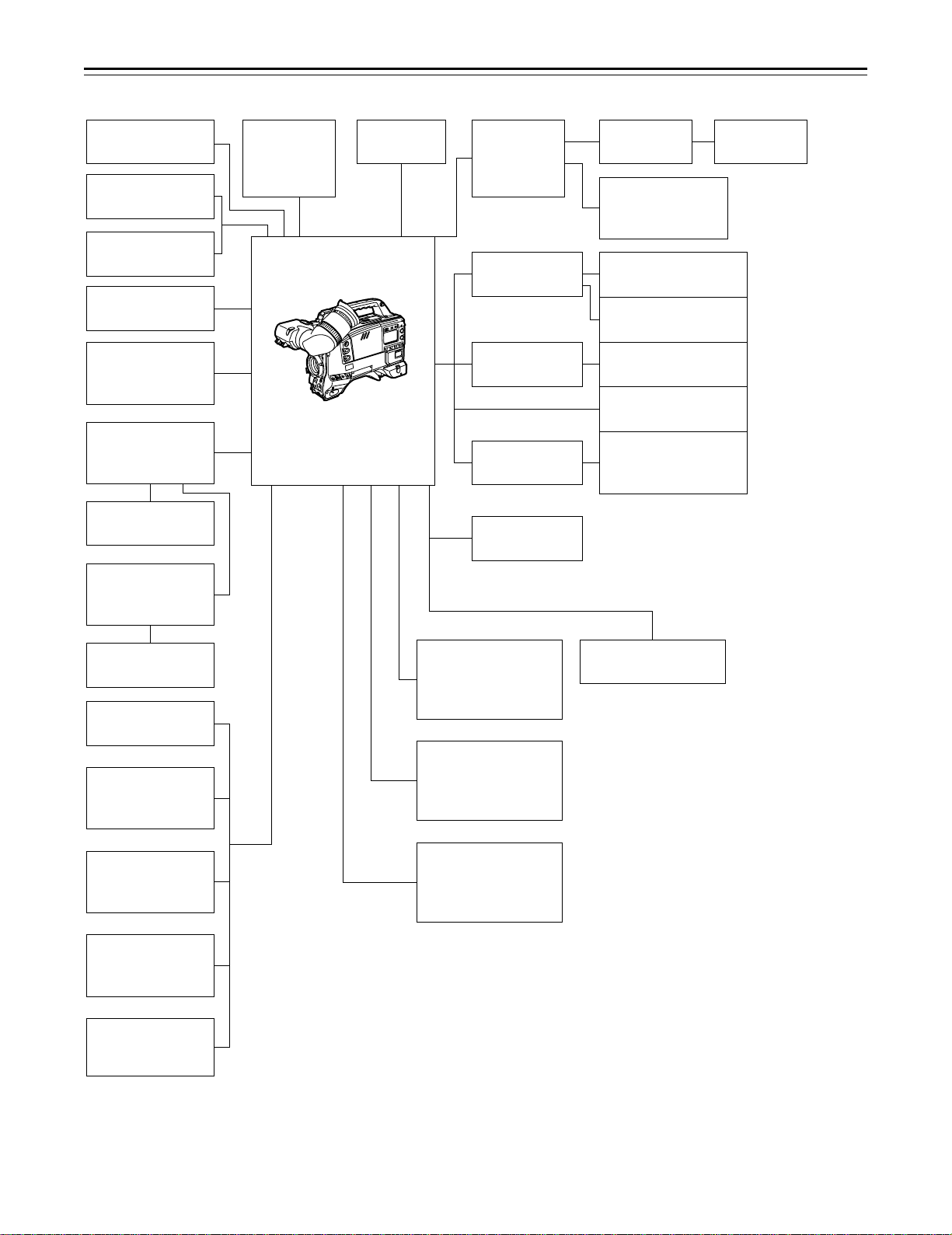
System Configuration
Microphone kit
AJ-MC700P
1.5½ viewfinder
AJ-VF10P/-VF15P
2.0½ viewfinder
AJ-VF20WP
Microphone holder
AJ-MH700P
Lens
(Bayonet type)
Fujinon/Canon
5w EVF mount
adaptor
AJ-QVF900
5w EVF AJ-VF53P
5w EVF mount
adaptor
AJ-YA711
Wireless
microphone
receiver
WX-RA700
Camera/VTR
AJ-SDC915
Shoulder
belt
26P/12P
output
adaptor
AJ-YA900P
Battery case
SHAN-B220
Battery case
AU-M402H
Battery case/
Battery holder
AC adaptor
AJ-B75
VTR cable VTR
Multi connector
cable
SHAN-C12TCA
Sony Battery NP-1
IDX Battery L-40
BP-90 type Battery
Anton Bauer Battery
Sony Battery
BP-90
BP-L60/BP-L90
5w EVF
WV-VF65B/C
Rain cover
SHAN-RC700
Soft carrying
case
AJ-SC900
Tripot mount
adaptor
SHAN-TM700
Extension control
unit
AJ-EC3
Carrying case
AJ-HT900
Cassette tape
ÁM size cassette tape
exclusively for
DVCPRO
Setup memory card
SHL-064HSRVS
Picture Link adaptor
board
AJ-YAP900
Cleaning tape
AJ-CL12MP
– 9 –
Page 10
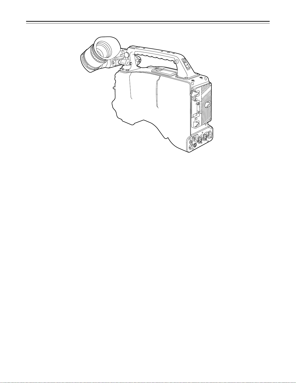
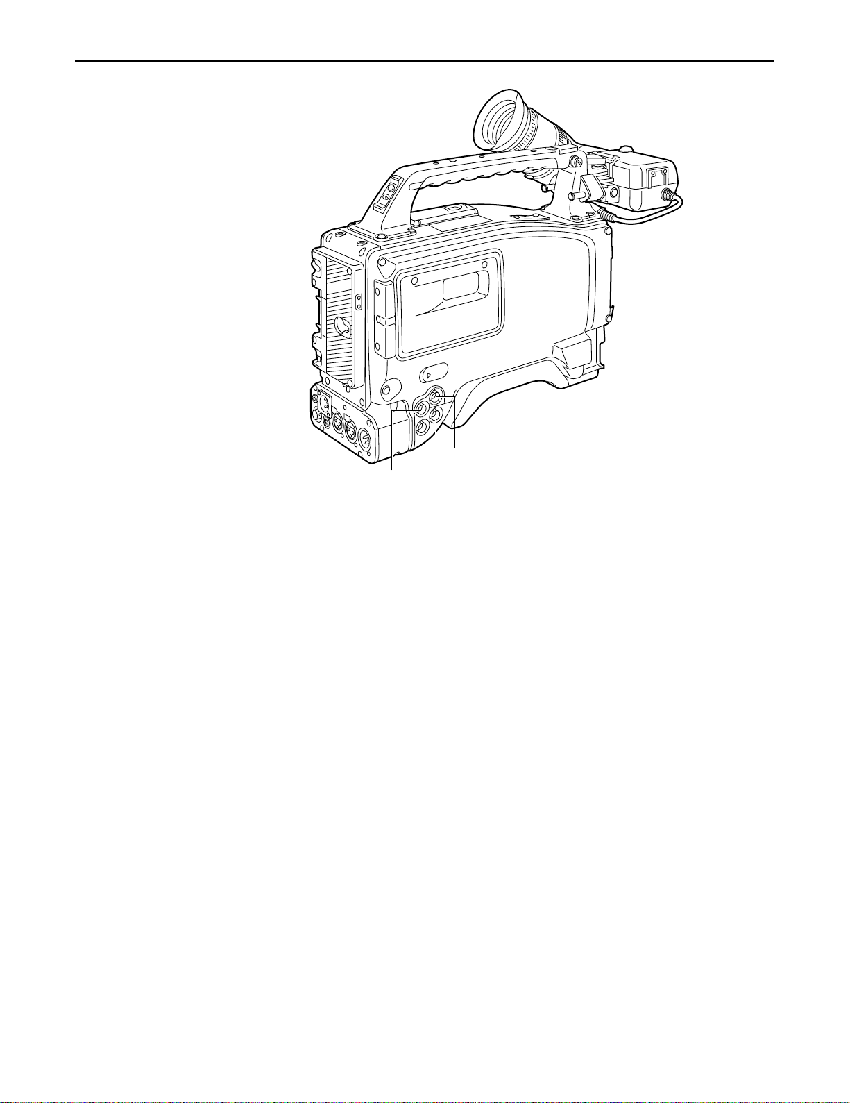
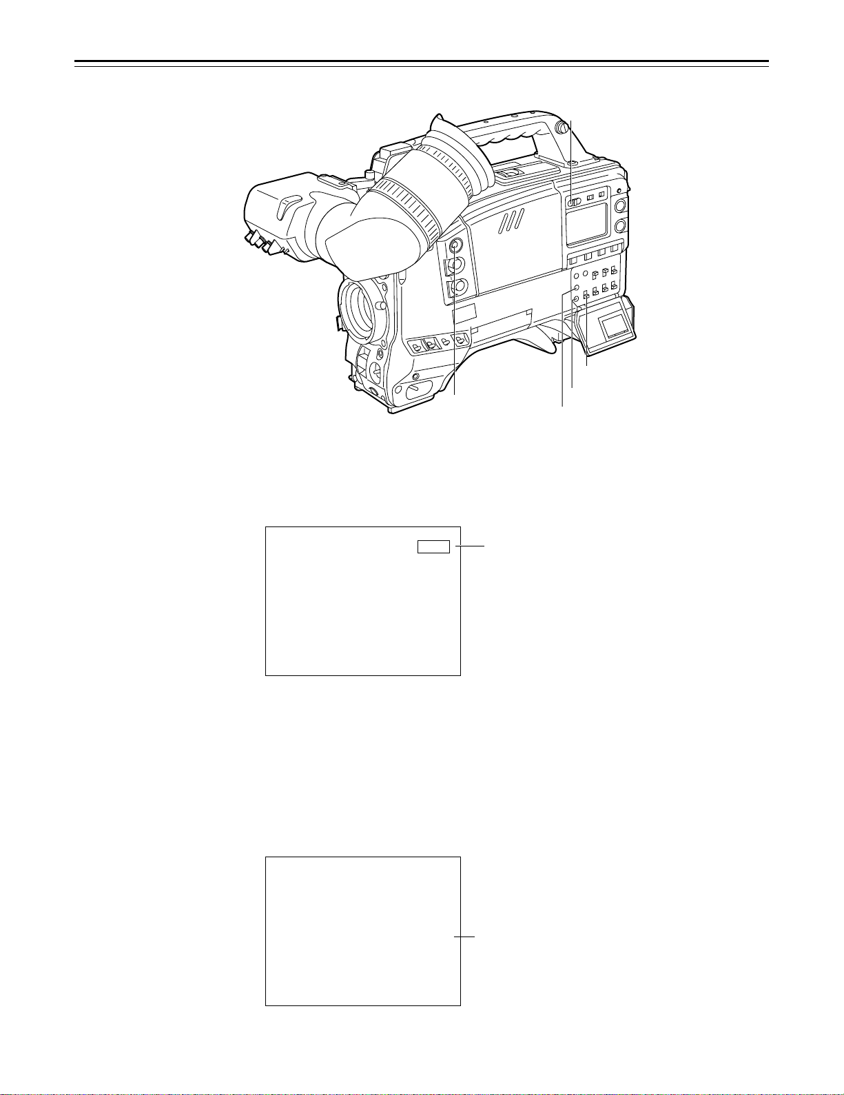
Controls and Their Functions
Power Supply Section
e Battery holder
The battery pack (option) made by Anton Bauer is mounted onto this holder.
f DC IN (external power input) connector (XLR, 4P)
The AJ-B75 AC adaptor (option) is plugged into this socket when the unit is to be operated by
AC power. An external battery is plugged in when an external battery is to be used to operate
the unit.
g BREAKER (circuit breaker) button
In order to protect the equipment, the circuit breaker is tripped and the power is automatically
turned off when an excessively high level of power flows inside. Upon completion of the internal
inspection and adjustments, push this button back in. The power will come back on provided
that there is no trouble inside the unit.
h POWER switch
ON: Set to this position to turn on the unit’s power.
OFF: Set to this position to turn off the unit’s power.
– 10 –
Page 11
Controls and Their Functions
5
6
5
7
9
8
n
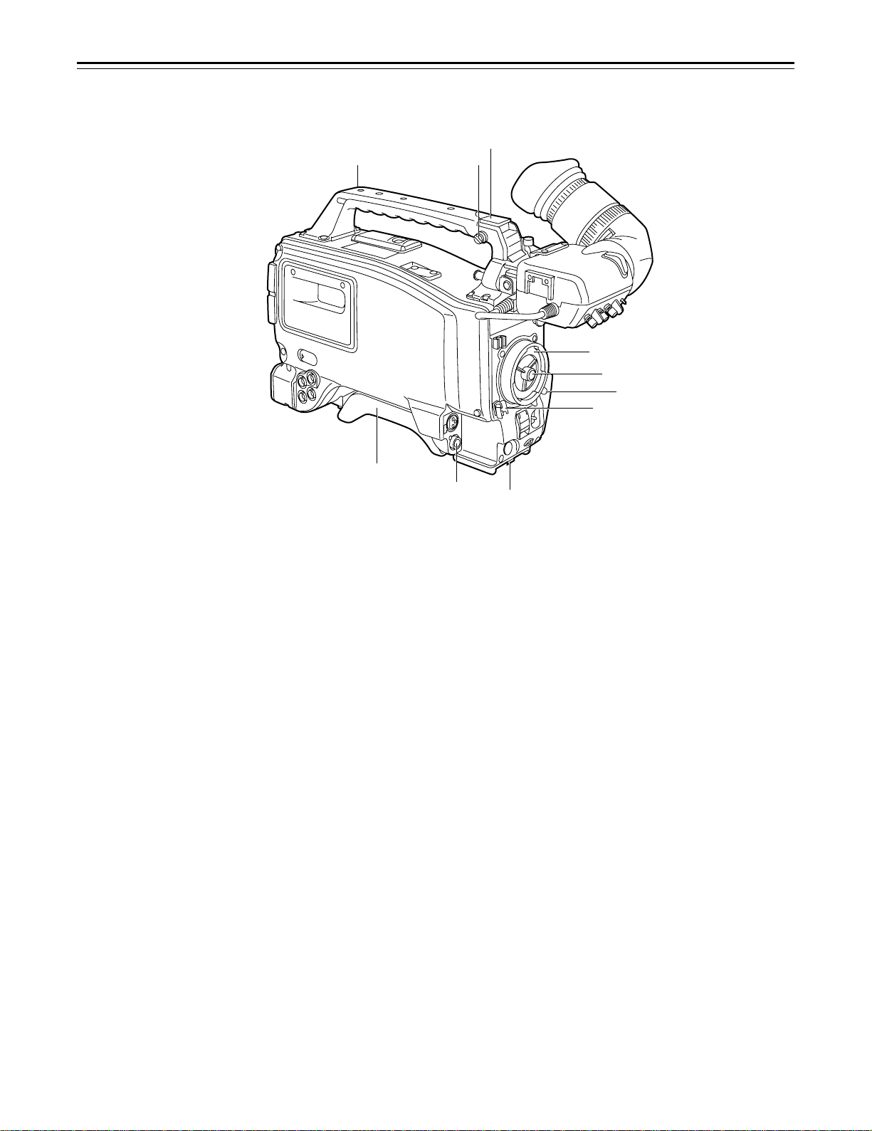
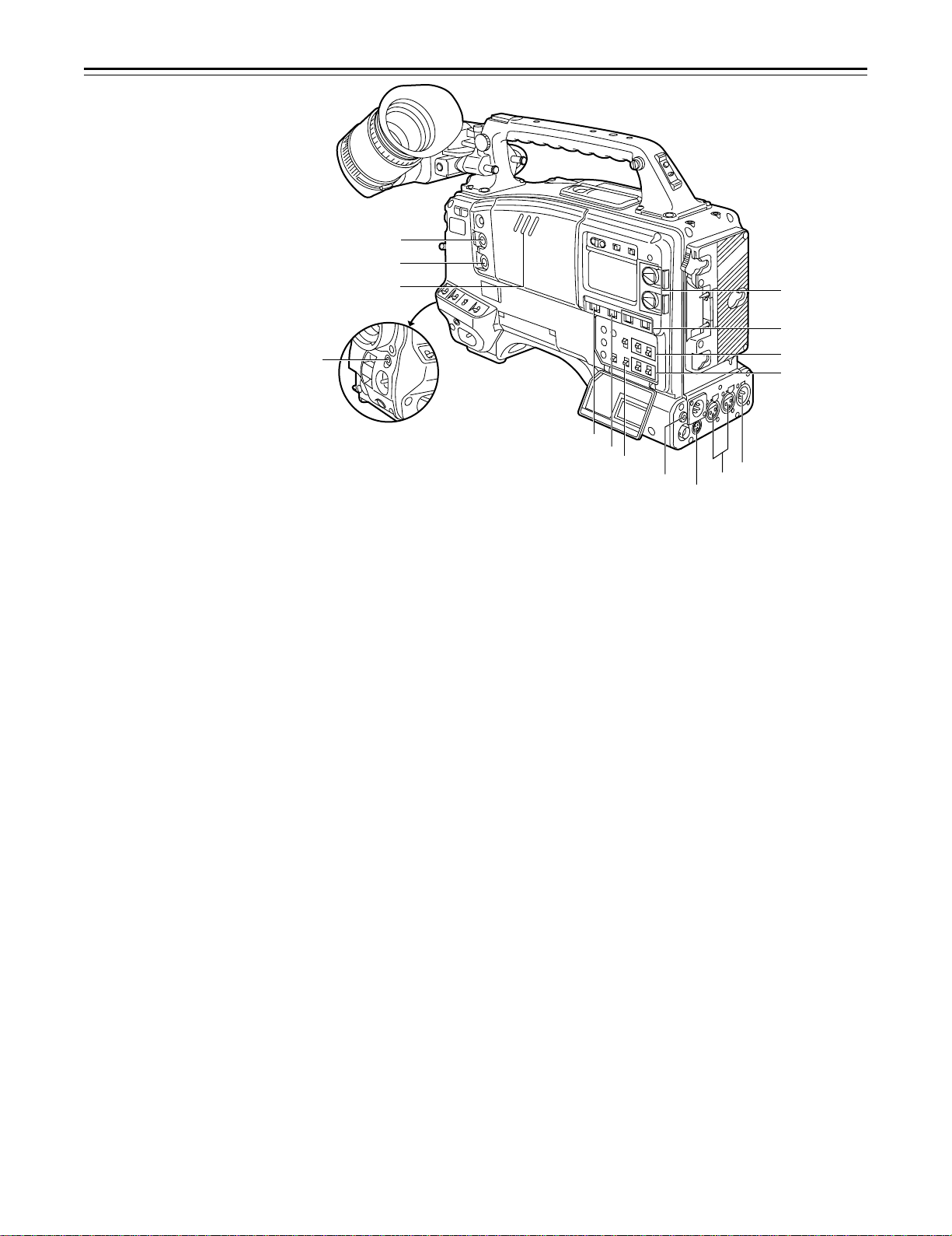
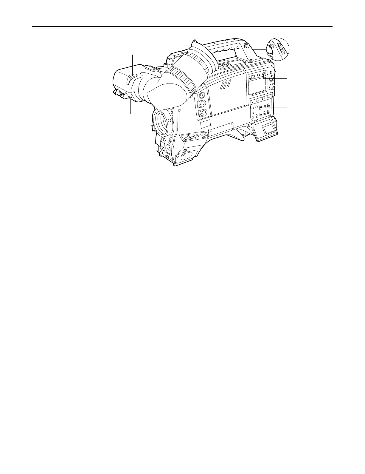
Accessory Mounting Section
i Hook for mounting shoulder belt
Attach the accessory shoulder belt to this hook.
j Light shoe
Mount the video light, etc. onto this shoe.
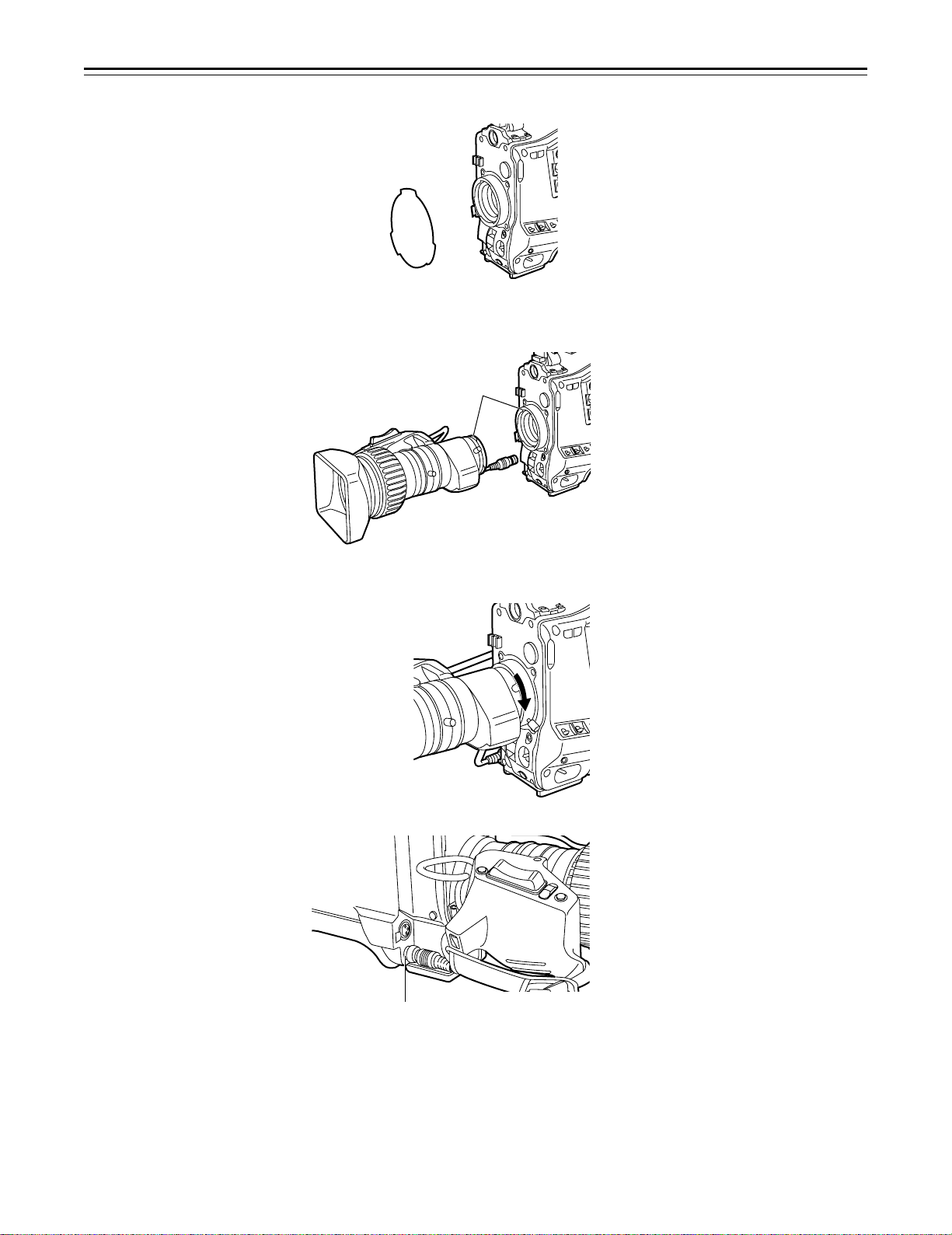
k Lens mount (bayonet type)
Mount the lens here.
l Lens clamping lever
Insert the lens into the lens mount k, and turn the lens mount ring using this lever to clamp the
lens.
m Lens mount cap
Press up the lens clamping lever l to remove this cap. Keep the cap in place if the lens is not
going to be mounted.
n Lens cable clamp
This is for clamping the lens cable.
o Tripod mount
When the unit is to be secured to a tripod, mount the tripod attachment (SHAN-TM700) which
is available as an optional accessory.
p LENS connector (12-pin)
Hook up the lens connecting cable to this connector. Consult with your dealer concerning the
lens which you are going to use.
q Shoulder pad
Adjust this pad to facilitate operation when carrying the unit on your shoulder. Its position can
be brought forward or backward and adjusted by loosening the two set screws.
q
p
o
– 11 –
Page 12
Controls and Their Functions
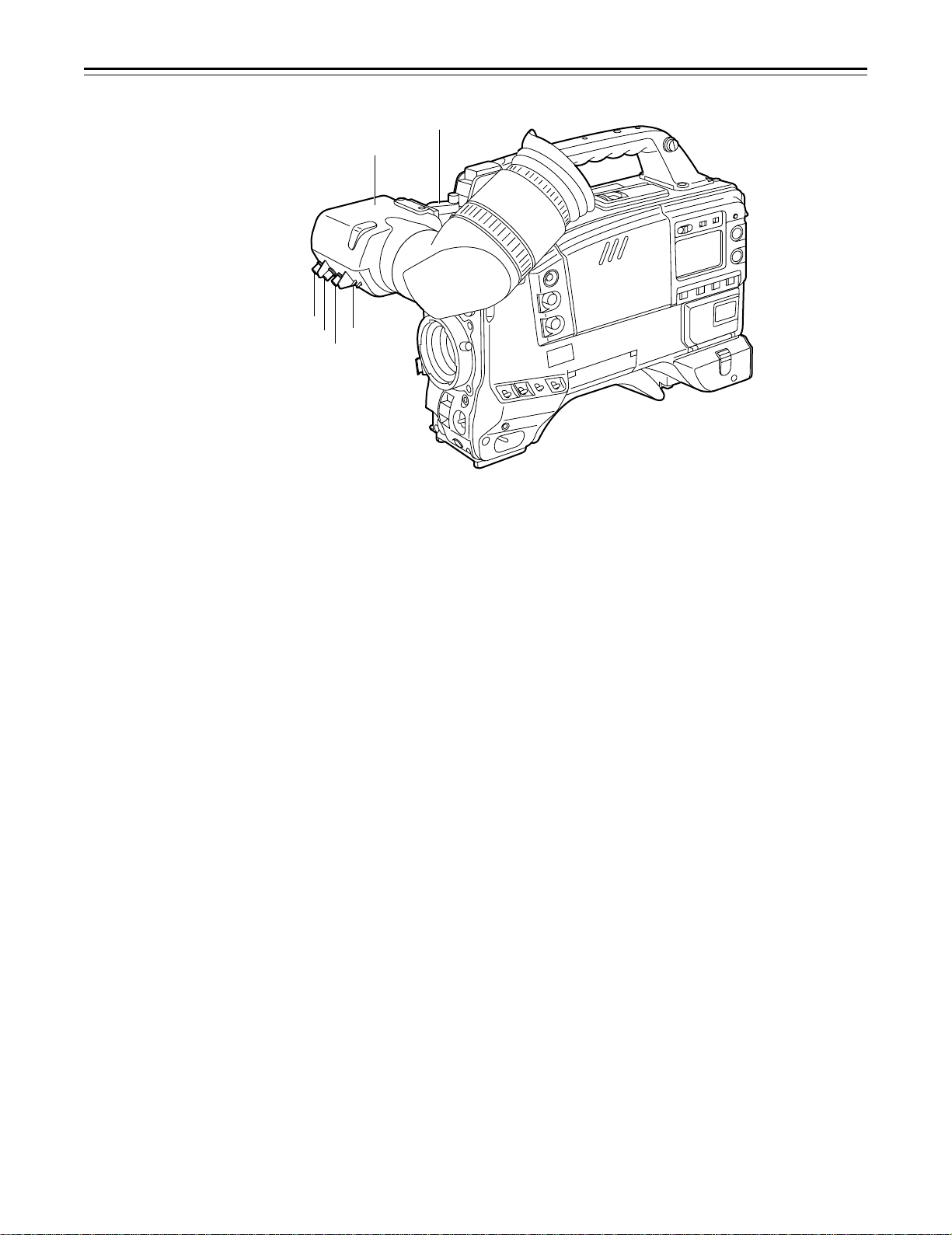
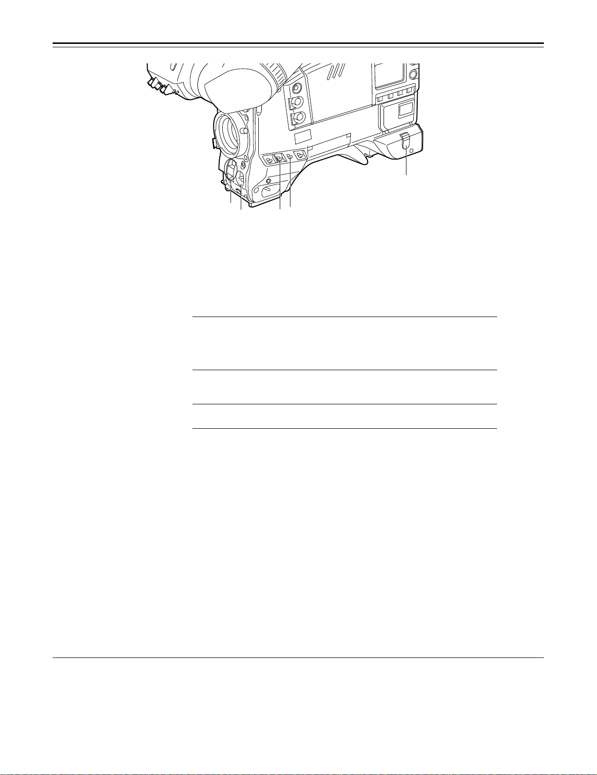
Audio Function Section (1)
r AUDIO LEVEL CH1 (audio channel 1 recording level) control
When the AUDIO SELECT CH1/CH2 switch u is set to MAN, the recording level of audio
channel 1 can be adjusted by this control in addition to the AUDIO LEVEL CH1 control t on
the side panel.
s MIC IN (microphone input) jack (XLR, 3-pin)
Connect an optional microphone to this jack. The power for the microphone is supplied from
this jack.
t AUDIO LEVEL CH1/CH2 (audio channel 1/2 recording level) controls
When the AUDIO SELECT CH1/CH2 switch u is set to MAN, the audio level of audio channels
1 and 2 can be adjusted using these controls.
However, the audio CH1 level can also be adjusted using the AUDIO LEVEL CH1 control r on
the front panel.
u AUDIO SELECT CH1/CH2 switch (audio channel 1/2 auto/manual level adjustment selec-
tor) switch
This selects the method used to adjust the audio levels of audio channels 1 and 2.
AUTO: For adjusting the levels automatically.
MAN: For adjusting the levels manually.
v AUDIO IN (audio input selector) switch
This selects the input signals to be recorded on audio channels 1 and 2.
FRONT [MIC]: The microphone input signals connected to the MIC IN jack s are recorded.
REAR [MIC]: The microphone input signals connected to the AUDIO IN CH1/CH2 connec-
tors y are recorded.
REAR [LINE]: The line input signals connected to the AUDIO IN CH1/CH2 connectors y
are recorded.
w REAR MIC POWER switch
ON: The phantom power is supplied to the rear microphone.
OFF: The phantom power is not supplied to the rear microphone.
x CUE switch
CH1: The audio CH1 signals are recorded on the cue track.
1/2: The signals of audio CH1 and CH2 are mixed together and recorded on the cue track.
CH2: The audio CH2 signals are recorded on the cue track.
y AUDIO IN CH1/CH2 (audio input channel 1/2) connectors (XLR, 3P)
An audio component or microphone is connected here.
z AUDIO OUT connector (XLR, 3P)
This is connected to an audio component. The audio channels are coupled to the MONITOR
SELECT switch and switched in tandem.
{ DC OUT (DC power output) connector
This is the DC 12 V output connector. A current of approximately 100 mA can be taken out.
– 12 –
Page 13
Controls and Their Functions
|
}
~
°
Audio Function Section (2)
| ALARM (warning tone volume) control
This adjusts the warning tone volume heard from the speaker ~ or the earphone connected to
the PHONES jack ¡. When it is set to the lowest position, the warning tone is not audible.
However, by making changes to the inside parts, the tone can be made audible even when the
control is at its lowest position.
} MONITOR (volume) control
This adjusts the volume of the sound other than the warning tone—the sound from the speaker
~ or earphone ¡. When it is set to the lowest position, no sound is heard.
†
x
°
{
y
t
u
v
w
z
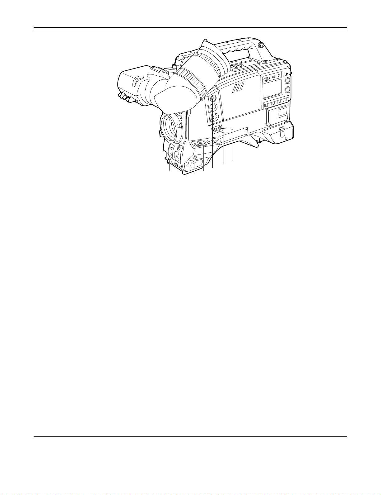
Audio Function Section (3)
~ Speaker
During recording, the EE sound can be monitored; during playback, the playback sound can be
monitored.
The warning tone is heard through the speaker in synchronization with the flashing or lighting
of the warning lamp and warning display.
The speaker sound is automatically muted when an earphone is connected to the PHONES
jack ¡.
MONITOR SELECT (audio channel selector) switch
This selects the audio channel whose sound is to be heard through the speaker ~ AUDIO
OUT connector z, or earphone.
CH1: The audio channel 1 sound is output.
1/2: The sound produced by mixing the audio channel 1 and 2 sound or the stereo sound is
output. However, only the mixed sound is output from the speaker ~ and AUDIO OUT
connector z.
CH2: The audio channel 2 sound is output.
MONITOR (sound selector) switch
This selects the sound of the earphone when 1/2 is selected with the MONITOR SELECT
switch .
ST: The stereo sound of audio channels 1 and 2 is output.
MIX: The mixed sound of audio channels 1 and 2 is output.
¡ PHONES (earphone) jack (mini-jack)
When an earphone (option) is connected to this jack, the sound selected by the MONITOR
switch can be heard. The warning tones relating to the unit’s operation or status can also be
heard. An earphone enabling a sufficiently high volume of sound to be heard is recommended.
When the earphone is connected, speaker ~ sound is automatically muted.
– 13 –
Page 14
Controls and Their Functions
¢
£
¶
§
•
©
(The viewfinder shown in the illustration is the AJ-VF10P.)
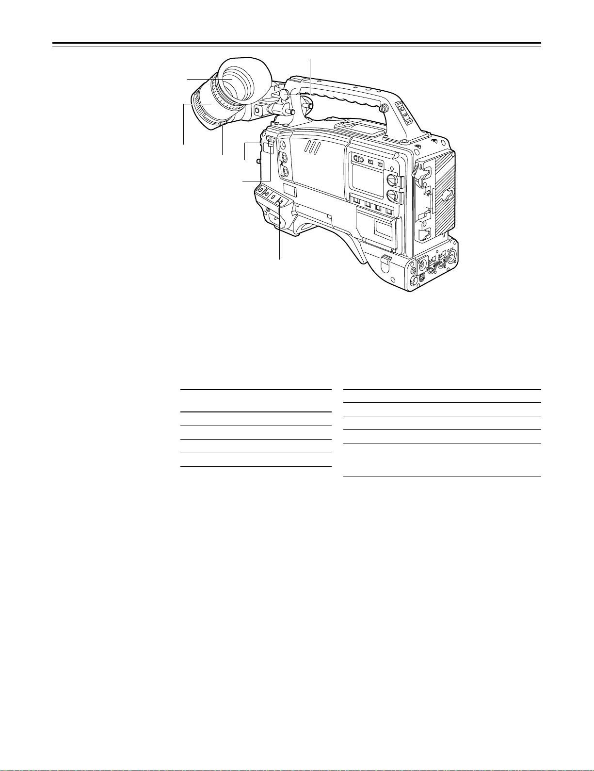
Shooting (Recording)/Playback Function Section (1)
¢ Viewfinder (optional accessory)
Black-and-white images can be seen in the viewfinder during recording and playback. Warnings and messages relating to the unit’s operating status and settings, zebra pattern, markers
(safety zone marker, center marker), etc. can also be seen.
£ PEAKING control
This is used to adjust the contours of the images inside the viewfinder to facilitate focusing. It
does not affect the camera’s output signals.
¤ CONTRAST control
This is used to adjust the contrast of the screen inside the viewfinder. It does not affect the
camera’s output signals.
¥ BRIGHT control
This is used to adjust the brightness of the screen inside the viewfinder. It does not affect the
camera’s output signals.
¦ ZEBRA (zebra pattern) switch
This displays the zebra pattern inside the viewfinder.
ON: The zebra pattern is displayed.
OFF: The zebra pattern is not displayed.
When the unit is shipped from the factory, the zebra pattern is set in such a way that those
parts with an IRE video level from approx. 70% to 85% are displayed. The displaying of parts
with a level ranging from 50% to 110% or more or with a certain level can also be set on the
setting menu.
§ Diopter control knob
This is adjusted in such a way that the images on the viewfinder screen are seen most clearly
in accordance with the dioptric power of the camera’s operator.
¨ Eyepiece
© Viewfinder forward-backward/left-right position clamp lever
Loosen this lever to adjust the position of the viewfinder ¢ in the forward-backward or left-right
direction.
ª Eyepiece forward-backward movement ring
Turn this ring to adjust the position of the eyepiece ¨ in the forward-backward direction.
« Viewfinder stopper screw
To detach the viewfinder ¢ from the camera, loosen this screw and then detach the viewfinder.
– 14 –
Page 15
Controls and Their Functions
®
™
ß
¨
≠
´
(The viewfinder shown in the
illustration is the AJ-VF10P.)
Æ
Shooting (Recording)/Playback Function Section (2)
¬ CC/ND FILTER (filter selector) knob
This selects the filter to match the light source which is illuminating the subject.
If the setting of this knob is changed when the menu display mode has been set to “3” (default
setting), the new setting will appear on the setting change message display area of the viewfinder screen.
È The knob and filter settings are
listed below.
FILTER
knob setting
1 3200 K
2 5600 Ko1/8ND
3 5600 K
4 5600 Ko1/64ND
Synchro scan adjustment switches
These switches are used to adjust the synchro scan speed. Pressing the “p” switch reduces
the shutter speed; pressing the “o” switch increases the shutter speed. Set these switches to a
position where the side bar noise in the viewfinder is eliminated during personal computer
monitor shooting, etc.
|Note{
When these switches are used for UB/TC/CTL settings while the SET position has been selected as the TCG switch position, they will not serve their function as synchro scan adjustment
switches. The TCG switch must be set to F-RUN or R-RUN for these switches to serve their
function.
® WHITE BAL (white balance memory selector) switch
PRST: Set to this position when there is no time to adjust the white balance. The white bal-
A or B: When the AUTO W/B BAL switch ± is pressed to the AWB side, the white balance
When the FILTER knob and the WHITE BAL switch are set to the same positions as the ones
set when the adjustment was made, the adjustment value stored in the memory is called, and
the unit is automatically adjusted to the white balance which corresponds to this value.
If the setting of this switch is changed when the menu display mode has been set to “3” (default
setting), the new setting will appear at the WHITE BAL switch display position on the viewfinder
screen. (Example: “A”)
Description
ance value for 3200K is stored in the memory.
is automatically adjusted in accordance with the setting position of the filter knob ¬,
and the adjustment value is stored in memory A or memory B.
È Examples of filter settings to match
shooting conditions
Filter Shooting condition
1 Sunrise, sunset, inside a studio
2 Outdoors under a clear sky
3 Outdoors under a cloudy or rainy sky
4 Snow scenes, high mountains,
coastlines and other extremely clear
and bright scenes
– 15 –
Page 16
Controls and Their Functions
≥
≤
±
∞
Ø
Shooting (Recording)/Playback Function Section (3)
¯ OUTPUT (output signal selector)/AUTO KNEE switch
This switch selects the video signals which are to be output from the camera unit to the VTR
unit, viewfinder and video monitor. The AUTO KNEE function can be used when the images
shot by the camera have been selected.
È OUTPUT/AUTO KNEE switch setting positions
BARS Color bar signals are output. The AUTO KNEE circuit
is not activated. Set the switch to this position in the
following cases:
ÁWhen adjusting the video monitor
ÁWhen recording color bar signals
CAM, AUTO KNEE OFF The images shot by the camera are output.
CAM, AUTO KNEE ON The images shot by the camera are output.
° GAIN (gain selector) switch
This is used to change the video amplifier’s gain in accordance with the lighting conditions
during shooting. The gain values corresponding to the L, M and H settings are assigned beforehand on the setting menu. When the unit is shipped from the factory, these settings are:
Lr0 dB, Mr9 dB and Hr18 dB.
If the setting of this switch is changed when the display mode has been set to “3”, the new
setting will appear at the gain display position on the viewfinder screen. (Example: “12 dB”)
± AUTO W/B BAL (white balance/black balance automatic adjustment) switch
AWB: Set to this position for automatically adjusting the white balance. When the WHITE BAL
switch ® is now set to “A or B”, the adjusted value will be stored in memory A or
memory B.
ABB: Set to this position for automatically adjusting the black balance. When this switch is
held down for at least 10 seconds at the ABB position, the auto black shading will be
compensated automatically.
² SHUTTER switch
Set this to ON when using the electronic shutter. When it is pressed to the SEL side, the shutter
speed and mode displays change in the ranges preset on the setting menu. If the setting of this
switch is changed when the display mode has been set to “2” or “3”, the new setting will appear
at the shutter display position on the viewfinder screen. (Example: “:1/250”, “:1/60.8”)
The AUTO KNEE circuit is not activated. The default
setting is “MANUAL KNEE”.
The AUTO KNEE circuit is activated.
1) AUTO KNEE function
When the level is adjusted to people, scenes, etc. for shooting against a very bright background, the background will be whited out and the
buildings or scenes in the background will become blurred. If the AUTO KNEE function is activated in cases like these, the background can be
reproduced in clear detail. This function is especially effective for shooting in the following conditions:
ÁWhen shooting people in shade under a clear sky
ÁWhen simultaneously shooting people in vehicles or indoor and the outdoor scenery seen through the windows
ÁWhen shooting scenes with a high contrast
– 16 –
Page 17
Controls and Their Functions
µ
∂
¥
³ ECU REMOTE (remote control) connector (6-pin)
Connect the AJ-EC3 extension control unit (option) here.
|Note{
The POWER switches on unit and extension control unit must be set to OFF before the remote
control cable is connected or disconnected.
´ 26-pin/12-pin output adaptor (See page 104 for mounting method.)
The 26-pin/12-pin output adaptor AJ-YA900P (option) is mounted on this section. When the
portable VTR is connected as the external VTR, recording can be performed simultaneously
with the unit’s built-in VTR.
Furthermore, by connecting the SHAN-C12TCA multi-connector cable (optional accessory) to
the 12-pin connector, it is possible to output the sound of audio channels 1 and 2 separately.
µ VIDEO OUT connector (BNC)
This outputs the video signals (75° termination, rated level) to be monitored. During recording,
EE images can be monitored; during playback, playback images can be monitored.
While performing settings on the menu, the setting menu can be superimposed onto the shot
images appearing on the monitor screen so that the settings can also be checked.
¶ CAM OUT (camera output) connector (BNC)
This outputs the composite video signals (75° termination, rated level). When a video monitor
is connected, the images shot by the camera can be monitored. Even while the VTR is playing
back, the camera’s images are output at all times.
– 17 –
Page 18
Controls and Their Functions
ª
∫
∑
Shooting (Recording)/Playback Function Section (4)
· VTR START button
When this pressed, recording commences; when it is pressed again, recording stops. This
button has the same function as the VTR button on the lens side.
¸ VTR SAVE/STBY (tape protection) switch
This selects the power supply status while the VTR recording is temporarily stopped (REC
PAUSE).
SAVE: This is the tape protection mode. The cylinder is stopped in the half-loading status.
Compared with the STBY position, less power is consumed and the unit can be
operated longer using the battery. It takes longer for recording to commence after
the VTR START button · is pressed in the SAVE position than in the STBY position.
When the switch is set to this position, the VTR SAVE lamp inside the viewfinder
lights.
STBY: Recording commences immediately when the VTR START button is pressed.
|Note{
This unit will automatically go into SAVE mode when the designated time for standby (STBY)
condition is exceeded. To return to standby mode, press the VTR SAVE/STBY switch once to
select SAVE mode, then once again to return to STBY mode.
¹ MODE CHECK button
While this button is kept depressed, the camera’s setting status is displayed in the viewfinder. It
does not affect the camera’s output signals.
º SUPER GAIN button (inside sliding cover)
The super gain mode is forcibly established when this button is pressed, and each time the
button is pressed when all the super gain values have been set using “SUPER GAIN” on the
MAIN menu 2 of 4 screen, the gain is switched by one level in the following sequence: 30 dB>
36 dB>OFF>30 dB, etc. However, the DTL and other menu settings cannot be performed.
» SUPER IRIS button (inside sliding cover)
This is used when backlight compensation (or the super black functionF
When it is pressed, the switch settings are displayed inside the viewfinder for 3 seconds. When
it is pressed again, backlight compensation (or the super black functionF
1
F
See Main Menu Screen 2 of 4 on page 126 for details on the super black function.
º
∏
π
1
) is to be provided.
1
) is released.
Super gain: When 30 dB is allotted to the SUPER IRIS button, DTL and other menu settings cannot be performed for this
30 dB.
– 18 –
Page 19
Controls and Their Functions
ø
æ
Ω¿¡
¬
¼ MARK button
This is used when the Picture Link (Pix Link)F
(MARK1), M2 (MARK2) or no display appears in the viewfinder.
1
F
Picture Link adaptor board (AJ-YAP900) is sold as an option.
½ EJECT (cassette eject) button
Press this to insert or eject the cassette.
¾ REW (rewind) button
Press this to rewind the tape. Its lamp lights during rewinding.
If this button is pressed during playback, the playback images are rewound at approximately
quadruple speed while the button is held down.
¿ FF (fast forward) button
Press this to fast forward the tape. Its lamp lights during fast forwarding.
If this button is pressed during playback, the playback images are fast forwarded at approximately quadruple speed while the button is held down.
À PLAY/PAUSE button
Press this to view the playback images on the viewfinder screen or color video monitor. Its
lamp lights during playback.
If this button is pressed again during playback, playback is paused and the lamp goes off. After
playback has been paused for 2 minutes, the unit automatically switches to stop status
(STOP).
Á STOP button
Press this to stop the tape travel.
 EMERGENCY screw (inside the rubber cap)
For details, refer to the “emergency eject” function (on page 151).
1
function is to be used. Each time it is pressed M1
– 19 –
Page 20

Controls and Their Functions
Menu Operation Section
à Setup card insertion slot
The optional setup cards are inserted into this slot.
Ä MENU SET/OFF switch
This displays the setting menu on the viewfinder screen through VIDEO OUT connector.
SET: The page on which the previous setting menu operations were completed appears on
OFF: The setting menu is not displayed on the viewfinder screen through VIDEO OUT con-
Å SHIFT/ITEM button
Each time this button is pressed, the cursor moves on the setting menu page now displayed.
Use it when selecting items.
|Note{
This switch functions differently depending on the operation item. Check the function by operating the menu item by item.
Æ UP button
This is used to increment the setting of the item selected on the setting menu by 1 level each
time it is pressed or to switch the setting between ON and OFF.
Ç DOWN button
This is used to decrement the setting of the item selected on the setting menu by 1 level each
time it is pressed or to switch the setting between ON and OFF.
È PAGE button
This is used to select the setting menu page.
the viewfinder screen. (When the menu is used for the first time, the first of the pages
which can be displayed appears.)
nector.
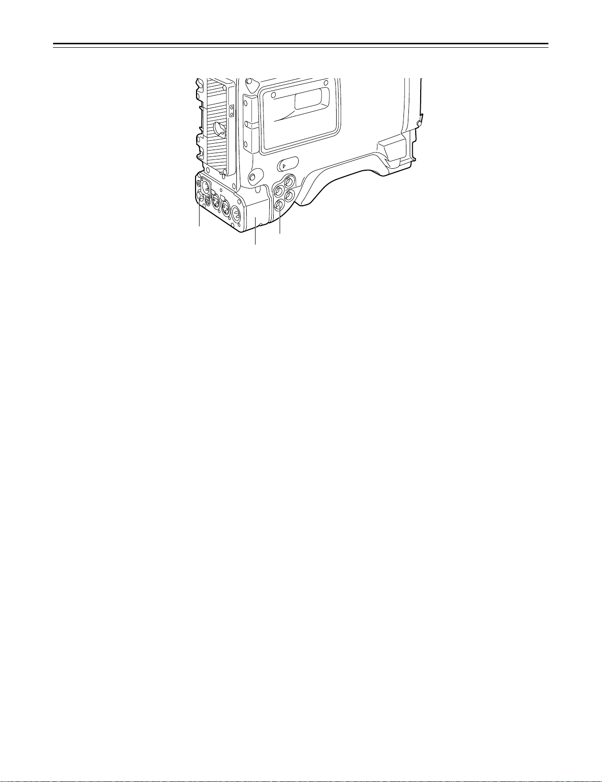
Time Code-Related Section (1)
É GENLOCK IN/(VIDEO IN) connector (BNC)
The reference signal is supplied to this connector when the camera section is to be subject to
genlock operation or when the time code is to be locked externally. This connector serves as
an external video input connector when REC SIGNAL: VIDEO has been selected on the setting
menu.
– 20 –
Page 21
Controls and Their Functions
Ê TC IN connector (BNC):
The time code serving as the reference is input when the time code is locked to an external
source.
Ë TC OUT connector (BNC):
Connect this to the time code TC IN connector on the external VTR when locking the external
VTR’s time code to this unit’s time code.
Time Code-Related Section (2)
Ì HOLD button
The time data appearing on the counter display at the instant when this button is pressed is
held. (The time code generator will still continue to run.) When the button is pressed again, the
hold status is released. Use the button to ascertain the time at which a particular scene was
shot, for example.
Í RESET button
This resets the time data on the counter display to “00:00:00:00”. When the TCG switch Ñ is
set to SET and this button is pressed, the time code or user’s bit can be reset to “00:00:00:00”
or “00 00 00 00”.
Î DISPLAY switch
The time code, CTL or user’s bit is made to appear on the counter display depending on the
setting positions of this switch and the TCG switch Ñ.
UB: The user’s bit is displayed.
TC: The time code is displayed.
CTL: CTL is displayed.
Ï UP button, DOWN button
When setting the time code or user’s bit, these buttons increment or decrement by 1 the figure
of the digit made to flash by the SHIFT/ITEM button Ð.
Ð SHIFT/ITEM (digit advance) button
When setting the time code or user’s bit, this button is used to cause the digit which is to be set
to flash.
…
À
– 21 –
Page 22
Controls and Their Functions
“
’
÷
◊
ÿ
—
”
(The viewfinder shown in the illustration is the AJ-VF10P.)
Ñ TCG (time code selector) switch
This is used to set the running mode of the internal time code generator.
F-RUN: This position is used when the time code is to be advanced continuously regardless of
the VTR’s operation.
Set to this position when aligning the time code with the actual time or locking the time
code to an external source.
SET: This position is used for setting the time code or user’s bit.
R-RUN: This position is used when the time code is to be advanced only while recording is in
progress. The time code will be recorded continuously on a tape with a succession of
unedited shots.
‘
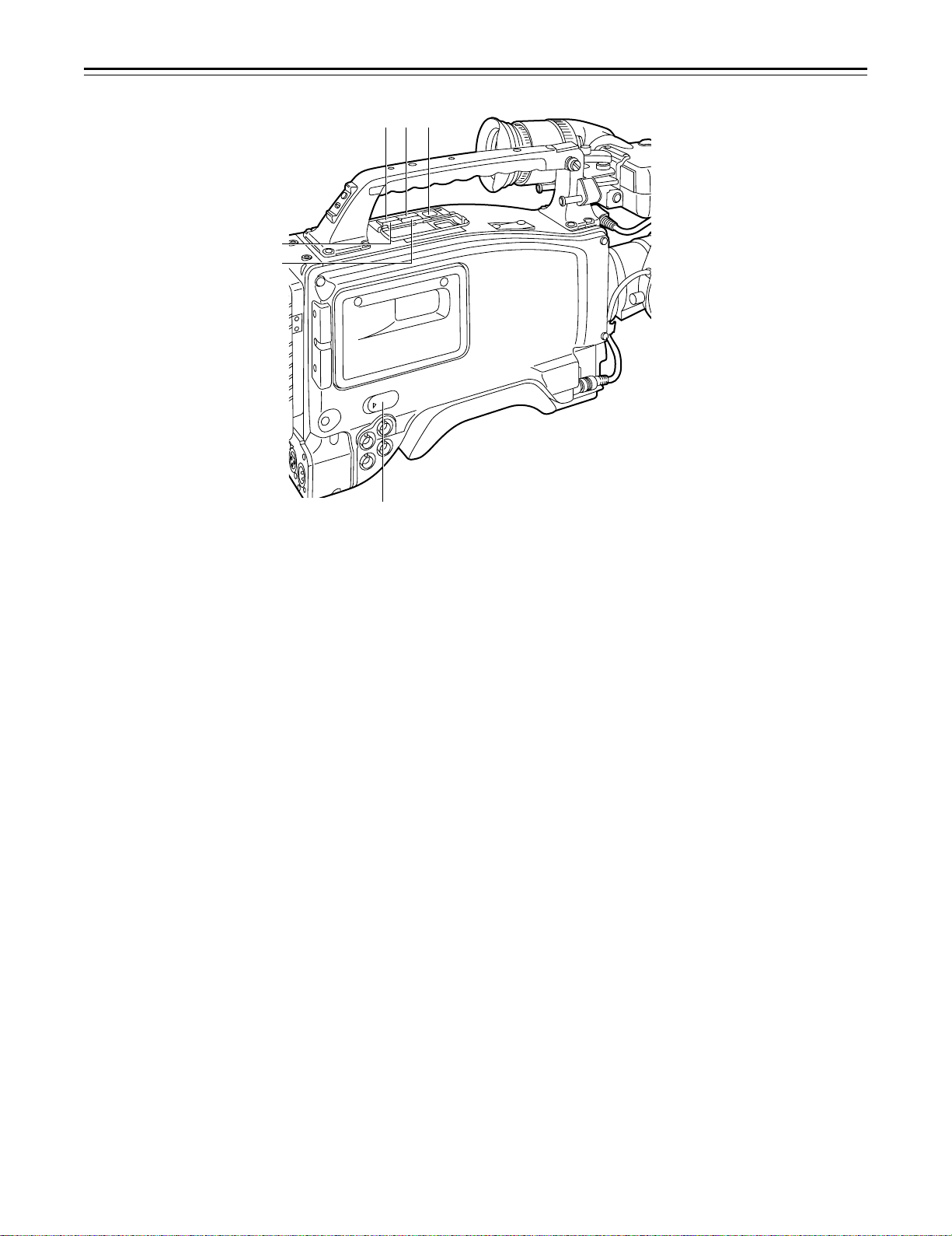
Warning/Status Display Section
Ò Tally lamp
This is activated when the TALLY switch Ó is at HIGH or LOW, and it lights during recording by
the VTR section. It flashes in the same way as the REC lamp inside the viewfinder to warn the
operator. The brightness when lighted can be selected using the TALLY switch (HIGH or
LOW).
Ó TALLY switch
This controls the tally lamp Ò.
HIGH: The tally lamp is made brighter.
OFF: The tally lamp is extinguished.
LOW: The tally lamp is made darker.
Ô Back tally lamp
This functions in the same way as the tally lamp Ò when the back tally switch Õ is set to ON.
Õ Back tally switch
This controls the back tally lamp Ô.
ON: The back tally lamp operates.
OFF: The back tally lamp does not operate.
Ö WARNING lamp
This flashes or lights when trouble occurs in the VTR section.
× LIGHT switch
ON: This illuminates the display window Ø.
OFF: This extinguishes the display window illumination.
Ø Display window
The warnings related to the VTR section, remaining battery level, sound level, time data, etc.
are displayed in this window.
–22–
Page 23
– 23 –
Page 24
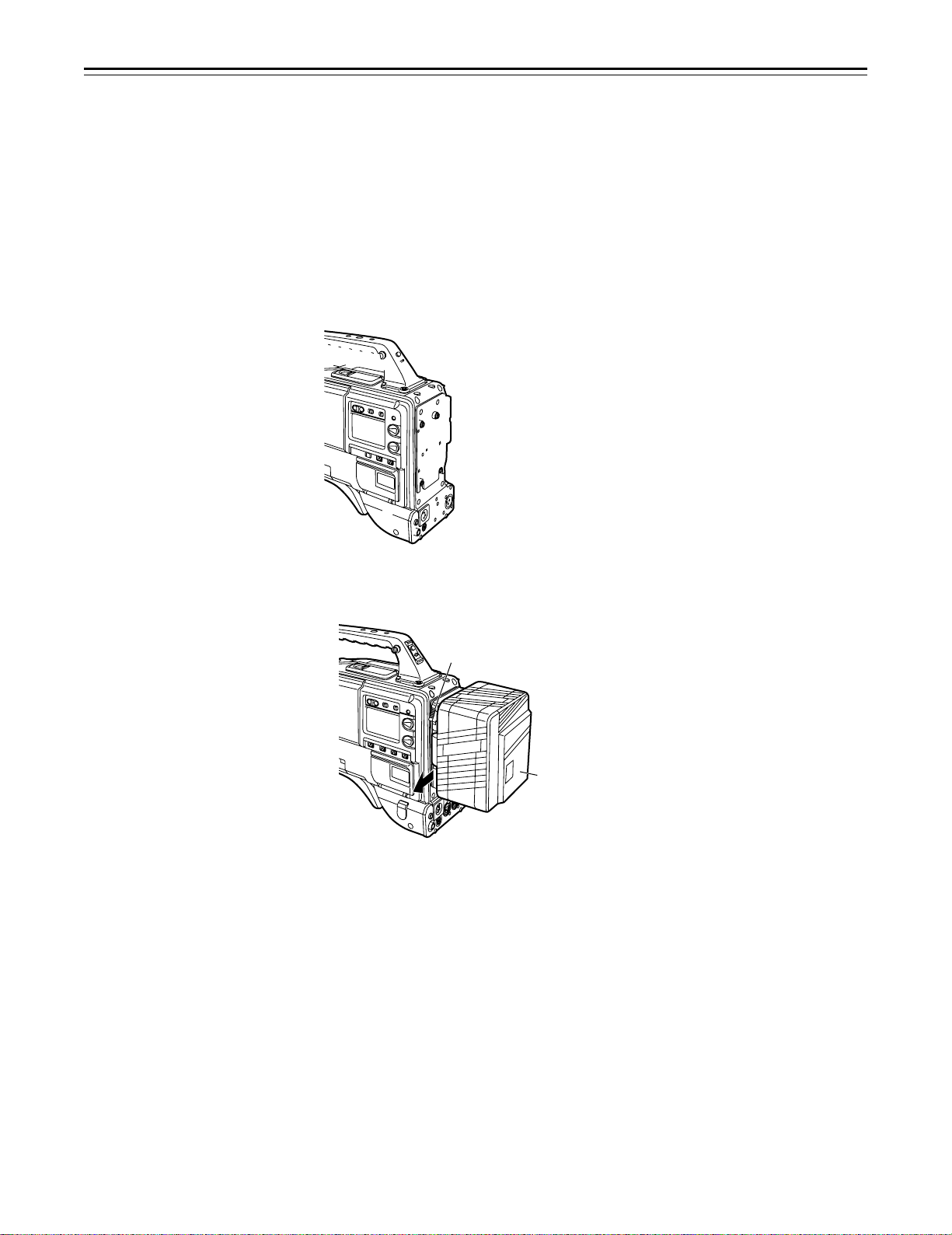
Power Supply
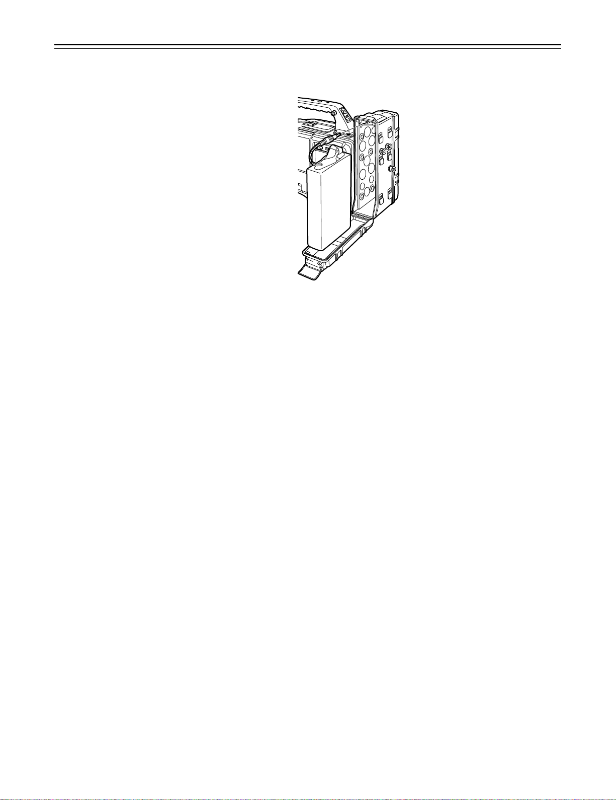
Using the BP-90 type Battery Pack
1 Detach the battery mounts.
2 Connect the unit’s connectors with the connectors of the AU-M402H battery case.
3 Mount the AU-M402H battery case.
Open the battery case cover and lift up the rubber cap to expose the screw holes. Tighten the
screws with a screwdriver and mount the case to the unit. Be sure to tighten the screws
completely.
|Notes{
ÁDo not pull strongly on the rubber cap.
ÁTake care not to catch the connection cord between the battery case and the main unit.
– 24 –
Page 25
Power Supply
4 Connect the battery pack plug to the connector inside the case and insert the battery pack.
|Note{
The unit’s power must be set to OFF before the plug is inserted or removed.
– 25 –
Page 26
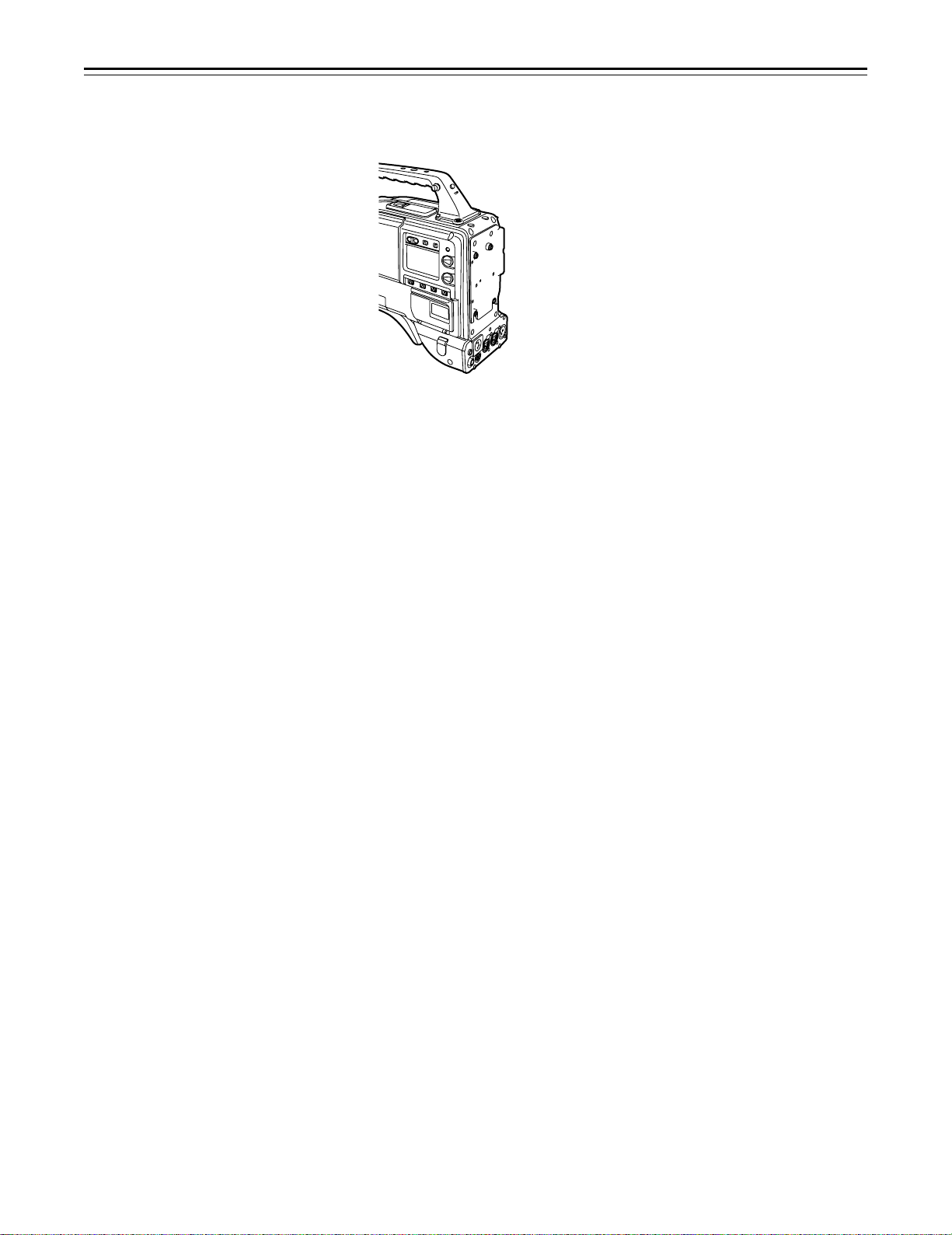
Power Supply
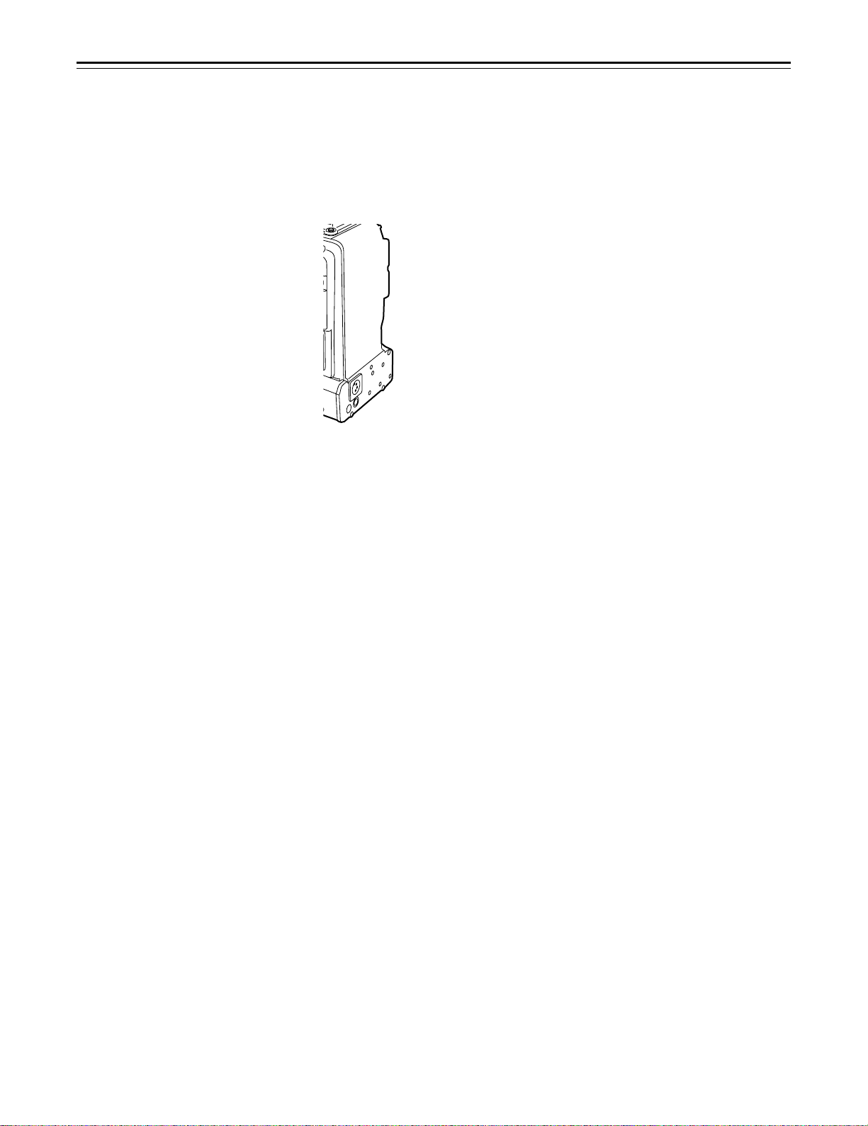
Using a Sony Battery Pack
1 Remove the battery mounts.
See page 24.
2 Mount the accessory battery mounting connector.
3 Mount the Sony battery holder.
Mount the battery case with the cover detached first, and then mount the detached cover as
shown in the figure.
A Tighten the mounting screws.
B Tighten the power supply contact screws.
C Insert the top of the detached cover in the direction of the arrow.
D Align the hole at the bottom (metal part) of the cover with the hole at the bottom of the case
and mount the cover to the battery mounting connector with the screw of the battery
holder.
|Note{
Take care when attaching the battery holder that the wires are not pinched.
– 26 –
Page 27
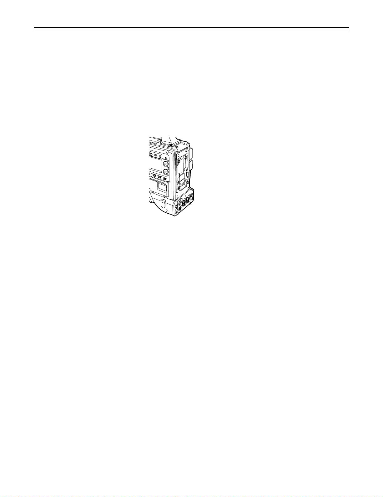
Using the Sony BP-90 Battery Pack
1 Mount the accessory battery mounting connector.
(See the preceding page.)
2 Mount the BP-90 battery case.
A Tighten the mounting screws.
B Tichten the power supply contact screws.
C Insert the top of the detached cover in the direction of the arrow.
D Align the hole at the bottom (metal part) of the cover with the bottom of the case and mount
the cover to the battery mounting connector with the screw.
Using the Sony BP-L60/BP-L90 lithium-ion Battery Pack
1 Attach the supplied battery mounting terminals.
2 Attach the lithium-ion battery holder.
A As shown in the figure, remove the battery clamp, and attach the holder using the mount-
ing screws.
B Tighten the power supply contact screws.
C Put the battery clamp back into place.
|Notes{
ÁThe unit’s power must be set to OFF before the plug is inserted or removed.
ÁTake care when attaching the battery case/battery holder that the wires are not pinched.
– 27 –
Page 28
Power Supply
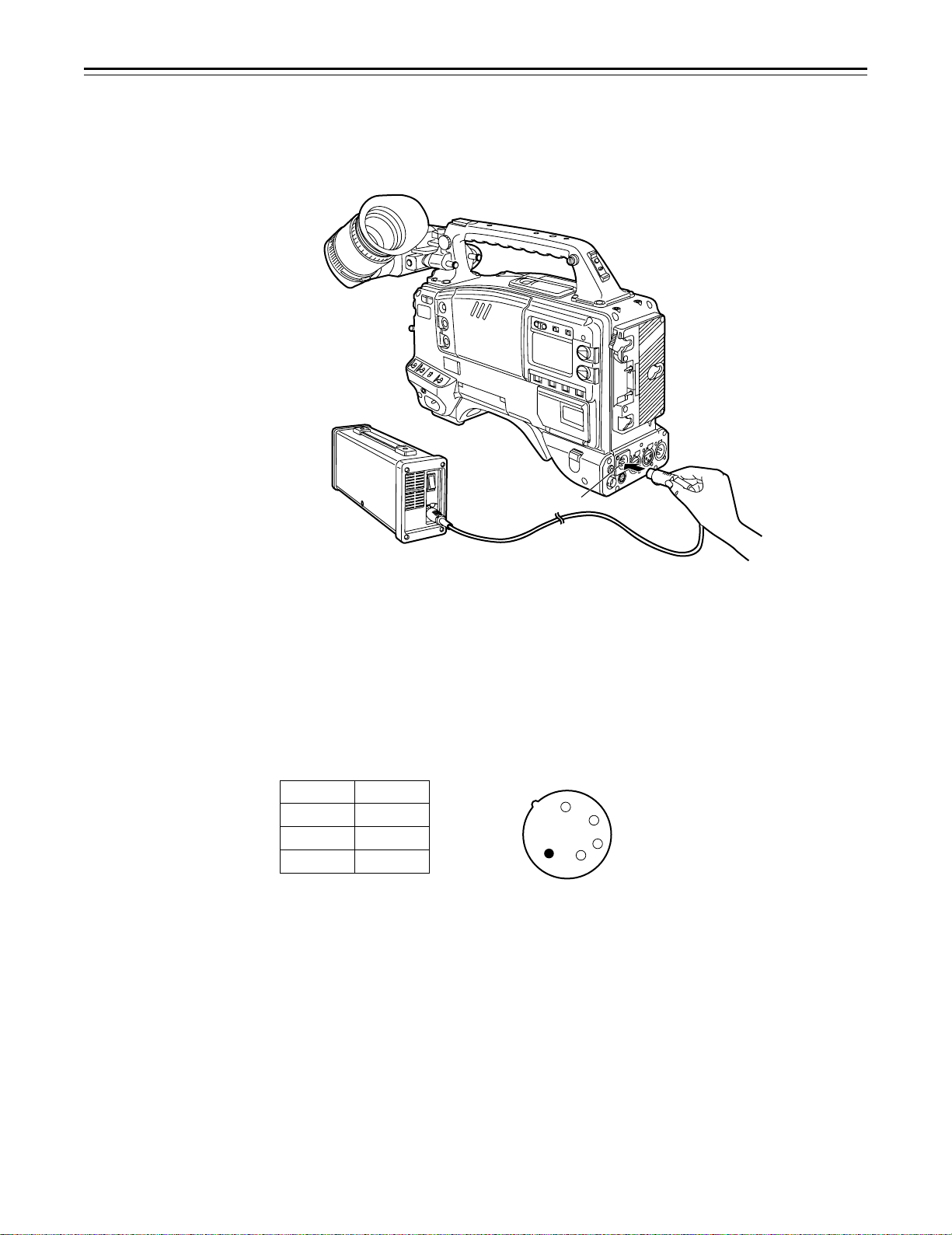
Using an AC Power Supply (When Using the AJ-B75 AC Adaptor)
1 Connect the unit’s EXT DC IN socket with the DC OUT connector of the AJ-B75 AC
adaptor.
DC IN Connector
2 Set the AC adaptor’s power to ON.
3 Set the unit’s power switch to ON.
|Notes{
ÁWhen using an external power supply other than the AJ-B75 AC adaptor, check the pin signal of
the EXT DC IN socket.
ÁWhen both a battery pack and AC adaptor are connected, power is supplied from the AC
adaptor.
ÁWhen using an AC adaptor, the AC adaptor’s power must be set to ON before the unit’s POWER
switch is set to ON. If this sequence is reversed, the AC adaptor’s output voltage will rise slowly
and may cause the unit to malfunction.
Pin No. Signal
1 GND
2, 3 ——
4 o12 V
4
3
2
1
– 28 –
Page 29
Power Supply
Checking and Selecting the Type of Battery
MODE CHECK button
To check the type of battery
HOLD button
MENU/ITEM switch
DOWN button
UP button
1 Press the MODE CHECK button.
While this button is held down, the type of battery is displayed in the remaining battery charge
display area.
The type of battery is displayed here.
NiCd12
NiCd13
NiCd14
IDX L-40
L-60
L-90
ANTON-D
IDX-D
Display seen inside the viewfinder
To select the type of battery
1 When the MENU SET/OFF switch is set to SET while the HOLD button is pressed, the battery
selection menu appears on the screen.
2 Press the SHIFT/ITEM button, and move the arrow (cursor) to BATTERY SEL.
3 Press the UP or DOWN button to select the type of battery.
¢
|{
M
ASTER GA I
W
GA I N
L18O
GA I N
M
I
D
GA I N
I
G
BATT ERY SEL|ECT
BABATTERY SSEL
RR|SEL EECT
L
CO O
CO OR RBAL
N
:
:
:
:
NiC 12
:
0dB
9dB
dBHH
M
P
{
d
T
The type of battery is displayed here.
NiCd12 L-60
{
NiCd13 L-90
NiCd14 ANTON-D
IDX L-40 IDX-D
Display seen inside the viewfinder
– 29 –
Page 30
– 30 –
Page 31

– 31 –
Page 32

– 32 –
Page 33

– 33 –
Page 34

Adjusting the Viewfinder
Adjusting the Position
1 Lift up the viewfinder forward-backward/left/right position clamp lever to release the lock.
2 Adjust the position of the viewfinder in the forward-backward and left-right directions.
Viewfinder
Lever
3 Tighten the viewfinder forward-backward/left-right position clamp lever to the locked position.
– 34 –
Page 35

-3
-3
-2
-1
+1
+2
+3
-2
-1
0
+
1
+
2
+
3
– 35 –
Page 36

Adjusting the Viewfinder (The viewfinder shown in the illustration is the optional AJ-VF10P.)
Detaching the Eyepiece
Detaching the eyepiece allows the entire screen to be seen clearly even when shooting with your
eye removed from the viewfinder. This also facilitates the removal of dust which has adhered to
the CRT screen and mirror.
|Note{
Absolutely do not wipe the mirror surface as it has been specially treated. Dust which has adhered
to the mirror should be blown away with a blower, etc.
1 Press the lock button.
2 Turn the lock ring as far as possible in the counter-clockwise direction and line up the align-
ment marks on the lock ring and viewfinder barrel.
Eyepiece
2
Lock Ring
1
Alignment Marks
Lock Button
3 Detach the eyepiece.
Remounting the eyepiece
1. Line up the alignment marks on the lock ring and the viewfinder barrel, and then insert the
eyepiece.
2. Turn the eyepiece as far as possible in the clockwise direction. The lock button latches with a
clicking sound, and remounting is completed.
– 36 –
Page 37

– 37 –
Page 38

– 38 –
Page 39

Audio Input Preparations
(The viewfinder shown in the illustration is the optional AJ-VF10P.)
Mounting the AJ-MH700P Microphone Holder (Option)
1 Remove the microphone holder mounting screws.
2 Mount the AJ-MH700P microphone adaptor (option) to the main unit.
Mount the microphone
adaptor using the
accessory screws.
3 Mount the microphone to the microphone holder and tighten the screws.
4 Connect the microphone connecting cable to the MIC IN jack.
To the MIC IN Connector
5 Set the AUDIO IN switch to FRONT [MIC] in accordance with the audio channel to be re-
corded.
– 39 –
Page 40

– 40 –
Page 41

– 41 –
Page 42

Mounting the Unit to a Tripod
When mounting the unit to a tripod, use an optional tripod attachment.
1 Mount the tripod attachment (SHAN-TM700) onto the tripod.
Select the attachment hole in consideration of the unit’s and tripod attachment’s center of
gravity. In addition, check that the diameter of the selected hole matches the diameter of the
universal head’s camera mounting screw.
2 Mount the camera to the tripod attachment.
Slide the unit forward along the grooves until a clicking sound is heard.
Tripod Attachment
When detaching the tripod attachment
Hold down the red lever and move the black lever in the direction of the arrow.
Red Lever
|Note{
When the tripod attachment pin does not return to its original position after the camera has been
detached, hold down the red lever and move the black lever in the direction of the arrow again to
return the pin to its original position.
Care should be taken as the camera cannot be mounted if the pin remains in the center.
Black Lever
– 42 –
Page 43

Mounting the Shoulder Belt
Press to open the hook.
Shoulder Belt
To remove the shoulder belt, open the hooks and then remove the belt.
Press
|Note{
When mounting and removing the shoulder belt, press on the top of the hooks to check that the
belt is securely mounted.
–43–
Page 44

Adjusting the Shoulder Pad Position
The shoulder pad can be slid up to 2/5½ in the forward-backward direction from the center position
(the position when shipped from the factory). Adjust the shoulder pad position to facilitate operation of the unit.
1 Loosen the two screws.
2 Slide the pad in the forward-backward direction to select an appropriate position.
3 Tighten the screws to clamp the pad.
Screws
Shoulder Pad
Bottom
– 44 –
Page 45

– 45 –
Page 46

Connecting the AJ-EC3 Extension Control Unit (Option)
Connecting the AJ-EC3 extension control unit (option) allows a portion of the camera section
functions to be operated by remote control.
When the AJ-EC3 is connected and the POWER switches of the unit and AJ-EC3 are set to ON,
the unit automatically enters remote control mode.
The handling instructions included with the AJ-EC3 describe operations for when the AJ-EC3 is
connected to an AQ series digital camera.
When the AJ-EC3 is connected to the AJ-SDC915, some functions differ, and some features
cannot be used.
6-pin Cable
ECU Connector
ECU AJ-
65
∫
1
RB
ECU
AJ-EC3
|Notes{
ÁThe POWER switches of the unit and AJ-EC3 must be set to OFF before the 6-pin cable is
connected or disconnected.
ÁWhen OFF has been set for ECU DATA SAVE on the SUB menu CAMERA SW MODE page
of MAIN menu screen 2 of 4
All adjustments and settings made using the switches and controls on the menu setting section
of the AJ-EC3 are erased when the unit’s POWER switch is set to OFF. Neither is it possible to
save any of the adjustments and settings—except for the menu settings—performed using the
AJ-EC3’s switches and controls on the setup card. However, when the AJ-EC3 is connected
again, these settings return to the AJ-EC3 settings.
(Menu contents set with the menu setting section are saved.)
For use in this mode, set the POWER switch on the AJ-EC3 to the OFF position before the
unit’s POWER switch is set to OFF. If the unit’s POWER switch is set to OFF before the
POWER switch on the AJ-EC3 is set to the OFF position, the adjustments and settings performed when the AJ-EC3 was operated will be saved instead.
ÁWhen ON has been set for ECU DATA SAVE on the SUB menu CAMERA SW MODE page
of MAIN menu screen 2 of 4
The adjustments and settings performed using the switches and controls on the AJ-EC3’s
menu setting area will not be lost even when the unit’s POWER switch is set to the OFF
position.
|Note{
The functions of the AJ-EC3 are limited as follows.
ÁThe STORE switch does not function.
(If the menu settings are changed while the AJ-EC3 is connected to the AJ-SDC915, the new
menu settings are saved automatically as soon as the changes are made.)
Note that the AJ-EC3 gain switch displays p3, 0 and 9 correspond to L, M and H, and the
OUTPUT switch settings CAMERA, TEST and BAR to CAM/AUTO KNEE ON, CAM/AUTO
KNEE OFF and BAR for each main unit.
ÁThe Synchro scan and Super V modes cannot be used while the AJ-EC3 is connected to the
unit.
ÁThe lens iris (IRIS) control of the AJ-EC3 is valid only when the lens iris AUTO/MANUAL selector
is set to AUTO.
– 46 –
Page 47

Displaying Menus on the Viewfinder Screen
Displaying the Setting Menu Inside the Viewfinder
The setting menus are displayed on the viewfinder screen when the MENU SET/OFF switch is set
to the SET position.
There are two types of setting menus, MAIN menus and SUB menus.
Setting menus are displayed in 1-page increments.
All the pages contained in the setting menus and how each page is configured are shown in the
table below.
The menu configuration can be changed to suit a particular objective.
Setting Menu Configuration
MAIN MENU
MAIN MENU 1/4
(See page 108)
MAIN MENU 2/4
(See page 109)
MAIN MENU 3/4
(See page 110)
SUB MENU
ROP (112)
MATRIX (113)
LOW SETTING (114)
MID SETTING (115)
HIGH SETTING (116)
ADDITIONAL DTL (117)
SKIN TONE DTL (118)
KNEE/LEVEL (119)
FLARE/GAMMA (120)
CAMERA SETTING (120)
VF DISPLAY (121)
VF INDICATOR (123)
CAMERA ID (124)
SHUTTER SPEED (124)
SYNCHRO SCAN (125)
!LED (125)
CAMERA SW MODE (126)
SUPER GAIN (127)
VTR FUNCTION (128)
BATT/TAPE ALARM (130)
CARD READ/WRITE (131)
CARD R/W SELECT (132)
REC (ASPECT)/PB/RET (133)
MIC/AUDIO (134)
GENLOCK/IRIS (136)
VIDEO OUT (137)
TIME/DATE (137)
LENS SEL/ADJ (137)
MAIN MENU 4/4
(See page 111)
REMOTE
(See page 147)
USER MENU SEL 1/3 (138)
USER MENU SEL 2/3 (139)
USER MENU SEL 3/3 (140)
AUTO SHADING (141)
EVALUATION (141)
INITIALIZE (146)
DIAGNOSTIC (146)
VF IND. (REMOTE) (147)
!LED (REMOTE) (148)
TALLY/RET (148)
The figures in parentheses are reference pages.
– 47 –
Page 48

Displaying Menus on the Viewfinder Screen
Checking and Selecting the Master Gain Setting
1 The menu shown in the figure below is displayed when the MENU SET ON/OFF switch is set
to SET while the HOLD button is held down.
2 The current low, mid and high gain settings are displayed.
3 Press the SHIFT/ITEM button, and move the arrow (cursor) to the LOW, MID or HIGH GAIN
menu item.
4 Set the gain by pressing the UP or DOWN button. Any value from p3 dB to o30 dB can be
set.
¢
|{
M
ASTER GA I
LO
W
GA I N
D
GA I N
M
I
HH
G
GA I N
I
BATT ERY SEL|ECT
BABATT ERY SSEL
CO O
RR|SEL EECT
L
CO OR RBAL
N
:
:
:
:
NiC 12
:
0dB
9dB
dB18
P
M
{
d
{
T
– 48 –
Page 49

Displaying Menus on the Viewfinder Screen
Selecting the Color Bar Setting
1 The menu shown in the figure below is displayed when the MENU SET ON/OFF switch is set
to SET while the HOLD button is held down.
2 To select the color bar menu item, press the SHIFT/ITEM button, and move the arrow (cur-
sor) to COLOR BAR.
3 Select the color bar setting by pressing the UP or DOWN button. The SMPTE or SNG setting
can be selected.
|
M
ASTER GA I
LO
W
GA I N
D
GA I N
M
I
HH
G
GA I N
I
BATT ERY SEL|ECT
BABATT ERY SSEL
CO O
RR|SEL EECT
L
¢
CO OR RBAL
{
N
:
:
:
:
NiC 12
:
M
0dB
9dB
dB18
{
P
d
{
T
– 49 –
Page 50

Displaying Menus on the Viewfinder Screen
Checking the DIAGNOSTIC Screen Setting
1 Set the MENU SET ON/OFF switch to SET while the HOLD button is held down.
2 Press the PAGE button.
3 The menu screen shown in the figure below appears, and it is now possible to check the
DIAGNOSTIC screen settings.
4 To close the menu screen, return the MENU SET ON/OFF switch to OFF.
O
OPER AT I ON
DRUM RUNN I NG
THREAD I NG
VTR SYSCON
CAM
DAT ROMA
DV Ve r .
DIAGNOSTIC
SYSCON
:
00000 1
:
00000 10
:
00000 10
O
Ve r P
O
Ve r . .
tttt
O
Ve r .
tt
O
ttt
tt tt tt
N
t
t
t
.
ttt
N
N
..
0
h
h
N
N
– 50 –
Page 51

Displaying Menus on the Viewfinder Screen
Changing the setting menu configuration
The setting menu can be configured by selecting only the pages necessary for the application.
Pages are selected using the MENU SELECT page of the engineer menu mode.
When using the engineer menu, switch the unit to engineer mode as described below.
The unit is switched to user mode by setting the MENU SET/OFF switch to “SET”.
The unit is switched to engineer mode by holding down the SHIFT/ITEM and UP buttons simultaneously and setting the MENU SET/OFF switch to SET.
The user and engineer modes differ as follows.
User mode: Only the selected pages the setting menu can be used. The data set on each
page is written to the non-volatile memory, allowing it to be stored for extended periods of time.
Engineer mode: All pages contained in the setting menu can be used. In addition, the data set
at each page is written to the non-volatile memory, allowing it to be stored for
extended periods of time.
If, upon completion of the adjustments and settings in the engineer mode, the menu is set to be
configured only with the frequently used pages, the pages which are often needed can be called
promptly.
(Select the method using the user menu selection procedure described on pages 138 to 140.)
|Note{
The engineer menu will always open if the AJ-EC3 extension control unit (optional accessory) is
connected to the unit and the unit is operated from an external source.
Transferring to the MAIN menus and SUB menus
UP/
DOWN
button
SUB MENUMAIN MENU 1/4
PAGE
button
PAGE button
MAIN MENU 2/4
PAGE button
MAIN MENU 3/4
PAGE button
MAIN MENU 4/4
PAGE button
SUB menu
ÁPress the SHIFT/
ITEM button to select
the items.
ÁPress the UP and
DOWN buttons to
select the settings.
ÁTo select a page in a SUB menu, first move to the MAIN menu and then select the desired SUB
menu.
ÁChanges are made to the settings on the SUB menus.
– 51 –
Page 52

Displaying Menus on the Viewfinder Screen
Basic Setting Menu Operations
The setting menu is operated using the MENU SET/OFF switch and the SHIFT/ITEM, UP, DOWN
and PAGE buttons.
SHIFT/ITEM Switch
UP Button
DOWN Button
PAGE Button
SHIFT/
PAGE
ITEM
UP
DOWN
SET
OFF
MENU
F-RUN
SET
R-RUN
CH 1
MIX
CH 2
TCG
CUE
FRONT
REAR
CH 1 CH 2
REAR MIC POWERREAR MIC POWER
AUDIO IN
MIC
MIC
LINE
ON
OFF
MENU SET/OFF Switch
To display a SUB menu directly (user mode)
1 Set the MENU SET/OFF switch to the SET position.
The status displays at the top and bottom of the viewfinder screen are cleared, and the page
on which the previous setting menu operation was completed now appears on the screen.
When a menu is used for the first time, the page with the lowest number among the selected
pages appears on the screen.
¢
|
{
ROP
MAS T E R
MAS T E R
MAS T E R
RGAIN
GA I NB
R PEDEST AL
PEDES TAL
G
PEDES TAL
B
:
PED µ 000
:
:
:
:
:
:
:
µ 00
.045
µ 000
µ 000
µ 000
µ 000
µ
000
DTL
GAMMA
To display a MAIN menu directly (engineer mode)
1 Set the MENU SET/OFF switch to the SET position while the SHIFT/ITEM button and UP
button are held down together.
MAIN menu screen 1 of 4 now appears.
MA I N ME NU 1 / 4
EE¢EE EEEE
ROP
MA TR I X
W
SETT I NG
LO
SETT I NG
MID
SETT I NG
HIGH
ADDITIONAL DTL
KNEE / LEVE L
FLARE/ GAMMA
CAMERA
The pages can also be selected using the UP and DOWN buttons in combination with the PAGE
button as indicated below.
ÁPAGEµUP: When the UP button is pressed while the PAGE button is held down, opera-
ÁPAGEµDOWN: When the DOWN button is pressed while the PAGE button is held down, oper-
DTLSK I N TONE
SETT I NG
tion advances to the next menu and the menu next to it and so on for as long
as the button is held down.
ation is returned to the previous menu and the menu before it and so on for as
long as the button is held down.
– 52 –
Page 53

Displaying Menus on the Viewfinder Screen
To select a MAIN menu page
1 Press the PAGE button to select a particular MAIN menu.
Each time the button is pressed, the MAIN menu screen is advanced by one page
(1>2>3>4>1>, etc.).
EE¢EE
MA I N ME NU 1 / 4
ROP
MA TR I X
W
SETT I NG
LO
SETT I NG
MID
SETT I NG
HIGH
ADDITIONAL DTL
KNEE / LEVE L
FLARE/ GAMMA
CAMERA
DTLSK I N TONE
SETT I NG
EEEE
PAGE button
MA I N ME NU 2 / 4
EE¢EE EEEE
VFVFDISPLAY
INDICATOR
CAMERA
SHUTTER SPEED
SYNCHRO SCA N
!LED
CAMERA
SUPER GA I N
VT R FUNC T I ON
BATT / TAPE ALARM
ID
S
W
MODE
To transfer from a MAIN menu to a particular SUB menu
1 Press the SHIFT/ITEM button.
When this button is pressed, the cursor (arrow) indicating the selected item moves to the
SUB menu.
¢
MA I N ME NU 1 / 4
EE
EE EEEE EEEE EEEE
ROP
MA TR I X
W
SETT I NG
LO
SETT I NG
MID
SETT I NG
HIGH
ADDITIONAL DTL
KNEE / LEVE L
FLARE/ GAMMA
CAMERA
DTLSK I N TONE
SETT I NG
SHIFT/ITEM button
MA I N ME NU 1 / 4
¢
ROP
MA TR I X
W
SETT I NG
LO
SETT I NG
MID
SETT I NG
HIGH
ADDITIONAL DTL
KNEE / LEVE L
FLARE/GAMMA
CAMERA
DTLSK I N TONE
SETT I NG
2 Press the UP or DOWN button.
Operation is now switched to the selected SUB menu.
¢
|
{
ROP
MAS T E R
MAS T E R
MAS T E R
RGAIN
GA I NB
R PEDEST AL
PEDES TAL
G
PEDES TAL
B
PED
DTL
GAMMA
:
:
:
:
:
:
:
:
µ 000
µ 00
.045
µ 000
µ 000
µ 000
µ 000
µ
000
To transfer from a SUB menu to the MAIN menu
1 Press the PAGE button.
Operation moves to the MAIN menu.
¢
|
ROP
MAS T E R
MAS T E R
MAS T E R
RGAIN
R PEDEST AL
G
B
PED
DTL
GAMMA
GA I NB
PEDES TAL
PEDES TAL
{
:
p
003
:
µ 00
:
.045
:
µ 000
:
:
:
:
µ 000
µ 000
µ 000
µ
000
PAGE button
MA I N ME NU 1 / 4
EE¢EE EEEE
ROP
MA TR I X
W
SETT I NG
LO
SETT I NG
MID
SETT I NG
HIGH
ADDITIONAL DTL
KNEE / LEVE L
FLARE/GAMMA
CAMERA
SETT I NG
DTLSK I N TONE
– 53 –
Page 54

Displaying Menus on the Viewfinder Screen
SHIFT/
ITEM
PAGE
UP
DOWN
MENU
CH 1 CH 2
TCG
SET
OFF
F-RUN
SET
R-RUN
MIC
MIC
AUDIO IN
LINE
ON
OFF
FRONT
REAR
CUE
CH 1
MIX
CH 2
REAR MIC POWERREAR MIC POWER
Operations on SUB menus
Selecting the desired item
1 Press the SHIFT/ITEM button.
Each time this button is pressed, the cursor (arrow) which indicates the selected item moves
to the next item.
Cursor
Movement order
The item can also be selected using the UP and DOWN buttons as follows.
Changing the settings
Press the UP button to increase the setting.
ÁThe setting is incremented by 1 level each time
the UP button is pressed.
Press the DOWN button to decrease the setting.
ÁThe setting is decremented by 1 level each time
the DOWN button is pressed.
†
STER
MA
MAST E R
MAST E R
RGAIN
GA I NB
RPEDESTAL
PEDESTAL
G
PEDESTAL
B
¢
|
ROP
PED
DTL
GAMMA
{
:
:
:
:
:
:
:
:
µ 000
µ 00
.045
µ 000
µ 000
µ 000
µ 000
µ
000
Changing the ON/OFF selection
The setting switches to ON or OFF each time the UP (or DOWN) button is pressed.
Returning to the default settings
Align the arrow with READ FACTORY DATA on the “INITIALIZE” SUB menu page of the MAIN
menu screen 4 of 4.
When the UP (or DOWN) button is now pressed, the initial (factory) settings will be restored.
However, care should be taken as the camera ID cannot be returned to the default settings.
Quitting the menu
Set the MENU SET/OFF switch to OFF.
ÁThe setting menu disappears from the viewfinder screen and the displays indicating the unit’s
current status appear at the top and bottom of the viewfinder screen.
– 54 –
Page 55

Lamp Displays Inside the Viewfinder
The viewfinder displays are as follows.
1. REC (recording) lamp
This lamp lights (red) during recording, and flashes when warnings are issued.
ÁSee “Warning System” (page 149, 150) for a detailed description.
2. BATT (battery) lamp
When the battery voltage has dropped, this lamp begins flashing several minutes before the
unit can no longer be operated, and lights when the unit can no longer be operated.
To prevent operation from being interrupted, exchange the battery quickly before the battery
runs out.
ÁSee “Warning System” (page 150) for a detailed description.
3. ! (irregular operation status warning) lamp
This lamp lights when the unit enters irregular operation status for any of the items set to ON at
the ! LED page of the setting menu. Applicable items are as follows.
3
1
REC
!
BATT
5
50
VTR SAVE
42
Setting item Setting contents
Gain (0 dB)
Gain (p3 dB)
SHUTTER switch
WHITE PRESET switch
Lens extender
Filter control
SUPER V switch
25M/50M
ÁSee “Setting the ! Lamp Display” (next page) for selecting ! lamp display items.
4. VTR SAVE (VTR power saving) lamp
This lamp lights when the VTR SAVE/STBY switch is set to SAVE. It is not lighted during
recording.
5. 50 (50Mbps recording/playback) lamp
This lamp lights when the mode for recording at 50 Mbps is selected and when a tape is played
back at 50 Mbps.
|Note{
The SAVE status is automatically established and the lamp lights regardless of the VTR SAVE/
STBY switch position at the time set by the pause timer (pause time) when the unit is in the
recording pause mode or when 2 minutes have elapsed since the unit was placed in the playback
pause mode.
The gain is set to a value other
than 0 dB.
The gain is set to a value other
than p3 dB.
The switch is set to ON.
The switch is set to PRESET.
The lens extender is being used.
The control is set to a value
other than 1.
The switch is set to ON.
Lamp lights when the 25 or
50 Mbps recording format is set.
– 55 –
Page 56

Lamp Displays Inside the Viewfinder
Setting the ! Lamp Display
The items subject to the ! lamp display are selected on the “! LED” SUB menu page on the MAIN
menu screen 2 of 4. (Under the factory setting, the “! LED” page is not displayed.) To perform
operations on the “! LED” page, either switch the unit to the engineer mode or select the “! LED”
page on the USER MENU SEL page 2 of 3 on the MAIN menu screen 4 of 4.
ÁFor details on selecting the engineer mode and display page, refer to Setting Menu Configura-
tion (page 51).
1 Set the MENU SET/OFF switch to the SET position while the SHIFT/ITEM button and UP
button are held down together.
2 Press the PAGE button to display the MAIN menu screen 2 of 4.
3 Repeatedly press the SHIFT/ITEM button to move the cursor to the “! LED” position.
4 Press the UP or DOWN button to open the ! LED page.
¢
|
GA I N(0dB
GA I N(3dB
∂
SHUTT ER
W
H I TE PRESET
EXTENDER
FILTER
SUPER V
25M/50M
GAIN (0 dB): This selects whether the ! lamp is to light when the gain is set to a value other than
GAIN (¶3 dB): This selects whether the ! lamp is to light when the gain is set to a value other than
SHUTTER: This selects whether the ! lamp is to light when the SHUTTER switch is set to the
WHITE PRESET: This selects whether the ! lamp is to light when the white balance memory channel is
EXTENDER: This selects whether the ! lamp is to light when the lens is in the EXTENDER mode.
FILTER: This selects whether the ! lamp is to light when the filter is set to a position other than
SUPER V: This selects whether the ! lamp is to light when SUPER V is set to ON.
25M/50M: This selects whether the ! lamp is to light when the recording format is set to
{
!LED
)
:
O
)
:
OFNF
:
OOFN
:
F
:
OOFN
:
F
:
OFF
:
OFF
0 dB.
p3 dB.
ON position.
set to PRST.
3200K and CLEAR. (1)
25 Mbps or 50 Mbps.
5 Repeatedly press the SHIFT/ITEM button to move the cursor to the position of the desired
item.
6 Press the UP or DOWN button at the selected item to select whether the ! lamp is to be set
ON or OFF.
To select ON: Press the UP button.
To select OFF: Press the DOWN button.
To select ON or OFF for another item, repeat steps 5 and 6.
7 When the menu operations are completed, return the MENU SET/OFF switch to the OFF
position.
The setting menu is cleared from the viewfinder screen, and the unit’s current statuses appear at the top and bottom of the viewfinder screen.
– 56 –
Page 57

Status Displays Inside the Viewfinder Screen
In addition to images, messages indicating the unit’s settings and operating status appear on the
viewfinder screen. The center marker and safety zone marker, etc. are also displayed.
When the MENU SET/OFF switch is set to OFF, items set to SET at the VF DISPLAY page of the
setting menu and using related switches appear at the top and bottom of the screen.
Messages informing of the setting contents or of the adjustment course or results can also be
displayed for approximately 3 seconds when settings are changed, during the course of adjustments, or after adjustments have been completed.
ÁSee “Selecting Display Items” (page 60) for selecting display items, “Display Mode and Setting
Change Message” (page 61) for the setting change message, and “Setting the Marker Displays”
(page 62) for the marker displays.
The display positions of all items which can be displayed are shown in the figure below.
e Extender display
f Shutter speed/mode display
g Remaining tape length display
h Remaining battery level display
i Filter display
j White balance memory display
k Gain value display
l Audio level display
m Iris value display
n Warning display
o Safety zone marker
p Center marker
q Super iris ON or super black ON display
r MARK1/MARK2/TAKE display
s TCG (Time Code Generator) display
t Master gain & super gain setting display
u 50M display
v Battery setting display
1 2 q 3 s 4
1/250 30-25 14.6V
EX2
o
t
S
o
50M
NiCd12
u
v
p
n
o
1 A 0dB F5.6
-------
T_M1
r
o
5 6 7 8 9
|Note{
When in SUPER V mode, “SUP.V” is displayed at shutter speed position f in the Viewfinder
screen.
– 57 –
Page 58

Status Displays Inside the Viewfinder Screen
1 Extender display
This is displayed when the lens extender is being used.
2 Shutter speed/mode display
This displays the shutter speed or shutter mode setting.
OFF (OFF is not displayed.):
The shutter is not used.
1/100, 1/120, 1/250, 1/500, 1/1000, 1/2000:
Shutter speeds (seconds) during standard mode.
1/60.8–1/250 (SYNCHRO SCAN):
Synchro scan mode is selected.
SUPER V: High vertical resolution mode is selected.
3 Remaining tape length display
This indicates the remaining tape length (minutes) for the VTR during recording.
Remaining tape length display
(25 Mbps)
Remaining tape length display
(50 Mbps)
Display
F–60
60–55
55–50
50–45
45–40
40–35
35–30
30–25
25–20
20–15
15–10
10–5
5–0
Remaining tape
length
Full to 60 minutes
60 to 55 minutes
55 to 50 minutes
50 to 45 minutes
45 to 40 minutes
40 to 35 minutes
35 to 30 minutes
30 to 25 minutes
25 to 20 minutes
20 to 15 minutes
15 to 10 minutes
10 to 5 minutes
5 to 0 minutes
Display
F–30
30–25
25–20
20–15
15–10
10–5
5–0
The “5–0” display flashes when there is
less than 2 minutes of tape remaining.
Remaining tape
length
Full to 30 minutes
30 to 25 minutes
25 to 20 minutes
20 to 15 minutes
15 to 10 minutes
10 to 5 minutes
5 to 0 minutes
4 Remaining battery level display
When an Anton Bauer Digital Magnum Series battery is used to supply power to the unit, the
remaining battery level is displayed numerically (%).
|Note{
When a Digital Magnum series battery made by Anton Bauer is used to supply external
power to the unit near the battery end, the remaining battery level display will show the
external voltage, and the unit will be operated by the external power supply.
5 Filter display
This displays the type of filter selected.
6 White balance memory display
This displays the selected white balance automatic adjustment memory.
A: The WHITE BAL switch is set to A.
B: The WHITE BAL switch is set to B.
P: The WHITE BAL switch is set to PRST.
7 Gain value display
This displays the image amplifier gain setting (dB) set by the GAIN switch.
– 58 –
Page 59

Status Displays Inside the Viewfinder Screen
8 Audio level display
This displays the audio CH1 level.
During sine wave input, the audio level display corresponds roughly to the VTR level meter
display as follows.
Audio Channel 1 Level Display
VTR Level Meter
-40 -30 -25 -20 -15 -10 -5 0
9 Iris value display
This displays the approximate iris setting (F number).
10 Warning display
This displays the black balance, white balance, auto knee function, super iris, super gain
and other warning displays.
11 Safety zone marker
This indicates the safety zone to be the 80% or 90% (factory setting) range of the viewfinder
screen area.
The ratio of this area to the total screen area is selected on the VF DISPLAY page of the
setting menu.
ÁRefer to “Setting the Marker Displays” (page 62) for further details.
12 Center marker
This indicates the center of the viewfinder screen.
The marker appears when its display is set to ON on the VF DISPLAY page of the setting
menu.
13 Super iris ON display
This indicates that the super iris is ON.
14 MARK1/MARK2/TAKE display
If the MARK switch is pressed while the Picture Link function is used, M1 or M2 appears to
indicate the significance of the information concerned.
Nothing will appear if this function is not required.
Alternatively, T_ (TAKE) appears when the RET switch of the lens is used as the TAKE
function.
E
15 TCG display
This displays the time code generator value.
16 Master gain & super gain setting display
When the MODE CHECK button is pressed, the current GAIN L/M/H and SUPER GAIN
settings are displayed.
17 50M display
When the MODE CHECK button is pressed, this display appears when the recording format
has been set to 50 Mbps.
18 Battery setting display
This indicates the type of the battery currently being used.
1) Iris value display
The iris value is displayed when using a lens with the iris value display function.
– 59 –
Page 60

Status Displays Inside the Viewfinder Screen
Selecting Display Items
The items which are to be displayed on the viewfinder screen can be selected by setting ON or
OFF for each item on the VF INDICATOR page. The items which can be selected are as follows.
ÁExtender display
ÁShutter speed/mode display
ÁRemaining tape length display
ÁRemaining battery level display
ÁFilter display
ÁWhite balance memory display
ÁGain value display
ÁLevel meter display
ÁIris value/super iris ON status display
ÁCamera ID display
ÁThe camera ID is displayed when recording the color bar according to the OUTPUT/AUTO
KNEE switch setting. See “Setting the Camera ID” (page 63) for a detailed description.
Select the items to be displayed on the viewfinder screen.
1 Set the MENU SET/OFF switch to the SET position while the SHIFT/ITEM button and UP
button are held down together.
2 Press the PAGE button to display the MAIN menu screen 2 of 4.
3 Press the SHIFT/ITEM button to move the cursor to the “VF INDICATOR” position.
4 Press the UP or DOWN button to open the VF INDICATOR page.
Extender display
Shutter speed/mode display
Remaining tape length display
Remaining battery level display
Filter display
White balance memory display
Gain value display
Level meter display
Iris value/super iris ON status display
Camera ID display
DATE/TIME display
>
ON
EXTENDER
SHUTT ER
TAPE
BAT TERY
FILTER
WH I TE
GA I N
LEVEL METER CH1
CAMERA I D
INDICATOR
VF
IRIS S IRIS
:
ON
:
ON
:
ON
:
ON
:
ON
:
ON
:
ON
:
:
r
:
ON
:
OFDATE/ T MEIF
5 Press the SHIFT/ITEM button to move the cursor to the position of the disired item.
6 Press the UP and DOWN buttons to choose whether to display (ON) or not display (OFF) the
selected item on the viewfinder screen.
The setting switches to ON or OFF each time the UP (or DOWN) button is pressed.
Repeat steps 5 and 6 when setting display ON/OFF for other items.
7 When menu operations have been completed, set the MENU SET/OFF switch to OFF.
The setting menu disappears from the viewfinder screen and the displays indicating the settings of the selected items appear.
– 60 –
Page 61

Status Displays Inside the Viewfinder Screen
Display Mode and Setting Change Message
Messages informing of the contents of changed settings and adjustment results can be limited to
part of the displayed items or not displayed for all items.
The conditions under which messages are displayed and the corresponding display modes are
shown in the table below.
Setting change/adjustment results messages and display modes
Conditions under which
messages are displayed
When the filter selection is
changed.
When the gain setting is
changed.
When the WHITE BAL switch
setting is changed.
When the OUTPUT/AUTO
KNEE switch is set to AUTO
KNEE or OFFF)
When the shutter speed/
mode setting is changed.
When the white balance is
adjusted (AWB)
When the black balance is
adjusted (ABB)
F) The message is displayed for approximately 3 seconds immediately after the power for the unit is
turned on.
Filter: n (nr1, 2, 3, 4)
GAIN: n dB (nrp3, 0, 3, 6, 9, 12, 15, 18,
GAIN: 21, 24, 30, 36)
WHITE: n (nrACH, BCH, PRESET)
AUTO KNEE: ON (or OFF)
SS: 1/100 (or 1/120, 1/250, 1/500,
SS: 1/1000,1/2000, S. SCAN, SUPER V)
Ex.) AWB: OK
ÁSee “Adjusting the White Balance”
(page 70) for a detailed description.
Ex.) ABB: OK
ÁSee “Adjusting the Black Balance”
(page 75) for a detailed description.
Message
Display mode
setting
1
2
3
q
q
¿
q
q
¿
q
q
¿
q
¿
¿
q
¿
¿
q
¿
¿
q
¿
¿
¿: Message displayed
q: Message not displayed
|Note{
Whether a message is displayed or not also depends on the status of other menu settings.
For instance, even if the filter selection is set to “1”, the filter message will appear if FILTER is set
to ON on the VF INDICATOR page.
– 61 –
Page 62

Status Displays Inside the Viewfinder Screen
Changing the Display Mode
The display mode setting appears on the “VF DISPLAY” SUB menu page of MAIN menu screen
2 of 4.
1 Set the MENU SET/OFF switch to the SET position while the SHIFT/ITEM button and UP
button are held down together.
2 Press the PAGE button to display the MAIN menu screen 2 of 4.
3 Press the SHIFT/ITEM button to move the cursor to the “VF DISPLAY” position.
4 Press the UP or DOWN button to open the VF DISPLAY page.
¢
|
DISP
DISP
SAFETY ZONE 3
CENTER MARK ON
VVF
OUT
VF DTL
ZEBRA1
ZEBRA2
ZEBRA2
50M INDICATION ON
W
LL LLO
5 Press the SHIFT/ITEM button to move the cursor to the “DISP MODE” position.
6 Press the UP (or DOWN) button to switch to the desired display mode.
7 When the menu operations are completed, set the MENU SET/OFF switch to the OFF
position.
The setting menu is cleared from the viewfinder screen, and the unit’s current statuses appear at the top and bottom of the viewfinder screen.
Setting the Marker Displays
ON or OFF is selected for the center mark and safety zone mark display and a ratio of 80% or
90% of the total screen area is set for the safety zone range on the “VF DISPLAY” SUB menu
page of MAIN menu screen 2 of 4.
1 Perform steps 1 to 4 under “Changing the Display Mode” described above so that the VF
DISPLAY page appears on the viewfinder screen, and align the cursor with SAFETY ZONE
or CENTER MARK.
VF D I SPLAY
CONDITION
MODE 3
DETECT 070
DETECT 085
GH
IT
:
:
:
:
:
:
:
:
:
:
:
{
NORMA L
Y
2
%
%
SPOT
45
%
2 Press the UP (or DOWN) button to switch to the desired display mode.
3 When the menu operations are completed, set the MENU SET/OFF switch to the OFF
position.
The setting menu is cleared from the viewfinder screen, and the unit’s current statuses appear at the top and bottom of the viewfinder screen.
– 62 –
Page 63

Status Displays Inside the Viewfinder Screen
Setting the Camera ID
The camera ID can be set at the CAMERA ID page of the setting menu.
A camera ID of up to ten characters including English letters, symbols and spaces can be used.
The camera ID is recorded when the OUTPUT/AUTO KNEE switch is set to BARS and the color
bar signal is being recorded. It is also displayed on the viewfinder screen.
|Note{
When the setting menu is displayed, the camera ID is not displayed even if the color bar signal is
output.
1 Set the MENU SET/OFF switch to the SET position while the SHIFT/ITEM button and UP
button are held down together.
2 Press the PAGE button to display the MAIN menu screen 2 of 4.
3 Press the SHIFT/ITEM button to move the cursor to the “CAMERA ID” position.
4 Press the UP or DOWN button to open the CAMERA ID page.
¢
|
CAMERA I D
:
EEEEEEE EEE
ID
{
: The cursor is moved to the right (max. 10 spaces) by the
SHIFT/ITEM button.
: Alphanumerics, symbols and spaces are selected by the
UP and DOWN buttons.
5 Keep pressing the UP (or DOWN) button until the character to be set appears.
Each time the UP button is pressed, the character display changes in the following order:
space (Å)¢english letters (A to Z)¢numbers (0 to 9)¢symbols (space, {, |, ), (, ’, ‘, ,, --,
_ , x, /, !). Pressing the DOWN button changes the character display in the reverse order.
6 Press the SHIFT/ITEM button to move the cursor to the next position, and return to step 5 to
set the characters.
7 When the menu operations are completed, set the MENU SET/OFF switch to the OFF
position.
The setting menu is cleared from the viewfinder screen, and the unit’s current statuses appear at the top and bottom of the viewfinder screen.
|Note{
When CAMERA ID on the VF INDICATOR page has been set to ON, the above camera ID setting
will be recorded along with the color bars.
– 63 –
Page 64

Displays
Remaining Battery Level and Audio Level Displays
Remaining tape length
When the amount remaining
on the tape is more than
21 minutes long, all seven
segments up to the “F” position
appear lighted.
When it is less than 21 minutes
long, one segment will go off
for every 3-minute reduction in
the length.
DF
SLAVE TCG HOLD WIDE
h min s frm
E TAPE F
E BATT F
Remaining battery level
When the digital display (%
display) battery is used, the 7
segments light up all the way
to the “F” position if the remaining battery level is more than
70%.
If the remaining battery level is
under 70%, one of the segments goes off for each further
10% reduction in the remaining
level.
RF
SERVO
HUMID SLACK
VTR Section Operation/Status-Related Displays
EMPHASIS
0
10
20
30
40
CH1 CH2
dB
Audio CH level meter
Lights
DF
SLAVE
TCG
HOLD
WIDE
Error code:
Indicated in the display
window.
Warning display
RF: Lights when video head clogging occurs.
SERVO: Lights when the servo is out of order.
HUMID: Lights when condensation occurs on the head drum.
SLACK: Lights when tape wind-up trouble occurs.
ÁSee “Warning System” (page 149) for a detailed description.
DF
SLAVE TCG HOLD
WIDE
h min s frm
E TAPE F
E BATT F
RF
SERVO
HUMID SLACK
EMPHASIS
0
10
20
30
40
CH1 CH2
dB
– 64 –
Page 65

Displays
Time Code-Related Displays
DF
SLAVE TCG HOLD
WIDE
h min s frm
E TAPE F
E BATT F
RF
SERVO
These lamps light to indicate the time code, CTL and real time displays.
DF: This lamp lights during drop frame mode
SLAVE: This lamp lights when the time code is locked to an external source.
HOLD: This lamp lights when the time code generator is held (when the HOLD button is pressed).
WIDE: This lamp lights when a tape is recorded or played back with an aspect ratio of 16:9.
Time counter display: This displays the time code, CTL, user bit and real time.
ÁSee below for the relationship between displayed items and switch settings.
Relationship between the TCG and DISPLAY switch setting positions and the time counter
display
The item displayed in the time counter display is determined by the TCG switch and DISPLAY
switch settings.
Time code-related switch settings and display items
HUMID SLACK
EMPHASIS
0
10
20
30
40
CH1 CH2
dB
TCG switch
position
SET
F-RUN or R-RUN
DISPLAY switch
position
TC or CTL
UB
CTL
TC
UB
Displayed item
Time code
User bit
CTL
Time code
User bit
– 65 –
Page 66

Adjusting the Time and Date
Adjustment and Setup Using the Setting Menu
1 Set the MENU SET/OFF switch to the SET position while the SHIFT/ITEM button and UP
button are held down together.
2 Press the PAGE button to display the MAIN menu screen 3 of 4.
3 Press the SHIFT/ITEM button to move the cursor to the “TIME/DATE” position.
4 Press the UP or DOWN button to open the TIME/DATE page.
:
:
:
:
:
{
99
SET
¢
|
TIME/DATE
YEAR
MONTH 0 1
DAY 0 1
HOUR 0 0
MINUTE 00
»
TIME/DATE
5 Press the SHIFT/ITEM button to select the item to be changed.
6 Press the UP (or DOWN) button to change the setting value.
The number is incremented by o1 each time the UP button is pressed and decremented by
p1 each time the DOWN button is pressed.
:
:
:
:
:
{|
99
SET
TIME/DATE
YEAR
MONTH 0 1
DAY 0 1
HOUR 0 0
¢
MINUTE 00
»
TIME/DATE
7 When the settings have been completed, press the SHIFT/ITEM button to select TIME/DATE
SET and then press the UP (or DOWN) button. The time starts from when the button is
pressed.
TIME/DATE»SET
8 When menu operations have been completed, set the MENU SET/OFF switch to OFF.
The setting menu disappears from the viewfinder screen and the displays indicating the unit’s
current status appear at the top and bottom of the viewfinder screen.
|Note{
The seconds cannot be set and always start from 0 seconds.
– 66 –
Page 67

Adjustments and Setup During Recording
Adjustments and Setup Using the Setting Menu
Adjustments and setup operations during recording are performed at the setting menu.
Setting menu operations are basically performed according to the procedures described on
page 52.
However, these procedures vary slightly according to the item.
Items which can be adjusted or set up at the setting menu are as follows.
Adjustment/setup items at the setting menu
Adjustment/setup item
Setting the gain selector value
Selecting the shutter speed/
mode to be used
Setting the synchro scan mode
shutter speed
Selecting the required VTR
functions
Shading adjustment
Setup card data operations
Page name
SETTING
(LOW/MID/HIGH)
SHUTTER SPEED
SYNCHRO SCAN
VTR FUNCTION
AUTO SHADING
SET UP CARD
Operation reference
Setting the Gain Selector
Value, Setting the DTL and
gamma, etc.
Setting the Electronic
Shutter
Setting the Electronic
Shutter
Selecting Functions
Shading Adjustment
Setup Card Operations
–67–
Page 68

Adjustments and Setup During Recording
Setting the Gain Selector Value
When shooting in locations without sufficient brightness, bright images can be obtained by raising
the gain. However, care should be taken as raising the gain also increases the noise.
The gain value for the image amplifier is selected by the GAIN switch. The gain values corresponding to the L, M and H positions of the GAIN switch are set at the MASTER GAIN page of the
setting menu.
Setting the gain selector value
1 Set the MENU SET/OFF switch to the SET position while the SHIFT/ITEM button and UP
button are held down together.
2 Press the PAGE button to display the MAIN menu screen 1 of 4.
3 Press the SHIFT/ITEM button to move the cursor to the position of the setting page on which
the gain is to be set.
4 Press the UP or DOWN button to open the setting page.
¢
|
LOW SET T I NG
MAST E R
»
H.DTL
.DTL
V10
DTL
H.DTL
DARK 0 0
LEVE L
MAST E R
»
BL ACK STRE TCH OF F
ATRI X
»
GA I N
LEVE L
LEVE L
COR ING 0 3
FREQ. 0 3
DTL
DEPEND . 0 0
GAMMA 0 . 4 5
TABLE AM
:
:
:
:
:
:
:
:
:
:
{
0dB
10
5 Press the SHIFT/ITEM button to move the cursor to the “MASTER GAIN” position.
6 Press the UP or DOWN button to set the gain value.
Any gain value can be set regardless of whether it is high or low from among the p3, 0, 3, 6,
9, 12, 15, 18, 21, 24 and 30 dB setting options.
To reset the gain values to their factory settings (LOWr0dB, MIDr9dB, HIGHr18dB), select
READ FACTORY DATA on the “INITIALIZE” SUB menu page on MAIN menu screen 4 of 4,
and press the UP or DOWN button.
7 When the menu operations are completed, set the MENU SET/OFF switch to the OFF po-
sition.
The setting menu is cleared from the viewfinder screen, and the unit’s current statuses appear at the top and bottom of the viewfinder screen.
– 68 –
Page 69

Adjustments and Setup During Recording
Selecting Functions
The VTR’s operation functions can be selected on the “VTR FUNCTION” page of the setting
menu.
To select the required functions
1 Set the MENU SET/OFF switch to the SET position while the SHIFT/ITEM button and UP
button are held down together.
2 Press the PAGE button to display the MAIN menu screen 2 of 4.
3 Press the SHIFT/ITEM button to move the cursor to the “VTR FUNCTION” position.
4 Press the UP or DOWN button to open the VTR FUNCTION page.
:
OFF
:
OFF
:
:
DF
:
:
:
:
OFF
:
OFF
:
{
¢
|
VT R FUNC T I ON
HUM I D OPE
26P CONTROL
REC S TART NORMAL
TC MODE
MODE
UB USER
PAUSE T I MER 3 0
BATTERY SEL NiCd12
TCG
VF D I SP
TCG
SET HOLD
F I RST REC TC REGEN
5 Press the SHIFT/ITEM button to move the cursor to the position of the function to be
changed.
6 Press the UP (or DOWN) button to change the setting of the selected function.
If settings for other functions are also to be changed, return to step 5.
7 When menu operations have been completed, set the MENU SET/OFF switch to OFF.
The setting menu disappears from the viewfinder screen and the displays indicating the unit’s
current status appear at the top and bottom of the viewfinder screen.
– 69 –
Page 70

Adjusting the White Balance/Black Balance
Adjusting the White Balance
Adjusting the white balance and black balance in the order of AWB (white balance
adjustment)>ABB (black balance adjustment)>AWB will provide a better picture.
The black balance does not normally need to be readjusted even when the power is turned off and
then turned back on.
However, the white balance must be readjusted when the lighting conditions change.
If black balance and white balance adjustments are started when the display mode is set to “2” or
“3”, messages informing of the adjustment course and results will appear on the viewfinder
screen. Set the display mode to “1” to not display these messages.
ÁSee “Display Mode and Setting Change Message” (page 61) for a description of setting the
display mode.
|Notes{
ÁThe white balance and black balance cannot be adjusted while the setting menu appears on the
viewfinder screen. Therefore, be sure to set the MENU SET/OFF switch to OFF.
ÁThe auto black balance (ABB) must be readjusted without fail when the MASTER GAIN value
has been changed on the “LOW SETTING”, “MID SETTING” or “HIGH SETTING” SUB menu
pages of MAIN menu screen 1 of 4, when the super gain setting has been changed using the
SUPER GAIN button, and when the GAMMA setting (ON/OFF) on the “CAMERA SETTING”
SUB menu page of MAIN menu screen 1 or 4 has been switched.
ÁWith artificial lights, particularly with fluorescent lights and mercury-arc lamps, the strength of the
R, G and B colors changes in synchronization with the power line frequency even if the brightness of these lights appears to be constant. Especially in areas where the power line frequency
is 50 Hz, the vertical synchronizing frequency (approx. 60 Hz) of the NTSC and the frequency
(50 Hz) of the lighting tend to interact. This gives rise to flicker and to a phenomenon where the
hue changes along with the passage of time, and it is it impossible to obtain the proper white
balance.
These phenomena can be reduced by setting the shutter speed to 1/100. For this reason, wherever the unit is used under fluorescent or mercury-arc lamps and at a frequency of 50 Hz, the
shutter speed must be set to 1/100 and the white balance obtained. This shutter speed of 1/100
should also be used during shooting.
1 Set the switches as shown in the figure.
MENU SET/OFF: OFF
WHITE BAL: A or B
FILTER knob
When the positions of the GAIN and WHITE BAL switches are changed, a message informing
the operator of the new settings will appear on the setting change message display area of
the viewfinder screen. (However, this display appears only when the display mode is set to
“3”.)
OUTPUT: CAM
GAIN: Normally, set to 0 dB. When it is too dark,
it is set to the appropriate gain.
2 Select the FILTER knob setting in accordance with the lighting conditions.
ÁRefer to the description of the ¬ FILTER knob (page 15) in the Shooting and Recording/
Playback Function Section for examples of the FILTER knob settings. If the FILTER knob
setting is changed, a message informing the operator of the new setting will appear on the
setting change message display area of the viewfinder screen. (However, this display appears only when the display mode is set to “3”.)
– 70 –
Page 71

Adjusting the White Balance/Black Balance
3 Place the white pattern over a location with the same conditions as the light source illuminat-
ing the subject and zoom up to project white on the screen.
A white object (white cloth, white wall) near the subject can also be used. The white area
required is as shown below.
1/4 or more of the screen width
White cloth
1/4 or more of the screen height
|Notes{
ÁTake care not to allow high-intensity spots to
enter the screen.
ÁAdjust the white cloth to the center of the
screen.
4 Adjust the iris of the lens.
5 Press the AUTO W/B BAL switch to the WHT side and release the switch.
The switch returns to the center and the white balance is automatically adjusted.
AUTO W/B BAL switch
6 During the adjustment, the following message appears on the viewfinder screen.
(However, the message appears only when the display mode is set to “2” or “3”.)
AWBACTIVE
Message during adjustment
7 The adjustment is completed in several seconds (and a message such as the one shown in
the figure appears).
The adjustment value is automatically stored in the memory (A or B) which was selected in
step 1.
AWBAOK3.2K
Message after adjustment is completed
– 71 –
Page 72

Adjusting the White Balance/Black Balance
8
The messages shown in the figures below will be displayed if the color temperature of the
subject is lower than 2500K or higher than 5600K.
The down [] arrow indicates a color temperature which is lower than the one displayed;
conversely, the up [] arrow indicates a color temperature which is higher than the one displayed.
AWBAOK2.5K
Message displayed when
color temperature is lower
than 2500K
|Note{
If a lens equipped with the automatic iris function is used, the iris may experience hunting
these cases, adjust the iris gain knob (the knob marked IG, IS, S, etc.) on the lens.
ÁSee the Handling Instructions for the lens for a detailed description.
1) Hunting: The auto iris responds repeatedly causing the image to become darker and brighter.
†
AWBAOK5.6K
Message displayed when
color temperature is higher
than 5600K
ü
1)
. In
– 72 –
Page 73

Adjusting the White Balance/Black Balance
When the White Balance Cannot be Automatically Adjusted
An error message will appear on the viewfinder screen.
(The message appears when the display mode is set to “2” or “3”.)
The displayed messages are as follows.
Error messages related to white balance adjustment
Error message
COLOR TEMP. HIGH
COLOR TEMP. LOW
LOW LIGHT
LEVEL OVER
UNSTABLE
CONDITION
CHECK FILTER
If the above error messages appear, carry out the respective treatment attempt to adjust the white
balance again.
If the error message continues to appear even after repeated attempts, consult your dealer.
|Notes{
ÁThe white balance will not be adjusted while the setting menu is displayed on the viewfinder
screen.
The MENU SET/OFF switch must be set to the OFF position to make this adjustment.
ÁIn rare instances the white balance adjustment may not be possible and an NG display will
appear.
In a case like this, proceed with the white balance adjustment again.
The color temperature is too
high.
The color temperature is too
low.
There is insufficient
illumination.
There is too much illumination.
The shooting conditions are
unstable (shooting is taking
place under fluorescent lighting
or the camera is not being held
or pointed properly, etc.).
The CC/ND FILTER knob is
not set correctly.
Meaning
Treatment
Select an appropriate filter
Select an appropriate filter.
Increase the illumination or
gain.
Decrease the illumination or
gain.
If flickering is a problem, turn
the SHUTTER switch to ON
and stabilize the shooting
conditions.
Set the CC/ND FILTER knob
correctly.
When there is no Time to Adjust the White Balance
Set the WHITE BAL switch to PRST.
The white balance for the filter is automatically adjusted according to the setting position of the
FILTER knob (outside).
White balance memories
The white balance memories fall into two categories, A and B.
The number of A and B memories is limited to 1 each when FILTER INH is set to ON (default
setting) on the “CAMERA SW MODE” SUB menu page of MAIN menu screen 2 of 4.
In this case, the contents of the memories are not linked to the filter.
However, when FILTER INH is set to OFF, the adjustments values for each filter can be automatically stored in the memory corresponding to the WHITE BAL switch setting (A or B).
The unit contains 4 filters, making a total of 8 (4q2) adjustment values which can be stored.
– 73 –
Page 74

Adjusting the White Balance/Black Balance
When the ON setting has been selected for FILTER INH
When the automatic white balance is adjusted, the color temperature and filter number at the time
are displayed.
When the filter is now turned, the new color temperature and filter number are displayed.
The white balance is almost perfectly adjusted if the subject is illuminated by a light with a color
temperature close to the one displayed.
(Display example)
AWBAOK3.2K
5.2 (1)K
If the color temperature of the subject in this state is close to 5.2K, the white balance is adjusted,
and so operation is now possible.
3.2 (1)K
Use filter (1) to adjust the AWB for objects with an illumination color
temperature of 3200K.
Change to filter (3).
“5.2K (1)” (see Note) appears on the display.
Note:
This display indicates that the AWB was adjusted using filter (1).
Return to filter (1).
“3.2K (1)” appears on the display denoting the status when the
AWB was first adjusted.
– 74 –
Page 75

Adjusting the White Balance/Black Balance
The black balance must be adjusted in the following cases.
ÁWhen the unit is used for the first time
ÁWhen the unit is first used after an extended period of non-use
ÁWhen the unit is used under conditions where the ambient temperature has changed by a wide
margin
ÁWhen the gain selector value is changed
ÁWhen the super gain setting has been changed using the SUPER GAIN button
ÁWhen the gamma ON/OFF is changed
Adjusting the Black Balance
1 Set the switches as shown in the figure.
MENU SET/OFF: OFF
OUTPUT: CAM
2 Press the AUTO W/B BAL switch to the ABB side and then release the switch.
The switch returns to the center and the black balance is automatically adjusted.
AUTO W/B BAL switch
3 During the adjustment, the following message will appear on the viewfinder screen. (Howev-
er, the message appears only when the display mode is set to “2” or “3”.)
ABB ACT I VE
Message during adjustment
ÁThe lens iris automatically goes to the “CLOSE” position during the adjustment.
– 75 –
Page 76

Adjusting the White Balance/Black Balance
4
Adjustment is completed after a few seconds (the following message appears) and the adjustment value is automatically stored in the memory.
ABB OK
Message after adjustment is completed
|Notes{
ÁCheck that the lens connector is connected and that the iris of the lens is set to CLOSE.
ÁDuring black balance adjustment, the iris automatically goes to the shaded status.
ÁDuring black balance adjustment, the gain selector circuit switches automatically.
In addition, flicker and noise may appear on the viewfinder screen, but this does not indicate a
malfunction.
ÁThe black balance cannot be adjusted while the setting menu is displayed on the viewfinder
screen. Therefore, be sure to set the MENU SET/OFF switch to OFF.
ÁIf the black shading is not satisfactory even when the “ABB OK” message appears, open the
“AUTO SHADING” SUB menu page of MAIN menu screen 4 of 4, and adjust the black shading.
(See page 141.)
ÁThe black shading adjustment is performed automatically when the AUTO W/B BAL switch is
held down at the ABB position for 10 or more seconds.
ÁWhen the super gain is set to ON, the black balance is performed at the preset position in the
white balance memory.
– 76 –
Page 77

Setting the Electronic Shutter
Shutter Modes
The shutter modes which can be used with the unit’s electronic shutter and the shutter speeds
which can be selected are as follows.
Shutter modes and shutter speeds which can be selected
Mode
Standard
SYNCHRO
SCAN
SUPER V
|Notes{
ÁIncreasing the shutter speed lowers the camera sensitivity regardless of electronic shutter
mode.
ÁIf the iris is set to AUTO, the iris opens and the depth of the focuses decreases as the shutter
speed rises.
Shutter speed
1/100, 1/120, 1/250, 1/500,
1/1000 and 1/2000
(seconds)
Range from 60.8 Hz to
250 Hz
Application
This mode is used to shoot clear images of
quickly moving subjects.
This mode is used to reduce horizontal stripe
patterns for monitor screens with a vertical
scanning frequency of 60 Hz or more.
This mode is used to increase the vertical
resolution.
– 77 –
Page 78

Setting the Electronic Shutter
Setting the Shutter Mode/Speed
ÁThe shutter speed during shutter mode and standard mode is set by the SHUTTER switch.
ÁDuring SYNCHRO SCAN mode, the shutter speed can be set beforehand at the SYNCHRO
SCAN page of the setting menu. In the SYNCHRO SCAN mode, the shutter speed can easily be
changed using the SYNCHRO (“o” and “p”) buttons. (It can also be set using the UP or DOWN
button.)
ÁThe shutter speed selection range can be limited to the required range and whether to use
special operation modes (SYNCHRO SCAN or SUPER V) can be selected at the SHUTTER
SPEED page of the setting menu.
1 Set DISP MODE on the “VF DISPLAY” SUB menu page of MAIN menu screen 2 of 4 to “2” or
“3” by following the steps outlined in “Changing the Display Mode” (page 62).
2 Press the SHUTTER switch from the ON position to the SEL side. The current shutter setting
appears in the setting change message display position on the viewfinder screen.
Ex.: 1/120, 1/60.8, etc.
SHUTTER Switch
3 Press the SHUTTER switch to the SEL side repeatedly until the desired mode or speed ap-
pears. When all modes and speeds can be displayed, the display changes in the order shown
below. If the required shutter speeds and modes have been designated beforehand, only the
designated speeds or modes appear.
Standard Mode
1/100 1/120 1/250 1/500 1/1000 1/2000
SUPER V Mode
ÁWhen the unit is shipped from the factory, SUPER V mode is not specified and is therefore
not displayed.
SYNCHRO SCAN Mode
– 78 –
Page 79

Setting the Electronic Shutter
Setting the Synchro Scan Mode
1 Set the MENU SET/OFF switch to the SET position while the SHIFT/ITEM button and UP
button are held down together.
2 Press the PAGE button to display the MAIN menu screen 2 of 4.
3 Press the SHIFT/ITEM button to move the cursor to the “SYNCHRO SCAN” position.
4 Press the UP or DOWN button to open the SYNCHRO SCAN page.
¢
|
SYNCHRO SCAN
1/60.8
{
5 Press the UP (the value increases) or DOWN (the value decreases) button repeatedly to
display the desired frequency. The frequency can be switched continuously within the range
of 60.8 Hz to 250 Hz.
6 When menu operations have been completed, set the MENU SET/OFF switch to OFF. The
setting menu disappears from the viewfinder screen and the displays indicating the unit’s
current status appear at the top and bottom of the viewfinder screen.
Pressing the SYNCHRO (“o” and “p”) buttons in the SYNCHRO SCAN mode results in the
same operation which is performed when the UP and DOWN buttons mentioned above are
pressed.
– 79 –
Page 80

Setting the Electronic Shutter
Changing the Shutter Speed/Mode Selection Range
The shutter speed selection range can be limited to the required range and whether to use a
special operation mode can be selected at the SHUTTER SPEED page of the setting menu. The
unit is set so that the SHUTTER SPEED page is not displayed when shipped from the factory. To
operate the SHUTTER SPEED page, switch the unit to engineer mode or select the SHUTTER
SPEED page at the MENU SELECT page beforehand.
1 Set the MENU SET/OFF switch to the SET position while the SHIFT/ITEM button and UP
button are held down together.
2 Press the PAGE button to display the MAIN menu screen 2 of 4.
3 Press the SHIFT/ITEM button to move the cursor to the “SHUTTER SPEED” position.
4 Press the UP or DOWN button to open the SHUTTER SPEED page.
¢
|
SHUTTER SPEED
E
SYNCHRO SCAN
.
SUPER V
1/100
E
1/
E
120
1/
E
250
1/
E
500
1/
E
1000
1/
E
2000
{
|Note{
The ON/OFF status for each item is
indicated by displaying an asterix (E)
or period (.) in front of the item on the
screen.
5 Press the SHIFT/ITEM button repeatedly to move the cursor to the position of the mode or
shutter speed to be set.
6 The selected mode or speed changes from used (ON) to not used (OFF) and vice versa each
time the UP (or DOWN) button is pressed.
7 When menu operations have been completed, set the MENU SET/OFF switch to OFF. The
setting menu disappears from the viewfinder screen and the displays indicating the unit’s
current status appear at the top and bottom of the viewfinder screen.
|Note{
When operating the unit from the AJ-EC3 extension control unit (option), even if the SHUTTER
SPEED page is operated from the unit, the switches of the AJ-EC3 have priority regarding the
actual shutter speed.
ÁSee “Setting Menu Configuration” (page 51) for a description of engineering mode and selecting
display pages.
Changing the lris Automatic Adjustment Reference Value
To change one of the reference values, use the UP or DOWN button to change the A.IRIS LEVEL,
A.IRIS PEAK/AVE and/or A.IRIS MODE value on the “GENLOCK/IRIS” SUB menu page of MAIN
menu screen 3 of 4.
– 80 –
Page 81

Adjusting the Audio Level
If the AUDIO SELECT CH1/CH2 selector switch is set to AUTO, the input levels of audio CH1 and
CH2 are automatically adjusted. If are the level of audio channels 1 and 2 to be manually adjusted,
perform the following operations.
Manually Adjusting the Audio Level
1 Set the AUDIO SELECT CH1/CH2 selector switch to MAN.
2 Turn the AUDIO LEVEL CH1 control at the bottom of the front panel completely to the right.
3
1
2
3 Turn the AUDIO LEVEL CH1/CH2 controls to adjust the audio level so that the level meter
appears up to 0 dB at the maximum volume.
Limiter
When the audio level is adjusted manually, the limiter circuit operates with respect to excessive
input. The limiter circuit is turned ON or OFF on the “MIC/AUDIO” SUB menu page of MAIN menu
screen 3 of 4. (The factory setting is “OFF”.)
Adjusting the Audio CH1 Level from the Viewfinder
The audio CH1 level can be adjusted by the AUDIO LEVEL CH1 control at the bottom of the front
panel while watching the viewfinder.
1 Set the AUDIO SELECT CH1 switch to MAN.
2 Turn the AUDIO LEVEL CH1 control on the side panel completely to the right.
3 Set LEVEL METER to “CH1” on the “VF INDICATOR” SUB menu page of MAIN menu 2 of 4.
The audio level display now appears on the viewfinder screen.
– 81 –
Page 82

Adjusting the Audio Level
4
Turn the AUDIO LEVEL CH1 control at the bottom of the front panel to adjust the input volume so that the audio level display appears as shown below.
ÁWhen the input volume is normal, the audio level display turns ON up to the seventh of the
eight level display bars from the left.
ÁWhen the rightmost (0 dB) turns asterisk (E) mark, the input volume is excessive. Adjust the
level so that the display bar does not turn E mark.
-40 -30 -25 -20 -15 -10 -5 0
When the optimal level cannot be set
The maximum attenuation of the AUDIO LEVEL CH1 control at the bottom of the front panel is
about 20 dB. When the optimal level cannot be set within this range, adjust the level using the
AUDIO LEVEL CH1 control on the side panel.
Using the AUDIO LEVEL CH1 controls at the bottom of the front panel and on the side
panel
Normally, the control at the bottom of the front panel is turned completely to the right and the
recording level is adjusted using the control on the side panel.
The control at the bottom of the front panel is used to throttle the level when the input level increases suddenly during recording.
E
– 82 –
Page 83

Setting the Time Data
2,5
1
4
Setting the Time Code
When using both the user bit and the time code, set the user bit first. If the time code is set first, the
time code generator will stop while the user bit is being set, causing the set time code to become
inaccurate. The time code can be set within the range of 00:00:00:00 to 23:59:59:29.
1 Set the DISPLAY switch to TC.
2 Set the TCG switch to SET.
3 Set TC MODE to “DF” or “NDF” on the “VTR FUNCTION” SUB menu page of MAIN menu 2 of
4. Select DF when the time code is to be advanced during drop frame mode, and NDF when
the time code is to be advanced during non-drop frame mode.
4 Set the time code using the SHIFT/ITEM, UP and DOWN buttons.
SHIFT/ITEM button: This is used to cause the digit which is to be set to flash. Each time it is
pressed, the flashing digit moves to the right.
UP button: This increments by 1 the figure of the flashing digit.
DOWN button: This decrements by 1 the figure of the flashing digit.
5 Set the TCG switch.
Set the switch to F-RUN when the time code is to be advanced regardless of the VTR’s
operation.
Set the switch to R-RUN when the time code is to be advanced only while recording is in
progress.
Time code status during battery replacement
The back-up mechanism functions even while replacing the battery to allow the time code generator to continue operating for extended periods of time (approx. 1 year).
<Note>
The time code backup accuracy is approx. o/p2 frames when the POWER switch is set to ON,
OFF and back ON.
– 83 –
Page 84

Setting the Time Data
2,5
1
4
Setting the User Bit
Setting the user bit allows up to 8 digits of hexadecimal data such as memos (date, time), etc. to
be recorded in the sub code track.
1 Set the DISPLAY switch to UB.
2 Set the TCG switch to SET.
3 Select UB MODE on the “VTR FUNCTION” SUB menu page of MAIN menu 2 of 4.
4 Set the user bit using the SHIFT/ITEM, UP and DOWN buttons.
SHIFT/ITEM button: This is used to cause the digit which is to be set to flash. Each time it is
pressed, the flashing digit moves to the right.
UP/DOWN buttons: These increment/decrement by 1 the figure of the flashing digit.
The hexadecimal characters A to F appear as follows.
Hexadecimal ABCDEF
Display
5 Set the F-RUN/R-RUN switch to F-RUN or R-RUN.
User bit memory function
The user bit setting (except for the real time) is automatically stored in the memory and held even
after the power is turned off. However, care should be taken as the settings are not stored in the
memory if the time from when the power was turned on until the setting operations are completed
and the power is turned off is less than 20 seconds.
<Notes>
ÁWhen REAL has been selected for UB MODE, the values set for HOUR and MINUTE on the
TIME/DATE page apply.
ÁWhatever is on the LCD display will be held on the display when the MENU SET/OFF switch is
set to the SET position while “REAL” is set for the UB MODE and the DISPLAY switch is at the
UB position.
– 84 –
Page 85

Setting the Time Data
Locking the Time Code to an External Source
The time code generator of the VTR section can be locked to an external generator.
Example of connections for external locking
Example 1: Locking the time code to an external signal
Reference video signal
Example 2: When a multiple number of AJ-SDC915 units are connected with one unit
serving as the master unit and the others as the slave units
CAM OUT
MASTER SLAVE SLAVE
External Lock Operation Procedure
To the next unit
1 Set the POWER switch to ON.
2 Set the F-RUN/R-RUN switch to F-RUN.
3 Set the DISPLAY switch to TC.
4 Supply reference time code and reference video signals, whose phases correlate in a way
that meets the time code standards, to the TC IN and GENLOCK IN/(VIDEO IN) connectors,
respectively.
– 85 –
Page 86

Setting the Time Data
This locks the built-in time code generator to the reference time code. After about 10 seconds
have passed since the time code generator was locked, the external lock status is maintained
even if the external reference time code is disconnected. However, if the reference time code is
disconnected during recording (REC), the servo lock will be thrown out of order.
|Note{
When the external locking operation is performed, the time code is locked instantly to the external
time code and the same value as the external code value appears in the counter display position.
Do not set the VTR to recording mode for several seconds until the sync generator has stabilized.
Setting Time Data
User bit setting during external locking
When the time code is locked to an external source, only the time data is locked to the time data of
the time code from the external source. Accordingly, the user bit can be set independently for
each unit. The user bit can also be locked to the user bit of the time code from the external source.
ÁConsult your dealer for a detailed explanation.
Releasing the external lock
Stop supplying the external time code and then set the F-RUN/R-RUN switch to R-RUN.
Switching the power supply from the battery to an external power supply during external
locking
In order to maintain power supply continuity for the time code generator, connect the external
power supply to the DC IN connector before unplugging the battery pack. If the battery pack is
unplugged first, the external locking continuity of the time code cannot be assured.
Synchronizing the camera section to an outside source during external locking
During external locking, the camera section is genlocked by the reference video signal which is
supplied to the GENLOCK IN/(VIDEO IN) connector.
Using the user data
The setting menu contents can be saved in the user area of the camera’s memory so that they can
be loaded as and when required. This data enables the suitable setup statuses to be re-established without delay.
User data operation
A menu is used to save the data settings in the user area of the camera’s memory or to load them.
Saving the user data
1 The menu’s INITIALIZE screen is used to save the user data.
2 Set the MENU SET/OFF switch to the SET position while the SHIFT/ITEM button and UP
button are held down together.
3 Press the PAGE button to display the MAIN menu screen 4 of 4.
4 Press the SHIFT/ITEM button to move the cursor to the “INITIALIZE” position.
5 Press the UP or DOWN button to open the INITIALIZE page.
When the SHIFT/ITEM is pressed to align the arrow with WRITE USER DATA and the UP or
DOWN button is pressed, the data settings will be saved in the user area of the camera’s
memory.
6 After the settings have been saved, set the MENU SET/OFF switch to the OFF position. Loading the user data
1 The menu’s CARD READ/WRITE screen is used to set the unit to the status in which the data
settings were saved in the user area of the camera’s memory.
2 Set the MENU SET/OFF switch to the SET position while the SHIFT/ITEM button and UP
button are held down together.
3 Press the PAGE button to display the MAIN menu screen 3 of 4.
4 Press the SHIFT/ITEM button to move the cursor to the “CARD READ/WRITE” position.
5 Press the UP or DOWN button to open the CARD READ/WRITE page.
Press the SHIFT/ITEM to align the arrow with READ USER DATA, and press the UP or DOWN
button.
The data settings, which were saved in the user area of the camera’s memory, are now loaded,
and the settings are completed.
6 Set the MENU SET/OFF switch to the OFF position.
– 86 –
Page 87

Setup Card Operations
Setting menu contents can be stored using setup memory cards (SHL-064HSRVS, option). This
data can then be used to quickly recreate the appropriate setup conditions. Subject data, etc. can
also be stored on setup cards. See the Setup Card Application Instructions for a detailed description.
ÁOptional cards include the general purpose memory card (SRAM 64KB or more) which is used
as the setup card and the ATA flash memory card (4MB or more) which is used for the Picture
Link function. (However, the AJ-YAP900 Picture Link adaptor board, which is available as an
optional accessory, is required when using the ATA flash memory card.)
Setup Card Handling
Ejecting setup cards
Lift up on the lower edge of the cover to open the cover and remove the setup card.
|Note{
Take care not to touch the connectors at the front of the setup card.
Inserting setup cards
Position the unit so that the panel with the logo faces you, insert the setup card into the setup card
insertion slot and then close the cover.
|Note{
Check that the unit is positioned with the logo facing you and that the characters are facing the
correct direction, and then insert the card. Be sure to insert the card in the correct direction. If the
card is difficult to insert, the card may be backwards or upside-down. In these cases, do not
attempt to force in the card, but check whether the card is backwards or upside-down and then
reinsert the card.
Usage and storage precautions
The following points should be observed when using and storing setup cards.
ÁAvoid high temperatures and humidity.
ÁDo not expose setup cards to water.
ÁAvoid electrostatic charges.
Store setup cards inserted in the unit with the cover closed.
– 87 –
Page 88

Setup Card Operations
Setup Card Data Operations
Operations to store setting data on setup cards and read out stored data are performed at the
“CARD READ/WRITE” SUB menu page of MAIN menu screen 2 of 4.
|Note{
When operating the unit with a remote controller, the CARD READ/WRITE page cannot be operated from the unit.
Formatting setup cards
1 Set the MENU SET/OFF switch to the SET position while the SHIFT/ITEM button and UP
button are held down together.
2 Press the PAGE button to display the MAIN menu screen 3 of 4.
3 Press the SHIFT/ITEM button to move the cursor to the “CARD READ/WRITE” position.
4 Press the UP or DOWN button to open the CARD READ/WRITE page.
¢
|
READ
SEL ECT
W
RITE
SEL ECT
CARD
READ
CARD
CONF I G
USER DA TA
READ
/WRITE
{
1
1
5 Press the SHIFT/ITEM button repeatedly to move the cursor to the CARD CONFIG. position.
6 A menu shown below appears when the UP (or DOWN) button is pressed.
|
CARD
READ
READ
SEL ECT
W
RITE
SEL ECT
¢
CONF I G
CARD
USER DA TA
READ
ONCFIG?(Y:UP . N
/WRITE
:
1
1
DO
{
)
W
N
7 Press the UP button to format the set up card. When the setup card has been formatted, the
message shown below appears.
|Note{
When setup cards are formatted, the setting conditions at that time are also input simultaneously.
|
CARD
READ
/WRITE
{
READ
SEL ECT
W
RITE
SEL ECT
¢
CARD
READ
CONOKFIG
U
SER DAT A
ORFMAT
1
1
8 When menu operations have been completed, return the MENU SET/OFF switch to OFF.
The setting menu disappears from the viewfinder screen and the displays indicating the unit’s
current status appear at the top and bottom of the viewfinder screen.
– 88 –
Page 89

Setup Card Operations
When data is not written
If the following error messages appear when the UP button is pressed in step 7, the data is not
written.
Data format error messages
Error message
WRITE PROTECT
NO CARD
ERROR
Condition
The write protect switch on
the side of the card is set
to ON.
A setup card is not
inserted.
The disk cannot be
formatted.
Countermeasure
Set the write protect switch
on the side of the card to
OFF.
Insert a card.
The card may be
defective. Replace the
card.
– 89 –
Page 90

Setup Card Operations
Writing set data to cards
1 Set the MENU SET/OFF switch to the SET position while the SHIFT/ITEM button and UP
button are held down together.
2 Press the PAGE button to display the MAIN menu screen 3 of 4.
3 Press the SHIFT/ITEM button to move the cursor to the “CARD READ/WRITE” position.
4 Press the UP or DOWN button to open the CARD READ/WRITE page.
¢
|
READ
SEL ECT
W
RITE
SEL ECT
CARD
READ
CARD
CONF I G
USER DA TA
READ
/WRITE
{
1
1
5 Press the SHIFT/ITEM button repeatedly to move the cursor to the WRITE position.
6 A menu shown below appears when the UP (or DOWN) button is pressed.
|
READ
SEL ECT
¢
W
RITE
SEL ECT
CARD
READ
W
RITE
CARD
CONF I G
USER DA TA
?(Y:UP . N
READ
/WRITE
1
1
:
DOWN
{
)
7 Press the UP button to write data on the set up card. When writing is complete, the message
shown below appears.
|
READ
SEL ECT
¢
W
RITE
SEL ECT
CARD
READ
CARD
CONOKFIG
USER DA TA
W
RITE
READ
/WRITE
{
1
1
8 When menu operations have been completed, return the MENU SET/OFF switch to OFF.
The setting menu disappears from the viewfinder screen and the displays indicating the unit’s
current status appear at the top and bottom of the viewfinder screen.
–90–
Page 91

Setup Card Operations
Protecting stored data
If the setup card’s WRITE PROTECT switch is set to ON, data is not rewritten even if the UP
button is pressed in step 7.
When data is not written
If the following error messages appear when the UP button is pressed in step 7, the data is not
written.
Data writing error messages
Set to ON.
Error message
NO CONFIG
NO CARD
WRITE PROTECT
ERROR
Condition
The setup card is not
formatted.
A setup card is not
inserted.
The write protect switch on
the side of the card is set
to ON.
Data cannot be written on
the card.
Countermeasure
Format the card.
Insert a card.
Set the write protect switch
on the side of the card to
OFF.
The card may be
defective. Replace the
card.
– 91 –
Page 92

Setup Card Operations
Reading out data stored on cards
1 Set the MENU SET/OFF switch to the SET position while the SHIFT/ITEM button and UP
button are held down together.
2 Press the PAGE button to display the MAIN menu screen 3 of 4.
3 Press the SHIFT/ITEM button to move the cursor to the “CARD READ/WRITE” position.
4 Press the UP or DOWN button to open the CARD READ/WRITE page.
5 Press the SHIFT/ITEM button to move the cursor to the “READ” position.
6 Press the UP (or DOWN) button. A message such as the one shown in the figure below
appears on the screen.
|
CARD
READ
/WRITE
¢
READ
SEL ECT
W
RITE
SEL ECT
CARD
CONF I G
READ
USER DA TA
READ DO
?(Y:UP . N
:
{
1
1
)
W
N
7 Press the UP button to read data from the set up card. When readout is complete, the mes-
sage shown below appears.
|
¢
READ
SEL ECT
W
RITE
SEL ECT
CARD
READ
CARD
CONOKFIG
USER DA TA
READ
READ
/WRITE
{
1
1
8 When menu operations have been completed, set the MENU SET/OFF switch to OFF. The
setting menu disappears from the viewfinder screen and the displays indicating the unit’s
current status based on the data read out from the setup card appear at the top and bottom of
the viewfinder screen.
When data is not read out
If the following error messages appear when the UP button is pressed in step 7, the data is not
read out.
Data readout error messages
Error message
NO CONFIG
NO CARD
ERROR
The setup card is not
formatted.
A setup card is not
inserted.
Data cannot be read out.
Condition
Countermeasure
Format the card.
Insert a card.
Data written by devices
other than this unit cannot
be read out.
– 92 –
Page 93

Cassettes
Inserting and Ejecting Cassettes
Inserting cassettes
1 Check that there are no cables, etc. around the cassette holder and the top panel and then
set the POWER switch to ON.
If condensation has occurred inside the unit, the HUMID display lights. In these cases, wait
until the display goes off before proceeding to step 2.
Power: ON
2 Press the EJECT button. The cassette holder opens.
EJECT Button
Cassette Holder
“PUSH” display
3 Check there is no slack in the tape, insert the cassette, then press the “PUSH” display on the
cassette holder to close the cassette holder firmly.
Checking that there is no slack in the tape
Press the reel in with your finger and turn it lightly in the direction of the arrow. If the reel does not
turn, there is no slack in the tape.
– 93 –
Page 94

Cassettes
Ejecting cassettes
With the power turned on, press the EJECT button to open the cassette holder and eject the
cassette. If a cassette is not to be inserted immediately after ejecting the cassette, close the
cassette holder.
Ejecting cassettes when the battery has run out
Set the POWER switch to OFF to turn off the power, then turn on the power again and immediately hold down the EJECT button. If there is still power remaining in the battery, the cassette will be
ejected. However, this operation should not be repeated.
Preventing Accidental Erasure
Set the tab on the cassette to the SAVE side to prevent the recorded contents of tapes from being
accidentally erased.
REC
SAVE
– 94 –
Page 95

Recording
Basic Procedures
This section describes the basic operating procedures for shooting and recording. When starting
to shoot actual images, inspect the unit beforehand to check that all systems are functioning normally.
ÁSee the “Inspections Before Shooting” (page 153) for a description of inspection procedures.
Procedures from power supply preparations to inserting a cassette
1 Insert a charged battery pack.
2 Set the POWER switch to ON and check that the HUMID display does not appear and that
five or more bars of the remaining battery level display are lighted.
ÁIf the HUMID display appears, wait until the display goes off.
ÁIf five or more bars of the remaining battery level display are not lighted, replace the battery
pack with a sufficiently charged battery pack.
3 Check that there are no cables, etc. around the cassette holder and top panel and then press
the EJECT button to open the cassette holder.
4 Check the following items, and then insert a cassette and close the cassette holder.
ÁThe cassette is not set to write protect status.
ÁThere is no slack in the tape.
– 95 –
Page 96

Recording
Procedures from adjusting the white balance and black balance to
stopping recording
Turn on the power, insert a cassette, and then set the various switches as follows.
AUDIO SELECT CH1/CH2: AUTO
Iris: AUTO
OUTPUT: CAM/AUTO KNEE ON
TCG: F-RUN or R-RUN
GAIN: Normally, set to 0 dB. When it is too dark,
it is set to the appropriate gain.
– 96 –
Page 97

Recording
Shooting images
1-1 Select the filter in accordance with the lighting conditions, and when the white balance
has already been stored in the memory, set the WHITE BAL switch to “A” or “B”.
When the white balance and black balance have not been stored in the memory
and there is no time to adjust the white balance:
Set the WHITE BAL switch to PRST and the FILTER knob to “1”.
A 3200K white balance is now achieved.
1-2 To adjust the white balance on site, select the filter which corresponds with the lighting
conditions, set the WHITE BAL switch to “A” or “B”, and adjust the white balance by
following the steps below.
(1) Press the AUTO W/B BAL switch to the AWB side to adjust the white balance.
(2) Press the AUTO W/B BAL switch to the ABB side to adjust the black balance.
(3) Press the AUTO W/B BAL switch to the AWB side to adjust the white balance.
For details on how to adjust the white balance, read through the section entitled
“Adjusting the white balance/black balance” (page 70).
2 Aim the camera at the subject and adjust the focus and zoom.
3 When using the electronic shutter, set the shutter speed and operation mode.
ÁSee “Setting the Electronic Shutter” (page 77) for a detailed description.
4 Press the VTR START button of the unit or the VTR button of the lens to start recording. The
REC lamp inside the viewfinder lights during recording.
5 Press the VTR START button again to stop recording. The REC lamp inside the viewfinder
goes off.
Tape operation buttons
The tape operation buttons (EJECT, REW, FF, PLAY/PAUSE and STOP) do not function during
recording.
– 97 –
Page 98

Recording
Successive Shooting
Successive shooting with an accuracy of within 0–o1 frame can be performed simply by pressing
the VTR START button of the unit or the VTR button of the lens while recording is paused.
While recording is paused
The unit automatically searches for the successive shooting point. However, the time until recording starts differs according to the setting of the VTR SAVE/STBY switch.
ÁIf the VTR SAVE/STBY switch is set to SAVE, recording starts about 2 seconds after the VTR
START button is pressed.
ÁIf the VTR SAVE/STBY switch is set to STBY, recording starts immediately after the VTR
START button is pressed.
Successive shooting when the power is turned off while recording is paused
12
1 Turn the power back on.
2 Press the VTR START button of the unit or the VTR button of the lens to start recording.
– 98 –
Page 99

Recording
1,2
4
3
Successive Shooting in Other Cases
If successive shooting is to be performed after the tape has been run, the cassette has been
ejected, or when using a tape which has only been recorded part-way, follow the procedures
outlined below.
1 While monitoring the viewfinder screen, press the PLAY/PAUSE button to play back the tape.
2 At the place where a new recording is to continue on from the existing recording, press the
PLAY/PAUSE (or STOP) button again to stop the tape.
3 Press the RET button on the lens. Preparations for frame-to-frame continuity are made about
two seconds later.
4 Press the VTR START button of the unit or the VTR button of the lens to start recording.
– 99 –
Page 100

Playback—Checking Recorded Contents
Pressing the PLAY/PAUSE button allows black-and-white images to be viewed on the viewfinder
screen. Playback images can also be viewed in two other ways.
ÁRec review: When the RET switch has been set to “REC CHECK” on the “REC (ASPECT)/PB/
RET” setting menu, it is possible to view the last two seconds of the recording in the form of
black-and-white images on the viewfinder screen.
ÁColor playback: Connecting a color monitor to the unit’s VIDEO OUT connector allows color
playback images to be viewed on the monitor.
The playback signal is output to the viewfinder even during rewind (REW) and fast forward (FF).
Audio output selection and volume adjustment for the playback signal are performed by the MONITOR switches and knobs on page 13.
Rec Review
If recording is paused and the RET button on the lens is pressed, the tape is automatically rewound and the playback images for the last two seconds appear on the viewfinder. This allows the
recording status to be checked.
After playback, the unit returns to the recording start standby status. Holding down the RET button
rewinds and plays back up to 10 seconds of the tape.
|Note{
The rec review function cannot be used unless recording has been performed for more than
1 second.
Color Playback
Connecting a color monitor to the VIDEO OUT connector of the unit allows color playback images
to be viewed on the monitor.
– 100 –
 Loading...