

Panasonic aj-lt95 Operation Manual
AJ- P
Operating Instructions
Lap-Top Editor
F0500W
@
Printed in Japan
VQT8648
P
Use the dedicated AJ-B95 AC adapter.
2
indicates safety information.
IMPORTANT
“Unauthorized recording of copyrighted
television programs, video tapes and other
materials may infringe the right of copyright
owners and be contrary to copyright laws.”
$
Do not insert fingers or any objects into the video
cassette holder.
$
Avoid operating or leaving the unit near strong magnetic
fields. Be especially careful of large audio speakers.
$
Avoid operating or storing the unit in an excessively hot,
cold, or damp environment as this may result in
damage both to the recorder and to the tape.
$
Do not spray any cleaner or wax directly on the unit.
$
If the unit is not going to be used for a length of time,
protect it from dirt and dust.
$
Do not leave a cassette in the recorder when not in use.
$
Do not block the ventilation slots of the unit.
$
Use this unit horizontally and do not place anything on
the top panel.
$
Cassette tape can be used only for one-side, one
direction recording. Two-way or two-track recordings
cannot be made.
$
Cassette tape can be used for either Color or Black &
White recording.
$
Do not attempt to disassemble the recorder.
There are no user serviceable parts inside.
$
If any liquid spills inside the recorder, have the recorder
examined for possible damage.
$
Refer any needed servicing to authorized service
personnel.
CAUTION
RISK OF ELECTRIC SHOCK
DO NOT OPEN
CAUTION: TO REDUCE THE RISK OF ELECTRIC SHOCK,
DO NOT REMOVE COVER (OR BACK).
NO USER SERVICEABLE PARTS INSIDE.
REFER TO SERVICING TO QUALIFIED SERVICE PERSONNEL.
The lightning flash with arrowhead symbol,
within an equilateral triangle, is intended to
alert the user to the presence of uninsulated
“dangerous voltage” within the product’s
enclosure that may be of sufficient magnitude
to constitute a risk of electric shock to persons.
The exclamation point within an equilateral
triangle is intended to alert the user to the
presence of important operating and
maintenance (service) instructions in the
literature accompanying the appliance.
CAUTION:
Do not install or place this unit in a bookcase,
built-in cabinet or in another confined space
in order to keep well ventilated condition.
Ensure that curtains and any other materials
do not obstruct the ventilation condition to
prevent risk of electric shock or fire hazard
due to overheating.
WARNING:
TO REDUCE THE RISK OF FIRE OR SHOCK
HAZARD, DO NOT EXPOSE THIS EQUIPMENT
TO RAIN OR MOISTURE.
CAUTION:
TO REDUCE THE RISK OF FIRE OR SHOCK
HAZARD AND ANNOYING INTERFERENCE,
USE THE RECOMMENDED ACCESSORIES
ONLY.
FCC Note:
This device complies with Part 15 of the FCC Rules.
To assure continued compliance follow the attached
installation instructions and do not make any
unauthorized modifications.
This equipment has been tested and found to comply
with the limits for a class A digital device, pursuant to
Part 15 of the FCC Rules. These limits are designed to
provide reasonable protection against harmful
interference when the equipment is operated in a
commercial environment. This equipment generates,
uses, and can radiate radio frequency energy and, if
not installed and used in accordance with the
instruction manual, may cause harmful interference to
radio communications. Operation of this equipment in a
residential area is likely to cause harmful interference
in which case the user will be required to correct the
interference at his own expense.
CAUTION:
TO REDUCE THE RISK OF FIRE OR SHOCK
HAZARD, REFER CHANGE OF SWITCH
SETTING INSIDE THE UNIT TO QUALIFIED
SERVICE PERSONNEL.

3
Contents
Features . . . . . . . . . . . . . . . . . . . . . . . . . . .5
Opening and closing the top panel . . . . .6
Parts and their functions . . . . . . . . . . . . .7
Panel control area . . . . . . . . . . . . . . . . . . . . . . . . .7
Counter display area . . . . . . . . . . . . . . . . . . . . . . .9
Panel switch area . . . . . . . . . . . . . . . . . . . . . . . .12
Audio control area . . . . . . . . . . . . . . . . . . . . . . . .14
Editing operation area . . . . . . . . . . . . . . . . . . . . .17
Encoder control area . . . . . . . . . . . . . . . . . . . . . .23
Connector area . . . . . . . . . . . . . . . . . . . . . . . . . .24
Setup menu operations . . . . . . . . . . . . .29
User memory and factory settings . . . . . . . . . . . .30
Storing settings in the user memory . . . . . . . . . .30
Recalling settings stored in the user memory . . .30
Recalling the factory settings (menu reset) . . . . .30
Setup menus . . . . . . . . . . . . . . . . . . . . . .31
SYSTEM menu . . . . . . . . . . . . . . . . . . . . . . . . . .31
BASIC menu . . . . . . . . . . . . . . . . . . . . . . . . . . . .32
OPERATION menu . . . . . . . . . . . . . . . . . . . . . . .33
INTERFACE menu . . . . . . . . . . . . . . . . . . . . . . .35
EDIT menu . . . . . . . . . . . . . . . . . . . . . . . . . . . . .36
TAPE PROTECT menu . . . . . . . . . . . . . . . . . . . .40
TIME CODE menu . . . . . . . . . . . . . . . . . . . . . . . .41
VIDEO menu . . . . . . . . . . . . . . . . . . . . . . . . . . . .44
AUDIO menu . . . . . . . . . . . . . . . . . . . . . . . . . . . .47
LCD menu . . . . . . . . . . . . . . . . . . . . . . . . . . . . . .50
Operating methods . . . . . . . . . . . . . . . . .51
Recording external input signals using VTR1 . . .51
Recording external input signals using VTR2 . . .51
Playback using VTR1, VTR2 . . . . . . . . . . . . . . . .52
Preparing tapes for editing . . . . . . . . . . .53
Preparing tapes for assemble editing . . . . . . . . .53
Recording editing titles
(characters and symbols) . . . . . . . . . . . . . . . . . .54
Preparing tapes for insert editing . . . . . . . . . . . . .55
Method using first edit . . . . . . . . . . . . . . . . . . . . .55
Method using normal recording . . . . . . . . . . . . . .55
Cut editing operations . . . . . . . . . . . . . .56
Assemble editing . . . . . . . . . . . . . . . . . . . . . . . . .56
Insert editing . . . . . . . . . . . . . . . . . . . . . . . . . . . .56
Storing the edit points . . . . . . . . . . . . . . . . . . . . .57
Preview . . . . . . . . . . . . . . . . . . . . . . . . . . . . . . . .58
Executing editing . . . . . . . . . . . . . . . . . . . . . . . . .59
Review . . . . . . . . . . . . . . . . . . . . . . . . . . . . . . . . .59
Split editing operations . . . . . . . . . . . . .60
Editing without setting the edit IN point
(park & edit)
. . . . . . . . . . . . . . . . . . . . . . . . .61
Editing using the edit IN point setting only
(open-ended editing)
. . . . . . . . . . . . . . . . . . .61
Auto tag editing . . . . . . . . . . . . . . . . . . . .61
Still-picture editing/slow-motion
editing . . . . . . . . . . . . . . . . . . . . . . . . . . . .62
TC jump function . . . . . . . . . . . . . . . . . . .62
Voice-over operations . . . . . . . . . . . . . . .63
Audio cross channel editing . . . . . . . . .66
Checking the edit points
(IN, OUT, DUR, GO TO)
. . . . . . . . . . . . . . . . .69
Modifying and clearing edit data . . . . . .70
Storing and recalling edit data . . . . . . . .71
Multi-event editing . . . . . . . . . . . . . . . . . .72
Last X/Last ED/Total . . . . . . . . . . . . . . . .73
Setting the time code
(T SET)
. . . . . . . . .74
CORCT/TRACK/DISP . . . . . . . . . . . . . . . .77
Clearing edit data in the
EDL memory . . . . . . . . . . . . . . . . . . . . . .78
Encoder adjustments . . . . . . . . . . . . . . .79

4
Contents
Sending
(DUMP)
and loading
(LOAD)
edit
data to an external component . . . . . . .81
Superimposed screen . . . . . . . . . . . . . . .85
Error messages . . . . . . . . . . . . . . . . . . . .86
Video head cleaning . . . . . . . . . . . . . . . .88
Condensation . . . . . . . . . . . . . . . . . . . . .88
Maintenance . . . . . . . . . . . . . . . . . . . . . . .88
Specifications . . . . . . . . . . . . . . . . . . . . .89

5
Features
Compact size and light weight
This editor is an integrated editing system which
delivers two DVCPRO 50 digital VTRs, an editing
controller, two LCD monitors and speakers in a single
unit. It features a compact, lightweight and portable
design which enables it to be easily carried around
and readily utilized for editing work on an office desk,
etc.
Cut editing
This unit is capable of both assemble editing and
insert editing. With insert editing, the signals of each
of 4 audio channels can be edited separately. In the
DVCPRO format (25 Mbps), only two audio channels
are supported.
Full range of editing functions
The editing control area is equipped with a numeric
keypad to enable more sophisticated editing
operations. The keys also make it easier to process
the edit data.
Included among the unit’s many editing functions are
split editing, still-picture/slow-motion editing and multievent editing.
High picture quality
A high picture quality is achieved through 4:2:2
component signal recording (DVCPRO 50) which has
twice the recording rate of the existing DVCPRO (25
Mbps) format.
Both DVCPRO formats supported
The unit is capable of recording and playing tapes in
the existing DVCPRO (25 Mbps) format as well.
525i/625i systems switchable
Either the 525i (interlace) system or 625i system can
be used by making this selection on a setup menu.
O
The analog component and analog composite input
facilities are used exclusively by the 525i system.
They do not have a system conversion function.
O
625i system editing is restricted to editing involving
the VTR1 5VTR2 internal connections.
L and M size cassettes supported, recording up to
92 minutes
The L cassette delivers a maximum of 92 minutes of
recording (using the AJ-5P92LP). Up to 184 minutes
of recording are possible with the DVCPRO (25 Mbps)
format (using the AJ-P184LP).
SDI interface
This unit is equipped with a 4:2:2 serial digital
interface as a standard feature.
Functional input/output interfaces
O
Analog input and output facilities:
Both VTRs come with video
(composite/component) and audio input and output
connectors.
Analog video signals cannot be input in the 625i
mode.
O
9P remote connector: (525i mode only)
Both VTRs come with 9P remote connectors to
enable an external controller to operate the unit by
remote control.
The 9P remote connector of VTR1 can be switched
to remote OUT, and an external VTR can be
controlled using the control system of VTR1.
O
Time code input and output facilities:
The unit comes with one time code input connector
so that the time code generators of both VTR1 and
VTR2 can be synchronized to an external time
code. VTR1 and VTR2 each have a time code
output connector.
7-inch wide-screen LCD monitors
On-screen settings
Highly individualized settings can be performed onscreen.
Centralized displays using fluorescent display
tubes
Fluorescent display tubes, which are easy to read
even in poorly lighted places, are used to indicate the
counter displays, audio meter levels, VTR modes and
other statuses. This means that all the displays are
grouped together in a central location.
6
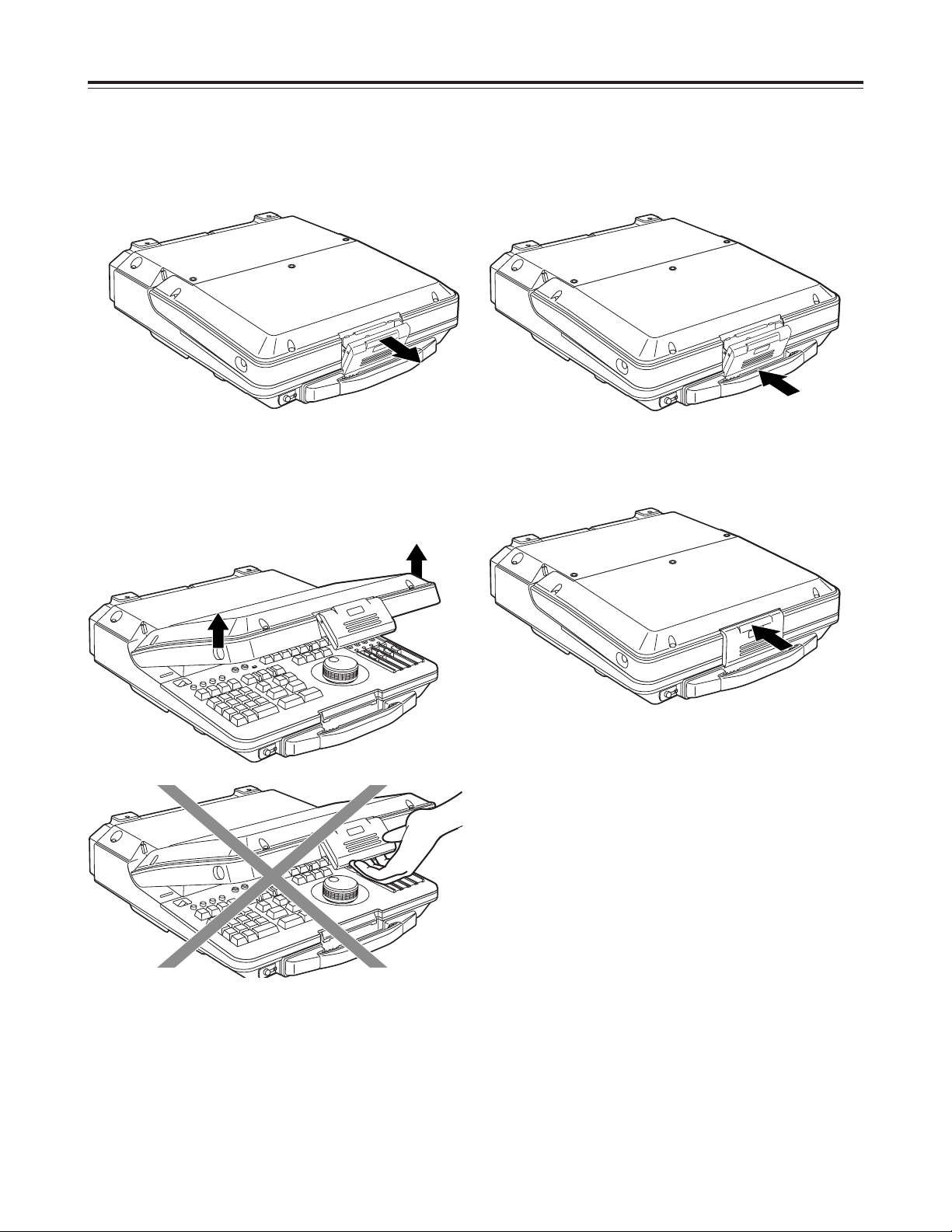
Opening the top panel
Opening and closing the top panel
Closing the top panel
1
Pull the top part of the lever forward to release the
lock.
1
Push the top panel down to close it and engage
the bottom part of the lever.
2
With the bottom part of the lever now engaged,
push up the top part of the lever to lock it.
2
Clasp both sides of the top panel, and lift the panel
to open it.
<Note>
Do not try to lift the panel by pushing the lever up.
<Note>
Take care not to pinch your fingers when opening or
closing the top panel.
7
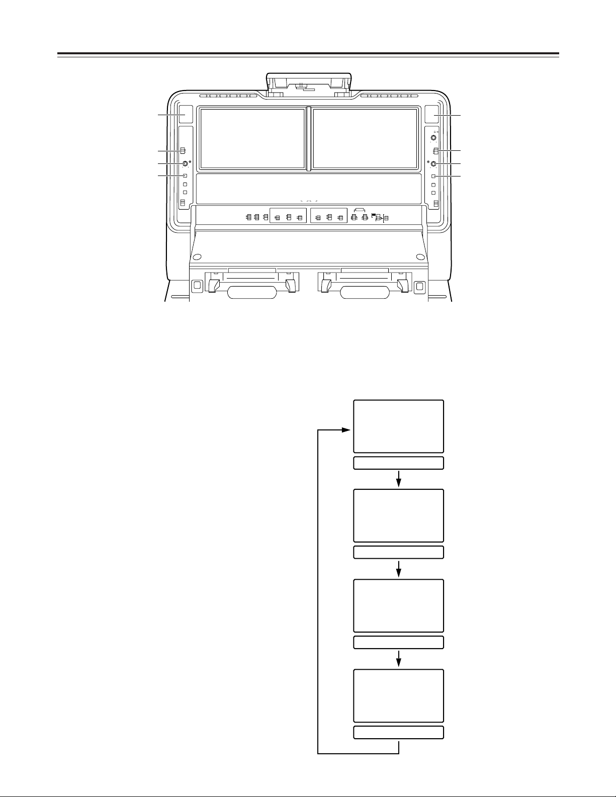
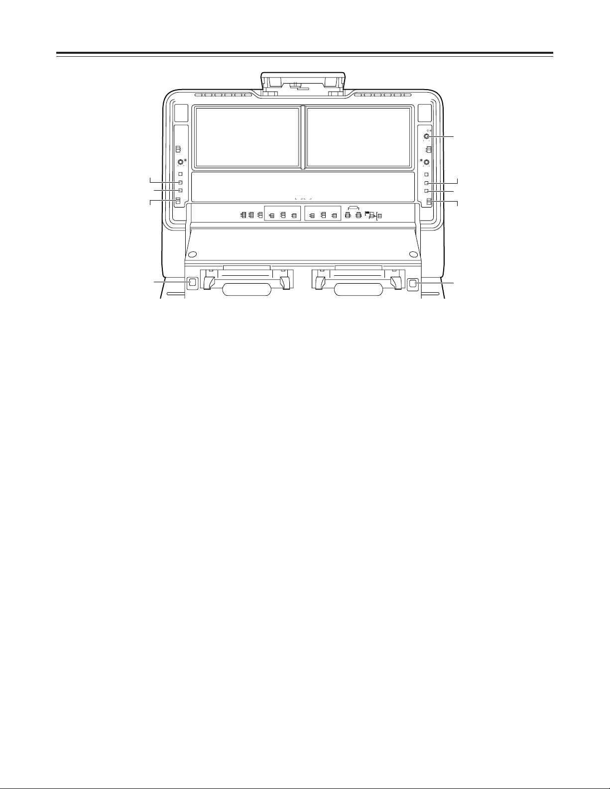
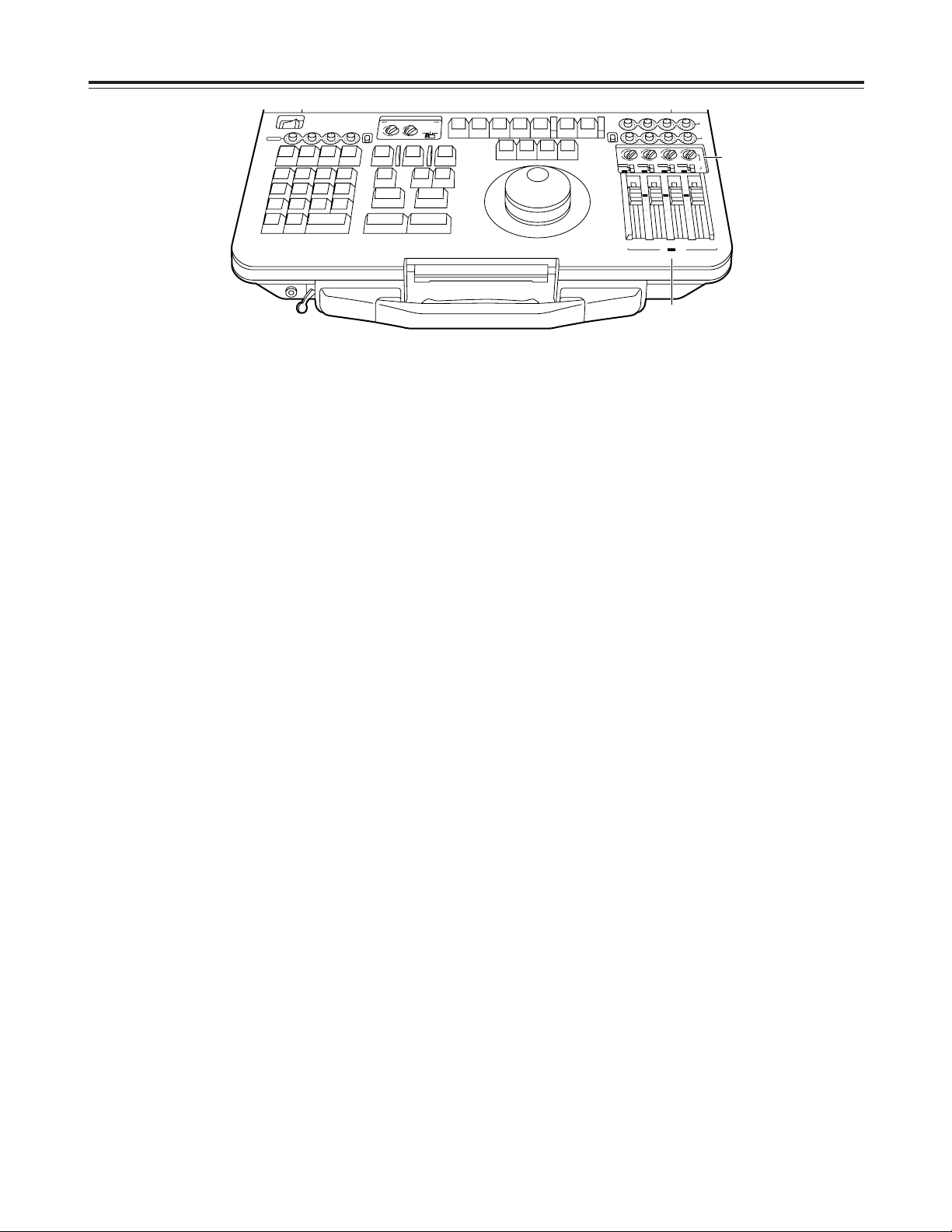
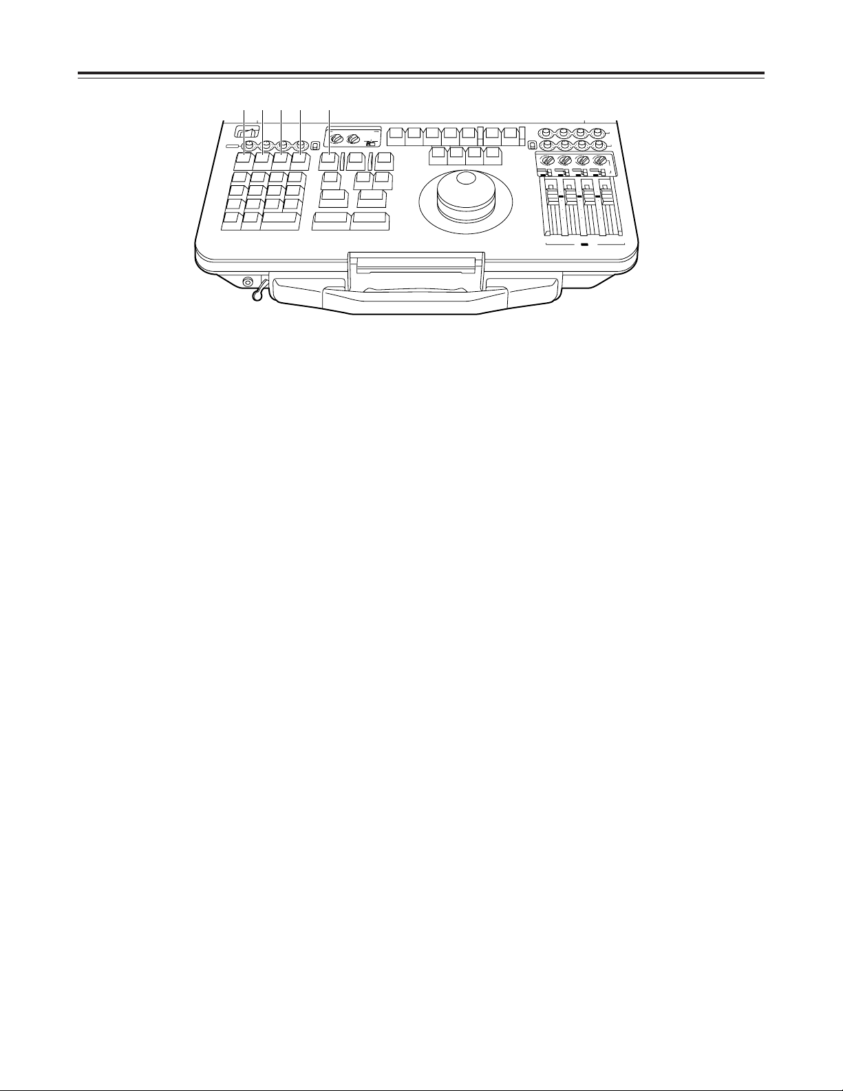
Panel control area
1
Audio monitor speakers
The sound of the VTR1 (or VTR2) signals to be
monitored is delivered through the VTR1 (or VTR2)
speaker.
Depending on the positions selected for the AUDIO
MONITOR SELECT switches, VTR1 or VTR2
sound is selected and output.
2
LCD switch
This functions as the LCD monitor power switch,
and it also selects the brightness of the display’s
backlight.
LIGHT
: For increasing the display’s backlight
brightness.
DARK
: For reducing the display’s backlight
brightness.
OFF
: The LCD monitor is turned off.
3
BRIGHTNESS control
Used to adjust the brightness of the LCD monitor.
4
COUNTER/REMAIN switch
This is used to switch what is to be shown on the
display tube and the superimposed display position
on the monitor screen.
Each time the switch is pressed, the display is
changed in the sequence presented below.
Counter/operation mode
display (top position)
Counter display
No on-screen display
Counter display
Counter/operation mode
display (bottom position)
Counter display
Counter/operation mode
display (bottom position)
DC voltage/remaining tape
display
(“11.8V/82 minutes” is
indicated in the figure.)
Parts and their functions
1
2
2
3
4
1
3
4
TCR00:00:04:14
SHTL+0.0
TCR00:00:04:14
TCR00:00:04:14
SHTL+0.0
TCR00:00:04:14
TCR00:00:04:14
SHTL+0.0
11.8v r 82
TCR00:00:04:14
BACKLIGHT
LIGHT
DARK
OFF
BRIGHTNESS
COUNTER/
REMAIN
METER
FULL/
FINE
RESET
CTL
TC
UB
CH CONDITION CH CONDITION
CONTROL
PREROLL SYNCHRO
REMOTE
7
CF
5
ON
LOCAL
OFF
3
EXT VTR
LEVEL ·
BACKLIGHT
LIGHT
DARK
OFF
BRIGHTNESS
COUNTER/
EVENT
V1 V2
VTR 1
REC INHIBIT
MODE
TC
REGEN
TAPE
ON
R-RUN
EE
OFF
F-RUN
VTR 2
TC
MODE
REGEN
TAPEEEON
R-RUN
F-RUN
REC INHIBIT
OFF
OPERATION
ANALOG
V2
MODE
VIDEO IN
EDIT
AUDIO
IN
OUT
SDI
INT
2
CH
2
CH
V1-V2
EXT
V1
4
CH
4
CH
V2
ANALOG
SEPARATE
REMAIN
METER
FULL/
FINE
RESET
CTL
TC
UB
EJECT
<
VTR 1
M-cassette
Caution Do not Insert S-cassette or with adaptor
M-cassette
Caution Do not Insert S-cassette or with adaptor
EJECT
<
VTR 2
8
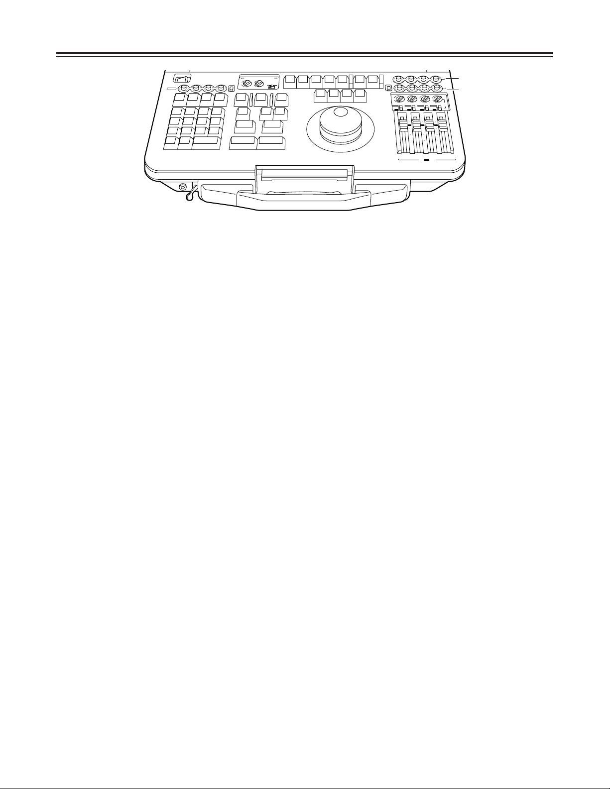
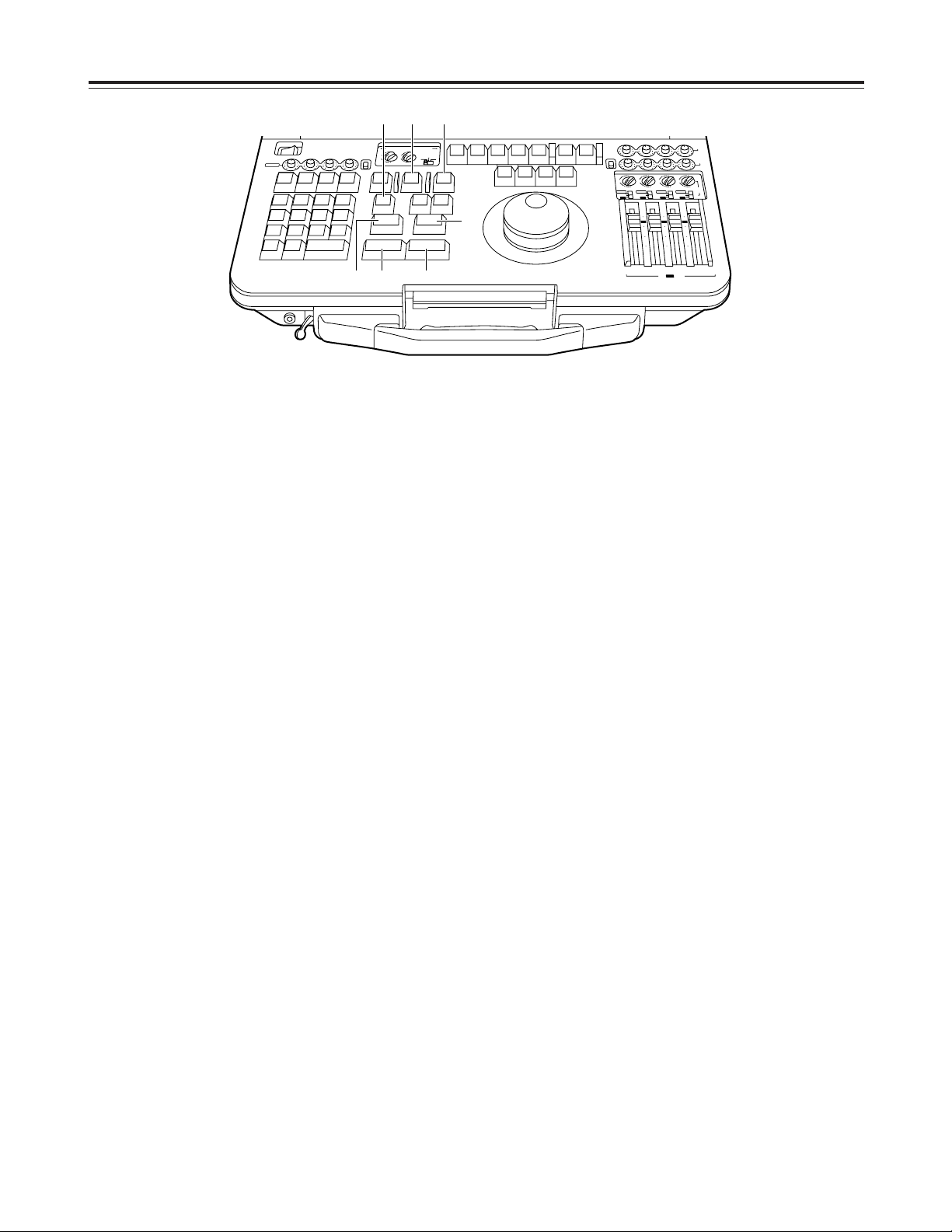
Panel control area
5
METER button
While this is held down, the audio level meter is set
to the fine mode. (See page 10)
6
RESET button
Used to reset the CTL counter.
7
COUNTER switch
CTL
: The CTL pulse count after resetting is shown
on the counter display area. It is reset by the
RESET button.
TC
: The time code which has been read out is
displayed. It is not reset even if the RESET
button is pressed.
UB
: The user’s bit of the time code which has been
read out is displayed.
8
EJECT button
Press this to eject the tape.
9
LEVEL control
Used to adjust the output level of the internal
speakers and headphones.
Parts and their functions
9
6
8
5
6
7
8
5
7
BACKLIGHT
LIGHT
DARK
OFF
BRIGHTNESS
COUNTER/
REMAIN
METER
FULL/
FINE
RESET
CTL
TC
UB
CH CONDITION CH CONDITION
CONTROL
PREROLL SYNCHRO
REMOTE
7
CF
5
ON
LOCAL
OFF
3
EXT VTR
LEVEL ·
BACKLIGHT
LIGHT
DARK
OFF
BRIGHTNESS
COUNTER/
EVENT
V1 V2
VTR 1
REC INHIBIT
MODE
TC
REGEN
TAPE
ON
R-RUN
EE
OFF
F-RUN
VTR 2
TC
MODE
REGEN
TAPEEEON
R-RUN
F-RUN
REC INHIBIT
OFF
OPERATION
ANALOG
V2
MODE
VIDEO IN
EDIT
AUDIO
IN
OUT
SDI
INT
2
CH
2
CH
V1-V2
EXT
V1
4
CH
4
CH
V2
ANALOG
SEPARATE
REMAIN
METER
FULL/
FINE
RESET
CTL
TC
UB
EJECT
<
M-cassette
Caution Do not Insert S-cassette or with adaptor
VTR 1
M-cassette
Caution Do not Insert S-cassette or with adaptor
EJECT
<
VTR 2
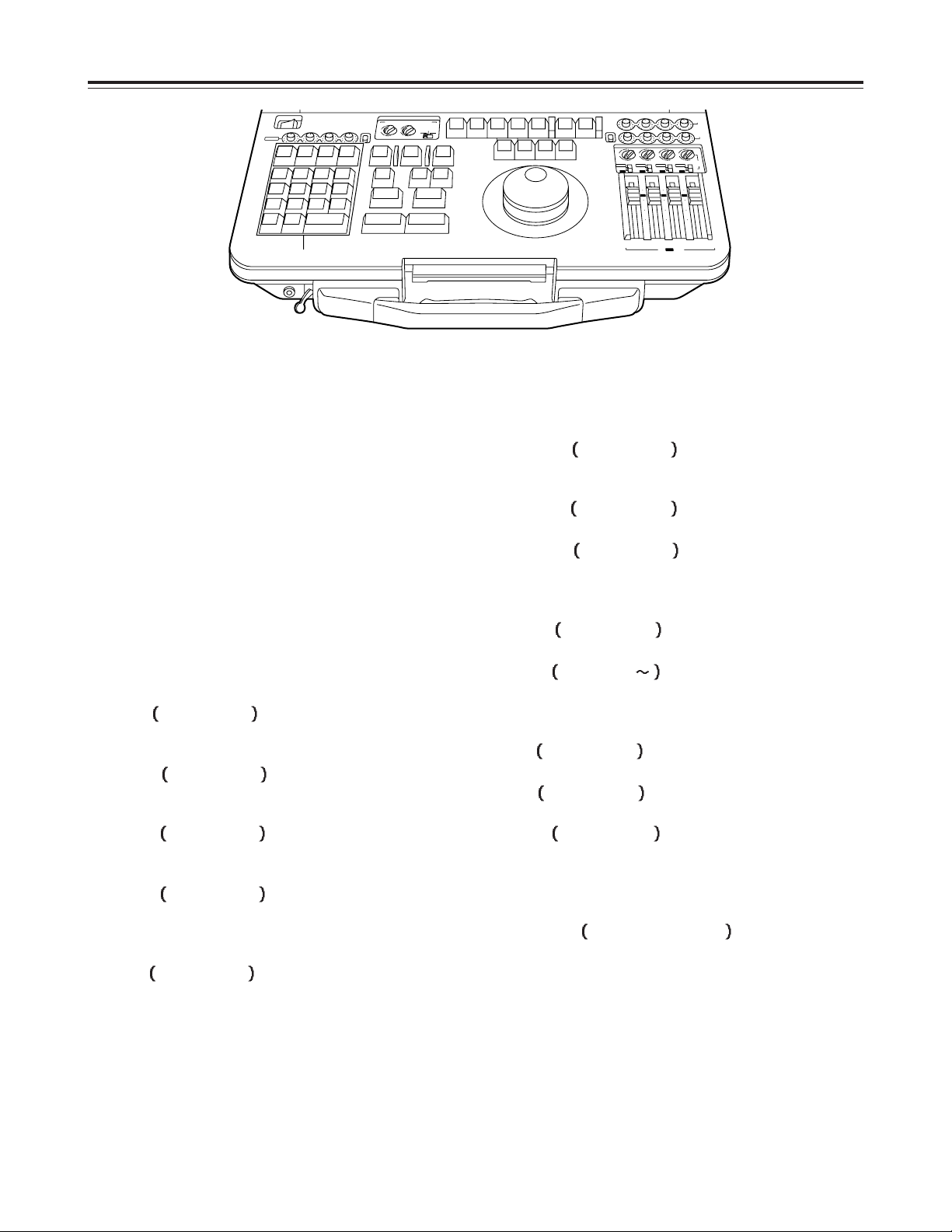
9
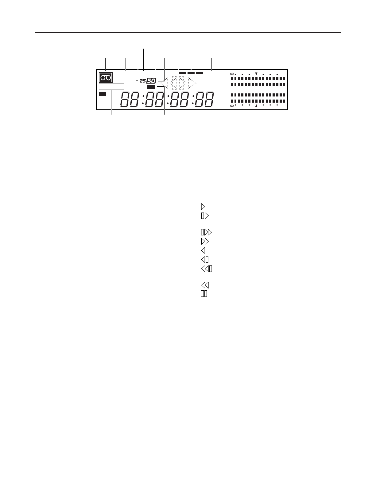
Counter display area
1
“Cassette inside” display
This lights when a cassette has been inserted.
It flashes when the unit is in the STANDBY OFF
mode.
2
INPUT SCH lamp
INPUT lights when video signals have been
supplied from an external source.
SCH also lights when the SC-H (subcarrier to
horizontal) phase matches and analog composite
signals are input.
3
REF SCH lamp
REF lights when the reference signal has been
supplied to the REF VIDEO IN connector.
SCH also lights when the SC-H phase matches and
the reference signal is input.
4
EDIT REC/REC/REC INH lamp
EDIT REC
: This lights when the unit is in the edit
recording mode.
REC
: This lights when the unit is in the
recording mode.
REC INH
: This lights when the unit is in the
recording inhibited mode.
5
CF lamp
This lights when the color frame is locked.
6
SERVO lamp
This lights when the servo is locked.
7
25/50 lamps
25
: This lights during DVCPRO (25 Mbps mode)
recording or playback.
50
: This lights during DVCPRO (50 Mbps mode)
recording or playback.
8
625 lamps
This lights when the 625i TV system has been
selected.
9
Operation modes
: For normal playback and recording.
: For playback at less than the normal speed
(1a).
: For playback at a speed faster than 1a.
: For fast forwarding.
: For reverse playback at 1a.
: For reverse playback at less than 1a.
: For reverse playback at a speed faster than
1a.
: For rewinding.
: For pause/still.
:
Channel condition lamps (green “blue “red)
Green
: This lights when the error rate of the video
playback signals or audio playback signals is
acceptable.
Blue
: This lights when the error rate of either the
video playback signals or audio playback
signals has deteriorated.
The playback picture and sound are still
normal even when this lamp is on.
Red
: This lights when the error rate of either the
video playback signals or audio playback
signals has been subject to correction or
interpolation.
;
SDI lamp
The signals of the VTR for which this lamp is lighted
are output from the SDI OUT connector.
VTR1 or VTR2 is selected by setup menu item
No.174 (SDI OUT).
Parts and their functions
CTL
TC
UB
3
CH
4
CH
CH
2
CH
1
-
30dB20 16 12 8 4 0
INPUT SCH
REF SCH
SDI
DF
SERVOCF
TOTAL
REMAIN
EDIT REC
INH
525W625
-
30dB20 16 12 8 4 0
1 2 3
5
4 8
6 7 ;9 :
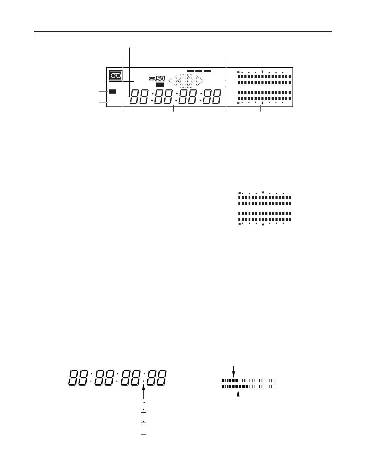
10
Counter display area
<
TOTAL lamp
This lights when the total editing time is displayed.
=
REMAIN lamp
This lights when the remaining tape amount is
displayed.
>
W lamp
This lights in the wide-screen mode.
?
DF lamp
This lights in the drop frame mode.
@
CTL lamp
This lights when the time counter serves as the
CTL counter.
A
TC lamp
This lights when the time counter shows the time
code.
B
UB lamp
This lights when the time counter shows the user’s
bit.
C
Time counter display
D
Audio level meter
Parts and their functions
CTL
TC
UB
3
CH
4
CH
CH
2
CH
1
-
30dB20 16 12 8 4 0
INPUT SCH
REF SCH
SDI
DF
SERVOCF
TOTAL
REMAIN
EDIT REC
INH
525W625
-
30dB20 16 12 8 4 0
@ <
>
?
A
B C = D
HOURS MINUTES SECONDS FRAMES
In the non-drop frame mode:
In the drop frame mode:
Time code cannot be read:
3
CH
4
CH
CH
2
CH
1
-
30dB20 16 12 8 4 0
-
30dB20 16 12 8 4 0
Pressing the METER button sets the audio level
meter to the fine mode.
Using the 4mark as the reference level (–20 dB
for 525i mode; –18 dB for 625i mode), the scale
increments are set at 1 dB intervals.
Audio signals at the reference level can be input
from an external source and their recording level
adjusted.
When a blank tape or the unrecorded part of a tape
is played, fast forwarded or rewound, the audio
level meter is set to the tape position display mode,
and the present tape travel position is indicated as
a percentage.
Display example:
The tape is now running through a position which is equivalent to
36% along the tape from its start.
Scale increments in 10’s indicating the
first digit of the percentage figure: 3
Scale increments in 1’s indicating the
second digit of the percentage figure: 6

11
Counter display area
E
Event number display lamps
This unit controls up to 200 sets of edit data (001 to
200) in the form of 3-digit event numbers. One of
the following displays appears depending on the
editing status.
n###
: Indicates that the No.### event is a new
event which has not been stored on the EDL
(edit list). (New event)
d###
: Indicates that the No.### event is an event
which has been deleted from the EDL.
###
: Indicates that the No.### event has been
stored on the EDL.
FULL
: Indicates that all 200 events have now been
stored.
----
: Indicates that the remote switch or the
OPERATION MODE switch has been set to
SEPARATE.
r S t
: Appears when the unit has been reset after
the power was turned on.
r###
: Indicates that the No.### event is an event
that has been edited.
F
Edit point setting display lamps (IN/OUT lamps)
The lamp corresponding to the type of edit point
which has been set lights.
G
Split editing display lamps (A SP, V SP lamps)
These light when split editing has been set.
Set the setup menu No. 375 (SPLIT EDIT) setting
to AUDIO and register a split edit point. The A SP
lamp lights to indicate that the audio spit edit mode
has been established.
Similarly, set it to VIDEO and register a split editing
point and the V SP lamp lights to indicate that the
video split mode has been established.
H
Split edit point setting display lamps
These are positioned at the side of the IN lamps,
and they light up for the VTR which is used to set
the split edit point.
Parts and their functions
AV
SP
IN
OUT
IN
OUT
F
E
F
H
G

12
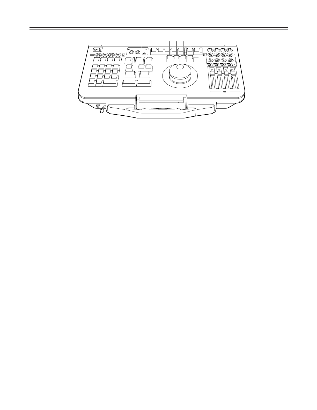
Panel switch area
1
CONTROL switch
REMOTE
: For controlling the unit from the REMOTE
connector (9P).
LOCAL
: For controlling the unit using the controls
on its front panel.
EXT VTR
: For controlling an external VTR using the
controls on the unit’s front panel. The
VTR connected to the 9P connector of
VTR1 can be controlled using the control
system of VTR1.
<Note>
This switch is forcibly set to the LOCAL position in
the 625i mode.
2
PREROLL switch
Used to set the preroll time to 3, 5 or 7 seconds.
When the phase synchronization does not serve
the purpose or editing has failed or for other
reasons, the preroll time is automatically set to the
next longest setting. (If 7 seconds is set, this will
remain set as the preroll time.)
3
SYNCHRO switch
Used to set the phase synchronization and/or color
framing.
CF
: Phase synchronization and color framing are
performed.
ON
: Phase synchronization is performed but color
framing is not performed.
OFF
: Phase synchronization is not performed.
4
TAPE/EE switch
Used to select the signals which are output in the
stop, fast forward or rewind mode.
TAPE
: The signals played back from the tape are
output.
EE
: The input-switched input signals are output.
5
TC switch
REGEN
: The built-in time code generator is
synchronized to the time code selected by
the setup menu item No.570 (REGEN SEL)
setting.
R-RUN
: The time code advances only during
recording. (Presettable)
F-RUN
: The time code advances regardless of the
operation mode while the power remains
on. (Presettable)
6
REC INHIBIT switch
Used to select whether signals are to be recorded
on the cassette tape.
ON
: Recording on the cassette tape is inhibited. At
this time, the REC INH lamp in the display
tube lights.
OFF
: Recording on the tape is possible provided
that the accidental erasure prevention
mechanism on the cassette tape is at the
recording enable position.
Parts and their functions
CONTROL
REMOTE
LOCAL
EXT VTR
PREROLL SYNCHRO
7
5
3
CF
ON
OFF
REGEN
R-RUN
F-RUN
MODE
REC INHIBIT
TC
VTR 1
TAPE
EE
ON
OFF
REGEN
R-RUN
F-RUN
MODE
REC INHIBIT
TC
VTR 2
TAPE
EE
ON
OFF
ANALOG
OPERATION
MODE
EDIT
V2
VIDEO IN
SDI
ANALOG
SEPARATE
EXT
AUDIO
IN
V1-V2
V1
V2
OUT
2
CH
4
CH
2
CH
4
CH
INT
4 5 6 4 5 6321

13
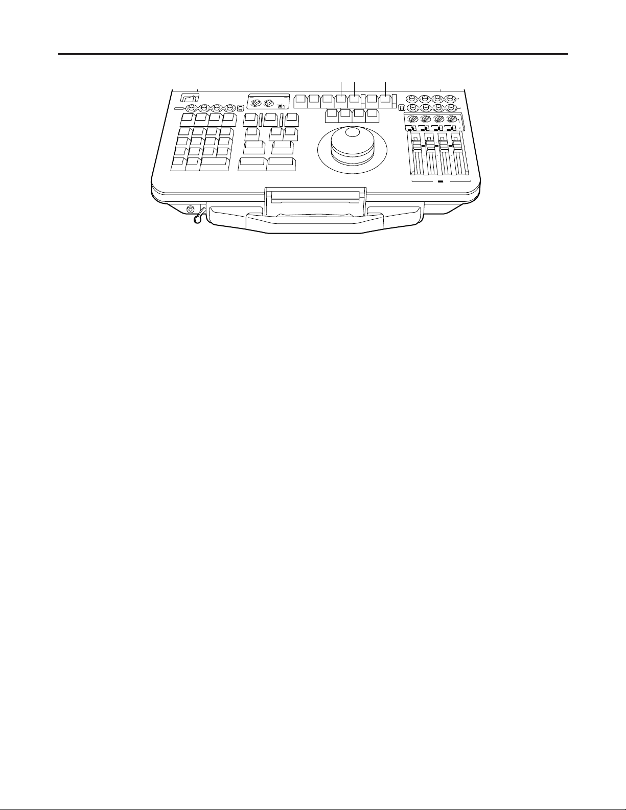
Panel switch area
7
ANALOG AUDIO IN switch
Used to set the allocation of the audio signals to the
4 analog audio input connectors (on the rear panel).
V1-V2 (2ch)
: Of the 4 inputs, the two on the VTR1
side are supplied to the VTR1’s input
connectors, and the two on the VTR2
side are supplied to the VTR2’s input
connectors.
V1 (4ch)
: The 4 inputs are allocated to the 4
channels of VTR1.
V2 (4ch)
: The 4 inputs are allocated to the 4
channels of VTR2.
8
ANALOG AUDIO OUT switch
Used to set the allocation of the audio signals to the
4 analog audio output connectors (on the rear
panel).
V1-V2 (2ch)
: Of the 4 outputs, two on the VTR1 side
are supplied to the VTR1’s output
connectors, and two on the VTR2 side
are supplied to the VTR2’s output
connectors.
V1 (4ch)
: The 4 outputs are allocated to the 4
channels of VTR1.
V2 (4ch)
: The 4 outputs are allocated to the 4
channels of VTR2.
9
OPERATION MODE switch
INT
: In this mode, editing from VTR1 to VTR2 is
accomplished using the internal connections.
VTR1 recording is prohibited.
EXT
: In this mode, editing from VTR1 to VTR2 is
accomplished using the external analog
connections.
VTR1 recording is prohibited.
SEPARATE
:
In this mode, VTR1 and VTR2 are operated
independently.
:
V2 VIDEO input selector switch
Used to select the video input of VTR2 when the
OPERATION MODE switch is at the EXT or
SEPARATE position.
SDI
: Serial digital video signals are input.
ANALOG
: Analog video signals are input.
Parts and their functions
CONTROL
REMOTE
LOCAL
EXT VTR
PREROLL SYNCHRO
7
5
3
CF
ON
OFF
REGEN
R-RUN
F-RUN
MODE
REC INHIBIT
TC
VTR 1
TAPE
EE
ON
OFF
REGEN
R-RUN
F-RUN
MODE
REC INHIBIT
TC
VTR 2
TAPE
EE
ON
OFF
ANALOG
OPERATION
MODE
EDIT
V2
VIDEO IN
SDI
ANALOG
SEPARATE
EXT
AUDIO
IN
V1-V2
V1
V2
OUT
2
CH
4
CH
2
CH
4
CH
INT
7 8 9 :
14
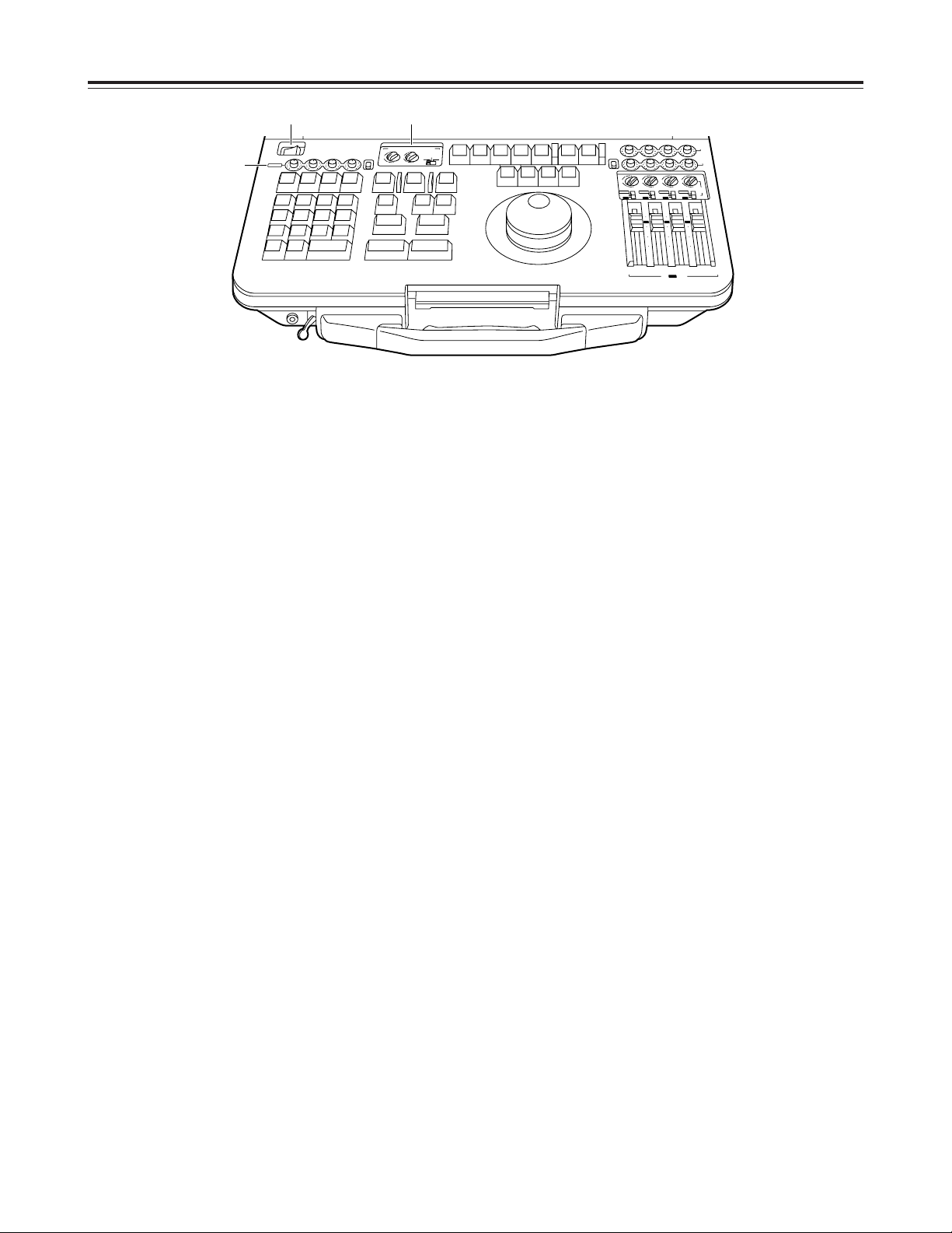
AUDIO control area
1
POWER switch
Used to control the unit’s power.
2
AUDIO MONITOR SELECT switches
Used to select the audio monitor output and
speaker output.
O
V1/V1•2/V2 switch
V1
: The VTR1 sound is output to the left and
right channels.
V1•2
: The VTR1 sound is output to the left
channel and the VTR2 sound to the right
channel.
V2
: The VTR2 sound is output to the left and
right channels.
O
L (V1) switch, R (V2) switch
The selected audio channel sound is output to
the left (or right) channel. When mixing between
1 and 2, the mixed signals of channel 1 and
channel 2 are output; when mixing between 3
and 4, the mixed signals of channel 3 and
channel 4 are output.
3
Analog audio recording level controls and
UNI/VAR switch
For each analog audio input connector (XLR) on
the rear panel there is one level control.
When the UNI/VAR switch is set to VAR, the audio
recording level can be adjusted separately for each
input channel.
When it is set to UNI, the levels are fixed to the
initial values regardless of the positions of the level
controls.
<Note>
When V2 IN is selected as the setup menu item
No.172 (VTR1 IN SEL) setting and the same sound
is to be recorded on VTR1 and VTR2, the recording
level for both VTR1 and VTR2 is adjusted using
these controls. (The recording level cannot be
adjusted separately for VTR1 and VTR2.)
Parts and their functions
1 2
3
POWER
OFF
CH 1
V1/V2
ANALOG
REC
N
T
E
V
E
E
T
E
L
D
E
78
U
T
E
S
P
456
T
IS
L
C
O
R
1
2
D
U
M
P
O
A
D
L
0C
P
D
IS
IT
X
E
ON
CH 2 CH 3 CH 4
IN
O
U
X
T
A
S
L
E
T
A
S
L
9
G
D
IA
C
T
R
A
C
K
T
3
S
T
E
T
E
N
T
E
U
R
N
T
R
E
T
D
F
-
B
S
+
S
F
R
AUDIO MONITOR SELECT
MIX
MIX
4
3
3
UNI
2
2
MIX
MIX
1
LR
VAR
D
U
R
O
G
O
T
G
O
T
O
U
T
O
T
A
L
O
T
S
P
L
IT
~
/T
C
M
A
R
K
IN
S
IF
T
H
CH 1
M
A
S
B
L
VA
1
A
2
CR
T
C
E
D
IT
4
(V1·2)
V1 V2
D
IT
E
T
S
1
A
3
A
1
U
A
T
O
V
E
IE
W
R
P
E
D
IT
I
T
M
U
L
IE
V
R
E
W
V
1
T
R
V
T
R
2
M
A
K
R
U
O
T
L
L
A
S
T
P
O
CH 3 4
P
L
S
4
Y
A
S
T
I
L
L
O
P
T
F
F
B
O
T
S
E
R
E
W
F
F
UNI
VAR
MIX
3
2
MIX
ANALOG
SDI
INT
CH 2 CH 3 CH 4
MIX
4
3
2
MIX
1
ANALOG
SDI
INT
10
0
10
20
30
00
CH 1 CH 2
V2
PB
SDI
REC
MIX
MIX
4
4
4
3
3
2
2
MIX
MIX
1
1
1
V2
INPUT
ANALOG
ANALOG
SDI
SDI
INT
INT
10
10
0
0
10
10
20
20
30
30
00
00
CH 3 CH 4
INT
V2
REC
/ V1 PB
15
AUDIO control area
4
V1 audio playback level controls/V2 INT audio
recording level controls
These controls enable the playback audio level of
VTR1 to be adjusted for each channel.
They are also used to adjust the volume during
editing from VTR1 to VTR2.
Slide controls are used to make for fine and smooth
adjustments.
The position marked “0” denotes the reference
level.
(–20 dB for 525i mode; –18 dB for 625i mode)
5
V2 AUDIO input selector switches
Used to select the sound which is to be input to the
audio channels of VTR2.
O
INT/SDI/ANALOG switch
INT
: The VTR1 audio signals are input to VTR2
by the internal digital connections. Their
level can be adjusted by the level controls
4
.
SDI
: The SDI embedded audio signals, which
have been input to the SDI connector, are
supplied to VTR2. Their level can be
adjusted by the level controls 6.
ANALOG
:
The analog signals which have been input
are supplied to VTR2. Their level can be
adjusted by the level controls 3.
O
Channel selector switches
The audio signals selected by the
INT/SDI/ANALOG switch are input to the VTR2
channels which are selected by these switches.
When mixing between 1 and 2, the mixed signals
of channel 1 and channel 2 are input; when
mixing between 3 and 4, the mixed signals of
channel 3 and channel 4 are input.
Parts and their functions
AUDIO MONITOR SELECT
LR
CH 1
4
1
3
MIX
ANALOG
MIX
2
UNI
V2
PB
SDI
REC
VAR
CH 2 CH 3 CH 4
CH 3 4
4
(V1·2)
V1 V2
1
3
MIX
MIX
2
4
1
3
MIX
MIX
A
S
M
B
L
V
A
1
A
2
1
S
T
E
D
IT
P
R
E
V
IE
W
V
T
R
2
V
T
R
1
S
P
L
I
T
M
A
R
K
O
U
T
M
A
R
K
IN
S
H
I
F
T
E
N
T
E
R
A
L
L
S
T
O
P
R
E
V
IE
W
A
U
T
O
E
D
IT
M
U
L
T
I
G
O
T
O
G
O
T
O
O
U
T
D
U
R
T
O
T
A
L
O
U
T
L
A
S
T
E
D
IN
L
A
S
T
X
E
V
E
N
T
7
89
456
1
2
0C
3
~
-
+
D
E
L
E
T
E
S
E
T
U
P
F
/T
C
D
IA
G
L
IS
T
C
O
R
C
T
B
S
T
R
A
C
K
D
U
M
P
L
O
A
D
F
S
D
IS
P
E
X
IT
R
E
T
U
R
N
T
S
E
T
P
L
A
Y
S
T
O
P
S
T
IL
L
R
E
W
F
F
S
T
B
O
F
F
A
3A
4
T
CR
E
C
E
D
IT
2
4
1
3
MIX
MIX
2
4
1
3
MIX
MIX
2
4
1
3
MIX
MIX
2
SDI
CH 1 CH 2
V2
/ V1 PB
REC
CH 3 CH 4
INT
ANALOG
SDI
10
10
20
30
00
INT
INT
ANALOG
SDI
INT
ANALOG
SDI
V2
INPUT
INT
0
10
10
20
30
00
0
10
10
20
30
00
0
CH 1
POWER
OFF
ON
UNI
VAR
CH 2 CH 3 CH 4
ANALOG
V1/V2
REC
4
5
16
AUDIO control area
6
SDI audio recording level controls and UNI/VAR
switch
For each channel of the superimposed sound which
is input from the SDI input connector (on the rear
panel) there is one level control.
When the UNI/VAR switch is set to VAR, the audio
recording level can be adjusted separately for each
input channel.
When it is set to UNI, the levels are fixed to the
initial value regardless of the positions of the level
controls.
7
V2 audio playback level controls
These controls enable the playback audio level of
VTR2 to be adjusted for each channel.
Parts and their functions
AUDIO MONITOR SELECT
LR
CH 1
4
1
3
MIX
ANALOG
MIX
2
UNI
V2
PB
SDI
REC
VAR
CH 2 CH 3 CH 4
CH 3 4
4
(V1·2)
V1 V2
1
3
MIX
MIX
2
4
1
3
MIX
MIX
A
S
M
B
L
VA
1
A
2
1
S
T
E
D
IT
P
R
E
V
IE
W
V
T
R
2
V
T
R
1
S
P
L
IT
M
A
R
K
O
U
T
M
A
R
K
IN
S
H
IF
T
E
N
T
E
R
A
L
L
S
T
O
P
R
E
V
IE
W
A
U
T
O
E
D
I
T
M
U
L
T
I
G
O
T
O
G
O
T
O
O
U
T
D
U
R
T
O
T
A
L
O
U
T
L
A
S
T
E
D
IN
L
A
S
T
X
E
V
E
N
T
789
456
1
2
0C
3
~
-
+
D
E
L
E
T
E
S
E
T
U
P
F
/T
C
D
IA
G
L
IS
T
C
O
R
C
T
B
S
T
R
A
C
K
D
U
M
P
L
O
A
D
F
S
D
IS
P
E
X
IT
R
E
T
U
R
N
T
S
E
T
P
L
A
Y
S
T
O
P
S
T
IL
L
R
E
W
F
F
S
T
B
O
F
F
A
3
A
4
T
CR
E
C
E
D
IT
2
4
1
3
MIX
MIX
2
4
1
3
MIX
MIX
2
4
1
3
MIX
MIX
2
SDI
CH 1 CH 2
V2
/ V1 PB
REC
CH 3 CH 4
INT
ANALOG
SDI
10
10
20
30
00
INT
INT
ANALOG
SDI
INT
ANALOG
SDI
V2
INPUT
INT
0
10
10
20
30
00
0
10
10
20
30
00
0
CH 1
POWER
OFF
ON
UNI
VAR
CH 2 CH 3 CH 4
ANALOG
V1/V2
REC
7
6
17
Editing operation area
1
VTR1 selector button
Press this button to perform VTR1 editing-related
settings or operations.
Check that its LED has lighted before proceeding
with the VTR1 editing-related settings or
operations.
2
VTR2 selector button
Press this button to perform VTR2 editing-related
settings or operations.
Check that its LED has lighted before proceeding
with the VTR2 editing-related settings or
operations.
<Note>
The VTR1 and VTR2 simultaneous operation mode
is established by pressing ([SHIFT] + [VTR1]) or
([SHIFT] + [VTR2]) together, and both LEDs 1and
2
light.
To release the simultaneous operation mode, press
the VTR1 or VTR2 button.
In the simultaneous operation mode, it is not
possible for editing settings and menu settings to
be performed at the same time.
3
REC button
To set the unit to the recording mode manually,
press this button together with the PLAY button.
Recording on VTR1 is possible only when the
OPERATION MODE switch has been set to
SEPARATE.
When the button is pressed while the REC INHIBIT
switch is at OFF, the E-E mode will be established
for the video/audio channel 1 to channel 4 signals
for as long as the button is held down.
4
PLAY (STOP) button
PLAY
: Press this button to set the VTR to the
playback mode.
STOP ([SHIFT] + [PLAY])
:
To set the VTR to the STOP mode, press the
PLAY button while holding down the SHIFT
button.
5
STILL (STBY OFF) button
STILL
: Press this button to set the unit to the still-
picture mode.
STBY OFF ([SHIFT] + [STILL])
:
To release the standby mode while the stillpicture or stop mode is established, press the
STILL button while holding down the SHIFT
button.
6
REW button
Press this button to rewind the tape.
7
FF button
Press this button to fast forward the tape.
<Note>
Tape travel stops when the REW and FF buttons
are pressed at the same time.
Parts and their functions
AUDIO MONITOR SELECT
LR
CH 1
4
1
3
MIX
ANALOG
MIX
2
UNI
V2
PB
SDI
REC
VAR
CH 2 CH 3 CH 4
CH 3 4
4
(V1·2)
V1 V2
1
3
MIX
MIX
2
4
1
3
MIX
MIX
A
S
M
B
L
VA
1
A
2
1
S
T
E
D
IT
P
R
E
V
IE
W
V
T
R
2
V
T
R
1
S
P
L
IT
M
A
R
K
O
U
T
M
A
R
K
I
N
S
H
IF
T
E
N
T
E
R
A
L
L
S
T
O
P
R
E
V
IE
W
A
U
T
O
E
D
IT
M
U
L
T
I
G
O
T
O
G
O
T
O
O
U
T
D
U
R
T
O
T
A
L
O
U
T
L
A
S
T
E
D
IN
L
A
S
T
X
E
V
E
N
T
789
456
1
2
0C
3
~
-
+
D
E
L
E
T
E
S
E
T
U
P
F
/T
C
D
IA
G
L
IS
T
C
O
R
C
T
B
S
T
R
A
C
K
D
U
M
P
L
O
A
D
F
S
D
IS
P
E
X
IT
R
E
T
U
R
N
T
S
E
T
P
L
A
Y
S
T
O
P
S
T
IL
L
R
E
W
F
F
S
T
B
O
F
F
A
3A
4
T
CR
E
C
E
D
IT
2
4
1
3
MIX
MIX
2
4
1
3
MIX
MIX
2
4
1
3
MIX
MIX
2
SDI
CH 1 CH 2
V2
/ V1 PB
REC
CH 3 CH 4
INT
ANALOG
SDI
10
10
20
30
00
INT
INT
ANALOG
SDI
INT
ANALOG
SDI
V2
INPUT
INT
0
10
10
20
30
00
0
10
10
20
30
00
0
CH 1
POWER
OFF
ON
UNI
VAR
CH 2 CH 3 CH 4
ANALOG
V1/V2
REC
1 4 5 6 32
7

18
Editing operation area
8
Search dial
This is used to control the tape travel. It is also
used when edit points are to be located or when
playing back tapes.
The shuttle mode is established when the dial is
“out” (up), and the jog mode is established when it
is pushed in.
Each time the dial is pressed, the unit alternates
between these two modes.
9
ASMBL (1ST EDIT) button
ASMBL
:
Press this button to initiate assemble editing.
Check that its LED has lighted before proceeding
with editing.
1ST EDIT ([SHIFT] + [ASMBL])
:
The editing tape must have black burst signals,
time codes or CTL signals recorded on it ahead
of time. To initiate first editing, press the ASMBL
button while holding down the SHIFT button.
For further details, refer to page 53 (“Preparing
tapes for editing”).
:
V button
Press this button to initiate video insert editing.
Check that its LED has lighted before proceeding
with editing.
;
A1 (A3) button
A1
: Press this button to initiate audio channel 1
insert editing.
Check that its LED has lighted before
proceeding with editing.
A3 ([SHIFT] + [A1])
:
To initiate audio channel 3 insert editing, press
the A1 button while holding down the SHIFT
button.
Check that its LED has lighted before
proceeding with editing.
<Note>
The A3 LED will light in the 25 Mbps mode also but
CH3 editing operations cannot be performed.
Parts and their functions
AUDIO MONITOR SELECT
LR
CH 1
4
1
3
MIX
ANALOG
MIX
2
UNI
V2
PB
SDI
REC
VAR
CH 2 CH 3 CH 4
CH 3 4
4
(V1·2)
V1 V2
1
3
MIX
MIX
2
4
1
3
MIX
MIX
A
S
M
B
L
VA
1
A
2
1
S
T
E
D
IT
P
R
E
V
IE
W
V
T
R
2
V
T
R
1
S
P
L
IT
M
A
R
K
O
U
T
M
A
R
K
IN
S
H
IF
T
E
N
T
E
R
A
L
L
S
T
O
P
R
E
V
IE
W
A
U
T
O
E
D
IT
M
U
L
T
I
G
O
T
O
G
O
T
O
O
U
T
D
U
R
T
O
T
A
L
O
U
T
L
A
S
T
E
D
IN
L
A
S
T
X
E
V
E
N
T
78
9
456
1
2
0C
3
~
-
+
D
E
L
E
T
E
S
E
T
U
P
F
/T
C
D
IA
G
L
IS
T
C
O
R
C
T
B
S
T
R
A
C
K
D
U
M
P
L
O
A
D
F
S
D
IS
P
E
X
IT
R
E
T
U
R
N
T
S
E
T
P
L
A
Y
S
T
O
P
S
T
I
L
L
R
E
W
F
F
S
T
B
O
F
F
A
3
A
4
T
CR
E
C
E
D
IT
2
4
1
3
MIX
MIX
2
4
1
3
MIX
MIX
2
4
1
3
MIX
MIX
2
SDI
CH 1 CH 2
V2
/ V1 PB
REC
CH 3 CH 4
INT
ANALOG
SDI
10
10
20
30
00
INT
INT
ANALOG
SDI
INT
ANALOG
SDI
V2
INPUT
INT
0
10
10
20
30
00
0
10
10
20
30
00
0
CH 1
POWER
OFF
ON
UNI
VAR
CH 2 CH 3 CH 4
ANALOG
V1/V2
REC
9 : ;
8
19
Editing operation area
<
A2 (A4) button
A2
: Press this button to initiate audio channel 2
insert editing.
Check that its LED has lighted before
proceeding with editing.
A4 ([SHIFT] + [A2])
:
To initiate audio channel 4 insert editing, press
the A2 button while holding down the SHIFT
button.
Check that its LED has lighted before
proceeding with editing.
<Note>
The A4 LED will light in the 25 Mbps mode also but
CH4 editing operations cannot be performed.
=
TC button
Press this button to initiate time code insert editing.
Check that its LED has lighted before proceeding
with editing.
>
EDIT button
When this button is pressed during VTR2 playback,
the E-E mode is established in accordance with the
selected edit mode (ASMBL, A1, A2, A3, A4 or TC)
for as along as the button is held down. (Select EE)
When it is pressed together with the PLAY button
during VTR2 playback, editing is initiated in the
selected edit mode (ASMBL, A1, A2, A3, A4 or TC).
(Manual editing)
To exit manual editing, press the ALL STOP button.
Parts and their functions
AUDIO MONITOR SELECT
LR
CH 1
4
1
3
MIX
ANALOG
MIX
2
UNI
V2
PB
SDI
REC
VAR
CH 2 CH 3 CH 4
CH 3 4
4
(V1·2)
V1 V2
1
3
MIX
MIX
2
4
1
3
MIX
MIX
A
S
M
B
L
VA
1
A
2
1
S
T
E
D
IT
P
R
E
V
IE
W
V
T
R
2
V
T
R
1
S
P
L
IT
M
A
R
K
O
U
T
M
A
R
K
IN
S
H
IF
T
E
N
T
E
R
A
L
L
S
T
O
P
R
E
V
IE
W
A
U
T
O
E
D
I
T
M
U
L
T
I
G
O
T
O
G
O
T
O
O
U
T
D
U
R
T
O
T
A
L
O
U
T
L
A
S
T
E
D
IN
L
A
S
T
X
E
V
E
N
T
789
45
6
12
0C
3
~
-
+
D
E
L
E
T
E
S
E
T
U
P
F
/T
C
D
IA
G
L
IS
T
C
O
R
C
T
B
S
T
R
A
C
K
D
U
M
P
L
O
A
D
F
S
D
IS
P
E
X
IT
R
E
T
U
R
N
T
S
E
T
P
L
A
Y
S
T
O
P
S
T
IL
L
R
E
W
F
F
S
T
B
O
F
F
A
3A4
T
CR
E
C
E
D
IT
2
4
1
3
MIX
MIX
2
4
1
3
MIX
MIX
2
4
1
3
MIX
MIX
2
SDI
CH 1 CH 2
V2
/ V1 PB
REC
CH 3 CH 4
INT
ANALOG
SDI
10
10
20
30
00
INT
INT
ANALOG
SDI
INT
ANALOG
SDI
V2
INPUT
INT
0
10
10
20
30
00
0
10
10
20
30
00
0
CH 1
POWER
OFF
ON
UNI
VAR
CH 2 CH 3 CH 4
ANALOG
V1/V2
REC
< = >
20
Editing operation area
?
EVENT button
EVENT
:
To change the event number, press this button,
then use the numeric input keys to input the
event number, and press the ENTER button.
DELETE ([SHIFT] + [EVENT])
:
Press this button to delete an event which has
been registered.
“d” is indicated in the event number display area.
@
IN (LAST X) button
IN
: Press this button to set or display an edit IN
point.
LAST X ([SHIFT] + [IN])
:
To re-register an event which has been deleted,
press this button while holding down the SHIFT
button.
The “d” indication is cleared to a blank display.
A
OUT (LAST ED) button
OUT
:
Press this button to set or display an edit OUT
point.
LAST ED ([SHIFT] + [OUT])
:
To return to the previously previewed data, press
this button while holding down the SHIFT button.
B
DUR (TOTAL) button
DUR
:
Press this button to set or display the duration.
TOTAL ([SHIFT] + [DUR])
:
To show the total editing time on the VTR2
display, press this button while holding down the
SHIFT button.
C
GO TO (GO TO OUT) button
GO TO
:
To search the edit IN point on the tape with the
edit IN point already set, press this button.
GO TO OUT ([SHIFT] + [GO TO])
:
To search the edit OUT point on the tape with
the edit OUT point already set, press this button
while holding down the SHIFT button.
Parts and their functions
AUDIO MONITOR SELECT
LR
CH 1
4
1
3
MIX
ANALOG
MIX
2
UNI
V2
PB
SDI
REC
VAR
CH 2 CH 3 CH 4
CH 3 4
4
(V1·2)
V1 V2
1
3
MIX
MIX
2
4
1
3
MIX
MIX
A
S
M
B
L
VA
1
A
2
1
S
T
E
D
IT
P
R
E
V
IE
W
V
T
R
2
V
T
R
1
S
P
L
I
T
M
A
R
K
O
U
T
M
A
R
K
IN
S
H
IF
T
E
N
T
E
R
A
L
L
S
T
O
P
R
E
V
IE
W
A
U
T
O
E
D
IT
M
U
L
T
I
G
O
T
O
G
O
T
O
O
U
T
D
U
R
T
O
T
A
L
O
U
T
L
A
S
T
E
D
IN
L
A
S
T
X
E
V
E
N
T
789
45
6
1
2
0C
3
~
-
+
D
E
L
E
T
E
S
E
T
U
P
F
/T
C
D
IA
G
L
IS
T
C
O
R
C
T
B
S
T
R
A
C
K
D
U
M
P
L
O
A
D
F
S
D
IS
P
E
X
IT
R
E
T
U
R
N
T
S
E
T
P
L
A
Y
S
T
O
P
S
T
IL
L
R
E
W
F
F
S
T
B
O
F
F
A
3
A
4
T
CR
E
C
E
D
IT
2
4
1
3
MIX
MIX
2
4
1
3
MIX
MIX
2
4
1
3
MIX
MIX
2
SDI
CH 1 CH 2
V2
/ V1 PB
REC
CH 3 CH 4
INT
ANALOG
SDI
10
10
20
30
00
INT
INT
ANALOG
SDI
INT
ANALOG
SDI
V2
INPUT
INT
0
10
10
20
30
00
0
10
10
20
30
00
0
CH 1
POWER
OFF
ON
UNI
VAR
CH 2 CH 3 CH 4
ANALOG
V1/V2
REC
? @ A B C
21
Editing operation area
D
AUTO EDIT/END (MULTI EDIT) button
AUTO EDIT/END
:
Press this button to initiate automatic editing.
When editing was initiated without setting the
OUT point (open-ended editing), press this
button to end the editing and store the point at
which the button was pressed as the OUT point.
MULTI EDIT ([SHIFT] + [AUTO EDIT])
:
Press this button while holding down the SHIFT
button to initiate multi-event editing. Multi-event
editing is now executed automatically until the
last event is edited or until the operation is
forcibly ended by pressing the ALL STOP button.
E
PREVIEW (REVIEW) button
PREVIEW
:
Press this button to rehearse the editing.
REVIEW ([SHIFT] + [PREVIEW])
:
Press this button while holding down the SHIFT
button to check the results of the editing.
F
SPLIT button
Press this button to initiate split editing.
Check that its LED has lighted, and set the split IN
point.
G
MARK IN button
Press this button to set an edit IN point by reading
the VTR’s time code or CTL.
Press it while holding down the SHIFT button to set
the split IN point.
H
MARK OUT button
Press this button to set an edit OUT point by
reading the VTR’s time code or CTL.
I
SHIFT button
To use any of the functions indicated at the bottom
of the buttons, press the button concerned while
holding down the SHIFT button.
J
ALL STOP button
Press this button to shut down all the VTR’s
operations.
During editing (PREVIEW, EDIT REVIEW), the
editing operation concerned is suspended.
Parts and their functions
AUDIO MONITOR SELECT
LR
CH 1
4
1
3
MIX
ANALOG
MIX
2
UNI
V2
PB
SDI
REC
VAR
CH 2 CH 3 CH 4
CH 3 4
4
(V1·2)
V1 V2
1
3
MIX
MIX
2
4
1
3
MIX
MIX
A
S
M
B
L
VA
1
A
2
1
S
T
E
D
IT
P
R
E
V
IE
W
V
T
R
2
V
T
R
1
S
P
L
IT
M
A
R
K
O
U
T
M
A
R
K
IN
S
H
IF
T
E
N
T
E
R
A
L
L
S
T
O
P
R
E
V
IE
W
A
U
T
O
E
D
I
T
M
U
L
T
I
G
O
T
O
G
O
T
O
O
U
T
D
U
R
T
O
T
A
L
O
U
T
L
A
S
T
E
D
IN
L
A
S
T
X
E
V
E
N
T
789
45
6
12
0C
3
~
-
+
D
E
L
E
T
E
S
E
T
U
P
F
/T
C
D
IA
G
L
IS
T
C
O
R
C
T
B
S
T
R
A
C
K
D
U
M
P
L
O
A
D
F
S
D
IS
P
E
X
IT
R
E
T
U
R
N
T
S
E
T
P
L
A
Y
S
T
O
P
S
T
IL
L
R
E
W
F
F
S
T
B
O
F
F
A
3A4
T
CR
E
C
E
D
IT
2
4
1
3
MIX
MIX
2
4
1
3
MIX
MIX
2
4
1
3
MIX
MIX
2
SDI
CH 1 CH 2
V2
/ V1 PB
REC
CH 3 CH 4
INT
ANALOG
SDI
10
10
20
30
00
INT
INT
ANALOG
SDI
INT
ANALOG
SDI
V2
INPUT
INT
0
10
10
20
30
00
0
10
10
20
30
00
0
CH 1
POWER
OFF
ON
UNI
VAR
CH 2 CH 3 CH 4
ANALOG
V1/V2
REC
F D E
G I J
H
22
Editing operation area
K
Numeric input buttons
0, 1, 2, 3, 4, 5, 6, 7, 8, 9:
Used to set the edit data, etc. by inputting the
numeric values of the data.
C:
Used to clear the numeric values or other edit
data entered.
+/–:
Used to change the edit data or change the
settings in the setup mode, etc.
ENTER:
Used to enter the edit data, etc. as numeric
values.
DISP
[SHIFT] + [0] :
Used to set the superimposing on the LCD
monitor screen ON or OFF.
DUMP
[SHIFT] + [1]
:
Press to transfer edit data (EDL) to an external
component.
LOAD
[SHIFT] + [2] :
Press to load edit data (EDL) from an external
component into the internal EDL memory.
T SET
[SHIFT] + [3] :
Used to set the time code generator’s initial
values when the TC generator switch is at the
preset (R-RUN or F-RUN) position.
LIST
[SHIFT] + [4] :
Used to display the edit data on the monitor
screen.
CORCT
[SHIFT] + [5] :
Press to change the edit data which has already
been stored in the EDL memory.
TRACK
[SHIFT] + [6] :
Press to initiate time track processing.
SET UP
[SHIFT] + [7] :
Press to perform the settings for the whole
system.
The setup menus appear on the monitor screen.
DIAG
[SHIFT] + [9] :
Used to display the DIAG MENU, etc.
F/TC
[SHIFT] + [ ] :
Used to select whether the numeric values will
be input in time codes or in frames when these
values are to be input.
FS
[SHIFT] + [+] :
Press to change to the next event.
BS
[SHIFT] + [–] :
Press to change to the previous event.
EXIT
[SHIFT] + [C] :
Press to stop the input of the edit points or other
data at any time.
In the setup mode, this discards the settings and
exits the setup mode.
RETURN
[SHIFT] + [ENTER] :
Press to stop the input of the edit points or other
data at any time.
In the setup mode, this enters the settings.
Parts and their functions
K
POWER
OFF
ON
CH 1
V1/V2
ANALOG
REC
N
T
E
V
E
IN
E
T
E
L
D
E
X
T
A
S
L
7
89
U
T
E
S
P
456
T
IS
L
C
O
R
C
T
1
2
D
U
M
P
O
A
D
L
0
C
P
D
IS
IT
X
E
CH 2 CH 3 CH 4
O
U
T
E
T
A
S
D
L
G
D
IA
F
-
R
A
C
K
T
B
S
3
+
S
T
E
T
S
F
E
N
T
E
R
U
R
N
T
R
E
AUDIO MONITOR SELECT
MIX
MIX
4
3
3
UNI
2
2
MIX
MIX
1
LR
VAR
D
U
R
O
G
O
T
G
O
T
O
O
U
T
T
A
L
O
T
S
P
L
IT
~
/T
C
R
M
A
K
IN
S
IF
T
H
CH 1
M
A
S
B
L
VA
1
A
2
CR
T
C
E
D
IT
4
(V1·2)
V1 V2
D
IT
E
T
S
1
1
A
T
O
U
V
E
IE
W
R
P
E
D
IT
I
T
M
U
L
IE
V
R
E
W
V
T
R
1
V
T
R
2
M
A
K
R
T
U
O
L
L
A
S
T
P
O
A
3
CH 3 4
P
S
A
4
Y
L
A
S
T
IL
L
T
O
P
F
F
B
O
T
S
E
E
R
W
F
F
UNI
VAR
MIX
3
2
MIX
ANALOG
SDI
INT
CH 2 CH 3 CH 4
MIX
4
3
2
MIX
1
ANALOG
SDI
INT
10
0
10
20
30
00
CH 1 CH 2
V2
PB
SDI
REC
MIX
MIX
4
4
4
3
3
2
2
MIX
MIX
1
1
1
V2
INPUT
ANALOG
ANALOG
SDI
SDI
INT
INT
10
10
0
0
10
10
20
20
30
30
00
00
CH 3 CH 4
INT
V2
REC
/ V1 PB
23
Encoder control area
(VTR1)
Encoder and systems adjustments can be performed using these controls for the video signals to be output to an
external device.
<Note>
The VTR2 controls are positioned symmetrically to the VTR1 controls.
VTR1 controls (side panel)
1
VIDEO LEVEL control
Used to adjust the video level of the video output
signals.
2
SET UP control
Used to adjust the setup level of the video output
signals.
3
HUE control
Used to adjust the hue of the video output signals.
4
CHROMA LEVEL control
Used to adjust the chroma level of the video output
signals.
5
SYSTEM controls
Used to perform the system adjustments when a
reference video signal is to be input for
synchronization purposes.
H
: Used to adjust the system’s horizontal phase (in
subcarrier cycle increments).
SC FINE
:
Used to adjust the system’s subcarrier phase.
(It is capable of 90-degree P-P continuous
adjustments.)
SC COARSE
:
Used to adjust the system’s subcarrier phase.
(It has 4 positions, each of which corresponds to
90 degrees.)
<Note>
It may not be possible to adjust the phase in the 625i
mode even when the system adjustments at the VTR1
side are performed.
Parts and their functions
12345
COARSE
SC
FINE
SYSTEM
VIDEO
H
LEVEL
SET UPHUECHROMA
LEVEL
24
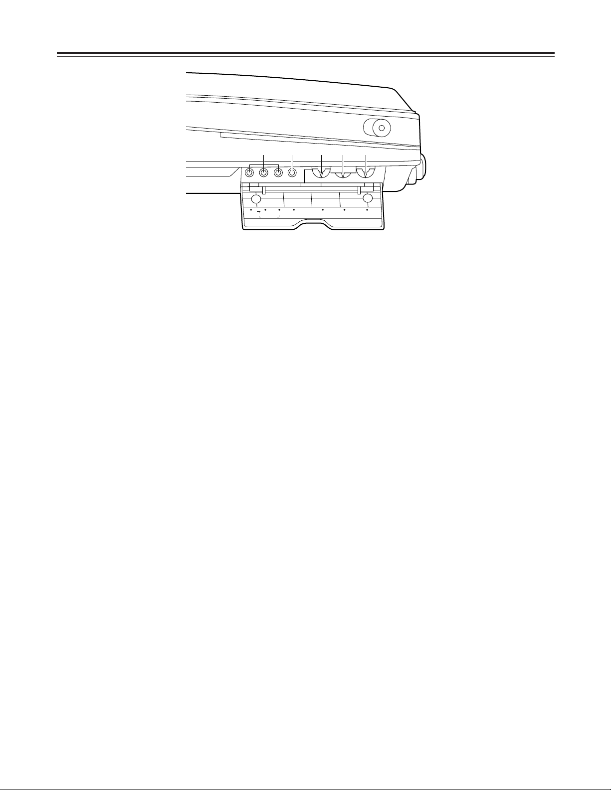
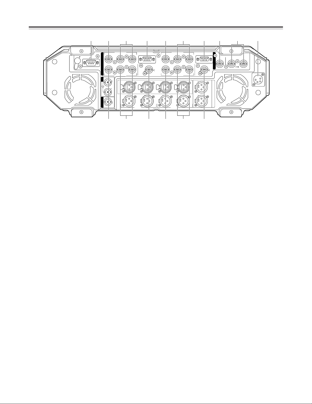
Connector area
1
EDL connector (D-SUB 9P)
Connect a personal computer or other external unit
to this connector to upload and download the edit
data.
2
TC IN connector (BNC)
The external time code signal (LTC) is supplied to
this connector.
3
REF VIDEO IN connectors (BNC a2, loopthrough)
These are automatically terminated with a 75 Ω
resistance.
Supply standard analog composite signals to these
connectors. The unit’s video output will be
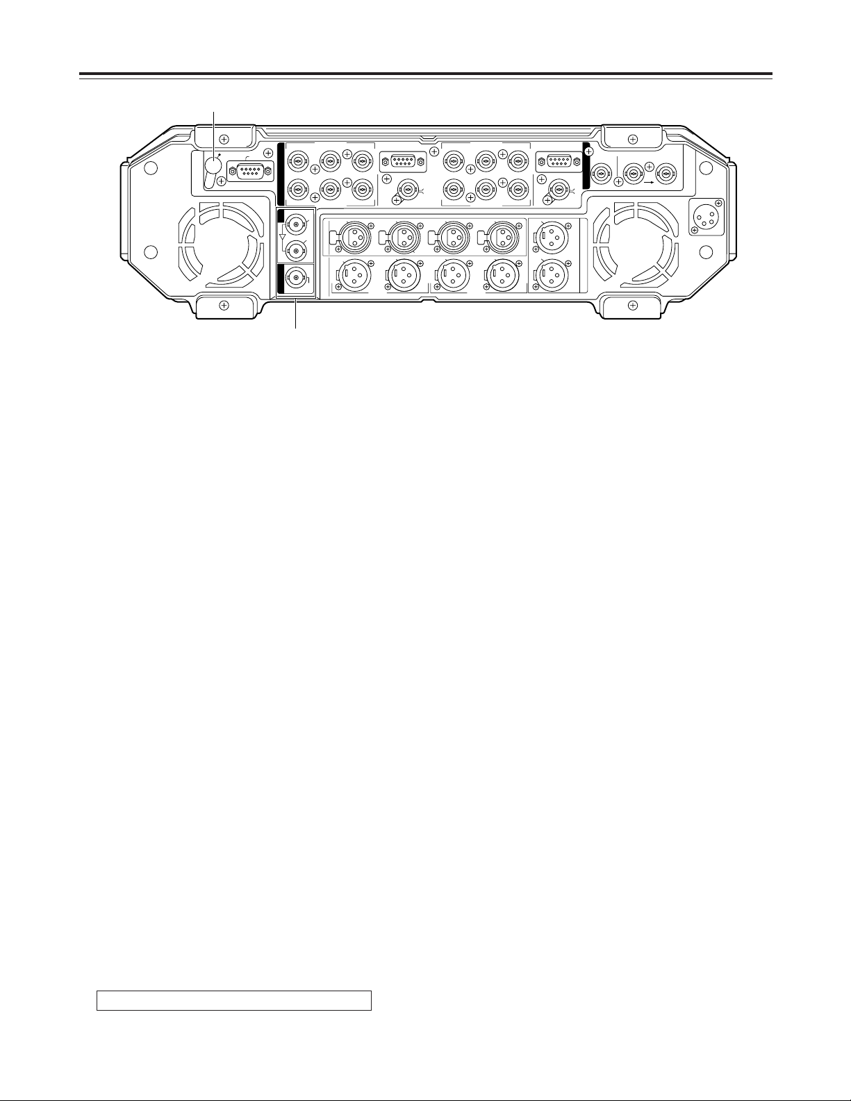
synchronized with the input signals.
4
DC IN connector (XLR 4P)
This is the DC power input socket.
The AJ-B95, available as an optional accessory
must be used for the power supply.
No guarantees are made when the unit is operated
by any other power supply.
5
VIDEO/Y IN connector (BNC)
The analog composite signals or analog component
Y (luminance) signals are supplied to this
connector.
The signals are selected using setup menu item
No.670 (V IN SEL).
6
P
B/PR
IN connectors (BNC)
The analog component P
B
and PRsignals are
supplied to these connectors.
7
REMOTE connector (D-SUB 9P)
(525i mode only)
This remote connector complies with the RS-422A
standard. It enables the unit to be controlled using
an external controller.
The remote connector of VTR1 is switched to the
REMOTE OUT connector by setting the CONTROL
switch to “EXT VTR”.
An externally connected VTR can then be
controlled using the unit’s VTR1 operation system.
8
VIDEO/Y OUT connector (BNC)
The analog composite signals or analog component
Y (luminance) signals are output from this
connector.
The signals are selected using setup menu item
No.671 (V OUT SEL).
9
P
B/PR
OUT connectors (BNC)
These are the output connectors for the analog
component P
B
and PRsignals.
:
VIDEO MONITOR OUT/TC OUT connector (BNC)
The video monitor signals are output from this
connector.
The time code signal (LTC) is output when
“TCOUT1” or “TCOUT2” has been selected as the
setup menu item No.572 (V-MON/TC OUT) setting.
Parts and their functions
DC IN
REF INTC IN
REMOTEREMOTE
V
T
R
1
A
U
D
I
O
M
O
N
O
U
T
A
U
D
I
O
I
N
A
U
D
I
O
O
U
T
VIDEO
MON
OUT
TC
OUT
75Ω AUTO
VIDEO
MON
OUT
TC
OUT
L
CH 4
VIDEO OUT
VIDEO IN
P
B
P
B
P
R
P
R
VIDEO OUT
ACTIVE THROUGH
SDI
IN
SDI
IOUT
VIDEO IN
VIDEO/Y
VIDEO/Y
EDL
NOT USER
SERVICEABLE
VIDEO/Y
VIDEO/Y
P
B
P
B
P
R
P
R
(CH 2•4)
CH 3
(CH 1•3)
CH 4
(CH 2/4)
CH 3
(CH 1/3)
CH 2
(CH 2/4)
(V2) (V1)
CH 1
(CH 1/3)
CH 2
MIC
CH 1
R
V
T
R
2
V
2
V
1
/
V
2
1 5 7 5 7 2 4366
8 : 8 :99
25
Connector area
;
SDI input/output connectors (BNC)
O
SDI input connector
This is the input connector for the component
serial digital signals.
SDI signals can be supplied to VTR2 and
recorded by setting the V2 VIDEO input selector
switch (see page 13) and V2 AUDIO input
selector switch (see page 15).
<Note>
These signals cannot be supplied to VTR1.
O
SDI ACTIVE THRU output connector
The signals supplied to the SDI input connector
are output straight through the unit via the output
buffer.
O
SDI output connector
This is the output connector for the component
serial digital signals.
The signals of the VTR selected by setup menu
item No.174 (SDI OUT) are output. “SDI” lights
on the fluorescent display tube of the selected
VTR. (See page 9)
<Note>
Do not connect either of the SDI output connectors
to the SDI input connector.
If this caution is ignored, the unit will not operate
properly even if VTR1 has been selected as the
setup menu item No.174 (SDI OUT) setting.
<
Service/maintenance switch hole
Inside this hole is a switch that is used for service
and maintenance purposes.
It should never be touched by the user.
Parts and their functions
DC IN
REF INTC IN
REMOTEREMOTE
V
T
R
1
A
U
D
I
O
M
O
N
O
U
T
A
U
D
I
O
I
N
A
U
D
I
O
O
U
T
VIDEO
MON
OUT
TC
OUT
75Ω AUTO
VIDEO
MON
OUT
TC
OUT
L
CH 4
VIDEO OUT
VIDEO IN
P
B
P
B
P
R
P
R
VIDEO OUT
ACTIVE THROUGH
SDI
IN
SDI
IOUT
VIDEO IN
VIDEO/Y
VIDEO/Y
EDL
NOT USER
SERVICEABLE
VIDEO/Y
VIDEO/Y
P
B
P
B
P
R
P
R
(CH 2•4)
CH 3
(CH 1•3)
CH 4
(CH 2/4)
CH 3
(CH 1/3)
CH 2
(CH 2/4)
(V2) (V1)
CH 1
(CH 1/3)
CH 2
MIC
CH 1
R
V
T
R
2
V
2
V
1
/
V
2
<
;
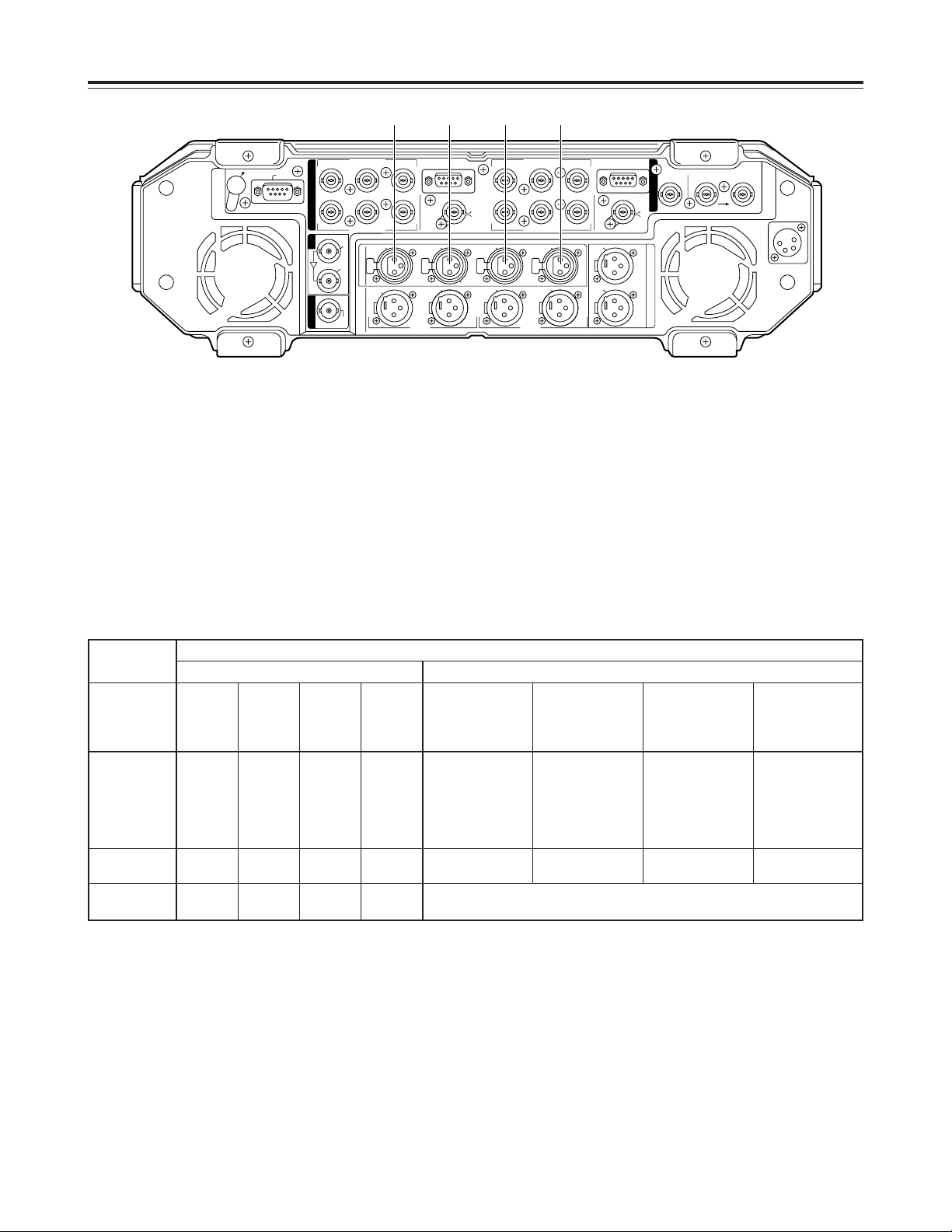
26
Connector area
=>?@
Audio input connectors (XLR)
The analog audio signals are supplied to these
connectors.
Their channel allocation can be changed as shown
below by setting the ANALOG AUDIO IN switch.
<Notes>
¢¢
1: No sound can be recorded on channels 3 and 4 in the 25 Mbps mode.
¢¢
2: The input for channels 1 and 2 (channels #1 and #2 from the left) can be selected from “connector =input,”
“connector >input” and “connectors
=>
mixed” by setting the V2 AUDIO input selector switch (channel
selector switch). (See page 15)
¢¢
3: In the 2-channel mode, the same signals will be recorded at VTR1 on channels 1 and 3 as on channels 2
and 4.
Recording channels on tape
VTR1 VTR2
ANALOG
AUDIO IN
switch setting
Signals
input to
channel 1
Signals
input to
channel 2
Signals
input to
channel 3
(¢1)
Signals
input to
channel 4
(¢1)
Signals input to
channel 1
Signals input to
channel 2
Signals input to
channel 3
(¢1)
Signals input to
channel 4
(¢1)
V1. V2 (2ch)
Connector?Connector@Connector
?
(¢3)
Connector
@
(¢3)
Selected from:
O
Connector
=
O
Connector
>
O
Connectors
=>
mixed
(¢2)
Selected from:
O
Connector
=
O
Connector
>
O
Connectors
=>
mixed
(¢2)
Selected from:
O
Connector
=
O
Connector
>
O
Connectors
=>
mixed
(¢2)
Selected from:
O
Connector
=
O
Connector
>
O
Connectors
=>
mixed
(¢2)
Parts and their functions
V1 (4ch)
Connector=Connector>Connector?Connector
@
Sound muted Sound muted Sound muted Sound muted
V2 (4ch)
Sound
muted
Sound
muted
Sound
muted
Sound
muted
Setting the V2 AUDIO input selector switch (channel selector switch) enables
any audio signals to be selected. (See page 15)
DC IN
REF INTC IN
REMOTEREMOTE
V
T
R
1
A
U
D
I
O
M
O
N
O
U
T
A
U
D
I
O
I
N
A
U
D
I
O
O
U
T
VIDEO
MON
OUT
TC
OUT
75Ω AUTO
VIDEO
MON
OUT
TC
OUT
L
CH 4
VIDEO OUT
VIDEO IN
P
B
P
B
P
R
P
R
VIDEO OUT
ACTIVE THROUGH
SDI
IN
SDI
IOUT
VIDEO IN
VIDEO/Y
VIDEO/Y
EDL
NOT USER
SERVICEABLE
VIDEO/Y
VIDEO/Y
P
B
P
B
P
R
P
R
(CH 2•4)
CH 3
(CH 1•3)
CH 4
(CH 2/4)
CH 3
(CH 1/3)
CH 2
(CH 2/4)
(V2) (V1)
CH 1
(CH 1/3)
CH 2
MIC
CH 1
R
V
T
R
2
V
2
V
1
/
V
2
= > ? @

27
Connector area
ABCD
Audio output connectors (XLR)
The analog audio signals are output from these
connectors.
Their channel allocation can be changed as shown
below by setting the ANALOG AUDIO OUT switch.
<Notes>
¢¢
1: The output channels are selected by the setup menu item No.773 (PB AUDIO SEL) setting.
¢¢
2: Channel 3 and 4 signals are not output in the 25 Mbps mode.
ANALOG AUDIO OUT
switch setting
Output signals
from connector
A
Output signals
from connector
B
Output signals
from connector
C
Output signals
from connector
D
V1. V2 (2ch)
VTR1 channel 1
or
VTR2 channel 3
(¢1)
VTR2 channel 2
or
VTR2 channel 4
(¢1)
VTR1 channel 1
or
VTR1 channel 3
(¢1)
VTR1 channel 2
or
VTR1 channel 4
(¢1)
Parts and their functions
V1 (4ch) VTR1 channel 1 VTR1 channel 2
VTR1 channel 3
(¢2)
VTR1 channel 4
(¢2)
V2 (4ch) VTR2 channel 1 VTR2 channel 2
VTR2 channel 3
(¢2)
VTR2 channel 4
(¢2)
DC IN
REF INTC IN
REMOTEREMOTE
V
T
R
1
A
U
D
I
O
M
O
N
O
U
T
A
U
D
I
O
I
N
A
U
D
I
O
O
U
T
VIDEO
MON
OUT
TC
OUT
75Ω AUTO
VIDEO
MON
OUT
TC
OUT
L
CH 4
VIDEO OUT
VIDEO IN
P
B
P
B
P
R
P
R
VIDEO OUT
ACTIVE THROUGH
SDI
IN
SDI
IOUT
VIDEO IN
VIDEO/Y
VIDEO/Y
EDL
NOT USER
SERVICEABLE
VIDEO/Y
VIDEO/Y
P
B
P
B
P
R
P
R
(CH 2•4)
CH 3
(CH 1•3)
CH 4
(CH 2/4)
CH 3
(CH 1/3)
CH 2
(CH 2/4)
(V2) (V1)
CH 1
(CH 1/3)
CH 2
MIC
CH 1
R
V
T
R
2
V
2
V
1
/
V
2
A B C D F
E

28
Connector area
EF
AUDIO MONITOR OUT connectors (XLR)
These are the audio monitor output connectors.
Their output signals can be changed by setting the
AUDIO MONITOR SELECT switches.
$
Concerning the audio output selected for the
audio monitor connectors, internal speakers
and headphones jack (front panel)
Which channels of which VTR, either VTR1 or
VTR2, are to be selected for the audio signals
which are to be output to the audio monitor
connectors, internal speakers and headphones jack
can be changed by setting the AUDIO MONITOR
SELECT switches on the keyboard to support many
audio monitoring options.
<Notes>
O
The same signals from the same channels of the
same VTR are output to audio monitor connector
L, the internal speaker on the left side and
headphones L.
Similarly, the same signals from the same
channels of the same VTR are output to audio
monitor connector R, the internal speaker on the
right side and headphones R.
Different signals cannot be set for the connector,
speaker and headphones.
O
When the headphones are plugged into the
headphones jack on the front panel, the sound
from the internal speakers is automatically cut
off.
O
The level control (by the side of the liquid crystal
monitor) on the front panel is used to adjust the
sound through the internal speakers and
headphones.
This control cannot be used to adjust the level of
audio signals which are output to the audio
monitor connectors.
Setting method
Setting is possible when “V1+V2” has been
selected as the setup menu item No.772 (AUTO
MONI) setting.
1. To output the VTR1 sound to the L connector
and the VTR2 sound to the R connector
O
Set the V1/V1•2/V2 switch to “V1•2”.
O
Use the L (V1) switch to select the VTR1 audio
channel whose sound is to be output to the L
connector.
O
Use the R (V2) switch to select the VTR2 audio
channel whose sound is to be output to the R
connector.
<Note>
Audio mixing is possible for channels 1 and 2 or for
channels 3 or 4. No other combination of channels
can be mixed.
2. To output the VTR1 sound to both the L and R
connectors
O
Set the V1/V1•2/V2 switch to “V1”.
O
Use the L (V1) switch to select the VTR1 audio
channel whose sound is to be output to the L
connector.
O
Use the R (V2) switch to select the VTR1 audio
channel whose sound is to be output to the R
connector.
<Note>
In this mode, stereo sound consisting of VTR1
channels 1 and 2 can be produced by selecting “1”
using the L (V1) switch and “2” using the R (V2)
switch.
3. To output the VTR2 sound to both the L and R
connectors
O
Set the V1/V1•2/V2 switch to “V2”.
O
Use the L (V1) switch to select the VTR2 audio
channel whose sound is to be output to the L
connector.
O
Use the R (V2) switch to select the VTR2 audio
channel whose sound is to be output to the R
connector.
<Note>
In this mode, stereo sound consisting of VTR2
channels 1 and 2 can be produced by selecting “1”
using the L (V1) switch and “2” using the R (V2)
switch.
AUDIO MONITOR SELECT
LR
4
(V1·2)
V1 V2
1
3
MIX
MIX
2
4
1
3
MIX
MIX
2
Parts and their functions
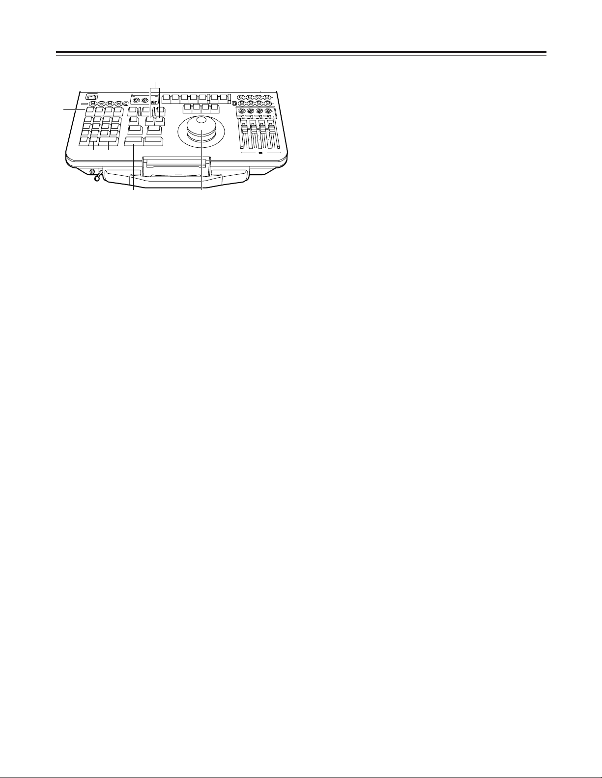
29
Setup menu operations
All the setup items except the ones which are set by
the selector switches are set on the on-screen menus.
1
Press the SET UP ([SHIFT] + [7]) button to transfer
operation to the setup menu mode.
The menu screen is displayed on the liquid crystal
monitor and video monitor output.
<Note>
Even if ON has been selected as the setup menu
item No.30 (MENU LOCK) setting, the menu
screen appears and the settings can be checked
but they cannot be changed.
4
While holding down the SHIFT button, turn the dial
and change the value. The value can be
decremented by pressing the “–” button while
holding down the SHIFT button and, conversely,
incremented by pressing the “+” button while
holding down the SHIFT button.
<Note>
To change the settings of setup menu item No.377
(1ST EDIT TC), No.378 (1ST EDIT UB), No.573
(TC PRESET) or No.574 (UB PRESET), press the
T SET ([SHIFT] + [3]) button, and use the numeric
input buttons to input the value.
The TC PRESET and UB PRESET values are set
when the TC generator switch is set to “F-RUN” or
“R-RUN”.
Follow the steps below to input characters for
setup menu item No.379 (1ST-E TITLE).
1
Press the STILL button to display the character
input screen.
2
Press the SHIFT button.
The cursor now flashes at the position where the
characters can be input.
3
While holding the SHIFT button down, select a
character by pressing the “+” or “–” button.
4
While holding the SHIFT button down, move the
character input position by pressing the “FF” or
“REW” button.
5
Repeat steps 3and
4
to input more
characters.
6
Upon completion of the character input, release
the SHIFT button, and press the STILL button to
exit the character input screen.
5
When the RETURN ([SHIFT] + [ENTER]) button is
pressed, the setting is entered, and the normal
mode is restored.
6
When the EXIT ([SHIFT] + [C]) button is pressed,
the setting is canceled, and the normal mode is
restored.
2
To perform settings on the menu displayed on the
VTR1 side, press the VTR1 button and check that
this button’s LED is lighted and that the VTR2
button’s LED is off.
To perform settings on the menu displayed on the
VTR2 side, press the VTR2 button and check that
this button’s LED is lighted and that the VTR1
button’s LED is off.
3
Push in the search dial to set the jog mode.
Turn the dial and select the item to be set. (The
“¢” cursor now moves.)
<Note>
Press the FF or REW button to scroll the menu
items to the next or previous page.
1
2
56
SHIFT DIAL
CH 1
POWER
OFF
CH 1
V1/V2
ANALOG
REC
T
N
E
V
E
E
T
E
L
E
D
789
U
T
E
P
S
456
T
IS
L
1
M
U
D
P
0C
P
IS
D
E
S
A
L
T
C
O
R
C
2
D
O
A
L
IT
X
ON
CH 2 CH 3 CH 4
IN
X
T
A
L
IA
D
C
A
R
T
3
T
E
S
T
E
N
T
E
R
AUDIO MONITOR SELECT
MIX
3
UNI
2
MIX
LR
VAR
T
O
U
R
U
D
G
O
T
O
G
O
T
T
U
O
O
E
T
D
S
L
A
O
T
T
S
P
L
IT
~
G
/T
C
F
-
R
A
M
IN
K
S
B
+
S
F
S
H
T
IF
E
T
R
N
R
U
M
L
B
S
A
VA
1
2
A
C
T
C
E
MIX
4
4
3
(V1·2)
V1 V2
2
IT
D
E
T
S
1
MIX
1
1
U
O
T
A
IT
E
D
I
T
M
L
U
1
V
T
R
K
A
M
R
U
O
A
S
L
L
T
A
CH 3 4
V
W
IE
E
R
P
IE
V
E
W
R
V
T
R
2
K
T
P
O
3A
4
P
L
A
Y
S
O
P
T
S
T
S
R
L
T
IL
E
W
R
F
F
F
F
O
B
CH 2 CH 3 CH 4
V2
MIX
4
3
2
MIX
1
ANALOG
CH 1 CH 2
PB
SDI
REC
MIX
MIX
4
4
4
3
3
2
2
MIX
MIX
1
1
1
V2
INPUT
ANALOG
ANALOG
SDI
SDI
SDI
INT
INT
INT
10
10
10
0
0
0
10
10
10
20
20
20
30
30
30
00
00
00
CH 3 CH 4
INT
V2
REC
/ V1 PB
IT
D
E
UNI
VAR
MIX
3
2
MIX
ANALOG
SDI
INT

30
Setup menu operations
This unit has a user memory function in which users
can store settings.
If a particular set of settings is stored, they can be
recalled altogether.
It is also possible to recall the factory settings in one
go.
(The TC PRESET and UB PRESET values can
neither be stored nor recalled.)
Storing settings in the user memory
Recalling settings registered in the user
memory
User memory and factory settings
1
Press the SET UP ([SHIFT] + [7]) button to set the
unit to the setup mode.
2
Make the changes to the desired settings.
3
Press the RESET button of VTR2 to display the
initial setting screen.
1
Press the SET UP ([SHIFT] + [7]) button to set the
unit to the setup mode.
2
Press the RESET button of VTR2 to display the
initial setting screen.
3
Press the LOAD ([SHIFT] + [2]) button to recall the
settings from the user memory.
Recalling the factory settings
(menu reset)
1
Press the SET UP ([SHIFT] + [7]) button to set the
unit to the setup mode.
2
Press the RESET button of VTR2 to display the
initial setting screen.
3
O
If the PLAY button is pressed, all the items are
returned to their factory settings.
O
If the STILL button is pressed, all the items
except for the system items are returned to their
factory settings.
O
If the REW button is pressed, recalling the
factory settings is canceled.
4
Press the DUMP ([SHIFT] + [1]) button to store the
changed settings in the user memory.
SETUP-MENU INIT SET
VTR1&2 OK?
ALL<PLAY>/
NOT SYSTEM<STILL>/
NO<REW>/
USER LOAD <LOAD>/
USER SAVE <DUMP>
 Loading...