

Panasonic aj-lt85 Operation Manual
Operating Instructions
Lap Top Editor
P
DIGITAL VIDEO
CASSETTE
AJ-
Printed in Japan
VQT7628
P
B
S0698H1068-100
FOR YOUR SAFETY
CAUTION
RISK OF ELECTRIC SHOCK
DO NOT OPEN
CAUTION: TO REDUCE THE RISK OF ELECTRIC SHOCK,
DO NOT REMOVE COVER (OR BACK).
NO USER-SERVICEABLE PARTS INSIDE.
REFER SERVICING TO QUALIFIED SERVICE PERSONNEL.
The lightning flash with arrowhead symbol, within an
equilateral triangle, is intended to alert the user to the
presence of uninsulated “dangerous voltage” within
the product’s enclosure that may be of sufficient
magnitude to constitute a risk of electric shock to
persons.
The exclamation point within an equilateral triangle is
intended to alert the user to the presence of important
operating and maintenance (servicing) instructions in
the literature accompanying the appliance.
CAUTION:
To reduce the risk of fire or shock hazard
and annoying interference, use the
recommended accessories only.
WARNING:
To reduce the risk of fire or shock hazard,
do not expose this equipment to rain or
moisture.
is the safety information.
IMPORTANT
“Unauthorized recording of copyrighted television programs, video tapes and other materials
may infringe the right of copyright owners and
be contrary to copyright laws.”
Do not insert fingers or any objects into the video
casette holder.
Avoid operating or leaving the unit near strong
magnetic fields. Be especially careful of large audio
speakers.
Avoid operating or storing the unit in an excessively
hot, cold, or damp environment as this may result in
damage both to the unit and to the tape.
Do not spray any cleaner or wax directly on the unit.
If the unit is not going to be used for a length of time,
protect it from dirt and dust.
Do not leave a cassette in the unit when not in use.
Do not block the ventilation slots of the unit.
■
■
■
■
■
■
■
Use this unit horizontally and do not place anything on
the top panel.
Cassette tape can be used only for one-side, one
direction recording. Two-way or two-track recordings
cannot be made.
Cassette tape can be used for either Color or Black &
White recording.
Do not attempt to disassemble the unit.
There are no user serviceable parts inside.
If any liquid spills inside the unit, have the unit
examined for possible damage.
Refer any needed servicing to authorized service
personnel.
■
■
■
■
■
■
FCC Note:
This device complies with Part 15 of the FCC Rules.
To assure continued compliance follow the attached
installation instructions and do not make any
unauthorized modifications.
This equipment has been tested and found to comply
with the limits for a Class A digital device, pursuant to
Part 15 of the FCC Rules. These limits are designed
to provide reasonable protection against harmful
interference when the equipment is operated in a
commercial environment. This equipment generates,
uses, and can radiate radio frequency energy and, if
not installed and used in accordance with the instruction manual, may cause harmful interference to radio
communications. Operation of this equipment in a
residential area is likely to cause harmful interference
in which case the user will be required to correct the
interference at his own expense.
2

CONTENTS
Introduction ………………………………………………………… 4
Features ………………………………………………………… 4
Controls and their functions ………………………………………………………… 5
Opening and closing the laptop ………………………………………………………… 15
Compatible tapes ………………………………………………………… 16
System connections ………………………………………………………… 17
Set-up menu operations ………………………………………………………… 22
Detailed description of set-up menus ………………………………………………………… 23
Preparation of editing tape ………………………………………………………… 36
Basic flow of editing operations ………………………………………………………… 37
Types of edit modes and illustrations ………………………………………………………… 38
Cut editing procedure ………………………………………………………… 39
AUDIO SPLIT editing procedure ………………………………………………………… 45
VIDEO SPLIT editing procedure ………………………………………………………… 46
EDITING BY EDIT IN point setting only ………………………………………………………… 47
Still picture editing ………………………………………………………… 47
Auto tag editing ………………………………………………………… 48
Track function ………………………………………………………… 48
TC jump function ………………………………………………………… 49
Event editing ………………………………………………………… 50
Edit data management (EDL) ………………………………………………………… 53
Edit data dumping to/loading from an external device ………………………………………………………… 54
Audio recording swap function (VTR2 only) ………………………………………………………… 57
Connections with the AJ-YA752 audio memory unit ………………………………………………………… 58
Time codes (TC) and User bits (UB) ………………………………………………………… 59
Encoder adjustments ………………………………………………………… 63
Liquid-crystal TV monitor adjustments ………………………………………………………… 65
Superimpose screen displays ………………………………………………………… 66
Connector signals ………………………………………………………… 68
Error messages ………………………………………………………… 69
Diag-menu operations ………………………………………………………… 71
Others ………………………………………………………… 73
Specifications ………………………………………………………… 74
3

INTRODUCTION
Thank you for purchasing this AJ-LT85 laptop editor.
This is a digital VTR using 1/4-inch tapes.
This laptop editor with its two digital VTRs features two mechanisms, two liquid-crystal monitors and editing control sections all
combined into a single editing package. This single unit can perform cut editing on its own while its compact size, light weight
and portability enable it to be taken anywhere with the greatest of ease.
Features
• Compact size and light weight
This editing package comes with two digital VTRs.
Its compact size and light weight make the laptop extremely
portable so that it can be taken anywhere for ready operation on, for instance, an office desk.
• Cut editing
The two digital VTRs make it possible to conduct assemble
editing and insert editing (video, audio and time code signals exactly as desired). These types of editing can be performed automatically.
• Transmission function
The sound and playback images of the two digital VTRs can
be transmitted from the output connectors provided for the
respective signals. This feature is ideal for forwarding edited
programs. (Refer to the system connection diagram.)
• Back-up recording
Back-up recording is enabled by the two digital VTRs. One
of the VTRs can be used for playback and the other for
recording. (Refer to the system connection diagram.)
• Recording duration of up to 126 minutes
Either M cassette tapes (max. 66 minutes) or L cassete
tapes (max. 126 minutes) can be used. In both cases, the
tape is one-fourth of an inch wide to achieve a compact
design.
• Compatibility with consumer-use equipment
Consumer-use Mini DV cassette tapes which have been
shot using a consumer-use digital camera can be played
back on this laptop using the cassette adaptor (option: AJCS750P).
• Liquid-crystal monitors
The laptop has two liquid-crystal TV monitors which support
the two digital VTRs. This enables the images to be easily
checked during the course of editing.
• Volume controls
Each of the digital VTRs provides volume controls for
recording and playing back the sound of two channels. The
level meters below the liquid-crystal monitors make it easy
to check the signal strength. There are also two speakers,
and the actual sound can be checked using the desired
combination of facilities.
• Functional I/O interfaces
Analog I/O: Each VTR is equipped with video and audio
I/O connectors.
9-pin remote connectors (×2)
Each VTR comes with a 9-pin remote control connector to
enable remote control operations using an external controller.
VTR1 can also be switched so as to control an external
VTR. The unit can be used to control another VTR which is
equipped with a 9-pin connector and which serves as the
edit source unit so that editing can be performed on VTR2.
Time code input/output
One time code input line is provided. The time code generators of VTR1 and VTR2 can be synchronized to an external
time code. Time code output facilities are provided separately for VTR1 and for VTR2.
• 2-channel sound
Each of the two sound channels can be edited separately.
Mix, swap and other functions can also be selected.
• Dial jog and shuttle
Edit points can be searched smoothly by manipulating the
jog dial. Shuttle is possible up to 32 times the normal tape
speed in the forward or reverse direction.
• Encoder provided
Each VTR has an encoder to adjust the output images.
These encoders can be used for forwarding and other applications.
• Editing of 100 events
One hundred programs can be registered. Their edit points
can be stored in the internal memory.
• Time code
This laptop incorporates a time code generator (TCG)/time
code reader (TCR) which can be used for time code editing.
• On-screen settings
Highly personalized functions can be set on-screen.
4
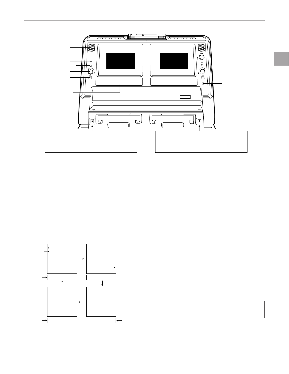
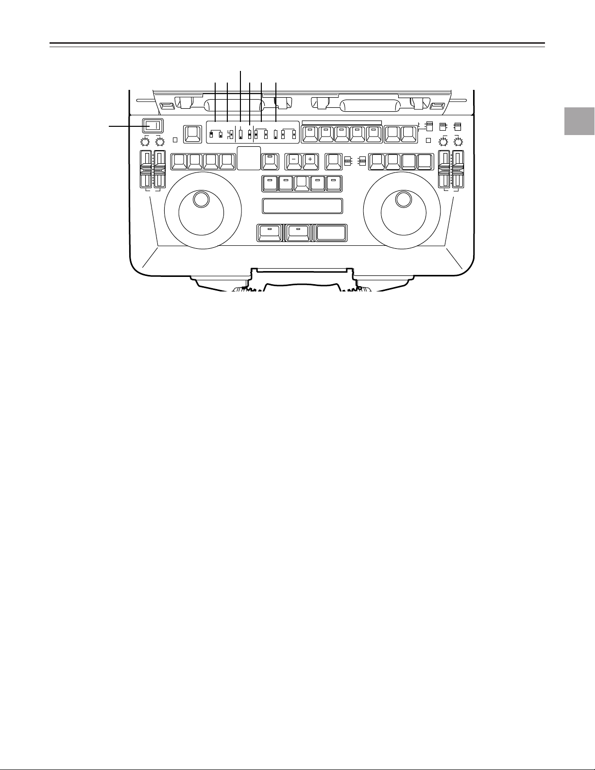
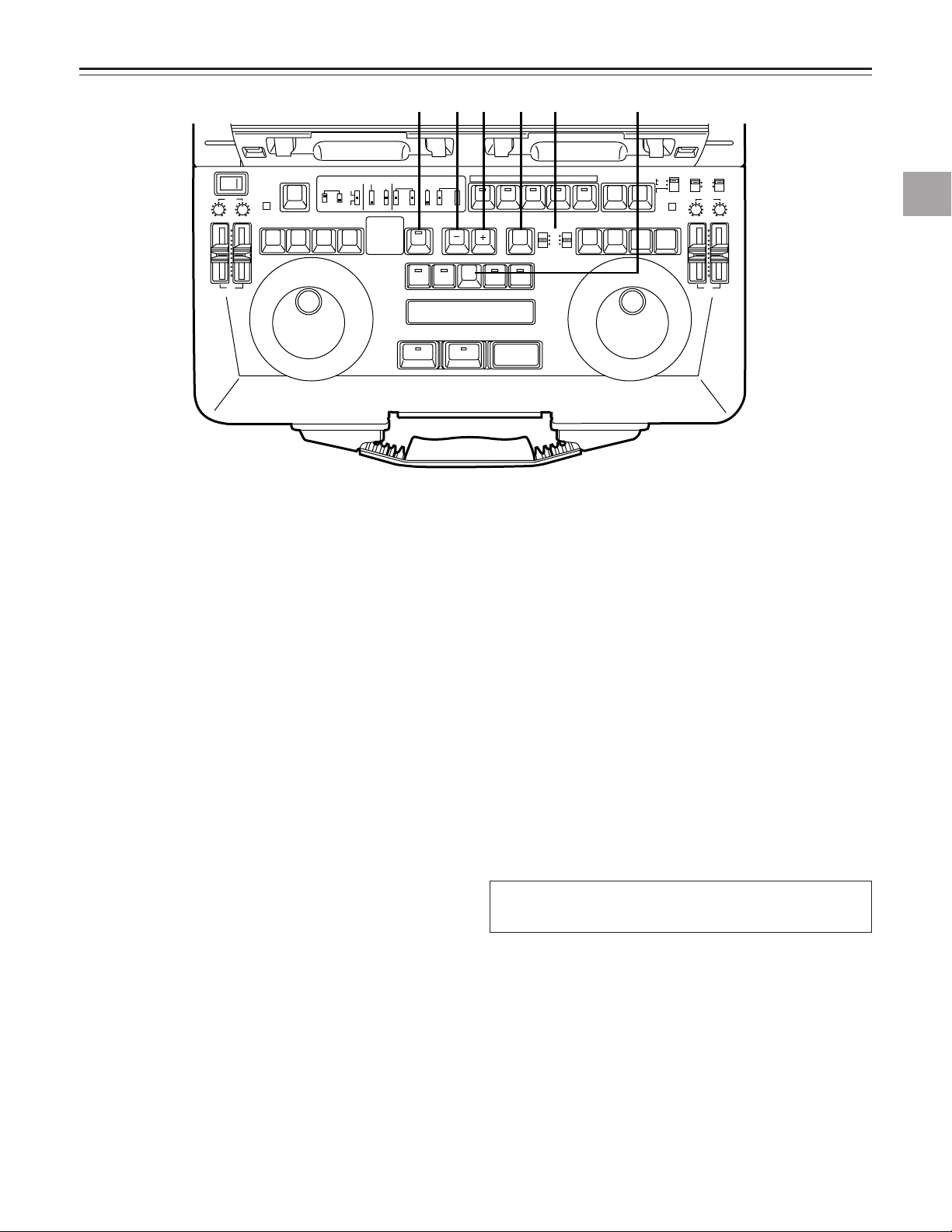
CONTROLS AND THEIR FUNCTIONS
1
Display 1: VTR1
2
3
liquid-crystal
monitor
4
5
[2] Counter display
(see page 6)
VTR 1 VTR 2
EJECT: Press this to eject the tape in VTR1.
The tapes in both VTR1 and VTR2 can be
ejected by pressing this button at the same
time as ALL STOP.
[1] Liquid-crystal monitor section
q Audio monitor speaker
The VTR1 (or VTR2) monitor sound is heard through this
speaker. Depending on the position selected by the
SPEAKER/HEADPHONES switch, the VTR1 and/or
VTR2 sound is selected and output.
w COUNTER/REMAIN switch
This selects the VTR1 display tube contents. When it is
switched between the COUNTER and REMAIN positions,
the on-screen (OSD) display position is switched. (Top,
bottom and OFF)
Each time the switch is pressed, the display is switched
as shown below.
Counter
display
VTR mode
display
Counter
display
TCR 00:00:04:14
SHTL + 0.0
TCR 00:00:04:14 TCR 00:00:04:14
No display
Display 2: VTR2
liquid-crystal
monitor
6
7
EJECT: Press this to eject the tape in VTR2.
The tapes in both VTR1 and VTR2 can be
ejected by pressing this button at the same
time as ALL STOP.
e EXT CHECK button
While this button is held down, the external input of VTR1
can be checked. The level meter of the display section is
set to the fine mode.
r BRIGHTNESS control
This is used to adjust the brightness of the VTR1 liquidcrystal display.
t LCD switch
This controls the power to the VTR1 LCD monitor and
selects the brightness of the backlight.
LIGHT: For making the backlight brighter.
DARK: For making the backlight dimmer.
OFF: For turning off the LCD.
y LEVEL control
This is used to adjust the output level of the built-in
speakers and headphones.
u TOTAL button (for VTR2 only)
While this button is held down, the total editing time from
the edit start point to the current editing program appears
on the display counter.
Controls and their functions
TCR 00:00:04:14
SHTL + 0.0
Counter
display
* The display shown above appears on the LCD monitor only when
set-up item No.001 (LCD SUPER) is set to ON.
TCR 00:00:04:14 01:02
TCR 00:00:04:14
SHTL + 0.0
Remaining
tape
display
The description of the VTR2 display is exactly the same
as that for the VTR1 display.
5
CONTROLS AND THEIR FUNCTIONS
INPUT
REF SCH
INHEDIT REC
SCH CF DV TC UB CTL DF TOTAL REMAIN
CH 1
CH 2
W
SERVO
dB –30– –20 –16 –12 –8 –4 0
1 2 3 5 6 7 8 9 0 q w e r
u
yt4
: Appears during playback at 1× or more times
normal tape speed.
: Appears during fast forwarding operations.
: Appears during playback at –1× normal tape
speed.
: Appears during playback in the reverse direction at
–1× to 0 times normal tape speed.
: Appears during playback in the reverse direction at
–1× or more times normal tape speed.
: Appears during rewinding operations.
: Appears during in the pause/still mode
Hours
A period appears here
in the drop frame mode.
A colon appears here
in the non-drop frame mode.
All the colons are cleared when the user bit is displayed.
When nothing appears here,
the time code cannot be read
(no display either).
Minutes Seconds Frames
: Appears during normal playback or recording.
: Appears during playback at 0 to 1×normal tape
speed.
CH 1
CH 2
▼
The tape is now traveling past a position which is
36% of the entire length of the tape from its beginning.
←10's digit in percentage figure ...3
←1's digit in percentage figure ...6
↑
(Example)
[2] Counter display section
q “Cassette loaded” display
This lights when a cassette has been loaded.
It flashes when STANDBY OFF mode is activated.
w INPUT and SCH lamps
These light when the SCH signal is input from an external
source and SCH is in alignment.
• Only INPUT lights when the SCH signal is input and
SCH is not in alignment.
e REF and SCH lamps
These light when the reference signal is input to the REF
IN connector and SCH is in alignment.
• Only REF lights when the reference signal is input to the
REF IN connector and SCH is not in alignment.
r EDIT REC/REC/REC INH lamps
EDIT REC: This lights when the VTR is in edit recording
mode.
REC: This lights when the VTR is in recording mode.
REC INH: This lights when the VTR is in recording inhibit
mode.
t CF lamp
This lights when the color frame is locked.
y SERVO lamp
This lights when the servo is locked.
u DV lamp
This lights when a cassette recorded using a consumeruse DV machine has been loaded.
i W lamp
This lights when the 16:9 wide screen mode has been
set.
o TC lamp
This lights when the time code data is displayed.
!0 UB lamp
This lights when the user bit is displayed.
!1 CTL lamp
This lights when when control signal (CTL) is displayed.
!2 DF lamp
This lights in drop frame mode.
!33 TOTAL lamp
This lights when the total editing time is displayed.
!4 REMAIN lamp
This lights when the remaining tape is displayed.
!5 Operation modes
!6 Time counter display
!7 Audio level meters
• When the EXT CHECK button is pressed, the meter is
set to the fine mode, the ▼mark is placed at the reference level (–20 dB), and each scale unit represents a 1
dB increment. The REC level can be adjusted by supplying reference level audio signals from an external
source.
• When a blank tape or blank part of a tape is played
back, fast forwarded or rewound, the meter is set to the
tape position display mode so that the current tape travel position can be ascertained.
6
CONTROLS AND THEIR FUNCTIONS
---
-
-
-
-
-
-
-
-
-
-
-
-
-
-
-
-
-
-
-
-
-
-
EJECT
VTR1
POWER
REC
CH1
RESET
REC
DIAG
REMOTE
EXT VTR
LOCAL-
VTR1 VTR2
CONTROL
ON
OFF
REC
INHIBIT
OFF
ON
CH2
PB
AUDIO LEVEL
REW
FF
STOP
STB OFF
TRACK
PLAY STILL
1ST EDIT
BS
EVENT
SPLIT
ASMBL
IN OUT
VTR1 VTR2 VTR1 VTR2
PREROLL
SYNCHRO
7
5
3
CF
ON
OFF
CH1
MIX
CH2
V1
V1•2
V2
SWAP
NORM
MIX
AUDIO
MONITOR
SPEAKER/
HEADPHONES
AUDIO
SWAP
DUMP LOAD
EDL
CLEAR
FS
RECALL
LAST
EDIT
VA1A2TC
PLAY
IN OUT
GO TO
ENTRY / SHIFT
EDIT MODE
COUNTER
CTL
TC
UB
VTR1
EJECT
VTR2
RESET
REC
STORE
STOP
STB OFF
MENU
EDIT
STILL
REW
FF
VTR2
REC
CH1 CH2
OPERATION MODE
VTR2 AUDIO
INPUT SELECT
EDIT
INT
EXT
SEPARATE
CH1 CH2
VTR1
EXT
PB
AUDIO LEVEL
PREVIEW
REVIEW MULTI
AUTO EDIT
ALL STOP
1
2
3 6 7
4
5
[3] Front Keyboard Switches
Controls and their functions
q POWER switch
w REC INHIBIT switch
ON: For inhibiting recording.
OFF: Recording is possible at this position.
Recording with VTR1 is possible only when the
OPERATION MODE switch has been set to SEPARATE.
e CONTROL switch
REMOTE: For controlling the laptop from the external
REMOTE connector (9P).
LOCAL: For controlling the laptop using the controls
on the laptop’s front panel.
EXT VTR: For controlling an external VTR from the
unit’s front panel.
It enables the VTR connected to the 9-pin
connector on the VTR1 side to be operated
by the control buttons of VTR1.
r PREROLL switch
This sets the preroll time to 3, 5 or 7 seconds.
When it is not possible to achieve synchronization, the
preroll time is incremented by one setting. At the 7-second setting, the time remains at 7 seconds even if synchronization is lost.
t SYNCHRO switch
This sets whether synchronization and/or color framing
are to be performed.
CF: Both synchronization and color framing are per-
ON: Synchronization is performed but color framing is
formed.
not performed.
OFF: Synchronization is not performed.
y AUDIO MONITOR switch (for both VTR1 and VTR2)
CH1: The CH1 sound is output.
MIX: The sounds of CH1 and CH2 are mixed and output.
CH2: The CH2 sound is output.
u SPEAKER/HEADPHONES switch
This selects the sound which is output from the speaker
or headphones.
V1:
The sound selected by the AUDIO MONITOR
switch of VTR1 is output (in stereo when the
AUDIO MONITOR switch has been set to the
MIX position).
V1•V2:
The sound by the AUDIO MONITOR switch of
VTR1/VTR2 is output.
Left: Output sound of VTR1
Right: Output sound of VTR2
V2:
The sound selected by the AUDIO MONITOR
switch of VTR2 is output (in stereo when the
AUDIO MONITOR switch has been set to the
MIX position).
• This is valid only when set-up menu item No.711 (AUTO
MONI) has been set to “V1+V2.” When set-up menu
item No.711 (AUTO MONI) has been set to “AUTO,” the
sound of the VTR operated last is automatically output
regardless of the switch position.
• When V1+V2 is selected, and editing or dubbing is performed from VTR1 to VTR2, the sound may be accompanied by an echo effect: this is normal and not indicative of malfunctioning. If this effect is unpleasant, select
V1 or V2, or set AUDIO MONI on the above item to
“AUTO.”
7
CONTROLS AND THEIR FUNCTIONS
---
-
-
-
-
-
-
-
-
-
-
-
-
-
-
-
-
-
-
-
-
-
-
EJECT
VTR1
POWER
REC
CH1
RESET
REC
DIAG
REMOTE
EXT VTR
LOCAL-
VTR1 VTR2
CONTROL
ON
OFF
REC
INHIBIT
OFF
ON
CH2
PB
AUDIO LEVEL
REW
FF
STOP
STB OFF
TRACK
PLAY STILL
1ST EDIT
BS
EVENT
SPLIT
ASMBL
IN OUT
VTR1 VTR2 VTR1 VTR2
PREROLL
SYNCHRO
7
5
3
CF
ON
OFF
CH1
MIX
CH2
V1
V1•2
V2
SWAP
NORM
MIX
AUDIO
MONITOR
SPEAKER/
HEADPHONES
AUDIO
SWAP
DUMP LOAD
EDL
CLEAR
FS
RECALL
LAST
EDIT
VA1A2TC
PLAY
IN OUT
GO TO
ENTRY / SHIFT
EDIT MODE
COUNTER
CTL
TC
UB
VTR1
EJECT
VTR2
RESET
REC
STORE
STOP
STB OFF
MENU
EDIT
STILL
REW
FF
VTR2
REC
CH1 CH2
OPERATION MODE
VTR2 AUDIO
INPUT SELECT
EDIT
INT
EXT
SEPARATE
CH1 CH2
VTR1
EXT
PB
AUDIO LEVEL
PREVIEW
REVIEW MULTI
AUTO EDIT
ALL STOP
w
q
0
9
8
SWAP
CH1 output
connector
CH2 output
connector
NORM
CH2 sound
CH1 sound
CH1, CH2 sound
mixed
CH1, CH2 sound
mixed
CH1 sound
CH2 sound
MIX
i AUDIO SWAP switch (for both VTR1 and VTR2)
This selects the audio output. (It is also effective when an
internal connection is made from VTR1 to VTR2.)
• The SWAP, NORM or MIX sound is not output to the
AUDIO MON OUT connector or HEADPHONES jack.
• The sound which is output from the built-in speakers
and headphones remains unchanged.
o OPERATION MODE switch
INT: In this mode, editing is performed using an internal
connection from VTR1 to VTR2. VTR1 enters the
recording prohibited mode.
EXT: In this mode, editing is performed using an external
analog connection from VTR1 to VTR2. VTR1
enters the recording prohibited mode.
arately.
SEPARATE: In this mode, VTR1 and VTR2 operate sep-
Note:
When editing a tape in VTR1 in the INT mode, the output
signals from the PB VIDEO OUT connector or MONITOR
OUT connector may be affected by vertical dancing, however no problem are posed with editing.
!0 VTR2 AUDIO INPUT SELECT switch
This selects the audio CH1 and CH2 input of VTR2.
VTR1: The audio output signals of VTR1 are supplied to
VTR2.
EXT: The external audio input signals of VTR2 are sup-
plied to VTR2.
Level Controls
!1 REC AUDIO LEVEL controls (for both VTR1 and
VTR2)
CH1: For adjusting the CH1 recording level.
CH2: For adjusting the CH2 recording level.
!2 PB AUDIO LEVEL controls (for both VTR1 and VTR2)
CH1: For adjusting the CH1 playback level.
CH2: For adjusting the CH2 playback level.
8
CONTROLS AND THEIR FUNCTIONS
---
-
-
-
-
-
-
-
-
-
-
-
-
-
-
-
-
-
-
-
-
-
-
EJECT
VTR1
POWER
REC
CH1
RESET
REC
DIAG
REMOTE
EXT VTR
LOCAL-
VTR1 VTR2
CONTROL
ON
OFF
REC
INHIBIT
OFF
ON
CH2
PB
AUDIO LEVEL
REW
FF
STOP
STB OFF
TRACK
PLAY STILL
1ST EDIT
BS
EVENT
SPLIT
ASMBL
IN OUT
VTR1 VTR2 VTR1 VTR2
PREROLL
SYNCHRO
7
5
3
CF
ON
OFF
CH1
MIX
CH2
V1
V1•2
V2
SWAP
NORM
MIX
AUDIO
MONITOR
SPEAKER/
HEADPHONES
AUDIO
SWAP
DUMP LOAD
EDL
CLEAR
FS
RECALL
LAST
EDIT
VA1A2TC
PLAY
IN OUT
GO TO
ENTRY / SHIFT
EDIT MODE
COUNTER
CTL
TC
UB
VTR1
EJECT
VTR2
RESET
REC
STORE
STOP
STB OFF
MENU
EDIT
STILL
REW
FF
VTR2
REC
CH1 CH2
OPERATION MODE
VTR2 AUDIO
INPUT SELECT
EDIT
INT
EXT
SEPARATE
CH1 CH2
VTR1
EXT
PB
AUDIO LEVEL
PREVIEW
REVIEW MULTI
AUTO EDIT
ALL STOP
1
2
3
4
5
7
6
Controls and their functions
[4] Player/Recorder Control Section
q REC button (for recorder control section only)
To set the recorder VTR manually to the recording mode,
press this button and the PLAY button together.
Recording is possible on the VTR1 only if the OPERATION MODE switch of VTR1 is set to “SEPARATE.”
DIAG (SHIFT+DIAG): Press these buttons to display the
DIAG menu.
w RESET button
• This is used to reset the CTL counter on the VTR1 display section or to reset an edit point.
• When it is pressed together with the IN or OUT button,
the registered IN point or OUT point is deleted.
[5] VTR Control Section (for both
e PLAY (STOP) button
Press this button to set the VTR to the playback mode.
STOP (SHIFT+PLAY): Press these buttons to set the
VTR to the stop mode.
r STILL (STB OFF) button
STILL: Press this button to set the VTR to the still picture
mode.
STBOFF (SHIFT+STILL): Press these buttons to release
the standby mode in the still-picture or stop mode.
t REW button (*)
Press this to rewind the tape. The tapes in both VTR1
and VTR2 can be rewound by pressing this button at the
same time as ALL STOP.
y FF (TRACK: VTR1 only) button (*)
FF: Press this to fast forward the tape.
TRACK (SHIFT+FF, VTR1 only): Press this to establish
the TRACK mode. Refer to the section on the track functions.
u Search dial button
This controls the tape travel. Use it for locating edit points
or for playback. In the “out” position, the dial is set to the
shuttle mode; in the “in” position, it is set to the jog mode.
Each time the dial is pressed, the selection is toggled
between these two modes.
(*) The tape stops traveling when the REW and FF buttons
are pressed together.
VTR1 and VTR2)
9
CONTROLS AND THEIR FUNCTIONS
---
-
-
-
-
-
-
-
-
-
-
-
-
-
-
-
-
-
-
-
-
-
-
EJECT
VTR1
POWER
REC
CH1
RESET
REC
DIAG
REMOTE
EXT VTR
LOCAL-
VTR1 VTR2
CONTROL
ON
OFF
REC
INHIBIT
OFF
ON
CH2
PB
AUDIO LEVEL
REW
FF
STOP
STB OFF
TRACK
PLAY STILL
1ST EDIT
BS
EVENT
SPLIT
ASMBL
IN OUT
VTR1 VTR2 VTR1 VTR2
PREROLL
SYNCHRO
7
5
3
CF
ON
OFF
CH1
MIX
CH2
V1
V1•2
V2
SWAP
NORM
MIX
AUDIO
MONITOR
SPEAKER/
HEADPHONES
AUDIO
SWAP
DUMP LOAD
EDL
CLEAR
FS
RECALL
LAST
EDIT
VA1A2TC
PLAY
IN OUT
GO TO
ENTRY / SHIFT
EDIT MODE
COUNTER
CTL
TC
UB
VTR1
EJECT
VTR2
RESET
REC
STORE
STOP
STB OFF
MENU
EDIT
STILL
REW
FF
VTR2
REC
CH1 CH2
OPERATION MODE
VTR2 AUDIO
INPUT SELECT
EDIT
INT
EXT
SEPARATE
CH1 CH2
VTR1
EXT
PB
AUDIO LEVEL
PREVIEW
REVIEW MULTI
AUTO EDIT
ALL STOP
8
1
2 3 4 5 6 7
[6] Edit Mode Setting Section
q ASMBL button
Press this to perform assemble editing. Check that the
button LED has lighted.
1ST EDIT (SHIFT+ASMBL): With VTR2, the registered
position for the 1ST EDIT preset value is automatically
set to -23 seconds. For details, refer to set-up menu item
No. 312 (1ST EDIT DUR).
w V button/lamp
For inserting video signals, press this button. Check that
its lamp is lighted up.
e A1 button
Press this to insert the audio CH1 signals. Check that the
button LED has lighted.
DUMP (SHIFT+A1): Press this to download EDL data to
an external device (such as a personal computer).
r A2 button
Press this to insert the audio CH2 signals. Check that the
button LED has lighted.
LOAD (SHIFT+A2): Press this to upload EDL data from
an external device (such as a personal computer).
t TC button
Press this to insert the time code. Check that the button
LED has lighted.
EDL (SHIFT+TC): Press this to display the editing list on
the LCD screen.
y REC (STORE) button
REC: To set the VTR manually to the recording mode,
press this button and the PLAY button together.
When the REC button is pressed while the REC INHIBIT
switch is at OFF, the VTR2 video and audio CH1 and
CH2 will be set to the E-E mode while the button is held
down.
STORE (SHIFT+REC): Press these buttons to set the
VTR1 (playback) or VTR2 (recording) edit points and
store the edit data in the internal memory.
The EVENT counter is simultaneously incremented.
When the set-up operations are performed, the data
which has been set is saved in the set-up memory.
u EDIT (MENU) button
EDIT: Press this button to establish the E-E mode in
accordance with the edit mode. While it is held down, the
VTR2 video and audio input signals are output without
being recorded in accordance with the edit mode. To conduct a recording, press this button together with the PLAY
button in the VTR2 control section, while VTR2 is in the
playback mode.
MENU (SHIFT+EDIT): Press these buttons to perform
dial menu set-up.
i RESET button
• This resets the CTL counter on the VTR2 display section.
• When the IN or OUT button is pressed together with the
RESET button, the registered IN or OUT point is
cleared.
10
CONTROLS AND THEIR FUNCTIONS
---
-
-
-
-
-
-
-
-
-
-
-
-
-
-
-
-
-
-
-
-
-
-
EJECT
VTR1
POWER
REC
CH1
RESET
REC
DIAG
REMOTE
EXT VTR
LOCAL-
VTR1 VTR2
CONTROL
ON
OFF
REC
INHIBIT
OFF
ON
CH2
PB
AUDIO LEVEL
REW
FF
STOP
STB OFF
TRACK
PLAY STILL
1ST EDIT
BS
EVENT
SPLIT
ASMBL
IN OUT
VTR1 VTR2 VTR1 VTR2
PREROLL
SYNCHRO
7
5
3
CF
ON
OFF
CH1
MIX
CH2
V1
V1•2
V2
SWAP
NORM
MIX
AUDIO
MONITOR
SPEAKER/
HEADPHONES
AUDIO
SWAP
DUMP LOAD
EDL
CLEAR
FS
RECALL
LAST
EDIT
VA1A2TC
PLAY
IN OUT
GO TO
ENTRY / SHIFT
EDIT MODE
COUNTER
CTL
TC
UB
VTR1
EJECT
VTR2
RESET
REC
STORE
STOP
STB OFF
MENU
EDIT
STILL
REW
FF
VTR2
REC
CH1 CH2
OPERATION MODE
VTR2 AUDIO
INPUT SELECT
EDIT
INT
EXT
SEPARATE
CH1 CH2
VTR1
EXT
PB
AUDIO LEVEL
PREVIEW
REVIEW MULTI
AUTO EDIT
ALL STOP
1 3 4 2 5 6
[7] Automatic Editing Control Section
Controls and their functions
q SPLIT button
For split editing, press this so that the button LED lights,
and then set the edit IN point to be split. Refer to set-up
menu item No.311 (SPLIT EDIT).
w LAST EDIT (CLEAR) button
LAST EDIT: This button accesses the previously pre-
viewed contents. (It alternately accesses two sets of contents whose preview has been completed.)
CLEAR (SHIFT+LAST EDIT): These buttons delete the
registered event. The “d” display appears for EDL.
e – (BS) Minus trim button
–: When the IN or OUT point which has been input is to
be returned by one frame, this trim button is pressed
while the IN or OUT button is pressed. To use this
function continuously, keep pressing the buttons. To
set further back both the IN and OUT points simultaneously for editing, press this trim button while the IN and
OUT buttons are pressed.
BS (SHIFT+“–”): These buttons access the previous edit.
Keep pressing the button to execute the function continuously.
r + (FS) Plus trim button
+: When the IN or OUT point which has been input is to
FS (SHIFT+“+”): These buttons access the last event.
be advanced by one frame, this trim button is pressed
while the IN or OUT button is pressed. To use this
function continuously, keep pressing the buttons. To
advance both the IN and OUT points simultaneously
for editing, press this trim button while the IN and OUT
buttons are pressed.
Keep pressing the button to execute the function continu-
ously.
t COUNTER switchs
These switches select the counter reference for VTR1
and VTR2.
CTL: At this switch position, the CTL pulse count after
resetting appears on the counter display. It is reset
by the RESET button.
TC: The time code (absolute value) which has been
read appears at this position. It is not reset even if
the RESET button is pressed.
UB: The user bit which has been read appears at this
position.
y GO TO/RECALL button
GO TO: To check the IN or OUT point image, press the
IN or OUT button while holding down the GO TO button.
In the audio split edit mode, the audio IN point is
searched when the IN button is pressed.
RECALL (SHIFT+GO TO): These buttons re-register an
event which was deleted in the EDL mode. The “d” display changes to “no display.”
This button does not work when the SEPARATE MODE
switch has been set to SEPARATE.
11
CONTROLS AND THEIR FUNCTIONS
---
-
-
-
-
-
-
-
-
-
-
-
-
-
-
-
-
-
-
-
-
-
-
EJECT
VTR1
POWER
REC
CH1
RESET
REC
DIAG
REMOTE
EXT VTR
LOCAL-
VTR1 VTR2
CONTROL
ON
OFF
REC
INHIBIT
OFF
ON
CH2
PB
AUDIO LEVEL
REW
FF
STOP
STB OFF
TRACK
PLAY STILL
1ST EDIT
BS
EVENT
SPLIT
ASMBL
IN OUT
VTR1 VTR2 VTR1 VTR2
PREROLL
SYNCHRO
7
5
3
CF
ON
OFF
CH1
MIX
CH2
V1
V1•2
V2
SWAP
NORM
MIX
AUDIO
MONITOR
SPEAKER/
HEADPHONES
AUDIO
SWAP
DUMP LOAD
EDL
CLEAR
FS
RECALL
LAST
EDIT
VA1A2TC
PLAY
IN OUT
GO TO
ENTRY / SHIFT
EDIT MODE
COUNTER
CTL
TC
UB
VTR1
EJECT
VTR2
RESET
REC
STORE
STOP
STB OFF
MENU
EDIT
STILL
REW
FF
VTR2
REC
CH1 CH2
OPERATION MODE
VTR2 AUDIO
INPUT SELECT
EDIT
INT
EXT
SEPARATE
CH1 CH2
VTR1
EXT
PB
AUDIO LEVEL
PREVIEW
REVIEW MULTI
AUTO EDIT
ALL STOP
w
9 0 q
7 8
u IN button (for both VTR1 and VTR2)
Press this button while holding down the ENTRY button
to register the IN point of the player or recorder.
Press it alone to check the IN point. While it is held down,
the IN point appears on the display. To display the editing
duration, press the IN and OUT buttons together.
“– –:– –:––:– –” is displayed when the edit IN and OUT
points are not registered.
i OUT button (for both VTR1 and VTR2)
Press this button while holding down the ENTRY button
to register the OUT point of the player or recorder.
Press it alone to check the OUT point. While it is held
down, the OUT point appears on the display. To display
the editing duration, press the OUT and IN buttons
together.
o PREVIEW/REVIEW button
PREVIEW: To conduct an editing rehearsal, press this
button and light up its lamp.
REVIEW (SHIFT+PREVIEW): When reviewing the edited
block, press this button and light up its lamp.
and light up its lamp.
!0 AUTO EDIT/MULTI button
AUTO EDIT: To start automatic editing, press this button
MULT (SHIFT+AUTO EDIT): Press these buttons to edit
two or more events in succession from the current edit in
the EDL mode. Editing is executed automatically until
either the editing of the last event is completed or the ALL
STOP button is pressed to forcibly terminate the editing.
!1 ALL STOP button
When this button is pressed during preview, automatic
editing or review, the ongoing operation is stopped.
However, only VTR2 is stopped when the OPERATION
MODE switch has been set to “SEPARATE.”
When the button is pressed together with the CLEAR button, all the events in the EDL are deleted, and the event
number is set to “n01.”
!2 Event number display
Up to 100 (01 to 99, 00) edit data are controlled inside the
laptop.
Two-digit event numbers appear on this display.
Depending on the edit status, “n” or “d” appears in front of
the event number.
n: A new event which is not registered in the EDL.
d: An event which was deleted from the EDL.
No display: An event which is registered in the EDL.
FULL: All 100 events have been registered.
–: When the laptop is operated by remote control or
when the OPERATION MODE switch has been set to
“SEPARATE.”
rSt: When the power was turned on or when resetting
was performed.
12
CONTROLS AND THEIR FUNCTIONS
VIDEO
LEVEL
SET UP
HUE
CHROMA
LEVEL
H
FINE
COARSE
SYSTEM
SC
12345
HEADPHONES
①
②
Controls and their functions
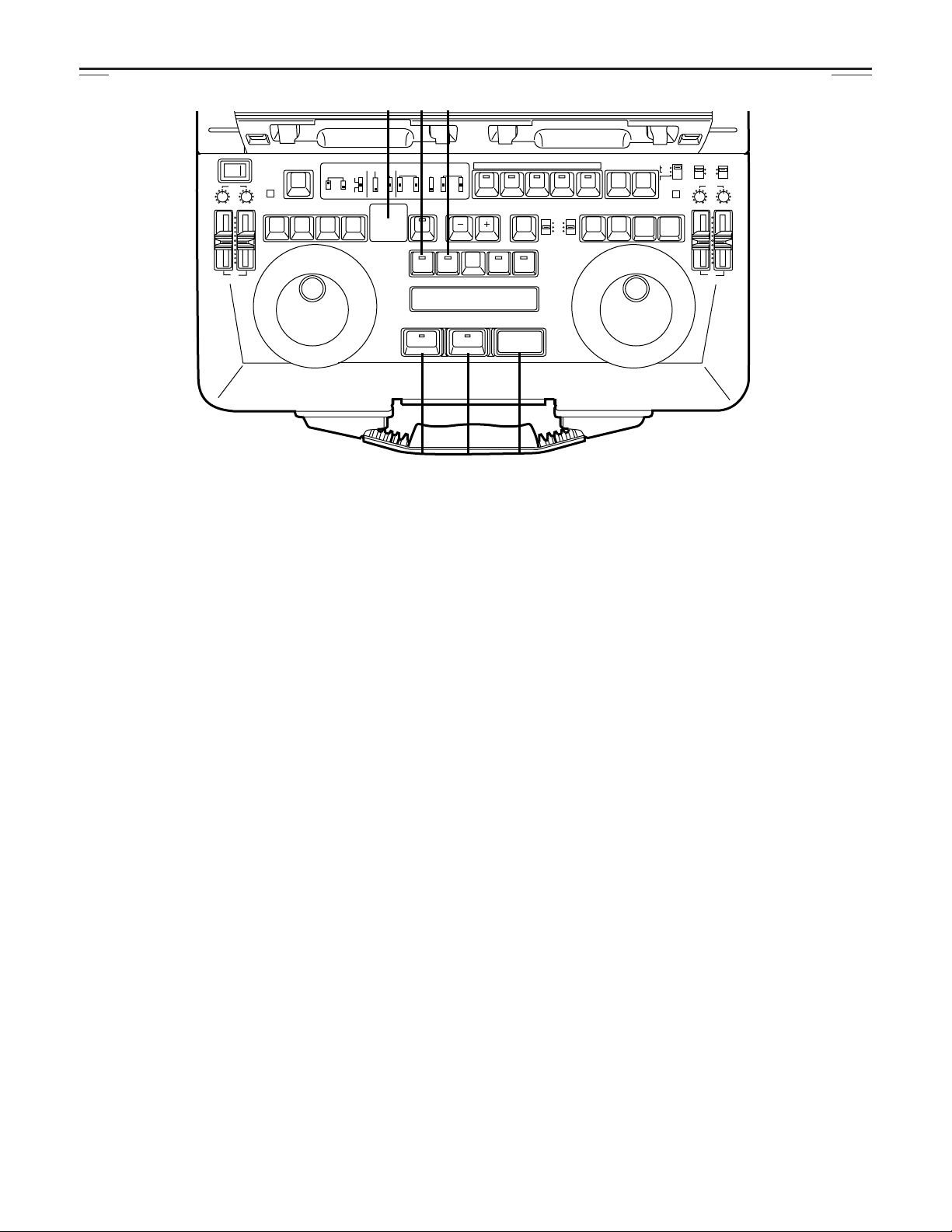
[8] Side Panel Section (for both
VTR1 and VTR2)
Signals conveyed via an internal connection cannot be
adjusted.
q VIDEO LEVEL control
This is used to adjust the video level of the VTR’s video
output.
w SET UP control
This is used to adjust the set-up level of the VTR’s video
output signals.
e HUE control
This is used to adjust the hue of the VTR’s video output
signals.
r CHROMA LEVEL control
This is used to adjust the chroma level of the VTR’s video
output signals.
t SYSTEM controls
H: This is used to adjust the system phase in SC period
increments.
SC FINE: This is used to adjust the SCH phase only; the
SC phase is changed (the H phase remains
unchanged).
SC COARSE: This is used to adjust the SCH phase in
90-degree increments (the H phase
remains unchanged).
[9] Front Section
q Headphone jack (Mini stereo)
• When the headphones are plugged into this jack, the
sound will no longer be heard through the built-in speaker.
• Adjust the headphones output level using the LEVEL
control in the LCD monitor section.
[10] Top Section
w VTR operation display LED
This indicator allows the user to check the operation status of the VTR even when the display is closed.
Off:
Lights:
Flashes (at approx. 1-second intervals):
Flashes (at approx. 0.5-second intervals):
Flashes (at approx. 0.25-second intervals):
Indicates the power OFF status.
Indicates that the power is on and the tape is
stopped.
Indicates that a tape is traveling in one of the
VTRs.
Indicates that tapes are traveling in both of the
VTRs.
Indicates the auto OFF status.
13
CONTROLS AND THEIR FUNCTIONS
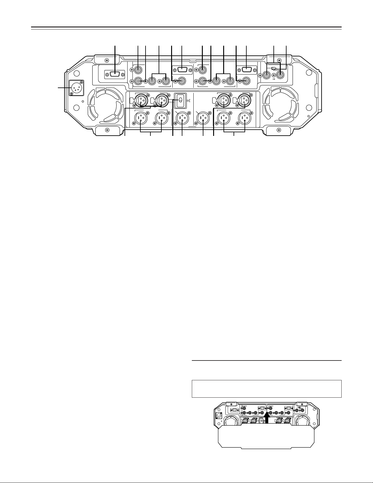
DC IN
VIDEO IN
VIDEO/Y
P
B
EDL
VIDEO OUT
AUDIO IN
CH 1
V
T
R
2
V
T
R
2
CH 1
CH 2
P
R
REMOTE
PB VIDEO OUT
AUDIO OUT
AUDIO MON OUT
AUDIO MON OUT
VIDEO MON /TC OUT
CH 1
CH 2
MIC
LINE
VIDEO IN
VIDEO/Y
P
B
AUDIO IN
AUDIO OUT
VIDEO MON /TC OUT
TC IN
REF IN
REF
THROUGH
75ΩAUTO
CH 1
V
T
R
1
V
T
R
1
CH 2
CH 2
P
R
REMOTE
1
2
2ry 5
9q7
6456q8we3
07
t
DC IN
VIDEO IN
VIDEO/Y
P
B
EDL
VIDEO OUT
AUDIO IN
CH 1
V
T
R
2
V
T
R
2
CH 1
CH 2
P
R
REMOTE
PB VIDEO OUT
AUDIO OUT
AUDIO MON OUT
AUDIO MON OUT
VIDEO MON /TC OUT
CH 1
CH 2
MIC
LINE
VIDEO IN
VIDEO/Y
P
B
AUDIO IN
AUDIO OUT
VIDEO MON /TC OUT
TC IN
REF IN
REF
THROUGH
75ΩAUTO
CH 1
V
T
R
1
V
T
R
1
CH 2
CH 2
P
R
REMOTE
Connector Section (for both VTR1 and VTR2)
q DC IN socket (XLR 4P)
DC power input socket.
The AC adaptor AJ-B75 (optional accessory) must be
used to supply the power. The unit’s operation cannot be
guaranteed if any other power supply is used instead.
w VIDEO IN connector (BNC)
The analog composite signal is supplied to this connector.
e VIDEO/Y OUT connector (BNC) (VTR2 only)
The analog composite signals are output from this connector.
The Y (luminance) signal is output when CMPNT has
been set for set-up menu item No.806 (V OUT SEL).
r PB VIDEO/Y OUT connector (BNC) (VTR1 only)
The analog composite signals are output from this connector during playback only (E-E signals are not output).
The Y (luminance) signal is output during playback only
when CMPNT has been set for set-up menu item No.806
(V OUT SEL). (E-E signals are not output).
t VIDEO MON OUT/TC OUT connector (BNC)
The video monitor signals are output from this connector.
The time code signal is output when TCOUT1 or TCOUT2
has been set for set-up menu item No.514 (TC OUT).
y REMOTE connector (D-SUB, 9P, female)
This is the RS-422A interface remote connector. It
enables the unit to be operated from an external controller. The VTR1 remote connector is switched to a
REMOTE OUT connector by setting the CONTROL
switch on the keyboard to EXT VTR so that an external
VTR can be controlled using the VTR1 controls on this
unit.
u AUDIO IN connectors (CH1/CH2) (XLR ×2)
The analog audio signals are supplied to these connectors.
i CH2 INPUT level switch
Used to select the analog audio input signal CH2 level.
LINE: Line input (+4/0/–20 dBu)
MIC: MIC input (–50 dBu)
o AUDIO OUT connectors (CH1/CH2) (XLR ×2) (for VTR2
only)
Analog audio signals are output from these connectors.
!0 PB AUDIO OUT connectors (CH1/CH2) (XLR ×2) (for
VTR1 only)
The analog audio signals are output from these connectors
only during playback. (The E-E signals are not output.)
!1 AUDIO MON OUT connector (XLR)
The audio monitor signal is output from this connector.
!2 REF VIDEO IN/TC IN connectors (BNC ×2)
Analog composite signals are supplied to these connectors.
These are loop-through connectors provided with automatic 75-ohm termination.
!3 REF THRU/TC IN selector switch
This selects whether the right-hand REF VIDEO IN/TC IN
connector !2 is to be used as the REF loop-through connector or as the TC input connector.
• REF THRU: The connector is used as the REF loopthrough connector. 75-ohm termination is provided automatically.
• TC IN: The connector is used as the time code input
connector. The left-hand REF VIDEO IN connector !2
still serves as the REF input while the loop-through
function is canceled, and the 75-ohm termination is fixed
at ON.
!4 VIDEO OUT connector (P
B and PR signals among the analog component sig-
The P
B OUT/PR OUT) (BNC)
nals are output from this connector.
!5 PB VIDEO OUT connector (P
B and PR signals among the analog component sig-
The P
B OUT/PR OUT) (BNC)
nals are output from this connector during playback only.
!6 EDL connector (D-SUB, 9P, male)
This is used to connect to a personal computer, etc. to
download and/or upload the edit list data.
It is also used to connect the audio memory unit which is
available as an optional accessory.
Before carrying the main unit, be sure to attach the accessory
connector cover.
Do not turn on the unit’s power with the connector cover
attached.
14
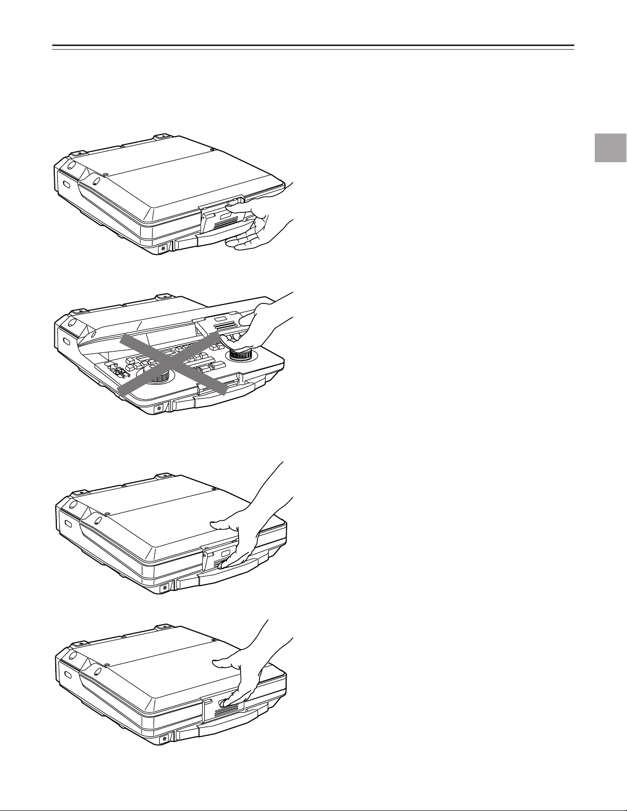
OPENING AND CLOSING THE LAPTOP
HEADPHONES
0 (HEADPHONES
VTR1
VTR2
HEADPHONES
HEADPHONES
Pull the lever and release the lock.
Do not take hold of the lever and use it to open the laptop.
Opening and closing the laptop
Close the laptop while pushing the bottom of the lever, as
shown in the figure on the left.
! Push the bottom of the lever.
@ Push up the lever.
Notes:
1.
Take care not to catch your fingers in the cover while
opening or closing it.
2.
Take care not to use this unit on bedding or a carpet.
15
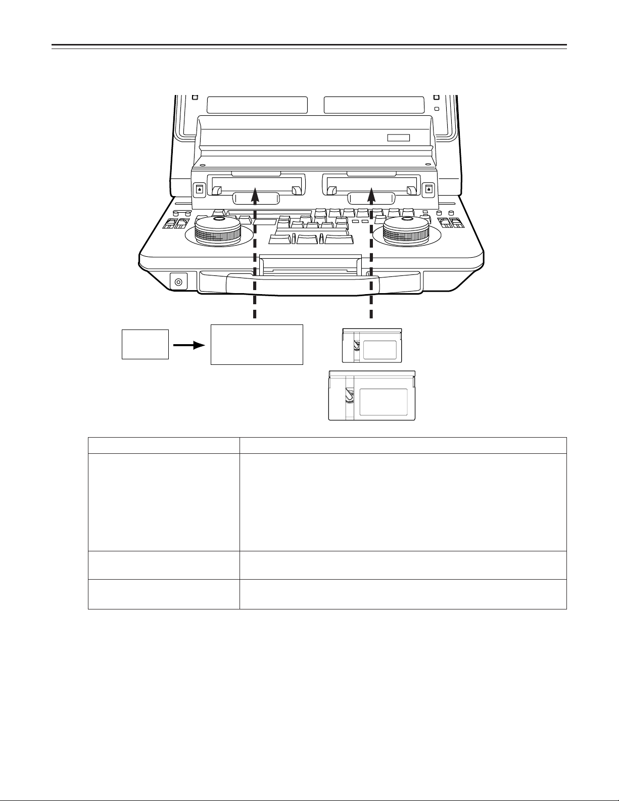
COMPATIBLE TAPES
M cassette
DV tape
(S cassette)
Casette adaptor
(AJ-CS750P, option)
L cassette
VTR 1 VTR 2
Align the cassette tape with the center of the loading slot, and push it in gently. It is then loaded automatically.
Cassette type
Consumer-use DV cassette
(S cassette)
This is exclusively designed for use in consumer-use cassette camera/recorder
units. It can be used with the laptop for playback only if the AJ-CS750P
Description
cassette adaptor (option) is obtained.
If a consumer-use cassette tape is to be used, it must first be loaded into the
AJ-CS750P adaptor (optional accessory).
Use of Panasonic consumer DV cassette tapes is recommended.
Ensure that inserting such a tape directly without using the cassette adaptor
may cause trouble.
M cassette
L cassette
Recording/playback tape with a maximum length of 66 minutes
(AJ-P12MP, AJ-P24MP, AJ-P33MP, AJ-P46MP, AJ-P66MP)
Recording/playback tape with a maximum length of 126 minutes
(AJ-P34LP, AJ-P66LP, AJ-P94LP, AJ-P126LP)
<Precautions for playing back consumer-use DV tapes/DVCAM tapes>
• Consumer-use tapes can be used for playback only.
• Use tapes specially designed for DVCPRO applications with this unit. However, if DV tapes or DVCAM tapes are to be used in
the playback mode, it is recommended that playback be limited to as short a period of time as possible.
• Tapes recorded in the LP mode cannot be played back.
• Since consumer-use tapes cannot be used for recording, the laptop’s functions related to recording as well as its REC and
other operations are disabled.
• Consumer tape FF/REW speed is VTR limited to ±32X. Slow motion playback is not possible with consumer cassette tape.
• In order to protect the tape, the maximum STILL TIMER for consumer tape is 10 seconds, and the available time for leaving
the tape in STILL mode is set at 1 minute.
• The read disable display for the time code may sometimes appear while consumer-use tape is being used in the search, slow
motion or still mode.
16
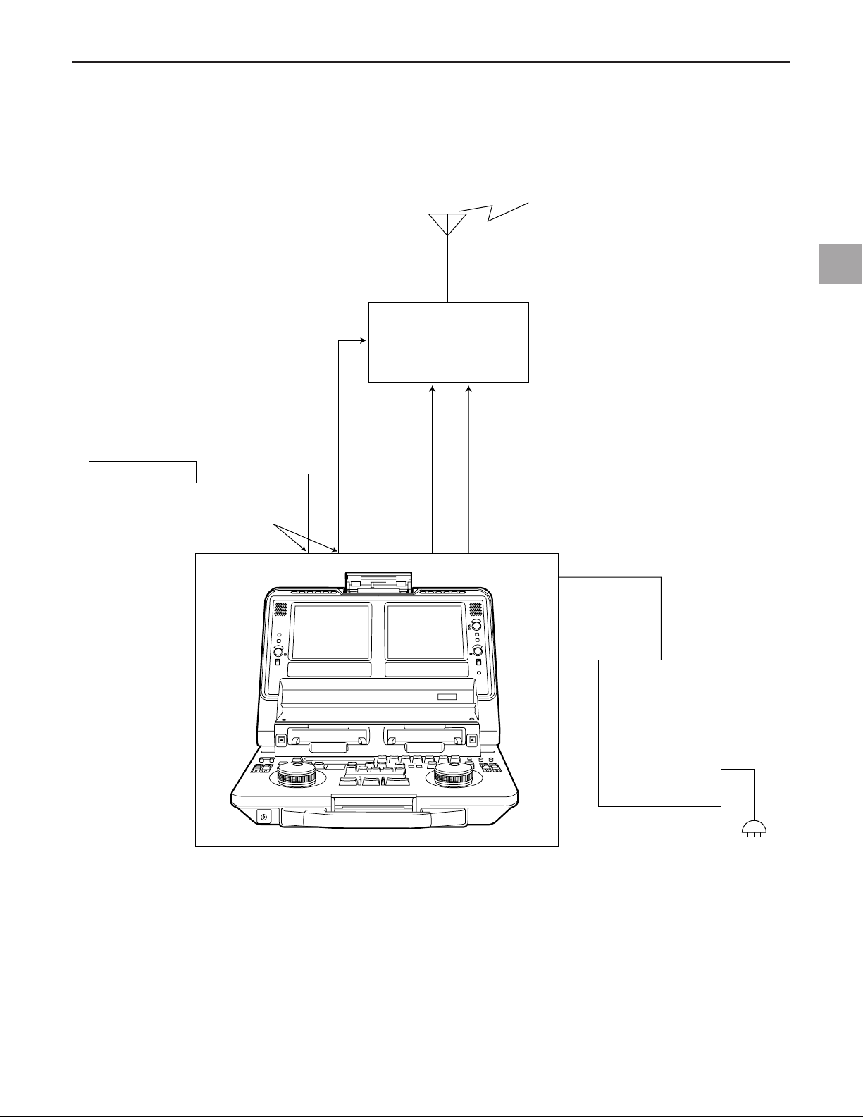
SYSTEM CONNECTIONS
Microwave
transmitter
VIDEO OUT
connector
(OPERATION MODE switch: SEPARATE)
DC IN
DC OUT
AC adaptor
AJ-B75 (option)
AUDIO OUT
CH1/CH2
connector
REF
VIDEO IN
connector
Reference signal
AC adaptor
VTR 1 VTR 2
Connections for transmission
System connections
17
SYSTEM CONNECTIONS
VIDEO IN VIDEO IN
VTR1 VTR2
Switch settings:
OPERATION MODE
VTR1 IN SEL
TC MODE
: SEPARATE
: V2 V+A
: VTR1;
: VTR2;
User preference (P-REC, P-FREE)
VTR1 TC
(Time codes synchronized on both
VTRs)
Switch settings:
OPERATION MODE
VTR1 IN SEL
TC MODE
: SEPARATE
: V1 IN
: VTR1;
: VTR2;
User preference (P-REC, P-FREE)
VTR1 TC
(Time codes synchronized on both
VTRs)
AJ-LT85
VIDEO IN
VTR1 VTR2
AJ-LT85
System applications
■ Backup recording using 2 VTRs
1. Recording the same signal on 2VTRs
2. Recording different signals on 2 VTRs
18
SYSTEM CONNECTIONS
Switch setting
OPERATION MODE
PLAY DELAY
Refer to the items regarding the various editing controller
settings (included) for more information.
:EXT
:VTR1;
VTR2;04
VIDEO INPB VIDEO
OUT
VTR1 VTR2
AJ-LT85
Effector
Editing controller
REF
REF
9P 9P
REF
System applications
■ Using the unit with an external effector or controller switch settings
System connections
<Notes>
• VTR1 cannot be used as the editing recorder.
• Slow motion editing is not supported.
19
SYSTEM CONNECTIONS
VIDEO OUTPB VIDEO
OUT
VTR1 VTR2
AJ-LT85 RECORDER
Editing controller
Switcher
REF
REF
REF
REF
9P 9P
Switch setting
OPERATION MODE
PLAY DELAY
Refer to the items regarding the various
editing controller settings (included) for
more information.
:SEPARATE
:VTR1;
VTR2;00
System applications
■ Using two VTRs as source units for AB roll editing
<Note>
Slow motion editing is not supported.
20
System applications
Switch settings
CONTROL: EXT VTR
PLAY DELAY: VTR1:0
VTR2: 4
VIDEO
IN
VIDEO
OUT
AUDIO
IN
AUDIO
OUT
VTR1 VTR2
AJ-LT85External VTR
9P 9P
Switch settings
CONTROL: EXT VTR
VTR1 IN SEL (set-up menu item No.105): V2 A
VIDEO
IN
VIDEO
IN
VIDEO
OUT
VIDEO
OUT
AUDIO
IN
AUDIO
OUT
VTR1 VTR2
AJ-LT85
External VTR
9P 9P
(Superimpose)
■ When using an external VTR as the editing source unit
• The external VTR can be operated using the VTR1 control buttons of this unit.
• Set the CONTROL switch on the keyboard panel to EXT VTR.
Regardless of the positions of the OPERATION MODE and AUDIO INPUT SELECT switches, the signals connected to the
VTR2’s VIDEO IN and AUDIO IN connectors will be supplied.
System connections
<Notes>
• It is necessary to change the PLAY DELAY setting when certain types of external VTRs are used.
• The external VTR’s signals can be checked on the LCD monitor of VTR1 and through its speaker when V2 V+A is set for setup menu item No.105 (VTR1 IN SEL).
• None of VTR1’s on-screen displays (counter, etc.) can be shown when the CONTROL switch is set to the EXT VTR mode.
However, these displays can be shown on the screen of VTR1 using the connections and settings outlined below when an
external VTR with a superimpose display function is used.
• The VTR1’s INPUT and REF displays do not appear when the CONTROL switch is set to the EXT VTR mode.
21
SET-UP MENU OPERATIONS
---
-
-
-
-
-
-
-
-
-
-
-
-
-
-
-
-
-
-
-
-
-
-
EJECT
VTR1
POWER
REC
CH1
RESET
REC
DIAG
REMOTE
EXT VTR
LOCAL-
VTR1 VTR2
CONTROL
ON
OFF
REC
INHIBIT
OFF
ON
CH2
PB
AUDIO LEVEL
REW
FF
STOP
STB OFF
TRACK
PLAY STILL
1ST EDIT
BS
EVENT
SPLIT
ASMBL
IN OUT
VTR1 VTR2 VTR1 VTR2
PREROLL
SYNCHRO
7
5
3
CF
ON
OFF
CH1
MIX
CH2
V1
V1•2
V2
SWAP
NORM
MIX
AUDIO
MONITOR
SPEAKER/
HEADPHONES
AUDIO
SWAP
DUMP LOAD
EDL
CLEAR
FS
RECALL
LAST
EDIT
VA1A2TC
PLAY
IN OUT
GO TO
ENTRY / SHIFT
EDIT MODE
COUNTER
CTL
TC
UB
VTR1
EJECT
VTR2
RESET
REC
STORE
STOP
STB OFF
MENU
EDIT
STILL
REW
FF
VTR2
REC
CH1 CH2
OPERATION MODE
VTR2 AUDIO
INPUT SELECT
EDIT
INT
EXT
SEPARATE
CH1 CH2
VTR1
EXT
PB
AUDIO LEVEL
PREVIEW
REVIEW MULTI
AUTO EDIT
ALL STOP
EDIT button
RESET button
SHIFT button
The set-up of items other than those set using the selector switches are set on the on-screen menu using the time counter display and search dial.
To perform settings with the on-screen menu, press the MENU (SHIFT+MENU) buttons to establish the set-up mode. The setting contents now appear on the display, and the data settings are stored in the laptop’s memory.
To transfer the laptop from the regular mode to the set-up menu mode, press the SHIFT and EDIT buttons together. (This cannot be done by remote control, or when editing or recording.)
To change a setting:
! Set the laptop to the jog mode.
Remember that this procedure cannot be performed in the shuttle mode.
@ Turn the dial and select the item to be set. (The asterisk “*” moves.)
# While holding down the SHIFT button, turn the dial clockwise or counterclockwise to change the value.
When the IN or OUT button is pressed while the SHIFT button is held down, the setting contents are decremented by IN and
incremented by OUT.
If the 1ST EDIT, TC PRESET or UB PRESET item is to be selected, operation moves to the column on the left or right by
pressing the FF or REW button while the SHIFT button is held down.
• “TC PRESET” and “UB PRESET” can be selected when set-up menu item No.507 (TC MODE) has been set to “P-REC” or
“P-FREE.”
To view the menu page by page:
Press the FF or REW button.
Operation moves to the next page when the FF button is
pressed; it moves to the previous page when the REW button
is pressed. (The cursor moves to the first item in each group
of 100.)
To store a setting in the memory:
Press the REC button while the SHIFT button is held down.
To return to the regular mode from the set-up menu
mode:
Press the EDIT button while the SHIFT button is held down.
User default settings and factory settings
This unit has a memory in which the settings can be entered
by the user. The user can enter specific settings, and these
settings can be called altogether.
The factory settings can be restored after using the user settings.
TC PRESET and UB PRESET are not entered or called.
■ To enter changed settings into the user default setting
memory
• Press the MENU (SHIFT + EDIT) button to establish the
set-up menu mode.
• Change to the desired settings. (Refer to the above section on how to change the settings.)
• Press the RESET button of VTR2 to display the default
setting screen.
• Press the STORE (SHIFT + REC) button to enter the settings.
■ To return changed settings to the user default settings
(loading from the user default setting memory)
• Press the MENU (SHIFT + EDIT) button to establish the
set-up menu mode.
• Press the RESET button of VTR2 to display the default
setting screen.
• Press the FF button of VTR2.
■ To return changed settings to the factory settings
(resetting)
• Press the MENU (SHIFT + EDIT) button to establish the
set-up menu mode.
• Press the RESET button of VTR2 to display the default
setting screen.
• When the PLAY button of VTR2 is pressed, all the items
are reset.
When the STILL button of VTR2 is pressed, all the items
except for SYSTEM are reset.
When the REW button of VTR2 is pressed, the resetting
is canceled.
22

DETAILED DESCRIPTION OF SET-UP MENUS
BASIC
Item Setting
Description of setting
No. Item No. Item
000 DISPLAY SEL 0000 TIME
0001 T&STA
0002 T&RT
0003 T&YMD
0004 T&MDY
0005 T&DMY
This sets the contents of the MONITOR OUT connector and liquid-crystal
monitor superimposed display.
0: Displays the counter value only.
1: Displays the counter value and operation mode.
2: The counter value and shooting time are displayed.
3: The counter value and shooting date in the sequence of year, month and
day are displayed.
4: The counter value and shooting date in the sequence of month, day and
year are displayed.
5: The counter value and shooting date in the sequence of day, month and
year are displayed.
<Note>
REC DATE or REC TIME is displayed only when a tape shot by a DV/DVCAM
camera recorder is played back.
VV
VV
TT
TT
RR
RR
12
12
™™
Detailed description of set-up menus
001 LCD SUPER 0000 OFF
0001 ON ™
002 CHARA TYPE 0000 WHITE
0001 W/OUT
003 TAPE TIMER 0000 ±12h
0001 24h
The underlined number and item are the factory settings.
This selects the superimposed display on the liquid-crystal monitor.
0: A superimposed display does not appear on the monitor.
1: A superimposed display appears on the monitor.
This selects the type of characters for the VIDEO MONI OUT connector
superimposed display and set-up menu display, etc.
0: White characters appear on a black background.
1: White characters with black borders appear.
This selects whether the 12-hour or 24-hour time system is to be used for the
CTL counter display.
0: The 12-hour time system is used for the display.
1: The 24-hour time system is used for the display.
™™
™™
23
 Loading...