

Page 1

SERVICE INFORMATION
CONTENTS
1. Servicing Fixtures & Tools ..........................................................................................................INF-1
2. Alignment Tape ...........................................................................................................................INF-4
2-1. DVCPRO Alignment Tape.........................................................................................INF-4
3. List of Recommended Measuring and Instruments ....................................................................INF-5
4. Maintenance Schedule................................................................................................................INF-6
5. Layout of the Maintenance Parts & Sensors...............................................................................INF-7
6. Emergency Eject .........................................................................................................................INF-8
7. Cleaning Method.........................................................................................................................INF-9
7-1. Cylinder Head Cleaning Method: (Daily)...................................................................INF-9
7-2. Cylinder Lead Cleaning Method: (Weekly) ...............................................................INF-9
7-3. A/C Head Cleaning Method: (Week ly)......................................................................INF-9
7-4. Pinch Roller and Capstan Shaft Cleaning Method: (Weekly) ...................................INF-9
7-5. Post Cleaning Method: (Weekly)...............................................................................INF-9
8. Basic Setting Menu Operations....................................................................................................INF-10
8-1. Service Menu Operation ...........................................................................................INF-10
8-2. Design Menu Operation ............................................................................................INF-11
8-3. Displaying Sub-Menus and Setting Procedures .......................................................INF-12
8-4. Setting Menu Configurations.....................................................................................INF-14
9. Service Menu Item Contents.......................................................................................................INF-17
9-1. CAM SERVICE MENU..............................................................................................INF-17
9-2. CAM DESIGN MENU................................................................................................INF-18
9-3. VTR SERVICE 1/3 ....................................................................................................INF-20
9-4. VTR SERVICE 2/3 ....................................................................................................INF-21
9-5. VTR SERVICE 3/3 ....................................................................................................INF-21
9-6. VTR DESIGN MENU.................................................................................................INF-21
9-7. TEST MODE .............................................................................................................INF-22
9-8. ERROR LOG.............................................................................................................INF-22
10.Adjustment after Optical Unit Replacement................................................................................INF-23
10-1. Input the Adjustment Data.........................................................................................INF-23
10-2. Electrical Adjustment.................................................................................................INF-23
11. DIAG-MENU Display ................................................................................................................INF-24
12. Error Rate Display and Confirmation Method...........................................................................INF-26
12-1. Error Rate Display Method........................................................................................INF-26
13. Internal Switch Setting Method.................................................................................................INF-27
14. Circuit board layout...................................................................................................................INF-28
15. PLD Version Upgrade Method..................................................................................................INF-29
15-1. Preparation................................................................................................................INF-29
15-2. Connection................................................................................................................INF-29
15-3. Version-up Procedures .............................................................................................INF-30
16. Flash Memory Version Upgrade Method ...................................................................................INF-32
16-1. Preparation................................................................................................................INF-32
16-2. Version Upgrade for CAM_SYS P.C.Board..............................................................INF-33
16-3. Version Upgrade for VTR_SYS P.C.Board...............................................................INF-35
16-4. Version Upgrading for SERVO P.C.Board................................................................INF-37
Page 2

17. Blemish Compensation Method.................................................................................................INF-38
17-1. Preparation............................................................................................................... INF-38
17-2. Connection................................................................................................................ INF-38
17-3. Compensation flow................................................................................................... INF-39
17-4. Compensation Procedures.......................................................................................INF-40
17-5. Remarks ...................................................................................................................INF-44
17-6. Trouble Shooting ......................................................................................................INF-45
17-7. FAQ (Frequently Asked Question) ...........................................................................INF-45
Page 3

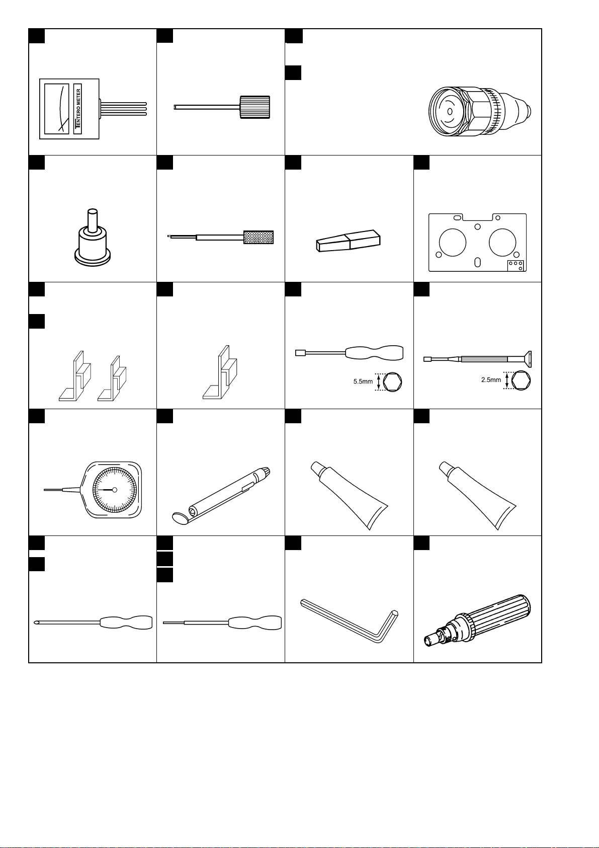
1. Servicing Fixtures & Tools
No. Part No. Fixture & Tool Name Remarks
1 VFK1145A Back Tension Meter (T2-M30-P)
2 VFK1149A Post Driver (2.5mm)
3 VFK71A Dial Torque Gauge (1.5cN-m) 150g
4 VFK1191A Dial Torque Gauge (0.45cN-m) 45g
5 VFK1152 Dial Torque Gauge Adapter
6 VFK0357 Eccentric Driver (1.5mm)
7 VFK1154 Post Height Fixture
8 VFK1586 Mech. Neutral Plate (L) For Post Height
9 VFK1155 REV Position Tool (Silver)
10 VFK1156 PLAY Position Tool (Black)
11 VFK1208 Neutral Position Tool (Black with Hole)
12 VFK1150 Nut Driver (5.5mm)
13 VFK1151 Nut Driver (2.5mm)
14 VFK1188A Dial Tension Gauge (30mN) 30g
15 VFK0948 Check Light
16 VFK0749 Froiral Grease For Plastic
17 MOR265 Morlytone Grease For Metallic
18 VFK1146 Phillips Driver (Fine) (00-75)
19 VFK1147 Phillips Driver (Fine) (0-100)
20 VFK1148 Hex. Driver (1.5mm)
21 VFK1178 Hex. Driver (0.89mm)
22 VFK1179 Hex. Driver (0.71mm)
23 VFK1190 Hex. Wrench
24 VFK1209A Torque Driver (4-30cN-m) 0.4-3kg
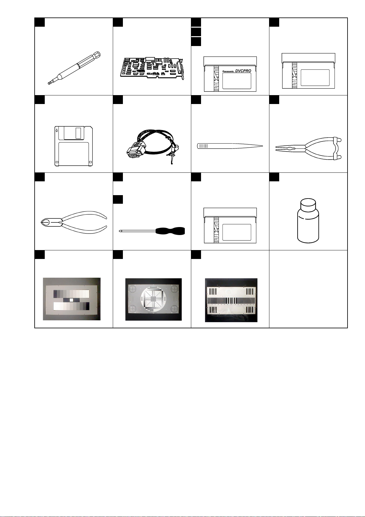
25 VFK1375 Hex. Bit (1.5mm)
26 VFK1300 AD Board (DAQ-12 Q uatec h)
27 VFM3580KL Alignment Tape (No.1) L-Cassette
28 VFM3581KL Alignment Tape (No.2) L-Cassette
29 VFM3582KL Alignment Tape (No.3) L-Cassette
30 AJ-CL12P Cleaning Tape SALES Route
31 VFK1481B LISTA Software
32 VFK1186 LISTA Cable
33 VFK0369 Tweezers
34 VFK0371 Radio Prier
35 VFK0372 Cutter Prier
36 VFK0337 Phillips Driver
37 VFK0338 Phillips Driver
38 VFK1369 Tape Sensor Adjustment Cassette
39 VFK0906 Lubrication Oil
40 VFK1642 Gray Scale Chart (Reflection type) 16:9
41 VFK1643 Resolution Chart (Reflection type) 16:9, For HD
42 VFK1644 Immega Cycle Chart (Transparency type) 16:9, For HD
INF-1
Page 4
1 VFK1145A (T2-M30-P)
Back Tension Meter
2 VFK1149A (2.5mm)
Post Driver
VFK71A (1.5cN-m)
3
3
(150g)
5 VFK1152
Dial Torque Gauge
Adapter
9 VFK1155
REV Position Tool (Silver)
10 VFK1156
PLAY Position Tool (Black)
6 VFK0357
Eccentric Driver
(1.5mm)
11 VFK1208
Neutral Position Tool
(Black with Hole)
VFK1191A (0.45cN-m)
4
(45g)
7 VFK1154
Post Height Fixture
12 VFK1150
Nut Driver (5.5mm)
Dial Torque Gauge
8 VFK1586
Mech. Neutral Plate (L)
13 VFK1151
Nut Driver (2.5mm)
VFK1188A 30mN14
Dial Tension Gauge
VFK1146
18
VFK1147
19
Phillips Driver (Fine)
VFK094815
Check Light
VFK1148 (1.5mm)20
VFK1178 (0.89mm)
21
22
VFK1179 (0.71mm)
Hex. Driver
VFK074916
Froiral Grease
(for Plastic)
VFK119023
Hex. Wrench
MOR26517
Morlytone Grease
(for Metallic)
VFK1209A 4-30cN-m
24
(0.4-3kg)
Torque Driver
INF-2
Page 5
VFK137525
Hex. Bit
VFK130026
AD Board
(DAQ-12 Quatech)
VFM3580KL27
VFM3581KL
28
VFM3582KL
29
Alignment Tape
AJ-CL12P
30
Cleaning Tape
VFK1481B31
LISTA Software
35 36
VFK0372
Cutter Prier
40 41 42
VFK1642
Gray Scale Chart
(16:9, Reflection Type)
VFK118632
LISTA Cable
VFK0337
Phillips Driver
37
VFK0338
Phillips Driver
VFK1643
Resolution Chart
(16:9,Reflection type)
33 34
38 39
VFK0369
Tweezers
VFK1369
Tape Sensor
Adjustment Cassette
VFK1644
Immega Chart (For HD,
Transpalency Type)
VFK0371
Radio Prier
VFK0906
Lubrication Oil
INF-3
Page 6
2. Alignment Tape
2-1. DVCPRO Alignment Tape
2-1-1. VFM3580KL
Time VIDEO PCM CUE
(min.) SIGN AL PORPOSE SIGNAL PORPOSE SIGNAL PO RPO SE
0:00
7:00
14:00
18:00
Color Bar
SMPTE (75%)
Color Bar
(100%)
H Sweep Frequency
Bowtie (500K) Y/C Timing
Confirmation of
the Composite
Video Level
Confirmation of
the Composite
Video Level
Characteristic
1KHz -20dB
1KHz 0VU Confirmation of
the CUE Level
Confirmation of
the Audio
Level
6KHz 0VU A/C Head
Azimuth
Adjustment
22:00
26:00
Pulse & Bar Y/C Timing 300, 500, 1K
2K, 4K, 6KHz
Area Marker Video Start
Timing
----- -----
Frequency
Characteristic
2-1-2. VFM3581KL
Time VIDEO PCM CUE
(min.) SIGNAL PORPO SE SIGNAL PORPOSE SIGNAL PO RPOSE
0:00
ITI Pattern Linearity
Adjustment --- --- --- ---
2-1-3. VFM3582KL
Time VIDEO PCM CUE
(min.) SIGNAL PORPOSE SIGNAL PORPOSE SIGNAL PORPOSE
0:00
Color Bar
(75%) (with
drop-out track)
X Value
Adjustment
--- ---
6KHz 10VU
X Value
Adjustment
INF-4
Page 7

3. List of Recommended Measuring and Instruments
MODEL No. (Example) NAME REMARKS
HD Monitor TV with SDI INPUT
Waveform Monitor · with SDI INPUT
LEADER LV5152DA Vector Scope · R,G,B/Y,Pb,Pr
Display Switching
Oscilloscope
Digital Volt Meter (D.V.M.)
Frequency Counter
Audio Analyzer
Spectrum Analyzer
Halogen Lump (X2) 500W 3200K
Lux Meter
Color Pyrometer
Special Light Box Spherical Type
INF-5
Page 8
4. Maintenance Schedule
Part Name
- Cleaning of the tape transport
1 Cylinder Ass’y
2 Pinch Arm Unit
3 Cleaning Arm Unit
4 S,T Reel Motor Unit
5 Thrust Screw Unit
6 S1 Loading Arm Unit
7 T1 Boat Unit
8 S5 Post Base Unit
9 Tension Arm Unit
10 S,T Cass. Brake Arm U.
Hours of Use (unit hours)
1,000H 2,000H 4,000H 6,000H 8,000H 10,000H 12,000H
"C": every 500 hours
RRRRRIM
R, Y, G R, Y, G R, Y, G R, Y, G R, Y, G R, Y, G IM
R, Y R, Y R, Y R, Y R, Y R, Y IM
RRIM
R R,L IM
RIM
RIM
RIM
RIM
RIM
11 Mode Switch Unit
12 A/C Head
13 Loading Motor (1) Arm Unit.
14 Pinch Solenoid
15 S,T Brake Solenoid
16 L Switch Base Unit
17 Cleaner Solenoid
18 Main Cam Gear
19 Mechanism Unit
20 Cassette Compartment Unit
RIM
Replacement of the mechanism chassis unit is recommended for the 12,000 h maintenance.
“C” : Perform cleaning.
“R” : Assembly subject to exchange.
“Y” : The timing of replacement with Cleaning Arm Unit,
either 1000 hours or 1 year as timing come earlier.
“G” : At the time of replacement, wipe off the old grease
and apply new grease. (Molytone Grease)
“L” : Lubrication is necessary.
“IM” : Included in the mechanical chassis unit
when the mechanical chassis unit is not replaced,
replacement as a single part is required.
<Note:>
The Hours of use indicates the cylinder rotation time
(DRUM RUN).
The maintenance execu tio n tim e shown in the ch art
is recommendation for standard maintenance
execution.
This is not the life of the various parts.
The life is influenced by temperature, humidity, dust,
etc.
IM
IM
IM
IM
IM
IM
IM
IM
IM
INF-6
Page 9
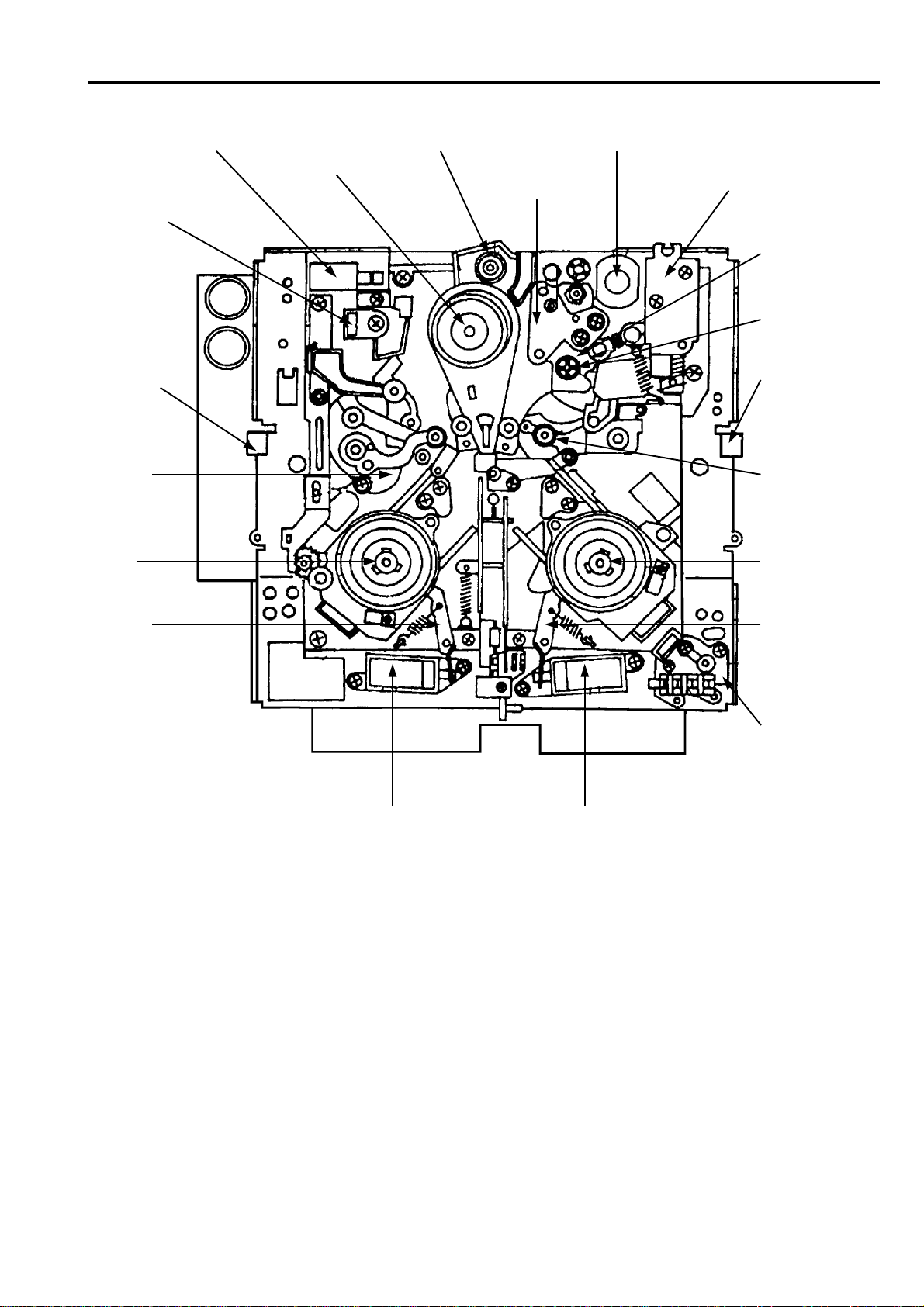
5. Layout of the Maintenance Parts & Sensors
Cleaning Solenoid
DEW Sensor
Tape End
Detect Sensor
Tension
Sensor
T Reel
Motor Unit
Cleaning Arm Unit
Cylinder Unit
Loading Motor
A/C Head
Pinch Solenoid
Capstan
Motor
Thrust Screw
Unit
Tape BEG/END
Detect Sensor
Pinch Arm
Unit
T Reel Motor
Unit
T Brake
Arm Unit
T Brake Arm
Unit
L Switch Base
Unit
T Brake SolenoidS Brake Solenoid
INF-7
Page 10
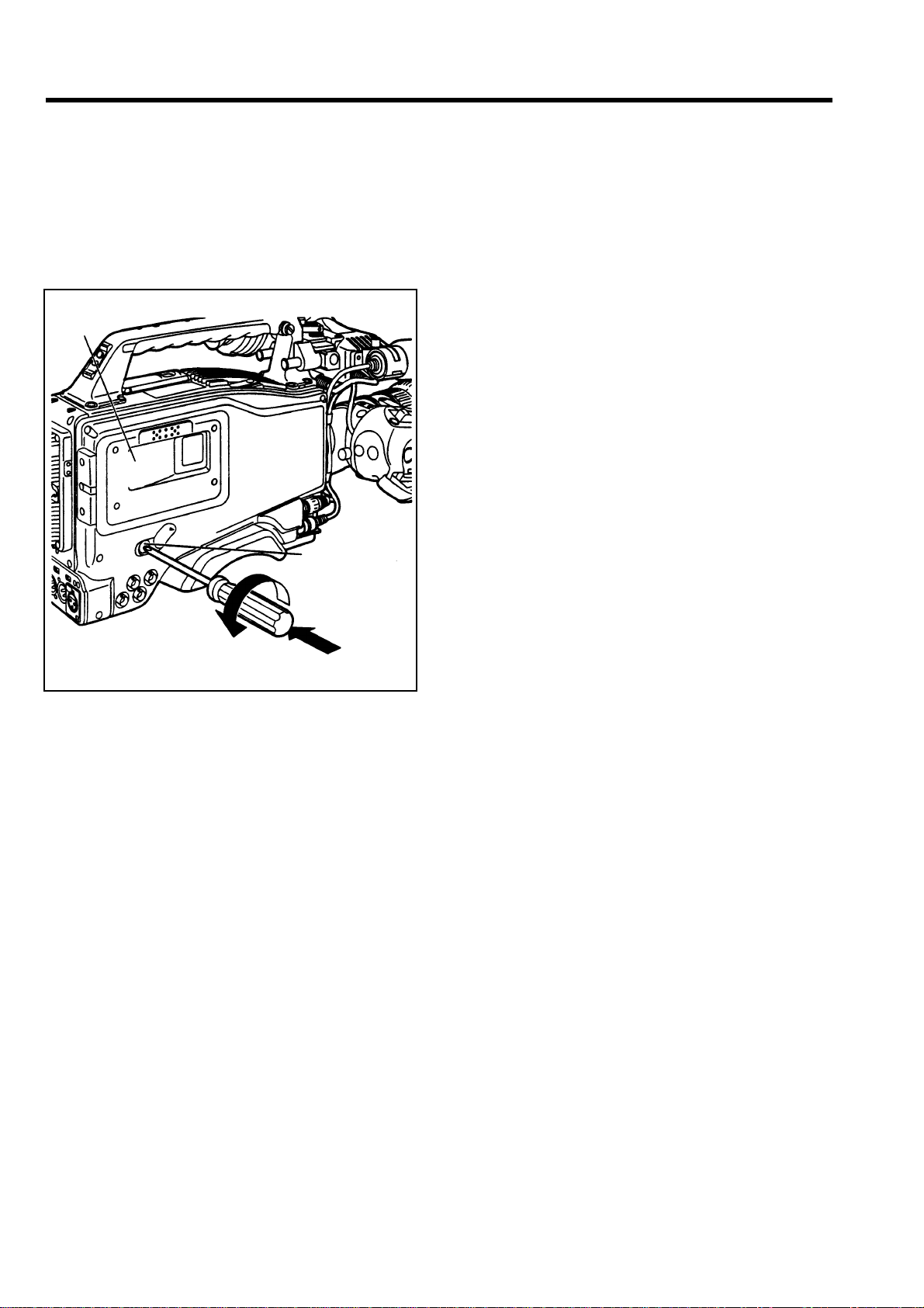
6. Emergency Eject
If the cassette cannot be ejected by pressing the
EJECT button, use a screwdriver or similar tool to
press and turn the EME RGENCY s crew. This enables
the cassette to be removed.
1. Turn the power OFF.
2. Remove the rubber cap where shown in the figure.
Insert a Phillips head screwdriver into the crossshaped part of the EMERGENCY screw (red).
CASSETTE
HOLDER
EMERGENCY
SCREW
4. Remove the cassette.
5. Return the rubber cap to its original position.
< Notes >
· Do not turn the EMERGENCY screw except in an
emergency.
· Do not turn the screw clockwise. Stop turning the
screw as soon as the tape is ejected. Otherwise, the
mechanism may be damaged.
· Af ter the tape is ejec ted, the cassette holder wil l not
be locked even when it is closed. Be sure to turn the
power off and turn it back on to reset the
mechanism’s operation, and then close the cassette
holder.
· A clicking sound will be heard while the
EMERGENCY screw is been turning: this sound is
made by the reel drive operation. Therefore it isn't
indication of a malfunction.
Turn the emergency screw by pushing it
3. While pushing in with the screwdriver, turn the
EMERGENCY screw counterclockwise until the
tape is ejected.
· This screw needs to be rotated through about 20
turns after the firs t turn until the unloading can
be started.
· This screw needs to be rotated through about 90
turns after the first turn until the tape is ejected.
INF-8
Page 11
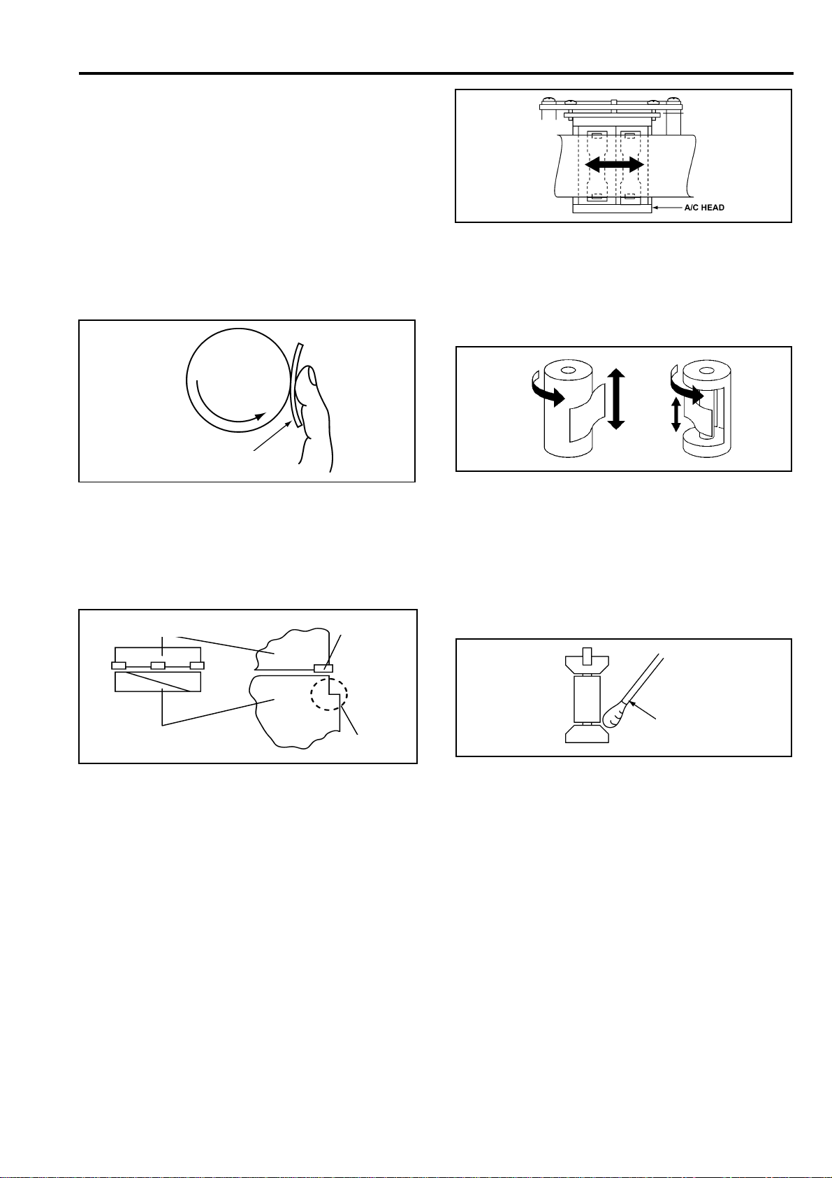
7. Cleaning Method
Note:
Turn the power OFF during cleaning.
Make sure the power is OFF before cleaning.
Use ethanol (more than 9 9% purit y) as c leaning
liquid.
7-1. Cylinder Head Cleaning
Method: (Daily)
Clean heads by applying even pressure and rotating
cylinder a few times. Never wipe in up and down
motion. Never touch a c ylinder by bare hand. At firs t
wipe with a cloth dippe d in cleaning liqu id. Then wipe
with dry cloth.
CYLINDER
Cleaning Cloth
7-2. Cylinder Lead Cleaning
Method: (Weekly)
Don’t touch a head chip. Clea n the drum lead with a
pick.
Upper Cylinder
Head
7-4. Pinch Roller and Capstan Shaft
Cleaning Method: (Weekly)
Wipe the Pinch Roller and Capstan with a cloth dipped
in cleaning liquid.
7-5. Post Cleaning Method: (Weekly)
Wind a cloth on a pick. Wipe each posts with that pick.
Wipe again with a dry cloth. For metal posts wipe with
a cloth dipped in cleaning liquid. Then wipe it again
with dry cloth.
Lower Cylinder
Lead
7-3. A/C Head Cleaning Method:
(Weekly)
Wipe the A/C head with a cloth dipped in cleaning
liquid. Wipe again with a dry cloth.
Cotton
Swab
Notes :
Use the clean cloth f or cleaning purpose. Do not use
any dirty cloth.
The cleaning cloth can be ordered as spare parts.
The part number is indicated as below.
CLEANING CLOTH : VZZ0095
INF-9
Page 12
8. Basic Setting Menu Operations
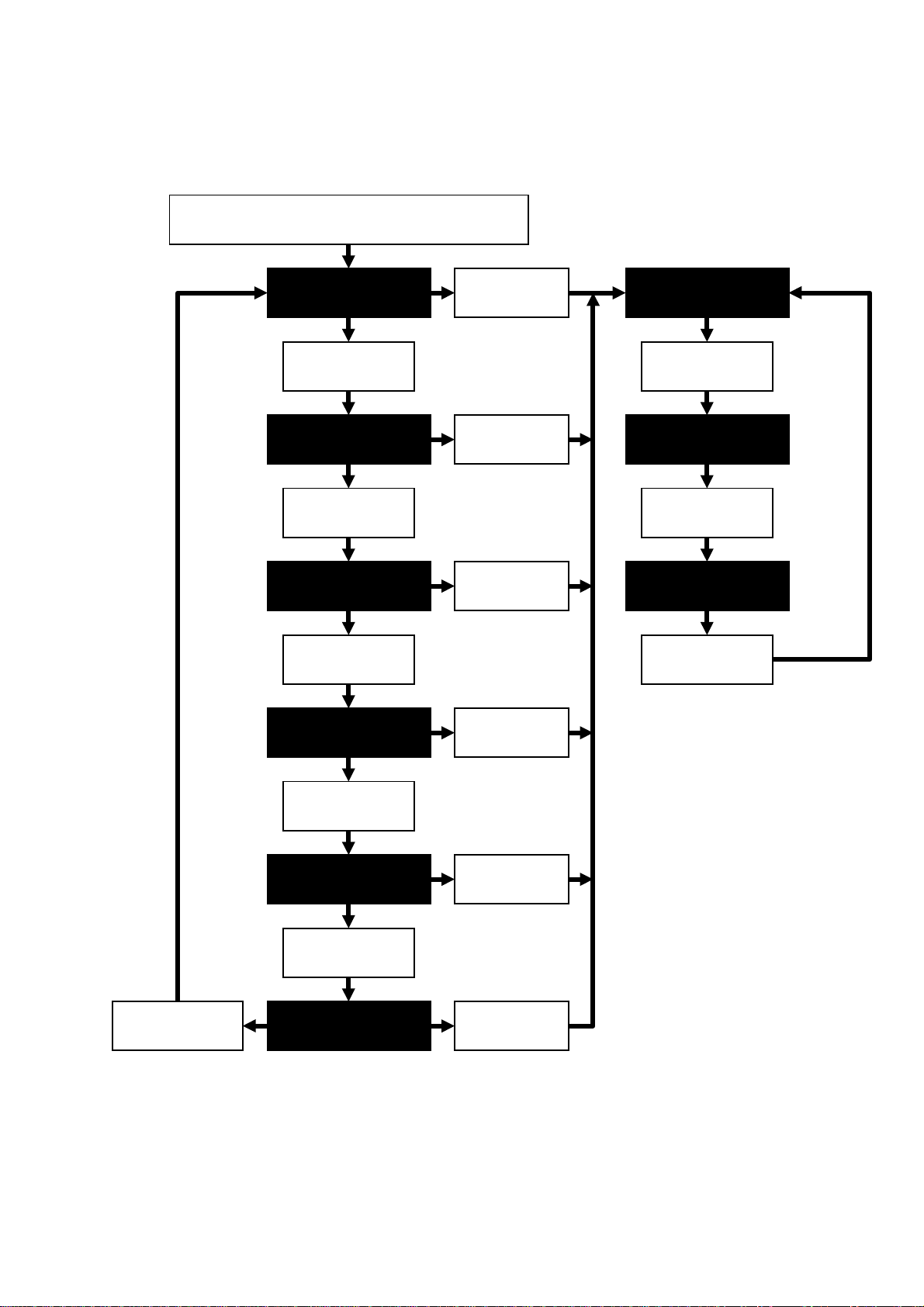
8-1. Service Menu Operation
1. Press the “SHIFT” and “+” buttons of the Tim e Code Operation Button simultaneously and press the MENU
button, and CAMERA unit’s SERVICE MENU screen is displayed.
2. When the MENU button is pressed again, the VTR unit’s SERVICE MENU screen is displayed.
Press the “SHIFT” & “+” buttons
simultaneously, and press the MENU button.
CAM MAIN MENU1
Press the JOG
dial button.
CAM MAIN MENU2
Press the JOG
dial button.
CAM MAIN MENU3
Press the JOG
dial button.
CAM MAIN MENU4
Press the
MENU button.
Press the
MENU button.
Press the
MENU button.
Press the
MENU button.
VTR MAIN MENU
Press the JOG
dial button.
VTR SERVICE MENU
Press the JOG
dial button.
Press the JOG
dial button.
CAM SERVICE MENU
Press the JOG
dial button.
Press the
MENU button.
INF-10
Page 13
8-2. Design Menu Operation
1. Press the “SHIFT ” and “RESET” buttons of the Time Code Operation Button simultaneo usly and press the
MENU button, and s witch to the CAMERA unit’s SERVICE MENU screen d isplay mode. At f irst “CAM MAIN
MENU1” screen is displa yed as shown below, but by pressing the JOG Dial button follo wing screen through
the “CAM DESIGN MENU” is displayed .
2. The SERVICE MENU and DESIGN MENU Can be displayed by pressing the JOG Dial button.
Press the “SHIFT” & “RESET” buttons
simultaneously, and press the MENU button.
CAM MAIN MENU1
Press the JOG
dial button.
CAM MAIN MENU2
Press the JOG
dial button.
CAM MAIN MENU3
Press the JOG
dial button.
CAM MAIN MENU4
Press the
MENU button.
Press the
MENU button.
Press the
MENU button.
Press the
MENU button.
VTR MAIN MENU
Press the JOG
dial button.
VTR SERVICE MENU
Press the JOG
dial button.
VTR DESIGN MENU
Press the JOG
dial button.
Press the JOG
dial button.
Press the JOG
dial button.
CAM SERVICE MENU
Press the JOG
dial button.
CAM DESIGN ME NU
Press the
MENU button.
Press the
MENU button.
INF-11
Page 14

8-3. Displaying Sub-Menus and
Setting Procedures
Setting procedures are same for both the USER
MENU and ENGINEER MENU.
2. Move the cursor to the desired SUB MENU item ,
and press the JOG Dial button.
The SUB MENU is now displayed.
(The cursor appears besidce the title part of the
SUB MENU.)
1. Turn the JOG Dial button while the USER MENU
screen or MAIN MENU screen is displayed.
The cursor moves to the SUB MENU item.
Example :
Turn the JOG
Dial button.
**** CAM MAIN MENU1 ****
ROP
MATRIX
COLOR CORRECTION1
COLOR CORRECTION2
LOW SETTING
MID SETTING
HIGH SETTING
ADITIONAL DTL1
ADITIONAL DTL2
SKIN TONE DTL
KNEE / LEVEL
GAMMA
CAMERASETTING
Example :
Press the JOG
Dial button.
**** CAM MAIN MENU1 ****
ROP
MATRIX
COLOR CORRECTION1
COLOR CORRECTION2
LOW SETTING
MID SETTING
HIGH SETTING
ADITIONAL DTL1
ADITIONAL DTL2
SKIN TONE DTL
KNEE / LEVEL
GAMMA
CAMERASETTING
< ROP >
MASTER PED : +008
MASTER DTL : +00
MASTER GAMMA : 0.45
R GAIN : +000
G GAIN : +000
B GAIN : +000
R PEDESTAL : +000
G PEDESTAL : +000
B PEDESTAL : +000
INF-12
Page 15

3. Turn the JOG Dial button to m ove the c ursor to the
desired item to be set, and press the JOG Dial
button.
The digit which value is to be set now flashes.
Example :
7. To move to the an other SUB MENU, turn the JO G
Dial button to move the cursor to the title part of the
SUB MENU, and press the JOG Dial button.
The USER MENU screen or MAIN MENU screen is
now displayed, so proceed with operation by
following the same steps.
Press the JOG
Dial button.
< ROP >
MASTER PED : +008
MASTER DTL : +00
MASTER GAMMA : 0.45
R GAIN : +000
G GAIN : +000
B GAIN : +000
R PEDESTAL : +000
G PEDESTAL : +000
B PEDESTAL : +000
4. Turn the JOG Dial button to change the setting.
5. When the desired settin g is shown, press the J OG
Dial button.
The setting is now entered.
6. When other items are to be set, turn the J OG Dial
button to move the cursor, and charge and enter
the settings by repeating steps 3 through 5.
Example :
Press the JOG
Dial button.
< ROP >
MASTER PED : +008
MASTER DTL : +00
MASTER GAMMA : 0.45
R GAIN : +000
G GAIN : +000
B GAIN : +000
R PEDESTAL : +000
G PEDESTAL : +000
B PEDESTAL : +000
8. Upon completion of the settings , press the MENU
button. Then the settings are now saved, exit the
settings menu mode, and return-to the normal
operation mode.
NOTE :
To exit the camera unit’s menu, press the MENU
button twice. W hen the M ENU butt on is pres s ed o nc e,
operation is transferred to the VTR unit’s menu.
INF-13
Page 16

8-4.Setting Menu Configurations
)
)
(
)
(
)
)
)
CAM SERVICE MENU
SERVICE ADJ R GAMMA
G GAMMA (SERV
B GAMMA (SERV
DEFECT COMPENSATION COMPENSATION
COMP ON GAIN
INTERLACE MODE
R CH
G CH
B CH
TRIPLE OFFSET
CURSOR BOX
READ DATA
WRITE DATA
ENTRY (AUTO
ENTRY (MANUAL
PICKUP LEVEL R
PICKUP LEVEL G
PICKUP LEVEL B
START
NG LIST NO
SELECT
ENTRY
CURSOR DISP
H CURSOR COARSE
H CURSOR FINE
V CURSOR COARSE
V CURSOR FINE
DEFECT SIZE
DEFECT COLOR
GAIN
OFFSET LEVEL A
OFFSET LEVEL B
ENTRY
CANCEL
SERV
EDIT / DELETE
WHITE SHADING
CAM SERVICE CARD R/W
INF-14
DEFECT NO.
DEFECT SIZE
DEFECT COLOR
GAIN
OFFSET LEVEL A
OFFSET LEVEL B
CHANGE
DELETE
ALL DATA CLEAR
DETECTION
R/W SEL
READ
WRITE
DIGITAL
Page 17

CAM DESIGN ME NU
)
)
(+)
)
)
)
VDRIVE 1
VDRIVE 2
PREPRO 1 G_WS_OFFSET
PREPRO 2
LSI REG SET 1
LSI REG SET 2
SHAD DA SET
KNEE APA SET
LSI C REG SET
AD READ TEST
DSP D/A SET
NO COMPENSATION
DESIGN MENU ALL INIT
VAH
VA13M
VA24M
VAL
VBL
LG
HPP
0D
P16V
R_PADC
G_PADC
B_PADC
DA RESET
R_GAIN
G_GAIN
B_GAIN
R_PED
G_PED
B_PED
M_PED
R_KNPT
G_KNPT
B_KNPT
A (0) or B (1
MEMORY SEL
ADR-H
ADR-L
DATA-H
DATA-L
THRESH LEVEL
SLOPE
FREQ.
GAIN
CORING LVL
DTL COMP
DTL COMP(–
DTL CLIP (+
DTL CLIP (–
KNEE SET
IRIS POS
ZOOM POS
FOCUS POS
LENS EXT
CC FILT
ND FILT
PEAKING
FRAME
ZEBRA
MARK SW
POSITION 1 R
B
POSITION 2 R
B
POSITION 3 R
B
POSITION 4 R
B
FACTORY MENU
R_0G
R_SUB
R_RESET DC
G_0G
G_SUB
G_RESET DC
B_0G
B_SUB
B_RESET DC
H1DC
H2DC
VSHIN
B_WS_OFFSET
R_WS_OFFSET
G_PRE_CLIP
B_PRE_CLIP
R_PRE_CLIP
G_PULCAN
B_PULCAN
R_PULCAN
A (0) or B (1
MEMORY SEL
ADR-H
ADR-L
DATA-H
DATA-L
WRITE
READ
BSHD_R
BSHD_G
BSHD_B
WSHD_G_SUB
WSHD_B
WSHD_G
WSHD_R
IRIS_C
ADR
DATA
WRITE
GAIN G
GAIN B
GAIN R
CPL G
CPL B
CPL R
INF-15
Page 18

VTR SERVICE MENU
VTR SERVICE 1/3
VTR SERVICE 2/3
CONCEAL
INNER ECC
OUTER ECC
VITERBI
ADJUST ADDRESS
ADJUST DATA
BER ADJ
BER SPEED
CW REC
AUTO EQ
RDS. REC ADJ
RDS TYPE
SERVO MODE
T TORQUE
S TORQUE
PG SHIFT 100
HSW_A_RIZE
HSW_A_FALL
HSW_C_RIZE
HSW_C_FALL
RPL GAIN 100
RPL LIN 100
CTL ADJ
X VALUE SET
X VALUE 100
TRK VAL 100
SERVO MODE
VTR SERVICE 3/3
VTR D/A DATA
VTR DESIGN MENU
VTR DESIGN MENU
TEST MODE
ERROR LOG
AUDIO PB SEL
AUDIO SAVE
AUDIO CH7/8
ADJUST ADDRESS
ADJUST DATA
MENU ALL INIT
DRUM RUNNING RESET
THREADING RESET
AGING MODE
FILE No.
LOG ALL CLEAR
ERROR CODE
SEQUENCE No.
DATE
TIME
OPERATION TIME
TAPE TOTAL
TAPE REMAIN
BATTERY ME TE R
OBJ/MODE
INF-16
Page 19

9. Service Menu Item Contents
< CAMERA Section >
9-1. CAM SERVICE MENU
ITEM
SERVICE ADJ R GAMMA (SERV) -30-+30 00 Adjustment for R GAMMA.
G GAMMA (SERV) -30-+30 00 Adjustment for G GAMMA.
B GAMMA (SERV) -30-+30 00 Adjustment for B GAMMA.
DEFECT COMPENSATION ON/OFF ON ON/OFF switching of blemish compensation.
COMPENSA- COMP ON GAIN -3dB-+30dB 12dB Specified gain of blemish compensation.
TION INTERLACE MODE PDMIX/FRAME PDMIX Select a way of correct operation.
R CH AVE/OFSET AVE Adjacent Picture Element Compensation/
G CH AVE/OFSET AVE Level Decrease
B CH AVE/OFSET AVE
TRIPLE OFFSET BAB/BBA BAB 3 adjacent picture elements decrease.
CURSOR BOX ON/OFF ON Indicate the box on the cursor.
READ DATA ON/OFF OFF Read the defect data.
WRITE DATA ON/OFF OFF Write the defect data.
ENTRY (AUTO) PICKUP LEVEL R 1-40 15 Detection Level of blemish.
PICKUP LEVEL G 1-40 10 Detection Level of blemish.
PICKUP LEVEL B 1-40 25 Detection Level of blemish.
START ON/OFF OFF ON/OFF Switching of Auto detection.
NG LIST NO 0-63 000 Display the NG List No.
SELECT OFF/A/B OFF Factory Use
ENTRY ON/OFF OFF Factory Use
CURSOR DISP ON/OFF ON Factory Use
ENTRY
(MANUAL)
EDIT/DELETE DEFECT NO. 0-255 0 Indicate the blemish data of specified number.
WHITE
SHADING
CAM SERVICE
CARD R/W
H CURSOR
COARSE
H CURSOR FINE 00-FF 80 Fine Adjustment for Horizontal Cursor Position
V CURSOR
COARSE
V CURSOR FINE 00-FF 80 Fine Adjustment for Vertical Cursor Position
DEFECT SIZE 1-3 1 Sequential Number of blemish.
DEFECT COLOR Y/R/G/B Y The color which has blemish.
GAIN ON/OFF ON ON/OFF switching of compensation followed gain.
OFFSET LEVEL A 0-255 100 Set the decrease value.
OFFSET LEVEL B 0-255 100 Set the decrease value.
ENTRY ON/OFF OFF ON/OFF switching of blem ish entry of above data.
CANCEL ON/OFF OFF Cancel for just before entry.
DEFECT SIZE 1-3 1 Sequential Number of blemish.
DEFECT COLOR Y/R/G/B Y The color which has blemish.
GAIN ON/OFF ON ON/OFF switching of compensation followed gain.
OFFSET LEVEL A 0-255 100 Set the decrease value.
OFFSET LEVEL B 0-255 100 Set the decrease value.
CHANGE ON/OFF OFF Entry the above data.
DELETE ON/OFF OFF Delete above entry data.
ALL DATA CLEAR ON/OFF OFF Delete all of entry data.
DETECTION
(DIGITAL)
R/W SEL DESIGN/SHADI
READ --- --- Read the DATA from the card.
WRITE --- --- Write the DATA to the ca rd.
SETTING
RANGE
00-08 03 Coarse Adjustment for Horizontal Cursor Position
00-04 02 Coarse Adjustment for Vertical Cursor Position
--- --- Execute the Digital white shading.
NG/DEFECT
INIT.
VALUE
--- Select the R/W DATA
MEANING of SETTING &
OUTLINE of FUNCTION
INF-17
Page 20

9-2. CAM DESIGN MENU
ITEM
VDRIVE 1 R_OG 00-FF FF OG voltage setting of R CCD.
R_SUB 00-FF 7E Sub voltage setting of R CCD.
R_RESET DC 00-FF 26 Reset DC voltage setting of R CCD.
G_OG 00-FF FF OG voltage setting of G CCD.
G_SUB 00-FF 7E Sub voltage setting of G CCD.
G_RESET DC 00-FF 26 Reset DC voltage setting of G CCD.
B_OG 00-FF FF OG voltage setting of B CCD.
B_SUB 00-FF 7E Sub voltage setting of B CCD.
B_RESET DC 00-FF 26 Reset DC voltage setting of B CCD.
H1DC 00-FF 80 H1 DC setting value of CCD.
H2DC 00-FF 80 H2 DC setting value of CCD.
VSHIN 00-FF FF Read voltage of CCD.
VDRIVE 2 VAH 00-FF 2E Read Out Pulse voltage of CCD (VH)
VA13M 00-FF 00 Transfer Pulse voltage of CCD (VM13)
VA24M 00-FF FF Transfer Pulse voltage of CCD (VM24)
VAL 00-FF 40 Transfer Pulse voltage of CCD (VAL)
VBL 00-FF 40 Transfer Pulse voltage of CCD (VBL)
LG 00-FF 6A Output Amp Voltage of CCD (LG)
HPP 00-FF FF H Transfer Pulse voltage of CCD (H)
0D 00-FF FF Output Amp Voltage of CCD (OG)
P16V 00-FF FF CCD Drive voltage (16V)
R_PADC 00-FF A8 Offset Adjustment for Rch Pre Amp
G_PADC 00-FF 98 Offset Adjustment for Gh Pre Amp
B_PADC 00-FF C7 Offset Adjustment for Bch Pre Amp
DA RESET OFF/ON OFF Initialize the all DA data.
PRE PROCESS1 G_WS_OFFSET ----- ----- G WHITE SHADING OFFSET Adjustment
B_WS_OFFSET ----- ----- B WHITE SHADING OFFSET Adjustment
R_WS_OFFSET ----- ----- R WHITE SHADING OFFSET Adjustment
G_PRE_CLIP ----- ----- Factory Use (Fixed at Factory)
B_PRE_CLIP ----- ----- Factory Use (Fixed at Factory)
R_PRE_CLIP ----- ----- Factory Use (Fixed at Factory)
G_PULCAN ----- ----- G PULSE CANCEL Adjustment
B_PULCAN ----- ----- B PULSE CANCEL Adjustment
R_PULCAN ----- ----- R PULSE CANCEL Adjustment
PRE PROCESS2 R_GAIN ----- -----
G_GAIN ----- ----B_GAIN ----- ----R_PED ----- ----G_PED ----- ----B_PED ----- ----M_PED ----- ----- Master Pedestal Value (For 0IRE Adjustment)
G_KNPT ----- ----- G Knee point value
B_KNPT ----- ----- B Knee point value
R_KNPT ----- ----- R Knee point value
SETTING
RANGE
INIT.
VALUE
AWB Adjustment Value
ABB Adjustment Value
MEANING of SETTING &
OUTLINE of FUNCTION
INF-18
Page 21

(CAM DESIGN MENU)
ITEM
LSI REG SET1 A (0) or B (1) ----- ----- Not used
MEMORY SEL ----- ----- Not used
ADR_H ----- ----ADR_L ----- ----DATA_H ----- ----DATA_L ----- ----WRITE ----- ----- STORE command of Adjustment data
READ ----- ----- READ command of Adjustment data
LSI REG SET2 A (0) or B (1) ----- ----- Not Used
MEMORY SEL ----- ----- Not Used
ADR_H ----- ----- Not Used
ADR_L ----- ----- Not Used
DATA_H ----- ----- Not Used
DATA_L ----- ----- Not Used
SHAD DA SET BSHD_R ----- -----
BSHD_G ----- ----BSHD_B ----- ----WSHD_G_SUB ----- ----WSHD_B ----- ----WSHD_G ----- ----WSHD_R ----- ----IRIS_C ----- -----
KNEE APA SET TRESH LEVEL ----- -----
SLOPE ----- ----FREQ ----- ----GAIN ----- ----CORING LVL ----- ----DTL-COMP (+) ----- ----DTL-COMP (–) ----- ----DTL-CLIP (+) ----- ----DTL-CLIP (–) ----- ----KNEE SET ----- -----
LSIC REGSET ADR ----- ----- Not Used
DATA ----- ----- Not Used
WRITE ----- ----- Not Used
AD READ TEST IRIS POS ----- ----- Lens iris position info rmation
ZOOM POS ----- ----- Lens zoom position information
FOCUS POS ----- ----- Lens focus position information
LENS EXT ----- ----- Lens extender position information
CC FILT ----- ----- CC Filter position information
ND FILT ----- ----- ND Filter position information
PEAKING ----- ----- Not Used
FRAME ----- ----- Not Used
ZEBRA ----- ----- Information of Zebra pattern on Viewfinder
MARK SW ----- ----- Not Used
SETTING
RANGE
INIT.
VALUE
MEANING of SETTING &
OUTLINE of FUNCTION
Data address of Flash memory (at CAM_SYS)
Data value of Flash memory (at CAM_SYS)
(To Flash memory)
(From Flash memory)
Factory Use only (Fixed at Factory)
Not Used
(ON or OFF Information)
INF-19
Page 22

(CAM DESIGN MENU)
ITEM
DSP D/A SET GAIN G ----- ----- G A/D converter input gain adjustment
GAIN B ----- ----- B A/D converter input gain adjustment
GAIN R ----- ----- R A/D converter input gain adjustment
CPL G ----- ----- G A/D converter input clamp level adjustment
CPL B ----- ----- B A/D converter input clamp level adjustment
CPL R ----- ----- R A/D converter input clamp level adjustment
ND POSITION1 R -127-+128 0 R GAIN Adjustment at ND FILTER POSITION 1.
COMPENSATION POSITION1 B -127-+128 0 B GAIN Adjustment at ND FILTER POSITION 1.
POSITION2 R -127-+128 0 R GAIN Adjustment at ND FILTER POSITION 2.
POSITION1 B -127-+128 0 B GAIN Adjustment at ND FILTER POSITION 2.
POSITION3 R -127-+128 0 R GAIN Adjustment at ND FILTER POSITION 3.
POSITION1 B -127-+128 0 B GAIN Adjustment at ND FILTER POSITION 3.
POSITION4 R -127-+128 0 R GAIN Adjustment at ND FILTER POSITION 4.
POSITION1 B -127-+128 0 B GAIN Adjustment at ND FILTER POSITION 4.
SETTING
RANGE
INIT.
VALUE
MEANING of SETTING &
OUTLINE of FUNCTION
< VTR Section >
9-3. VTR SERVICE 1/3
ITEM
CONCEAL ON/OFF ON NG NG CONCEAL setting
INNER ECC ON/OFF ON NG NG INNER ECC setting
OUTER ECC ON/OFF ON NG NG OUTER ECC setting
VITERBI ON/OFF ON NG NG VITERBI setting
ADJUST ADDRESS 01-24h 01 NG NG
ADJUST DATA 00-FFh ----- OK NG
BER ADJ OFF/
BER SPEED SLOW/FAST SLOW NG NG Speed setting of Error rate display
CW REC OFF/
AUTO EQ ON/OFF ON NG NG AUTO RF,EQ setting
RDS. REC ADJ OFF/
RDS. TYPE OFF/BOTH/
SERVO MODE ATF/CTL ATF NG NG Servo mode setting
SETTING
RANGE
L1L3/R1R3/
L2L4/R2R4
20M/5M
L1/L3/
R1/R3/
L2/L4/
R2/R4
REC/SPLAY
INIT.
VALUE
OFF NG NG
OFF NG NG
OFF NG NG
BOTH OK NG
Backup
Backup
(INH.)
MEANING of SETTING &
OUTLINE of FUNCTION
EVR adjustment for VTR part
Error rate display mode setting
Frequency setting for RF,EQ adjustment
Head select for RDS (REC SIGNAL DETECTIO N
SYSTEM) adjustment
RDS setting
INF-20
Page 23

9-4. VTR SERVICE 2/3
ITEM
T TORQUE -128-+127 0 OK NG Take-up reel torque adjustment
S TORQUE -128-+127 0 OK NG Supply reel torque adjustment
PG SHIFT 100 ----- ----- PG shifter adjustment
HSW_A_RIZE 0-4095 0x500 OK NG Rising edge
HSW_A_FALL 0-4095 0x500 OK NG Falling edge
HSW_C_RIZE 0-4095 0x500 OK NG Rising edge
HSW_C_FALL 0-4095 0x500 OK NG Falling edge
RPL GAIN 100 -128-+127 64 OK NG RPL head ATF pre-filter gain adjustment
RPL LIN 100 OFF/ON OFF NG NG RPL head LISTA linearity adjustment
CTL ADJ OFF/ON OFF NG NG CTL Adjust mode setting
X VALUE SET OFF/ON OFF NG NG X value adjustment
X VALUE 100 -128-+127 0 OK NG Fine adjustment for X value
TRK VAL 100 -128-+127 0 NG NG CTL tracking offset setting
SERVO MODE ATF/CTL ATF NG NG Servo mode setting
SETTING
RANGE
INIT.
VALUE
Backup
Backup
(INH.)
MEANING of SETTING &
OUTLINE of FUNCTION
9-5. VTR SERVICE 3/3
ITEM
AUDIO PB SEL CH1,2/
AUDIO SAVE ACTIVE/OFF
AUDIO CH7/8 EE FORCH/
SETTING
RANGE
CH3,4/
CH5,6/
CH7,8
EE,PB
INIT.
VALUE
CH1,2 NG NG
ACTIV
E
EE,PB OK OK
Backup
NG NG
Backup
(INH.)
MEANING of SETTING &
OUTLINE of FUNCTION
9-6. VTR DESIGN MENU
ITEM SETTING RANGE INIT. VALUE
MENU ALL INIT ----- ----DRUM RUNNING
RESET
THREADING
RESET
----- -----
----- -----
INF-21
MEANING of SETTING &
OUTLINE of FUNCTION
Page 24

9-7. TEST MODE
ITEM SETTING RANGE INIT. VALUE
AGING MODE OFF/ON OFF
ON : TEST MODE (VTR RUNNING TEST)
(Repeat 5 minutes REC and 1 minute STAND-BY)
MEANING of SETTING &
OUTLINE of FUNCTION
9-8. ERROR LOG
ITEM SETTING RANGE INIT. VALUE
FILE No. 1-5 1 Be able to select 1 through 5.
1 : Old Error Data ® 4 : Recent Error Data
5 : First Error
(Cannot delete until execute LOG ALL CLEAR)
LOG ALL CLEAR OFF/ON OFF ON : All Clear
Finally, turn OFF or POWER OFF.
ERROR CODE E-00
SEQUENCE NO 00
DATE 00/01/01
TIME 12 : 34 : 56
OPERATION
TIME
TAPE TOTAL 120min
TAPE REMAIN 90min
BAT T E RY METER 1-F Example : “a-F”
OBJ/MODE 00 00 00 : 00 : 00 00 00 12 : 34 : 56 Indicate the time when OBJ/MODE occurred.
00 00 00 : 00 : 00 00 00 12 : 34 : 56 Upper - occurred lately
00 00 00 : 00 : 00 00 00 12 : 34 : 56 ¯
00 00 00 : 00 : 00 00 00 12 : 34 : 56 Lower - occurred formerly
00 00 00 : 00 : 00 00 00 12 : 34 : 56
000000Hr
“a” indicates the meter number.
”-F” indicates the blink (flash).
MEANING of SETTING &
OUTLINE of FUNCTION
¯
INF-22
Page 25

10. Adjustment after Optical Unit Replacement
When replace the Optical Unit (PRE AMP, CCD
PULSE, DRIVE Board included), execute the
adjustment as following procedures.
In this case, do not ne ed to execute the Optical Unit
Adjustment on the “Section 5 : Electrical Adjustment”.
10-1. Input the Adjustment Data
1. Set the Shading Correction to “OFF” as follows.
*** CAM MAIN MENU 4 ***
< BLACK SHADING >
® CORRECT (DIG) : “ON“ ® “OFF”
< WHITE SHADING >
® CORRECT : “ON“ ® “OFF”
2. Input the adjustm ent data following th e Adjustm ent
Data Sheet which is included with optical unit.
< Items mentioned on the Adjustment Data Sheet >
(8 items)
*** CAM DE SIGN MENU ***
< VDRIVE 1 >
® R-SUB ® R-RESET DC
® G-SUB ® G-RESET DC
® B-SUB ® B-RESET DC
10-2. Electrical Adjustment
Execute the Confir m ation and Adjus tm ent as f ollowing
items. (Refer to “Section 5 : Electrical Adjustment”)
1. 0IRE PED Adjustment
2. R,G,B PRE AMP DC Confirmation
3. R,G,B PULCAN Adjustment
4. R,G,B PREPRO Level Confirmation
5. R,G,B PED TRACK Adjustment
6. Modulation Confirmation
7. R,G,B W/S (WHITE SHADING) OFFSET Adj.
8. Digital W/S (WHITE SHADING) Adjustment
9. Digital D/S (DARK SHADING) Adjustment
10. FLARE Adjustment
11. R,B GAMMA Adjustment
*** CAM DE SIGN MENU ***
< VDRIVE 2 >
® H1-DC
® VSHIN
3. Input or execute the following setting by menu.
(Memory of Setting Value)
*** CAM DE SIGN MENU ***
< LSI REG SET 1 >
® ADR_H : “FF” (input)
® ADR_L : “01” (input)
® WRITE : “OFF” ® “ON” (execute)
INF-23
Page 26

11.DIAG-MENU Display
11-1-1. Version Display Operation Procedure (CAMERA Part)
1. Open the “ENG menu” (Press “MENU Button” more than 3 second.)
2. Open “
3. Select “DIAGNOSTIC” page (Turn and Press JOG Dial), then the Software version for each item can be
comfirmed.
11-1-2. How to read the Version Display
CAM MAIN MENU 4
< DIAGNOSTIC >
®
CAMSOFT (IN) Ver T1.00-01-1.00
CAMSOFT (OUT) Ver T1.00-01-1.00
GAMMA GAIN Ver T1.00-01-1.00
GAMMA RAM Ver T1.00-01-1.00
KNEE Ver T1.00-01-1.00
ALC Ver T1.00-01-1.00
PLD Ver T1.00-01-1.00
” page (Press JOG Dial)
Flash memory (Included IC1) Software Version
Flash Memory (IC2) Software Versi on
GAMMA Table Software Version
Black GAMMA Table Software Version
KNEE Table software Version
ALC Software Version
PLD Software Version
Ver T1.00-01-1.00
T
: 59.94Hz
E
: 59.94Hz/50Hz
P
: 50Hz
Software Version
11-2-1. Version Display Operation and Hour Meter Display (VTR Part)
1. Open the “ENG menu” (Press “MENU Button” more than 3 second.)
2. Press “MENU Button” again to open the “VTR MAIN MENU”.
3. Sel ect “DIAGNOSTICS” page (Turn and Pres s JOG Dial), then the Software version for each item can be
comfirmed.
< DIAGNOSTIC >
®
OPERATION 99999X10h
DRUM RUNNING 99999X10h
THREADING 99999
VTR SYSCON n1.00-01-1.00
SERVO n1.00
MECHACON n1.00
FRONT n1.00-01-1.00
Operation Hour (: 10HOUR x)
Cylinder Moter running Hour (: 10HOUR x)
Loading, Unloading Times
VTR SYSCON FLASH memory Software Version
SERVO ROM
MECHANISM CONTROL ROM
AUDIO LCD ROM
11-2-2. How to read the Version Display
n1.00-01-1.00
n
p
Brank : NTSC/PAL
:NTSC
:PAL
Software Version
INF-24
Page 27

11-2-3. How to Reset Hour Meter
1. Open the “Design Menu” and then press “MENU Button”.
2. Open “
3. Select “VTR DESIGN MENU” item. (Turn & press JOG Dial)
4. After the following figure is displayed, move “®” to the item to reset.
VTR DESIGN MENU
**** VTR DESIGN MENU ****
VTR DESIGN MENU
®
TEST MDOE
ERROR LOG
VM PLD V0.00
VTR SYSCON V18388a
<VTR DESIGN MENU>
MENU ALL INIT
®DRUM RUNNING RESET
THREADING RESET
” page. (Press JOG Dial)
00.06.13
INF-25
Page 28

12. Error Rate Display and Confirmation Method
12-1. Error Rate Display Method
1. Open the “VTR SERVICE MENU”.
2. Select “
3. Confirm “
4. Select "
BER ADJ item :
5. The Error rate will be displayed in the Audio meter on the Audio LCD panel.
VTR SERVICE 1/3
BER SPEED
BER ADJ
” setting is “
" by rotating JOG Dial and Select R/P head to be confirmed.
OFF / L1L3 / R1R3 / L2L4 / R2R4 (exept OFF)
” page.(Turn & press JOG Dial)
SLOW
”.
AUDIO LCD METER
- 0 -
- 10 -
- 20 -
- 30 -
- 40 -
-
-
¥¥¥¥
CH1 CH2
L1
R1
L2
R2
dB
L3
R4
L3
R4
Error rate Spec. ”A”
INF-26
Page 29

13. Internal Switch Setting Method
The switche settings on each circuit board are shown below.
“Factory use only” switches must be set to the “Factory setting”.
BOARD Ref. No. SW
AUDIO LCD 1-7 ON (FIXED) Factory use only
SW40001
SW40002
1-5 OFF(FIXED) Factory use only
SW47001
SW41001 - -60 REAR CH1 MIC input level setting (-60dBu / -40dBu)
SW42001 - -60 REAR CH2 MIC input level setting (-60dBu / -40dBu)
SW41002 - -40 FRONT CH1 MIC input level setting (-50dBu / -40dBu)
SW42002 - -40 FRONT CH2 MIC input level setting (-50dBu / -40dBu)
VTR SYSCON 1 OFF (FIXED) Not used
SW500
3-4 OFF (FIXED) Factory use only
SW501
FACTORY
SETTING
8 ON Not used
6 OFF ON : ENG SEQURITY ON
1 ON Factory use only
2 OFF Factory use only
3 ON Factory use only
4 OFF Factory use only
2 OFF EE-ROM write protect (allow is ON side)
1 OFF (FIXED) Not used
EE-PROM initia li ze
<ROM initialization procedur e >
1. Turn Off the unit
2OFF
2. Switch SW201-2 and SW 500-2 to ON ® Turn On the
unit.
3. After 5 second, initialization is completed ® Turn Off the
unit.
3 OFF (FIXED) Factory use only
4 OFF (FIXED) Factory use only
FEATURE
AUDIO LCD board
SW40001
SW40002
SW7001
SW2001
SW1001
SW2002 SW1002
VTR SYSCON board
SW501
SW500
INF-27
Page 30

14. Circuit board layout
E5. CAMERA MOTHER P.C.BOARD
E7-2. MEMORY P.C.BOARD
E7-1. DSP MAIN P.C.BOARD
E2. TG P.C.BOAR D
E1. PRE AMP P.C.BOARD
E25. CCD SENSOR P.C.BOARD
E3. DRIVE P.C.BOARD
E34. SD CARD P.C.BOARD
E28. FRONT TOGGLE P.C.BOARD
E12. SERVO P.C.BOARD
E9. VTR MOTHER P.C.BOARD
E11. SERVO FLEX P.C.BOARD
E13. HEAD BUFF P.C.BOARD
E32. OPERAT E P.C.BOARD
E38. BACK TALLY P.C.BOARD
E39. SIDE BNC P.C.BOARD
E30. REAR SW P.C.BOARD
E31. CUE P.C.BOARD
E18. REAR JACK P.C.BOARD
E40. SDI BNC P.C.BOARD
E26. HEAD PHONE P.C.BOARD
E27. EXT DC P.C.BOARD
E15. POWER MAIN P.C.BOARD
E16. POWER SUB P.C.BOARD
E17. AUDIO LCD P.C.BOARD
E22. SYNCHRO SW P.C.BOARD
E29. JOG MENU P.C.BOARD
E33. FRONT MIC P.C.BOARD
E4. PRE PROCESS P.C.BOARD
E6. CAMERA SYSCON P.C.BOARD
E8. VIDEO OUT P.C.BOARD
E21. MONITOR SW P.C.BOARD
E23. USER SW P.C.BOARD
E20. TOGGLE SW P.C.BOARD
E24. MENU SW P.C.BOARD
E19. POWER SW P.C.BOARD
E14. RF EQ P.C.BOARD
E36. VIDEO MAIN P.C.BOARD
E10. VTR SYSCON P.C.BOARD
E37. HD SDI TX P.C.BOARD
INF-28
Page 31

15. PLD Version Upgrade Method
The AJ-HDC27A has two Programmable Logic Devices (PLD) b y ALTERA Cor poration on CAM_S YS P.C. Board
(IC100) and VM (Video Main) P.C.Board (IC321). See following procedures for details.
15-1. Preparation
Equipment Remarks
CPLD WRITER
D-sub 25pin-25pin Cable Straight type (male - female), Length must be within 1meter
Upgrade tool software
Version Upgrade data
Personal Computer With WINDOWS 95Ò or 98Ò
15-2. Connection
IC100 (CAM_SYS P.C.Board)
1. Connect D-sub cable between connector CN201 on VFK1590 and PC.
2. Connect CPLD Writer cable between connector P201 on VFK1590 and connector P100 on CAM_SYS
P.C.Board. (Refer to Figure 15-1)
3. Turn on the power of camcorder and then boot-up PC.
VFK1590 (Interface board)
VFK1590P2 (Connection cab le: Su pp lie d with VFK 1590)
MAX+plus II Software : www.altera.com/pub/software/asap2.exe
Download from above URL and then install to any directory of PC.
IC100 : TDF format file (Include it in “vsi xxxx”)
IC321 : POF format file (Include it in “vsi xxxx”)
Notice: Flash memory software versions on each P.C.Board sometimes need to be
upgraded together with PLD version up. Before PLD version up, confirm the
instruction of each vsi file.
IC321 (VM P.C.Board)
1. Connect D-sub cable between connector CN201 on VFK1590 and PC.
2. Connect CPLD Writer c able (VFK1590P 2) betwee n connector P20 1 on VFK15 90 and co nnector P3 20 on VM
P.C.Board. (Refer to Figure 15-1)
3. Turn on the power of camcorder and then boot-up PC.
D-SUB 25 pins
Cable
PC
Connector P201
VFK1590P2
Connector
VFK1590
CN201
P100
P320
Figure 15-1 Connection
INF-29
Page 32

15-3. Version-up Procedures
1. Boot up MAX+plus II 9.6 programmer only.
2. On main window, select tab “MAX-plus II” and then ”Programmer”.
3. On main window (Programmer window is displayed), select tab “Option” and then “Hardware setup”.
4. On Hardware Setup dialog, set Hardware Type to “ByteBlaster (MV)”.
5. On main window, select tab “File”, “Project” and then “Name”.
6. On Dialog of Project Name, select the “TDF file (IC100)” or “POF file (IC321)” and then Click “OK button”.
INF-30
Page 33

7. Click “Program button” on Programmer dialog.
8. When Progress bar r eaches at point of “100”, the mes sage “Programm ing completed” appears, th en PLD
version upgrade is completed.
9. Click “OK Button” on “Programming complete” message dialog.
Progress bar
10. Turn the power of camcorder OFF and ON.
11. Confirm the current version of PLD on DIAGNOSTIC page (IC100: CA M SYS Board) and VTR DESIGN
page (IC321: VM Board). (See page of INF-10 through 16 in this service manual for how to open each menu
screen.)
<DIAGNOSTIC>
®
CAMSOFT (IN)
CAMSOFT (OUT)
GAMMA GAIN
GAMMA RAM
KNEE
PLD
Ver T1.xx-01-1.xx
Ver T1.xx-01-1.xx
Ver T1.xx-01-1.xx
Ver T1.xx-01-1.xx
Ver T1.xx-01-1.xx
Ver T1.xx-01-1.xx
**** VTR DESIGN MENU****
®
DESIGN MENU
TEST MODE
ERROR LOG
VM PLD
VTR SYSCON
V x.xx
V1.8126a
00.00.00
DIAGNOSTIC page VTR DESIGN page
* MAX+PLUS is registered trademark of Altera Corporation in the Unit ed Stat es and/or other countries.
* Windows95 and Windows98 are either registered trademarks of Microsoft corporation in the United States and/or other countries.
INF-31
Page 34

16. Flash Memory Version Upgrade Method
The AJ-HDC27A has Flash memories IC202 on CAM_SYS P.C.Board, IP100 on VTR_SYS P.C.Board and IC100
on ERVO P.C.Board. Version upgrade procedures for each Memory is shown below.
IC 202
SW1
(Component side) (Solder side)
CAM_SYS P.C.B
IC 100
SERVO P.C.B (Component side)
P2 Connector
IP 100
P6100
Connector
VTR_SYS P.C.B (Component side)
16-1. Preparation
16-1-1. Equipment
Name Remarks
Flash memory versionup tool
RS-232C Cable 9pins – 9pins, Cross type, D-SUB
Version upgrade Software
Version-up Data
Personal Computer With MS-DOS, Windows95 or Windows 98
* MS-DOS, Windows95 and Windows98 are either registered trademarks of Micros oft corporation in the United States and/or other countri es.
VFK1304 (Connection Board and Flat cable)
CAM_SYS P.C.B
VTR_SYS P.C.B
SERVO P.C.B
VVVSI File
: XXXXX.BAT (come with each Version-up data)
: VFK1248E (For WINDOWS 95Ò or 98Ò type)
: VFK1503
INF-32
Page 35

16-1-2. Setting of VFK1304A
Before executing version upgrade, Set “Cable type setting” and ”W riting function setting” on VFK1304A as
shown below. If any settings are wrong, it can not communicate to PC.
Writing function setting (SW1)
SW1 SW2 SW3 SW4
ON ON OFF OFF
ON ON OFF OFF
ON OFF OFF OFF
(R1, R2, R3, R4)
ON
1
2
3
4
ON
1
2
3
4
1
2
3
4
R1 = OPEN
R2 = OPEN
R3 = SHORT
R4 = SHORT
ON
SW1
VFK1304A
Figure 16-1
R3
R1
R4
Board
CAM_SYS
VTR_SYS
R2
SERVO
16-2. Version Upgr ade for CAM_SYS P.C.Board
16-2-1. Getting the user data
1. Get the User data with Multimedia Card (See Op erating Instructions pa ge numbers 59 – 63 for Details of
Getting the User data.)
Cable type
setting
16-2-2. Connection
1. Connect RS-232C Cable between connector P2 on VFK1304A and COM 1 port on PC. (Refer to Figure.
16-2)
2. Connect Flat cable bet ween connec tor P1 on VFK130 4A and conn ector P2 on CAM_ SYS P.C.Boar d, and
then set SW1 on VFK1304A according to Figure. 16-1.
3. Set “SW201” on CAM_SYS P.C.Board to “ON” (Up-side at condition of slot into the unit)
4. Turn on the power of the unit and then boot-up PC (MS-DOS mode).
D-SUB 9pins
PC
cable
VFK1304A
Camcorder
SW201
CAM_SYS P.C.B
Figure 16-2
ON
INF-33
Page 36

16-2-3. Software Version Upgrading
1. Copy all files in “Version up data (vvvsi file)” to arbitrary directory. (Please make a directory)
2. Type “xxxxx.bat” and then hit RETURN key.
3. Data transfer will be started from PC to camcorder. Data transferring scheme is shown below.
Scheme of Flash memory writing
ERASE : Data all clear on Flash memory
WIRTE : Data writing to Flash memory
VERIFY : Verifying data between wrote data
and original data
4. When progress bars reaches at 100% position, data
transfer is completed.
5. Set “SW201” to OFF side.
6. Turn OFF®ON the power of camcorder and then
confirm software’s version.
NOTE:
Each software version is indicated on <DIAGNOSTIC> menu screen (CAM MAIN MENU4 page).
16-2-4. Restoring User Data
1. Restore the User data with Multimedia card. (See Operating Instructions page numbers 59 – 63 for Details
of restoring the User data.)
16-2-5. Trouble Shooting
Symptoms
Cause
Check point
Error message “ERROR: RS232C: Line Open Error” is ap peared and then
data transferring is interrupte d.
Could not communicate between PC and camcorder.
* Did you use RS-232C cable as designated? (9pins-9pins, Cross)
* Did you set SW201 on CAM_SYS P.C.B to “ON” side?
* Did you turn on the power of camcorder?
INF-34
Page 37

16-3. Version Upgrade for VTR_SYS P.C.Board
16-3-1. Connection
1. Connect RS-232C Cable between connector P2 on VFK1304A and COM1 port on PC. (Refer to Figure. 16-
2.)
2. Connect Flat cable between connector P1 on VFK1304A and conn ector P6100 on VTR_SYS P.C.Board,
and then set SW1 on VFK1304A according to Figure. 16-1.
3. Turn on the power of the unit and then boot-up PC (WINDOWS mode).
16-3-2. Software Version Upgrading
1. Copy all files of VFK1248E to arbitrary directory.
2. Double-click the program file icon
3. When this Software is started, a dialog will be opened as shown below.
“VSI2312E.EXE”
.
4. Set parameters on
Microcomputer select............................. M32160F4UFP
Writing data ............................................ File data
Enter new version-up data name (XXXX.mot) with full path. You can also use “Browse…” button on
the “Setup panel” to select the file name and location of the new version-up data.
Target machine ID check ....................... Off
Port......................................................... Set the port which RS-232C Cable is connected to PC.
Baud Rate .............................................. 115200
Stop Bits................................................. 1Bit
Byte Size ................................................ 8Bits
Parity ...................................................... None
“Setup Panel”
window.
INF-35
Page 38

5. When settings on the “Setup panel” is completed, click “OK(O)” button. “VSI212E Main panel” will be
opened as shown below.
6. Click “Start (S)” button on the “Mai n pa ne l” windo w, (C lic k “Exit” button to quit, C lic k “Setup (Z) to RET URN
to Setup panel”)
7. After erasing data of the Flash memory, New version-up data will be written to the Flash memory. While
processing, progress status can be confirmed by means of “Process” indicator. If the Indicator doesn’t
advance for some reason, click “Emergency stop (C)” button and then confirm settings.
8. When Process bar reaches at 100% position and “Waiting to start or Completed” indicator is marked,
Version-up is completed, then click “Exit (X)” button.
9. Turn off the power of DC po wer supply and th en set the power SW of camcorder to off. ( In this situation,
Power SW should not work.)
10. Disconnect VFK1304A and then turn on the power of camcorder.
INF-36
Page 39

16-4. Ver sion Upgr ading for SERVO P.C.Board
16-4-1. Connection
1. Connect RS-232C Cable between connector P2 on VFK1304A and COM1 port on PC. (Refer to Figure. 16-
2.)
2. Connect Flat cable between connector P1 on VFK1304A and connector P9811 on VTR MOTHER
P.C.Board, and then set SW1 on VFK1304A according to Figure. 16-1.
P9811
Figure 16-3 Operation side of the Unit
3. Turn on the power of camcorder and then boot up PC (MS-DOS mode).
4. Copy all files of version-up data and SERVO Version upgrade software (VFK1503) to the same directory.
SERVO Version upgrade software (VFK1503) “fw103u.exe”
SERVO Version upgrade data “vsiXXXX.obf”
“vsiXXXX.bat”
“vsiXXXX.ex”
5. Type “vsixxxx.bat” and then hit RETURN key.
6. Type “Y” and then hit RETURN key after display message “DO YOU CONTINUE? Y / N>”.
7. Data transfer will be started.
8. After data transfer is finished, turn off the power of the Unit.
9. Disconnect VFK1304A.
10. Turn on the power of camcorder and then confirm software version.
* Windows95, Windows98 and MS-DOS are either registered trademarks of Microsoft corporation in the United States and/or other countries.
INF-37
Page 40

17. Blemish Compensation Method
Features
a ) Possible to compensate each color signal individually (R, G and B). (Total amount : 256 points)
b ) It is possible to compensate blemish without extra equipment (PC, Service fixtures etc.).
Automatic blemish compensation function
c )
17-1. Preparation
1. Need about 2-hours aging before start an adjustment.
2. Set WHITE BAL SW, CC and ND filter wheels as shown below.
WHITE BAL SW : PRST
CC FILTER : Position “B”
ND FILTER : Position No. “1”
3. Close LENS Iris and then execute “A BB” b y the front switc h.
17-2. Connection
T o facilitat e b lemish compensation’s work, connect the cam c order and the HD T V- monitor through HD SDI output.
(With 75-ohm termination.)
. Also it is (possible to manual compensate too.)
HD-SDI
Panasonic
HD TV-monitor
INF-38
Page 41

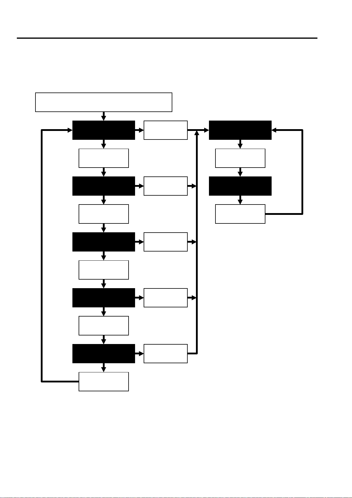
17-3. Compensation flow
)
The AJ-HDC27AP has Automatic blemish compensation function. Execution procedure of Automatic compensation
is shown below.
<DEFECT COMPENSATION>menu setting
Execute automatic com pensation
“<ENTRY (AUTO)> menu”
Automatic Blemish detection through compensation in whole
screen.
Result confirmation (at TV monitor)
Fine adjustment by cursor manually.
(Only when it cannot compensate completely by automatic
compensation
Store result of compensation (To built-in Memory)
(Only when executed manual adjustment)
INF-39
Page 42

17-4. Compensation Procedures
4-1. Initial setting (Menu setting of DEFECT COMPENSATON page)
Before start an adjustm ent, Set items (CAM SERVICE le vel) following portion. ( port ion , Sometimes it
isn’t possible to compensate blemish (es) in case of wrong setting.)
<DEFECT COMPENSATION>
COMPENSATION
®®®®
COMP ON GAIN
INTERACE MODE
R CH
G CH
B CH
TRIPLE OFFSET
CURSOR BOX
READ DATA
WRITE DATA
Figure Ble-1 Defect Compensation page
4-2. Execution of Automatic compensation (ENTRY (AUTO) page)
1. Open the “<DEFECT COMPENSATION> page” in CAM SERVICE level.
2. Set “COMP ON GAIN” item to des ired gain va lue. (Com pensation work s in the gain beyond the va lue set
up in this item.)
3. Open the “<ENTRY (AUTO) page>” in CAM SERVICE level.
4. Set the automatic c ompensation signal le vel (contrast ra tio *
AJ-HDC27AP detects blemish which bevel is more than the specified level by this set up.
: ON
: 12dB
: PDMIX
: AVE
: AVE
: AVE
: BAB
: ON
: OFF
: OFF
1
) with “PICKUP LEVEL R/ G or B” it em s. T he
<ENTRY (AUTO)>
PICKUP LEVEL R
®®®®
PICKUP LEVEL G
PICKUP LEVEL B
START
: 000
: 000
: 000
: OFF
NG LIST NO.
SELECT
ENTRY
CURSOR DISP
: 000
: OFF
: OFF
Figure Ble-2 ENTRY (AUTO) page
*1 contrast ratio: blemish signal level patio at the Built-in color
bars signal is 100%.
5. Set “START” item to ON by JOG DIAL in the unit. By this operation, The unit will execute blemish detection
for compensation in whole screen, automatically. And while executing automatic compensation, blink
“PICKUP” character on the lower right of the screen. (It takes about 30 seconds)
6. When “OK” character appears in the place of “PICKUP”, automatic compensation is completed.
7. Close menu screen and then turn off the power of the Unit. (Compensation result will be stored in the builtin memory of the Unit automatically.)
INF-40
Page 43

4-3. Result conf irmation
After execution of automatic compens ation the num ber of detection result and the number of blemish which
wasn’t compensated will be displayed in lower part of “ENTRY (AUTO)” page as the result status table. (Refer
to Figure Ble-3) P lease conf irm whether al l blem ishes were c ompens ated with th is status displa y by vie wing
the TV-monitor. As the standard of a confirmation, Blemish compensation specification is shown below.
LVL CNT
R
G
B
Y
015 003
010 006
025 004
001
NG 001
Figure Ble-3 Result status table
Observation enviro nment
Measurement part HD SDI OUT connector
Circumstance temperature
GAIN setting +18dB
AWB SW setting PRST (PRESET)
SETUP level 0%
Specification
LVL
CNT
NG
:
Display PICKUP LEVEL menu item’s value
:
The number of the points which were detected and
compensated as blemish(es). (Display the each color, “Y”
shows two or more blemishes were detected at the same
position)
:
The number of the position because that was which
wasn’t compensated in "compensation inhibition
position (refer to 5-4.)".
77°F (25°C)
Zone 2
Zone 1
H
4/5H
Contrast ratio*
1
Zone 1 Zone 2
0% - 8% No count No count
8% - 13% less than 2 less than 2
13% - 15% 0 less than 2
15% or more 0 0
*1 Contrast ratio: blemish signal level patio at the Built-in col or bars signal is 100%.
3/5V
V
INF-41
Page 44

4-4. Manual compensation procedure
In case it couldn’t com pensate all blemis h in automatic com pensation, it is also possible to perf orm blemis h
compensation manual ly b y using curs or. Follo win g shows c oncr ete m anual compensation procedur es by the
case required.
I ) Manual compensation for position which was not detected automatically
1. Close LENS iris and then execute “ABB” by front switch.
2. Open the “<DEFECT COMPENSATION> page” in CAM SERVICE level.
3. Set “COMP ON GAIN” item to desired gain value. (Compensation work s in the gain beyond the value se t
up in this item.)
4. Open the “<ENTRY (MANUAL) page>” in CAM SERVICE level.
5. Set menu items are shown below.
DEFECT SIZE : 3
GAIN : OFF
6. Set “DEFECT COLOR” item to R / G / B or Y, according to co lor of blemish. (If two or more color of
blemish appear in the same position, select “Y”.)
<ENTRY (MANUAL)>
H CURSOR COARSE
®®®®
H CURSOR FINE
V CURSOR COARSE
V CURSOR FINE
DEFECT SIZE
DEFECT COLOR
GAIN
OFFSET LEVEL A
OFFSET LEVEL B
ENTRY
CANCEL
Figure Ble-4 ENTRY (MANUAL) page
: 03
: 80
: 02
: 80
: 3
: Y
: OFF
: 100 (*2)
: 100 (*2)
: OFF
: OFF
7. Observe TV-monitor and then adjust “H CURSOR COARSE a nd FINE” item so that the H cursor position
comes to target blemish.
8. Observe TV-m onitor and then a dj ust “ V CUR SO R CO ARSE and FINE” it em so that the V cursor pos ition
comes to reduce the blemish.
9. Set “ENTRY” item to ON.
10. When “ENTRY” character appears on the lower right of the screen, data store will be completed.
11. Close menu screen and then turn off the power of the Unit.
NOTE:
*2 ”OFFSET A, B” menu ite ms don’t work in current camera system con t rol software Version T1.01-00-0.01, a s o f March/ ’01.
(A future schedule is undecided.)
INF-42
Page 45

II ) When compensation is fully impossible
In this case, there are two solutions by manual compensation.
a ) Re-setup of PICKUP LEVEL
1. Open “<ENTRY (AUTO)>” page in CAM SERVICE level.
2. Re-Setup “PICKUP LEVEL R/ G or B” items to level down (down detection level).
3. Execute automatic compensation again. (Set “START” item in “<ENTRY (AUTO)>” page to ON.)
b ) Fine adjustment of cursor position
1. Open “<EDIT / DELETE>” page in CAM SERVICE level.
2. Select Defect number desired position of fine cursor adjustment by “DEFECT NO.” item.
3. Set “DELETE” item to ON (turn JOG DIAL) and then press JOG DIAL.
4. Open “<ENTRY (MANUAL)>” page in CAM SERVICE level.
5. Set menu items are shown below.
DEFECT SIZE : 3
GAIN : OFF
6. Set “DEFECT COLOR” item to R / G / B or Y, acc ording to co lor of blem ish. (W hen two or m ore color of
blemish appear in the same position, select “Y”.)
<ENTRY (MANUAL)>
H CURSOR COARSE
®®®®
H CURSOR FINE
V CURSOR COARSE
V CURSOR FINE
DEFECT SIZE
DEFECT COLOR
GAIN
OFFSET LEVEL A
OFFSET LEVEL B
ENTRY
CANCEL
Figure Ble-5 ENTRY (MANUAL) page
: 03
: 80
: 02
: 80
: 3
: Y
: OFF
: 100
: 100
: OFF
: OFF
7. Observe TV-monitor and then adjust “H CURSOR COARSE a nd FINE” item so that the H cursor position
comes to target blemish.
8. Observe TV-m onitor and then a dj ust “ V CUR SO R CO ARSE and FINE” it em so that the V cursor pos ition
comes to reduce the blemish.
9. Set “ENTRY” item to ON (turn JOG DIAL) and then press JOG DIAL.
10. When “ENTRY” character appears on the lower right of the screen, data store will be completed.
11. Close menu screen and then turn off the power of the Unit.
INF-43
Page 46

17-5. Remarks
5-1. Delete all cursor position data in the built-in memory
1. Open “<EDIT / DELETE>” page in CAM SERVICE level.
2. Set “ALL DATA CLEAR?” item to ON by JOG DIAL operation.
3. Set “REALY ALL CLEAR?” item to ON by JOG DIAL operation.
4. When “ALL CLR” character appears on the lower right of the screen, data deletion will be completed.
5. Close menu screen and then turn off the power of the Unit.
5-2. Delete registered data one by one
1. Open “<EDIT / DELETE>” page in CAM SERVICE level.
2. Select “DEFECT NO.” to desired position of cursor.
3. Set “DELETE” item to ON by JOG DIAL operation.
4. When “DELETE” character appears on the lower right of the screen, data deletion will be completed.
5. Close menu screen and then turn off the power of the Unit.
5-3. Change Parameter about blemish compensation
1. Open “<EDIT / DELETE>” page in CAM SERVICE level.
2. Select “DEFECT NO.” to desired position of cursor.
3. Change some parameters in “<EDIT / DELETE>” page (DEFECT COLOR, DEFECT SIZE etc.).
4. Set “CHANGE” item to ON by JOG DIAL operation.
5. When “CHANGE” character appears on the lower right of the screen, data change will be completed.
6. Close menu screen and then turn off the power of the Unit.
5-4. About the position inhibited to register the compensation data
Depending on the posit ion for the blem ish compensation, blem ish compensation doesn’t work properly. In that
case, it display “NG” on the lower right position on the screen and inhibit registration of the blemish compensation
position. The condition “a)” is shown below.
a) : position of V CURSOR is the same line of the blemish compensated position and H cursor is +/- 2.
a)
Figure Ble-6 The position inhibited to register the compensation data
: Registered blemish compensation position
: Registration inhibited position
INF-44
Page 47

17-6. Trouble Shooting
Symptom Cause Check point
Blemish can’t be compensat ed
even COMPENSATION item
on menu is set to “ON”.
Blemish compensation posi tion
number (DEFECT No.) is
different from before.
“NG" display appeared on the
lower right of the screen when
trying to register a blemish
compensation position.
Wrong setting of fixed set ting
item.
DEFECT N o. is changed. DEFECT No. is automatically set fr om top left of monit or by the
Tried to execute registration
for the registrati on prohibited
position.
17-7. FAQ (Frequently Asked Question)
Question Answer
When execute blemish
compensation, Which
should I set to position
of GAIN SW on the
unit?
Can I store the blemish
compensation data as
backup to some place?
In the AJ-HDC27AP, GAIN setting while the blemish compensation used by only MENU setup.
·
Therefore you don’t have to set GAIN SW to some position.
By setting value of “COMP ON GAIN” item in the <DEFECT COMPENSATION> page, it is
·
possible to enable compensation in case of level more than the setting value on “COMP ON
GAIN” item.
When you want to enable the blemish compensation in all GAIN SW positions, Set “GAIN” item
·
in the ENTRY (MANUAL) menu page to OFF.
Yes
·
Normally , bl emish compe nsation dat a is s tored in IC201 (NV RAM ) on the CAM _SYS P.C.Board.
·
The AJ-HDC27AP is possible to store and read all blemish compensation data in IC202 (Flash
·
memory) on the CAM_ SYS P.C.Board as the BACKUP. by following operation in the DEFECT
COMPENSATION menu page.
<DEFECT COMPENSATION> page has items which must have
fixed setting.
Confirm if those items are fixed as factory default. (See "4-1.
Initial Setting” for details.)
direction of scanning. Therefore when new compensation
position is regis tered, another DEFECT No. may be c hanged.
Refer to the “5-4. About the position inhibited to register the
compensation data” page.
DATA WRITE: Set ”READ DATA” item to ON.
DATA READ: Set “WRITE DATA” item to ON.
Blemish compensation data is not stored to any extra media (SD CARD etc.)
·
INF-45
 Loading...