

Page 1
Operating Instructions
Multi Format Digital HD
Video Cassette Recorder
Model No. AJ-HD3700BP
(Supplement 2)
Model No. AJ-HD3700AP
(Supplement 3)
Model No. AJ-HD3700HP
(Supplement 6)
F0707N0 -F @
Printed in Japan
ENGLISH
VQT1K97
Page 2
Overview of changes and additions
This supplement describes the changes and additions to the operating instructions for the multi format digital HD
video cassette recorders AJ-HD3700B, AJ-HD3700A and AJ-HD3700H due to the introduction of the 2K
SYSTEM mode. For information on upgrading, contact the dealer where you purchased the product.
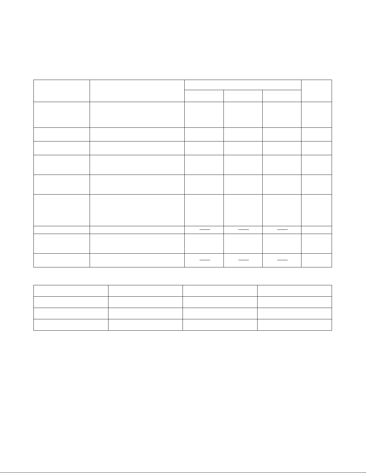
New changes and additions
Item concerned Change/addition
HOME • SYSTEM Status display
• TAPE Status display
• VIN/OUT Status display
Status display in 2K SYSTEM mode added.
SETUP F9 (2K) key.
2K SETUP function added.
VIDEO IN F2 (INT SG) key.
Alternatives in 2K SYSTEM mode added.
MULTI CUE SET UP F10 (MAX SP.) key.
Maximum value of variable speed in 2K
SYSTEM mode changed.
PANEL SET UP F12 (VAR MAX SP.) key.
Maximum value of variable speed in 2K
SYSTEM mode changed.
SYSTEM SET UP F3 (VIDEO) key.
Settings in 2K SYSTEM mode added.
F10 (COLOR SPACE) key.
Input formats (color space) in 2K SYSTEM
mode added.
2K SET UP 2K SYSTEM mode setting menus added.
TEST Addition of code to INSTALLED
SOFTWARE ID for indicating that 2K
SYSTEM mode is supported
2K error messages Error messages for 2K SYSTEM mode
added.
Page in the operating instructions Page
AJ-HD3700B AJ-HD3700A AJ-HD3700H
Software section,
Page 7
Software section,
Pages 5, 121
Software section,
Pages 22, 23
Software section,
Pages 95, 96
Software section,
Pages 128, 129
Software section,
Pages 140 to 143
Software section,
Page 151
Software section,
Page 7
Software section,
Pages 5, 116
Software section,
Pages 22, 23
Software section,
Pages 90, 91
Software section,
Pages 123, 124
Software section,
Pages 135 to 138
Software section,
Page 146
Software section,
Page 7
Software section,
Pages 5, 111
Software section,
Pages 22, 23
Software section,
Pages 85, 86 7
Software section,
Pages 118, 119 8
Software section,
Pages 130 to 133
Software section,
Page 138 12
in this
supplement
4
3, 5
6
9, 10
11
13, 14
Listed below are the software versions necessary to support these changes and additions.
FRONT SYSCON AV
HD3700B
HD3700A
HD3700H
FP-2.00.- or higher M1-2.00.- or higher M1-2.00.- or higher
FP-2.00.- or higher M1-2.00.- or higher M1-2.00.- or higher
FP-0.15.- or higher M1-2.00.- or higher M1-0.22.- or higher
z Limitations in 2K SYSTEM mode
In 2K SYSTEM mode, some menu items, such as settings for SD mode only, cannot be selected. For menu
items unavailable in 2K SYSTEM mode, refer to the lists described on page 15 and subsequent pages.
When the 2K system mode is set, the following I/O connectors are disabled or output errors occur.
• SD REF IN • SD REF OUT • HD REF OUT • VIDEO OUT • SD SDI IN
• SD SDI OUT • SD SDI MONITOR • HD SDI MONITOR • V/A CONTROL
z Switching method to the 2K system mode
To switch to the 2K system mode, select “2048 (PsF)” or “1920 (PsF)” in F3 (VIDEO) in SYSTEM SET UP
menu. (page 10)
- 2 -
Page 3
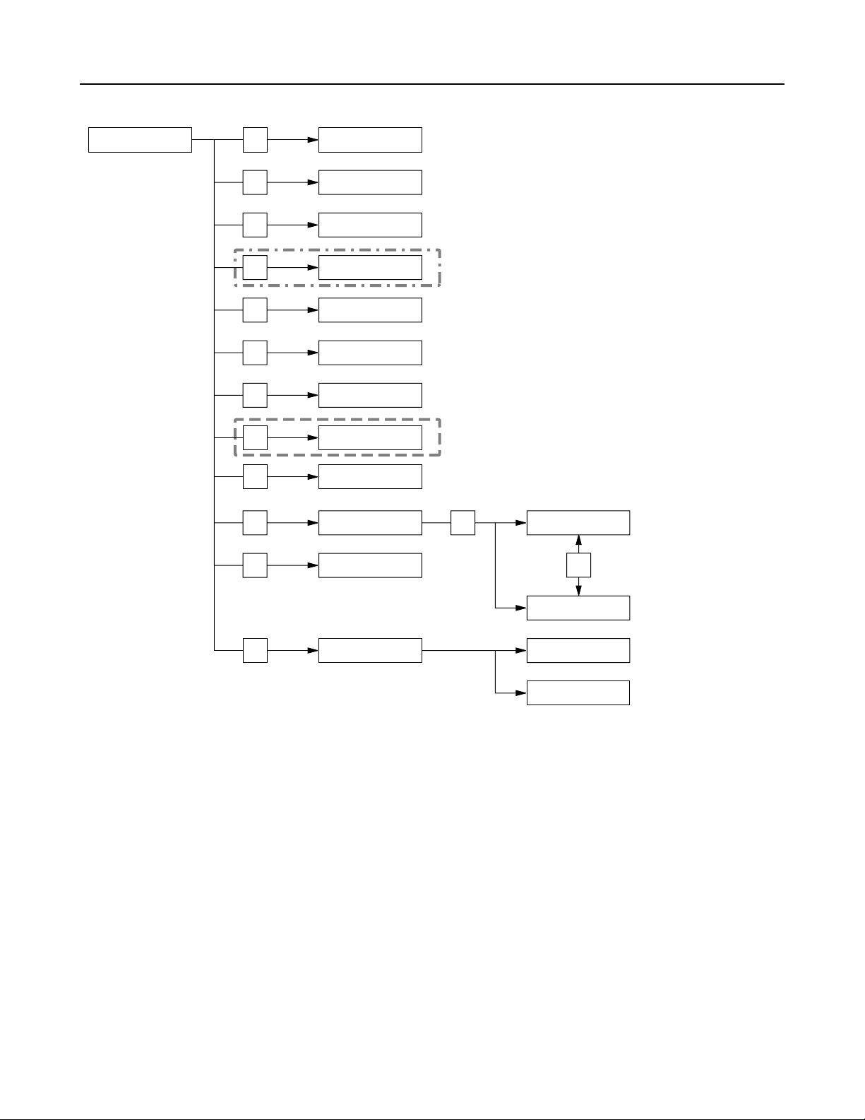
Menus added in the 2K system mode settings
SET UP
F1
F2
F3
F4
F5
F6
F7
F9
F10
F11
HOME SET UP
INSERT/ASSEMBLE
MANUAL EDIT SET UP
INSERT/ASSEMBLE
AUTO EDIT SET UP
SYSTEM SET UP
TC/CHR SET UP
AUDIO IN SET UP
AUDIO OUT SET UP
2K SET UP
INTERFACE SET UP
PANEL SET UP
System setup menu items for 2K SYSTEM mode
settings
Additional 2K SYSTEM mode setup menus
F11
OP MAP LOCAL
F12
F13
USER SET UP
OP MAP REMOTE
ENGINEER RF
OPERATION
F13
- 3 -
Page 4
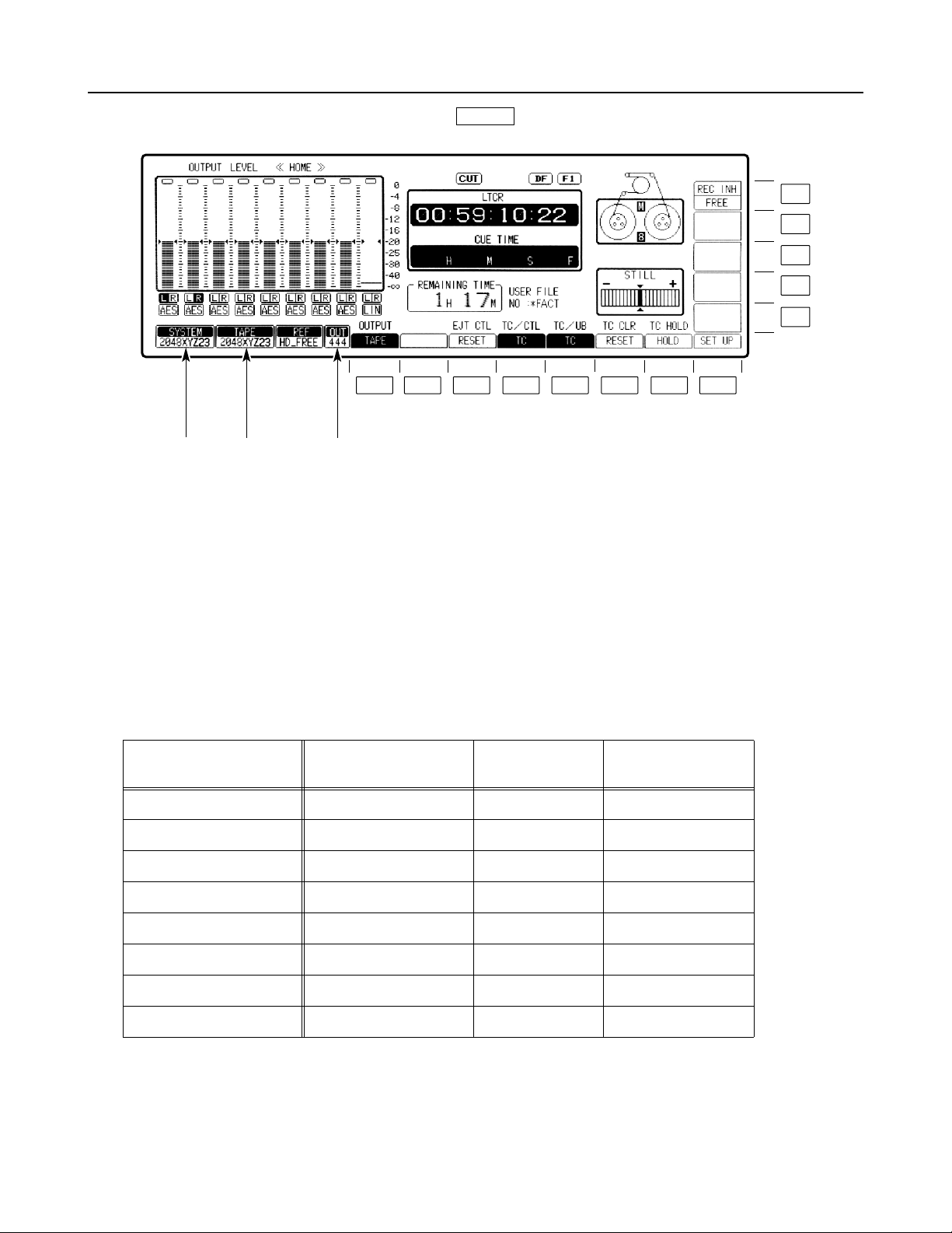
HOME menu
This menu is displayed by pressing the following key:
HOME
F8F7F6F5F4F3F2F1
!2"!1" !3"
!1" SYSTEM STATUS Display Area Displays 2K SYSTEM mode set in SYSTEM SET UP menu.
!2" TAPE STATUS Display Area Displays FORMAT ID of 2K SYSTEM mode recorded on tape.
F13
F12
F11
F10
F9
!3" VIN STATUS Display Area In 2K SYSTEM mode, this alternately displays VIN and the
SAMPLING value set in 2K SET UP, such as “444” and “422” as
OUT STATUS, at intervals of approximately 2 seconds (only in
the HOME menu).
2K system mode and 2K system mode TAPE ID to be displayed
2K SYSTEM MODE
/TAPE ID
2048RGB23 23.98 Hz 2048 RGB
2048RGB24 24 Hz 2048 RGB
2048XYZ23 23.98 Hz 2048 XYZ
2048XYZ24 24 Hz 2048 XYZ
1920RGB23 23.98 Hz 1920 RGB
1920RGB24 24 Hz 1920 RGB
1920XYZ23 23.98 Hz 1920 XYZ
1920XYZ24 24 Hz 1920 XYZ
SYSTEM
FREQUENCY
H SAMPLE COLOR SPACE
- 4 -
Page 5
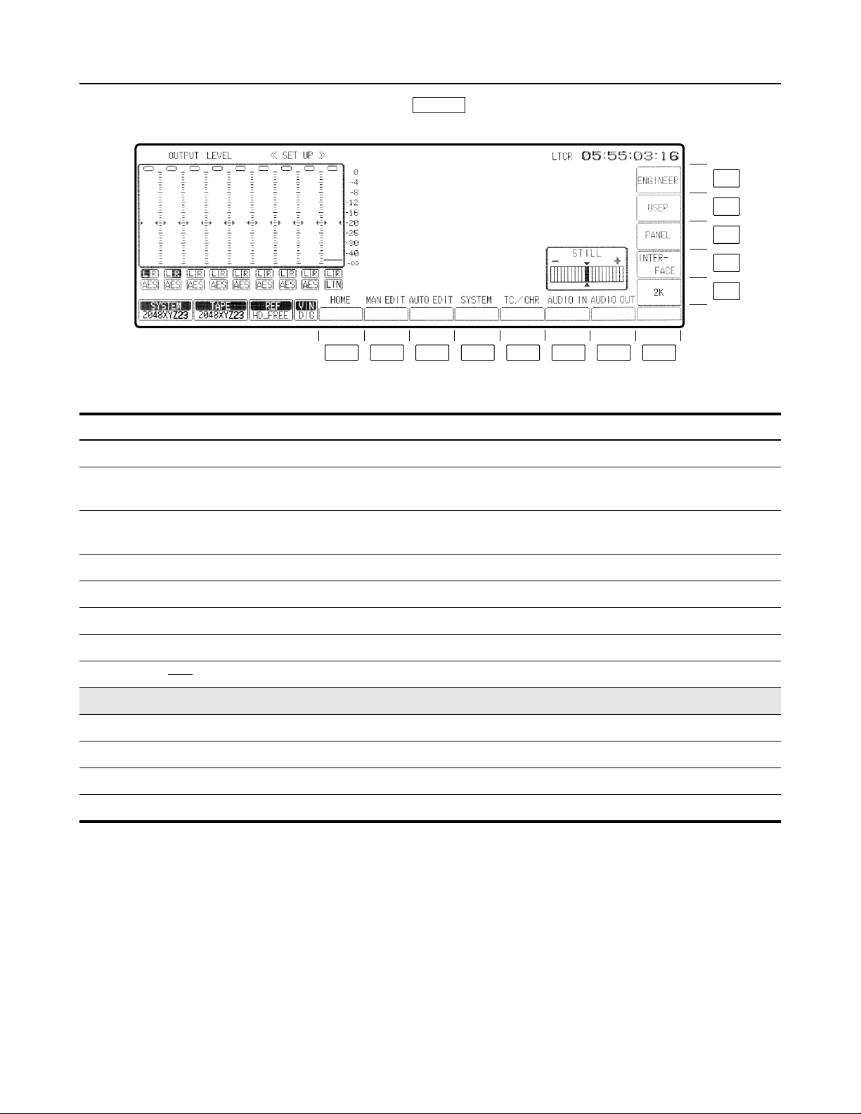
SET UP menu
This menu is displayed by pressing the following key:
SET UP
F13
F12
F11
F10
F9
F8F7F6F5F4F3F2F1
Key Key designation Description
F1 HOME Transfers the VTR to the HOME SET UP menu screen.
F2 MAN EDIT Transfers the VTR to the INSERT/ASSEMBLE MANUAL EDIT SET UP
menu screen.
F3 AUTO EDIT Transfers the VTR to the INSERT/ASSEMBLE AUTO EDIT SET
UP menu screen.
F4 SYSTEM Transfers the VTR to the SYSTEM SET UP menu screen.
F5 TC/CHR Transfers the VTR to the TC/CHR SET UP menu screen.
F6 AUDIO IN Transfers the VTR to the AUDIO IN SET UP menu screen.
F7 AUDIO OUT Transfers the VTR to the AUDIO OUT SET UP menu screen.
F8
F9 2K *
2
Transfers the VTR to the 2K SET UP menu screen.
F10 INTERFACE Transfers the VTR to the INTERFACE SET UP menu screen.
F11 PANEL Transfers the VTR to the PANEL SET UP menu screen.
F12 USER Transfers the VTR to the USER SET UP menu screen.
F13 ENGINEER *
*1The ENGINEER menu is displayed by pressing the F and F13 keys at the same time.
*2Additional menu item.
1
Transfers the VTR to the ENGINEER SET UP menu screen.
- 5 -
Page 6
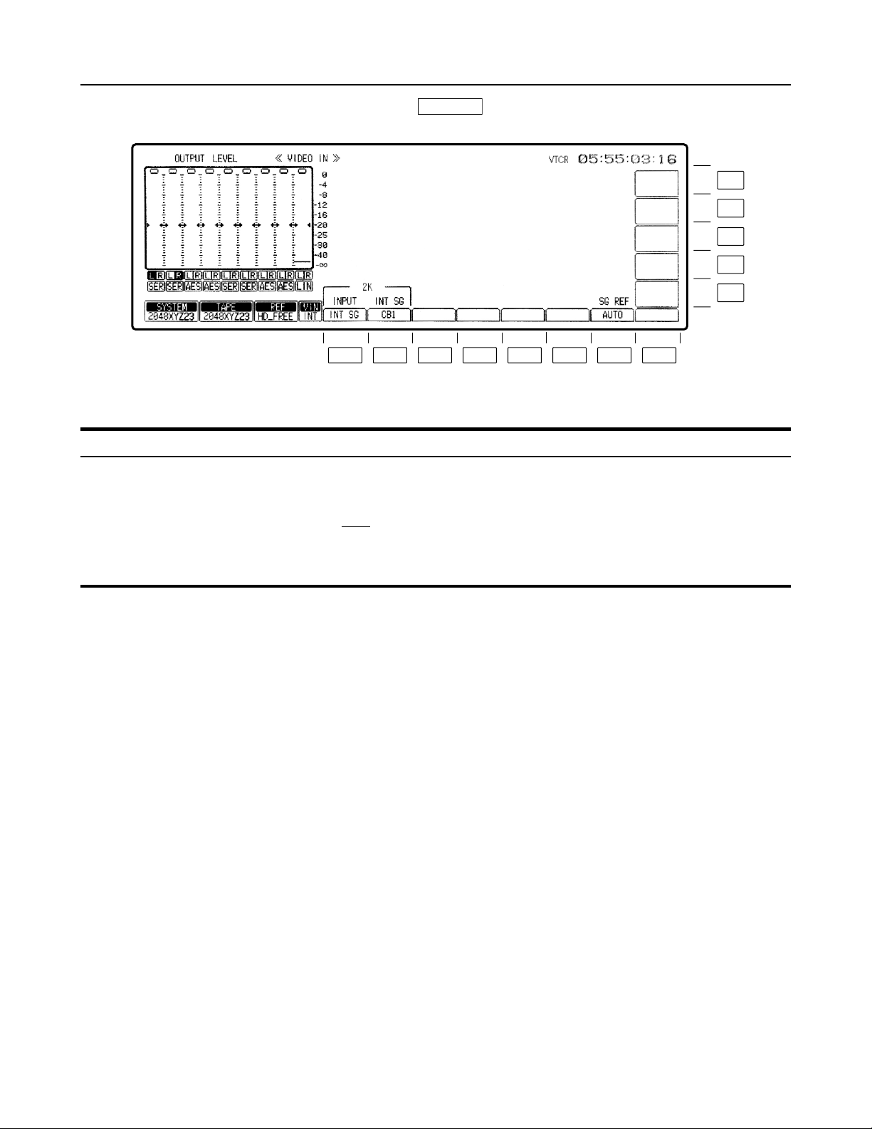
VIDEO IN menu
This menu is displayed by pressing the following key:
VIDEO IN
Key Key designation Description
F2 INT SG
For selecting the type of
HD internal signals.
<In 2K SYSTEM mode>
CB2: Selects the 75% color bar signal.(RGB)
Selects the color bar-2 signal.(XYZ)
CB1
: Selects the 100% color bar signal.(RGB)
Selects the color bar-1 signal.(XYZ)
BLACK: Selects the full-black signal.
WHITE: Selects the full-white signal.
F13
F12
F11
F10
F9
F8F7F6F5F4F3F2F1
The underlining indicates the default setting.
- 6 -
Page 7

MULTI CUE SET UP menu
This menu is displayed by pressing the following keys: )
MULTI CUE F8
Key Key designation Description
F10 MAX SP.
For setting the maximum
tape speed in the VAR
<In 2K SYSTEM mode>
j
1 ( )i1: Tape speed in the range of j1 to i1.
j0 ( )i1: Tape speed in the range of 0 to i1.
mode.
F13
F12
F11
F10
F9
F8F7F6F5F4F3F2F1
The underlining indicates the default setting.
- 7 -
Page 8

PANEL SET UP menu
This menu is displayed by pressing the following keys: )
SET UP F11
Key Key designation Description
F12 VAR MAX SP.
Variable maximum speed.
<In 2K SYSTEM mode>
1 ( )i1: Speed range from j1k to i1k.
j
j0 ( )i1: Speed range from 0k to i1k.
F13
F12
F11
F10
F9
F8F7F6F5F4F3F2F1
The underlining indicates the default setting.
- 8 -
Page 9

SYSTEM SET UP menu
This menu is displayed by pressing the following keys: )
SET UP F4
The system format and video output format currently set in the menu are displayed.
F13
F12
F11
F10
F9
F8F7F6F5F4F3F2F1
- 9 -
Page 10

SYSTEM SET UP menu
(Refer to the setting flowchart and output status tables on pages 144 and 145.)
As indicated in the procedures below, select the system frequency, video recording format, audio recording
format, and output formats for the output connectors to set the system format.
Key Key designation Description
F1 FREQ*
For selecting the SYSTEM
Frequency.
F3 VIDEO
For selecting the video
recording format.
For selecting the system frequency.
When the F1 key is pressed, the frequency selection window is opened.
The frequency can now be selected using the cursor keys.
59.94: The 59.94 Hz system is selected.
23.98
: The 23.98 Hz system is selected.
24: The 24 Hz system is selected.
50: The 50 Hz system is selected.
25: The 25 Hz system is selected.
The selection is entered by pressing the ENT key.
When the frequency setting has been selected, the video recording
format selection window is opened.
When the 23.98 or 24 setting has been selected, the selection window
which is 2K SYSTEM Format setting of H Sample is opened.
For selecting the video recording format.
When the F3 key is pressed, the video recording format selection
window is opened. Use the cursor keys to select the format.
In a set system frequency of “23.98” or “24”, select the format in the
following menu.
1080PsF
: The 1080PsF recording format is selected.
1080p: The 1080p recording format is selected.
2048 (PsF): The 2K system format of 2048 (PsF) 4:4:4 is selected.
1920 (PsF): The 2K system format of 1920 (PsF) 4:4:4 is selected.
To enter the selection, press the ENT key.
When the 1920 (PsF) or 2048 (PsF) setting has been selected, the
COLOR SPACE selection window is opened.
F5 HD SDI
(When the 2K system mode is
selected, this is displayed in
the window but cannot be
selected or set.)
F6 HD MONI
(When the 2K system mode is
selected, this is displayed in
the window but cannot be
selected or set.)
F7 SD SDI
(When the 2K system mode is
selected, this is displayed in
the window but cannot be
selected or set.)
F10 COLOR SPACE For selecting the color space used when 2K SYSTEM mode is selected.
RGB
: RGB color space is selected.
XYZ: XYZ color space is selected.
The underlining indicates the default setting.
* The FREQ setting is acknowledged only in the status where the cassette has been ejected.
If an attempt has been made to change this setting while a cassette is still inserted, the “EJECT CASSETTE TO
CHANGE FORMAT” message appears to warn the user to eject the cassette first.
- 10 -
Page 11

2K SET UP menu
This menu is displayed by pressing the following keys: )
SET UP F9
Key Key designation Description
F1 SAMPLING
For selecting the sampling format for DUAL Link SDI_OUT output signals.
This works by pressing the F button at the same time.
4:4:4: Output sampling format of 4:4:4 is selected.
4:2:2: Output sampling format of 4:2:2 is selected.
F2
F3 BIT LENGTH
(This item is displayed only
when “4:4:4” is selected in F1
(SAMPLING).)
For selecting the bit length of the output signal based on 4:4:4.
10bit: 10-bit processing is selected.
12bit
: 12-bit processing is selected.
F13
F12
F11
F10
F9
F8F7F6F5F4F3F2F1
F4
F5 H CROP
(This item is displayed when F3
(VIDEO) in the SYSTEM SET
UP menu is set to “2048 (PsF)”.)
For selecting the Crop format in the monitor output of 2048 mode.
CTR CROP
: Side_Crop is selected.
R CROP: Right_Crop is selected.
L CROP: Left_Crop is selected.
F6
F7 ROUNDING
(This is displayed in the setup
described on the right.)
When selecting an output sampling format of “4:4:4” for F1 (SAMPLING)
and “10bit” for F3 (BIT LENGTH), or selecting an output sampling format
of “4:2:2” for F1 (SAMPLING), decide whether or not to perform Dynamic
Rounding and select one of the following:
OFF: Dynamic Rounding is not performed.
ON: Dynamic Rounding is performed.
F8 EXIT Returns the VTR to the SET UP menu screen.
F9 H. REC. GRD
When the system settings in SYSTEM SET UP differ from the input signal in the
H Sample, decide whether or not to record and select one of the following.
OFF: Recording is performed.
(Recording is based on the value set for H Sample in the
system settings.)
ON: Recording is prohibited.
F10jF12
F13 CONNECT CHECK The LED for the AJ-HDP2000 blinks (for the regular SYSTEM
connection) only when the F13 key is pressed continuously.
When using several AJ-HD3700 B/A/H and AJ-HDP2000 units, this can
be used to check which unit connects to which counterpart.
The underlining indicates the default setting.
- 11 -
Page 12

TEST menu
This menu is displayed when the key is pressed.
TEST
A code indicating that 2K SYSTEM mode is supported was added to INSTALLED SOFTWARE ID.
F13
F12
F11
F10
F9
F8F7F6F5F4F3F2F1
INSTALLED SOFTWARE ID
AJ-HD3700BP-2K (1) < For AJ-HD3700B >
AJ-HD3700AP-2K (1) < For AJ-HD3700A >
AJ-HD3700HP-2K (1) < For AJ-HD3700H >
The code “(1)” displayed at the end indicates that 2K SYSTEM mode is supported.
When “(0)” or nothing is displayed and 2K SYSTEM mode is required, contact your dealer to upgrade the model.
- 12 -
Page 13

2K error messages
Error messages in the 2K system mode are added. In the event of an abnormal condition, an error message is
displayed in the window of the unit. In this case, follow any instructions included in the description.
If any errors are generated, the front LED (ALARM, 2048 or 1920) of the AJ-HDP2000 lights or blinks (at normal
speed or high speed).
F13
F12
F11
F10
F9
F8F7F6F5F4F3F2F1
AJ-HDP2000
Message Error description
ALARM LED
2048 or 1920
LED
2K FAN STOP The fan for the AJ-HDP2000 stops.
(Contact the nearest dealer.)
2K NO REMOTE Rear SERVICE SW of the AJ-HDP2000 is not in
the OFF position.
RECORDED FORMAT UNMATCH (NO J2K TAPE) TAPE is not compressed in J2K format.
RECORDED FORMAT UNMATCH There is a mismatch between SYSTEM
RECORDED RATE UNMATCH OUTPUT FRAME
FREQUENCY
CONCEAL V IN 2K An error occurs in 2K reproduction data and
NO SERIAL DATA INPUT FROM HDD5 Compressed SERIAL DATA (HD SDI) from
NO 2K FORMAT SERIAL DATA INPUT In 2K SYSTEM mode, the compressed SERIAL
CRC ERROR IN SERIAL DATA INPUT FROM
HDD5
NO EXTERNAL HD REF IN 2K HD REF IN is not connected.
FORMAT of the unit selected in settings and
FORMAT of TAPE. (2048/1920, XYZ/RGB)
There is a mismatch between the output frame
frequency and the frame frequency recorded on
the tape.
the CONCEAL function works.
AJ-HD3700B/A/H main unit is not linked.
DATA from AJ-HD3700B/A/H main unit is not a
J2K compression signal.
A CRC error occurs in SERIAL DATA (HD SDI)
signals from AJ-HD3700B/A/H main unit to
AJ-HDP2000.
Signals other than 1920 a 1080 (HD) tri-level
sync signal are transmitted to HD REF IN.
* If any warnings are generated while ERR/FMT or ERR are set in TC/CHR menu F13
(EX SUPER), “2K PROC ERROR” is displayed on SUPER of the Monitor OUT output.
- 13 -
: Lighting
: Fast Flashing
: Flashing
: Flashing with some setting
Page 14

2K error messages
Message Error description
AJ-HDP2000
ALARM LED
2048 or 1920
LED
REF IN SIGNAL UNMATCH SYSTEM
FREQUENCY
OUT OF RANGE OF SYSTEM PHASE BETWEEN
REF AND INPUT
INPUT SIGNAL UNMATCH SYSTEM FREQUENCY There is a mismatch in frame frequency between
COMMUNICATION ERROR BETWEEN 2K
PROCESSOR AND HDD5
NO DUAL LINK CHA 2K INPUT There is no input signal to Dual-Link IN Ach.
NO DUAL LINK CHB 2K INPUT There is no input signal to Dual-Link IN Bch.
SUBSTANDARD TIMING DIFFERENCE IN DUAL
LINK 2K INPUT
CRC ERROR IN DUAL LINK CHA 2K INPUT A CRC error occurs in signals on Dual-Link IN
CRC ERROR IN DUAL LINK CHB 2K INPUT A CRC error occurs in signals on Dual-Link IN
UNMATCH H SAMPLE BETWEEN INPUT SIGNAL
AND SYSTEM
DUAL LINK CHA 2K ASSIGNMENT IS CHB On Dual-Link IN Ach, Bch is added to the
There is a mismatch in frame frequency between
the SYSTEM set value and REF IN.
There is a large phase difference between the
input signal and REF IN. (w/o OUTREF:
the SYSTEM set value and the input signal.
A communication failure occurs between
AJ-HDP2000 and AJ-HD3700B/A/H.
Check that the connection between AJ-HDP2000
and AJ-HD3700B/A/H is correct.
The format of the input signals to Dual-Link IN
Ach is outside the specifications.
The format of the input signals to Dual-Link IN
Bch is outside the specifications.
The timing-phase difference of Dual-Link IN A/
Bch is outside the specifications (R 100 ns)
Ach.
Bch.
There is a mismatch in H SAMPLE between the
SYSTEM set value and the input signal.
Channel Assignment information in PAYLOAD of
the input signals.
INPUT)
DUAL LINK CHB 2K ASSIGNMENT IS CHA On Dual-Link IN Bch, Ach is added to the
DUAL LINK 2K INPUT FORMAT ASSIGNMENT IS
NOT PsF
D_LINK 2K INPUT COLOR SPACE ASSIGNMENT
UNMATCH SYSTEM
Channel Assignment information in PAYLOAD of
the input signals.
On Dual-Link IN A/Bch, the input signal format of
the PAYLOAD information is not PsF.
On Dual-Link IN A/Bch, color space information
of the input PAYLOAD signals does not match
the SYSTEM settings for the unit.
* If any warnings are generated while ERR/FMT or ERR are set in TC/CHR menu F13
(EX SUPER), “2K PROC ERROR” is displayed on SUPER of the Monitor OUT output.
- 14 -
: Lighting
: Fast Flashing
: Flashing
: Flashing with some setting
Page 15

Menu items unavailable in 2K SYSTEM mode
2
F
E
I
.
E
F3
C
OCK
5
CO
F
0
SD
S
E
SD
S
E
SD
SETUP SDI
SD
SETU
K
T
D
V
T
D
T
HD_TO_
S
F
H
F
I
SG
INPUT
F13
Y
Pb
F3
4
In “Menu screen transitions” described on page 4 of each operation instructions for the AJ-HD3700B, AJ-HD3700A,
and AJ-HD3700H, the following menu items cannot be selected.
HOME
VIDEO IN
VIDEO OUT HD
F
F8
REEZ
HOME SET UP
NT
F4
F
OUT REF
PRG PLY
PRG PLY
AP L
D RE
D RE
Menu items that cannot be selected
F1
F
9
F1
BLACK.L
SET UPF8
SD
NVERT
F7
VIDEO OUT
ETUP COMPOSIT
VIDEO OUT
ETUP STAT
VIDEO OUT
VIDEO OUT
P LINE BL
VIDEO OUT CONVER
HD_TO_S
IDEO OUT CONVER
SD_TO_H
VIDEO OUT CONVER
NTERP
STATEF12
HD
EJECT
STBY OFF
TENSION
RELEASE
EE MOD
FREEZE
FREEZE
- 15 -
Page 16

S
H
C
4
H
CH5
8
SD_TO_
C
SD_TO_SD
C
SD_TO_
C
4
SD_TO_SD
C
4
F5
F
F9
F
F10
F12
F13
F3J
.
1
C
1
C
CO
9TC/C
T
Z
F11
C
1
C
VITC
VITC
C/C
P
V
F9
F10
SIZE
F5
Menu items that cannot be selected
AUDIO OUT
TC/CHR
F9 SDI ASIGN
F8
SET UP
4
6
For AJ-HD3700B and AJ-HD3700A only
D_TO_SD
H1 -
D_TO_SD
-
D_AUD
HD
H5 - 8
HD
H1 -
H5 - 8
H1 -
.L
T
ITC.L
HR SET U
NVERTF
MULTI CUE F8
ASSEMBLE MANUAL EDIT F8 SET UP
INSERT MANUAL EDIT F8 SET UP
SET UP SYSTEM
F4
SET UP
AUTO EDIT F8 SET UP
AUTO EDIT F8 SET UP
HR CONVER
AUTO FR
PB AUTO
F1
F1
F1
AP LOCK
AP LOCK
AP LOCK
AP LOCK
F11
PANEL
OG MAX SP
- 16 -
Page 17

Menus not available on the AJ-HD3700H
For the AJ-HD3700H upgraded to support 2K SYSTEM mode, two menus (the TEST FRONT PANEL menu and
the TEST FRONT KEYCHECK menu) in the hierarchy below F6 (FRONT) of the TEST menu are deleted.
TEST
F2
F3
F4 MECHA
F5 SYSTEM
F6 FRONT
F7
F13 IC CARD
RF
AUDIO
SERVO
Menus that will be deleted during the upgrade to
support 2K SYSTEM mode (AJ-HD3700H only)
F1
F2
F1 USER
F2
PANEL
KEYCHECK
MULTI CUE
F1
F3
SELECT
MONITOR
DIAG
F3
F1
F2
F3
F1
DIAG MASKED
F2 F3
DIAG LAST
ERROR LOG
F2
MONITOR
- 17 -
Page 18

back
©
Panasonic Broadcast & Television Systems Company
Unit Company of Panasonic Corporation of North America
Executive Office:
One Panasonic Way 4E-7, Secaucus, NJ 07094 (201) 348-7000
EASTERN ZONE:
One Panasonic Way 4E-7, Secaucus, NJ 07094 (201) 348-7196
Southeast Region: (201) 348-7162
WESTERN ZONE:
3330 Cahuenga Blvd W., Los Angeles, CA 90068 (323) 436-3500
Government Marketing Department:
One Panasonic Way 2E-10, Secaucus, NJ 07094 (201) 348-7587
Broadcast PARTS INFORMATION & ORDERING:
9:00 a.m. – 5:00 p.m. (EST) (800) 334-4881/24 Hr. Fax (800) 334-4880
Emergency after hour parts orders (800) 334-4881
TECHNICAL SUPPORT:
Emergency 24 Hour Service (800) 222-0741
Panasonic Canada Inc.
5770 Ambler Drive, Mississauga, Ontario L4W 2T3 (905) 624-5010
Panasonic de Mexico S.A. de C.V.
Av angel Urraza Num. 1209 Col. de Valle 03100 Mexico, D.F. (52) 1 951 2127
Panasonic Puerto Rico Inc.
San Gabriel Industrial Park, 65th Infantry Ave., Km. 9.5, Carolina, Puerto Rico 00630 (787) 750-4300
2007 Matsushita Electric Industrial Co., Ltd. All Rights Reserved.
P
 Loading...