

Page 1

Digital Video Cassette Recorder
Operating Instructions
(Supplement 1)
AJ-
E
P
Page 2

Outline of changes and additions
This supplement describes what changes and additions have been made to the operating instructions of the
AJ-HD3700H digital video cassette recorder.
New changes and additions
Item concerned
Recording
HOME
VIDEO IN
TC/CHR
TC/CHR
CONVERT
SYSTEM SET UP
TEST IC CARD
TEST IC CARD
ERROR LOG
Change/addition
System frequency added
System frequency added
Internal signal generator (INT-SG)
synchronization
TC conversion function
Menu changed
True-P (Non-PsF) signal interface added
Date and time registration method
F7 (REAL TIME) key added
Page in AJ-HD3700H’s
operating instructions
Hardware section,
page 25
Software section,
page 8
Software section,
pages 22, 23
Software section,
pages 70 to 73
Software section,
page 80
Software section,
pages 130 to 132 and
135
Software section,
page 156
Software section,
page 161
Page in this
supplement
3, 4
5
6, 7
8 to 11
12, 13
14 to 17
18, 19
20
– 2 –
Page 3
Recording
This flowchart shows the steps for recording the digital signals which are supplied to the unit from an external
digital device.
11. Check the connections.
12. Turn on the power.
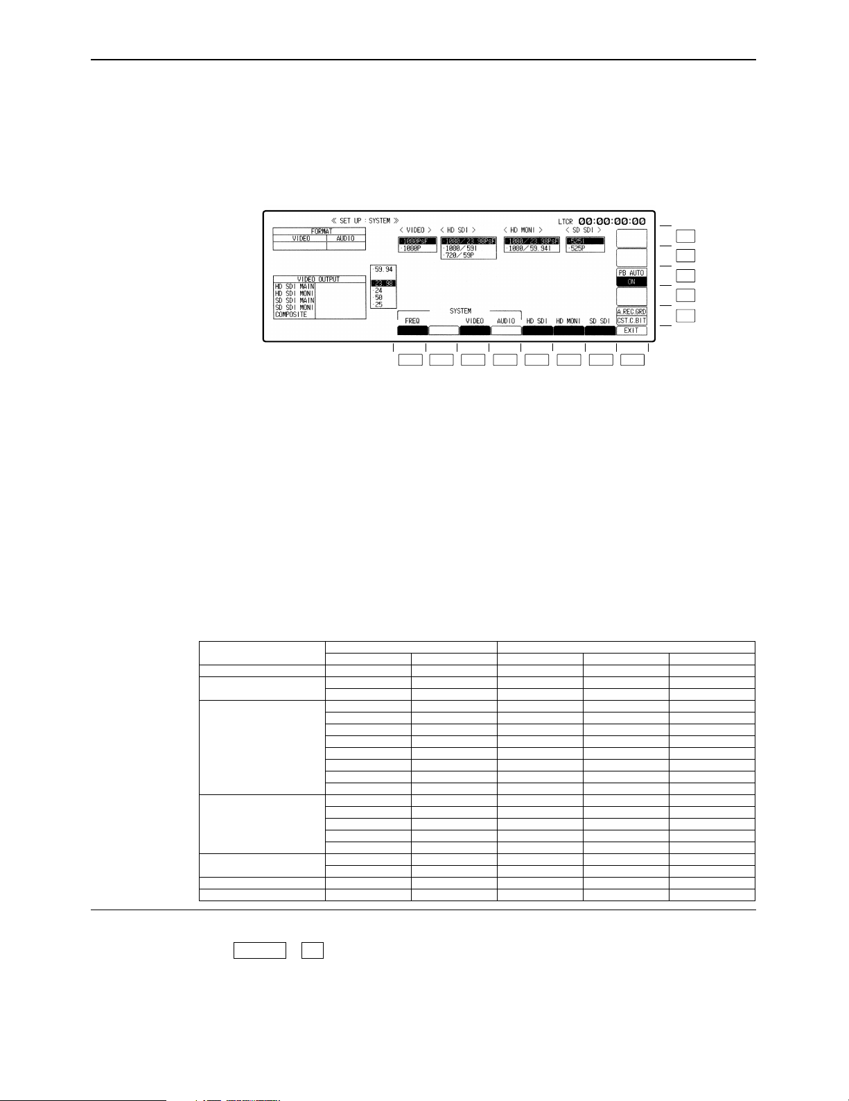
13. After making sure that no cassette tape is inserted in this unit, set the system frequency
59.94, 23.98, 24, 25 or 50 by F1 (FREQ) key of the SYSTEM SET UP menu.
F13
F12
F11
F10
F9
F8F7F6F5F4F3F2F1
The frequency setting is possible when the two keys, F and F1 are pressed at the same time.
Select the frequency by cursor key [3, 4] and press the BS and ENT keys at the same time,
then the frequency is secured. In 59 Hz mode, the selection window will be further displayed
(1080i/525i/720p). Select the format by the cursor key, and press the BS and ENT keys at
the same time to secure the format. When the 1080i or 720p format has been selected, select its 4-channel or 8-channel audio version, and enter the format by pressing the BS and
ENT keys at the same time.
In the 23.98 Hz, 24 Hz or 25 Hz mode, a window appears offering the user the option of selecting PsF or P for the VIDEO signal interface format. When the format is selected using the
cursor keys [3, 4] and the BS key and ENT key are then pressed together, the format is entered. In the same way, the HD MAIN output and HD MONI output formats are selected using
the cursor keys [3, 4] and then entered by pressing the BS key and ENT key together.
(The table below lists the possible combinations of the output signals of the video output
connectors. These combinations are available only when the AJ-UDC3700P option has
been installed.)
≥Output when a format converter has been installed
System format
1080/59.94i°
720/59.94p
1080/23.98p
1080/24.00p
1080/25p, PsF
2
1080/50i°
480/59.94i
1
1080/23.98PsF
1080/23.98PsF
1080/23.98PsF
HD MAIN
1080/59.94i
720/59.94p
720/59.94p
1080/23.98p
1080/59.94i
1080/59.94i
720/59.94p
720/59.94p
1080/24PsF
1080/24PsF
1080/24p
1080/60i
720/60p
1080/25PsF
1080/25p
1080/50i
1080/59.94i
HDTV output
HD MONI
1080/59.94i
720/59.94p
720/59.94p
1080/23.98PsF
1080/23.98PsF
1080/59.94i
1080/23.98p
1080/59.94i
1080/59.94i
720/59.94p
720/59.94p
1080/24PsF
1080/60i
1080/24p
1080/60i
720/60p
1080/25PsF
1080/25p
1080/50i
1080/59.94i
SD SDI MAIN
525/59.94i
525/59.94i
525/59.94p
525/59.94i
525/59.94p
——
525/59.94i
525/59.94i
525/59.94p
525/59.94i
525/59.94p
——
——
——
——
——
625/50i
625/50i
625/50i
525/59.94i
SDTV output
SD SDI MONI
525/59.94i
525/59.94i
525/59.94i
525/59.94i
525/59.94i
——
525/59.94i
525/59.94i
525/59.94i
525/59.94i
525/59.94i
——
——
——
——
——
625/50i
625/50i
625/50i
525/59.94i
Analog composite
NTSC
NTSC
NTSC
NTSC
NTSC
——
NTSC
NTSC
NTSC
NTSC
NTSC
——
——
——
——
——
PAL
PAL
PAL
NTSC
How to display the ≥SYSTEM SET UP menu:
menus:
°1The 1035/59.94i format signals cannot be recorded on this VTR but a tape recorded using the AJ-HD2000 or other model can
be played back.
°21080/23.98p 1080/25p and 1080/24p format tapes can be played back and 1080/50i format signals can be output automatically.
#
F4SET UP
– 3 –
Page 4

Recording
≥ The REF synchronization specifications applying when the 1080/23p, 24p or 25p True-P (Non-PsF) system
format is selected are the same specifications as for the PsF system format. Use an interlace format signal
for the HD tri-level SYNC signal.
≥ The True-P (Non-PsF) input/output interface does not support EMBEDDED AUDIO/TC/VANC.
≥ The enhance and filter response picture quality adjustments do not work for True-P (Non-PsF) outputs.
≥ Other signals cannot be superimposed onto HD monitor outputs using True-P signals.
≥ When PsF signals have been recorded using a PsF system format and they are subsequently played back
using a True-P system format, the PsF signals are converted into True-P signals. Conversely, when True-P
signals have been recorded using a True-P system format and they are subsequently played back using a
PsF system format, the True-P signals are converted into PsF signals.
≥ Bear in mind that when recording 1080/50i signals using the 1080/25PsF system format, the signals will be
recorded but the images will be blurred.
– 4 –
Page 5
HOME menu displays
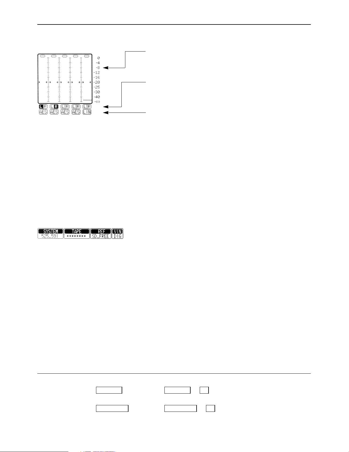
∑ Audio signal display area (Either 8 or 4 channels will be automatically displayed depending on the
format used.)
Use this to adjust the level of the input audio signals on the AUDIO
IN menu. Alternatively, it is used to adjust the level of the audio
playback output signals on the AUDIO OUT menu.
Press the L/R buttons to select the audio channel whose signals
are to be output from the AUDIO MONITOR L/R connectors and
HEADPHONES jack.
These display the type of input signals of each channel.
The F1 (CH-1) to F6 (DIGITAL) [or F1 (CH-1) to F13 (CH-8) for 8
channels] on the AUDIO IN PCM INPUT SELECT menu are selected using the F9 (CH-MIX) key on the AUDIO IN CUE INPUT
SELECT menu.
[----
ANA: Signals from the ANALOG INPUT connectors.
∑ Display lamps
CH1 AES:
T
CH1 SER: Signals from the serial V/A input connectors.
{---- INT: Signals from the internal signal generator.
[----
LINE: Signals from the CUE IN connector.
CUE MIX: CH1 to CH8 signals selected by CUE MIX setting.
{---- AUTO: This is always used for digital channel backup pur-
Signals from the DIGITAL AUDIO INPUT connectors.
poses.
SYSTEM: This indicates the video system format which was set
on the SETUP/SYSTEM menu.
1080_59i, 525_59i, 1080_23psf, 1080_23p,
1080_24psf, 1080_24p, 720_59p, 1080_50i, 1080_25p
TAPE: This indicates the format of the playback tape.
“¢¢¢¢¢¢¢¢” appears in the EJECT mode.
If a section is unrecorded or if the format of a section
cannot be identified, the lamp blinks while the display
of the format identified up to the section concerned is
retained.
1080_59i, 1080_60i, 1035_59i, 1035_60i, 525_59i,
1080_23p, 1080_24p, 720_59p, 720_60p, 1080_50i,
1080_25p
ONoteN
A tape recorded with the system format set to 1080/23.98psf or
1080/23.98p is recorded in the same tape format, and “1080_23p”
is displayed on the front panel when it is played back. Similarly,
“1080_24p” appears on the front panel with a tape recorded using
the 1080/24psf or 1080/24p system, and “1080_25p appears
when a tape recorded using the 1080/25psf or 1080/25p system.
How to display the ≥AUDIO IN menu: ≥AUDIO IN PCM INPUT SELECT menu:
menus:
≥AUDIO OUT menu: ≥AUDIO IN CUE INPUT SELECT menu:
AUDIO OUTAUDIO OUT
#
#
F6AUDIO INAUDIO IN
F7
– 5 –
Page 6
– 6 –
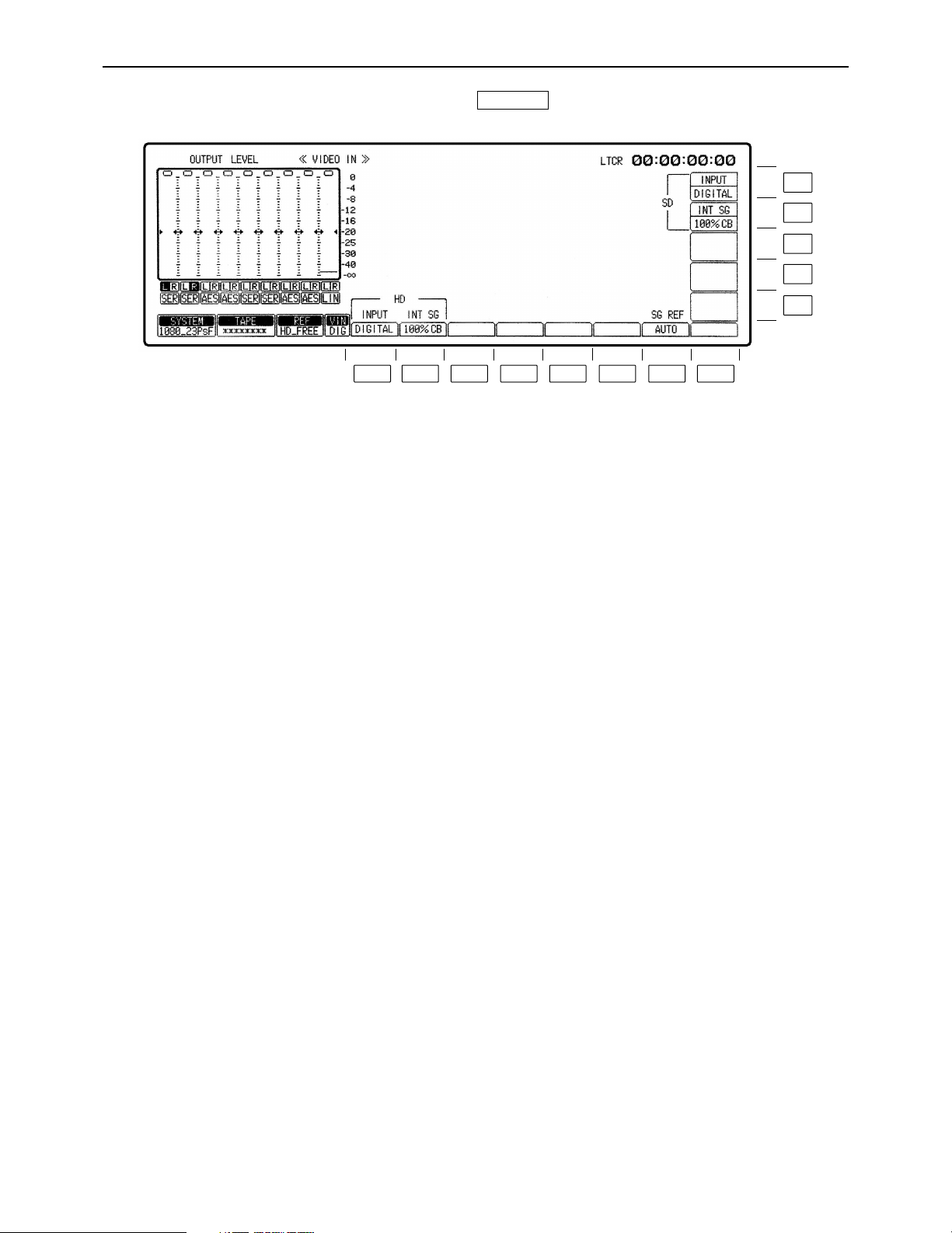
VIDEO IN menu
This menu is displayed by pressing the following key:
VIDEO IN
F13
F12
F11
F10
F9
F8F7F6F5F4F3F2F1
Page 7

– 7 –
VIDEO IN menu
Key
F1
F2
F3–F6
F7
F8–F11
F12
F13
Key designation
INPUT
For selecting the HD video
input signals.
INT SG
For selecting the type of
HD internal signals.
——
SG REF
For synchronizing the
INT SG
——
INT SG
For selecting the type of
SD internal signals.
INPUT
For selecting the SD video
input signals.
Description
DIGITAL: Selects the serial input signals.
INT SG: Selects the internal signals.
75% CB: Selects the 75% color bar signal.
100% CB: Selects the 100% color bar signal.
RAMP: Selects the RAMP signal.
MULT-BST: Selects the multi-burst signal.
BLACK: Selects the black-burst signal.
SIF PLL: Selects the signals for checking the serial
interface PLL.
SIF EQ: Selects the signal for checking the serial interface
equalizer.
SMPTE CB°1: Selects the SMPTE color bar signal.
AUTO: When video input signals are present, the internal
reference signal is locked to the input signals; when
video input signals are not present, it is locked to the
signal selected by the OUT REF setting°2.
OUTPUT: The internal reference signal is locked to the
signal selected by the OUT REF setting°2.
75% CB: Selects the 75% color bar signal.
100% CB: Selects the 100% color bar signal.
RAMP: Selects the RAMP signal.
MULT-BST: Selects the multi-burst signal.
BLACK: Selects the black-burst signal.
SIF PLL: Selects the signals for checking the serial interface
PLL.
SIF EQ: Selects the signal for checking the serial interface
equalizer.
SMPTE CB: Selects the SMPTE color bar signal.
DIGITAL: Selects the serial input signals.
INT SG: Selects the internal signals.
°1When the 720/59p format has been selected, the SMPTE CB function does not function.
°
2
Refer to the HOME SET UP menu.
Page 8

– 8 –
TC/CHR menu
This menu is displayed by pressing the following key:
TC/CHR
F13
F12
F11
F10
F9
F8F7F6F5F4F3F2F1
Page 9

– 9 –
TC/CHR menu
Description
INT: Built-in time code generator.
EXT LTC: LTC time code from TIME CODE input connector.
S LTC: LTC time code added to serial signals; not displayed
when the SD mode is selected.
S VTC: VTC time code added to serial signals; not
displayed when the SD mode is selected.
EXT VITC: VITC time code added to video signals; not
displayed when the HD mode is selected.
≥When the F1 (SOURCE) key is at [INT], AUTO, PRESET and
SALVE are displayed.
AUTO: Generator locks at the value read out by the
reader. In this case there is no time code setting.
(Only during editing.) During normal recording,
however, any setting of the generator can be
performed.
PRESET: Generator does not lock at the value read out by
the reader. Generator can be set freely.
SLAVE: The generator is locked to the reader’s readout
value. In this case, the time code cannot be set.
≥When the F1 (SOURCE) key is at [TEXT LTC], SALVE and
DIRECT are displayed.
SLAVE: Generator locks to external LTC time code.
(When there is no external input, E-TC time data
blinks. )
DIRECT: External LTC time code is recorded as is.
(When there is no external input, E-TC: ¢¢:¢¢:
¢¢:¢¢are displayed.)
≥When the F1 key is at [S VITC], [S LTC] or [EXT VITC], this key
is not displayed.
In this case, the generator value typically locks to external VITC
or LTC time code.
ON: User bit locks to user bit value read by reader (TCR) or to
external user bit value, and cannot be set.
OFF: Generator does not lock to value read out by reader. User
bit value can be set freely.
REC RUN: Runs the TC only while recording is in progress.
FREE RUN: Runs the TC all the time in the same way as a
clock.
Valid only when the F1 (SOURCE) key selects [INT].
ON: Drop frame mode is set.
OFF: Non-drop frame mode is set.
≥When [EXT LTC], [S VITC] or [S LTC] is selected in the F1
key, the VTR conforms to drop/non-drop frame mode of
external time code.
Key
F1
F2
F3
F4
F5
Key designation
SOURCE
For selecting
internal/external time code
signal.
TC SLAVE
For setting up time code
slave lock mode.
UB SLAVE
User bit lock.
RUN MD
Time code progress.
DF MD°
For selecting drop or
non-drop frame.
°This is not displayed when the 1080/23psf, 1080/23p, 1080/24psf, 1080/24p, 1080/25psf, 1080/25p or 1080/50i
system format has been selected.
Page 10

– 10 –
TC/CHR menu
Description
ON: CF BIT is recoorded.
OFF: CF BIT is not recorded.
≥When [EXT LTC], [S VITC] or [S LTC] is selected in the F1 key,
the VTR conforms to the external color frame bit.
Transfers the VTR to the TC/CHR SET UP menu screen.
Transfers the VTR to the TC/CHR CONVERT menu screen.
LTC: LTC is read out all the time.
AUTO: At low speed, VITC is read preferentially. When it is not
read, then LTC is read.
VITC: VITC is read out all the time.
≥In either setting, when the time code cannot be read, values
corrected by control signal are read out. (Interpolation mode is
assumed and [INTRP] is displayed on the HOME menu.)
TC.ST: The time code and VTR operating mode are
superimposed.
TC.ST.RT: The time code, VTR operating mode and remaining
tape time are superimposed.
TC.UB: The time code and user’s bit are superimposed.
TC.TC: The time code is displayed in two steps.
Both the original time code information and the time
code information in the format to which it has been
converted can be displayed at the same time. (Refer
to the note on the next page.)
TC: Only the time code is superimposed.
OFF: Nothing is superimposed.
ON: The warning displays are superimposed.
OFF: The warning displays are not superimposed.
REVERSE: Characters appear against a black background.
INTENSE: Characters are displayed more intensely.
Key
F6
F7
F8
F9
F10
F11
F12
F13
Key designation
CF BIT°
1
For selecting the color
frame bit ON/OFF during
recording.
——
SETUP
CONVERT°
2
TCR
For selecting time code
read out mode.
SUPER
For setting superimpose.
SUPER ERR
CHR TYPE
For selecting type of
character to be
superimosed.
°1This is displayed only when the 480/59.94i system format has been selected.
°
2
This is displayed only when the 1080/23psf, 1080/23p, 1080/24psf, 1080/24p, 1080/25psf, 1080/25p or 1080/50i
system format has been selected.
Page 11

– 11 –
TC/CHR menu
∑ Changing the superimposing position
(1) Move the position using the cursor keys.
≥When a cursor key is held down, the cursor will move more
quickly.
≥When the center cursor key is pressed, the superimposing re-
turns to its initial position.
∑ Time code displays and VTR’s operating modes
Display the time codes and VTR’s operating modes as required.
Time code displays
CTL1: Control signal 1 TCG: Value generated by time code generator
CTL2: Control signal 2 LUBG: Value of LTC user bit generated
LTCR: LTC time code readout value VUBG: Value of VITC user bit generated
LUBR: LTC user bit readout value EXTC: External time code value
VTCR: VITC time code readout value EXUB: External user bit value
VUBR: VITC user bit readout value
≥The colon (“:”) between the seconds and frames denotes the readout mode of the time code
reader.
Hours Minutes Seconds Frames
; ; ; ;
<Blinking display: Time code cannot be read out.
[. ]: DF mode ON
[: ]: DF mode OFF
[]: First field
[. ]: Second field
[: ]: Time code can be read out or TCG value is displayed.
[]: Time code cannot be read out.
Center cursor key
Cursor keys
This indicates that the time code is the original time code which was recorded on the tape.
If the time code displayed is not accompanied by this cassette mark, it means that the time
code is the post-conversion time code. (This display will go off when setting the CTL or UB.)
ONoteN
∑ 2-step display pattern with Time code setting
Upper 10:04:24:29
Lower 10:04:24:23
The converted time code is always displayed on the upper position, and the original or converted time code is
displayed on the lower position by selecting the time code.
The following pattern below is displayed by selecting the F11 or F12 key on the TC/CHR CONVERT menu.
1080/23p (psf),
1080/24p (psf) formats
Or
1080/25p (psf),
1080/50i formats
Or
Other formats
TC with frame count of 30
TC with frame count of 24
TC with frame count of 30
TC with frame count of 30
TC with frame count of 25
TC with frame count of 24
TC with frame count of 25
TC with frame count of 25
Original TC with frame count of 30
Original TC with frame count of 30
Page 12

– 12 –
TC/CHR CONVERT menu
∑ Concerning the TC SYNC value and sync phase settings
Since the TC is similarly converted when the 1080/23psf (p) or 1080/24psf (p) format is converted into the
1080/59i (480/59i) or 1080/60i format, it is necessary to input the time information (TC SYNC value) that will
serve as the reference for conversion and the 3:2 pull-down sequence (sync phase) of the post-conversion
output images.
∑ Setting the TC SYNC value
Input the pre-conversion TC with the frame count of 24 (24TC) and the post-conversion TC with the frame
count of 30 (30TC)/25 (25TC) to serve as the reference for conversion.
Page 13

– 13 –
TC/CHR CONVERT menu
This menu is displayed by pressing the following keys: ) When the center cursor key is
pressed, the 24TC display is highlighted. To enter the time code, use the number keys and cursor keys
(2, 1) to set the time code, and then press the key. Move on to the 30TC/25TC value setting using the
cursor keys (3, 4), and proceed in the same way to set and enter the time code.
ENT
F9TC/CHR
Key
F1–F2
F3
F4
F5
F6–F7
F8
F9
F10
F11
F12
F13
Key designation
——
SYNC PHASE°
——
DF MD°
——
EXIT
——
RC_TC°
SD SUPER
HD SUPER
LTC OUT°
Description
For setting the reference for the 3:2 conversion sequence.
A: Frame A is used as the reference to convert the time code.
B: Frame B is used as the reference to convert the time code.
C: Frame C is used as the reference to convert the time code.
D: Frame D is used as the reference to convert the time code.
For selecting whether the 3:2 pull-down output from the 1080/23psf
(p) or 1080/24psf (p) format after it is converted into the time code
and output is to be in the drop frame or non-drop frame mode.
DF: The output will be in the drop frame mode.
NDF: The output will be in the non-drop frame mode.
Returns the VTR to the TC/CHR menu screen.
For selecting the time code which is to be output to the remote
connectors (RS-422, etc.).
24TC: The original time code with the frame count of 24 is output.
30TC: The post-conversion time code with the frame count of 30
is output.
For selecting the time code which is to be output to the SD monitor connector.
24TC: The original time code with the frame count of 24 is output.
30TC/(25TC): The post-conversion time code with the frame
count of 30/(25) is output.
For selecting the time code which is to be output to the HD monitor
connector.
24TC: The original time code with the frame count of 24 is output.
30TC/(25TC): The post-conversion time code with the frame
count of 30/(25) is output.
For selecting the time code which is to be output to the LTC output connector.
24TC: The original time code with the frame count of 24 is output.
30TC: The post-conversion time code with the frame count of 30
is output.
°This is not displayed with the 50i/25psf (p).
F13
F12
F11
F10
F9
F8F7F6F5F4F3F2F1
Page 14

– 14 –
SYSTEM SET UP menu
This menu is displayed by pressing the following keys: )
The system format and video output format currently set in the menu are displayed.
F4SET UP
F13
F12
F11
F10
F9
F8F7F6F5F4F3F2F1
Page 15

– 15 –
SYSTEM SET UP menu
Refer to the setting flowchart and output status tables on pages 134 and 135.)
Exactly Which operation is performed differs depending on whether the AJ-UDC3700P HD-SD format converter board, an optional accessory, has been installed.
Key
F1
F2
F3
F4
Key designation
FREQ°
For selecting the SYSTEM
frequency.
——
VIDEO
For selecting the video
recording format.
AUDIO
For selecting the audio
recording format.
Description
For selecting the system frequency.
When the F1 key is pressed while holding down the F key, the
frequency selection window is opened. The frequency can now
be selected using the cursor keys.
59.94: The 59.94 Hz system is selected.
23.98: The 23.98 Hz system is selected.
24: The 24 Hz system is selected.
50: The 50 Hz system is selected.
25: The 25 Hz system is selected.
The selection is entered by pressing the ENT key while holding
down the BS key.
When “59.94” has been selected, the video recording format
selection window is opened.
When the 23.98, 24 or 25 setting has been selected, a window
enabling PsF or P (Non-PsF) to be selected is opened.
When the 23.98p or 24p (Non-PsF) format has been selected or when
the 50 format has been selected after the 25p or 25PsF format has
been entered, the system format is entered, and the window is closed.
For selecting the video recording format.
When the F3 key is pressed while holding down the F key, the video
recording format selection window is opened. Use the cursor keys to
select the format. One of the following menu items is selected when
59.94 has been selected as the system frequency setting.
1080I: The 1080/59.94i recording format is selected.
525I: The 525/59.94i recording format is selected.
720P: The 720/59.94p recording format is selected.
The selection is entered by pressing the ENT key while holding
down the BS key.
When “1080I” or “720P” has been selected, the audio recording
format selection window is opened.
When “525I” has been selected, the system format is entered as
525/59i, and the window is closed.
Select either PsF or P when 23.98, 24 or 25 has been selected
as the system frequency setting. To enter the selection, press
the ENT key while holding down the BS key.
For selecting the audio recording format.
When the F4 key is pressed while holding down the F key, the
audio recording format selection window is opened. The format
can now be selected using the cursor keys (but only when the
“1080/59I” or “720/59P” format has been selected).
24bit/8CH: The audio 8-channel format is selected.
20bit/4CH: The audio 4-channel format is selected.
The selection is entered by pressing the ENT key while holding
down the BS key.
When “720P” has been selected as the system format, the SD
SDI MAIN output selection window is opened.
When “1080I” has been selected as the system format, the
system format is entered, and the selection window is closed.
°The FREQ setting is acknowledged only in the status where the cassette has been ejected.
°If an attempt has been made to change this setting while a cassette is still inserted, the
“
EJECT CASSETTE TO
CHANGE FORMAT” message appears to warn the user to eject the cassette first.
Page 16

– 16 –
Key
F5
F6
Key designation
HD SDI
HD MONI
Description
For selecting the HD SDI MAIN output format.
When the F5 key is pressed while holding down the F key, the
HD SDI MAIN output format selection window is opened. The
format can now be selected using the cursor keys (but only when
“1080/23.98PsF” or “1080/24PsF” has been selected as the
system format).
1080/23.98PsF (1080/24PsF): The output is in the
1080/23.98PsF (1080/24PsF)
format.
1080/59.94I (1080/60I): The output is in the 1080/59.94i
(1080/60i) format.
720/59.94P (720/60P): The output is in the 1080/59.94p
(720/60p) format.
When “1080/23.98PsF (1080/24PsF)” has been selected, the HD
SDI monitor output selection window is opened.
When “1080/59I” or “720/59P” has been selected, the
HD_SDI_MAIN output selection window is opened.
When any other selection is made, it is entered by pressing the
ENT key while holding down the BS key. At the same time, the
window is closed
For selecting the format in which the signals are to be output to
the HD_SDI monitor.
When the F6 key is pressed while holding down the F key, the
HD_SDI monitor output selection window is opened. Use the
cursor keys to select the output format. (This format can be
selected only when the HD SDI main output has the same
setting as the system format and 1080/23.98PsF or 1080/24PsF
has been set.)
1080/23.98PsF (1080/24PsF): The output is in the
1080/23.98PsF (1080/24PsF)
format.
1080/59.94I (1080/60I): The output is in the 1080/59.94i
(1080/60i) format.
When “1080/23.98PsF (1080/24PsF)” has been selected, the HD
SDI MAIN output format selection window is opened.
When any other selection is made, it is entered by pressing the
ENT key while holding down the BS key. At the same time, the
window is closed.
SYSTEM SET UP menu
By pressing the C key while any of the selection windows are open, it is possible to return the selection
status to the previously set data. (Even when data has been entered by pressing the ENT key while the
BS key is held down, operation will still be as described above while the related windows are open.)
Page 17

– 17 –
SYSTEM SET UP menu
System format and video output status table
[When the AJ-UDC3700P HD-SD format converter board (optional accessory) has been installed]
F1: FREQ
59.94
23.98
24
25
50
F3: VIDEO
1080I
720P
525I
(1080PsF)
1080P
(1080PsF)
1080P
1080PsF
1080P
(1080I)
F4: AUDIO
4ch
8ch
4ch
8ch
(4ch)
(8ch)
(8ch)
(8ch)
(8ch)
(8ch)
(8ch)
(8ch)
F5: HD SDI
(1080/59.94i)
(720/59.94p)
(1080/59.94i)
1080/23.98psf
1080/59.94i
720/59.94p
(1080/23.98p)
1080/24psf
1080/60i
720/60p
1080/24p
1080/25psf
1080/25p
(1080/50i)
F6: HD MONI
(1080/59.94i)
(720/59.94p)
(1080/59.94i)
1080/23.98psf
1080/59.94i
(1080/59.94i)
720/59.94p
(1080/23.98p)
1080/24psf
1080/60i
(1080/60i)
720/60p
1080/24p
1080/25psf
1080/25p
(1080/50i)
F7: SD SDI
(525i)
525i
525p
525i
525p
(525i)
525i
525p
(°°°°)
525i
525p
525i
525p
(525i)
(°°°°)
(°°°°)
(°°°°)
(°°°°)
(°°°°)
(625i)
(625i)
(625i)
HD SDI OUT
1080/59.94i
720/59.94p
1080/59.94i
1080/23.98psf
1080/59.94i
720/59.94p
1080/23.98p
1080/24psf
1080/60i
720/60p
1080/24p
1080/25psf
1080/25p
1080/50i
HD MONI OUT
1080/59.94i
720/59.94p
1080/59.94i
1080/23.98psf
1080/59.94i
1080/59.94i
720/59.94p
1080/23.98p
1080/24psf
1080/60i
1080/60i
720/60p
1080/24p
1080/25psf
1080/25p
1080/50i
SD SDI OUT
525/59.94i
525/59.94i
525/59.94p
525/59.94i
525/59.94p
525/59.94i
525/59.94i
525/59.94p
No signals
525/59.94i
525/59.94p
525/59.94i
525/59.94p
525/59.94i
No signals
625/50i
625/50i
SD SDI MONI
525/59.94i
525/59.94i
525/59.94i
No signals
525/59.94i
525/59.94i
525/59.94i
525/59.94i
525/59.94i
No signals
625/50i
625/50i
CMPST
NTSC
NTSC
No signals
NTSC
No signals
PAL
PAL
System format front setting
System format and video output status table
[When no AJ-UDC3700P HD-SD format converter board (optional accessory) has been installed]
F1: FREQ
59.94
23.98
24
25
50
F3: VIDEO
1080I
720P
525I
(1080PsF)
1080P
(1080PsF)
1080P
(1080PsF)
1080P
(1080I)
F4: AUDIO
4ch
8ch
4ch
8ch
(4ch)
(8ch)
(8ch)
(8ch)
(8ch)
(8ch)
(8ch)
(8ch)
F5: HD SDI
(1080/59.94i)
(720/59.94p)
(°°°°)
(1080/23.98psf)
(1080/23.98p)
(1080/24psf)
(1080/24p)
(1080/25psf)
(1080/25p)
(1080/50i)
F6: HD MONI
(1080/59.94i)
(720/59.94p)
(°°°°)
(1080/23.98psf)
(1080/23.98p)
(1080/24psf)
(1080/24p)
(1080/25psf)
(1080/25p)
(1080/50i)
F7: SD SDI
(°°°°)
(°°°°)
525i
(°°°°)
(°°°°)
(°°°°)
(°°°°)
(°°°°)
(°°°°)
(°°°°)
HD SDI OUT
1080/59.94i
720/59.94p
BLACK
1080/23.98psf
1080/23.98p
1080/24psf
1080/24p
1080/25psf
1080/25p
1080/50i
HD MONI OUT
1080/59.94i
720/59.94p
BLACK
1080/23.98psf
1080/23.98p
1080/24psf
1080/24p
1080/25psf
1080/25p
1080/50i
SD SDI OUT
No signals
525/59.94i
No signals
SD SDI MONI
No signals
525/59.94i
No signals
CMPST
No signals
NTSC
No signals
System format front setting
ONoteN
The settings in parentheses cannot be selected since they are established automatically.
Page 18

– 18 –
TEST IC CARD menu
Preparations
When an error to be logged has occurred, this unit enables information on the date and time of the occurrence
of the error to be recorded in addition to the TC information in the log. Initial registration of the date and time
is required in order for this information to be recorded. Bear in mind that if the unit’s power has been off for
more than one week, it will be necessary to re-register the date and time.
How to register the date and time
When and then the key are pressed, a menu appears.
1. Press the center cursor key.
The year display at the top center of the front panel now appears as a white-on-black display.
2. Use the number keys to change the date and time.
Use the cursor keys (2, 1) to move the white-on-black display to the location where the information is to
be changed, and change the information using the number keys.
3. After having changed and registered the date and time information, press the ENT key to enter it.
F13TEST
°TEST IC CARD ERROR_LOG MONITOR menu
F13
F12
F11
F10
F9
F8F7F6F5F4F3F2F1
F13
F12
F11
F10
F9
F8F7F6F5F4F3F2F1
Page 19

– 19 –
TEST IC CARD menu
Description
User file management takes place using IC card.
When the F key is pressed, transfer is made to TEST IC CARD
USER FILE menu.
≥There is a load/save function for current (present deck status)
and all registered files.
≥When user file is forwarded to deck, whether SYS_H and
SYS_C should be sent together can be selected.
100 CUE_POINTS (MULTI_CUE) can be loaded/saved to IC
card.
When the F key is pressed, transfer is made to MULTICUE
menu.
≥Whether to send all at once or by page can be selected.
Function available for memory of deck mode, time code, type
and date/time when warning appears.
When the F3 key is pressed, the VTR is transferred to the TEST
IC CARD ERROR LOG menu.
≥Function available for 50-step memory data.
≥When memory buffer becomes full, there is a function for
switching to erasure of old material and renewal of new
warning.
≥Function available for memory storage of this data on IC card.
≥Function available to monitor IC card data.
Returns the VTR to the TEST menu screen.
IC card is formatted. Please note that all data on the IC card is
destroyed.
When the F key is pressed together with C key and F13
(FORMAT) key, the IC card is formatted.
Key
F1
F2
F3
F4– F7
F8
F9– F12
F13
Key designation
USER_FIL
MULT_CUE
ERR_LOG
——
EXIT
——
FORMAT
ONoteN
Avoid installing an IC card formatted by this unit in the AJ-HD2000/2700 or any other model.
Conversely, avoid installing an IC card formatted by any other model in this unit.
The file structure used for these cards is different from one model to another, and this may give rise to
problems in the VTR’s operation.
Page 20

– 20 –
TEST IC CARD ERROR LOG menu
This menu is displayed by pressing the following keys: >>
F3F13TEST
Description
Loads current memory data from VTR to IC card. In addition, the
serial No., software version and operation time are saved. If
there is no error log data in any file other than one containing the
machine current data (a file saved in the IC card or current data
of the VTR), “ERROR” appears, and the data cannot be
downloaded.
≥Executes when pressed together with F key.
Displays the error log data saved in the IC card.
After the machine current data (a file saved in the IC card or
current data of the VTR) has been downloaded, the error log
data currently stored in the VTR’s memory is displayed. (Refer to
ERROR_LOG MONITOR menu on page 18.)
≥Executes when pressed together with F key.
ERROR LOG data saved in IC card is deleted.
≥Executes when pressed together with F key.
When warning exceeds buffer capacity, selects whether to erase
old material sequentially and renew.
ON: Renews regularly. (The 50th step data is a latest data.)
OFF: No renewal when capacity is full.
ON: The date and time data are entered along with the TC data
in the error log.
OFF: The date and time data are not entered in the error log.
(Only the TC data is entered.)
Returns the VTR to the TEST IC CARD menu screen.
Deletes all the past error log data currently stored in the VTR’s
memory and all the error log data currently displayed.
When downloading is attempted after executing INITIAL with no
error log data, “ERROR” appears since there is no error log data,
and data cannot be downloaded to the IC card while the machine
current date can be downloaded.
Key
F1
F2
F3
F4
F5
F6
F7
F8
F9–F12
F13
Key designation
DOWN_LD
MONITOR
DELETE
——
AUTOSTEP
——
REAL TIME
EXIT
——
INITIAL
F13
F12
F11
F10
F9
F8F7F6F5F4F3F2F1
Page 21

– 21 –
Page 22

PANASONIC BROADCAST & TELEVISION SYSTEMS COMPANY
DIVISION OF MATSUSHITA ELECTRIC CORPORATION OF AMERICA
Executive Office:
3330 Cahuenga Blvd W., Los Angeles, CA 90068 (323) 436-3500
EASTERN ZONE:
One Panasonic Way 4E-7, Secaucus, NJ 07094 (201) 348-7621
Southeast Region:
1225 Northbrook Parkway, Ste 1-160, Suwanee, GA 30024 (770) 338-6835
Central Region:
1707 N Randall Road E1-C-1, Elgin, IL 60123 (847) 468-5200
WESTERN ZONE:
3330 Cahuenga Blvd W., Los Angeles, CA 90068 (323) 436-3500
Government Marketing Department:
52 West Gude Drive, Rockville, MD 20850 (301) 738-3840
Broadcast PARTS INFORMATION & ORDERING:
9:00 a.m.–5:00 p.m. (EST) (800) 334-4881/24 Hr. Fax (800) 334-4880
Emergency after hour parts orders (800) 334-4881
TECHNICAL SUPPORT:
Emergency 24 Hour Service (800) 222-0741
Panasonic Canada Inc.
5770 Ambler Drive, Mississauga, Ontario L4W 2T3 (905) 624-5010
Panasonic de Mexico S.A. de C.V.
Av angel Urraza Num. 1209 Col. de Valle 03100 Mexico, D.F. (52) 1 951 2127
Panasonic Sales Company
Division of Matsushita Electric of Puerto Rico Inc.
San Gabriel Industrial Park, 65th Infantry Ave., Km. 9.5, Carolina, Puerto Rico 00630 (787) 750-4300
Panasonic Broadcast Europe
Panasonic Broadcast Europe Ltd.
West Forest Gate, Wellington Road, Wokingham, Berkshire RG40 2AQ U.K. Tel: 0118 902 9200
Panasonic Broadcast Europe GmbH
Hagenauer Str. 43, 65203 Wiesbaden-Biebrich Deutschland Tel: 49-611-1816-0
Printed in Japan
VQT9803
F1201H
P E
 Loading...