

Panasonic AJ-HD1800E, AJ-HD1800P User Manual
Operating Instructions
Digital HD Video Cassette Recorder
Model No. AJ-HD1800P
Model No. AJ-HD1800E
Before operating this product, please read the instructions carefully and save this manual for future use.
F0907T0 -F @
Printed in Japan
ENGLISH
VQT1H81
Read this first!
For AJ-HD1800P and AJ-HD1800E
_THIS EQUIPMENT MUST BE GROUNDED
To ensure safe operation, the three-pin plug must be
inserted only into a standard three-pin power outlet
which is effectively grounded through normal
household wiring. Extension cords used with the
equipment must have three cores and be correctly
wired to provide connection to the ground. Wrongly
wired extension cords are a major cause of fatalities.
The fact that the equipment operates satisfactorily
does not imply that the power outlet is grounded or
that the installation is completely safe.
For your safety, if you are in any doubt about the
effective grounding of the power outlet, please consult
a qualified electrician.
CAUTION:
The mains plug of the power supply cord shall
remain readily operable.
The AC receptacle (mains socket outlet) shall
be installed near the equipment and shall be
easily accessible. To completely disconnect
this equipment from the AC mains, disconnect
the mains plug from the AC receptacle.
CAUTION:
z KEEP THE TEMPERATURE INSIDE THE
RACK BETWEEN 5°C to 40°C (41°F to 104°F).
z BOLT THE RACK SECURELY TO THE FLOOR
SO THAT IT WILL NOT TOPPLE OVER WHEN
THE UNIT IS DRAWN OUT.
CAUTION:
In order to maintain adequate ventilation, do not
install or place this unit in a bookcase, built-in
cabinet or any other confined space. To prevent risk
of electric shock or fire hazard due to overheating,
ensure that curtains and any other materials do not
obstruct the ventilation.
CAUTION:
TO REDUCE THE RISK OF FIRE OR SHOCK
HAZARD AND ANNOYING INTERFERENCE,
USE THE RECOMMENDED ACCESSORIES
ONLY.
WARNING:
z TO REDUCE THE RISK OF FIRE OR SHOCK
HAZARD, DO NOT EXPOSE THIS
EQUIPMENT TO RAIN OR MOISTURE.
z TO REDUCE THE RISK OF FIRE OR SHOCK
HAZARD, KEEP THIS EQUIPMENT AWAY
FROM ALL LIQUIDS. USE AND STORE ONLY
IN LOCATIONS WHICH ARE NOT EXPOSED
TO THE RISK OF DRIPPING OR SPLASHING
LIQUIDS, AND DO NOT PLACE ANY LIQUID
CONTAINERS ON TOP OF THE EQUIPMENT.
indicates safety information.
IMPORTANT
“Unauthorized recording of copyrighted
television programmes, video tapes and other
materials may infringe the rights of copyright
holders and contravene copyright laws.”
Operating precaution
Operation near any appliance which generates strong
magnetic fields may give rise to noise in the video and
audio signals. If this should be the case, deal with the
situation by, for instance, moving the source of the
magnetic fields away from the unit before operation.
2
Read this first! (continued)
For AJ-HD1800P
CAUTION
RISK OF ELECTRIC SHOCK
DO NOT OPEN
CAUTION: TO REDUCE THE RISK OF ELECTRIC SHOCK,
DO NOT REMOVE COVER (OR BACK).
REFER TO SERVICING TO QUALIFIED SERVICE PERSONNEL.
NO USER-SERVICEABLE PARTS INSIDE.
The lightning flash with arrowhead symbol,
within an equilateral triangle, is intended to
alert the user to the presence of uninsulated
“dangerous voltage” within the product’s
enclosure that may be of sufficient magnitude
to constitute a risk of electric shock to persons.
The exclamation point within an equilateral
triangle is intended to alert the user to the
presence of important operation and
maintenance (service) instructions in the
literature accompanying the appliance.
Notice (U.S.A. only):
This product has a fluorescent lamp that
contains a small amount of mercury. It also
contains lead in some components. Disposal
of these materials may be regulated in your
community due to environmental
considerations. For disposal or recycling
information, please contact your local
authorities, or the Electronics Industries
Alliance:
<http://www.eiae.org.>
FCC Note:
This equipment has been tested and found to comply
with the limits for a class A digital device, pursuant to
Part 15 of the FCC Rules. These limits are designed to
provide reasonable protection against harmful
interference when the equipment is operated in a
commercial environment. This equipment generates,
uses, and can radiate radio frequency energy, and if not
installed and used in accordance with the instruction
manual, may cause harmful interference to radio
communications. Operation of this equipment in a
residential area is likely to cause harmful interference in
which case the user will be required to correct the
interference at his own expense.
Warning:
To assure continued FCC emission limit compliance, the
user must use only shielded interface cables when
connecting to external units. Also, any unauthorized
changes or modifications to this equipment could void
the user’s authority to operate it.
CAUTION:
This apparatus can be operated at a voltage in
the range of 100 – 240 V AC.
Voltages other than 120 V are not intended for
U.S.A. and Canada.
CAUTION:
Operation at a voltage other than 120 V AC may
require the use of a different AC plug. Please
contact either a local or foreign Panasonic
authorized service center for assistance in
selecting an alternate AC plug.
indicates safety information.
3
Read this first! (continued)
For AJ-HD1800E
Caution for AC Mains Lead
FOR YOUR SAFETY PLEASE READ THE FOLLOWING TEXT CAREFULLY.
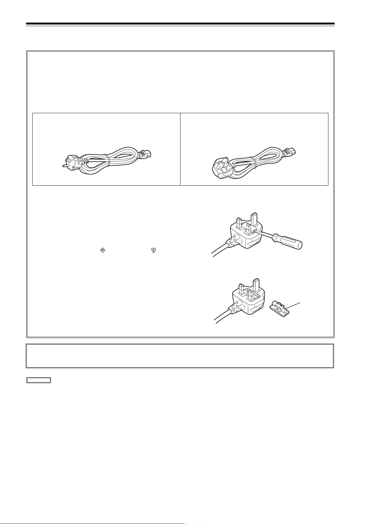
This product is equipped with 2 types of AC mains cable. One is for continental Europe, etc. and the other one is only
for U.K.
Appropriate mains cable must be used in each local area, since the other type of mains cable is not suitable.
FOR CONTINENTAL EUROPE, ETC.
Not to be used in the U.K.
FOR U.K. ONLY
This appliance is supplied with a moulded three pin mains
plug for your safety and convenience.
A 13 amp fuse is fitted in this plug.
Should the fuse need to be replaced please ensure that the
replacement fuse has a rating of 13 amps and that it is approved by ASTA or BSI to BS1362.
Check for the ASTA mark or the BSI mark on the
body of the fuse.
If the plug contains a removable fuse cover you must ensure that it is refitted when the fuse is replaced.
If you lose the fuse cover the plug must not be used until a
replacement cover is obtained.
A replacement fuse cover can be purchased from your local Panasonic Dealer.
FOR U.K. ONLY
If the plug supplied is not suitable for your socket outlet, it should be cut off and appropriate one fitted.
How to replace the fuse
1. Open the fuse compartment with a screwdriver.
2. Replace the fuse.
Fuse
DO NOT REMOVE PANEL COVERS BY UNSCREWING THEM.
To reduce the risk of electric shock, do not remove the covers. No user serviceable parts inside.
Refer servicing to qualified service personnel.
indicates safety information.
4

IMPORTANT SAFETY INSTRUCTIONS
1) Read these instructions.
2) Keep these instructions.
3) Heed all warnings.
4) Follow all instructions.
5) Do not use this apparatus near water.
6) Clean only with dry cloth.
7) Do not block any ventilation openings. Install in accordance with the manufacturerÅfs instructions.
8) Do not install near any heat sources such as radiators, heat registers, stoves, or other apparatus (including amplifiers) that
produce heat.
9) Do not defeat the safety purpose of the polarized or grounding-type plug. A polarized plug has two blades with one wider
than the other. A grounding-type plug has two blades and a third grounding prong. The wide blade or the third prong are
provided for your safety. If the provided plug does not fit into your outlet, consult an electrician for replacement of the
obsolete outlet.
10)Protect the power cord from being walked on or pinched particularly at plugs, convenience receptacles, and the point
where they exit from the apparatus.
11)Only use attachments/accessories specified by the manufacturer.
12)Use only with the cart, stand, tripod, bracket, or table specified by the manufacturer, or sold with the apparatus. When a
cart is used, use caution when moving the cart/ apparatus combination to avoid injury from tip-over.
13)Unplug this apparatus during lightning storms or when unused for long periods of time.
14)Refer all servicing to qualified service personnel. Servicing is required when the apparatus has been
damaged in any way, such as power-supply cord or plug is damaged, liquid has been spilled or objects
have fallen into the apparatus, the apparatus has been exposed to rain or moisture, does not operate
normally, or has been dropped.
Contents
Read this first! ...........................................2
General outline ..........................................7
Standard accessories ...............................7
Features......................................................8
Parts and their functions ........................10
Front panel (1) ....................................................10
Front panel (2) ....................................................11
Front panel (3) ....................................................12
Front panel (4) ....................................................13
Front panel (5) ....................................................14
Front panel (6) ....................................................15
Front panel (7) ....................................................16
Front panel (8) ....................................................17
Rear panel ..........................................................19
Connections.............................................21
Example of connections performed
for one VTR.........................................................21
Example of connections performed
for two VTRs (deck-to-deck) ...............................21
Example of connections in 23/24 Hz or 25/50 Hz
(HD) mode ..........................................................22
Example of connections in 25/50 Hz (SD)
mode ...................................................................22
Example of connections with an editing
controller .............................................................23
Turning on the power and
inserting the cassette..............................25
STOP and STANDBY modes ..................25
Recording.................................................26
Playback...................................................27
Playback phase adjustment function ..................27
Jog/Shuttle...............................................28
Jog Mode .........................................................28
Shuttle Mode ......................................................28
Manual Editing.........................................29
Preroll .......................................................29
Automatic Editing (deck-to-deck) ..........30
Switch settings and adjustments ........................30
Selecting the editing mode............................... 31
Registering the edit points................................ 31
Checking the edit points...................................32
Modifying edit points ........................................32
Previewing........................................................ 33
Automatic editing..............................................33
Reviewing......................................................... 33
Audio Split Editing ..................................34
Concerning tapes ....................................24
5

Contents (continued)
Variable memory function.......................36
Variable memory function selection..................36
Outline ..............................................................36
Variable memory playback operation
procedure..........................................................36
Variable memory editing operation
procedure..........................................................37
Function menus .......................................38
General description...........................................38
Allocating the function keys..............................39
<HOME>...........................................................40
<VIDEO>.............................................................49
<AUDIO> ..........................................................51
<TC> ...................................................................53
<CUE>..............................................................54
<DIAG> ...............................................................57
<MENU>...........................................................59
<ASSEMBLE>.....................................................60
<INSERT>...........................................................61
<SETUP MENU/SYSTEM MENU>.....................62
<FILE> ................................................................64
<PF1/PF2>..........................................................66
<CARD> ...........................................................71
<50P IN/OUT ASSIGN> ...................................74
Display saving function ........................123
Rack mounting.......................................124
Video head cleaning..............................125
Condensation.........................................125
Maintenance ...........................................125
Error messages......................................126
DIAG menu ....................................................126
Warning messages ........................................128
Error messages..............................................129
RS-232C interface ..................................131
Hardware specifications.................................131
Software specifications (protocol).................. 132
Connector signals .................................137
EMERGENCY EJECT .............................138
Specifications ........................................139
System menus .........................................80
Setup menus ............................................83
<BASIC>...........................................................83
<OPERATION> ................................................87
<INTERFACE> .................................................90
<EDIT> .............................................................91
<TAPE PROTECT> ..........................................93
<TIME CODE>..................................................94
<VIDEO> ..........................................................96
<AUDIO> ........................................................102
<DIF> ................................................................110
<MENU> ...........................................................111
<How to switch the system frequency>..........112
<Menu management accompanying
switching the system frequency>....................113
<Menus which are displayed>...........................113
Time code and user bits........................118
Time code.......................................................118
User bits..........................................................118
Setting the internal time code.........................118
Setting the external time code........................119
Cue time registration, preroll and cue-up........119
Time code and user bits playback..................119
Time code recorded on the unit ........................120
Superimpose screen .............................122
Selecting the audio recording channels
and monitor output................................123
Audio recording channels...............................123
Monitor output channels .................................123
6

General outline
This unit is a multi-format VTR capable of recording and
playing back HD signals (1080i/59.94 Hz, 1080i/50 Hz,
720p/59.94 Hz, 720p/50 Hz) in DVCPRO HD-LP* format
using a small cassette tape 1/4 inch wide, HD (DVCPRO
HD-LP/DVCPRO HD) and SD (DVCPRO50/DVCPRO)
recorded in DVCPRO format as well as conventional
consumer DV/DVCAM tapes.
A down-converter as a standard feature verifies all tapes
using analog composite signals and SD SDI output.
Furthermore, output signals converted to 1080/24PsF can
be obtained from the 720/24p over 60p source recorded with
the variable frame rate camera. These signals can be used
for cinema as well.
Similarly, each of the following output signals can be
obtained.
z 720/25p over 60p sources can be converted to 1080/25
PsF or 576i format output signals.
z 720/50p over 60p sources can be converted to 720/50p,
1080/50i or 576i format output signals.
Standard accessories
Power cord (AJ-HD1800P) 1
Power cord (AJ-HD1800E) 2
By mobilizing highly efficient digital compression technology
to assure a high picture quality, this VTR significantly
minimizes deterioration in the picture quality and sound
quality during the dubbing process.
It features a compact size of 4U and a lightweight design
that enables it to be carried around with ease, and to be
readily installed in a 19-inch rack.
The equipment is set up using an interactive system
whereby the operator manipulates the function buttons on
the front panel and observes the menu screens on the front
panel’s LCD monitor.
In terms of the editing features, this VTR is capable of both
assemble editing and insert editing.
* DVCPRO HD-LP has the same format as DVCPRO HD
EX described in the operation manual for our camera
recorder.
7

Features
Compact size and light weight
This is a 4U digital VTR. Using the rack-mounting
adapters (AJ-MA75P: optional accessory), it can also be
easily housed in a 19-inch rack.
Up to 126 minutes of recording
Using the DVCPRO HD-LP recording system, up to 126
minutes of material can be recorded on the 1/4-inch XLsize cassette tape.
High picture quality
The VTR’s high picture quality is achieved by 4:2:2 HD
component signal recording using a recording rate (100
Mbps) which is 4 times higher than that of the existing
DVCPRO format .
1080i/720p, 59.94 Hz/60 Hz/50 Hz signal switching
By making menu selections, the signals of the respective
formats can be recorded and played back.
No guarantees are made for the recording in 1080-60 Hz.
Frame rate conversion function
By making menu selections, the VTR can output signals
after converting them to the 1080/24PsF format when it
plays back a tape recorded by a variable frame rate
camera at a frame rate of 24fps.
When playing back a tape recorded at a frame rate of 25
fps, the tape’s signals can be converted to the 1080/25
PsF or 576i format and output. When playing back a tape
recorded at a frame rate of 50 fps, the tape signals can be
converted to the 1080/50i or 576i format and output.
<Notes>
z
Use tapes that are shot with a variable frame rate
camera.
z Do not use dubbed or edited tapes. The tape control
information may be lost, making it impossible to convert
the signals for playback.
Gamma correction of cinema for film
This feature corrects the image from a variable frame rate
camera in cinema gamma mode for film to an image with
film quality.
Digital slow motion/dial jog
Panasonic’s unique digital slow motion technology
enables clear playback (of tapes recorded using the
DVCPRO HD-LP system) at speeds ranging from j1k to
i2k.
<Note>
Some noise may occur during slow playback (using an
external controller) at speeds of almost exactly j1k or
i2k.
Search speed
Search speed enables tapes (recorded using the
DVCPRO HD-LP system) to be played back with color
images at speeds of up to 100 times in the forward or
reverse direction.
Time codes
This VTR comes with a built-in time code generator
(TCG)/time code reader (TCR).
In addition to the internal time code, an external time
code can also be input and recorded as the LTC on the
VTR.
UMID information recording and playback
This unit supports the recording/playback of UMID
(Unique Material Identifier) information in the SMPTE
330M standard. UMID information can be confirmed with
the diagnostic menu.
VTRs that do not support the recording/playback of
UMID information will not playback UMID information
correctly. In addition, when VTRs that do not support
recording/playback of UMID information are connected
to this unit, UMID information will not be recorded
correctly.
VANC data recording/playback
VANC data packets that added to the Y stream of HD SDI
can be recorded with the video signal. In addition, VANC
data packets can be played back with the Y stream of HD
SDI.
SDI interface
The VTR comes with an HD/SD serial digital interface as
a standard accessory.
Playback compatibility with DVCPRO systems
Besides DVCPRO HD-LP recording and playback, the
VTR can also play back tapes which have been recorded
using the existing DVCPRO HD, DVCPRO50 and
DVCPRO systems.
Consumer-use DV tapes (SP) and DVCAM tapes can
also be played back on this VTR.
8

Features (continued)
Multi-functional interfaces
z Serial digital input/output connector
The VTR comes with an HD component serial interface
input/output connector. This one BNC connector
enables HD component video signals and 8-channels
digital audio signals to be interfaced. (SMPTE 292M,
296M, 299M)
It is also equipped with an HD/SD format converter as
a standard accessory so that SD component serial
signals can also be output. (SMPTE 259M-C, 272MA, ITU-R BT.656-4)
z Analog video output connector
Composite signals are output during DVCPRO50- or
DVCPRO-compatible playback, DV playback, DVCAM
playback and down-conversion.
z AES/EBU audio input/output connectors
Digital audio input/output connectors for 8 channels are
featured as a standard accessory.
z Up-conversion recording of SD signals
SD component serial signals (SMPTE 259M-C, 272MA, ITU-R BT.656-4) can be up-converted and recorded
as HD signals.
8-channel high-sound-quality digital audio
The 8-channel PCM audio feature allows for not only
independent editing but mixing as well on all 8 channels.
One channel is provided for the analog cue track.
Menu-driven setup
The setup settings, which are conducted prior to
operating the VTR, are performed while the operator
views the setup menus either on the VTR’s LCD monitor
or on a TV monitor.
Multi-functional front panel with LCD monitor
The front panel’s multiple functions, including the LCD
monitor for monitoring images, the function buttons and
large-size display panel, are contained within the 4U
dimensions and designed to improve operating ease.
z 9-pin RS-422A and RS-232C remote control connec-
tors
In addition to the standard 9-pin serial remote (RS422A) control connector, the VTR is provided with RS232C and 50-pin parallel remote control connectors.
The RS-422A facility enables parallel operation if a loop
connection has been established between the VTR and
another VTR.
z IEEE1394 digital input/output
It is possible to input and output data in accordance
with the IEEE 1394 standard.
<Note>
INSERT and ASSEMBLE editing will not work when
[1394] is selected as the menu item No.600 (VIDEO IN
SEL).
<Playback formats and output formats>
Playback format Output format
DVCPRO HD-LP,
DVCPRO HD
DVCPRO50 DVCPRO50, DV
DVCPRO DVCPRO, DV
DV, DVCAM DV
In case of EE and REC modes:
<Note>
When any of the settings below is established, no signals
will be output from the IEEE1394 digital interface.
z When “60/24” is selected as the menu item No.030 HD
FREQUENCY setting
z When “23/24,” “25 (HD),” “25 (SD),” “50 (HD),” or “50
(SD)” is selected in menu item No. 025 SYSTEM
FREQ.
z
When the edit mode is selected while the output
DVCPRO HD,
DVCPRO50, DV
DVCPRO HD,
DVCPRO50, DV
format is set to other than DVCPRO HD.
9
Parts and their functions
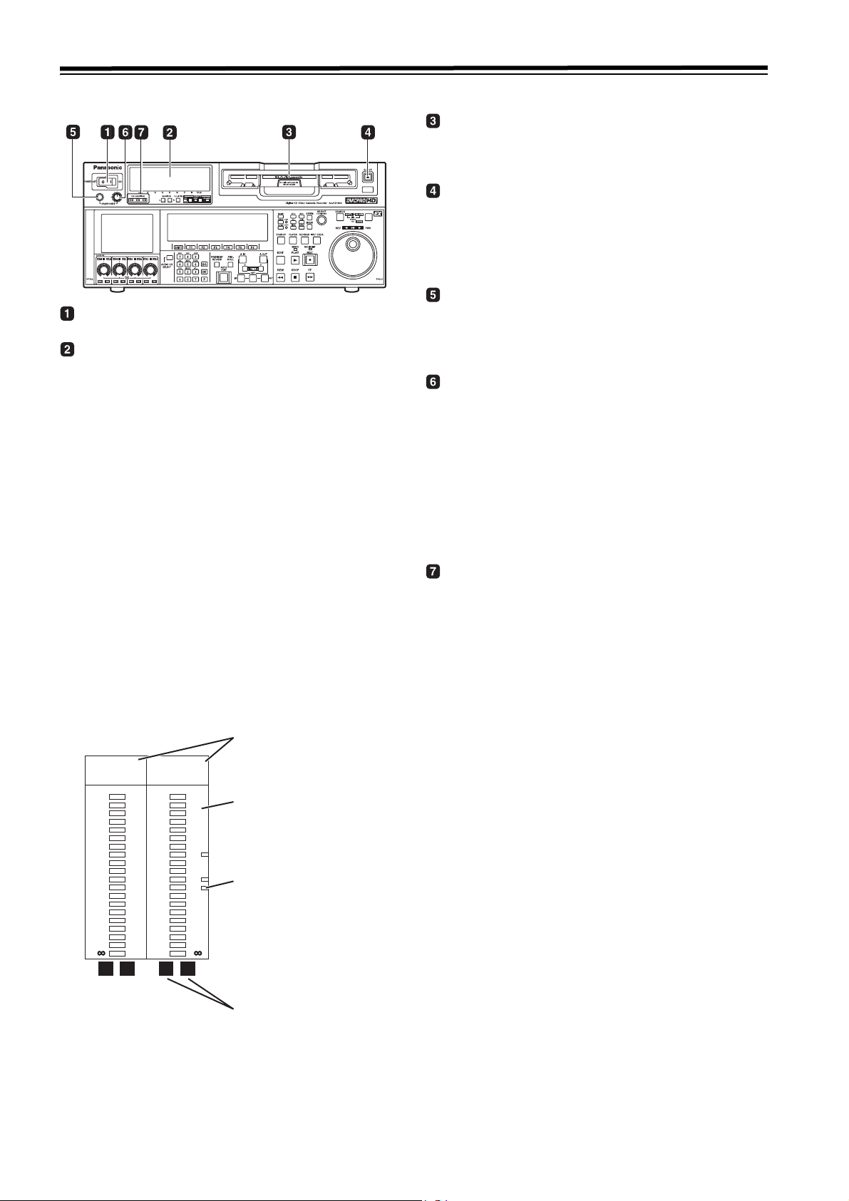
Front panel (1)
Cassette insertion slot
If the slot’s orange plate is visible, it means that a cassette
tape is already inserted.
EJECT button
When this button is pressed, the cassette is unloaded,
and a few seconds later it is ejected automatically.
When CTL appears on the counter display, the display is
reset.
Headphones jack
POWER switch
Audio level meter
The audio information is displayed here.
z The levels of the CH1, CH2, CH3, CH4, CH5, CH6,
CH7 and CH8 PCM audio signals and level of the CUE
track signal are displayed here.
z The levels of the input signals are displayed during
recording and when EE is selected.
During playback, the levels of the playback signals are
displayed. In the INPUT CHECK status, the levels of
the input signals are displayed for CH1 to CH8.
z Input signal display for each of the channels
The indicators for the selected input signals light.
(When the SD SDI input is selected, the SDI indicator
lights. When the 1394 input is selected, the HD lights.)
If no input signal is selected, the AES/HDSDI/SD SDI/
1394 indicator blinks while the ANA indicator lights continuously.
When the internal signal (INT SG) is selected, all AES/
ANA/HD SDI indicators light.
All indicators are off in 23/24 Hz mode or 25 Hz (HD,
SD) and 50 Hz (HD, SD) mode.
Input signal display
AES ANA
HD SDI
0
-
4
-
8
-
12
-
16
-
20
-
25
-
30
-
40
- -
L R
dB
•4
•3
•2
•1
0
-
-
-
-
1
2
3
4
AES ANA
HD SDI
dB
•16
-
16
-
17
•12
•8
-
18
-
19
•4
0
-
20
-
21
-
-
22
-
-
23
-
-
24
L R
Level meter
Reference
level indicator
5
10
20
The sound heard during recording, playback or editing
can be monitored through headphones when stereo
headphones are connected to this jack.
Volume control dial
This control dial is used to adjust the volume level of the
headphones and monitor output.
Whether the volume level of the monitor output is to be
coupled together with that of the headphones to this dial
or separated can be selected using the setup menu item
No.712 (MONI OUT). (Note that the volume level of the
headphones is coupled at all times.) When the volume
levels have been separated, the UNITY value (prescribed
value) applies to the monitor output.
Channel condition lamps
These lamps light to indicate the error rate status.
(Green>amber>red)
Green: This lights when the error rates for the video and
Amber:
Red: This lights when correction or interpolation has
audio playback signals are both at acceptable
levels.
This lights when the error rate for either the video
or audio playback signals has deteriorated. The
playback picture and sound remain unaffected
even while this lamp is lighted.
been engaged for either the video or audio
playback signals.
10
Left (L) and right (R)
monitor channel
Parts and their functions (continued)
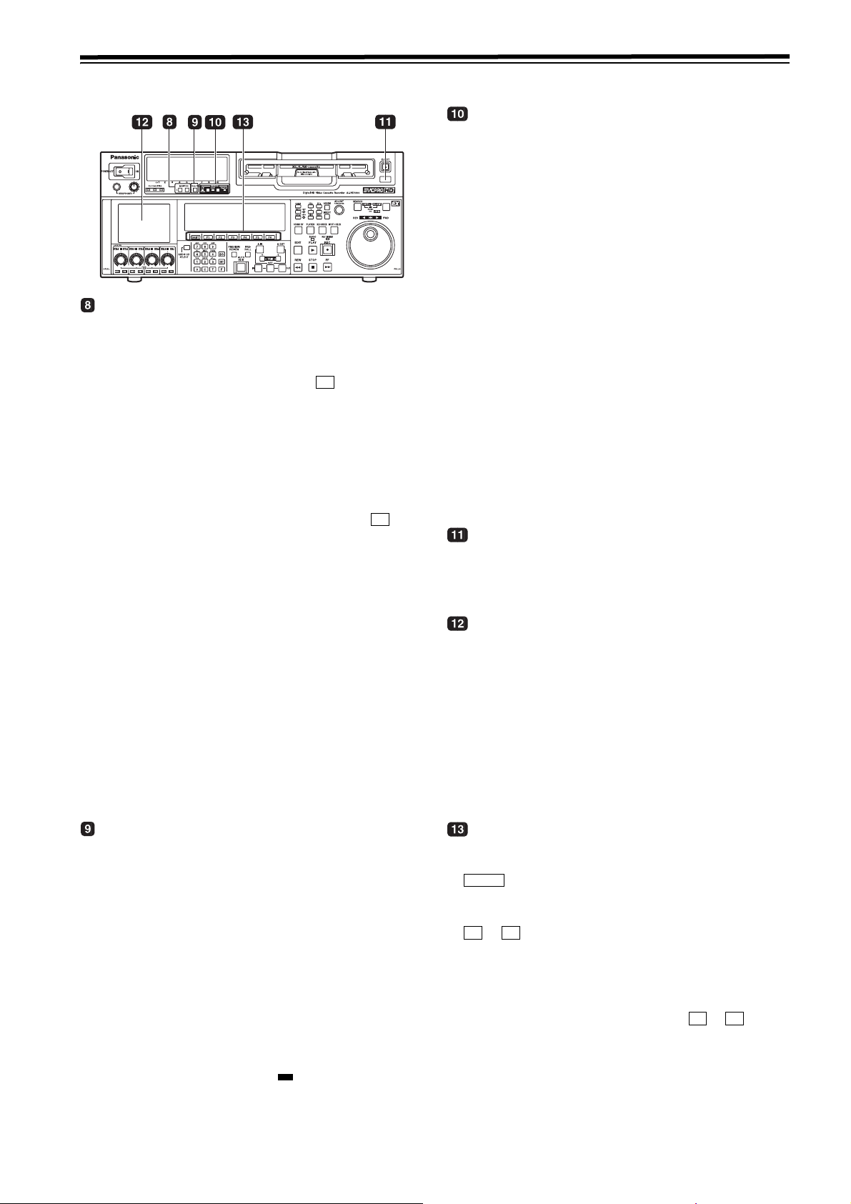
Front panel (2)
MONITOR SELECT buttons
These buttons are used to select the audio signals which
are to be output to the monitor L and R connectors and
headphones jack.
z
When OFF has been selected as the M MIX setting
on the <AUDIO SHIFT2> menu (factory setting):
Each time the L (or R) button is pressed, the
signal to be output to the monitor L (or R)
connector is changed in the following sequence
and displayed on the audio level meter: CH1 >
CH2 > CH3> CH4 > CH5 > CH6 > CH7 >
CH8 > CUE > CH1, etc.
z When L, R or L/R has been selected as the M
MIX setting on the <AUDIO SHIFT2> menu:
At this setting, the signals of a multiple number of
channels can be mixed and output.
When the number key corresponding to the
channel whose signals are to be monitored is
pressed while the L (or R) button is held down,
that channel is selected and its signals are
displayed on the audio level meter. By
performing the same operation, the selected
channel can be de-selected.
However, a maximum of only two channels from
CH1 to CH4 and a maximum of only two
channels from CH5 to CH8 can be selected.
Example of channels which can be selected:
CH1 i CH3 i CH5 iCH8 > OK
CH1 + CH2 + CH4 > NG
F6
F6
REMOTE buttons and RS-232C display
These buttons are used when this VTR is to be controlled
from an external component using the REMOTE, RS232C or parallel connector.
9P 1394:
Press the button for 2 seconds or more, the LED
lights, and the unit can be controlled by a device
connected through the REMOTE connector, the
(IN/O
UT) connector, or the DVCPRO/DV
connector. Release the control by pressing the
button for 2 seconds or more.
50P: When this button is pressed for 2 or more
seconds, its LED lights, and it is possible to
control the VTR from a unit which has been
connected using the 50-pin parallel mode
connector. Release the control by pressing the
button for 2 seconds or more.
RS-232C display:
This LED lights when communication has been
enabled between the VTR and the unit which has
been connected to the RS-232C connector. The
display can be switched in SETUP MENU No.204
(RS232C SEL).
AUTO OFF lamp
This lamp lights when a problem has occurred with the
VTR’s operation, and details of the problem appear on the
time code display.
LCD monitor
The monitor is operated as a simple monitor for playing
back tapes or displaying EE images and menu display.
If the VTR is left in a state where no controls on the front
panel are operated or where the tape is not running, the
monitor display is automatically turned off in order to
protect the monitor. When the next VTR operation is
started, the monitor display comes back on.
<Note>
Some images may not be displayed. Use another monitor
to check the images.
METER (FULL/FINE) selector button
This button is used to select the scale display for the
audio level meter.
FULL mode:
According to the settings in SETUP MENU No.
763 (METER SCALE)*, the range from
to 0 dB or the range from
j∞ dB to +20 dB is
displayed.
FINE mode:
According to the settings in SETUP MENU No.
763 (METER SCALE)*, the range from j24 dB to
j15 dB or the range from j4 dB to +5 is
displayed at intervals of every 0.5 dB.
The reference level is displayed with the
reference level indicator on the right side of the
level meter. The reference level can be changed
in SETUP MENU No. 776 (REF LEVEL)
* This menu is not displayed for AJ-HD1800E.
j∞ dB
Function buttons
These buttons operate the function menu (refer to page
38).
SHIFT
:
This is used to switch pages on the current
function menu.
F1 F6
to :
These are used to change the settings of the
setting items enclosed in the frame at the bottom
of the time code display.
To change a setting, keep pressing the
corresponding function button ( to ) until
the desired numerical value appears;
alternatively, press the corresponding function
button to highlight the setting of the setting item,
and then turn the ADJUST dial until the desired
numerical value is obtained.
F1 F6
11
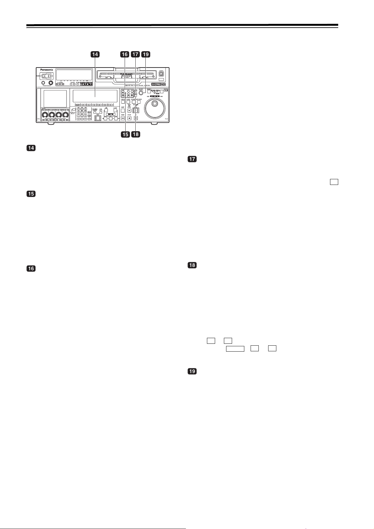
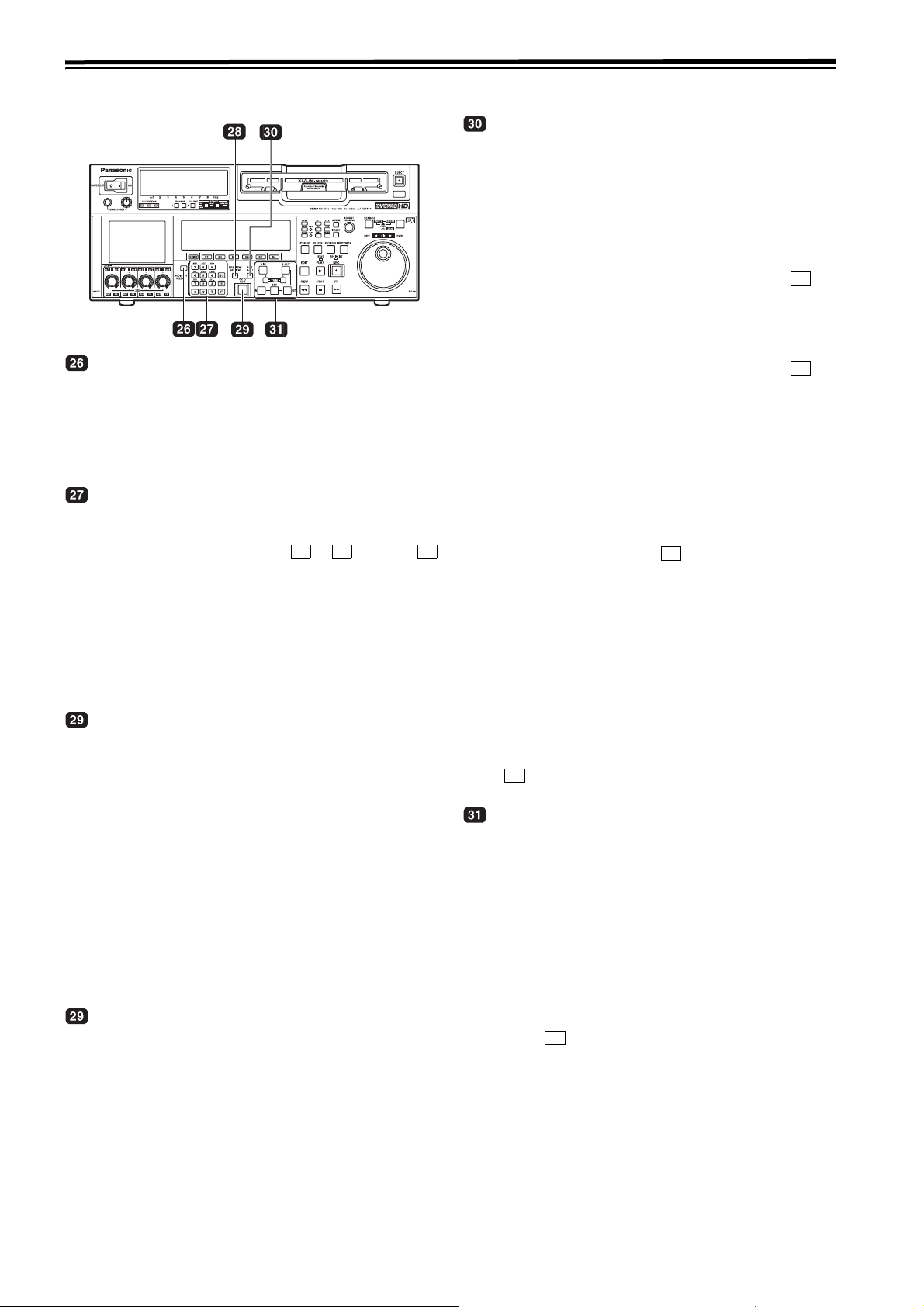
Parts and their functions (continued)
Front panel (3)
Time code display
The data, VTR status information, tape format information
or warning information which corresponds to the direct
menu buttons appear on this display. (See page 38 and
following for details of the displays.)
UNITY lamps
VIDEO UNITY lamp
This lights if all image output levels of the HD/SD
are UNITY.
AUDIO UNITY lamp
This lights if the UNITY level applies for the PCM
or CUE AUDIO input or output level. (The lighting
of the lamp complies with the setting selected for
setup menu item No.142 (AUDIO UNITY).)
DIAG: This enables confirmation of information such as
the warning/hour-meter/UMID. On the SHIFT
screen, the error log files can be checked and
deleted.
MENU:
On this menu, it is possible to transfer operation
to the screen on which operations (adjustments
and saving data in or loading it from the internal
memory and SD memory card) relating to the
SYSTEM and SETUP menus are to be
performed.
See page 38 and following for further details on each of
the function menus.
ASSEM button
This button is used to perform assemble editing.
When it is pressed, the <ASSEMBLE> menu appears on
the time code display. Setting ASSEM to ON using
enables assemble editing, and the lamp of the ASSEM
button lights.
Even after operation is transferred by another direct
menu, the assemble mode will remain established while
the ASSEM button lamp is lighted.
Press the [F1] button when the <ASSEMBLE> menu is
displayed to turn OFF the ASSEM item on the screen.
The ASSEM button lamp now goes off and the assemble
mode is released
F1
Direct menu buttons
These buttons are used to switch directly to the function
menus on the time code display.
HOME:
The most basic settings of recording, playback
and time code operations are selected on this
menu.
VIDEO:
The basic input and output settings for the video
signals are selected on this menu. The level of
the HD output signals can also be adjusted on
this screen.
AUDIO:
The basic input and output settings for the audio
signals are selected on this menu.
PF1: This enables user-defined menu items to be
registered in the function keys.
PF2: This enables user-defined menu items to be
registered in the function keys.
TC: The settings related to the time code are selected
on this menu. Superimposing the time code on
the display can also be set on this screen.
CUE: This enables up to 60 cue points to be set. In the
PAGE mode, 10 pages with 6 cue points on each
page are provided so that the cue points can be
managed on a page-by-page basis.
INSERT button
This button is used to perform insert editing.When it is
pressed, the <INSERT> menu appears on the time code
display, and the function menu for selecting the signals to
be edited is displayed.
To select the signals to be edited, press the function key,
and highlight the display. The highlighted display
indicates that those signals are selected.
To release the selection, press the same function key
again.
F1 F6
Use to to select the V, A1, A2, A3, A4 and CUE
signals; use + to to select the A5, A6, A7,
A8 and TC signals.
SHIFT
F2 F6
ADJUST dial (ADJ dial)
This is used for the menu and other operations.
12
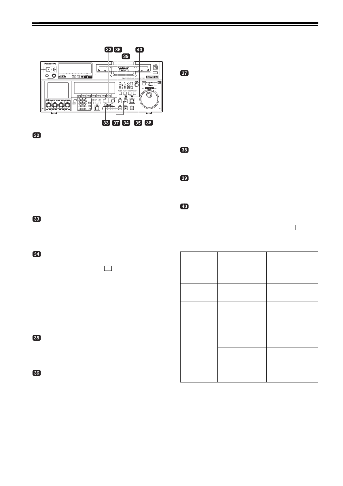
Parts and their functions (continued)
Front panel (4)
Search button
Press this button to shift to the search mode. Set the
search dial to the shuttle mode and turn to any position,
and then press this button to start playback at the rate set
with the search dial.
SHTL/SLOW button
This is the button to select SHTL or SLOW for the search
dial. Every time this button is pressed, the search dial
shifts alternately between the SHTL and SLOW modes.
Search dial
This is the dial to search the edit point. The mode shifts
alternately between SHTL/SLOW and JOG each time the
dial is pressed, and the lamp for either JOG, SHTL, or
SLOW lights. When the power is turned on, the unit
operates once the dial returns to the STILL position.
SHTL (shuttle) mode:
While the lamp is lit for SHTL of JOG/SHTL/
SLOW, turn the dial and stop at any position to
play back images at the rate indicated by the
position of the dial. When the dial is at the center
position, images become still pictures.
SLOW mode:
While the lamp is lit for SLOW of JOG/SHTL/
SLOW, turn the dial all the way to the left to play
back images at a rate 4.9 times slower than the
standard rate. When the dial is at the center
position, images become still pictures. Turn the
dial all the way to the right to play back images at
a rate 4.9 times faster than the standard rate.
SLOW speed can be selected in SETUP MENU
No. 308 (VAR FWD MAX) and No. 309 (VAR
MAX). The rate at the click point can be selected
in the SETUP MENU No. 313 (CLICK POINT).
JOG mode:
In this mode, there are no clicks when turning the
dial. Playback speed is determined by how far the
dial is turned. The maximum rate can be selected
in SETUP MENU No. 310 (JOG FWD MAX) and
No. 311 (JOG REV MAX)
JOG/SHTL/SLOW lamp
This lamp indicates the search dial mode.
JOG:
This lamp lights in JOG mode.
SHTL/SLOW:
This lamp lights in SHTL/SLOW mode.
REV
REV, STILL and FWD lamps
These lamps light to reflect the way in which the search
dial is operated.
REV
: This lights when the dial is turned
counterclockwise, and the tape runs in the REV
direction while the search button lamp is lighted.
STILL: While the JOG lamp is lighted, this lights when
the dial rotation is stopped, and the tape also
stops running.
While the SHTL/SLOW lamp is lit, it lights when
the dial is at the still-picture position.
FWD: This lights when the dial is turned clockwise, and
the tape runs in the FWD direction while the
search button lamp is lighted.
Audio input and output level control dials
These are used to adjust the recording or playback levels
of the CH1, CH2, CH3, CH4, CH5, CH6, CH7 and CH8
PCM audio signals.
z Switching between the LOCK or UNLOCK status for the
volume level operations
When a dial is pressed, the LED above the dial either
lights (LOCK) or goes off (UNLOCK).
In the LOCK (lighted) status, only the display segments
corresponding to the current audio level light, and the
audio level remains unchanged even when the dial is
turned.
In the UNLOCK (off) status, the display segments corresponding to the current audio level and all the display
segments below light, and the audio level can be
changed.
z Switching between UNITY or VAR
UNITY or VAR can be selected when the dial knob is
pressed while holding down the key among the
number keys in the UNLOCK status. The position of
the segment lighted at the center indicates the UNITY
level.
z Switching between REC or PB
The AUTO, REC or PB volume level function can be
selected using of “AUDIO SHIFT2” on the AUDIO
function menu.
With AUTO, the recording controls are automatically
selected during recording or in the EE or INPUT
CHECK status, and the playback controls are automatically selected during playback.
z Switching between CH1jCH4 and CH5jCH8
F1
The audio channel selector button is used to
switch between these two sets of channels.
<Notes>
z The CUE audio input/output level is adjusted in
SETUP MENU No. 790 (CUE REC VOL) and No. 791
(CUE PB VOL).
z While the input is 1394, the audio input level cannot
be adjusted.
F
13
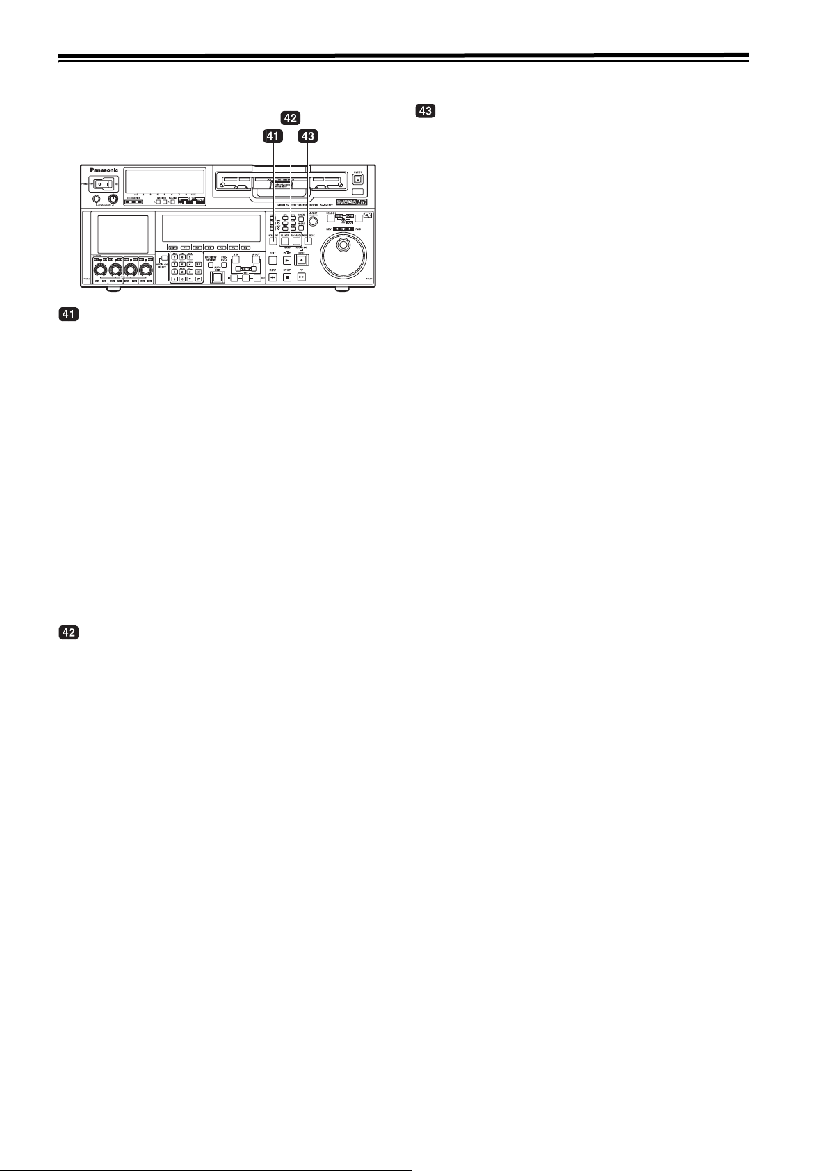
Parts and their functions (continued)
Front panel (5)
Audio channel selector button
Use this button to select whether the audio controls for
channels CH1 to CH4 or for channels CH5 to CH8 are to
be controlled.
Each time it is pressed, the channel display LED above
the audio control is selected.
Number keys
Use these keys to input the numerical values of the CUE
points, edit points, etc.
By pressing a number keys from to while the
key is held down, alphabet letters from A to F which are
used for the user bits or letters from A to Z which are used
to compose filenames can be input.
Since a multiple number of letters are allocated to each
number key, keep tapping the number key until the
desired letter is selected. To change the input position,
use the ADJUST dial, and then proceed with the input.
PREVIEW/REVIEW button
PREVIEW:
When the button is pressed after an edit point has
been registered, the tape travels and the editing
can be previewed without actually performing the
editing.
If the button is pressed when the IN point has not
been registered, the point where it was pressed is
registered as the IN point, and preview is
executed using this IN point.
REVIEW:
When the button is pressed after a section has
been edited, the just edited section is played
back, and it can be reviewed on the recorder’s
monitor.
AUTO EDIT button
When this button is pressed after the edit points have
been registered, automatic editing is initiated.
If the button is pressed when the IN point has not been
registered, automatic editing is initiated with the point
where the button was pressed serving as the IN point.
1 9 F
PREROLL button
This button is used to locate where a transmission or
manual editing starts on the tape.
When it is pressed, the tape travels to the preroll point
and it stops there.
When the cue time has been registered on the HOME,
PF1 or PF2 screen:
The tape is prerolled from the registered cue time
using the preroll time which was set using
(PREROL) on the <HOME SHIFT> menu.
When the search mode is established on the CUE
screen:
The tape is prerolled from the selected cue point
using the preroll time which was set using
(CU-ROL) on the <CUE SHIFT> menu.
The preroll operation is not performed when the
selected cue point has not been registered or
when the cue point registration mode is
established.
In all other situations:
The tape is prerolled from the registered IN point
(or the current tape position when the IN point
has not been registered) using the preroll time
which was set using [ (PREROL) on the
<HOME SHIFT> menu.
If the PREROLL button is pressed when the IN
point has not been registered, the current tape
position is automatically registered as the IN point
[but only when ENA has been selected as the
setup menu item No.305 (AUTO ENTRY) setting].
When the PREROLL button is pressed together with the
IN (A IN) or OUT (A OUT) button, the tape can be cued
up to the registered point concerned. To cue up the tape
for the cue time registered on the HOME, PF1 or PF2
screen, press the PREROLL button while holding down
F
the key among the number keys.
F1
F1
F5
IN (A IN), SET and OUT (A OUT) buttons
When the IN (A IN) or OUT (A OUT) button is pressed
together with the SET button, the IN (A IN) or OUT (A
OUT) point is registered.The A IN and A OUT buttons are
used to register audio IN and OUT points that differ from
the corresponding video points during audio split editing.
When an IN (A IN) or OUT (A OUT) point has been
registered, the lamp of the IN (A IN) or OUT (A OUT)
button which has registered that point lights. When these
buttons are pressed after points have been registered,
the IN (A IN) or OUT (A OUT) point value appears on the
counter display.
When the button is pressed while holding down the IN
(A IN) or OUT (A OUT) button, the registration of the IN (A
IN) or OUT (A OUT) point is cleared.
C
14
Parts and their functions (continued)
Front panel (6)
TRIM buttons
These buttons are used to make fine adjustments to the
IN or OUT point.
By pressing the or j button while the IN (A IN) button or
OUT (A OUT) button is held down, the registered edit
point can be adjusted in 1-frame increments. When the i
button is pressed, the point is moved ahead by one frame;
conversely, when the j button is pressed, it is moved
back by one frame.
The playback phase can be adjusted by pressing the i or
j button while holding down the PLAY button.
REW button
When this button is pressed, the tape is rewound.
The rewinding speed can be selected using setup menu
item No.102 (FF.REW MAX).
<Note>
No guarantees are made for the sound played back in the
search mode.
PLAY button
Press this button to start playback.
When this button is pressed together with the REC
button, recording starts; when this button is pressed
together with the EDIT button during playback, manual
editing starts.
However, manual editing will not be initiated if the servo is
not locked.When only the PLAY button is pressed during
manual editing, editing is exited, and the playback mode
is established.
REC button
When this button is pressed together with the PLAY
button, recording starts.
SERVO lamp
This lamp lights when the drum servo or capstan servo
locks.
REC INHIBIT lamp
This lights or goes off in accordance with the status of the
accidental erasure prevention tab on the cassette tape
and the setting which has been selected for REC INH
on the <HOME> menu. Recording onto the tape is
inhibited while the lamp is lighted.
F6
STOP button
When this button is pressed, the tape stops traveling, and
if TAPE is selected as the OUTPUT setting on the
F1
<HOME> menu, still pictures can be monitored.
Even in the stop mode, the drum continues to rotate, and
the tape remains tightly wound around the drum.
Therefore, when the VTR is left in the stop mode beyond
a specific period of time, it is automatically set to the
standby OFF mode in order to protect the tape. The VTR
is set to the stop mode immediately after the cassette has
been installed.
FF button
When this button is pressed, the tape is fast forwarded.
The fast forwarding speed can be selected using setup
menu item No.102 (FF.REW MAX).
EDIT button
This button is pressed together with the PLAY button
during playback to initiate manual editing.
When the button is pressed in the stop mode, the input
signals in the mode selected by the <ASSEMBLE> menu
or <INSERT> menu can be monitored in the EE mode.
When the STOP button is pressed, the original picture
and sound are restored.
During playback, search, fast forwarding or rewinding, the
input signals in the mode selected by the <ASSEMBLE>
menu or <INSERT> menu can be monitored in the EE
mode while the button is held down.
Cassette tape’s
accidental
erasure
prevention tab
status
Recording
disabled
Recording
enabled
*
Whether the REC INHIBIT lamp is to light or blink is selected by
the No.114 REC INH LAMP setup menu item setting.
REC INH
menu
setting
ー
OFF Off
ALL Lighted
PRE
NORM
V/CTL
REC
INHIBIT
lamp
status
Lighted*
(or blinks
slowly).
Blinks
rapidly
Blinks
rapidly
Blinks
rapidly
Description of
operation
All recording operations
are inhibited.
All recording operations
are permitted.
All recording operations
are inhibited.
Recording operations
involving the overwriting
of existing material are
inhibited.
Normal recording
operations are inhibited.
Editing is possible.
Recording of video
signals and CTL signals
are inhibited.
<Note>
When SETUP MENU No. 18 (SP MODE INH) is set to
ON, data cannot be recorded onto a tape that was
formatted in any other format than DVCPRO HD-LP. If the
menu is set to OFF, data can be recorded.
15
Parts and their functions (continued)
Front panel (7)
STANDBY button
While the head drum is rotating, the button’s lamp lights
to indicate that the standby ON mode is now established.
The same tape tension is applied as in the regular stop
mode.
If the button is pressed in the stop mode, the standby
OFF mode is established followed by the half loading
mode. At this time, its lamp goes off.
When the VTR is left in the stop mode beyond a specific
period of time, it is automatically set to the standby OFF
mode in order to protect the tape.
In the standby OFF mode, if this button or the STOP
button is pressed, the VTR is set to the standby ON
mode. If a button other than the STOP button is pressed,
the VTR is set to the mode that corresponds to the button
pressed.
The time taken by the VTR to transfer to the standby OFF
mode can be selected using a setup menu item.
INPUT CHECK button
Only while this button is held down are the input signals
from the monitor output connector output to enable the
input video and audio signals to be monitored.
The time code generator can be checked on the time
code display.
Select LATCH as the setup menu item No.517 (TCG
OUT) setting in order to continue displaying the time code
generator value even after the INPUT CHECK button has
been released.
<Notes>
z
The INPUT CHECK function does not work for the
CUE signal. Input signals can be monitored in the EE
mode.
z The monitor operation varies with the VIDEO/AUDIO
input selection. For details, refer to the INPUT
CHECK output specifications on pages 17 and 18.
PLAYER and RECORDER buttons
These buttons are operated if the VTR is to be used as a
recorder to conduct editing operations with a VTR
equipped with an RS-422A serial interface remote control
connector (9 pins). Neither button works when the VTR is
used on its own.
PLAYER:
When this button is pressed, its lamp lights to
indicate that the player connected to the VTR can
be operated by remote control. The VTR’s editing
and tape transport system buttons can now be
used to control the player.
RECORDER:
When this button is pressed, its lamp lights to
indicate that the editing and tape transport
system buttons can now be used to operate the
recorder (this VTR).
z
When the PLAYER button or RECORDER button is
pressed while ENA has been selected as the setup
menu item No.200 (PARA RUN) setting, the lamps of
both buttons light to indicate that the VTR now serves
as the master unit for parallel run operations.
However, when this setting is used, it is no longer
possible to perform external control from the
REMOTE connector (9 pins).
16

Parts and their functions (continued)
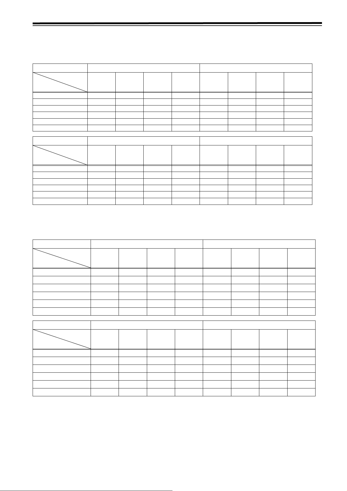
Front panel (8)
INPUT CHECK output specifications
VIDEO
Input selection
(MENU 600)
INT SG HD SDI SD SDI 1394
Output system
HD SDI
(MONITOR)
SD SDI
(MONITOR)
LCD
(MONITOR)
VIDEO OUT3
* Only output from the internal signal processing circuit is delayed.
INT SG* HD SDI
INT SG*
INT SG* HD SDI* SD SDI 1394*
INT SG* HD SDI* SD SDI* 1394*
MUTE
(BLACK)
<Notes>
z Signals for INT SG input are selected in Menu No. 601.
z INPUT CHECK is disabled when 23/24 Hz mode or 25 Hz
(HD, SD) mode and 50 Hz (HD, SD) mode are selected.
z INPUT CHECK is disabled during tape playback when INT
SG or 1394 is selected.
z INPUT CHECK is disabled in VIDEO OUT3. It returns to
the normal output state.
MUTE
(BLACK)
SD SDI 1394*
1394*
17
Parts and their functions (continued)
INPUT CHECK output specifications (continued)
AUDIO (EE mode)
MONITOR L/R and HEAD PHONE L/R interlock with the MONITOR SELECT button on the front panel.
AUDIO Input selection INT SG SDI
VIDEO Input
Output system
selection
HD SDI (MONITOR)
SD SDI (MONITOR)
MONITOR L
MONITOR R
HEAD PHONE L
HEAD PHONE R
AUDIO Input selection AES/EBU ANALOG
VIDEO Input
selection
Output system
HD SDI (MONITOR)
SD SDI (MONITOR)
MONITOR L
MONITOR R
HEAD PHONE L
HEAD PHONE R
INT SG HD SDI SD SDI 1394 INT SG HD SDI SD SDI 1394
INT SG* INT SG* MUTE 1394* HD SDI* HD SDI* MUTE 1394*
INT SG* MUTE INT SG* 1394* HD SDI* MUTE SD SDI* 1394*
INT SG* INT SG* INT SG* 1394* HD SDI* HD SDI* SD SDI* 1394*
INT SG INT SG INT SG* 1394* HD SDI* HD SDI* SD SDI* 1394*
INT SG* INT SG* INT SG* 1394* HD SDI* HD SDI* SD SDI* 1394*
INT SG* INT SG* INT SG* 1394* HD SDI* HD SDI* SD SDI* 1394*
INT SG HD SDI SD SDI 1394 INT SG HD SDI SD SDI 1394
AES/EBU* AES/EBU* MUTE 1394* ANALOG* ANALOG* MUTE 1394*
AES/EBU* MUTE AES/EBU* 1394* ANALOG* MUTE ANALOG* 1394*
AES/EBU* AES/EBU* AES/EBU* 1394* ANALOG* ANALOG* ANALOG* 1394*
AES/EBU* AES/EBU* AES/EBU* 1394* ANALOG* ANALOG* ANALOG* 1394*
AES/EBU* AES/EBU* AES/EBU* 1394* ANALOG* ANALOG* ANALOG* 1394*
AES/EBU* AES/EBU* AES/EBU* 1394* ANALOG* ANALOG* ANALOG* 1394*
* Only output from the internal signal processing circuit is delayed.
AUDIO (Tape mode)
MONITOR L/R and HEAD PHONE L/R interlock with the MONITOR SELECT button on the front panel.
AUDIO Input selection INT SG SDI
VIDEO Input
Output system
selection
HD SDI (MONITOR)
SD SDI (MONITOR)
MONITOR L
MONITOR R
HEAD PHONE L
HEAD PHONE R
AUDIO Input selection AES/EBU ANALOG
VIDEO Input
selection
Output system
HD SDI (MONITOR)
SD SDI (MONITOR)
MONITOR L
MONITOR R
HEAD PHONE L
HEAD PHONE R
INT SG HD SDI SD SDI 1394 INT SG HD SDI SD SDI 1394
INT SG*
INT SG*
1
1
INT SG*1INT SG*1INT SG*
INT SG*1INT SG*1INT SG*
INT SG*1INT SG*1INT SG*
INT SG*1INT SG*1INT SG*
TAPE*
MUTE
2
MUTE
2
TAPE*
1
1
1
1
1394*
1394*
1394*
1394*
1394*
1394*
1
HD SDI*
1
HD SDI*
1
HD SDI*1HD SDI*1SD SDI*
1
HD SDI*1HD SDI*1SD SDI*
1
HD SDI*1HD SDI*1SD SDI*
1
HD SDI*1HD SDI*1SD SDI*
1
TAPE*
1
MUTE
2
TA PE *
INT SG HD SDI SD SDI 1394 INT SG HD SDI SD SDI 1394
AES/EBU*1TAPE*
1
AES/EBU*
MUTE
2
MUTE
2
TAPE*
1
1394*
ANALOG*1TAPE*
1394*1ANALOG*
2
1
MUTE
TA PE *
AES/EBU*1AES/EBU*1AES/EBU*11394*1ANALOG*1ANALOG*1ANALOG*11394*
AES/EBU*1AES/EBU*1AES/EBU*11394*1ANALOG*1ANALOG*1ANALOG*11394*
AES/EBU*1AES/EBU*1AES/EBU*11394*1ANALOG*1ANALOG*1ANALOG*11394*
AES/EBU*1AES/EBU*1AES/EBU*11394*1ANALOG*1ANALOG*1ANALOG*11394*
MUTE
MUTE
1
1394*
2
1
1
1
1
2
1394*
1394*
1394*
1394*
1394*
1394*
1394*
1
1
1
1
1
1
1
1
1
1
1
*1 Only output from the internal signal processing circuit is delayed.
*2 The playback sounds from the same tape as the main line system are output.
<Notes>
z Noise may occur if VIDEO INPUT does not synchronize with OUTREF.
z Signals at the time when INT SG input is selected can be selected in Menu No. 761.
z INPUT CHECK is disabled while playing back a tape when INT SG or 1394 is selected.
18
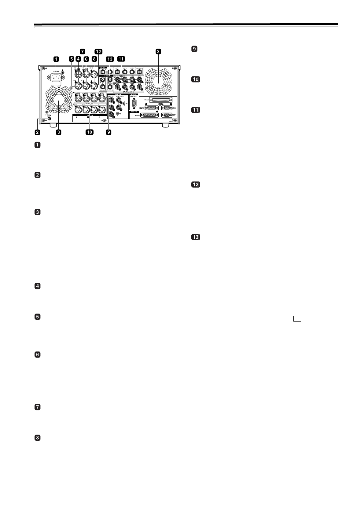
Parts and their functions (continued)
Rear panel
AC IN socket
Using the power cord supplied, connect one end to this
socket and the other end to the power outlet.
SIGNAL GND terminal
This is connected to the signal ground terminal on the
component connected to this VTR in order to minimize
noise. It is not a safety ground.
Fan
The fan is used to cool down the VTR.
When the fan stops due to an abnormal condition, the
warning symbol (W) is displayed on the time code display
section and a warning beep is sounded.
If the VTR is made to continue operating in the warning
status, the temperature inside the deck rises, and when it
exceeds the safety temperature, all the VTR’s operations
will be shut down.
TIME CODE IN connector
This connector is used to record an external time code
onto the tape.
TIME CODE OUT connector
During playback, the playback time code is output through
this connector. During recording, the time code
generated by the internal time code generator is output.
CUE IN connector
The analog signals to be recorded on the CUE tracks are
input through this connector.
Audio signals from a microphone can also be recorded by
selecting the j60 dB input mode for setup menu item
No.704 (CUE IN LV).
CUE OUT connector
The analog signals recorded on the CUE tracks are
output through this connector.
ANALOG AUDIO IN connectors
These are the analog audio input connectors (for CH1,
CH2, CH3 and CH4).
ANALOG AUDIO OUT connectors
These are the analog audio output connectors (for CH1,
CH2, CH3 and CH4).
HD SERIAL DIGITAL COMPONENT AUDIO
VIDEO IN/OUT connector/ACTIVE THRU
The HD digital component audio and video signals
complying with the SMPTE 292M, 296M and 299M
standards are input and output through this connector.
Signals with the time code, menu or other superimposed
information are output from the HD SDI MONITOR.
For INPUT CHECK, refer to the INPUT CHECK output
table on pages 17 and 18.
SD SERIAL DIGITAL COMPONENT AUDIO
VIDEO IN connector/ACTIVE THRU
This is an input connector for SD SDI signals that comply
with the SMPTE 259M-C, 272M-A, or ITU-R BT.656-4
standards. The SD SDI input acts as an up converter and
records data.
SD SERIAL DIGITAL COMPONENT AUDIO
and VIDEO OUT connectors
The digital component audio and video signals complying with
the SMPTE 259M-C or 272M-A standard are output from
these connectors. Video signals are output during
DVCPRO50M/25M/DV/DVCAM compatible playback and
down-converting output. Video images are output from the SD
SDI MONITOR together with supers such as the TC/Menu.
Using setup menu item No.606 (SD MONI O SEL), it is also
possible to make the SD SDI MONITOR output the same
output as SD SDI OUT1 (no information superimposed).
When “SD SDI” has been selected as the (VID IN) setting
on the <VIDEO> menu and “THRU” has been selected as the
No.107 (EE MODE SEL) setting, no information is
superimposed onto the SD SDI MONITOR output signals in
the EE mode, and the same output as SD SDI OUT1 is
delivered.
z For INPUT CHECK, refer to the INPUT CHECK
output table
are muted during cross conversion.
<Note>
In the 23/24 Hz mode, the system phase of the SD SDI
output and analog composite video output is subject to
change when the tape has been set to travel at the
normal speed (1k) so that the HD SDI output and phase
will be aligned.
on pages 17 and 18. Note that the signals
F1
MONITOR OUT connectors
The CH1, CH2, CH3, CH4, CH5, CH6, CH7 and CH8
PCM audio signals or CUE signals are output through
these connectors.
19
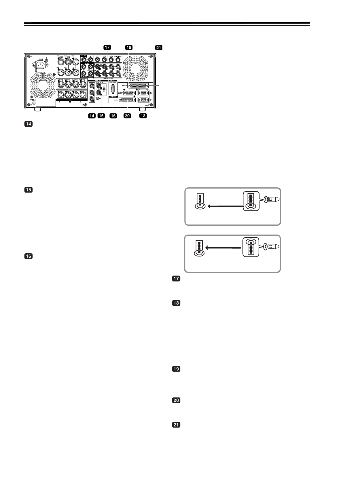
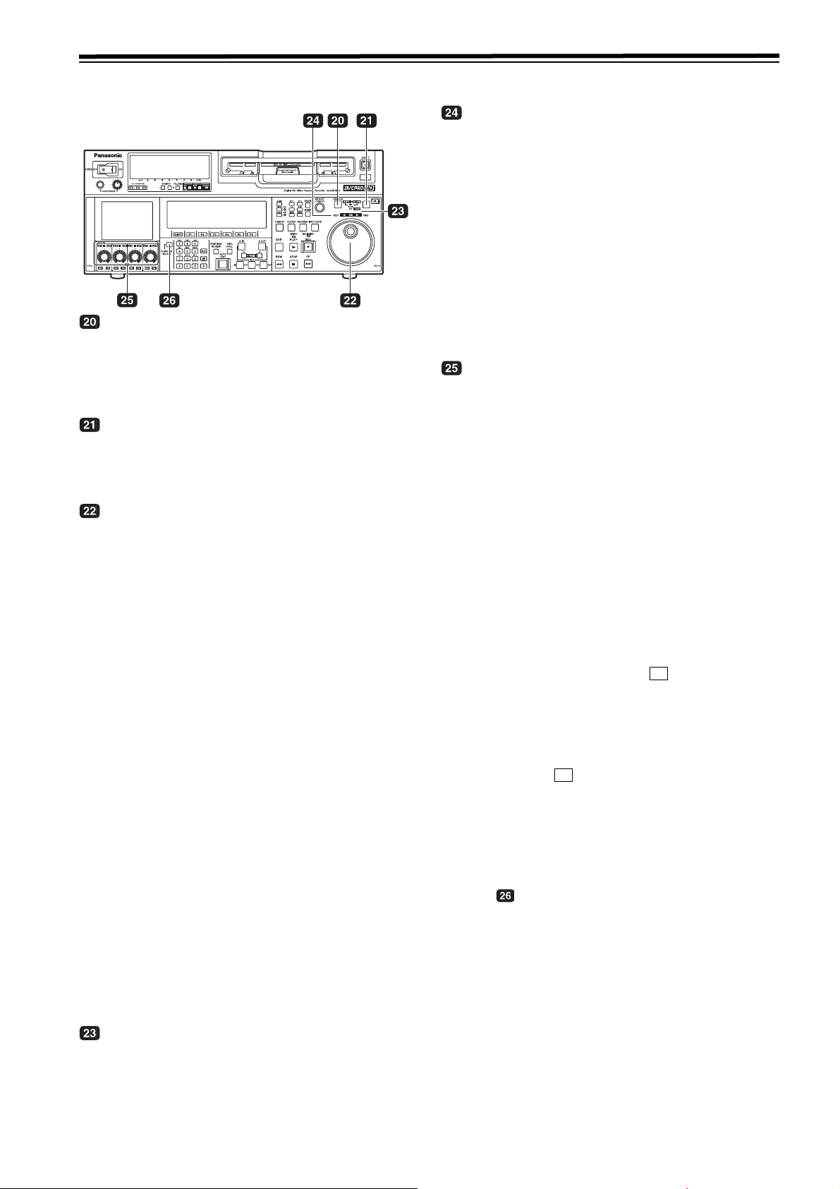
Parts and their functions (continued)
Rear panel (continued)
ANALOG COMPOSITE VIDEO OUT connectors
The analog composite video signals are output through
these connectors. They are output during DVCPRO50M,
25M, DV or DVCAM interchangeable playback or when
signals are down-converted and output.
Video signals containing superimposed information can
be output through the VIDEO OUT 3 connector. Whether
the superimposing is to be set ON or OFF is selected
using the setup menu item No.005 (SUPER).
H
D/SD REF IN connector and 75 h terminal switch
These are the input connectors for the HD/SD reference
video signals and the loop-through output connector. To
terminate signals, turn the switch [ON].
<Notes>
z To use the connector as the HD reference, input the positive-
negative bipolar three-value synchronization signal. Input
signals that conform to the input signal or the tape format.
z To use the connector as the SD reference, input black burst
signals must comply with SMPTE170M and ITU624-4.
IEEE1394 digital input/output
The IEEE1394 digital interface is available for input and output.
Use a 6-pin type connector. Bus power is not supported.
<Notes>
z Ensure that the connections with other devices are made on
a 1:1 basis.
z When an IEEE1394 cable has been connected to the
IEEE1394 digital input/output connector, do not apply any
strong external force as this may damage the connector.
z
When error code E-92 (1394 INITIAL ERROR) appears,
disconnect the connecting cables and re-connect them or turn
off the unit’s power and turn it back on.
z The AV signals may be disrupted when the power of the
connected devices is turned on or off and when the 1394
cable is connected or disconnected.
z When the input signals are switched or the mode is
transferred, it may take a few seconds for the system to
stabilize. Proceed with the recording operation only after the
system has stabilized.
z The following situation applies when recording is to be
performed by selecting the IEEE1394 digital interface input,
and it applies with the signals which are output by the
IEEE1394 digital interface.
When playback signals other than regular 1a speed
playback signals have been input, no guarantees are made
for the pictures and sound which will be recorded or for the
EE-type pictures and sound.
z
The following situation applies when the video input
selection has been set as the IEEE1394 digital interface.
The SDI signals, the analog video output signals and time
code output signals become irregular in the EE mode. Do
not use these signals for recording purposes. (The teletext
signals and other signals superimposed onto the video
output signals also become irregular.)
z During SLOW/STILL playback, unprocessed video and
audio signals are output as the IEEE1394 digital interface
output. When these video and audio signals are monitored
using another device, they may differ from the video and
audio signals played back by this unit. When the equipment
for non-linear editing is connected to this unit, do not start
any other application program than software for the nonlinear edit. Non-linear editing equipment may garble the
output video picture.
Be absolutely sure to bear the following points in mind
when connecting the IEEE1394 cable.
z Ensure that the unit and all of the connected devices are
each grounded (or connected to a common ground) before
use. If it is not possible to ground the unit and devices, turn
off the power of the unit and of all the connected devices
before connecting or disconnecting the IEEE1394 cable.
z When the unit is to be connected to a device equipped with a
4-pin type of connector, connect the unit’s connector (6-pin
type) first.
z When connecting the unit with a PC equipped with a 6-pin
type of connector, connect the 1394 cable as dictated by the
shapes of the IEEE1394 connectors. Bear in mind that
inserting a plug the wrong way round may damage the unit.
Right
IEEE1394
connector
END of IEEE1394
cable
Wrong
IEEE1394
connector
END of IEEE1394
cable
DIGITAL AUDIO IN and OUT connectors
These are the input and output connectors of the digital
audio signals that comply with the AES/EBU standards.
Remote control connectors
The unit can be operated externally by connecting two
units or an external controller to one unit.
Two remote control connectors are provided: one for IN/
OUT uses and the other for OUT uses only.
IN/OUT:
For connection with an external controller
For connection during deck-to-deck operations
OUT: For connection during parallel run operations
For loop-through uses
ENCODER REMOTE connector
An external encoder remote controller is connected to this
connector when the video output signal settings are to be
adjusted from an external component.
RS-232C connector
Data communication is available by connecting the unit to
a personal computer.
PARALLEL REMOTE connector
The unit can be operated externally with the 50-pin
parallel remote.
20
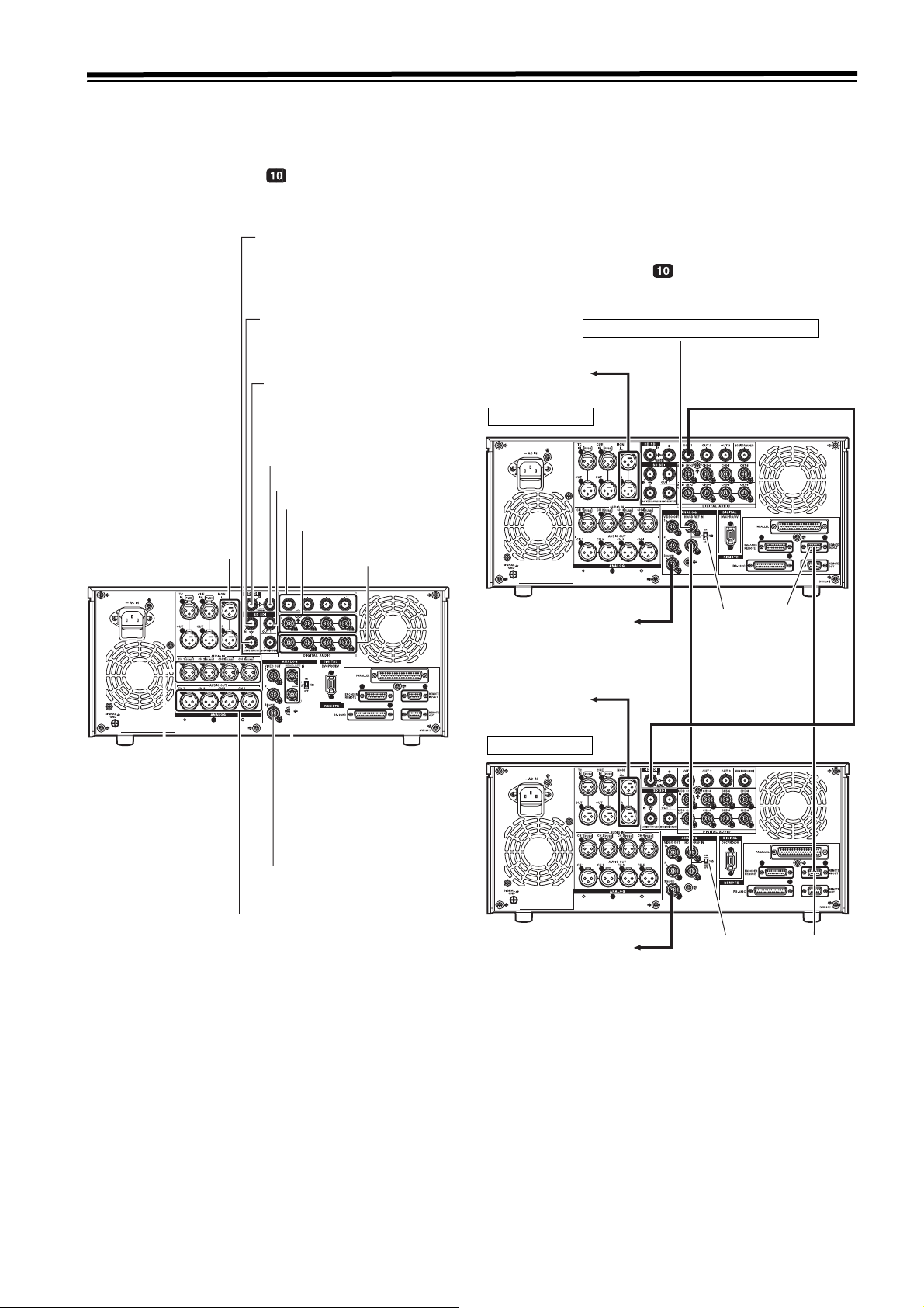
Connections
Example of connections performed for one VTR
Set the REMOTE LED on the front panel to the
off status (LOCAL mode).
SD SDI input ACTIVE THRU
SD SDI input
(audio, video)
HD SDI input
(audio, video)
HD SDI output
(ACTIVE THRU)
SD SDI output
HD SDI outputs
Digital audio inputs
Audio monitor outputs
Digital audio outputs
Example of connections performed for two VTRs (deck-to-deck)
Source side:
Press the “9P 1394” REMOTE button on the front panel
for 2 or more seconds to set the VTR to the REMOTE
status. (The LED lights.)
Recorder side:
Set the REMOTE LED on the front panel to the off
status (LOCAL mode).
SD reference signal generator
To audio monitor
component
HD SDI signal
Source side
Video monitor output
(3 composite output lines)
Analog audio outputs
Analog audio inputs
HD/SD reference inputs
(loop-through output)
To video monitor
component
To audio monitor
component
Recorder side
To video monitor
component
75
h
termination
OFF
75
h
termination
ON
REMOTE
IN/OUT
Remote
signal (9P)
REMOTE
IN/OUT
21
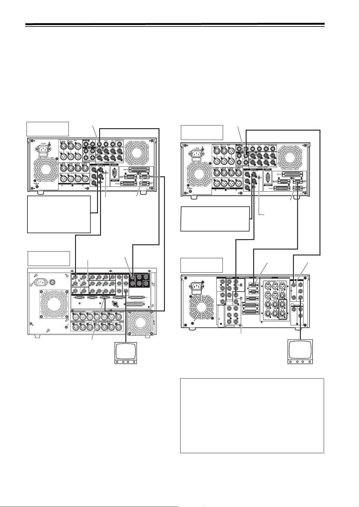
Connections (continued)
Example of connections in 23/24 Hz or 25/ 50 Hz (HD) mode
When a tape recorded with a frame rate of 24 fps (25/50 fps)
using a variable frame rate camera is played back on the
unit, data can be converted and output in 1080/24 psf (1080/
25 psf or 1080/50i) and recorded on the AJ-HD3700 series.
Shown in the figure below is an example of the deck-to-deck
connections.
Input the 48 Hz (or 50 Hz) reference signal as the REF input.
AJ-HD1800
(Source side)
Reference signal
For 24 Hz mode:
HD REF 48 Hz (Interlace)
For 25 Hz (HD)/50 Hz (HD) mode:
HD REF 50 Hz (Interlace) or
SD REF 50 Hz (Interlace)
AJ-HD3700B
(Recorder side)
~
AC IN
FUSE
125V 5A
HD SDI OUT
75h
termination
ON
123
SD
HD
ON
ON
75g
75g
CH CH CH CH
OFF
OFF
SD
SD
HD
CH CH CH CH
REF OUT DIGITAL AUDIO
REMOTE
IN
AUDIO IN
CH 1 CH 2 CH 3 CH 4 CH 5
AUDIO OUT
CH 1 CH 2 CH 3 CH 4
PUSHPUSHPUSHPUSHPUSHPUSHPUSH
SIGNAL
GND
75h
termination
OFF
HD SDI IN
(
)
SUPER
INPUT
OUTPUT
REMOTE
REMOTE
OUT
IN/OUT
CONTROL
PANEL
CUE L R
HD SDI signal
IN
OUT1
ACTIVE
THROUGH
OUT2
MONITOR
SPARE
(
)
SUPER
V/A
CONTROL
TIME CODE
IN
OUT
PUSH
MONITOR
REMOTE
IN/OUT
Remote
signal (9P)
HD SDISD SDIWFMVIDEO OUTREF IN
IN
OUT
OUT
1
ACTIVE
THROUGH
OUT
2
3
MONITOR
(
)
SUPER
RS-232C
PARALLEL
IN/OUT
(
)
50P
Example of connections in 25/50 Hz (SD) mode
When a tape recorded with a frame rate of 25/50 fps using a
variable frame rate camera is played back on the unit, data
can be converted and output in 576/50i and recorded in the
SD-VTR. An example of a connection between decks is
shown in the following illustration.
Input the 50 Hz reference signal to the SD REF input
connector as the REF input.
SD SDI OUT
AJ-HD1800
(Source side)
Reference signal
SD REF 50Hz
(interlace)
AJ-SD965
(Recorder side)
AC IN
SIGNAL
GND
CH1/2
CH3/4
CH1/2
OUT
CH3/4
OUT
IN
IN
AES/EBU
ANALOG
Y
P
B
P
R
OPTION
Y1
2
P
B
(WFM)
3
P
(SUPER)
R
SERVICE ONLY
REMOTE
VIDEO
IN
REMOTE IN/OUT
ON
75?
OFF
REMOTE OUT
REF VIDEO
IN
ENCODER REMOTE
ON
75?
OFF
RS-232C
VIDEO
OUT
PARALLEL
SD SDI signal
REMOTE
IN/OUT
75
h
termination
OFF
Remote
signal
(9P)
REMOTE
IN/OUT
ANALOG
PUSHPUSH
CH1 CH2AUDIO
CH1 CH2AUDIO
IN
IN
PUSHPUSH
CH3
CH3
CH4
CH4
CH1 CH2AUDIO
CH1 CH2AUDIO
OUT
OUT
CH3
CH3
CH4
CH4
SD
SDI IN
SDI
OUT
IN
TC
TC
PUSH
IN
IN
1
ACTIVE
TC
TC
PUSH
THROUGH
OUT
OUT
2
3
(SUPER)
PUSHPUSHPUSH
MON
MON
L
L
OPTION
SDTI
IN OUT
PUSHPUSHPUSH
MON
MON
1
R
R
2
REMOTE
IN/OUT
Video monitor
<Notes>
z When the tape begins to travel at 1k speed, the video
may be disturbed and the audio muted for several frames
in order to synchronize the REF input with the tape.
z VITC signals are not output to the SD SDI and VIDEO
OUT connectors in the 23/24 Hz mode.
z In the 25/50 (HD) Hz mode, the output video signals of the
SD SDI and VIDEO OUT connectors are delayed by
approximately 1 field in relation to the HD SDI output.
z HD SDI output is muted in the 25/50 Hz (SD) mode.
22
h
75
termination
ON
Video monitor
Note concerning tapes played back by this VTR
z Use tapes which have been shot by a variable frame rate
camera.
z Do not use tapes which are copies of shot tapes or
edited tapes. Doing so will cause the tape management
information to be lost, and normal conversion and
playback may not be possible as a result.
z To convert a tape recorded at frame rates other than 24
fps (25/50 fps) into 1080/24 psf (1080/25 psf or 1080/
50i), use the frame rate converter (optional AJ-FRC27).
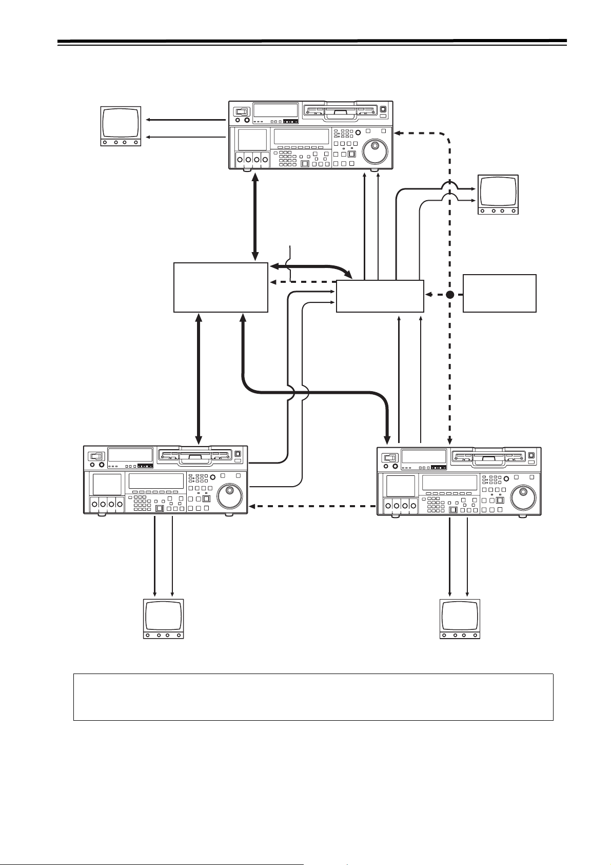
Connections (continued)
Example of connections with an editing controller
AV mo nit or
Video monitor
signals
Audio monitor
signals
Editing controller
Recorder
To REMOTE IN/OUT
Av monitor
Reference signal
Remote signals
Remote signals
Video monitor signals
Audio monitor
Video input signals
Audio input signals
AV switcher
Remote signals
Video output signals
Audio output
signals
signals
Reference signal
generator
Source unit
Video monitor
signals
Av monitor
Remote signals
Audio monitor
signals
To RE MO TE
IN/OUT
Reference signal
To
REMOTE
IN/OUT
Video output signals
Source unit
Audio output signals
Video monitor
signals
Av monitor
Reference signal
Audio monitor
signals
<Note>
When disconnecting the remote signals (9P) from one component and re-connecting them to another component,
check the settings, etc. of the editing controller.
23
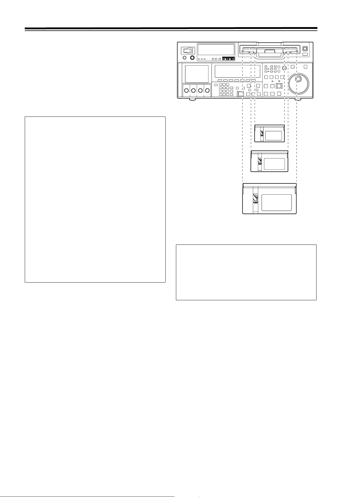
Concerning tapes
Consumer-use DV and DVCAM cassettes
(Standard DV and DVCAM cassettes, mini DV and
DVCAM cassettes)
Use a cassette adapter (AJ-CS455P) when a mini DV or
DVCAM cassette is to be used.
Note that inserting a mini DV or DVCAM cassette without the
use of a cassette adapter will cause malfunctioning.
Also note that long-duration mini DV cassettes (80 minutes
in the standard mode and 120 minutes in the LP mode)
cannot be used.
<Precautions when playing back consumer-use
DV and DVCAM tapes>
z It is not possible to play back consumer-use tapes which
have been recorded in the LP mode.
z The maximum transport speed of a consumer-use DV or
DVCAM cassette tape is 32k.
z The maximum still time for a consumer-use DV or
DVCAM cassette tape is 10 seconds.
z From the perspective of protecting consumer-use DV
and DVCAM cassette tapes, minimize the number of
times the tapes are cued up at the same place as far as
possible.
z When consumer-use DV and DVCAM cassette tapes are
used, the maximum time for STILL TIMER is set to 10
seconds and the total time elapsing when the VTR is left
standing in the STILL mode (When the STEP FWD
mode is selected) is set to 1 minute.
z When editing material which has been recorded onto a
consumer-use DV or DVCAM cassette tape, first record
the material onto a DVCPRO HD tape or another VTR
used for broadcasting applications.
z Noise may occur when performing slow playback using
consumer-use DV or DVCAM cassette tapes.
It is recommended that tapes bearing the Panasonic
brand be used as the consumer-use DV tapes.
M cassette size
L cassette size
XL cassette size
Align the cassette with the center of the insertion slot, and
push it in gently.
The cassette tape will be loaded automatically.
<Notes on cassette insertion>
z Set the cassette level with the cassette slit and insert
straight.
z Do not put your hand in the cassette slit.
z Insert an M/L-cassette between the left/right M/L-
cassette guides.
z If the cassette slit is exposed to the strong direct rays of
the sun, a malfunction in the tape travel may occur.
M cassettes
Tapes capable of up to 33 minutes of recording or playback
(AJ-HP33EMG: for AJ-HD1800E)
L cassettes
Tapes capable of up to 64 minutes of recording or playback
(AJ-HP64ELG)
XL cassettes
Tapes capable of up to 126 minutes of recording and
playback
(AJ-HP126EXG)
24
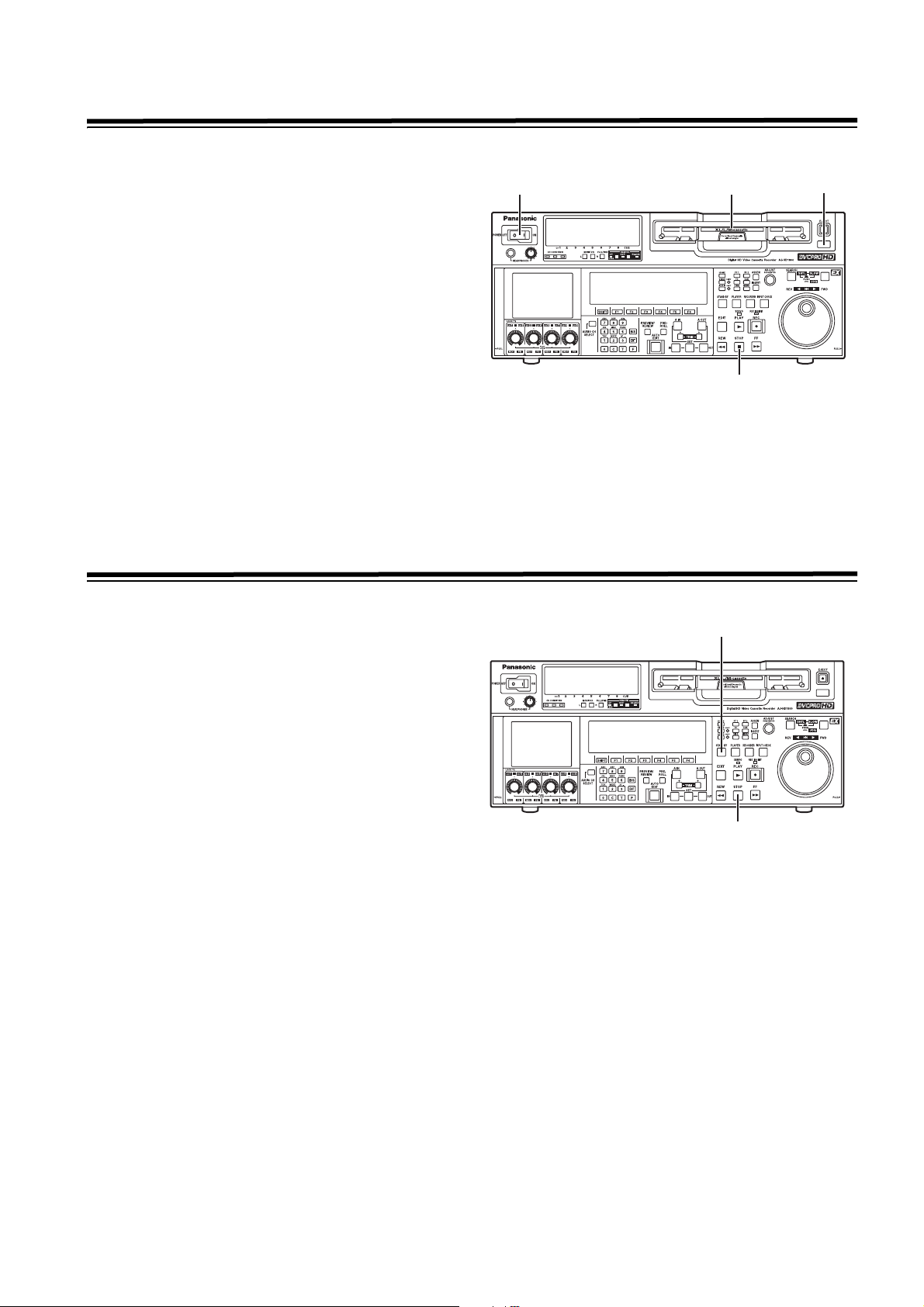
Turning on the power and inserting the cassette
Before starting to operate the VTR, check whether the
equipment has been connected properly.
1
1 Turn on the VTR’s power.
2 Check that the AUTO OFF lamp is off.
If condensation or some other problem has occurred, the
AUTO OFF lamp lights, and no further operations can be
performed.
3 Insert the cassette tape.
Without forcing it, insert the cassette tape at the
prescribed position.
4 Check that the STOP lamp is lighted.
When the tape is inserted, the cylinder starts rotating
automatically, the tape is loaded, and the VTR is set to
the STOP mode. The EJECT lamp goes off.
STOP and STANDBY modes
1 The VTR is set to the STOP mode when its STOP button
is pressed.
The STOP lamp lights, and the tape stops running.
z In order to protect the tape, the VTR is set to standby
OFF after the time set by setup menu item No.400
(STILL TIMER) has elapsed. If the STOP, REW, FF or
PLAY button is now pressed, the VTR will be set to the
corresponding mode.
3
2
4
2
2 The VTR is set to the STANDBY ON/OFF mode when its
STAND BY button is pressed.
The standby ON mode is established while the button’s
lamp is lighted. When the button is pressed in the
standby OFF mode, the VTR is set to the standby ON
mode.
When the button is pressed while the VTR is in the STOP
mode, it is set to the standby OFF mode and the halfloading status, and the button’s lamp goes off.
<Precautions for STILL TIMER setting>
The cumulative total standby time at the same place
increases when programs are transmitted or the same
material is used repeatedly. In order to protect the tape,
keep the standby time at the same place on the tape as
short as possible by, for instance, selecting a maximum of 30
seconds or so as the setup menu item No.400 (STILL
TIMER) setting.
1
25

Recording
1 Set the accidental erasure prevention tab on the cassette
tape to the “REC” position, and insert the tape.
2 Press the STOP button to set the VTR to the stop mode.
3 Select “EE” as the OUTPUT setting using on the
<HOME> menu. EE pictures now appear on the TV
monitor.
F1
4 Check that the REC INHIBIT lamp is off.
If the lamp is lighted, select “OFF” as the R INH setting
F6
using on the <HOME> menu.
If the inserted cassette has been formatted in a format
other than DVCPRO HD-LP, recording is prohibited by
default (factory settings) as set in SETUP MENU No. 118
(SP MODE INH).
5 Select the video and audio input signals, and adjust the
audio levels.
Selecting the video and audio input signals
1 Connect the signals to be recorded.
2 Select the input signals using on the <VIDEO>
menu and to on the <AUDIO> menu or
<AUDIO SHIFT1> menu
F1 F6
Adjust the audio levels
1 Adjust the audio input levels of the CH1, CH2, CH3,
CH4, CH5, CH6, CH7, CH8 audio signals and analog
cue signal selected on the AUDIO menu.
When the audio UNITY lamp on the front panel is
lighted, the audio signals will be recorded at the
appropriate levels.
2 Before adjusting the recording level, check that the
REC LED is lighted and that the audio adjustment dial
is in the unlocked status (LOCK LED off).
If the dial is in the LOCK status (LOCK LED lighted),
press it. The LOCK LED goes off, and the lock is
released.
In addition, the analog cue audio recording level is
adjusted using setup menu item No.790 (CUE REC
VOL) so that it will not exceed j20 dB.
F1
6 Press the PLAY button while holding down the REC but-
ton.
The REC and PLAY lamps light, and recording starts.
7 When the STOP button is pressed, the recording ends,
and the VTR is set to the stop mode.
<Notes>
z During recording, check that the SERVO lamp is lighted.
The playback pictures will be disturbed if it is blinking or
off.
z If analog signals (ANA1 to ANA4) have been selected as
the CH5 to CH8 input signals on the AUDIO menu, their
recording levels are tied in with the recording levels which
have been set for the CH1 to CH4 signals.
z The audio playback level of 1394 output cannot be
adjusted.
26

Playback
1 Insert the cassette tape, and set the VTR to the STOP
mode.
2 Press the PLAY button.
Normal playback commences.
3 Adjust the audio playback levels.
Before adjusting the playback levels, check that the PB
LED is lighted and that the audio adjustment dial is in the
unlocked status. If the dial is locked (indicated by the
lighted LOCK LED), press it. The LOCK LED goes off,
and the lock is released. The analog cue audio level is
adjusted using setup menu item No.791 (CUE PB VOL).
Normally, the VTR is kept in the UNITY status (the
segment display of the control lights at the center).
4 To end the playback, press the STOP button. The VTR is
now set to the STOP mode.
<Notes>
z During playback, check that the SERVO lamp is lighted.
The playback pictures will be disturbed if the lamp is off or
blinking.
z The audio playback level of 1394 output cannot be
adjusted.
Playback phase adjustment function
If two VTRs are to be used to play the same program, the
playback phase between the VTRs can be adjusted by
changing the playback speed of one of the VTRs.
1 Press the TRIM button (“i” or “j” button) while holding
down the PLAY button. Each time it is pressed, the playback speed is accelerated or decelerated in increments
of the number of playback framing fields selected by the
setup menu item No.109 (CAP.LOCK) setting.
The SERVO lamp remains off while the tape is being
played at the accelerated or decelerated speed.
2 Upon completion of the playback phase adjustment,
release the PLAY button.
The VTRs now return to the standard playback speed,
and the SERVO lamp lights.
27

Jog/Shuttle
Jog Mode
1 Push in the search dial.
Confirm that the JOG lamp lights.
2 Turn the search dial.
The dial’s click-stops are released, and the tape is played
back at the speed corresponding to the speed at which
the dial is turned.
The maximum jog speed can be changed by selecting
the setup menu item No.310 (JOG FWD MAX) and
No.311 (JOG REV MAX) settings.
When the dial is no longer turned, a still picture will
appear.
3 To transfer the VTR from the jog mode to another mode,
press the button that corresponds to the mode concerned.
<Note>
The default setting for the search dial is the direct search
mode for moving to the shuttle mode/jog mode/variable
mode.
It is possible to set the mode to the search mode only when
the search button is pressed by changing the setting in
SETUP MENU No. 100 (SEARCH ENA) to [KEY].
Shuttle Mode
1 Press the search dial to return the pressed dial to the
original position.
The SHTL lamp lights, and the mode becomes the
shuttle mode.
z Immediately after turning on the power, turn the search
dial to the center position.
2 Press the SHTL/SLOW button to shift to [SHTL] or
[SLOW].
3 Turn the search dial.
z When the lamp lights for [SHTL] of JOG/SHTL/SLOW,
the playback rate will vary within the range from 0 to +/
-32 times. The range can be changed to +/-9.8, +/-16,
and +/-32 times in SETUP MENU No. 101 (SHTL
MAX). When the dial is at the center position, images
become still pictures.
z When the lamp lights for [SLOW] of JOG/SHTL/SLOW,
the playback rate will vary within the range from -4.9 to
+4.9 times. The maximum rate can be switched in
SETUP MENU No. 308 (VAR FWD MAX) and No. 309
(VAR REV MAX). However, noise may be generated
unless the rate is set within the range from -1.0 to +2.0
times. For recording tapes other than the DVCPRO
HD-LP recording tape, noise may be generated unless
the rate is set within the range from -1.0 to +1.1 times.
When the dial is at the center position, images become
still pictures.
4 To move from the Shuttle mode to other modes, press
the STOP button or other buttons.
<Notes>
z From the audio monitor output, audio can be played back
when the rate is within the range from -32 to +32 times.
However, you must select [PCM] in SETUP MENU No.
746 (MONI CH SEL).
z Audio playback in search mode may contain some noise.
28

Manual Editing
1 Select the editing mode.
ASSEM button:
Assemble (frame-to-frame continuity) editing is
performed using this button.
INSERT button:
Insert editing is performed using this button.
2 On the time code display, select the channels to be
edited.
ASSEM:
SHIFT
F1
F2
SHIFT
Set ASSEM to ON using the button.
INSERT:
To select V, A1, A2, A3, A4 and CUE channels, press
F1 F6
the to buttons; to select A5, A6, A7, A8 and
TC channels, press the + to +
buttons. The highlighted channels will now be edited.
Preroll
Press the PREROLL button.
The VTR now performs the preroll operation.
3 Press the PLAY button.
4 While monitoring the TV monitor, search the position
where the editing is to be started (IN point), and press
the PLAY and EDIT buttons together at this position.
5 Similarly, while monitoring the TV monitor, search the
position where the editing is to be terminated (OUT
point), and press the PLAY or STOP button at this position. The VTR is set to the PLAY or STOP mode, and the
editing is terminated.
F6
When the cue time has been registered on the HOME, PF1
or PF2 screen:
The tape is prerolled from the registered cue time using
the preroll time which was set using (PREROL) on the
<HOME SHIFT> menu.
When the search mode is established on the CUE screen:
The tape is prerolled from the selected cue point using
the preroll time which was set using (CU-ROL) on the
<CUE SHIFT> menu.
The preroll operation is not performed when the selected
cue point has not been registered or when the cue point
registration mode is established.
In all other situations:
The tape is prerolled from the registered IN point (or the
current tape position when the IN point has not been
registered) using the preroll time which was set using
(PREROL) on the <HOME SHIFT> menu.
If the PREROLL button is pressed when the IN point has
not been registered, the current tape position is
automatically registered as the IN point [but only when
ENA has been selected as the setup menu item No.305
(AUTO ENTRY) setting].
F1
F5
F1
<Note>
The time code or CTL signal must be continuously recorded
between the edit IN point and preroll point.
29
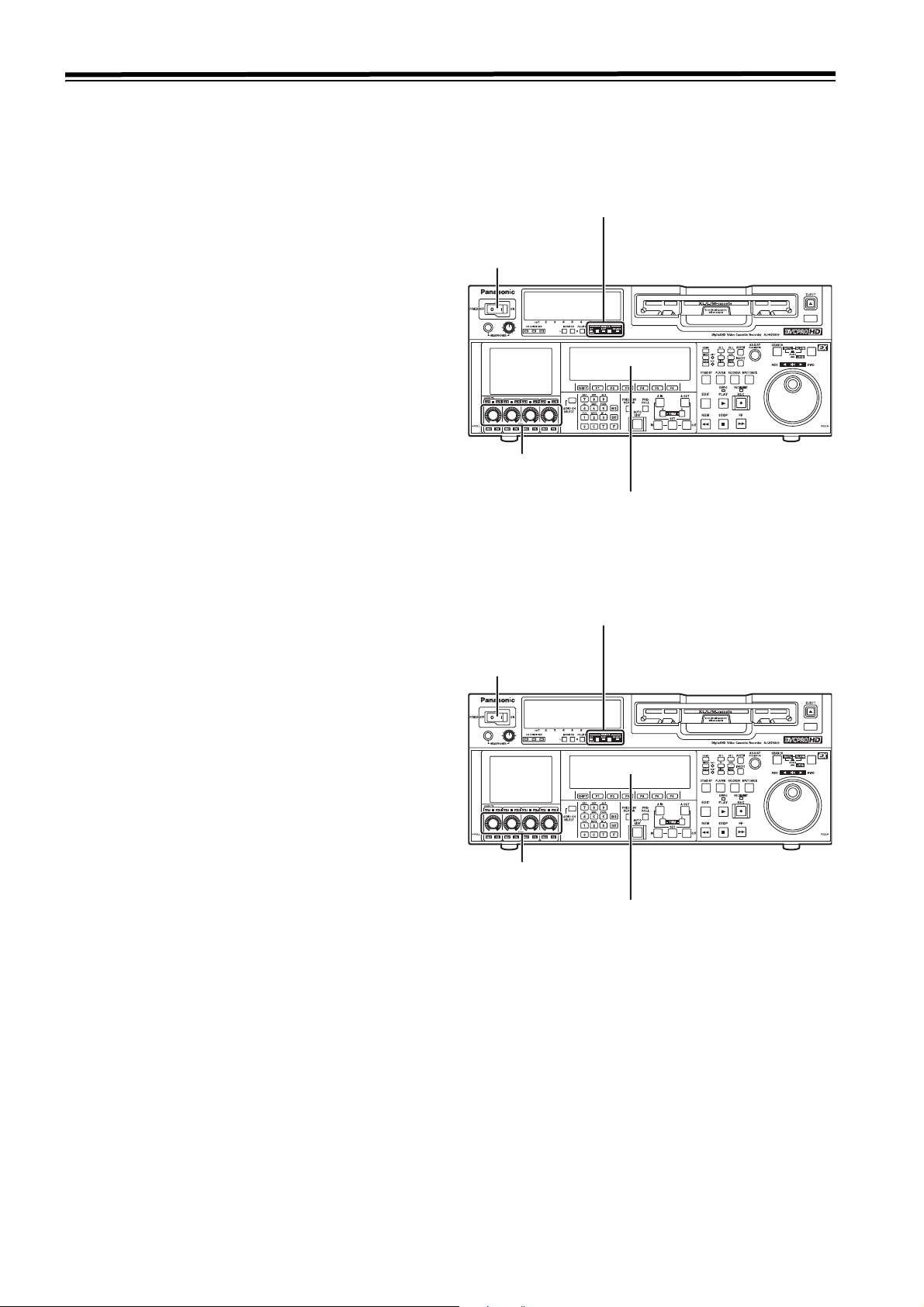
Automatic Editing (deck-to-deck)
A
“Editing” refers to the work involved in using pre-recorded
tapes to bring different contents together or delete
unnecessary parts and bring together only the necessary
parts.
The basic editing steps are as follows.
1 Using the REMOTE button, set the player to REMOTE
and the recorder to LOCAL (ensure that the REMOTE
LED is not lighted).
2 Select the editing mode (ASSEM or INSERT).
3 Register the edit points of the recorder and player.
4 Check and modify, if necessary, the edit points.
5 Preview the material before editing it.
6 Proceed with the editing (AUTO EDIT).
7 Review the edited results.
Switch settings and adjustments
When using this VTR as the recorder
Set the VTR to the LOCAL status
(which is indicated when the REMOTE
LED is OFF).
Set the POWER
switch to ON.
Adjust the recording
levels.
Switch the time counter display to TC
or CTL.
When using this VTR as the player
Press the 9P button for 2 or more
seconds to set the VTR to the REMOTE
status which is indicated when the
REMOTE LED is ON.
Set the POWER
switch to ON.
djust the playback
levels.
Switch the time counter display to TC
or CTL.
30
 Loading...