

Page 1
Operating Instructions
P
Memory Card Camera-Recorder
Model No. AG-UX90
Please read these instructions carefully before using this product, and save this manual for future
use.
PJ
F1016YA0
ENGLISH
DVQP1146ZA
Page 2

Information for Your Safety
WARNING:
To reduce the risk of fire, electric shock or product damage,
≥ Do not expose this unit to rain, moisture, dripping or splashing.
≥ Do not place objects filled with liquids, such as vases, on this unit.
≥ Use only the recommended accessories.
≥ Do not remove covers.
≥ Do not repair this unit by yourself. Refer servicing to qualified service personnel.
CAUTION!
To reduce the risk of fire, electric shock or product damage,
≥ Do not install or place this unit in a bookcase, built-in cabinet or in another confined space.
Ensure this unit is well ventilated.
≥
Do not obstruct this unit’s ventilation openings with newspapers, tablecloths, curtains, and similar items.
≥ Do not place sources of naked flames, such as lighted candles, on this unit.
(For the U.S.A. and Canada only)
AC adaptor
This AC adaptor operates on AC between 100 V and 240 V.
But
≥ In the U.S.A. and Canada, the AC adaptor must be connected to a 120 V AC power supply only.
≥ When connecting to an AC supply outside of the U.S.A. or Canada, use a plug adaptor to suit
the AC outlet configuration.
≥ When connecting to a supply of greater than AC 125 V, ensure the cord you use is suited to the
voltage of the AC supply and the rated current of the AC adaptor.
≥
Contact an electrical parts distributor for assistance in selecting a suitable AC plug adaptor or AC cord set.
The power plug is the disconnecting device. Install this unit so that the power plug can be
unplugged from the socket outlet immediately.
(Except for the U.S.A. and Canada)
The mains plug is the disconnecting device. Install this unit so that the mains plug can be
unplugged from the socket outlet immediately.
This unit is intended for use in moderate climates.
- 2 -
Page 3

IMPORTANT SAFETY
INSTRUCTIONS
Read these operating instructions carefully
before using the unit. Follow the safety
instructions on the unit and the applicable
safety instructions listed below. Keep these
operating instructions handy for future
reference.
1) Read these instructions.
2) Keep these instructions.
3) Heed all warnings.
4) Follow all instructions.
5) Do not use this apparatus near water.
6) Clean only with dry cloth.
7) Do not block any ventilation openings.
Install in accordance with the
manufacturer’s instructions.
8) Do not install near any heat sources such
as radiators, heat registers, stoves, or
other apparatus (including amplifiers) that
produce heat.
9) Do not defeat the safety purpose of the
polarized or grounding-type plug. A
polarized plug has two blades with one
wider than the other. A grounding-type plug
has two blades and a third grounding
prong. The wide blade or the third prong
are provided for your safety. If the provided
plug does not fit into your outlet, consult an
electrician for replacement of the obsolete
outlet.
10) Protect the power cord from being walked
on or pinched particularly at plugs,
convenience receptacles, and the point
where they exit from the apparatus.
11) Only use attachments/accessories
specified by the manufacturer.
12) Use only with the
cart, stand, tripod,
bracket, or table
specified by the
manufacturer, or sold
with the apparatus.
When a cart is used,
use caution when
moving the cart/apparatus combination to
avoid injury from tip-over.
13) Unplug this apparatus during lightning
storms or when unused for long periods of
time.
14) Refer all servicing to qualified service
personnel. Servicing is required when the
apparatus has been damaged in any way,
such as power-supply cord or plug is
damaged, liquid has been spilled or objects
have fallen into the apparatus, the
apparatus has been exposed to rain or
moisture, does not operate normally, or has
been dropped.
- 3 -
Page 4

FCC NOTICE (USA)
AG-UX90
Declaration of Conformity
Model Number: AG-UX90P, AG-UX90PJ
Trade Name: Panasonic
Responsible Party: Panasonic Corporation of North America
Support contact: 1-800-524-1448
This device complies with Part 15 of the FCC Rules.
Operation is subject to the following two conditions:
(1) This device may not cause harmful interference, and (2) this device must accept any
interference received, including interference that may cause undesired operation.
To assure continued compliance, follow the attached installation instructions and do not make
any unauthorized modifications.
CAUTION:
This equipment has been tested and found to comply with the limits for a Class B digital
device, pursuant to Part 15 of the FCC Rules. These limits are designed to provide reasonable
protection against harmful interference in a residential installation. This equipment generates,
uses and can radiate radio frequency energy and, if not installed and used in accordance with
the instructions, may cause harmful interference to radio communications. However, there is
no guarantee that interference will not occur in a particular installation. If this equipment does
cause harmful interference to radio or television reception, which can be determined by turning
the equipment off and on, the user is encouraged to try to correct the interference by one or
more of the following measures:
≥ Reorient or relocate the receiving antenna.
≥ Increase the separation between the equipment and receiver.
≥ Connect the equipment into an outlet on a circuit different from that to which the receiver is
connected.
≥ Consult the dealer or an experienced radio/TV technician for help.
The user may find the booklet “Something About Interference”
available from FCC local regional offices helpful.
FCC Warning:
To assure continued FCC emission limit compliance, follow the attached installation
instructions and the user must use only shielded interface cables with ferrite core when
connecting to host computer or peripheral devices. Also, any unauthorized changes or
modifications to this equipment could void the user’s authority to operate this device.
NOTIFICATION (Canada)
CAN ICES-3(B)/NMB-3(B)
Two Riverfront Plaza Newark NJ07102
indicates safety information.
THE FOLLOWING APPLIES ONLY IN THE U.S.A.
- 4 -
Page 5
∫ Concerning the battery
U.S.A./CANADA CONSUMERS: ATTENTION:
A lithium ion battery that is recyclable powers the product
you have purchased. Please call 1-800-8-BATTERY for
information on how to recycle this battery.
Battery pack (Lithium ion battery pack)
≥ Use the specified unit to recharge the battery pack.
≥ Do not use the battery pack with equipment other than the specified unit.
≥ Do not get dirt, sand, liquids, or other foreign matter on the terminals.
≥ Do not touch the plug terminals (i and j) with metal objects.
≥ Do not disassemble, remodel, heat or throw into fire.
If any electrolyte should come into contact with your hands or clothes, wash it off thoroughly with
water.
If any electrolyte should come into contact with your eyes, never rub the eyes. Rinse eyes
thoroughly with water, and then consult a doctor.
Warning
Risk of fire, explosion and burns. Do not disassemble, heat above 60 oC (140 oF) or incinerate.
CAUTION
≥ Danger of explosion if battery is incorrectly replaced. Replace only with the type
recommended by the manufacturer.
≥ When disposing of the batteries, please contact your local authorities or dealer and ask for the
correct method of disposal.
∫ Product identification marking
Product Location
Memory Card Camera-Recorder Bottom
Battery charger Bottom
AC adaptor Bottom
Conforms to UL STD 60065.
Certified to CAN/CSA STD C22.2 No.60065.
- 5 -
Page 6

∫ Cautions for use
About this unit
The unit and the SD card become warm
during use. This is not a malfunction.
Keep this unit as far away as possible from
electromagnetic equipment (such as
microwave ovens, TVs, video games etc.).
≥ If you use this unit on top of or near a TV, the
pictures and/or sound on this unit may be
disrupted by electromagnetic wave radiation.
≥ Do not use this unit near cell phones because
doing so may result in noise adversely
affecting the pictures and/or sound.
≥ Recorded data may be damaged, or pictures
may be distorted, by strong magnetic fields
created by speakers or large motors.
≥ Electromagnetic wave radiation generated by
microprocessors may adversely affect this
unit, disturbing the pictures and/or sound.
≥ If this unit is adversely affected by
electromagnetic equipment and stops
functioning properly, turn this unit off and
remove the battery or disconnect AC adaptor.
Then reinsert the battery or reconnect AC
adaptor and turn this unit on.
Do not use this unit near radio transmitters
or high-voltage lines.
≥ If you record near radio transmitters or
high-voltage lines, the recorded pictures and/
or sound may be adversely affected.
About connecting to a PC
≥ A USB 3.0 cable is not supplied with this unit.
Use a commercially-available doubleshielded USB 3.0 cable with a ferrite core.
If possible, we recommend using a cable with
a length of 1.5 m (4.9 feet) or less.
About using a headphone
≥
Excessive sound pressure from earphones
and headphones can cause hearing loss.
≥ Listening at full volume for long periods may
damage the user ’s ears.
Make sure to use the supplied cords and
cables. If you use optional accessories, use the
cords and the cables supplied with them.
Do not extend the cords and the cables.
Do not spray insecticides or volatile
chemicals onto the unit.
≥ If the unit is sprayed with such chemicals, its
body may be marred and the surface finish
may peel off.
≥ Do not leave rubber or plastic products in
contact with the unit for a long time.
When you use the unit in a sandy or dusty
place such as a beach, do not let sand or
fine dust get into the body and terminals of
the unit.
Also, keep the unit away from sea water.
≥ Sand or dust may damage the unit. (Care
should be taken when inserting and removing
a card.)
≥ If sea water splashes onto the unit, wipe off
the water with a well wrung cloth. Then wipe
the unit again with a dry cloth.
When carrying the unit, do not drop or bump
it.
≥ A strong impact can break the unit’s casing,
causing it to malfunction.
≥ When carrying this unit, please hold the
handle, hand strap or shoulder strap firmly
and treat it with care.
Cleaning
≥ Before cleaning, detach the battery or pull the
AC cable from the AC outlet, and then wipe
the unit with a soft, dry cloth.
≥ If the unit is very dirty, dip a cloth in water and
squeeze firmly, and then wipe the unit with
the damp cloth. Next, dry the unit with a dry
cloth.
≥ Use of benzine, paint thinner, alcohol, or
dishwashing liquid may alter the camera body
or peel the surface finish. Do not use these
solvents.
≥ When using a chemical dust cloth, follow the
instructions that came with the cloth.
When you are not going to use the unit for
an extended time
≥ When storing the unit, it is recommended that
you place a desiccant (silica gel) in with it.
Do not lift up this unit by the handle with the
tripod still attached
≥ When the tripod is attached, its weight will
also affect the unit’s handle, possibly causing
the handle to break and hurting the user.
- 6 -
Page 7

≥ To carry the unit while the tripod is attached,
take hold of the tripod.
Do not swing the unit around, shake it by, or
allow it hang from the handle
≥ Do not jar, swing, or shake the unit by its
handle. Any strong jolt to the handle may
damage the unit or result in personal injury.
Do not allow the cord to drag on the ground
or pull a connected cord along the passage
≥
The cord will be damaged, causing fire or
electrical shock, when the cord gets caught by
the feet, excite will also cause personal injury.
When this unit is turned on, do not use it in
direct contact with the skin for a long period
of time.
≥ When using this unit for a long period of time,
use a support such as a tripod. Low
temperature burns may result if any high
temperature part of this unit is in direct
contact with the skin for a long period of time.
About the battery
The battery used in this unit is a rechargeable
lithium-ion battery. It is susceptible to humidity
and temperature and the effect increases the
more the temperature rises or falls. In cold
areas, the full charge indication may not appear
or the low battery indication may appear about
5 minutes after starting use. At high
temperatures, the protection function may be
triggered, making it impossible to use the unit.
Be sure to detach the battery after use.
≥ If the battery is left attached, a minute amount
of current continues to flow even if the unit is
off. Keeping the unit in this state may result in
over discharge of the battery. This may result
in you not being able to use the battery even
after it is charged.
≥ The battery should be stored in the vinyl bag
so metal does not come into contact with the
terminals.
≥ The battery should be stored in a cool place
free from humidity, with as constant
temperature as possible. (Recommended
temperature: 15 oC to 25 oC (59 oF to 77 oF),
Recommended humidity: 40%RH to 60%RH)
≥
Extremely high temperatures or low
temperatures will shorten the life of the battery.
≥ If the battery is kept in high-temperature,
high-humidity, or oily-smoky places, the
terminals may rust and cause malfunctions.
≥ To store the battery for a long period of time,
we recommend you charge it once every year
and store it again after you have completely
used up the charged capacity.
≥ Dust and other matter attached to the battery
terminals should be removed.
Prepare spare batteries when going out for
recording.
≥ Prepare batteries enough to last for 3 to 4
times the period you are planning to record
for. Cold places such as a ski resort can
shorten recording time.
If you drop the battery accidentally, check to
see if the terminals are damaged.
≥ When this unit or battery charger is attached
with the terminal part in a deformed state, this
unit or battery charger may be damaged.
Do not throw old battery into fire.
≥ Heating a battery or throwing it into a fire may
result in an explosion.
If the operating time is very short even after
the battery has been recharged, the battery
has worn out. Please purchase a new
battery.
About the AC adaptor/battery
charger
≥ If the temperature of the battery is extremely
high or extremely low, charging may take time
or the battery may not be charged.
≥ If the CHARGE indicators keeps flashing in
orange, make sure that the terminals of the
battery or the battery charger are not
exposed to dirt, foreign objects or dust, then
reconnect them properly.
Disconnect the AC cable from the AC outlet
when you remove dirt, foreign objects or dust
on the terminals of the battery or the battery
charger.
≥ If the battery’s temperature is excessively
high or excessively low, the CHARGE
indicators will blink orange. Charging will start
automatically when the battery reaches an
acceptable temperature for charging.
- 7 -
Page 8

≥ If the CHARGE indicators blinks orange when
the battery’s temperature is normal, the
battery or the battery charger may be
malfunctioning. In such cases, contact your
dealer.
≥ If you use the AC adaptor or battery charger
near a radio, radio reception may be
disturbed. Keep the AC adaptor or battery
charger 1 m (3.3 feet) or more away from the
radio.
≥ When using the AC adaptor or battery
charger, it may generate whirring sounds.
However, this is normal.
≥ After use, be sure to disconnect the AC cable
from the AC outlet. (If you leave this unit
connected, the AC adaptor will consume
approximately 0.1 W.)
≥ Always keep the electrodes of the AC
adaptor, battery charger and battery clean.
≥ Install the device near an AC outlet so that
the power disconnection device (AC
mains plug) can be accessed easily by
hand.
About the SD card
When disposing of or giving away the SD
card, note that:
≥ Formatting and deletion of this unit or
computer only changes the file management
information and does not completely delete
the data in the SD card.
≥ It is recommended that the main SD card is
either physically destroyed or the SD card is
physically formatted using this unit when
disposing of or giving away the SD card.
≥ To physically format, connect this unit to the
AC adaptor, select [OTHER FUNCTION] #
[FORMAT MEDIA] # [SD CARD 1] or [SD
CARD 2] from the menu, and touch [YES].
Press and hold recording start/stop button in
the following screen for three seconds.
Screen to delete the SD card data is
displayed, so select [YES] and follow the
instruction on the screen.
≥ The customer is responsible for the
management of the data in the SD card.
LCD monitor/viewfinder
≥ When the LCD screen is dirty or
condensation has occurred, please wipe it
using a soft cloth such as a lens cloth.
≥ Do not touch the LCD monitor with your finger
nails, or rub or press with strong force.
≥ It may become hard to see or hard to
recognize the touch when the LCD protection
sheet is affixed.
≥ When the unit has become very cold, for
example due to storage in a cold area, its
LCD monitor will be slightly darker than usual
immediately after the unit is turned on. The
normal brightness will be restored when the
unit’s internal temperature rises.
Extremely high precision technology is
employed to produce the LCD Monitor
screen. The result is more than 99.99%
effective dots with a mere 0.01% of the dots
inactive or always lit. However, this is not a
malfunction and does not affect the recorded
picture.
Extremely high precision technology is
employed to produce the viewfinder screen.
The result is more than 99.99% effective
dots with a mere 0.01% of the dots inactive
or always lit. However, this is not a
malfunction and does not affect the recorded
picture.
About personal information
When this unit is connected to iPad, the SSID,
Password, and other personal information will
be included in this unit.
Setting a [NETWORK SETUP PASSWORD] is
recommended to protect personal information.
(l 179)
Disclaimer
≥ Information including personal information
may be altered or vanish due to erroneous
operation, effect of static electricity, accident,
malfunction, repair, or other handlings.
Please note in advance that Panasonic is not
liable in any way for any direct or indirect
- 8 -
Page 9

damage from the alteration or vanishing of
information or personal information.
When requesting a repair, transferring to
another party, or disposing.
≥
After making a copy of personal information,
always delete information such as personal
information and wireless LAN connection
settings that you have saved within this unit with
[NETWORK INITIAL SETTING]/[INITIAL SET].
(l
177, 178
≥ Remove the Memory Card from this unit
when requesting a repair.
≥ Settings may return to factory default when
this unit is repaired.
≥ Please contact the dealer where you
purchased this unit or Panasonic if above
operations are not possible due to
malfunction.
When transferring to another party, or
disposing of the Memory Card, please refer
to “When disposing of or giving away the
SD card, note that:”. (l 8)
)
∫ About the recording method
for recording motion pictures
This unit can record motion pictures using three
different recording methods, including MOV,
MP4 and AVCHD
* AVCHD Progressive (1080/60p) supported.
MOV and MP4:
These recording methods are suitable for
editing images. Audio is recorded in linear
PCM.
≥ Those methods are not compatible with
motion pictures recorded in AVCHD format.
≥ Those methods can record motion pictures in
formats that support 4K. 4K motion pictures
offer a resolution four times higher than that
of full high-definition motion pictures.
AVCHD:
This recording method is suitable for playback
on a high-definition compatible external monitor.
Audio is recorded in Dolby
*
. (l 43, 148)
®
Digital.
∫ Indemnity about recorded
content
Panasonic does not accept any responsibility for
damages directly or indirectly due to any type of
problems that result in loss of recording or edited
content, and does not guarantee any content if
recording or editing does not work properly.
Likewise, the above also applies in a case where
any type of repair is made to the unit.
∫ About Condensation
(When the lens, the viewfinder
or LCD Monitor is fogged up)
Condensation occurs when there is a change in
temperature or humidity, such as when the unit
is taken from outside or a cold room to a warm
room. Please be careful, as it may cause the
lens, the viewfinder or LCD monitor to become
soiled, moldy, or damaged.
When taking the unit to a place which has a
different temperature, if the unit is accustomed
to the room temperature of the destination for
about one hour, condensation can be
prevented. (When the difference in temperature
is severe, place the unit in a plastic bag or the
like, remove air from the bag, and seal the bag.)
When condensation has occurred, remove the
battery and/or the AC adapter and leave the
unit like that for about one hour. When the unit
becomes accustomed to the surrounding
temperature, fogginess will disappear naturally.
∫ About security
Be careful about the possibility of theft or loss of
the unit, and be careful not to leave the unit
unattended. Please note that Panasonic does
not accept any responsibility for the
compromise, manipulation, and loss of
information caused by these events.
∫ Caution regarding laser beams
The lens may suffer damage if struck by a laser
beam. Make sure that laser beams do not strike
the lens when shooting in an environment
where laser devices are used.
∫ Cards that you can use with
this unit
SDHC Memory Card and SDXC Memory Card
≥ 4 GB or more Memory Cards that do not have
the SDHC logo or 48 GB or more Memory
Cards that do not have the SDXC logo are
not based on SD Memory Card
Specifications.
≥ Refer to page 30 for more details on SD
cards.
- 9 -
Page 10

∫ For the purposes of these
operating instructions
≥ The battery pack is referred to as the
“Battery”.
≥ SDHC Memory Card and SDXC Memory
Card are referred to as the “SD card”.
≥ Function that can be used for Recording
Mode:
Function that can be used for Playback
Mode:
≥ Scene(s) recorded with [REC MODE] set to
[MOV] or [MP4]: "MOV/MP4 scene(s)".
≥ Scene(s) recorded with [REC MODE] set to
[AVCHD]: "AVCHD scene(s)".
≥ Pages for reference are indicated by an
arrow, for example: l 00
≥ These operating instructions are designed for
use with models AG-UX90P/PJ. Such as
screen illustrations are as an example AGUX90PJ.
- 10 -
Page 11

Contents
Information for Your Safety ......................... 2
Accessories ................................................. 13
Optional accessories .................................. 14
Preparation
What you can do with this unit ..................15
Recording to the SD card ....................... 15
Linking to external devices ..................... 15
Remote operations with an iPad............. 16
Names and Functions of
Main Parts .................................................... 17
Power supply ............................................... 24
Charging the battery ............................... 24
Inserting/removing the battery ................ 26
Charging and recording time .................. 27
Connecting to the AC outlet.................... 29
Preparation of SD cards ............................. 30
Cards that you can use
with this unit ............................................ 30
Inserting/removing an SD card ............... 31
Turning the unit on/off ................................ 32
Selecting a mode ........................................ 32
Using the LCD monitor/Viewfinder ............ 33
Switching between the LCD monitor
and viewfinder displays .......................... 33
Using the LCD monitor ........................... 34
How to use the touch screen .................. 35
LCD monitor adjustment......................... 36
Viewfinder adjustment ............................ 37
Recording yourself.................................. 38
Setting date and time .................................. 39
Using the menu screen .............................. 41
Recording
Before recording ......................................... 42
Selecting a media to record ....................... 42
Formatting media.................................... 43
Recording motion picture .......................... 43
Switching between Auto and
Manual Mode ............................................... 45
Adjusting the Picture Quality ..................... 47
Using the zoom ........................................... 49
Image Stabilizer Function .......................... 51
Focus ........................................................... 53
One Push AF .......................................... 56
Push AF .................................................. 57
Focus Assist ........................................... 57
White Balance ............................................. 61
Iris/Gain adjustment ................................... 65
Iris adjustment ........................................ 65
Gain adjustment ......................................67
Manual shutter speed .................................70
Audio Input ..................................................72
Switching Audio Input .............................72
Adjusting the audio input level ................74
Counter display ........................................... 76
Setting the Time Code ............................76
Setting the User Information ...................78
Setting the Recording Counter................ 79
USER button ................................................ 80
Setting the USER button.........................80
Using the USER button ...........................81
Functions of the USER button ................82
Useful functions .......................................... 99
Color Bar Screen ....................................99
ND filter ................................................. 100
Switching the screen indications/
mode information display ......................100
Using Operation Icons ..............................101
Using of jog dial ........................................102
Playback
Motion picture/
Still picture playback ................................105
Motion picture playback using
operation icon .......................................109
Useful functions ........................................ 110
Creating still picture from
motion picture .......................................110
Repeat Playback ...................................111
Resuming the previous playback .......... 111
Playing back scenes or
still pictures by date ..............................112
Editing
Deleting scenes/still pictures ...................113
Protecting scenes/still pictures..............114
Copying between SD cards ...................... 115
- 11 -
Page 12

Linking to external devices
Others
Connecting Headphones, a Remote
Control or an External Monitor ................ 117
Headphones ......................................... 117
Remote control ..................................... 117
External monitor ................................... 118
Setting the external output
resolution .............................................. 120
Connecting to a PC
(File transfer/nonlinear editing) ...............122
Operating environment
(mass storage)...................................... 122
Connecting to a PC .............................. 123
About the PC display ............................ 124
Copying/playing back with an external
media device ............................................. 126
Preparing for copying/playing back
Copy once ............................................ 128
Copy selected files ............................... 129
Playing back the External Media .......... 130
Using an iPad as a Remote Control
(AG ROP application) ............................... 131
Before connection................................. 132
Connecting this unit and an iPad.......... 135
Operations during AG ROP
application connection .......................... 139
.......... 126
Menu
Using the Menu ......................................... 140
Scene file .............................................. 140
System mode........................................ 148
User switch ........................................... 152
Switch setting ....................................... 153
Auto switch setting................................ 160
Recording Setup ................................... 162
Audio Setup .......................................... 166
Output Setup ........................................ 168
Display setting ...................................... 170
Other Functions .................................... 175
Network Setup ...................................... 178
Maintenance ......................................... 179
Video Setup .......................................... 180
Picture Setup ........................................ 181
Copy ..................................................... 181
Troubleshooting ........................................ 193
About recovery ......................................197
Updating the firmware incorporated
into the unit ................................................197
About copyright ........................................198
Recording functions that cannot be
used simultaneously .................................200
Recording modes/approximate
recordable time ......................................... 201
Approximate number of
recordable pictures ...................................202
Specification .............................................. 203
Display
Indications ................................................. 182
Messages ................................................... 185
Warning Indications .................................. 190
- 12 -
Page 13
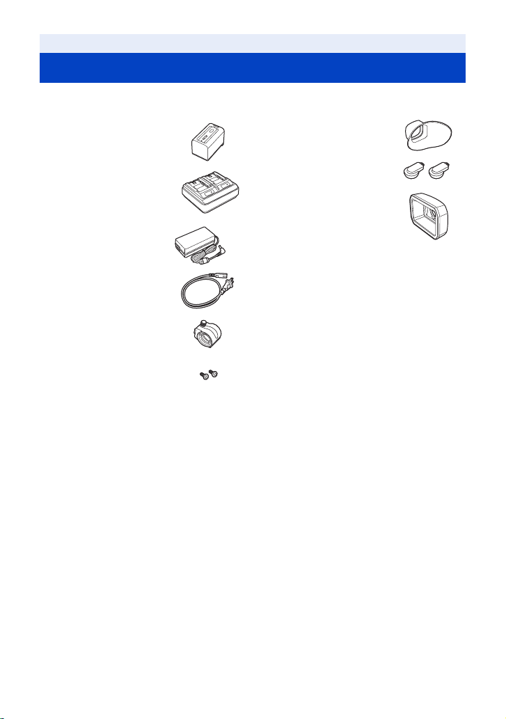
Accessories
Check the accessories before using this unit.
Keep the accessories out of reach of children to prevent swallowing.
Battery pack*
Battery charger
AC adaptor
AC cable
Microphone holder (l 23)
Microphone holder
mounting screws (l 23)
12 mm length (0.47 q )
(2 screws)
1
Eye cup (l 22)
INPUT terminal cap
*2
(2 caps)
Lens hood
*1 The part number of the battery pack is AG-
*2 The INPUT terminal caps are supplied with
*3 The lens hood is attached to this unit at the
*3
VBR59. Before purchasing an extra battery
pack, check the optional accessories
section. To purchase extra accessories,
contact your dealer.
the microphone holder.
time of purchase.
- 13 -
Page 14

Optional accessories
Some optional accessories may not be available in some countries.
Product numbers correct as of September 2016. These may be subject to change.
Unidirectional microphone (AG-MC200G)
Battery pack (VW-VBD58/AG-VBR59/AG-VBR89/AG-VBR118)
Battery charger (AG-B23/AG-BRD50)
LED video light (VW-LED1)
- 14 -
Page 15
Preparation
What you can do with this unit
Recording to the SD card
It is possible to record motion pictures and still pictures to the SD card using a variety of recording
functions.
≥ This unit supports relay/simultaneous recording using double card slots.
Linking to external devices
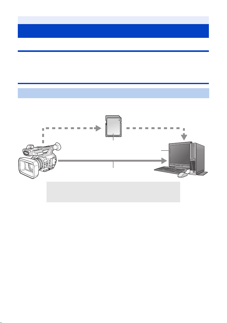
USB Device Mode
Transfer data (files) to perform nonlinear editing on another device (PC, etc.).
≥ This unit supports USB 3.0.
A SD card*
B USB 3.0 (Device mode)*
C PC
*1 SD cards are optional and not supplied with this unit.
*2 A USB 3.0 cable is not supplied with this unit. Use a commercially-available double-shielded
USB 3.0 cable with a ferrite core.
If possible, we recommend using a cable with a length of 1.5 m (4.9 feet) or less.
1
2
- 15 -
Page 16
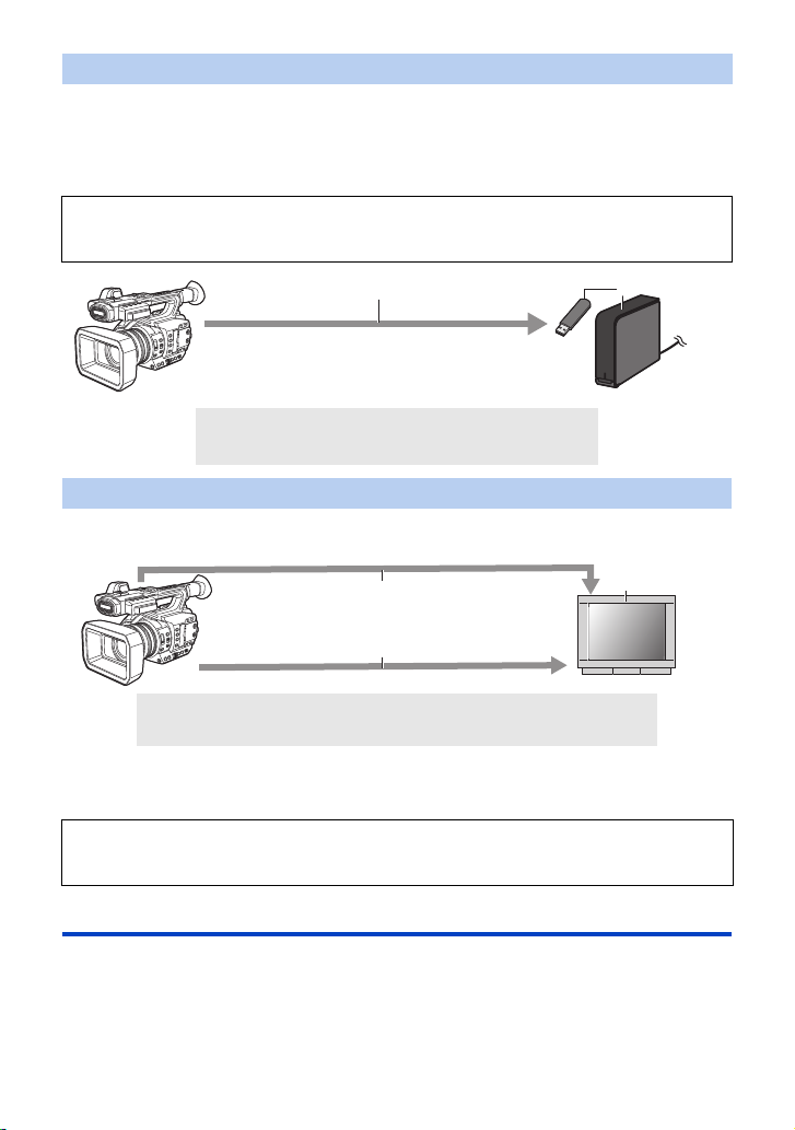
USB Host Mode
If you connect an external media device, such as USB HDD or USB flash memory (commerciallyavailable) to this unit, you can copy motion pictures and still pictures recorded on this unit to the
external media device.
It can also play back the scenes and still pictures copied to the external media device.
≥ This unit supports USB 3.0.
Refer to the following support site for information about an external media device.
http://pro-av.panasonic.net/
(This Site is English only)
A USB 3.0 (Host mode)
B External media device (commercially-available)
Connecting to an external monitor
Connect an external monitor to output images.
A AV c a ble *
B HDMI cable*
*1 Use a commercially-available AV cable.
*2 Use a commercially-available High Speed HDMI cable.
If possible, we recommend using a cable with a length of 3 m (9.84 feet) or less.
When connecting with an HDMI cable using an HDMI-to-DVI converter, etc., be sure to
connect the HDMI cable to the connector of this unit last.
Connecting the HDMI cable to the connector of this unit first may result in malfunction.
1
2
C External monitor
Remote operations with an iPad
Attaching a wireless module that support this unit (l 132) to the USB HOST terminal of this unit
allows you to connect to a wireless LAN network. You can perform the following operations by
connecting this unit and an iPad on which the AG ROP application is installed:
≥ Checking the camera status
≥ Checking the thumbnail images of recorded scenes
≥ Controlling the camera remotely (recording control and Time Code/User Information operations)
- 16 -
Page 17
Preparation
Names and Functions of Main Parts
4
5
6
1
2
3
13
15
16
14
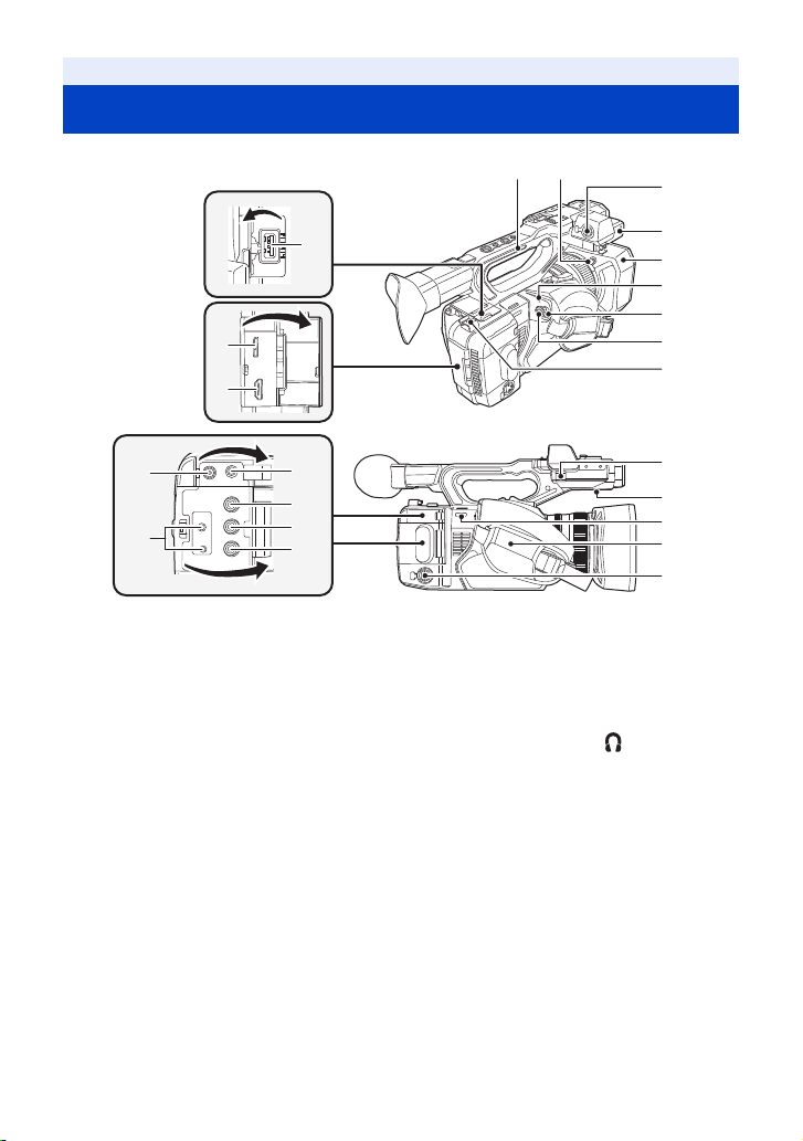
1 USB HOST terminal (l 126, 131)
2 USB DEVICE terminal (l 123)
3 HDMI OUT connector [HDMI] (l 11 8)
4 Handle
5 Lens hood release button (l 21)
6 Audio input terminal 1 (XLR 3 pin)
[AUDIO INPUT1] (l 23, 72)
7 Microphone holder attachment part
(l 23)
8 Lens hood (l 21)
9 Status indicator (l 32)
10 Power switch (l 32)
11 Recording start/stop button (l 43)
12 Cable holder
≥ Secures an HDMI cable.
13 DC input terminal [DC IN] (l 29)
≥ Do not use any other AC adaptors except the
supplied one.
17
18
7
8
9
10
11
12
19
20
21
22
23
14 Camera remote terminal [CAM
REMOTE] (l 11 7)
≥ FOCUS IRIS terminal (3.5 mm (0.14 q)
diameter mini jack)
≥ ZOOM S/S terminal (2.5 mm (0.1 q) diameter
super mini jack)
15 Headphone terminal [ ] (l 104, 117 )
16 VIDEO OUT terminal (l 11 8)
17 AUDIO OUT CH1 terminal (l 118)
18 AUDIO
19 Microphone cable clamper (l 23)
20 Speaker
21 Shoulder strap fixture
22 Hand strap (l 22)
23 Audio input terminal 2 (XLR 3 pin)
OUT CH2 terminal (l 118)
[AUDIO INPUT2] (l 23, 72)
- 17 -
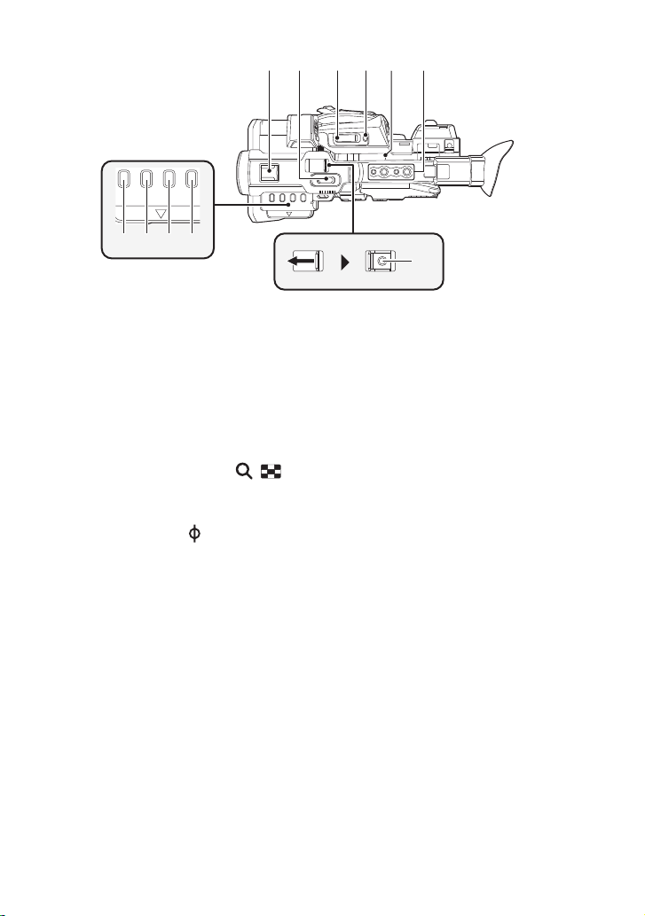
Page 18
29
30
26
27
28
31
32
33
34
35 3736
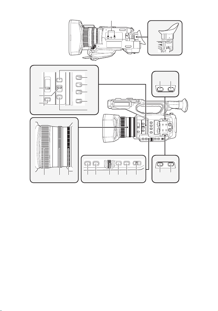
24 Tripod receptacle
≥ There are tripod mounting holes that are
compatible with 1/4-20UNC and 3/8-16UNC
screws. Use the size that matches the
diameter of the tripod’s fixing screw.
≥ Attaching a tripod with a screw length of
5.5 mm (0.22 q) or more may damage the
unit.
25 Eyepiece corrector lever (l 37)
26 ND filter switch [ND FILTER] (l 100)
27 Focus auto/Manual/¶ switch
[FOCUS A/M/¶] (l 53)
28 Iris button [IRIS] (l 65)
29 FOCUS ASSIST button (l 57)
30 User 1 button [USER1] (l 81)
31 User 2 button [USER2] (l 81)
32 User 3 button [USER3] (l 81)
33 Display/Mode check button [DISP/
MODE CHK] (l 81, 100)
24
4140 42 43 44 45
34 PUSH AUTO button (l 53)
35 Focus ring (l 53)
36 Zoom ring (l 49)
37 Iris ring (l 65)
38 User 6 button [O.I.S.] (l 51, 81)
39 User 7 button [LCD/EVF] (l 33, 80)
40 Gain button [GAIN] (l 67)
41 Wh
ite Balance button [WHITE BAL]
(l 61)
42 Jog dial [SEL/PUSH SET] (l 61, 67, 70,
102, 107)
43 Menu button [MENU] (l 41)
44 Shutter speed button [SHUTTER] (l 70)
45 Auto/Manual switch [AUTO/MANU]
(l 45)
46 User 4 button [USER4] (l 81)
47 User 5 button [ZEBRA] (l 81, 95)
- 18 -
25
38 39
47
46
Page 19
555453
48
57
56
59 60 626158
5049
5251
63
65
64
68
67
69
70
66
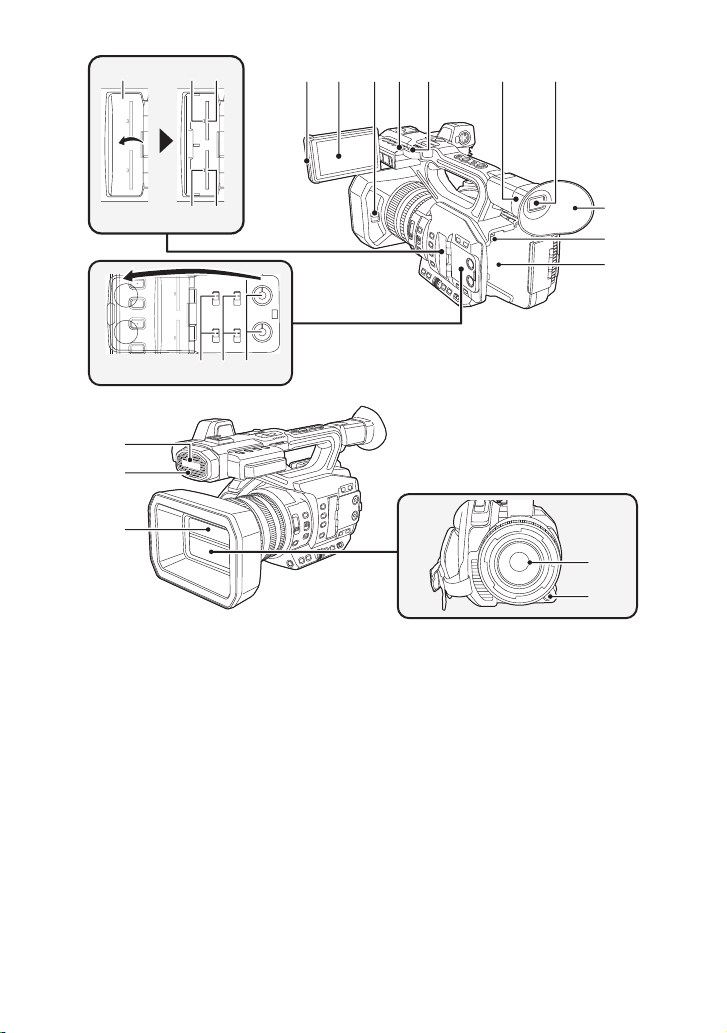
48 SD Card slot cover (l 31)
49 Access lamp (card 1) (l 31)
50 Card slot 1 (l 31)
51 Access lamp (card 2) (l 31)
52 Card slot 2 (l 31)
53 INPUT1 / INPUT2 switches (l 72)
54 CH1 SELECT/CH2 SELECT switches
55 AUDIO LEVEL CH1/AUDIO LEVEL CH2
56 LCD monitor extract part (l 34)
57 LCD monitor (Touch screen) (l 35)
58 Lens cover open/close lever (l 21)
59 Recording lamp (Rear) (l 175)
60 Shoulder strap fixture
(l 72)
knobs (l 74)
61 Eye cup mount (l 22)
62 Viewfinder (l 37)
63 Eye cup (l 22)
64 Battery release button [PUSH] (l 26)
65 Battery holder (l 26)
66 Built-in microphone
67 Recording lamp (Front) (l 175)
68 Lens cover (l 21)
69 L
ens (LEICA DICOMAR)
70 User 9 button [AWB] (l 61
- 19 -
, 81)
Page 20
71 72 73 74 75 76
77 78 79 80
71 Accessory shoe
72 Sub zoom lever (l 49, 159)
≥ This lever functions in the same manner as
the zoom lever.
≥ The zoom speed is controlled with this lever
in a way different from the way it is controlled
with the zoom lever. (l 50)
73 Zoom lever [T/W] (In Recording Mode)
(l 49)
Volume lever [rVOLs](l 107)/
Thumbnail display switch [ / ]
(l 106)
(In Playback Mode)
74 User 8 button [REC CHECK] (l 81, 86)
75 Focal plane index [ ]
≥ Indicates the focal plane of the MOS sensor.
76 Handle mounting hole
(Size of the mounting hole)
j 1/4-20UNCk2
j 3/8-16UNCk2
77 Thumbnail button [THUMBNAIL] (l 32)
78 Counter button [COUNTER] (l 76)
79 Counter reset [RESET] (l 78)
80 Color Bar Screen button [BARS] (l 99)
81 Sub recording start/stop button (l 158)
≥ This button functions in the same manner as
the recording start/stop button.
81
- 20 -
Page 21
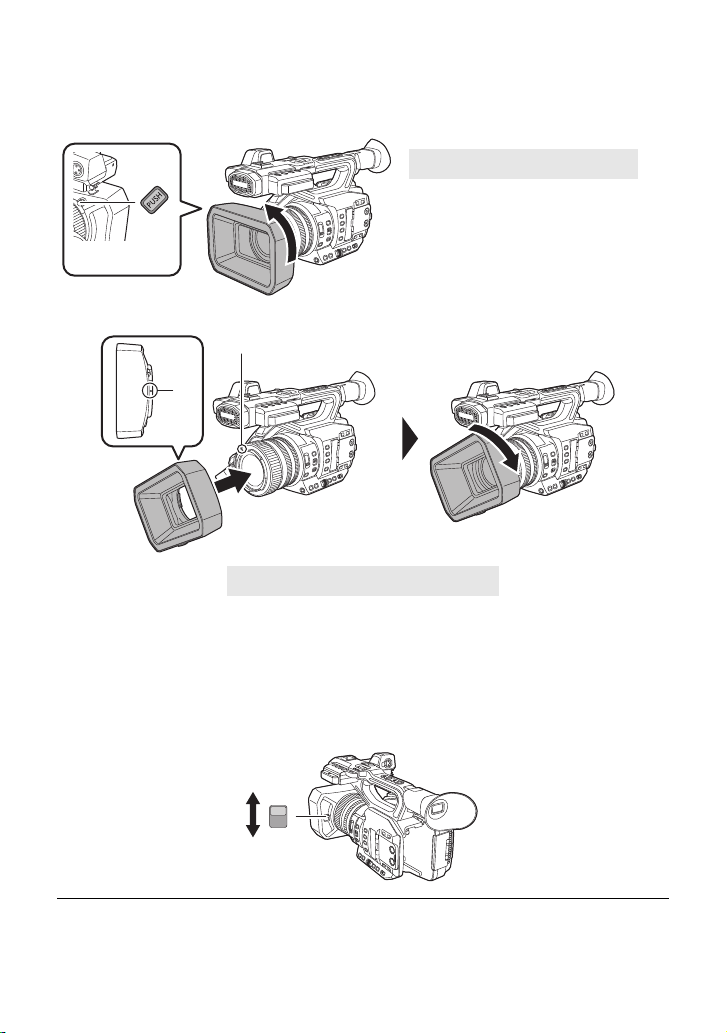
∫ Attaching/detaching the lens hood
(How to detach the lens hood)
While pressing and holding the lens hood release button, rotate the lens hood in
the direction of the arrow to detach it.
A Lens hood release button
(How to attach the lens hood)
B Mounting mark
1 Fit the lens hood into this unit.
≥ Align the mounting mark on the lens hood with the mounting mark on this unit.
2 Rotate the lens hood in the direction of the arrow.
≥ Rotate until it clicks into place.
Opening/closing the lens cover
You can open/close the lens cover by sliding the lens cover open/close lever.
≥ When this unit is not in use, close the lens cover to protect the lens.
OPEN
CLOSE
≥ Do not press the lens cover hard. This may damage the lens or the lens cover.
≥ Depending on the various filters or the MC protector attached to the front side of this unit's lens,
you may not be able to open/close the lens cover or attach the lens hood.
- 21 -
Page 22
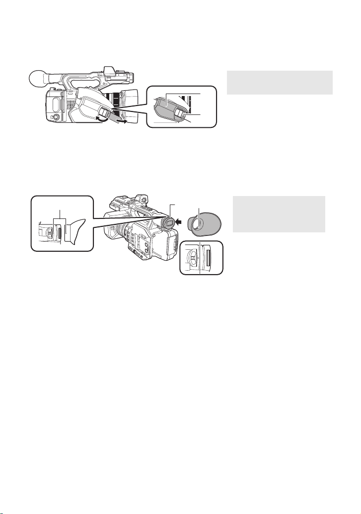
∫ Adjust the length of the hand strap so that it fits your hand.
Adjust the hand strap according to the size of your hand.
≥ If you find it difficult to fasten the buckle B, move the pad A forward, and fasten the buckle B
again.
1 Open the buckle.
2 Pull the end of the belt.
∫ Attaching the eye cup
1 Align the mounting mark on the eye cup mount with the corresponding mark on
the eyecup.
2 Attach the eye cup so that the notch on the eye cup mount is aligned with the
protrusion inside the eye cup.
A Mounting marks
B Notch
C Protrusion
≥ Push the eye cup in until it reaches the mounting mark. (D)
- 22 -
Page 23
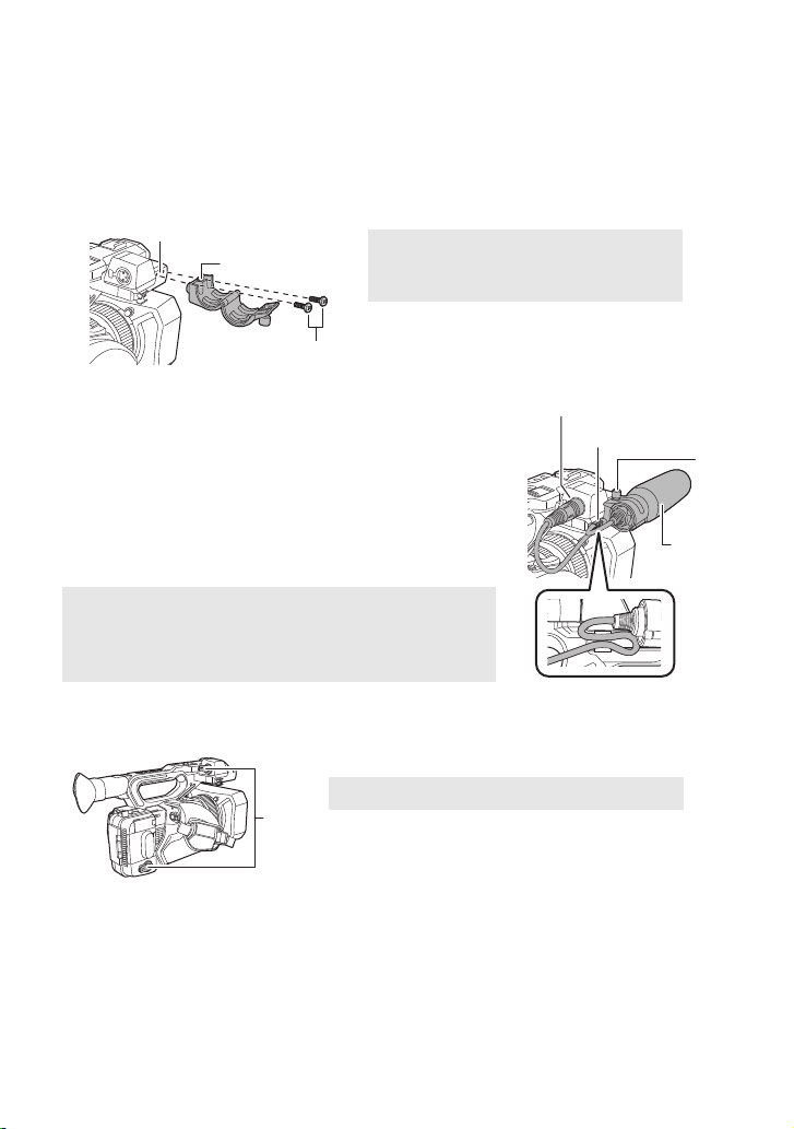
∫ Attaching the front microphone
≥ The microphone holder is set up so that a 21 mm (0.83 q) external microphone (AG-MC200G:
optional) can be attached. Check in advance whether the microphone you wish to use can be
attached.
1 Attach the microphone holder to the microphone holder attachment part.
≥ Attach by using a commercially available screw driver.
≥ When attaching the microphone holder, be sure to tighten the screws firmly even though you
might hear a squeaking sound.
2 Attach an external microphone (optional) to the
microphone holder, and tighten the microphone
holder screw.
3 Connect the external microphone to the AUDIO
INPUT1 terminal (XLR 3 pin).
≥ When wiring the microphone cable, use the cable clamper of
this unit.
≥ Keep the microphone holder screw and INPUT terminal cap
out of reach of children to prevent swallowing.
D AUDIO INPUT1 terminal (XLR 3 pin)
E Microphone cable clamper
F Microphone holder screw
G External microphone (optional)
A Microphone holder attachment part
B Microphone holder
C Microphone holder mounting screws
∫ Attaching the INPUT terminal cap
Attach the INPUT terminal cap while the AUDIO INPUT1, 2 terminals (XLR 3 pin) are not used.
A INPUT terminal cap
- 23 -
Page 24
Preparation
Power supply
∫ About batteries that you can use with this unit (as of September
2016)
The battery that can be used with this unit is VW-VBD58/AG-VBR59/AG-VBR89/AG-VBR118.
≥ The AG-VBR59/AG-VBR89/AG-VBR118 supports quick charging.
It has been found that counterfeit battery packs which look very similar to the genuine
product are made available to purchase in some markets. Some of these battery packs
are not adequately protected with internal protection to meet the requirements of
appropriate safety standards. There is a possibility that these battery packs may lead to
fire or explosion. Please be advised that we are not liable for any accident or failure
occurring as a result of use of a counterfeit battery pack. To ensure that safe products are
used we would recommend that a genuine Panasonic battery pack is used.
Charging the battery
When this unit is purchased, the battery is not charged. Charge the battery fully before
using this unit for the first time.
Important:
≥ Do not use the AC cable with any other equipment as it is designed only for this unit. Also,
do not use the AC cable from other equipment with this unit.
≥ It is recommended to charge the battery in a temperature between 10 oC and 30 oC (50 oF
and 86 oF). (The battery temperature should also be the same.)
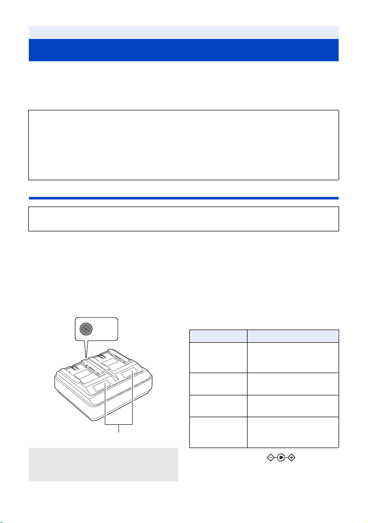
∫ About the Battery Charger
This unit can charge two battery packs simultaneously and supports quickcharging batteries.
CHARGE indicators [CHARGE 1/CHARGE 2]
A DC IN 12 V connector
B CHARGE indicators
[CHARGE 1/CHARGE 2
]
Indicate the charge status as follows.
Indicator Charge status
Lit green
Lit orange
Blinking orange
Off
DC IN 12 V connector [ ]
Connects to the DC plug of the AC adaptor.
Quick charging is in
progress. (Battery
charging time: l 27)
Normal charging is in
progress.
Charging has stopped due
to an error. (l 7)
Charging is complete, or a
battery pack is not
inserted.
- 24 -
Page 25
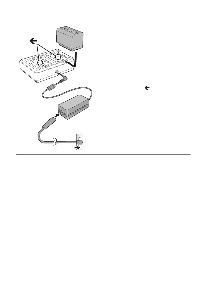
∫ Charging the battery
1 Connect the DC plug of the AC
adaptor to the DC IN 12 V
connector of battery charger.
2 Connect the AC mains lead to the
AC adaptor.
≥ Perform step 2 first, and then step 3. Insert
the AC mains lead all the way in until it stops.
3 Insert the battery into the battery
charger.
≥ Slide the battery horizontally into the battery
charger along the “ ” mark.
≥ The corresponding CHARGE indicator lights
and charging starts.
≥ The CHARGE indicator turns off when
charging is complete. Slide the battery to
remove it.
≥ We recommend using Panasonic batteries (l 27).
≥ If you use other batteries, we cannot guarantee the quality of this product.
≥ Do not heat or expose to flame.
≥ Do not leave the battery(ies) in a car exposed to direct sunlight for a long period of time with
doors and windows closed.
≥ After the battery is inserted, it may take some time for it to be detected and the CHARGE indicator
to light. If the CHARGE indicator does not light after 10 seconds, insert the battery again.
≥ If two batteries that support quick charging are inserted, priority will be given to the battery
inserted in the CHARGE 1 slot, and the battery inserted in the CHARGE 2 slot will be charged in
normal-charge mode. When charging on the CHARGE 1 slot progresses to a certain point,
charging on the CHARGE 2 slot will automatically switch to quick-charge mode.
In addition, the charge indicator (LED lamps) on the battery inserted in the CHARGE 2 slot may
turn off depending on the charge status of the battery.
≥ The battery charger determines the state of the battery first to perform optimal charging. It will, as
a result, take about 20 seconds for charging to start after the CHARGE indicator on the battery
charger lights. When charging starts, the charge indicator (LED lamps) on a battery that supports
quick charging will flash. If you remove and reinsert a battery or swap batteries while charging is
in progress on both the CHARGE 1 and CHARGE 2 slots, charging for both batteries will stop
temporarily, and the battery charger will determine the state of the batteries again before
restarting. Therefore, it will take about 20 seconds to restart charging.
≥ Insert the battery that you want charged first in the CHARGE 1 slot.
- 25 -
Page 26
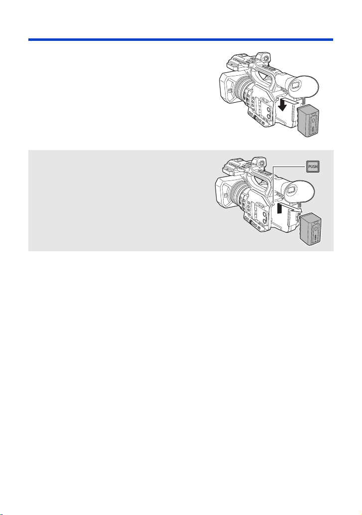
Inserting/removing the battery
Install the battery by inserting it in the
direction shown in the figure.
≥ Insert the battery until it clicks and locks.
Removing the battery
Make sure that the power switch is set to OFF and the
status indicator is turned off, and then remove by
holding onto it taking care not to drop. (l 32)
While pressing the battery release button, remove
the battery.
- 26 -
Page 27

Charging and recording time
Charging/Recording time
Battery model number
Supplied battery/
AG-VBR59 (optional)
AG-VBR89 (optional) 7.28 V/8850 mAh 4 h 10 h 10 min
AG-VBR118 (optional) 7.28 V/11800 mAh 4 h 40 min 13 h 25 min
VW-VBD58 (optional) 7.2 V/5800 mAh 5 h 20 min 6 h 50 min
≥ The above charging times apply when the supplied battery charger is used.
≥ The times given apply when the ambient operating temperature is 25 oC (77 oF) and the relative
operating humidity is 60%. Charging time may be longer at other temperatures and humidity
levels.
≥ The continuous recordable time given applies under the conditions below. The time becomes
shorter under other conditions.
j The LCD monitor is open
j A cable is not inserted to the external output terminal
≥ “h” is an abbreviation for hour, “min” for minute and “s” for second.
≥ These times are approximations.
≥ The indicated charging time is for when the battery has been discharged completely.
Charging time and recordable time vary depending on the usage conditions such as high/
low temperature.
≥ The batteries heat up after use or charging. This is not a malfunction.
≥ The optional battery charger AG-B23 (DE-A88) can be used to charge the battery but charging
will take longer.
Voltage/Capacity
(minimum)
7.28 V/5900 mAh 3 h 20 min 6 h 50 min
Charging time
Continuously recordable
time
- 27 -
Page 28
Checking the remaining power of the battery
ヤラユヤレ
You can check the remaining power of the battery by looking at the battery capacity indication
displayed on this unit's screen or by looking at the supplied battery AG-VBR59.
∫ Checking the remaining power using this unit
Battery capacity indication
≥ The display changes as the battery capacity reduces. ####
If the battery discharges, then will flash red.
≥ Depending on the menu setting, the battery capacity indication is not displayed. (l 173)
[DISP SETUP] # [CARD & BATTERY]
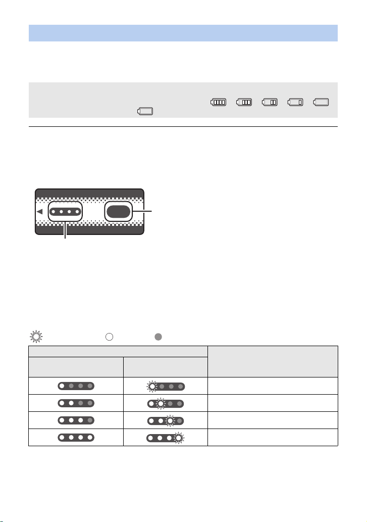
∫ Checking the remaining power using the battery
If you press the CHECK button when charging is not in progress, the indicator (LED lamps) will light
in green so that you can check the remaining power of the battery.
テ
ヤラユヤレ
パ
ヒパパ
A CHECK button
B
Indicator
≥ When the LED lamp does not light up even if you press the CHECK button, the battery is
exhausted. Charge the battery.
How to read the indicator
An approximate guide of the charging progress is indicated by the flashing position of the LED
lamps when charging is in progress. The LED lamps turn off when charging is
complete.
:Flashing in green/ :Lit in green/ :Off
LED lamp status
When checking the
remaining power
During charging
Remaining power of the battery /
Charging progress
0% to 25%
25% to 50%
50% to 75%
75% to 100%
≥ The display of the indicator is an approximate guide. When the battery pack is connected to the
video camera or the charger, refer to the remaining power display of the connected device. The
display of the connected device may differ from that of the battery pack’s indicator.
- 28 -
Page 29
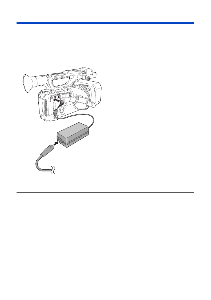
Connecting to the AC outlet
The unit is in the standby condition when the AC adaptor is connected. The primary circuit is always
“live” as long as the AC adaptor is connected to an electrical outlet.
Important:
≥ Use the supplied AC adaptor. Do not use the AC adaptor of another device.
≥ Do not use the AC cable with any other equipment as it is designed only for this unit. Also,
do not use the AC cable from other equipment with this unit.
1 Connect the AC cable to the AC
adaptor and the AC outlet.
2 Connect the AC adaptor to the DC
input terminal [DC IN].
≥ Make sure to set the power switch to OFF and
the status indicator is turned off when
disconnecting the AC adaptor. (l 32)
≥ Insert the plugs as far as they will go.
≥ Even when you use the AC adaptor for recording images, keep the battery connected. This
allows you to continue the recording even if a power failure occurs or the AC adaptor is
unplugged from the AC outlet by accident.
≥ This unit consumes a small amount of power even when turned off. When leaving the product
unused for a long time, disconnect the AC adaptor from the AC outlet for power saving.
- 29 -
Page 30
Preparation
64
Preparation of SD cards
The unit can record motion pictures or still pictures to an SD card.
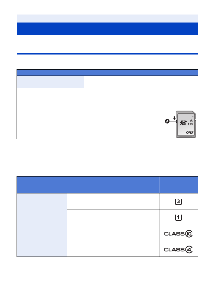
Cards that you can use with this unit
≥ The cards that you can use are correct as of September 2016.
≥ We recommend that you use a Panasonic Memory Card.
Card type Capacity
SDHC Memory Card 4 GB to 32 GB
SDXC Memory Card 48 GB to 128 GB
≥ We do not guarantee the operation of SD cards other than the ones above.
≥ 4 GB or more Memory Cards that do not have the SDHC logo or 48 GB or more Memory Cards
that do not have the SDXC logo are not based on SD Memory Card Specifications.
≥ This unit is compatible with UHS-
≥ When the write-protect switch A on SD card is locked, no recording,
deletion or editing will be possible on the card.
≥ Keep the Memory Card out of reach of children to prevent swallowing.
∫ About the Speed Class ratings for recording motion pictures
≥ Depending on [REC MODE] (l 148) and [REC FORMAT] (l 148), the required card differs.
Use a card that meets the following ratings of the SD Speed Class or UHS Speed Class.
Use of a non-compatible card may cause recording to stop suddenly.
≥ SD Speed Class and UHS Speed Class are the speed standards regarding continuous writing. To
check the class, see the labelled side, etc. of the card.
Recording modes
I UHS Speed Class3 standard SDHC/SDXC Memory Cards.
Recording function
or
Recording format
VFR Mode,
100 Mbps
Speed Class ratings Label examples
UHS Speed Class3
MOV/MP4
50 Mbps
AVCHD All Class4 or more
UHS Speed Class1 or
more
Class10 or more
- 30 -
Page 31

Inserting/removing an SD card
When using an SD card for the first time, it is necessary to format the SD card. (l 43) When the
SD card is formatted, all of the recorded data is deleted. Once the data is deleted, it cannot be
restored.
Caution:
Check that the access lamp has gone off.
Access lamp A
≥ When this unit is accessing the SD card,
the access lamp lights up.
1 Open the SD card slot cover and
insert (remove) the SD card into
(from) the card slot B.
≥ One SD card can be inserted into each of the
card slot 1 and the card slot 2.
≥ Face the terminal side C in the direction
shown in the illustration and press it straight
in as far as it will go.
≥ Press the center of the SD card and then pull
it straight out.
2 Securely close the SD card slot
cover.
≥ Do not touch the terminals on the back of the
SD card.
≥ Do not apply strong shocks, bend, or drop the
SD card.
≥ Electrical noise, static electricity or the failure
of this unit or the SD card may damage or
erase the data stored on the SD card.
≥ When the card access lamp is lit, do not:
j Remove the SD card
j Turn the unit off
j Insert and remove the USB Cable
j Expose the unit to vibrations or shock
Performing the above while the lamp is on
may result in damage to data/SD card or this
unit.
≥ Do not expose the terminals of the SD card to
water, dirt or dust.
≥ Do not place SD cards in the following areas:
j In direct sunlight
j In very dusty or humid areas
j Near a heater
j Locations susceptible to significant
difference in temperature (condensation
can occur.)
j Where static electricity or electromagnetic
waves occur
≥ To protect SD cards, return them to their
cases when you are not using them.
≥ About disposing of or giving away the SD
card. (l 8)
- 31 -
Page 32

Preparation
ON
OFF
Turning the unit on/off
Set the power switch to ON while pressing the lock release button B to turn on
the unit.
To turn off the unit
Set the power switch to OFF while
pressing the lock release button.
The status indicator goes off.
A The status indicator lights on.
≥ To turn on the unit again after the [ECONOMY (BATT)] or [ECONOMY (AC)] is activated, set the
power switch to OFF once, and then to ON again. (l 176)
Preparation
Selecting a mode
Press the THUMBNAIL button to change the mode to Recording Mode or
Playback Mode.
Recording Mode (l 43) The recording screen is displayed. You can record motion
Playback Mode (l 105) The thumbnail screen for playback is displayed. You can play
≥ When you turn on this unit, it starts up in Recording Mode.
≥ If you press the recording start/stop button or sub recording start/stop button in Playback Mode,
the mode will be switched to Recording Mode and recording will start.
pictures.
back motion pictures and still pictures.
A THUMBNAIL button
- 32 -
Page 33

Preparation
Using the LCD monitor/Viewfinder
The viewfinder is turned off and the LCD monitor is turned on when the LCD monitor is extracted.
The viewfinder is turned on when the LCD monitor is retracted.
Switching between the LCD monitor and viewfinder displays
Select the menu. (l 41)
MENU
: [OUTPUT SETUP] # [LCD/EVF OUTPUT] # desired setting
[LCD]: The LCD monitor is turned on when the LCD monitor is extracted. The viewfinder is
[EVF]: The viewfinder turns on. The LCD monitor does not turn on.
not turned on.
∫ To change the setting with a USER button
You can change the settings of the LCD monitor and Viewfinder by registering [LCD/EVF OUTPUT]
to a USER button.
≥ This function is registered to the USER7 button by default.
≥ Please refer to page 80 for details about setting the USER button.
When the recording screen is displayed, press the USER button to which [LCD/
EVF OUTPUT] is registered.
≥ Switches the setting each time the button is pressed.
[LCD]
←→ [EVF]
≥ The setting is also applied to the [LCD/EVF OUTPUT] menu setting.
≥ [LCD] will be selected when the LCD monitor is extracted.
- 33 -
Page 34

Using the LCD monitor
270°
1 Extract the LCD monitor in the
direction as indicated in the figure.
≥ Hold the LCD monitor extract part A, and
extract the LCD monitor until it clicks into
position.
2 Rotate to the position that is easy
to view.
To retract the LCD monitor
Retract as shown in the figure with the LCD facing
downward.
Range of rotation of the LCD monitor
≥ It can rotate up to 270o towards the lens.
- 34 -
Page 35

How to use the touch screen
You can operate by directly touching the LCD monitor (touch screen) with your finger.
∫ Touch
Touch and release the touch screen to select icon or
picture.
≥ Touch the center of the icon.
≥ Touching the touch screen will not operate while you
are touching another part of the touch screen.
∫ Slide while touching
Move your finger while pressing on the touch screen.
∫ About the operation icons
///:
Touch when changing a page or performing settings.
≥ Do not touch the LCD monitor with hard pointed tips, such as ball point pens.
- 35 -
Page 36

LCD monitor adjustment
MENU
≥ These settings will not affect the images actually recorded.
[POWER LCD]
This makes it easier to view the LCD monitor in bright places including outdoors.
Select the menu. (l 41)
MENU
: [DISP SETUP] # [POWER LCD] #
[+1] (Makes brighter)/[0] (Normal)/[-1] (Makes less bright)
≥ When the AC adaptor is in use, [POWER LCD] is set to [+1] automatically.
≥ [0] is selected when:
j [USB MODE SELECT] is set to [DEVICE] and this unit is connected to a PC. (l 122)
≥ This item is not available while the LCD monitor is turned off.
[LCD SET]
It adjusts brightness and color density on the LCD monitor.
1 Select the menu. (l 41)
: [DISP SETUP] # [LCD SET]
2 Touch the desired setting item.
[COLOR]: Color level of the LCD monitor
[BRIGHTNESS]: Brightness of the LCD monitor
[CONTRAST]: Contrast of the LCD monitor
3 Touch / to adjust settings.
≥ You can select a value between s16 and r16.
4 Touch [RETURN].
≥ Touch [EXIT] to exit the menu screen.
≥ This item is not available while the LCD monitor is turned off.
- 36 -
Page 37

Viewfinder adjustment
≥ These settings will not affect the images actually recorded.
Adjusting the field of view
It adjusts the field of view to show the image on the viewfinder clearly.
1 Adjust the viewfinder to suit your vision so
that you can see the display images clearly.
≥ Be careful not to trap your fingers when moving the
viewfinder.
≥ The viewfinder can be lifted vertically up to
approximately 90o.
≥ Retract the LCD monitor and turn on the viewfinder.
2 Adjust the focus by operating the eyepiece
corrector lever.
A Eyepiece corrector lever
[EVF SETTING]
It adjusts brightness and color density of the viewfinder.
≥ Use the jog dial to change the settings. (l 102)
1 Select the menu. (l 41)
MENU
: [DISP SETUP] # [EVF SETTING] # desired setting
[COLOR]: Color level of the viewfinder
[BRIGHTNESS]: Brightness of the viewfinder
[CONTRAST]: Contrast of the viewfinder
2 Rotate the jog dial to move the cursor to the
value display A.
≥ Push the jog dial to select the value display.
3 Rotate the jog dial to adjust the setting.
≥ Pushing the jog dial will set the value you have selected.
≥ You can select a value between s16 and r16.
4 Select [RETURN].
≥ Select [EXIT].
≥ This item is not available while the viewfinder is turned off.
≥ When [COLOR] is set to s16, images are displayed in black and white.
- 37 -
Page 38

[EVF COLOR]
The recording images or playback images on the viewfinder can be selected between color/black
and white.
Select the menu. (l 41)
MENU
: [DISP SETUP] # [EVF COLOR]# [ON] or [OFF]
[ON]: Displayed in color
[OFF]: Displayed in black and white
≥ If you adjust the [COLOR] setting in [EVF SETTING], [EVF COLOR] will be set to [ON].
Recording yourself
≥ Change the mode to Recording Mode. (l 32)
Rotate the LCD monitor towards the lens side.
≥ Displaying during the recording yourself can be
switched by setting [SELF SHOOT]. (l 174)
≥ Only some indications will appear on the screen when the [SELF SHOOT] is set to [MIRROR].
When appears, return the direction of the LCD monitor to normal position and check the
warning/alarm indication. (l 185)
≥ When the viewfinder is turned up, the LCD monitor is turned off.
- 38 -
Page 39

Preparation
Setting date and time
When this unit is turned on, the message [SET TIME ZONE AND DATE/TIME] may appear.
To make these settings, select [YES], and follow the instructions from Step 2-3 of the time zone
setting procedure.
Time zone
Time difference from the Greenwich Mean Time can be set.
1 Select the menu. (l 41)
MENU
: [OTHER FUNCTION] # [TIME ZONE]
2 Touch / and set the region to record.
3 Touch [EXIT] to complete the setting.
≥ If the [CLOCK SET] screen appears, perform [CLOCK SET].
≥ When the time zone setting is changed, the date/time setting of the unit also changes
automatically.
Clock setting
1 Select the menu. (l 41)
MENU
: [OTHER FUNCTION] # [CLOCK SET]
2 Touch the date or time to be set, then set the
desired value using / .
≥ The year can be set between 2000 and 2039.
3 Touch [EXIT] to complete the setting.
≥ The date and time function is driven by a built-in lithium battery.
≥ If the time display becomes [- -], the built-in lithium battery needs to be charged. To recharge the
built-in lithium battery, connect the AC adaptor or attach a charged battery to this unit. Leave the
unit as it is for approx. 24 hours and the battery will maintain the date and time for approx.
6 months. (The battery is still being recharged even if the unit is off.)
≥ The way that time is displayed can be changed in the menu settings. (l 172)
[DISP SETUP] # [DATE/TIME] or [DATE FORMAT]
- 39 -
Page 40

∫ Time zone table
Time
difference
0:00 London, Casablanca r3:30 Tehran
s1:00 Azores r4:00 Dubai, Abu Dhabi
s2:00 Fernando de Noronha r4:30 Kabul
s3:00
s3:30
s4:00 Manaus, La Paz r5:45 Kathmandu
s4:30 Caracas r6:00 Dhaka
s5:00 Toronto, New York, Miami, Lima r6:30 Yangon
s6:00 Chicago, Houston, Mexico City r7:00 Bangkok, Jakarta
s7:00
s8:00 Vancouver, Seattle, Los Angeles r9:00 Seoul, Tokyo
s9:00 Alaska, Anchorage r9:30 Adelaide
s10:00 Hawaii, Honolulu, Tahiti r10:00 Guam, Sydney
s11:00 Midway Islands r11: 00 Solomon Islands, New Caledonia
r1:00 Berlin, Paris, Rome, Madrid r12:00 Fiji, Auckland, Wellington
r2:00
r3:00
Rio de Janeiro, Sao Paulo,
Buenos Aires
Newfoundland
Denver, Phoenix
Helsinki, Athens, Cairo,
Johannesburg
M
oscow, Kuwait, Riyadh, Nairobi
Region
Time
difference
r5:00
r5:30
r8:00
r12:45
Region
Islamabad, Karachi, Male
Delhi, Kolkata, Mumbai, Chennai,
Colombo
Beijing, Hong Kong, Kuala
Lumpur, Singapore
Chatham Islands
- 40 -
Page 41

Preparation
MENU
Using the menu screen
≥ You can also select menu items by operating the jog dial. (l 102)
MENU
1 Press the MENU button .
2 Touch the top menu A.
3 Touch the submenu B.
≥ Next (Previous) page can be displayed by touching /
.
4 Touch the desired item to enter the setting.
5 Touch [EXIT] to exit the menu setting.
- 41 -
Page 42

Recording
Before recording
≥
When recording, make sure your footing is stable and there is no danger of colliding with another person or object.
≥ Hold the eye cup of the viewfinder as close as possible to your eye.
≥ Adjust the angle of the LCD monitor according to the position in which the unit is held.
≥ When you are outdoors, record pictures with the sunlight behind you. If the subject is backlit, it will
become dark in the recording.
≥ Keep your arms near your body and separate your legs for better balance.
≥ For stable images, it is recommended to use a tripod whenever possible.
Recording
Selecting a media to record
You can specify the card slot to which motion pictures are to be recorded.
Select the menu.
MENU
: [RECORD SETUP] # [MEDIA SELECT] # [SD CARD 1]/[SD CARD 2]
≥ In the following situation, if you start recording with normal settings or start recording when [2
SLOTS FUNC.] (l 162) is set to [RELAY REC], the card slot used for motion picture recording
will be switched automatically:
j An SD card is not inserted to the card slot selected in [MEDIA SELECT], or the SD card in the
selected card slot is full when there is another SD card in the other slot.
≥
You can also change the card slot used for motion picture recording by pressing the USER button to which
[SLOT SEL] is registered or touching the applicable USER button icon while recording is paused.
(l 80)
- 42 -
Page 43

Formatting media
If you use the SD cards for the first time for recording with this unit, format the cards.
Please be aware that if a medium is formatted, then all the data recorded on the medium will be
erased and cannot be restored. Back up important data on a PC etc. (l 122)
≥ When using two SD cards, format both SD cards.
1 Select the menu.
MENU
: [OTHER FUNCTION] # [FORMAT MEDIA]
2 Touch [SD CARD 1] or [SD CARD 2].
≥ When formatting is complete, touch [EXIT] to exit the message screen.
≥ Do not turn this unit off or remove the SD card, while formatting. Do not expose the unit to
vibrations or shock.
Use this unit to format media.
Do not format an SD card using any other equipment such as a PC. Otherwise it may not
be possible to use the card on this unit.
Recording
Recording motion picture
≥ Before turning on this unit, open the lens cover. (l 21)
1 Change the mode to
Recording Mode. (l 32)
≥ Extract the LCD monitor.
2 Press the recording start/
stop button B to start
recording.
≥ Recording will stop when you press
the recording start/stop button again.
REC
OFF
ON
A When you begin recording, REC (red) is
displayed.
- 43 -
Page 44

∫ Screen indications in the Recording Mode
TC 00:00:00.0000
59.94
p
50M
R 1h20m
R 1h20m
MAIN
MAIN
TC 00:00:00
TC 00:00:00.00
TC 00:00:00.00 Counter display (l 76)
* Displayed only during normal recording.
≥ To change the recording method, change [REC MODE] or [REC FORMAT]. (l 148)
≥ The images recorded between pressing the recording start/stop button to start recording and
pressing it again to pause recording become one scene.
≥
When the file size of a r ecorded scene exceeds one of the following sizes or the recording time exceeds
one of the following lengths of time, the scene will be divided automatically. (Recording continues.)
≥ (Maximum recordable scenes of a single SD card)
≥ When the SD card contains scenes recorded with [REC MODE] set to [MOV]/[MP4] and still
pictures, the maximum recordable scenes and the maximum recordable scenes on each date will
be smaller than those in the table above.
≥ Number of scenes that can be recorded will be less than above in following cases:
j If you change [REC FORMAT] (l 148)
j When [2 SLOTS FUNC.] is set to [SIMULTANEOUS] (l 162)
j During the Interval Recording (l 163)
≥ Please refer to page 201 about approximate recordable time.
MAIN
R 1h20m
R 1h20m
R 1h20m
R 1h20m
50M
59.94
p
/
Card slot number
(White)
R1h20m Approximate remaining recordable time
≥ When the remaining time is less than 1 minute, R 0h00m flashes red.
Card slot selected for motion picture recording (l 42)*
Recording format (l 148)
50M Bit rate (l 148)
Recording mode (l 148)
59.94p Frame rate (l 148)
AVCHD scene Approximately 4 GB
MOV/MP4 scene (when using an SDHC Memory Card) Approximately
4 GB or 30 minutes
MOV/MP4 scene (when using an SDXC Memory Card) Approximately
96 GB or 3 hours
Recording mode MOV/MP4 AVCHD
Recordable scenes Approx. 89100 Approx. 3900
Different dates (l 112) Approx. 900 Approx. 900
- 44 -
Page 45

Recording
MENU
Switching between Auto and Manual Mode
MANU
AUTO/MANU switch
Slide the switch to change Auto Mode/Manual
Mode.
≥ is displayed in the Auto Mode.
∫ Auto Mode
In Auto Mode, this unit operates according to the [AUTO SW] menu settings.
≥ When the following settings are automatically adjusted in Auto Mode, the corresponding Manual
Mode settings are canceled:
j Focus (l 53)
j Iris (l 65)
∫ To enable/disable auto switch functions
You can enable/disable functions that are automatically adjusted in Auto Mode.
Select the menu.
: [AUTO SW] # desired setting
Menu item Setting
[ON]: Activates Auto Iris in Auto Mode.
[A.IRIS]
[AGC]
[AUTO SHUTTER]
[ATW]
[OFF]: Activates Auto Iris as a manual mode. Use the IRIS button to
switch between Auto Iris Mode and Manual Iris Mode.
[ON]: Activates Auto Gain in Auto Mode.
[OFF]: Activates Auto Gain as a manual mode. The gain is adjusted
according to the settings assigned to the GAIN button.
[ON]: Activates Auto Shutter in Auto Mode.
[OFF]: Activates Auto Shutter as a manual mode. Press the SHUTTER
button to switch between Auto Shutter Mode and Manual
Shutter Mode.
[ON]: Activates Auto Tracking White Balance in Auto Mode.
[OFF]: Activates Auto Tracking White Balance as a manual mode. The
white balance is adjusted according to the setting registered to
the WHITE BAL button. (l 61)
j GAIN (l 67)
j Shutter speed (l 70)
- 45 -
Page 46

Menu item Setting
[ON]: Activates Auto Focus in Auto Mode.
[AF]
[OFF]: Activates Auto Focus as a manual mode. Focus is adjusted
according to the functions of the FOCUS A/M/¶ switch.
Automatic Tracking White Balance
The Auto Tracking White (ATW) Balance function of this unit automatically adjusts the White
Balance according to the lighting condition.
If Auto Tracking White Balance does not work correctly, switch to Manual Mode first, and then adjust
the White Balance. (l 61)
Auto Focus
The unit focuses automatically.
≥ Auto Focus does not work correctly in the following situations. Record pictures in the Manual
Focus Mode. (l 53)
j Recording distant and close-up objects at the same time
j Recording a subject behind dirty or dusty window
j Recording a subject that is surrounded by objects with glossy surfaces or by highly reflective
objects
∫ Controls that are disabled in Auto Mode
Certain controls of this unit may be disabled in Auto Mode. Controls to be disabled vary by the
[AUTO SW] menu settings.
Conditions that disable controls Controls that are disabled in Auto Mode
[A.IRIS] is set to [ON]. Iris Ring, IRIS button
[AGC] is set to [ON]. GAIN button, the USER button to which [SUPER GAIN]
[AUTO SHUTTER] is set to [ON]. SHUTTER button
[ATW] is set to [ON]. WHITE BAL button
[AF] is set to [ON]. Focus ring, FOCUS ASSIST button, FOCUS A/M/
is registered
switch, PUSH AUTO button, the USER button to which
[FOCUS ASSIST 1], [FOCUS ASSIST 2] or
[PUSH AUTO] is registered
- 46 -
Page 47

Recording
Adjusting the Picture Quality
You can set the picture quality of images to be recorded in the main menu # [SCENE FILE].
Detail function
This function thickens or weakens the outlines of images. It effectively softens or sharpens images,
but in some cases, the whole image may become rough due to emphasized noise and edges. To
avoid such problems, it is necessary not to add this effect on parts where emphasizing is not
needed and keep the details of the parts.
∫ Menu item
[MASTER DETAIL]: Adjusts the degree of overall outline correction in images. (l 141)
[DETAIL CORING]: Adjusts the detail noise removal level. (l 141)
[SKIN TONE DTL]: Makes skin colors appear softer for a more attractive appearance. (l 142)
[V DETAIL LEVEL]: Adjusts the degree of vertical outline correction in images. (l 142)
Skin tone function
This function makes human skin look smoother in images.
∫ Menu item
[SKIN TONE DTL] (l 142)
RB gain control function
When the White Balance mode is set to [Ach] or [Bch], this function enhances or reduces the
intensity of red and blue. It works in combination with Auto White Balance.
≥ It does not work when the White Balance mode is set to [ATW], [P3200K], [P5600K], or [VAR].
∫ Menu item
[RB GAIN CONTROL SETTING] (l 143)
Chroma setting function
This function sets color saturation and phase. It applies effects on whole images. It cannot be set to
individual color hue.
∫ Menu item
[CHROMA LEVEL]: Adjusts the color density. (l 144)
[CHROMA PHASE]: Adjusts the color balance. (l 144)
- 47 -
Page 48

Black control function
This function sets the black level that is to be the reference of luminance.
∫ Menu item
[MASTER PED] (l 144)
Gamma function
This function optimizes the tone of images.
∫ Menu item
[GAMMA MODE]: Sets the optimal tone and contrast of images for the scene to be
[BLACK GAMMA]: Sets the gamma curve for dark areas.(l 145)
recorded. (l 145)
Knee function
This function sets the compression of video signals to prevent white saturation in images.
∫ Menu item
[KNEE MODE]: Sets the compression level of highly bright image signals
[KNEE MASTER POINT]: Adjusts the knee point position in 0.5% steps. (l 146)
[KNEE MASTER SLOPE]: Sets the knee inclination. (l 146)
received by the image sensor to minimize white saturation.
(l 146)
- 48 -
Page 49

Recording
TT
WW
WW
TT
WW
ABA
B
Using the zoom
The unit can deliver a maximum optical zoom of 15k.
≥ (When the picture size of [REC FORMAT] (l 148) is 1920k1080 or below)
It can zoom up to approx. 25k when the [i.Zoom] is set to [ON]. (l 94)
≥ You can check the zoom magnification on-screen, displayed as a value between Z00 and Z99.
The value gets larger as you zoom in, and smaller as you zoom out.
≥ You can change the unit of the on-screen zoom magnification display by changing the [ZOOM
DISPLAY] setting in the [DISP SETUP] menu. You can also change the setting so that the onscreen display does not appear. (l 172)
≥ When [FOCUS MACRO] is set to [OFF], subjects at a distance of approximately 1.0 m (3.3 feet)
to infinity can be brought into focus. When [FOCUS MACRO] is set to [ON] and the zoom position
is at the W end, subjects at a distance of approximately 10 cm (3.93 q) to infinity can be brought
into focus. (l 90, 157)
Zoom lever 1/Sub zoom lever 2
T side:
Close-up recording (zoom in)
W side:
Wide-angle recording (zoom out)
Zoom ring 3
A side:
Wide-angle recording (zoom out)
B side:
Close-up recording (zoom in)
≥ If you take your finger off the zoom lever during zoom operation, the operation sound may be
recorded. When returning the zoom lever to the original position, move it quietly.
≥ The zoom magnification is maintained even after this unit is turned off.
- 49 -
Page 50

Using the i.Zoom
MENU
MENU
When [i.Zoom] is set to [ON], you can zoom in while maintaining the beauty of high-definition picture
quality up to a magnification of approx. 25k.
≥ Set [REC FORMAT] to a setting with a picture size of 1920k1080 or below. (l 148)
Select the menu.
: [SW SETUP] # [i.Zoom] # [ON]
≥ You can also use i.Zoom by registering [i.ZOOM] to a USER button. (l 94)
≥ The zoom magnification display will change.
(Example)
j iZ00 to iZ99: magnification levels that fall in the optical zoom range
j Z99: i.Zoom
≥ This function is not available in the following cases:
j In Variable Frame Rate Mode (l 92)
j When [REC FORMAT] is set to a setting with a size of UHD (3840k2160)
j During Freeze Frame (l 87)
Using Fast Zoom
When [FAST ZOOM] is set to [ON], you can use Fast Zoom while operating the zoom with the zoom
lever.
1 Select the menu.
: [SW SETUP] # [FAST ZOOM] # [ON]
2 Push the zoom lever fully to operate the zoom.
≥ The zoom magnification display changes when using Fast Zoom. (Example: 99)
∫ About the zoom speed
≥ The zoom speed will vary depending on how far the zoom lever is pressed or how fast the zoom
ring is rotated.
≥ The zoom operation using the sub zoom lever will be performed at a constant speed. Zoom
speed of the sub zoom lever will vary depending on the setting of [SUB ZOOM]. (l 159)
≥ You can also use Fast Zoom by registering [FAST ZOOM] to a USER button. (l 80)
≥ The sound of the zoom mechanism becomes louder than usual during fast zoom operation. This
may cause the sound to be recorded during recording.
≥ Depending on the subject, Auto Focus may not track it when Fast Zoom is in use.
Utilizing the USER button
Digital zoom can be used by setting the USER button. (l 85)
≥ Please refer to page 80 for details about setting the USER button.
- 50 -
Page 51

Recording
MENU
MENU
Image Stabilizer Function
Use the Image Stabilizer to reduce the effects of shake during recording.
This unit is equipped with Hybrid Optical Image Stabilizer.
Hybrid Optical Image Stabilizer is a hybrid of Optical and Electrical Image Stabilizer.
1 Register [O.I.S.] to a USER button. (l 80)
≥ This function is registered to the USER6 button by default.
2 Press the USER button to which [O.I.S.] is registered or touch the applicable
USER button icon to switch the Image Stabilizer on/off.
/ # (OFF)
≥ You can also access this function by selecting menu items.
[SW SETUP] # [O.I.S.] # [ON]/[OFF]
≥ When [HYBRID O.I.S.] is [ON], is displayed. When [OFF], is displayed.
≥ This item cannot be set during Freeze Frame (l 87)
∫ Changing Image Stabilizer Mode
Select the menu.
: [SW SETUP] # [HYBRID O.I.S.] # [ON] or [OFF]
When set to [ON], you can further improve image stabilization for holding the unit and recording a
distant subject with zoom.
≥ Optical Image Stabilizer will be disabled and the setting cannot be changed in the following
cases:
j When Optical Image Stabilizer is set to (setting canceled)
j When the size is set to UHD (3840k2160) in [REC FORMAT] (l 148)
j In Variable Frame Rate Mode (l 92)
≥ The setting cannot be changed during Freeze Frame (l 87)
≥ Stabilization may not be possible under strong shaking conditions.
≥ When using a tripod, we recommend that you set the Image Stabilizer to (setting canceled).
Customizing the Image Stabilizer for various recording conditions
You can customize the Image Stabilizer by adjusting the [BLUR AMPLITUDE] and [BLUR
FREQUENCY] settings individually.
∫ Custom Optical Image Stabilizer
When [ON] is selected, the Image Stabilizer works with customized [BLUR AMPLITUDE] and
[BLUR FREQUENCY] settings.
Select the menu.
: [SW SETUP] # [CUSTOM O.I.S.] # [ON]
- 51 -
Page 52

∫ Blur amplitude
MENU
MENU
You can adjust the performance of camera shake correction according to the level of camera shake
during recording.
Select the menu.
: [SW SETUP] # [BLUR AMPLITUDE] # desired setting
[1]/[2]/[3]/[4]/[5]
≥ If you set a smaller value, correction performance against minor camera shake will be enhanced.
Even though smaller values allow more effective screen stabilization in situations with minor
camera shake, such as when you are recording from a fixed position, they are less effective for
correcting significant camera shake. We recommend setting a smaller value when you keep
recording the same subject, for example.
≥ If you set a larger value, camera shake of varying degrees ranging from minor to significant will
be corrected in a balanced manner. Although larger values allow you to correct significant camera
shake more effectively, the screen becomes unstable when you are recording from a fixed
position. We recommend that you set a larger value in situations where images are expected to
be quite blurry, such as when recording in an unstable position.
∫ Blur frequency
You can change the target frequency range for camera shake correction to adjust its performance
according to the recording style.
Select the menu.
: [SW SETUP] # [BLUR FREQUENCY] # desired setting
[1]: This enhances the correction performance against camera shake of varying degrees, ranging
from slow camera shake that falls in the low frequency range to fast and subtle camera shake
that falls in the high frequency range. We recommend that you select this setting when
recording a subject from a fixed position without panning or tilting this unit.
[2]: This is a standard setting which enhances the correction performance against camera shake
that falls in the average-to-high frequency range. Even while adjusting the position of this
unit, you can keep the resulting motion in the image look natural and maintain the correction
performance.
[3]: This mainly enhances the correction performance against fast and subtle camera shake that
falls in the high frequency range while weakening the correction performance against slow
camera shake that falls in the low frequency range. We recommend that you use this setting
when panning or tilting this unit many times while recording.
- 52 -
Page 53

Recording
Focus
Perform focus adjustments using the focus ring. If auto focusing is difficult due to the conditions,
then use Manual Focus.
A FOCUS A/M/¶ switch
FOCUS
M
∞
B PUSH AUTO button
C Focus ring
A
≥ Switch to Manual Mode. (l 45)
PUSH AUTO
1 Set the FOCUS A/M/¶ switch to [M] to enable Manual Focus.
≥ It will switch to MF from AF.
2 Adjust the focus by rotating the focus ring.
≥ The focus value can be set from MF00 (Focus distance*: approximately 10.0 cm (3.93 q) [When
[FOCUS MACRO] (l 90, 157) is set to [ON]]) to MF99 (Focus distance
focus value gets, the further the position where focus is achieved.
* Focus distance refers to the minimum distance where a subject can be brought into focus.
≥ If you move the FOCUS A/M/¶ switch towards [¶], focus will be adjusted to MF95 on the infinity
side. (The FOCUS A/M/¶ switch will return to the [M] position.)
≥ To return to Auto Focus, set the FOCUS A/M/¶ switch to [A], or set [AF] to [ON] and switch to
Auto Mode. (l 45)
≥ If you set [FOCUS MACRO] to [ON], when the distance to the subject approaches within 0.95 m
(3.12 feet) approx., the unit switches to the macro range and or . (The unit may switch to
the macro range even when the distance to the subject is 0.95 m (3.12 feet) or more depending
on the subject.)
≥ Depending on the zoom magnification, this unit may fail to switch to the macro range, or go to a
non-displayed focus value.
≥ When you perform a zoom operation in the macro range, this unit may go out of focus.
≥ When [AF] is set to [ON] and this unit is set to Auto Mode, auto focusing is performed regardless
of the position of FOCUS A/M/¶ switch. (l 45)
≥ The unit of the focus value display varies depending on the [FOCUS DISPLAY] setting in the
[DISP SETUP] menu. You can also change the setting so that the on-screen display does not
appear. (l 172)
*
: infinity). The larger the
- 53 -
Page 54

∫ To change the way you adjust focus with the focus ring
MENU
MENU
MENU
MENU
Select the menu.
: [SW SETUP] #
[FOCUS RING DRIVE]
[SPEED]: Adjusts the focus value according to the speed at which the focus ring is
[COARSE]: Adjusts the focus value according to the rotational position of the focus
[FINE]: Adjusts the focus value according to the rotational position of the focus
rotated.
ring. Since the operation of the focus ring results in a greater change in
focus value, this setting is suitable for making rough adjustments.
ring. Since the operation of the focus ring results in a smaller change in
focus value, this setting is suitable for making fine adjustments.
∫ To emphasize the outline of images
Setting [EVF/LCD DETAIL] to [ON] helps you achieve focus easier by emphasizing the outlines of
an image displayed on the LCD monitor and viewfinder.
You can also adjust the emphasis level or change the frequency.
≥ You can also enable or disable this function with the applicable USER button. (l 90)
≥ These settings will not affect the images actually recorded.
: [DISP SETUP] # [EVF/LCD DETAIL] # [ON]
Adjusting the level of [EVF/LCD DETAIL]
1 Select the menu.
: [DISP SETUP] # [EVF/LCD PEAK LEVEL]
2 Touch / to adjust settings.
≥ You can select a value between s3 and r3.
3 Touch [EXIT] to complete the setting.
Setting the peaking frequency of [EVF/LCD DETAIL]
Select the menu.
: [DISP SETUP] # [EVF/LCD PEAK FREQ.] # [HIGH] or [LOW]
≥ [EVF/LCD DETAIL] is canceled in following cases:
j If you use Focus Assist (peaking) (l 57)
- 54 -
Page 55

Customizing Auto Focus for various recording conditions
MENU
MENU
MENU
You can customize Auto Focus for various recording conditions by adjusting the settings of [AF
SPEED], [AF SENSITIVITY], and [AF AREA WIDTH] individually.
∫ Custom AF function
When [ON] is selected, Auto Focus works with customized [AF SPEED] and [AF SENSITIVITY]
settings.
≥ Switch to Auto Focus Mode. (l 53)
Select the menu.
: [SW SETUP] # [CUSTOM AF] # [ON]
∫ AF speed setup
You can change the focus speed of Auto Focus.
≥ Switch to Auto Focus Mode. (l 53)
≥ Set [CUSTOM AF] to [ON].
1 Select the menu.
: [SW SETUP] #
[AF SPEED]
2 Touch / to adjust settings.
≥ You can select a value between j5 and i5.
≥ The larger the value is, the faster the focus speed will become. Conversely, the smaller the value
is, the slower the focus speed will become.
3 Touch [EXIT] to complete the setting.
∫ AF Sensitivity setup
You can enhance the stability or tracking performance of Auto Focus.
≥ Switch to Auto Focus Mode. (l 53)
≥ Set [CUSTOM AF] to [ON].
1 Select the menu.
: [SW SETUP] # [AF SENSITIVITY]
2 Touch / to adjust settings.
≥ You can select a value between 0 and 10.
≥ Setting a larger value will enhance the tracking performance of focus, making it easier to move
focus between subjects at varying distances from this unit. We recommend that you set a larger
value to keep focus on a fast-moving subject.
≥ Setting a smaller value will provide more stability to focus, making it easier to keep focus on the
targeted subject even when an intervening object passes in front of the camera or the subject
disappears from the view of this unit. We recommend that you set a smaller value to avoid
bringing an intervening object or the background into focus.
3 Touch [EXIT] to complete the setting.
≥ This function is not available in the following cases:
j In manual focus mode (l 53)
j In Variable Frame Rate Mode (l 92)
≥ When a faster [AF SPEED] value is selected, focus mechanism noise will be more audible. As a
result, the noise may be recorded while recording is in progress.
- 55 -
Page 56

∫ AF Area Width adjustment
MENU
AF-AREA
You can adjust the effective area width for Auto Focus according to the size of the subject.
≥ Switch to Auto Focus Mode. (l 53)
1 Select the menu.
: [SW SETUP] # [AF AREA WIDTH] # [SET]
2 Push the jog dial.
3 Rotate the jog dial to adjust the AF area
frame.
A [RETURN]
B AF area frame
C [EXIT]
4 Touch [EXIT] to complete the setting.
≥ will be displayed on the screen.
≥ To cancel the settings, set [AF AREA WIDTH] to [OFF].
≥ If you push the jog dial in Step 2, the AF area frame turns yellow, allowing you to select
[RETURN]/[EXIT] by rotating the jog dial. Push the jog dial to set the selected item.
≥ You can also adjust AF area width by registering [AF AREA] to a USER button. (l 97)
≥ This function is not available in the following cases:
j In manual focus mode (l 53)
j When using Area Mode (l 88)
j During Freeze Frame (l 87)
One Push AF
If you press the PUSH AUTO button in Manual Focus Mode, the camera performs high-speed
focusing until the image is focused.
≥ Switch to Manual Focus Mode. (l 53)
Press PUSH AUTO button.
≥ Auto Focus will be activated and the camera will perform high-speed focusing until the image is
focused.
≥ The focus setting returns to Manual Focus Mode once the image is focused or a certain time has
elapsed.
≥ You can also use One Push AF with the USER button to which [PUSH AUTO] is registered.
(l 80)
≥ One Push AF does not work in following cases:
j When Auto Focus is used
- 56 -
Page 57

Push AF
MENU
MENU
If you press and hold the PUSH AUTO button, Manual Focus will be temporarily switched to Auto
Focus.
≥ Set this unit to Manual Focus. (l 53)
Press and hold the PUSH AUTO button.
≥ The focus position will be automatically adjusted for the subject at the center of the screen.
≥ If you set [AREA MODE] to [FOCUS], [FOCUS/IRIS] or [FOCUS/Y GET] and use Area Mode, the
focus position will be automatically adjusted to the subject you have touched. (l 88)
≥ It will be canceled when the button is released, and the focus position set by the Push AF will be
maintained.
≥ You can also use Push AF with the USER button to which [PUSH AUTO] is registered. (l 80)
≥ Push AF does not work in following cases:
j When Auto Focus is used
Focus Assist
You can use Focus Assist by pressing the FOCUS ASSIST button or the USER button to which
[FOCUS ASSIST 1] or [FOCUS ASSIST 2] is registered.
≥ For information on how to set the USER buttons, refer to page 80.
Selecting a Focus Assist method
∫ To select the Focus Assist method for the FOCUS ASSIST button or
the USER button to which [FOCUS ASSIST 1] is registered
Select the menu.
: [SW SETUP] # [FOCUS ASSIST 1] # desired setting
[EXPAND]: Magnifies the central area of the screen when Focus Assist is used.
[PEAKING]: Highlights in-focus portions with color when Focus Assist is used.
[BOTH]: Sets both [EXPAND] and [PEAKING].
∫ To select the Focus Assist method for the USER button to which
[FOCUS ASSIST 2] is registered
Select the menu.
: [SW SETUP] # [FOCUS ASSIST 2] # desired setting
[EXPAND] / [PEAKING]
≥ You can use the magnified display and the peaking function separately or use them in
combination by selecting different settings for [FOCUS ASSIST 1] and [FOCUS ASSIST 2].
≥ If [FOCUS ASSIST 1] is set to [BOTH], [FOCUS ASSIST 2] is not available. In addition, the USER
button to which [FOCUS ASSIST 2] is registered is disabled.
- 57 -
Page 58

Using Focus Assist
FOCUS
ASSIST
x3.0
x5.5
≥ Switch to Manual Focus Mode. (l 53)
Press the FOCUS ASSIST button or the USER button
to which [FOCUS ASSIST 1] or [FOCUS ASSIST 2] is
registered.
≥ You can also use Focus Assist by touching the
icon to which [FOCUS ASSIST 1] or [FOCUS ASSIST 2] is
registered.
≥ To turn off Focus Assist, perform the following operations:
j Press the FOCUS ASSIST button or the USER button again,
or touch the USER button icon again.
j Touch [EXIT].
USER
button
∫ To adjust the magnified display
If you set Focus Assist to ON by following either of the procedures below, the central area of the
screen will be magnified. You can change the magnification and position of the magnified display.
j Setting the menu item [FOCUS ASSIST 1] to [EXPAND] or [BOTH] and pressing the FOCUS
ASSIST button or the USER button to which [FOCUS ASSIST 1] is registered.
j Setting the menu item [FOCUS ASSIST 2] to [EXPAND] and pressing the USER button to
which [FOCUS ASSIST 2] is registered.
≥ You can also change the magnification level of the magnified display using the jog dial.
x3.0x3.0
x5.5x5.5
A 3k–5k display
B
5.5k–10k display
C [ASSIST]
D Magnified display
ヴユロバ
ヱヶヴラ
ヴユヵ
E [EXIT]
F Jog dial
(To change the magnification level)
Touch / or rotate the jog dial to change the magnification level.
: Increases the magnification level by 0.5k.
: Decreases the magnification level by 0.5k.
≥ You can adjust the magnification from 3k to 10k.
(Moving the magnified area)
Touch / / / or slide the screen while touching it to move the magnified
area.
- 58 -
Page 59

∫ To change the peaking settings
MENU
MENU
If you set Focus Assist to ON by following either of the
procedures below, in-focus portions are highlighted with
color (peaking).
j Setting the menu item [FOCUS ASSIST 1] to
[PEAKING] or [BOTH] and pressing the FOCUS
ASSIST button or the USER button to which [FOCUS ASSIST 1] is registered.
j Setting the menu item [FOCUS ASSIST 2] to [PEAKING] and pressing the USER button to
which [FOCUS ASSIST 2] is registered.
G: Peaking
≥ You can set the peaking color and strength.
(When changing the peaking color)
Select the menu.
: [SW SETUP] # [PEAKING COLOR] # desired color
[Red]/[Blue]/[Yellow]/[White]
(When setting the peaking strength)
1 Select the menu.
: [SW SETUP] # [PEAKING LEVEL] # desired setting
2 Touch / to adjust settings.
≥ You can select a value between s7 and r7.
3 Touch [EXIT] to complete the setting.
(Notes on Focus Assist)
≥ Focus Assist is not possible in following cases:
j During Recording Check (l 86)
j During Freeze Frame (l 87)
j When color bars are displayed (l 99)
≥ Focus Assist is canceled in following cases:
j If you turn the unit off
j (If you operate the FOCUS ASSIST button or the USER button to which [FOCUS ASSIST 1] is
registered)
When the setting of [FOCUS ASSIST 1] (l 58) is changed
j (If you operate the USER button to which [FOCUS ASSIST 2] is registered)
When the setting of [FOCUS ASSIST 2] (l 58) is changed
j When you set this unit to Auto Focus
≥ The magnified display and peaking are not displayed on recorded images.
≥ The magnified display and peaking are not displayed on an external monitor.
≥ Freeze Frame is not available when you use Focus Assist. (l 87)
≥ Peaking may not be displayed when you use Digital Zoom (l 85). To zoom in and use peaking at
the same time, we recommend increasing the magnification level of the magnified display by
setting [FOCUS ASSIST 1] to [BOTH] or by using the magnified display and the peaking function
in combination.
- 59 -
Page 60

(Notes on the peaking of Focus Assist)
≥ When EVF/LCD detail is enabled, Focus Assist is canceled. (l 54)
(Notes on the magnified display of Focus Assist)
≥ Some information on the screen disappears when the screen is magnified.
≥ In the following cases, the screen is not magnified during Focus Assist:
j During motion picture recording or PRE-REC (l 92, 165)
j When using Digital Zoom
j When using Area Mode (l 88)
j During auto recording (l 96)
j In Variable Frame Rate Mode (l 92)
j During AG ROP application connection (l 131)
≥ If you set the magnification level of the magnified display to 5.5k or higher, peaking may not be
displayed when using i.Zoom (l 50).
- 60 -
Page 61

Recording
ヴユロバ
ヱヶヴラ
ヴユヵ
WHITE BAL
5600K
Ach
White Balance
Automatic White Balance function may not reproduce natural colors depending on the scenes or
lighting conditions. If so, you can adjust the White Balance manually.
A White Balance
B Color temperature display
≥ Displayed when the White Balance mode is set to Ach or Bch.
≥ The color temperature display is not guaranteed to indicate an exact value. Use the indicated
value only as a guide.
1 Jog dial
2 WHITE BAL button
≥ Register [AWB] (Auto White Balance) to a USER button. (l 80)
This function is registered to the USER9 button by default.
≥ Switch to Manual Mode. (l 45)
1 Press the WHITE BAL button to switch to [Ach], [Bch], or [PRST].
≥ The setting changes each time you press the button.
[Ach] # [Bch] # [PRST]
≥ If you switch to [PRST], the White Balance mode set in [WB PRESET] will be displayed.
2 (If you have switched to [PRST])
Press the USER button to which [AWB] is registered or touch the applicable
USER button icon to change the White Balance mode.
≥ The mode will change each time you press the USER button to which [AWB] is registered or
touch the applicable USER button icon.
[P3200K] # [P5600K] # [VAR]
≥ It is not possible to change the White Balance mode without registering [AWB] to a USER button.
≥ If you set the White Balance mode to [ATW] in by following either of the procedures below, the
White Balance mode cannot be changed even if you press the USER button to which [AWB] is
registered or touch the applicable USER button icon.
j Pressing the USER button to which [ATW] is registered (l 80, 85)
j Pressing the WHITE BAL button to switch to the item (Ach/Bch/PRST) setting in [ATW SET]
(l 155)
- 61 -
Page 62

About White Balance modes
Mode Settings
ATW (ATW )*1It will automatically adjust in accordance with the recording condition.
LOCK
(ATW Lock)
P3200K
(P3200K)
P5600K
(P5600K)
VAR (VAR )
Ach (Ach)
Bch (Bch)
*1 This setting is selected automatically when one of the following operations is performed:
j Set [ATW] to [ON] and switch to Auto Mode. (l 45)
j Press the USER button to which [ATW] is registered. (l 80, 85)
j Pressing the WHITE BAL button to switch to the item (Ach/Bch/PRST) setting in [ATW SET]
(l 155)
*2 You can set this mode with a USER button.
≥ In the following cases, even if you press the USER button to which [ATW] is registered or press
the WHITE BAL button, the White Balance mode cannot be changed:
j In Auto Mode with [ATW] set to [ON]
j During Freeze Frame (l 87)
≥ Changing the settings in [RB GAIN CONTROL SETTING] allows you to fine-adjust the color
balance settings of [Ach] and [Bch]. (l 143)
It will lock the setting for ATW. (l 63)
*2
Preset value for studio/indoor recording (halogen lamp, etc.)
Preset value for outdoors
Setting can be finely adjusted in accordance to the recording conditions.
(l 64)
Setting can be optimized for the scene to be recorded when you press the
WHITE BAL button to switch to [Ach]. (l 64)
Setting can be optimized for the scene to be recorded when you press the
WHITE BAL button to switch to [Bch]. (l 64)
- 62 -
Page 63

Customizing ATW for various recording conditions
MENU
You can customize the ATW settings for various recording conditions by adjusting the settings of
[ATW TARGET R] and [ATW TARGET B] individually.
∫ Fine-adjusting the color balance of ATW
1 Select the menu.
: [SW SETUP] # [ATW TARGET R] or [ATW TARGET B]
≥ [ATW TARGET R] adjusts the intensity of red.
≥ [ATW TARGET B] adjusts the intensity of blue.
2 Touch / to adjust settings.
≥ You can select a value between s10 and r10.
3 Touch [EXIT] to complete the setting.
To set ATW Lock
You can set ATW Lock by registering [ATW LOCK] to a USER button.
≥ Please refer to page 80 for details about setting the USER button.
1 Set the White Balance mode to [ATW].
2 Press the USER button to which [ATW LOCK] is registered or touch the
applicable USER button icon.
≥ To cancel ATW Lock, press the USER button or touch the USER button icon again. Canceling
ATW Lock will return the White Balance mode back to [ATW].
≥ This function is not available in the following cases:
j When the White Balance mode is set to something other than [ATW]
≥ It will be canceled when the unit is turned off.
- 63 -
Page 64

To finely adjust the White Balance
Setting the White Balance mode to [VAR] allows you to set a White Balance value between 2000K
and 15000K.
≥ Use the jog dial to change the settings.
≥ Switch to Manual Mode. (l 45)
1 Set the White Balance mode to [VAR]. (l 61)
2 Rotate the jog dial to adjust the color balance.
3 Push the jog dial to
≥ You can also access this setting by selecting menu items.
[SW SETUP] # [WB VAR] (l 156)
≥ The set value is not guaranteed to be an exact value. Use it only as a guide.
finish the adjustment.
To set the White Balance in accordance to the recording scene
≥ Register [AWB] (Auto White Balance) to a USER button. (l 80)
1 Fill the screen with a white subject or place a white piece of paper in front of
the lens.
2 Press the WHITE BAL button to switch to [Ach] or [Bch].
3 Press the USER button to which [AWB] is registered or touch the applicable
USER button icon to set the Auto White Balance mode.
≥ Adjust the Black Balance first, and then the White Balance. The screen goes dark momentarily,
“WB SET OK” is displayed, and the adjustment ends.
≥ If you have pressed the USER button to which [AWB] is registered or touched the applicable
USER button icon, only the White Balance is adjusted. When “WB SET OK” is displayed, the
adjustment is complete.
≥ When the White Balance mode is set to a setting other than [Ach] or [Bch], if you press and hold
the USER button to which [AWB] is registered or touch and hold the applicable USER button icon
while recording is paused, Auto Black Balance will operate. Setting is completed when the screen
goes black momentarily and “BB SET OK” is displayed.
≥ When the Auto White Balance/Auto Black Balance cannot be performed, an error message
“WB SET NG” or “BB SET NG” is displayed on the screen. In such case, use other mode.
≥ It is not possible to operate Auto White Balance or Auto Black Balance without registering [AWB]
to a USER button.
≥ The contents previously set are maintained in the [Ach] or [Bch]. Perform the setting again when
the recording condition has changed.
≥ A color temperature value that is displayed after Auto White Balance is enabled is not guaranteed
to be an exact value. Use it only as a guide.
- 64 -
Page 65

Recording
IRIS
F4.0
Iris/Gain adjustment
When recording a scene that is too dark (or bright) or a scene in a similar situation, manually adjust
the iris and gain.
Iris adjustment
A Iris value
B Auto iris icon
* It is displayed in Auto Iris Mode.
≥ Switch to Manual Mode. (l 45)
*
1 IRIS button
2 Iris ring
1 Press the IRIS button to switch to Manual Iris Mode.
≥ disappears.
2 Adjust the iris by rotating the iris ring.
Iris value:
CLOSE
!#
≥ Value closer to CLOSE darken the image.
≥ Value closer to OPEN brighten the image.
≥ To return to Auto Iris Mode, press the IRIS button, or set [A.IRIS] to [ON] and switch to Auto
≥ This item cannot be set during Freeze Frame. (l 87)
≥ Depending on the zoom magnification, there are iris values that are not displayed.
≥ In Auto Gain Mode or Auto Shutter Mode, the screen brightness may not change even if you
(F11 to F3.0) !# OPEN
Mode. (l 45)
adjust the iris. (l 67, 70)
- 65 -
Page 66

Customizing Auto Iris motion settings for various recording conditions
You can customize Auto Iris motion settings for various recording conditions by adjusting the
settings of [AUTO IRIS LEVEL] and [AUTO IRIS LEVEL EFFECT] individually.
∫ Adjusting brightness during the Auto Iris Mode
1 Select the [AUTO IRIS LEVEL EFFECT] menu.
MENU
: [SCENE FILE] # [AUTO IRIS LEVEL EFFECT]
2 Touch / to adjust settings.
≥ You can select a value between s50 and r50.
≥ Touch [EXIT].
3 Select the [AUTO IRIS LEVEL] menu.
MENU
: [SCENE FILE] # [AUTO IRIS LEVEL] # [ON]
≥ If you select [OFF], the [AUTO IRIS LEVEL EFFECT] setting will not be applied.
4 Touch [EXIT] to complete the setting.
≥ You can also change the [A.IRIS LEVEL] setting with a USER button. (l 95)
Utilizing the USER button
It is convenient to use following functions of the USER button when it is set to Iris adjustment.
≥ Please refer to page 80 for details about setting the USER button.
USER button function Effect
Backlight Compensation (l 83) Switches to automatic iris control to compensate the
Spotlight (l 84) Switches to automatic iris control for spotlight. This will allow
backlight. This will brighten the image on the screen to
prevent getting dark when a backlight is hitting the subject
from the back.
to clearly record an extremely bright subject.
- 66 -
Page 67

Gain adjustment
ヴユロバ
ヱヶヴラ
ヴユヵ
GAIN
0dB
≥ Use the jog dial to change the settings.
1 Jog dial
2 GAIN button
A Gain value
≥ In Auto Gain Mode, “AGC” is displayed; in Manual Gain Mode, the gain value is displayed in dB.
B [GAIN]
≥ Switch to Manual Mode. (l 45)
1 Press the GAIN button to switch to [LOW GAIN], [MID GAIN], or [HIGH GAIN].
≥ The setting changes each time you press the button.
[LOW GAIN] # [MID GAIN] # [HIGH GAIN]
≥ It is possible to register gain values to [LOW GAIN], [MID GAIN], and [HIGH GAIN] and switch
between these values. (l 153, 154)
≥ It is also possible to switch to the desired gain value by pressing the USER button to which
[LOW GAIN], [MID GAIN] or [HIGH GAIN] is registered. (l 98)
2 Push the jog dial.
3 Adjust the gain by rotating the jog dial.
Gain value:
0 dB to 30 dB
≥ Value closer to 0 dB darken the image.
≥ Value closer to 30 dB brighten the image.
≥ When [EXTENDED SENSITIVITY] is set to [ON], you can set a value between -3 dB and 30 dB.
(l 150)
≥ The selected gain value is not maintained if any of the following operations is performed:
j Pressing the GAIN button
j Switching to Auto Gain Mode
≥ Auto Gain Mode is activated when one of the following operations is performed:
j Setting [AGC] to [ON] and switching to Auto Mode
j Setting [LOW GAIN], [MID GAIN] or [HIGH GAIN] to [AUTO] and then pressing the GAIN
button to switch to the applicable gain setting.
(l 45)
- 67 -
Page 68

≥ It is not possible to adjust the gain value using the GAIN button and jog dial in the following
MENU
MENU
situations:
j During Freeze Frame (l 87)
≥ If the gain value is increased, the noise on the screen increases.
≥ In Auto Iris Mode or Auto Shutter Mode, the screen brightness may not change even if you adjust
the gain. (l 65, 70)
≥ When a negative gain value (a value between -3 dB and -1 dB) is selected, if you set
[EXTENDED SENSITIVITY] to [OFF], the gain value will be set to 0 dB.
∫ Changing the maximum possible gain value for Auto Gain Mode
Select the menu.
: [AUTO SW] # [AGC LIMIT] # desired setting
[3 dB]/[6 dB]/[9 dB]/[12 dB]/[15 dB]/[18 dB]/[21 dB]/[24 dB]/[27 dB]/[30 dB]
≥ Separate [AGC LIMIT] settings can be stored for the following [REC FORMAT] settings, which
differ in size (picture size): (l 148)
j [REC FORMAT] settings with a size indicated as UHD (3840k2160)
j [REC FORMAT] settings with a picture size of 1920k1080 or below
Super Gain
You can use Super Gain by registering [SUPER GAIN] to a USER button.
Super Gain allows you to set the gain value to 33 dB or 36 dB.
≥ Please refer to page 80 for details about setting the USER button.
≥ Switch to Manual Mode. (l 45)
Press the USER button to which [SUPER GAIN] is registered or touch the
applicable USER button icon.
≥ To cancel Super gain, press the USER button or touch the USER button icon again.
∫ To change the gain value of Super Gain
Select the menu.
: [SW SETUP] # [SUPER GAIN] # desired setting
[33 dB]/[36 dB]
≥ Super Gain is not available in the following cases:
j In Auto Gain Mode
j During Freeze Frame (l 87)
- 68 -
Page 69

Low Light mode
Switch to Low Light mode, which is suited to recording under low light.
≥ Register “Low Light mode” to a USER button. (l 80)
≥ Slide the AUTO/MANU switch to switch to Auto Mode.
Press the applicable USER button or touch the applicable USER button icon.
≥ This unit works in the following manner in Low Light mode:
j [LOW LIGHT] is displayed on-screen.
j The White Balance, iris, gain, and shutter speed are adjusted automatically.
j The shutter speed will be set to 1/30 or slower.
j The range within which the gain value is adjusted is determined by the [REC FORMAT] setting.
[REC FORMAT] settings with a size indicated as UHD (3840k2160): up to 30 dB
[REC FORMAT] settings with a picture size of 1920k1080 or below: up to 36 dB
≥ It is also possible to switch to this mode by selecting menu items as follows:
j [SYSTEM MODE] # [LOW LIGHT MODE] (l 151)
≥ This function is not available in the following cases:
j In manual mode
j During Freeze Frame (l 87)
j When this unit is connected to the AG ROP application (l 135)
≥ This mode is canceled if one of the following operations is performed:
j If you turn the unit off
j If you switch the AUTO/MANU switch
≥ The following functions are disabled during Low Light mode:
j Iris adjustment (l 65)
j Gain adjustment (l 67)
j Shutter speed adjustment (l 70)
j Backlight Compensation (l 83)
j Spotlight (l 84)
- 69 -
Page 70

Recording
SHUTTER
ヴユロバ
ヱヶヴラ
ヴユヵ
Manual shutter speed
Adjust the shutter speed when recording fast-moving subjects.
≥ Use the jog dial to change the settings.
1/60
A.SHTR
A Shutter speed
B Auto Shutter display
≥ This is displayed in Auto Shutter Mode.
C [SHUTTER]
≥ Switch to Manual Mode. (l 45)
1 SHUTTER button
2 Jog dial
1 Press the SHUTTER button to switch to Manual Shutter Mode.
2 Adjust the shutter speed by rotating the jog dial.
≥ To return to Auto Shutter Mode, press the SHUTTER button, or set
[AUTO SHUTTER] to [ON] and switch to Auto Mode. (l 45)
Shutter speed:
The shutter speed varies depending on the frame rate in [REC FORMAT]. (l 148)
Frame rates Shutter speed
59.94p/59.94i 1/2!#1/4!#1/8!#1/15!#1/30!#1/60!#...1/8000
29.97p 1/2!#1/4!#1/8!#1/15!#1/30!#1/50!#...1/8000
23.98p 1/2!#1/3!#1/6!#1/12!#1/24!#1/48!#...1/8000
≥ The shutter speed closer to 1/8000 is faster.
- 70 -
Page 71

∫ Shutter speed guide for fast moving subjects
Refer to the table below to reduce afterimages that appear when playback is paused.
Subject Shutter speed
Golf or tennis shot 1/500 to 1/2000
Roller coaster 1/500 to 1/1000
≥ The shutter speed cannot be adjusted in the following cases:
j During Freeze Frame (l 87)
≥ You may see a band of light around an object that is shining very bright, or highly reflective.
≥ During normal playback, image movement may not look smooth.
≥ If you record an extremely bright object or record under indoor lighting, color and screen
brightness may change or a horizontal line may appear on the screen. In such cases, change
settings as follows:
j Set this unit to Auto Shutter Mode.
j Adjust the shutter speed to 1/50, 1/60 or 1/100.
≥ In Auto Iris Mode or Auto
the shutter speed. (l 65, 67)
≥ When the shutter speed setting is slow, this unit may not be able to keep up with changes in the
image. In such a case, set the iris, focus, and White Balance mode to manual settings.
Gain Mode, the screen brightness may not change even if you adjust
- 71 -
Page 72

Recording
Audio Input
This unit can record audio in 2 ch.
It is possible to switch between built-in microphone, external microphone, or connected audio
equipment for each channel.
∫ About audio recording methods
The audio recording method varies depending on the [REC MODE] setting. (l 148)
Recording mode Audio recording method
MOV
MP4
AVCHD Dolby Digital
Switching Audio Input
Linear PCM (LPCM)
INPUT1
LINE
MIC
+48V
INPUT2
LINE
MIC
+48V
A INPUT1 switch
B INPUT2 switch
C CH1 SELECT switch
D CH2 SELECT switch
SELECT
INT(L)
INPUT1
INPUT2
SELECT
INT(R)
INPUT1
INPUT2
CH1
CH2
∫ Using the built-in microphone
Audio is recorded with the built-in microphone (2 ch) when the CH1 SELECT switch is set to INT(L)
and the CH2 SELECT switch is set to INT(R).
∫ Using an external microphone or audio
equipment
1 Connect an external microphone or audio
equipment to AUDIO INPUT1, 2 terminals (XLR 3
pin). (l 23)
E AUDIO INPUT1 terminal (XLR 3 pin)
F AUDIO INPUT2 terminal (XLR 3 pin)
- 72 -
Page 73

2 Use INPUT1 or INPUT2 switches to switch the connected audio input signal.
LINE*1: Audio equipment is connected
*2
MIC
: An external microphone is connected
*2
+48V
: When using a phantom microphone (which requires a power supply of +48 V)
*1 The input level varies depending on the [INPUT1 LINE LEVEL] or [INPUT2 LINE LEVEL]
setting. (l 167)
*2 The input level varies depending on the [INPUT1 MIC LEVEL] or [INPUT2 MIC LEVEL] setting.
l 167
)
(
3 Use the CH1 SELECT switch to select the input signal to be recorded to
audio channel 1.
INT(L): Audio from the built-in microphone L (left) ch is recorded to audio channel 1.
INPUT1:
Audio from a device connected to AUDIO INPUT1 terminal (XLR 3 pin) is recorded to channel 1.
INPUT2:
Audio from a device connected to AUDIO INPUT2 terminal (XLR 3 pin) is recorded to channel 1.
4 Use the CH2 SELECT switch to select the input signal to be recorded to
audio channel 2.
INT(R): Audio from the built-in microphone R (right) ch is recorded to audio channel 2.
INPUT1:
Audio from a device connected to AUDIO INPUT1 terminal (XLR 3 pin) is recorded to channel 2.
INPUT2:
Audio from a device connected to AUDIO INPUT2 terminal (XLR 3 pin) is recorded to channel 2.
∫ Table of audio input patterns
Switch setting Channel or terminal used for signal input
CH1 SELECT
switch
INT(L)
INPUT1
INPUT2
To remove the external microphone, etc., from the AUDIO INPUT1, 2 terminals
(XLR 3 pin)
Remove while pushing on the PUSH section of the AUDIO
INPUT1, 2 terminals (XLR 3 pin).
≥ Set the input signal to built-in microphone by switching
the CH1 SELECT, CH2 SELECT switches to INT (L) or
INT (R) after removing the external microphone. Audio
will not be recorded when motion picture is recorded
without switching.
CH2 SELECT
switch
INT(R) built-in microphone Lch built-in microphone Rch
INPUT1 built-in microphone Lch AUDIO INPUT1 terminal
INPUT2 built-in microphone Lch AUDIO INPUT2 terminal
INT(R) AUDIO INPUT1 terminal built-in microphone Rch
INPUT1 AUDIO INPUT1 terminal AUDIO INPUT1 terminal
INPUT2 AUDIO INPUT1 terminal AUDIO INPUT2 terminal
INT(R) AUDIO INPUT2 terminal built-in microphone Rch
INPUT1 AUDIO INPUT2 terminal AUDIO INPUT1 terminal
INPUT2 AUDIO INPUT2 terminal AUDIO INPUT2 terminal
Audio channel 1 Audio channel 2
A PUSH section
ヱヶヴラ
- 73 -
Page 74

≥ Set INPUT1, 2 switches to LINE or MIC if you connect equipment not compatible with
MENU
CH1
AUDIO
LEVEL
CH2
MNL
MNL
+48 V. You can damage this unit or such equipment if you leave the setting at [+48V].
≥ This unit is turned off when a problem occurs with the +48 V power supply.
≥ The battery will discharge faster if you use a phantom microphone.
≥ If there is noticeable noise coming from the terminal that is not in use, set the corresponding
INPUT switch (INPUT1, 2) to LINE.
Adjusting the audio input level
Selecting an adjustment method
You can set how to adjust the audio input level for each audio channel. For audio channel 1, select
[AUDIO LEVEL CH1]; for audio channel 2, select [AUDIO LEVEL CH2].
1 Select the menu.
: [AUDIO SETUP] # [AUDIO LEVEL CH1] or [AUDIO LEVEL CH2] # desired setting
[AUTO]: Adjusts the level automatically.
[MANUAL]: Adjusts the level manually.
2 (If you have set to [MANUAL])
Adjust the input level operating the AUDIO LEVEL CH1/AUDIO LEVEL CH2
knobs.
≥ Adjust confirming the audio level meter.
A AUDIO LEVEL CH1/AUDIO LEVEL CH2 knobs
B Audio level meter
C -12 dB
D 0 dB
- 74 -
Page 75

Using the ALC function
MENU
MENU
ALC can reduce audio noise. For audio channel 1, select [AUDIO ALC CH1]: for audio channel 2,
select [AUDIO ALC CH2].
1 Set [AUDIO LEVEL CH1]/[AUDIO LEVEL CH2] to [MANUAL]. (l 74)
2 Select the menu.
: [AUDIO SETUP] # [AUDIO ALC CH1] or [AUDIO ALC CH2] # desired setting
[ON]: Enables ALC, allowing you to record audio with reduced noise.
[OFF]: Allows you to record natural-sounding audio.
∫ To set the ALC function to both audio channels 1 and 2
If you set [AUDIO ALC LINK] to [ON], when ALC works for either of the audio channels, it will also
work for the other audio channel.
1 Set [AUDIO LEVEL CH1]/[AUDIO LEVEL CH2] to [MANUAL]. (l 74)
2 Set [AUDIO ALC CH1]/[AUDIO ALC CH2] to [ON].
3 Select the menu.
: [AUDIO SETUP] # [AUDIO ALC LINK] # [ON]
- 75 -
Page 76

Recording
COUNTER
RESET
Counter display
You can change a counter display that indicates how much time has elapsed during recording or
playback.
A COUNTER button
B RESET button
Press the COUNTER button to switch the counter display.
≥ The display will be switched in the following order: Time Code # User Information* # Recording
Counter # Off.
Counter display Indications
Time Code TC 00:00:00:00 or TC 00:00:00.00
User Information* (l 78) UB 00 00 00 00
Recording Counter (l 79) (In Recording Mode)
* This is displayed only when [REC MODE] is set to [AVCHD]. (l 148)
≥ Display will change depending on the setting of the
[DF MODE]. (l 77)
0:00:00 or SCN 0:00:00
(In Playback Mode)
SCN 0:00:00
≥ In Recording Mode, display will change depending on the
setting of the [REC COUNTER].
≥ In Playback Mode, display will return to SCN 0:00:00 for
each scene.
Setting the Time Code
Time code will display the recording time in hours, minutes, seconds, and frames.
TC 00:00:00:00 (hour : minute : second : frame [NDF])
TC 00:00:00.00 (hour : minute : second . frame [DF])
≥ The number of frames (frame count per second) varies depending on the frame rate in
[REC FORMAT]. (l 148)
Frame rates Frame
59.94p/59.94i/29.97p 0 to 29
23.98p 0 to 23
- 76 -
Page 77

[DF MODE]
Select the compensation mode for the time code.
Select the menu.
MENU
: [RECORD SETUP] # [DF MODE] # desired setting
[DF]: Time code is compensated in accordance with the actual time. It is
[NDF]: It will not compensate the time code. (There will be a difference from
≥ This item will be set to [NDF] automatically in following cases:
j When the frame rate in [REC FORMAT] is 23.98p (l 148)
j During the Interval Recording (l 163)
mainly used for broadcasting such as TV programs.
the actual time)
[TCG]
Sets the way the time code will move.
Select the menu.
MENU
: [RECORD SETUP] # [TCG] # desired setting
[FREE RUN]*1: It will constantly move.
[REC RUN]: It will move only when recording.
*1 If the frame rate in [REC FORMAT] or is set to 23.98p, a slight time error may occur when
switching to Playback Mode. (l 148)
≥ [FREE RUN] is automatically selected during PRE-REC. (l 92, 165)
≥ It is automatically set to [REC RUN] in following cases:
j In Variable Frame Rate Mode*
j During the Interval Recording (l 163)
*2 [FREE RUN] is also available if the number of frames for the frame rate in [REC FORMAT] and
the number of frames for Variable Frame Rate Mode are the same.
Example: When [REC FORMAT] is set to [FHD 1080/29.97p 50M] and the frame rate is set to
[30]
2
(l 92)
≥ The time code will reset when the built-in lithium battery is exhausted when it is set to
[FREE RUN].
- 77 -
Page 78

[TC PRESET]
You can set the initial time code.
1 Select the menu.
MENU
: [RECORD SETUP] # [TC PRESET]
2 Touch the item to set and change with / .
≥ It will be set to 00h00m00s00f when the RESET button is pressed.
≥ “h” is an abbreviation for hour, “m” for minute, “s” for second and “f” for frame.
3 Touch [EXIT] to complete the setting.
≥ This unit will adjust the time code in accordance with the frame rate of the [REC FORMAT]
(l 148). Therefore, it may not be continuous from the previous final time code when the
recording format is changed.
≥ If the frame rate in [REC FORMAT] is set to 23.98p, set the number of frames to [00] or a multiple
of 4. If you enter a different value, time code will not be recorded correctly.
Setting the User Information
Eight digit hexadecimal alphanumeric can be entered and displayed as a memo information such as
dates, control numbers, etc., into the User Information.
UB 00 00 00 00
≥ This is displayed only when [REC MODE] is set to [AVCHD]. (l 148)
[UB PRESET]
You can set the User Information.
≥ Set [REC MODE] to [AVCHD]. (l 148)
1 Select the menu.
MENU
: [RECORD SETUP] # [UB PRESET]
2 Touch the item to set and change with / .
≥ You can use numbers from 0 to 9 and letters from A to F.
≥ It will be set to 00 00 00 00 when the RESET button is pressed.
3 Touch [EXIT] to complete the setting.
- 78 -
Page 79

Setting the Recording Counter
Recording Counter will display the recording time in seconds.
0:00:00 (hour : minute : second (When [REC COUNTER] is set to [TOTAL]))
SCN 0:00:00 (hour : minute : second (When [REC COUNTER] is set to [SCENE]))
[REC COUNTER]
Select the counting method during the recording.
Select the menu.
MENU
: [DISP SETUP] # [REC COUNTER] # desired setting
[TOTAL]: The count continues to increase until the Recording Counter is reset.
[SCENE]: Resets the Recording Counter at start of recording. Counts the time
To reset the Recording Counter for the Recording Mode
The Recording Counter will be set to 0:00:00 when the RESET button is pressed while displaying
the counter.
of each recording session.
- 79 -
Page 80

Recording
USER button
Each of the USER button can register one function from the 40 available functions.
≥ There are 9 USER buttons (USER1 to 9) on the main body and 4 USER button icons (USER10 to
USER13) displayed on the LCD monitor.
Setting the USER button
1 Select the menu.
MENU
: [USER SW] # [USER1] to [USER13]
≥ It is not possible to register functions to [USER10] to [USER13] in Playback Mode.
2 Touch the item to register.
≥ For the functions of the USER button that can be registered, refer to page 82.
≥ Touch [INHIBIT] if not registering.
≥ Next (Previous) page can be displayed by touching / .
3 Touch [EXIT] to complete the setting.
≥ The tables below show the default settings.
USER1 button [AREA] USER8 button [REC CHECK]
USER2 button [FOCUS MACRO] USER9 button [AWB]
USER3 button [SLOT SEL] USER10 button [FRZ FRAME]
USER4 button [LOW LIGHT] USER11 button [BACKLIGHT]
USER5 button [ZEBRA] USER12 button [ATW LOCK]
USER6 button [O.I.S.] USER13 button [MENU]
USER7 button [LCD/EVF OUTPUT]
≥ Performing [ALL] in [INITIAL SET] restores these default settings. (l 177)
- 80 -
Page 81

Using the USER button
8
REC CHECK
To use the function assigned to a USER button or USER button icon, press the applicable USER
button (one of the USER buttons 1 to 9), or touch the applicable USER button icon (one of the
USER button icons 10 to 13) while operation icons are displayed.
(When you use the USER1 to USER7 button) (When you use the USER8 button)
USER
1
2
3
(When you use the
USER9
button)
≥ To cancel, press the USER button or touch the USER button icon again.
For canceling or using of the following functions for the USER buttons, refer to each page.
j Black Fade (l 84)
j White Fade (l 84)
j Recording Check (l 86)
j Last Scene Delete (l 86)
j Area Mode (l 88)
j Zebra (l 95)
∫ Switch display/not-display of the USER buttons
Display/not-display of the USER button icons in the LCD monitor can be switched.
Select the menu.
MENU
: [USER SW] # [USER BUTTON DISPLAY] # [ON] or [OFF]
LCD/EVF
O.I.S.
6
4
ZEBRA
7
5
(When you use the USER10 to USER13 button)
[USER10]
[USER11]
[USER12]
AWB
9
[USER13]
j Scene File (l 96)
j Auto Recording (l 96)
j AF Area Width adjustment (l 97)
j Digital Zoom (l 85)
j LCD/EVF Output (l 33)
j Push Auto (l 56, 57)
j Auto White Balance (l 61, 64)
∫ Check the setting of the USER buttons
To check the USER button (USER1 to 9) settings on the
recording screen, press and hold the DISP/MODE CHK
button to display the mode information screen. (l 100)
- 81 -
ュリヴヱバ
ヮヰュユチヤラレ
Page 82

Functions of the USER button
∫ List of USER button functions
Item Icon Function
[INHIBIT] [INH] Invalid
[FOCUS ASSIST 1] [FA1] Focus Assist 1
[BACKLIGHT] [B.Light] Backlight Compensation
[SPOTLIGHT] [S.Light] Spotlight
[BLACK FADE] [B.FD] Black Fade
[WHITE FADE] [W.FD] White Fade
[ATW] [ATW] Auto Tracking White Balance
[ATW LOCK] [ATW.L] ATW Lock
[D.ZOOM] [D.ZM] Digital Zoom
[FOCUS ASSIST 2] [FA2] Focus Assist 2
[REC CHECK] [REC.C] Recording Check
[LAST SCN DEL] [LstDel] Last Scene Delete
[DRS] [DRS] DRS
[FRZ FRAME] [FRZ] Freeze Frame
[SUPER GAIN] [S.Gain] Super Gain
[AREA] [AREA] Area Mode
[HISTOGRAM] [HIST] Histogram
[PUSH AUTO] [PushAuto] Push Auto
[EVF/LCD DETAIL] [DETAIL] EVF/LCD detail
[LOW LIGHT] [LowLight] Low Light mode
[LEVEL GAUGE] [Level] Level Gauge
[FOCUS MACRO] [F.Macro] Focus Macro
[FLASH BAND] [FBC] Flash band compensation
[PRE-REC] [PRE-REC] PRE-REC
[VFR] [VFR] Variable Frame Rate Mode
[FAST ZOOM] [F.ZOOM] Fast Zoom
[i.ZOOM] [i.Zoom] i.Zoom
[A.IRIS LEVEL] [A.IRIS] Auto Iris Level
[ZEBRA] [ZEBRA] Zebra
[O.I.S.] [O.I.S.] Optical Image Stabilizer
[SCENE FILE] [SCN FILE] Scene File
[AUTO REC] [AutoRec] Auto Rec
*1 Not available in Auto Mode
*1
- 82 -
Page 83

Item Icon Function
[USB MODE] [USB] USB Mode*
[AWB] [AWB] Auto White Balance
[SLOT SEL] [SlotSel] Slot Selection
[AF AREA] [AF Area] AF Area Width adjustment
[LCD/EVF OUTPUT] [LCD/EVF] LCD/EVF Output
[LOW GAIN] [LowGain] Low gain
[MID GAIN] [MidGain] Mid gain
[HIGH GAIN] [HighGain] High gain
[MENU] [MENU] Menu
*2 Not available during AG ROP application connection.
≥ The USER button function can also be set from the following menu item.
j [DRS] (l 146)
j [HISTOGRAM] (l 172)
j [EVF/LCD DETAIL] (l 54)
j [LOW LIGHT MODE] (l 151)
j [LEVEL GAUGE] (l 172)
j [FOCUS MACRO] (l 157)
j [FLASH BAND COMPENSATION] (l 151)
j [PRE-REC] (l 165)
j [VFR MODE] (l 164)
j [FAST ZOOM] (l 50)
2
j [i.ZOOM] (l 50)
j [AUTO IRIS LEVEL] (l 66)
j [ZEBRA] (l 158)
j [O.I.S.] (l 154)
j SCENE FILE: [LOAD/SAVE] (l 141)
j [USB MODE] (l 176)
j [AF AREA WIDTH] (l 56)
j [LCD/EVF OUTPUT] (l 33)
Focus Assist 1
≥ Register “Focus Assist 1” to a USER button. (l 80)
You can set the Focus Assist. (l 57)
≥ Y
ou can set the Focus Assist method in [FOCUS ASSIST 1] in the [SW SETUP] menu.
Backlight Compensation
≥ Register “Backlight Compensation” to a USER button. (l 80)
Switches to automatic iris control to compensate the backlight.
This makes the image brighter to prevent darkening of a backlit subject.
≥ appears when it is set.
≥ Canceling Backlight Compensation resets the iris mode to the previous setting.
≥ This item cannot be set during Freeze Frame. (l 87)
- 83 -
Page 84

Spotlight
≥ Register “Spotlight” to a USER button. (l 80)
Switches to automatic iris control for spotlight.
Very bright object is recorded clearly.
≥ appears when it is set.
≥ Canceling Spotlight resets the iris mode to the previous setting.
≥ This item cannot be set during Freeze Frame. (l 87)
Black Fade
≥ Register “Black Fade” to a USER button. (l 80)
Fade in/fade out effect (black) can be added to the video and audio that is being recorded.
Press USER button or touch USER button icon in the recording screen.
≥ Fade out will start, and fade in will start after completing the fade out.
≥ It will fade out when the button is pressed and held, and fade in will start when the button is
released.
≥ Recording will not start even if the fade out is started. It is possible to press the recording start/
stop button during the fade in or fade out.
≥ Black Fade is not possible in following cases:
j In Variable Frame Rate Mode (l 92)
j During the Interval Recording (l 163)
j During Freeze Frame (l 87)
≥ The thumbnails of scenes recorded using fade in become black.
White Fade
≥ Register “White Fade” to a USER button. (l 80)
Fade in/fade out effect (white) can be added to the video and audio that is being recorded.
Press USER button or touch USER button icon in the recording screen.
≥ Fade out will start, and fade in will start after completing the fade out.
≥ It will fade out when the button is pressed and held, and fade in will start when the button is
released.
≥ Recording will not start even if the fade out is started. It is possible to press the recording start/
stop button during the fade in or fade out.
≥ White Fade is not possible in following cases:
j In Variable Frame Rate Mode (l 92)
j During the Interval Recording (l 163)
j During Freeze Frame (l 87)
≥ The thumbnails of scenes recorded using fade in become white.
- 84 -
Page 85

Auto Tracking White Balance
≥ Register “Auto Tracking White Balance” to a USER button. (l 80)
The White Balance can be changed to ATW. (l 61)
≥ This function is not available when the White Balance mode is set to [ATW LOCK].
ATW Lock
≥ Register “ATW Lock” to a USER button. (l 80)
This sets the White Balance mode to [ATW LOCK].(l 63)
Digital Zoom
≥ Register “Digital Zoom” to a USER button. (l 80)
Press USER button or touch USER button icon in the recording screen.
≥ When [DIGITAL ZOOM] is set to [k2], [k5] or [k10], Digital Zoom will be turned on/off each time
you press the button.
≥ When [DIGITAL ZOOM] is set to [TOGGLE], the zoom magnification will change each time you
press the button.
2k # 5k # 10k # Setting canceled
∫ To change the zoom magnification of Digital Zoom
The zoom magnification of Digital Zoom varies depending on the [DIGITAL ZOOM] setting.
MENU
: [SW SETUP] # [DIGITAL ZOOM] # desired setting
[k2]: Sets the zoom magnification to 2k.
[k5]: Sets the zoom magnification to 5k.
[k10]: Sets the zoom magnification to 10k.
[TOGGLE]: Changes the zoom magnification each time you press the applicable
USER button.
≥ When using Digital Zoom, the larger you set the zoom magnification, the lower the picture quality
becomes.
≥ Digital Zoom is not possible in following cases:
j During Freeze Frame (l 87)
j When using Area Mode (l 88)
j In Variable Frame Rate Mode (l 92)
j During the Interval Recording (l 163)
≥ Digital zoom is canceled in following cases:
j If you turn the unit off
j If you press the THUMBNAIL button
j When [USB MODE SELECT] is set to [DEVICE] and this unit is connected to a PC. (l 123)
- 85 -
Page 86

Focus Assist 2
≥ Register “Focus Assist 2” to a USER button. (l 80)
You can set the Focus Assist. (l 57)
≥ You can set the Focus Assist method in [FOCUS ASSIST 2] in the [SW SETUP] menu.
≥ When [FOCUS ASSIST 1] in the [SW SETUP] menu is set to [BOTH], the USER button is
disabled.
Recording Check
≥ Register “Recording Check” to a USER button. (l 80)
Approximately 2 seconds at the end of the video recorded last can be played back. It will return to
recording screen once the playback is completed.
≥ Playback operation is not possible during the Recording Check.
≥ Recording Check is not possible in following cases:
j When the unit is turned on/off
j When the THUMBNAIL button is pressed
j When the SD card is inserted/removed
j When the setting of [REC FORMAT] is changed (l 148)
j Set [2 SLOTS FUNC.] to [SIMULTANEOUS]. (l 162)
j PRE-REC is used (l 92, 165)
j During the Interval Recording (l 163)
j During Freeze Frame (l 87)
Last Scene Delete
≥ Register “Last Scene Delete” to a USER button. (l 80)
The motion picture recorded last can be deleted.
Deleted scenes cannot be restored.
1 Press USER button or touch USER button icon in the recording screen.
2 Touch [YES].
≥ It will return to recording screen without deleting by touching [NO].
≥ Last Scene Delete is not possible in following cases:
j When the unit is turned on/off
j When the THUMBNAIL button is pressed
j When the SD card is inserted/removed
j When the setting of [REC FORMAT] is changed (l 148)
j Set [2 SLOTS FUNC.] to [SIMULTANEOUS]. (l 162)
j During the Interval Recording (l 163)
- 86 -
Page 87

DRS
Freeze
≥ Register “DRS” to a USER button. (l 80)
Selects the DRS (Dynamic Range Stretcher) function.
It is possible to expand the dynamic range by compressing the video signal level of the highly
illuminated area that gets washed out with standard recording.
≥ This item cannot be set in Variable Frame Rate Mode. (l 92)
≥ If there are extremely dark or bright parts or the brightness is insufficient, the effect may not be
clear.
≥ It is also possible to adjust the compression level of the highly illuminated area by changing the
[DRS EFFECT] setting. (l 147)
Freeze Frame
≥ Register “Freeze Frame” to a USER button. (l 80)
Freezes the image on the unit.
≥ will appear on the screen and flash.
≥ If you record a motion picture during Freeze Frame, the frozen image and sounds will be
recorded.
≥ You can perform the following camera operations during Freeze Frame. Other camera operations
will be disabled.
j Recording motion pictures
j Canceling Freeze Frame
j Operating the FOCUS A/M/¶ switch
≥ This function is not available in the following cases:
j When using Focus Assist (l 57)
j In Variable Frame Rate Mode (l 92)
j During the Interval Recording (l 163)
j When color bars are displayed (l 99)
≥ Freeze Frame is canceled in the following cases:
j Turning off the unit
j When the THUMBNAIL button is pressed
j Setting this unit to Variable Frame Rate Mode
j When [USB MODE SELECT] is set to [DEVICE] and this unit is connected to a PC. (l 123)
Super Gain
≥ Register “Super Gain” to a USER button. (l 80)
≥ Switch to Manual Mode. (l 45)
This changes the gain value to a [SUPER GAIN] value. (l 68)
- 87 -
Page 88

Area Mode
You can apply a variety of effects to the subject you touch.
∫ Setting an Area Mode effect
You can select the following menu items to set an effect to be applied when you touch the subject.
MENU
: [SW SETUP] # [AREA MODE] # desired setting
[INH]: Does not apply any effects of Area Mode.
[FOCUS]: Optimizes the focus automatically for the subject you touch.
[IRIS]: Optimizes the iris automatically for the subject you touch.
[Y GET]: Displays the luminance level of the subject you touch.
[FOCUS/IRIS]: Optimizes the focus and iris automatically for the subject you touch.
[FOCUS/Y GET]: Optimizes the focus automatically for the subject you touch and
displays the luminance level of the subject.
∫ Using Area Mode
≥ Register “Area Mode” to a USER button. (l 80)
1 Press the applicable USER button or touch the applicable USER button icon
on the recording screen.
≥ Area Mode will be enabled and will be displayed.
2 Touch the recording screen.
≥ The area frame will be displayed on the part you have
touched. The effect of the selected menu item will be
applied.
To turn off Area Mode
(With a USER button)
Press the USER button
A Area frame
(With a USER button icon)
1 Touch and hold the recording screen to display operation icons.
2 Touch the USER button icon.
To change the size of the area frame
You can rotate the jog dial to change the size of the
area frame.
≥ The area frame is available in three sizes.
- 88 -
Page 89

≥ Area Function is not possible in following cases:
j In Variable Frame Rate Mode (l 92)
j During AG ROP application connection (l 131)
≥ Area mode is canceled in following cases:
j If you turn the unit off
j If you press the THUMBNAIL button
j When the setting of [ASPECT CONVERT] is changed (l 150)
j When [USB MODE SELECT] is set to [DEVICE] and this unit is connected to a PC (l 123)
≥ When using Area Mode, even if you set [ZEBRA] to [MARKER], the luminance display frame will
not be displayed. (l 95, 158)
In addition, the luminance level will not be displayed if [AREA MODE] is set to [FOCUS], [IRIS] or
[FOCUS/IRIS].
Histogram
≥ Register “Histogram” to a USER button. (l 80)
A graph with brightness as horizontal axis and number of pixels at that brightness as vertical axis is
displayed. It is possible to determine the exposure of the whole image by looking at the distribution
in the graph.
∫ To move a histogram
You can move a histogram by touching and holding the
histogram display A. Slide the display while touching it to
move it to the desired display location.
≥ This item cannot be set during Freeze Frame. (l 87)
≥ To adjust the brightness, refer to page 65.
Push Auto
≥ Register “Push Auto” to a USER button. (l 80)
You can use the USER button as the PUSH AUTO button.
≥ Pressing the USER button or touching the USER button icon in Manual Focus Mode allows you
to use One Push AF.
≥ Pressing and holding the USER button or touching and holding the USER button icon in Manual
Focus Mode allows you to use Push AF.
- 89 -
Page 90

EVF/LCD detail
≥ Register “EVF/LCD detail” to a USER button. (l 80)
[EVF/LCD DETAIL] helps you achieve focus easier by emphasizing the outlines of an image
displayed on the LCD monitor or the viewfinder. (l 54)
≥ These settings will not affect the images actually recorded.
Low Light mode
≥ Register “Low Light mode” to a USER button. (l 80)
≥ Slide the AUTO/MANU switch to switch to Auto Mode.
Switch to Low Light mode, which is suited to recording under low light. (l 69)
Level Gauge
≥ Register “Level Gauge” to a USER button. (l 80)
This function displays the horizontal/vertical tilt of the unit with the electronic level.
∫ To correct the tilt
(Horizontal direction) (Vertical direction)
When correcting the leftward tilt When correcting the downward tilt
≥ The horizontal tilt display A and vertical tilt display B appear yellow when there is a tilt, and
appear green when there is almost no tilt.
≥ The maximum tilt display angles are approximately 45 o in horizontal direction and 10 o in vertical
direction.
≥ The electronic level does not affect the actual recorded images.
≥ This function is not available in the following cases:
j During Freeze Frame (l 87)
j When color bars are displayed (l 99)
≥ If [SELF SHOOT] (l 174) is set to [MIRROR], the electronic level will not be displayed when you
record yourself.
≥ Even when the tilt is in the corrected state, an error of approximately 1 o may occur.
≥ In the following cases, the electronic level may not be displayed correctly:
j When moving this unit
j When pointing this unit up or down at an angle closer to perpendicular
Focus Macro
≥ Register “Focus Macro” to a USER button. (l 80)
You can enable/disable Focus Macro.
≥ is displayed on the screen when [ON] is selected.
- 90 -
Page 91

Flash band compensation
≥ Register “Flash band compensation” to a USER button. (l 80)
If you set this item to [ON], you can compensate for and reduce flash band, a phenomenon that
creates markedly different levels of luminance between the top and bottom of the image when
recording is performed in an environment where another camera is firing its flash.
≥ FBC appears on the screen.
A Time flow
B Image recorded
C Flash firing
D Flash band
∫ Note on the use of the Flash Band Compensation function
Regardless of whether a flash is fired or not, the Flash Band Compensation function is activated
whenever an external light source drastically changes the brightness of the lower half of the screen.
The function, as a result, may be activated in recording situations such as when you zoom in or out
on a bright window. We recommend using the function in recording situations where flashes are
expected to be fired.
Please note that the Flash Band Compensation function may not produce an adequate effect in
certain recording situations even when a flash is fired.
≥ The phenomena below may occur when a flash is fired. These are caused by the Flash Band
Compensation function and are not malfunctions.
j Moving subjects appear as if they have stopped for an instant
j The resolution deteriorates when a flash is fired.
j Horizontal lines appear in the image when a flash is fired.
≥ This function is not available in the following cases:
j When the frame rate in [REC FORMAT] is 29.97p or 23.98p (l 148)
j When using [DIGITAL ZOOM] (l 85)
j During Freeze Frame (l 87)
j In Variable Frame Rate Mode (l 92)
j In Low Light mode (l 69)
≥ The setting will be turned off in the following cases:
j If you turn the unit off
j If you press the THUMBNAIL button
j When [USB MODE SELECT] is set to [DEVICE] and this unit is connected to a PC. (l 123)
≥ This will fix the shutter speed to 1/60. The shutter speed cannot be adjusted.
- 91 -
Page 92

PRE-REC
≥ Register “PRE-REC” to a USER button. (l 80)
This allows the recording of an image and audio to start before you press the recording start/stop
button. AVCHD scenes will be recorded from approximately 3 seconds before the operation, while
MOV/MP4 will be recorded from approximately 4 seconds before the operation.
≥ [P-] is displayed on the screen. After you start recording, the display changes to [P-REC].
≥ Aim the unit at the subject beforehand.
≥ There is no beep sound.
≥ This function is not available in the following cases:
j In Variable Frame Rate Mode (l 92)
j During the Interval Recording (l 163)
≥ In the following cases, a 3 second image that precedes the recording of an AVCHD scene or a
4 second scene that precedes the recording of an MOV/MP4 scene may not be recorded:
j Immediately after the maximum PRE-REC standby time has elapsed*
j
If the length of time from when [PRE-REC] is set to [ON] to when you start recording is too short
j
If the length of time from when you display the recording screen by turning it off and on or pressing
the THUMBNAIL button to when you start recording is too short since you set PRE-REC
j When the card slot selected for motion picture recording is switched automatically because you
started recording with normal settings or when [2 SLOTS FUNC.] is set to [RELAY REC] (l 42)
* The maximum PRE-REC standby time is 3 hours. Once PRE-REC is activated, it is automatically
deactivated and then re-activated every 3 hours.
≥ Images displayed on the thumbnail in Playback Mode will differ from the motion pictures
displayed at the start of playback.
Variable Frame Rate Mode
This enables/disables Variable Frame Rate (VFR) Mode.
In Variable Frame Rate Mode, you can record quick or slow motion picture by changing the frame
rate before recording.
Slow motion (overcrank recording)
Used in scenes such as climaxes, a slow motion effect creates a dramatic impression. Set a frame
rate that provides more frames than the frame rate in [REC FORMAT] does.
Example: If you set [FHD 1080/23.98p 50M] to 48 fps and record a motion picture, a slow motion
effect of 1/2 can be gained.
Quick motion (undercrank recording)
A fast motion effect is used in scenes showing the flow of clouds, people standing in the middle of
crowds, etc. Set a frame rate that provides less frames than the frame rate in [REC FORMAT] does.
Example: If you set [FHD 1080/23.98p 50M] to 12 fps and record a motion picture, a quick motion
effect of 2k can be gained.
≥ Register “Variable Frame Rate Mode” to a USER button. (l 80)
≥ Make the [REC MODE] and [REC FORMAT] settings. (l 148)
≥ Variable Frame Rate Mode is available for the following [REC MODE] and [REC FORMAT]
settings.
Recording mode Recording format
MOV, MP4 FHD 1080/29.97p 50M, FHD 1080/23.98p 50M
- 92 -
Page 93

1 Press USER button or touch USER button icon in the recording screen.
≥ [VFR] will be displayed.
≥ The frame rate display will change.
(Example) A Frame Rate (fps)
12 : 23.98p
B Frame rate in [REC FORMAT]
ALC A.REC
≥ /
will be displayed. Audio is not recorded during recording.
2 Rotate the jog dial to change the frame rate.
≥ You can set a frame rate between 2 and 60. Some frame rates cannot be set depending on the
[REC FORMAT] setting.
≥ Push the jog dial to set the frame rate. If you start recording before pushing the jog dial, the
setting will not be applied.
3 Press the recording start/stop button to start recording.
≥ When recording in Variable Frame Rate Mode for the first time since you turned on this unit, a
message is displayed, informing you that audio cannot be recorded.*
* Audio is recorded when the number of frames for the frame rate in
number of frames for Variable Frame Rate Mode are the same.
≥ The frame rate cannot be changed during recording.
[REC FORMAT] and the
4 Press the recording start/stop button again to stop recording.
≥ To cancel Variable Frame Rate Mode, press USER button, or touch USER button icon.
∫ Frame rates and their effects
Quick motion (undercrank) or slow motion (overcrank) recording is possible with the following frame
rate settings:
[REC FORMAT] Available frame rates
[FHD 1080/29.97p 50M] 2 fps to 28 fps 30 fps 32 fps to 60 fps
[FHD 1080/23.98p 50M] 2 fps to 22 fps 24 fps 26 fps to 60 fps
Quick motion
Effect on playback
Audio recording No Yes No
(The smaller the value
is, the faster the
playback becomes.)
Normal
Slow motion
(The larger the value
is, the slower the
playback becomes.)
∫ Frame rates during actual recording
There is a slight difference between each frame rate that can be selected and the actual frame rate
at which recording is performed.
Recording will be performed at one of the frame rates below.
≥ Top row: frames rates that can be selected (fps); bottom row: frame rates during actual recording
(fps)
2 12 15 20 22 24 26 28 30 32
2.00 11.99 14.99 19.98 22.48 23.98 25.69 27.97 29.97 31.97
34 36 45 48 60
33.72 35.96 44.96 47.95 59.94
- 93 -
Page 94

≥ You can also enable/disable Variable Frame Rate Mode or change the frame rate using the
menu.
j [VFR MODE] (l 164)
j [FRAME RATE] (l 164)
≥ Variable Frame Rate Mode is set to [OFF] in following cases:
j When the [REC MODE] or [REC FORMAT] setting is changed to a setting that does not
support Variable Frame Rate Mode
≥ The following functions are canceled:
j Flash band compensation (l 91, 151)
j Relay recording (l 162)
j Interval Recording (l 163)
j PRE-REC (l 92, 165)
j Hybrid Optical Image Stabilizer (l 51)
≥ It is not possible to set a shutter speed slower than the set frame rate.
Example: When [REC FORMAT] is set to [FHD 1080/29.97p 50M], if you set the frame rate to
30 fps, the shutter speed cannot be adjusted to a value slower than 1/30.
≥ [BLACK FADE] and [WHITE FADE] are disabled. (l 84)
≥ Even if you press the recording start/stop button as soon as recording has started, it may take
some time until the recording stops.
≥ The screen may momentarily black out when the frame rate is changed in Step 2.
≥ When using Variable Frame Rate (VFR) Mode with a low frame rate setting, this unit may not be
able to keep up with changes in the image. In such a case, set the iris, focus and White Balance
mode to manual settings.
≥ The maximum continuous recordable time for one scene in Variable Frame Rate Mode varies
depending on the set frame rate. Recording stops when a certain time has elapsed since the start
of the recording, and restarts automatically a few seconds later.
j With undercrank recording: 10 hours
j When recording with the same frame rate as the frame rate in [REC FORMAT]: 10 hours
j With overcrank recording, the recordable time becomes shorter than 10 hours depending on
the ratio between the frame rate for [REC FORMAT] and variable frame rate setting.
Example: When [REC FORMAT] is set to [FHD 1080/29.97p 50M]
Variable frame rate setting
2fps
30 fps
60 fps 5 h
≥ “h” is an abbreviation for hour.
j Area Mode (l 88)
j Digital Zoom (l 85)
j Custom AF function (l 55)
j i.Zoom (l 50)
j Freeze Frame (l 87)
Maximum continuous recordable time for
one scene
10 h
Fast Zoom
≥ Reg
ister “Fast Zoom” to a USER button. (l 80)
You can use Fast Zoom when operating the zoom with the zoom lever. (l 50)
i.Zoom
≥ Register “i.Zoom” to a USER button. (l 80)
You can enable/disable i.Zoom.
- 94 -
Page 95

Auto Iris Level
≥ Register “Auto Iris Level” to a USER button. (l 80)
This enables/disables the Auto Iris Level.
≥ When this item is enabled, the [AUTO IRIS LEVEL EFFECT] setting is applied. (l 66)
Zebra
≥ Register “Zebra” to a USER button. (l 80)
Press USER button or touch USER button icon in the recording screen.
It will switch between the zebra display and the marker display every time the button is pressed.
Zebra 1 # Zebra 2
* It is not displayed when the [ZEBRA DETECT 2]/[MARKER] is set to [OFF]. (l 170)
(When Zebra 1 is set) (When Marker is set)
*
# Marker* # setting canceled
99%
Zebra display:
Parts where white saturation (color saturation) is likely to occur (extremely brightly lit or shiny parts)
are displayed with diagonal lines (zebra pattern A).
Marker display:
Displays the luminance level of the center of the screen (luminance display frame B) in %.
It makes the adjustment of the brightness of the object easier, by checking the luminance level of
the object, when recording same object in different surroundings.
≥ Luminance level C is displayed between 0% and 99%. It will be displayed as 99% when it is
over 99%.
≥ This function is not available during Freeze Frame. (l 87)
≥ You can record an image with little white saturation if you manually adjust the shutter speed or
brightness not to display zebra pattern. (l 65, 70)
≥ The zebra pattern does not appear on the images actually recorded.
≥ It is also possible to adjust the level of the zebra pattern to be displayed. (l 170)
≥
It is also possible to change the [ZEBRA MODE] setting to change the display time for the zebra
pattern display.
(l 158)
Optical Image Stabilizer
≥ Register “Optical Image Stabilizer” to a USER button. (l 80)
This enables/disables the Image Stabilizer. (l 51)
- 95 -
Page 96

Scene File
MENU
MENU
MENU
≥ Register “Scene File” to a USER button. (l 80)
You can save the scene file settings to the SD card or load them from the SD card to this unit.
∫ Saving scene file settings
1 Press USER button or touch USER button icon in the recording screen.
2 Touch [SAVE].
3 Touch the name of the scene file.
≥ All scene number settings ([F1:] to [F6:]) will be saved.
≥ Up to 8 files can be saved.
≥ If you have touched the name of the existing scene file, touch [YES] to overwrite it.
4 Touch [EXIT] to complete the setting.
∫ Assigning saved scene files to scene numbers
1 Press USER button or touch USER button icon in the recording screen.
2 Touch [ LOAD ] .
3 Touch the name of the scene file you want to load.
4 Touch / to select the scene number to which you want to assign the
scene file.
5 Touch [RETURN].
≥ When you touch [YES], Settings* of the scene number you have selected will be loaded and then
assigned to the corresponding scene number in [FILE SELECT].
* The title of the scene number will also be loaded.
≥ If you select [ALL] and touch [RETURN], settings of all scene numbers will be loaded.
6 Touch [EXIT] to complete the setting.
≥ You can also access this function by selecting menu items.
[SCENE FILE] # [LOAD/SAVE] # [LOAD] or [SAVE]
Auto Rec
≥ Register “Auto Rec” to a USER button. (l 80)
This enables/disables a function that controls recording performed with an external device
(recorder, etc.) connected to this unit.
1 Select the [HDMI TC OUTPUT] menu.
: [OUTPUT SETUP] # [HDMI TC OUTPUT] # [ON]
2 Select the [REMOTE REC] menu.
: [OUTPUT SETUP] # [REMOTE REC] # [ON]
3 Select the [REMOTE REC LINK] menu.
: [OUTPUT SETUP] # [REMOTE REC LINK] # [OFF]
4 Press USER button or touch USER button icon in the recording screen.
- 96 -
Page 97

≥ When is displayed, signals will be transmitted, prompting the external device to start
recording.
≥ To stop the recording being performed with the external device, press the applicable USER
button or touch the applicable USER button icon again. When is displayed, signals will be
transmitted, prompting the external device to stop the recording.
USB Mode
≥ Register “USB Mode” to a USER button. (l 80)
Enable/disable connection to the USB ports of this unit.
≥ If you switch the setting from on to off while a USB port is in use, a message may be displayed,
instructing you to unmount the USB cable safely. Select [YES] to terminate the connection safely.
Auto White Balance
≥ Register “Auto White Balance” to a USER button. (l 80)
You can change the White Balance mode or use Auto White Balance or Auto Black Balance.
Slot Selection
≥ Register “Slot Selection” to a USER button. (l 80)
You can change the card slot used for motion picture recording or the playback media.
≥ You can change the setting in the following situations:
j While recording is paused in Recording Mode
j While a thumbnail screen is displayed in Playback Mode (l 105)
j While the list by date is selected (l 112)
AF Area Width adjustment
≥ Register “AF Area Width adjustment” to a USER button. (l 80)
You can adjust the area width where Auto Focus works according to the size of the subject. (l 56)
1 Press USER button or touch USER button icon in the recording screen.
AF-AREA
≥ are displayed on the screen.
2 Rotate the jog dial to adjust the AF area
frame.
A [AF AREA]
B AF area frame
3 Push the jog dial to fin
≥ Press USER button or touch the USER button icon to cancel the setting.
≥ To adjust the AF area frame again, press the jog dial while the on-screen
icon [ AF AREA] (yellow) is displayed, and repeat Steps 2s3.
≥ For information on on-screen icons, refer to 103.
ish the adjustment.
- 97 -
Page 98

LCD/EVF Output
≥ Register “LCD/EVF Output” to a USER button. (l 80)
This changes how to turn on/off the LCD monitor and Viewfinder. (l 33)
Low gain
≥ Register “Low gain” to a USER button. (l 80)
The gain value can be changed to low gain. (l 67)
≥ This item cannot be set during Freeze Frame. (l 87)
Mid gain
≥ Register “Mid gain” to a USER button. (l 80)
The gain value can be changed to middle gain. (l 67)
≥ This item cannot be set during Freeze Frame. (l 87)
High gain
≥ Register “High gain” to a USER button. (l 80)
The gain value can be changed to high gain. (l 67)
≥ This item cannot be set during Freeze Frame. (l 87)
Menu
≥ Register “Menu” to a USER button. (l 80)
The menu can be displayed.
- 98 -
Page 99

Recording
Useful functions
ャモンヴ
ュリヴヱバ
ヮヰュユチヤラレ
ワュチョリロヵユン
ヒバプフ
ヒバヒプ
ヒバフ
ヰョョ
A BARS button
B ND FILTER switch
C DISP/MODE CHK button
Color Bar Screen
BARS button
Press the BARS button to output a color bar screen to an external monitor so you can adjust
them.
≥ To cancel, press the BARS button again.
≥ It will be canceled when the unit is turned off.
≥ While the color bar is displayed, a test tone will be output from the headphone terminal, HDMI
terminal and AUDIO OUT terminal. (The test tone will be output at 1 kHz.)
It will not be output from the speaker of this unit.
≥ Different color bars are displayed depending on the [BARS TYPE] setting. (l 158)
≥ The test tone volume differs depending on the [TEST TONE] setting. (l 169)
≥ You can record color bars as motion pictures.
≥ If you press the BARS button while recording color bars as a motion picture, you can stop
displaying the color bars. To display them again, stop the recording and press the BARS button.
- 99 -
Page 100

ND filter
Using the ND filter switch, you can switch the built-in optical ND filter setting. (The filter adjusts the
amount of light.)
≥ Use this function when recording a bright subject outdoors under a clear sky that causes the
screen to look white.
Slide the ND filter switch.
ND1/16
ND1/64
A ND filter setting
B Recommended ND filter setting
1/64: Reduces the amount of light to 1/64.
1/16: Reduces the amount of light to 1/16.
1/4: Reduces the amount of light to 1/4.
OFF: Does not use the ND filter.
≥ If the selected setting 1/64, 1/16 or 1/4 does not match an ND filter setting recommended by this
unit, the recommended setting will be displayed on the screen, blink for approximately 5 seconds
and disappear.
≥ A recommend ND filter setting may not be displayed correctly in scenes that are too dark.
Switching the screen indications/mode information display
DISP/MODE CHK button
When the DISP/MODE CHK button is pressed, all screen displays disappear, except for the
counter display, time stamp display*, zebra pattern display, marker display, and safety zone
display. (l 182)
* When [DATE/TIME] is set to [TIME], [DATE], or [DATE&TIME]
≥ To cancel the setting, press the DISP/MODE CHK button.
- 100 -
 Loading...