

Page 1

Panasonic Broadcast
AG-DVC60
Menu Information
Page 2
Menu operations
S
Using menus, you can change the camera-recorder’s settings to suit the scenes to be shot or material to be
recorded.
• You cannot perform menu operations while you are shooting or recording.
Setting the menu mode
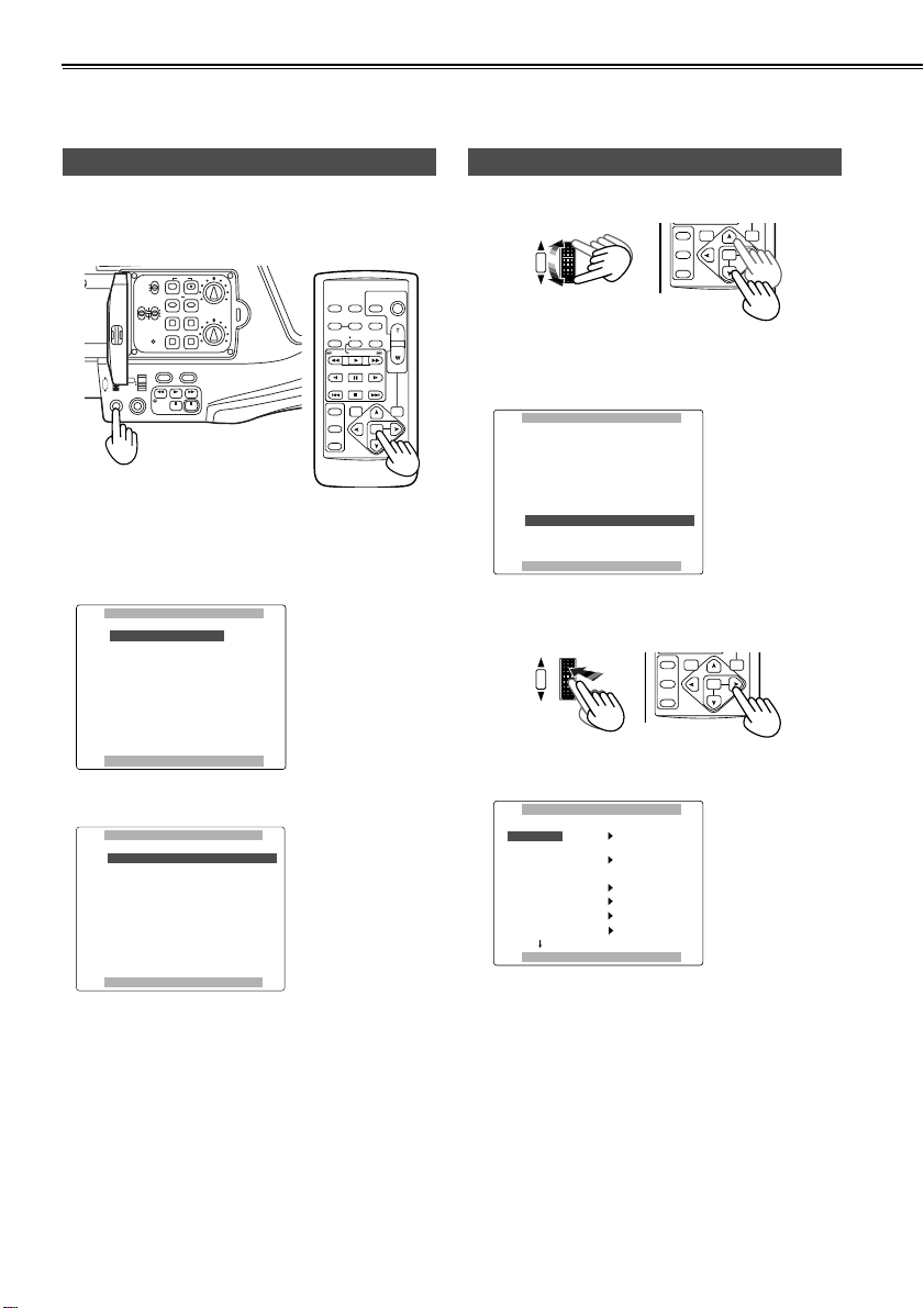
1 Press the MENU button.
• When the remote
control unit is used
REC
ZOOM SPEED
H
OFF/M
L
RESETCOUNTER
AUDIO IN
SHUTTER/IRIS
PUSH
VOL/JOG
MENU
AUTO
MANUAL
WHITE BAL
FRONT
REAR
CH1 CH2
RESET
MIC
LINE
MIC
FOCUS USER 2
SEARCH
USER 3
CH1
AUDIO LEVEL
MODE CHKSNS
CH2
OISZEBRA
SEARCHD.ZOOM
STILL
The main items now appear on the screen.
• The camera menu appears in the CAMERA mode;
the VCR menu appears in the VCR mode.
[CAMERA mode]
`^jbo^==jbkr
N=K=p`bkb==cfib
O=K=`^jbo==pbqrm
P=K=pt==jlab
Q=K=ob`loafkd==pbqrm
R=K=afpmi^v==pbqrm
S=K=lqebo==crk`qflkp
OSD
COUNTER
MULTI/
P-IN-P
STILL ADV
INDEX
SELECT
STORE
OFF/ON
P.B.DIGITAL
DATE/
TIME
RESET TITLE
REC A.DUB
PLAY/REW FF/
PAUSE
STOP INDEX
VAR.
SEARCH
PHOTO
STILL ADV
START/
STOP
SHOT
ZOOM
VOL +
-
PB.
ZOOM
MENU
SET
ITEM
Selecting the main items
2 Turn the multi dial.
SELECT
VAR.
SHUTTER/IRIS
PUSH
VOL/JOG
STORE
OFF/ON
P.B.DIGITAL
SEARCH
PB.
ZOOM
MENU
SET
ITEM
The highlighting moves to the next main item in
turn.
Example:
`^jbo^==jbkr
N=K=p`bkb==cfib
O=K=`^jbo==pbqrm
P=K=pt==jlab
Q=K=ob`loafkd==pbqrm
R=K=afpmi^v==pbqrm
S=K=lqebo==crk`qflkp
mrpe==jbkr==ql==bufq
3 Press the multi dial at the position of the item to be
displayed.
HUTTER/IRIS
PUSH
VOL/JOG
SELECT
STORE
OFF/ON
P.B.DIGITAL
SEARCH
VAR.
PB.
ZOOM
MENU
SET
ITEM
mrpe==jbkr==ql==bufq
The sub items are now displayed.
Example:
[VCR mode]
s`o==crk`qflkp
N=K=mi^v_^`h==crk`qflkp
O=K=pt==jlab
P=K=ob`loafkd==pbqrm
Q=K=^s==fkLlrq==pbqrm
R=K=afpmi^v==pbqrm
S=K=lqebo==crk`qflkp
mrpe==jbkr==ql==bufq
lqebo==crk`qflkp
objlqb
as==`lkqoli
as==`ja==pbi
ob`==i^jm
_bbm==plrka
`il`h==pbq
s`oN s`oO
lcc
lcc
ob`==m
lcc
lcc
||||
mrpe==jbkr==ql==obqrok
62
Page 3
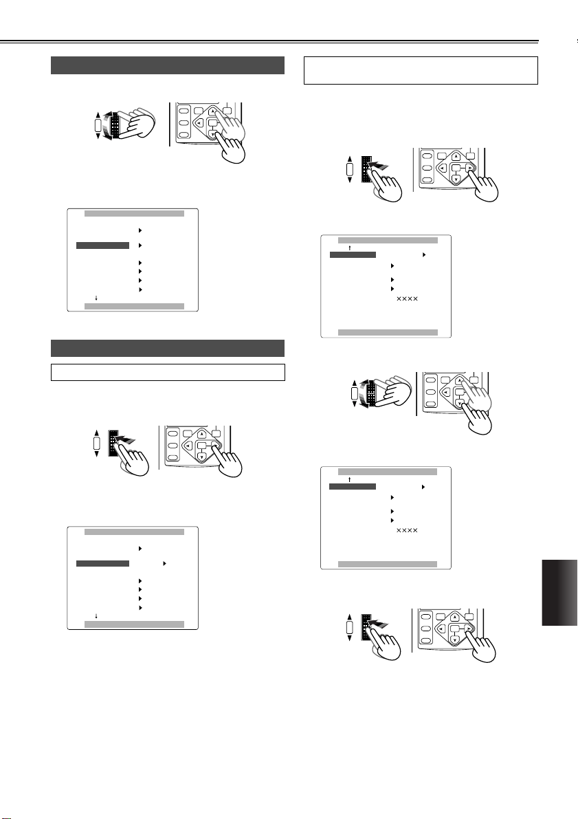
Selecting the sub items
S
S
S
S
S
4 Turn the multi dial.
HUTTER/IRIS
PUSH
VOL/JOG
The highlighting moves to the next sub item in turn.
Example:
lqebo==crk`qflkp
objlqb
as==`lkqoli
as==`ja==pbi
ob`==i^jm
_bbm==plrka
`il`h==pbq
mrpe==jbkr==ql==obqrok
Entering the settings
For items whose setting is to be selected
SELECT
STORE
OFF/ON
P.B.DIGITAL
s`oN
lcc
buq
_lqe==`e^fk
ob`==m
lcc
lcc
||||
SEARCH
VAR.
PB.
ZOOM
MENU
SET
ITEM
5 Press the multi dial at the position of the item to be
changed, and move q to the desired setting.
HUTTER/IRIS
PUSH
VOL/JOG
The setting is now changed.
Example:
lqebo==crk`qflkp
objlqb
as==`lkqoli
as==`ja==pbi
ob`==i^jm
_bbm==plrka
`il`h==pbq
mrpe==jbkr==ql==obqrok
SELECT
STORE
OFF/ON
P.B.DIGITAL
s`oN
lcc
buq
_lqe==`e^fk
ob`==m
lcc
lcc
||||
SEARCH
VAR.
PB.
ZOOM
MENU
SET
ITEM
For items whose numerical value setting is to be
changed
5 Press the multi dial at the position of the item to be
changed, then press the dial again and move q to
the position of the numerical value which is to be
changed.
HUTTER/IRIS
PUSH
VOL/JOG
Example:
lqebo==crk`qflkp
qfjb==pefcq
q^mb==molqb`q
fo==iba
rpbo==cfib
elro==jbqbo
mrpe==jbkr==ql==obqrok
• Turn the multi dial, and change the setting.
HUTTER/IRIS
PUSH
VOL/JOG
Example:
lqebo==crk`qflkp
qfjb==pefcq
q^mb==molqb`q
fo==iba
rpbo==cfib
elro==jbqbo
mrpe==jbkr==ql==obqrok
• Press the multi dial to enter the setting.
HUTTER/IRIS
PUSH
VOL/JOG
SELECT
STORE
OFF/ON
P.B.DIGITAL
||||
mltbo==lcc
^rql
||||
e
SELECT
STORE
OFF/ON
P.B.DIGITAL
||||
mltbo==lcc
^rql
||||
e
SELECT
STORE
OFF/ON
P.B.DIGITAL
lcc
H=OÜ
SEARCH
SEARCH
VAR.
VAR.
PB.
ZOOM
MENU
SET
ITEM
VAR.
PB.
SEARCH
ZOOM
MENU
SET
ITEM
PB.
ZOOM
MENU
SET
ITEM
MENUS
63
Page 4
Menu operations (cont.)
M
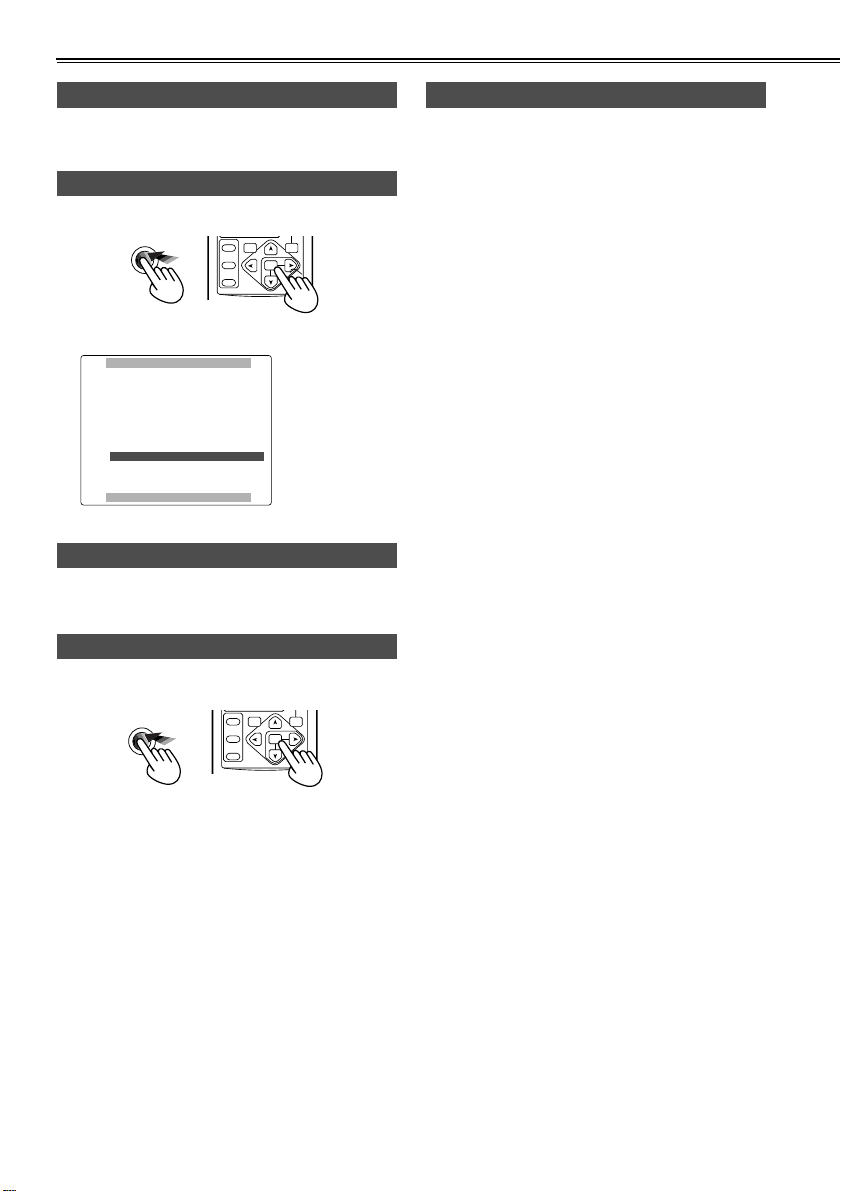
Setting other sub items
6 To set another sub item, repeat steps 4 and 5.
Returning to the main item screen
7 Press the MENU button.
ENU
Example:
`^jbo^==jbkr
N=K=p`bkb==cfib
O=K=`^jbo==pbqrm
P=K=pt==jlab
Q=K=ob`loafkd==pbqrm
R=K=afpmi^v==pbqrm
S=K=lqebo==crk`qflkp
mrpe==jbkr==ql==bufq
Setting other main items
SELECT
STORE
OFF/ON
P.B.DIGITAL
SEARCH
VAR.
PB.
ZOOM
MENU
SET
ITEM
8 To set another main item, repeat steps 2 to 5.
Releasing the menu mode
Initializing the menu settings
• When “INITIAL” is selected as the USER FILE item
setting on the OTHER FUNCTIONS screen, you can
return the menu settings in the currently used user
file to their factory settings. (P73)
• If “INITIAL” is selected as the SAVE/INT item setting
on the SCENE FILE screen while you are using a
scene file (in the SETTING item on the SCENE FILE
screen), you can return the menu settings in that
scene file to their factory settings. (P66)
9 Press the MENU button again.
MENU
64
SELECT
STORE
OFF/ON
P.B.DIGITAL
SEARCH
VAR.
PB.
ZOOM
MENU
SET
ITEM
Page 5

Menu configuration
CAMERA mode menu
CAMERA MENU
SCENE FILE
(P66)
CAMERA SETUP
(P66)
SW MODE
(P68)
RECORDING SETUP
(P69)
DISPLAY SETUP
(P71)
OTHER FUNCTIONS
(P72)
SYNCRO SCAN
ASPECT CONV
COLOR BAR
SETUP
REC SPEED
AUDIO REC
WIND CUT
ID SET
TIME STAMP
TCG
FIRST REC TC
TC PRESET
UB MODE
UB PRESET
EFFECT
ONE-SHOT REC
REC TIME
REMOTE
DV CONTROL
DV CMD SEL
REC LAMP
BEEP SOUND
CLOCK SET
TIME SHIFT
TAPE PROTECT
IR LED
USER FILE
HOUR METER
SCENE FILE
SETTING
NAME EDIT
SAVE/INIT
USER1
USER2
USER3
FOCUS RING
IRIS DIAL
ZOOM MODE
HANDLE ZOOM
HANDLE S/S INHIBIT
SNS
SNS SET MEM
D. ZOOM
ZEBRA DETECT
VIDEO OUT OSD
DATE/TIME
LEVEL METER
DISPLAY
LCD BACKLIGHT
LCD/EVF SET
SELF SHOOT
EVF MODE
EVF COLOR
EVF DETAIL
DETAIL LEVEL
CHROMA LEVEL
CHROMA PHASE
COLOR TEMP
MASTER PED
AE SHIFT
SKIN TONE DTL
REC MODE
VCR mode menu
VCR FUNCTIONS
PLAYBACK FUNCTIONS
(P67)
SW MODE
(P68)
RECORDING SETUP REC SPEED
(P69)
AV IN/OUT SETUP
(P71)
DISPLAY SETUP
(P71)
OTHER FUNCTIONS
(P72)
SEARCH
32K (12bit) AUDIO
AUDIO OUT
USER1
USER2
A. DUB INPUT
DV OUT
VIDEO OUT OSD
DATE/TIME
LEVEL METER
DISPLAY
CAMERA DATA
LCD BACKLIGHT
LCD/EVF SET
EVF MODE
EVF COLOR
AUDIO REC
WIND CUT
1394 TC REGEN
TCG
FIRST REC TC
TC PRESET
1394 UB REGEN
UB MODE
UB PRESET
REMOTE
CLOCK SET
TIME SHIFT
USER FILE
HOUR METER
MENUS
65
Page 6

Menu configuration (cont.)
SCENE FILE screen
Item/
(Display
mode)
SCENE FILE
(CAM)
SETTING
(CAM)
Description of settings
Settings corresponding to four shooting conditions are saved as scene files in this camera-recorder. Use this item to select the
scene file to be used.
1. SCENE1:
For files where the various menu settings
are normal.
2. SCENE2:
The same as SCENE 1 (this is an extra).
3. B.PRESS:
This file is useful for shooting dark areas
with a sharper contrast.
4. MOVIE-LIKE:
This file is useful for shooting movie-like
images.
<Note>
You can change the settings in the scene files
using the SETTING item.
Use this to change the settings in the scene
files.
DETAIL LEVEL:
–7 --- 0 --- +7
Set this level in the “–” direction to soften
the image outlines.
When it is set in the “+” direction, the
image outlines are emphasized and sharp
images are produced, but the amount of
noise is increased slightly.
CHROMA LEVEL:
–7 --- 0 --- +7
Set this level in the “–” direction to make
the image colors lighter.
Set it in the “+” direction to make them
darker.
CHROMA PHASE:
–7 --- 0 --- +7
Use this to adjust the hue.
COLOR TEMP:
–7 --- 0 --- +7
Set this in the “–” direction to make the
images more reddish overall.
Set it in the “+” direction to make the
images more bluish overall.
MASTER PED:
–15 --- 0 --- +15
Set this in the “–” direction to make the
images darker overall. When a setting
below –5 is selected, the dark parts of the
images may become blackened out.
When it is set in the “+” direction, the dark
parts of the images (such as the shadows)
become brighter.
AE SHIFT:
–4 --- 0 --- +4
Use this to adjust the auto iris setting.
Set it in the “–” direction for a darker setting.
Set it the “+” direction for a brighter setting.
Item/
(Display
mode)
NAME EDIT
(CAM)
SAVE/INIT
(CAM)
Description of settings
SKIN TONE DTL:
OFF, ON
When ON is selected, soft skin tones are
reproduced when people are shot, making
them look more attractive.
REC MODE:
NORM
Shooting is performed using field recording (60 fields per second).
FRAME
Shooting is performed using frame recording (30 frames per second).
High-quality images can be obtained at
this setting when playing back still images,
for example.
Use this to edit the name of the selected
scene file.
SAVE:
The changed settings in the scene file
(one of the files listed in the file selection
item) are saved.
The original scene file settings will be
restored when the menu mode is
released, the operation is switched to the
VCR mode or when the power is turned off
if SAVE has not been selected.
INITIAL:
The selected scene file settings are
returned to the factory settings.
The underlining indicates the factory setting.
CAMERA SETUP screen
Item/
(Display
mode)
SYNCRO
SCAN
(CAM)
ASPECT
CONV
(CAM)
COLOR BAR
(CAM)
SETUP
(CAM)
Description of settings
Use this to adjust the synchro scan shutter
speed used for shooting images on a TV
screen, etc. (P38, 39)
1/60.3 --- 1/250
Use this to select the aspect ratio of the
images which are to be recorded. (P35)
Cannot be changed during still shooting.
, LETTER BOX, SQUEEZE
NORMAL
Select ON to show the color bar.
Cannot be changed during still shooting.
OFF, ON
Use this to add the setup level (black level).
0%:
The setup level is not added.
7.5%:
A 7.5% setup level is added for recording.
66
The underlining indicates the factory setting.
Page 7

PLAYBACK FUNCTIONS screen
Item/
(Display
mode)
SEARCH
(VCR)
32K (12bi t)
AUDIO
(VCR)
Description of settings
Use this to set the operation to be performed
when an INDEX button (i or u) on the
remote control unit is pressed.
PHOTO:
A photo search is conducted. (P47)
SCENE:
An index search is conducted. (P47)
Use this to set the sound to be output as CH1
and CH2 signals when playing back a tape
that was recorded in the 32K (12-bit) audio
mode.
ST1:
This selects the sound that was recorded
during shooting.
CH1 signals = CH1 track
CH2 signals = CH2 track
ST2:
This selects the sound that was dubbed
on the recording.
CH1 signals = CH3 track
CH2 signals = CH4 track
MIX:
This mixes the sound that was recorded
during shooting and the sound that was
dubbed on the recording.
CH1 signals = CH1 + CH3 tracks
CH2 signals = CH2 + CH4 tracks
<Note>
When sound is recorded in the 48K (16-bit)
audio mode, CH3 and CH4 do not exist so
the following always stands:
CH1 signals = CH1 track
CH2 signals = CH2 track
Item/
(Display
mode)
AUDIO OUT
(VCR)
The underlining indicates the factory setting.
Description of settings
Use this to set the audio signals to be output
from the AV IN/OUT jack when the tape is
played back.
CH1•CH2:
CH1 output = CH1 signals
CH2 output = CH2 signals
CH1:
CH1 output = CH1 signals
CH2 output = CH1 signals
CH2:
CH1 output = CH2 signals
CH2 output = CH2 signals
32K (12bit) AUDIO item/AUDIO OUT item settings and audio track signals output from the
AUDIO IN/OUT jack
Audio recording
mode
32K (12-bit)
48K (16-bit)
32K (12bit) AUDIO
item setting
ST1
ST2
MIX –––– CH1+CH3 CH2+CH4
––––
AUDIO OUT
item setting
CH1•CH2
CH1
CH2
CH1•CH2
CH1
CH2
CH1•CH2
CH1
CH2
AUDIO IN/OUT jack
CH1 output
CH1
CH1
CH2
CH3
CH3
CH4
CH1
CH1
CH2
AUDIO IN/OUT jack
CH2 output
CH2
CH1
CH2
CH4
CH3
CH4
CH2
CH1
CH2
MENUS
67
Page 8

Menu configuration (cont.)
SW MODE screen
Item/
(Display
mode)
USER1
(CAM) (VCR)
The underlining indicates the factory setting.
Description of settings
This enables one function to be allocated to
the USER1 button.
g Camera menu mode
(PUSH) AF+ZOOM:
Select this to execute one-touch zooming.
(P36)
(PUSH) AF:
Select this to switch to auto focus mode
when the camera-recorder is operated in
the manual focus mode but only while the
button is held down.
WHITE BAL:
This works in the same way as the WHITE
BAL button when the white balance is to
be set. (P40, 41)
AWB LOCK:
Select this to enable operations to be performed with the white balance that was in
effect when the button was pressed while
operating the camera-recorder in the auto
white balance mode. (P40)
BACKLIGHT:
Select this to set the backlight compensation function to ON or OFF. (P36)
SPOTLIGHT:
Select this to set the auto iris control for
the spotlight to ON or OFF.
REC CHECK:
Select this to perform a rec check. (P12)
D. ZOOM:
Select this to perform digital zooming.
(P31)
WHITEFADE:
Select this to fade out the whole image in
white while the button is held down during
shooting. At the same time, the sound is
also faded out.
Conversely, fade-in in white occurs when
the button is released. At the same time,
the sound is also faded in.
BLACKFADE:
Select this to fade out the whole image in
black when the button is held down during
shooting. At the same time, the sound is
also faded out.
Conversely, fade-in in black occurs when
the button is released. At the same time,
the sound is also faded in.
PHOTO SHOT:
Select this for photo shot recording. (P33)
INDEX:
Select this for index recording. (P36)
SNS:
Select this to set the camera-recorder to
the high-sensitivity shooting mode. (P32)
Item/
(Display
mode)
USER2
(CAM) (VCR)
USER3
(CAM) (VCR)
Description of settings
EVF DTL:
Select this to emphasize the outlines of
the images on the screen when the button
is pressed so that the subject becomes
easier to bring into focus. “EVF DTL ON”
appears for about 2 seconds in the center
of the screen after the button has been
pressed. However, the regular images are
what is recorded, not the ones with their
outlines emphasized.
The original images are restored by pressing the button ag ain. “EVF DTL OF F”
appears for about 2 seconds in the center
of the screen.
LUMI-FLICK:
Select this to make the screen flicker so
that images which will give the impression
that reels of photographic film are turning
just as they did years ago are recorded.
AE LOCK:
Select this to set the camera-recorder to
the AE lock mode. (P36)
STILL:
To shoot still pictures. (P36)
COLOR BAR:
To show the color bar.
EFFECT:
To select image effects.
g VCR menu mode
BLANK SEARCH:
Select this to conduct a blank search.
(P46)
AUDIO DUB:
This works in the same way as the A.DUB
button on the remote control unit when
performing audio dubbing. (P52)
INDEX:
Select this for index recording. (P36)
This enables one function to be allocated to
the USER2 button.
For further details, refer to the USER1 item.
g Camera menu mode
(PUSH) AF+ZOOM, (PUSH) AF, WHITE
BAL, AWB LOCK, BACKLIGHT, SPOTLIGHT, REC CHECK, D. ZOOM, WHITEFADE, BLACKFADE, PHOTO SHOT,
INDEX, SNS, EVF DTL, LUMI-FLICK, AE
LOCK, STILL, COLOR BAR, EFFECT
g VCR menu mode
BLANK SEARCH, AUDIO DUB, INDEX
This enables one function to be allocated to
the USER3 button.
For further details, refer to the USER1 item.
g Camera menu mode
(PUSH) AF+ZOOM, (PUSH) AF, WHITE
BAL, AWB LOCK, BACKLIGHT, SPOTLIGHT, REC CHECK, D. ZOOM, WHITEFADE, BLACKFADE, PHOTO SHOT,
INDEX, SNS, EVF DTL, LUMI-FLICK,
AE LOCK, STILL, COLOR BAR, EFFECT
68
Page 9

SW MODE screen
Item/
(Display
mode)
FOCUS
RING
(CAM)
IRIS DIAL
(CAM)
ZOOM
MODE
(CAM)
HANDLE
ZOOM (CAM)
HANDLE S/S
INHIBIT
(CAM)
SNS (CAM) Use this to select the high-sensitivity shooting
SNS SET MEM
(CAM)
D. ZOOM
(CAM)
Description of settings
Use this to select the function to be allocated
to the focus ring.
ZOOM:
Zooming can be perf ormed us ing the
focus ring when the camera-recorder is
operated in the auto focus mode.
IRIS:
Iris adjustments can be performed using
the focus ring when the camera-recorder
is operated in the auto focus mode and
the iris is to be adjusted manually.
OFF:
The focus ring is used to perform manual
focus adjustments only.
Use this to set how the iris is to be controlled
by the direction in which the multi dial is
rotated when the iris is to be adjusted manually.
DOWN OPEN:
The iris opens when the multi dial is
turned downward.
UP OPEN:
The iris opens when the multi dial is
turned upward.
Use this to set the speed of the motordriven
lens zoom. (P31)
NORM : Standard
HIGH : High speed
LOW : Low speed
To select the HANDLE ZOOM switch. (P31)
L/OFF/H, L/M/H
Use this to set whether the recording operation is to be performed using the START/
STOP button on the lens.
OFF:
Recording is permitted.
ON:
Recording is inhibited so as to prevent
operation from being conducted by mistake.
mode. (P32)
IR, SUPER_IR, COLOR_NS
To select whether to record the SNS mode.
OFF:
The mode is not recorded.
ON:
The mode is recorded.
Use this to select the magnification level for
the digital zoom. (P31)
, x160
x24
RECORDING SETUP screen
Item/
(Display
mode)
REC SPEED
(CAM) (VCR)
AUDIO REC
(CAM) (VCR)
WIND CUT
(CAM) (VCR)
ID SET
(CAM)
TIME STAMP
(CAM)
1394 TC
REGEN
(VCR)
The underlining indicates the factory setting.
Description of settings
Use this to select the recording duration
mode.
SP : SP (standard recording) mode.
LP : LP (long recording) mode.
Use this to select the digital audio recording
system.
32K (12bit):
The sound is recorded using the 12-bit/32
kHz (4 channels) recording system.
Select this mode when leaving the sound
heard during shooting intact even when
audio dubbing is performed on an existing
recording.
48K (16bit):
The sound is recorded using the 16-bit/48
kHz (2 channels with a good sound quality) recording system.
The sound heard during shooting will be
erased when dubbing over an existing
recoding.
Select ON to reduce the noise generated by
the wind bl owing in to the microphon e in
windy conditions. Effective with FRONT and
REAR (LINE/MIC) input.
OFF, ON
Use this to set the ID (5 characters) information. The ID information set is displayed when
the color bar mode is established.
• Characters which can be set:
(space), A to Z, 0 to 9, ., /, :
Set this to REC to record the date and time
that were selected using the DATE/TIME setting item (P71) on the DISPLAY SETUP
screen as an image on the tape.
NO-REC, REC
Use this to select the time code to be
recorded when recording the signals of the
unit connected to the DV connector.
OFF:
The time code that was selected using the
TCG setting item and FIRST REC TC setting item is used for the recording.
ON:
The time code of the signals which are
input to the DV connector are used for the
recording.
• When ON has been selected for this item,
the time code of the signals concerned
takes precedence over the TCG item and
FIRST REC TC item settings.
• If no signals are input to the DV connector,
the TCG item and FIRST REC TC item
settings are used.
MENUS
69
Page 10

Menu configuration (cont.)
RECORDING SETUP screen
Item/
(Display
mode)
TCG
(CAM) (VCR)
FIRST
REC TC
(CAM) (VCR)
TC PRESET
(CAM) (VCR)
1394 UB
REGEN
(VCR)
Description of settings
Use this to set the mode in which to advance
the time code.
FREE RUN:
The time code is advanced continuously
regardless of the operation mode.
It is recorded on the basis of the time
appearing on the camera-recorder’s calendar clock.
REC RUN:
The time code is advanced only when
recording is underway.
It is recorded while ensuring that continuity is maintained with the time code
already recorded on the tape when shooting with frame-to-frame continuity.
Use this to select the time code to be
recorded when recording is started.
REGEN:
Select this to record the time code that will
ensure continuity with the time code
already on the tape.
The time code is recorded in the REC
RUN mode regardless of the setting
selected for the TCG item.
PRESET:
Select this to record the time code using
the value selected by the TC PRESET
item as the initial value.
However, when shooting with frame-toframe continuity has taken place, the time
code is recorded to ensure continuity with
the time code already on the tape.
Use this to set the initial value of the time
code to be recorded.
The item takes effect when “PRESET” has
been selected as the FIRST REC TC item
setting.
Use this to select the user’s bit to be recorded
when recording the signals of the unit connected to the DV connector.
OFF:
The user’s bit selected by the UB MODE
item is recorded.
ON:
The user’s bit of the signals input to the
DV connector is recorded.
• When “ON” has been selected as this
item’s setting, it takes precedence over
the UB MODE item setting.
• If the signals do not contain the user’s bit
information, the user’s bit is not recorded.
• If no signals are input to the DV connector,
the UB MODE item setting is used for the
recording.
Item/
(Display
mode)
UB MODE
(CAM) (VCR)
UB PRESET
(CAM) (VCR)
EFFECT
(CAM)
ONE-SHOT
REC
(CAM)
REC TIME
(CAM)
Description of settings
Use this to set what is to be recorded as the
user’s bit.
USER:
The user’s information is recorded.
TIME:
The recording time is recorded.
DATE:
The recording date is recorded.
TCG:
The time code is recorded.
Use this to set the user’s bit.
For this, however, “USER” must have been
selected as the UB MODE item setting.
Adds effects to the images.
OFF, WIPE, MIX
Use the ON setting when shooting on a
frame-by-frame basis.
OFF:
Frame-by-frame shooting is not performed.
ON:
The camera-recorder is set to the
frameby-frame shooting mode.
When the START/STOP button is
pressed, recording proceeds for the number of seconds selected by the REC TIME
item setting, and then the camerarecorder is set to the REC PAUSE mode.
Use this to set the recording time for framebyframe shooting.
0.5s : 0.5 sec. 1s : 1.0 sec.
1.5s : 1.5 sec. 2s : 2.0 sec.
70
The underlining indicates the factory setting.
Page 11

AV IN/OUT SETUP screen
Item/
(Display
mode)
A. DUB
INPUT
(VCR)
DV OUT
(VCR)
Description of settings
Use this to select the sound to be recorded
when performing audio dubbing.
MIC:
The sound of the internal microphone or
external microphone is recorded. (P52)
A_IN:
The sound of the audio unit connected to
the AUDIO IN/OUT jack is recorded.
<Note>
If audio dubbing is performed on a recording
which was made in the 48K (16-bit) audio
mode, the sound heard during shooting will
be overwritten and the dubbed sound
recorded in its place.
Select the ON setting when converting analog
input signals into digital signals and outputting them from the DV connector.
OFF, ON
DISPLAY SETUP screen
Item/
(Display
mode)
ZEBRA
DETECT
(CAM)
VIDEO OUT
OSD
(CAM) (VCR)
DATE/TIME
(CAM) (VCR)
LEVEL
METER
(CAM) (VCR)
DISPLAY
(CAM) (VCR)
CAMERA
DATA
(VCR)
LCD
BACKLIGHT
(CAM) (VCR)
The underlining indicates the factory setting.
Description of settings
Use this to set the brightness level at which
the zebra patterns are to be displayed.
80%, 85%, 90%, 95%, 100%, 105%
Select the ON setting to output the information displayed on the screen together with the
signals from the VIDEO IN/OUT jack.
OFF, ON
Use this to set whether to display the date
and/or time on the screen and on the signals
that are output from the VIDEO IN/OUT jack.
OFF:
The date and time are not displayed.
TIME:
The time is displayed.
DATE:
The date is displayed.
TIME&DATE:
The date and time are displayed.
• If any setting other than OFF is selected,
the time and/or date are displayed for the
signals that are output from the AV IN/
OUT jack, regardless of the setting
selected for the VIDEO OUT OSD item.
Select ON to display the audio level meter on
the screen.
OFF, ON
Use this to set the amount of information to
be displayed on the screen. (P61)
OFF, PARTIAL, ALL
With the ON setting, the camera settings
(vibration reduction, F-number, gain value
and white balance information) at the time of
shooting are displayed when the tape is
played back.
OFF, ON
<Note>
When a tape on which the unit’s camera settings has been recorded is played back on
another unit, the camera settings may not be
displayed properly.
Use this to adjust the backlight of the LCD
monitor.
When HI is selected, the backlight is made
brighter than usual.
HI, NORMAL
MENUS
71
Page 12

Menu configuration (cont.)
DISPLAY SETUP screen
Item/
(Display
mode)
LCD/EVF
SET
(CAM) (VCR)
SELF SHOOT
(CAM)
EVF MODE
(CAM) (VCR)
EVF COLOR
(CAM) (VCR)
EVF DETAIL
(CAM) (VCR)
Description of settings
Use this to adjust the display level of the
images appearing in the viewfinder or on the
LCD monitor.
LCD BRIGHTNESS:
Select this to adjust the brightness of the
images on the LCD monitor.
LCD COLOR LEVEL:
Select this to adjust the color level of the
images on the LCD monitor.
EVF BRIGHTNESS:
Select this to adjust the brightness of the
images in the viewfinder.
When MIRROR is selected, an image with
the left and right sides reversed will appear
on the LCD monitor when shooting a selfportrait.
NORMAL, MIRROR
Use this to select to switch the screen
images.
ON:
The images are always displayed in the
viewfinder.
AUTO:
The images in the viewfinder are cleared
when the LCD monitor is opened.
Select ON to display the images on the viewfinder screen in color.
OFF:
The images are displayed in black and
white.
ON:
The images are displayed in color.
When ON is selected, the contours of the
images in the viewfinder and on the LCD
monitor are emphasized to make focusing
easier.
However, the images recorded will be normal
images without emphasized contours.
OFF, ON
OTHER FUNCTIONS screen
Item/
(Display
mode)
REMOTE
(CAM) (VCR)
DV
CONTROL
(CAM)
DV
CMD SEL
(CAM)
REC LAMP
(CAM)
Description of settings
Use this to set the operations to be performed
using the accessory remote control unit.
(P19)
VCR1:
Operations performed using the remote
control unit which has been set up for use
with VCR1 are accepted.
VCR2:
Operations performed using the remote
control unit which has been set up for use
with VCR2 are accepted.
OFF:
No operations performed using a remote
control unit are accepted.
Use this to set the control method to be used
when a backup unit is connected to the DV
connector and backup recording is to be performed.
OFF:
The backup unit is not controlled.
EXT:
The backup unit is controlled using the
camera-recorder’s START/STOP button.
The images shot using the camerarecorder are recorded using the backup
unit. (The camera-recorder does not perform the recording operation.)
BOTH:
The images shot using the camerarecorder are recorded by both the camerarecorder and the backup unit.
CHAIN:
When the camera-recorder’s tape
approaches its end during shooting,
recording is automatically started by the
backup unit that has been waiting in the
recording standby mode.
Use this to set the recording operation to be
performed by the backup unit when the camera-recorder’s START/STOP button is
pressed.
REC_P:
The START/STOP button switches
between recording and rec pause.
STOP:
The START/STOP button switches
between recording and stop.
<Note>
If the backup unit does not have a rec pause
function, select STOP.
Select ON to light the tally lamp during shooting. (P77)
, ON
OFF
72
The underlining indicates the factory setting.
Page 13

OTHER FUNCTIONS screen
Item/
(Display
mode)
BEEP
SOUND
(CAM)
CLOCK SET
(CAM) (VCR)
TIME SHIFT
(CAM) (VCR)
TAP E
PROTECT
(CAM)
IR LED
(CAM)
Description of settings
Select ON to be warned by a beep that the
shooting has started or ended or that a problem has occurred.
OFF, ON
The beeps are output as audio signals from
the PHONES jack and AV IN/OUT jack. When
a beep is sounded, the audio signals from the
built-in microphone are muted and the beep
is output instead.
One beep sounds:
• when the POWER lever is set to the ON
position
• when shooting has started
Two beeps sound:
• when shooting is paused
10 beeps sound in succession:
• when a cassette tape has not been inserted
• when the cassette tape is set to the record-
ing inhibited status
• when condensation has formed inside the
camera-recorder
• when a problem has occurred in the camera-recorder
Use this to set the camera-recorder’s internal
calendar.
The time set using this item is added to the
clock time of the internal calendar (time difference compensation) and displayed on the
viewfinder and LCD monitor. The added time
is also recorded on the tape.
+23h --- +1h, OFF, –1h --- –23h
(In 1-hour increments)
When the camera-recorder has been left in
the pause mode for about 5 minutes, it is
automatically set to the tape protection mode.
Use this item to select the kind of tape protection mode to be established.
POWER OFF:
The camer a-record er’s power is set to
OFF.
STBY:
The cylinder head is set to the stop status.
Use this to set the control over the infrared
light which is used during high-sensitivity
recording. (P32)
AUTO:
The infrared light comes on as soon as the
high-sensitivity shooting mode is established.
OFF:
The infrared light does not come on no
matter whether the high-sensitivity shooting mode is established or not.
Item/
(Display
mode)
USER FILE
(CAM) (VCR)
HOUR
METER
(CAM) (VCR)
The underlining indicates the factory setting.
Description of settings
LOAD:
The menu (except scene file) settings
which were saved last are loaded.
SAVE:
The changed menu settings are saved.
INITIAL:
The menu settings are returned to the factory settings.
• When the power is turned off without
selecting SAVE, the VCR mode menu settings will be saved but the CAMERA mode
menu settings will be returned to the original settings.
• When a LOAD or INITIAL operation has
been performed, set the camerarecorder’s POWER lever first to the OFF
position and then back to ON in order to
ensure that the settings concerned will
take effect.
Use this to display the total running time (a 5digit figure in 1-hour increments) of the cylinder head.
MENUS
73
 Loading...