

Page 1
Before attempting to connect, operate or adjust this product, please read these instructions completely.
AG- P
F0301T2051
@
Printed in Japan
VQT9277-2
P
Digital Video Camera Recorder
NTSC
Page 2
2
This camera recorder is designed to be used exclusively with the standard size of DV tapes. Do not use DVCPRO tapes or other
sizes of tapes.
indicates safety information.
CAUTION
RISK OF ELECTRIC SHOCK
DO NOT OPEN
CAUTION: TO REDUCE THE RISK OF ELECTRIC SHOCK,
DO NOT REMOVE COVER (OR BACK).
NO USER SERVICEABLE PARTS INSIDE.
REFER TO SERVICING TO QUALIFIED SERVICE PERSONNEL.
The lightning flash with arrowhead symbol,
within an equilateral triangle, is intended to
alert the user to the presence of uninsulated
“dangerous voltage” within the product’s
enclosure that may be of sufficient magnitude
to constitute a risk of electric shock to
persons.
The exclamation point within an equilateral
triangle is intended to alert the user to the
presence of important operating and
maintenance (service) instructions in the
literature accompanying the appliance.
WARNING:
TO REDUCE THE RISK OF FIRE OR SHOCK
HAZARD, DO NOT EXPOSE THIS
EQUIPMENT TO RAIN OR MOISTURE.
CAUTION:
TO REDUCE THE RISK OF FIRE OR SHOCK
HAZARD AND ANNOYING INTERFERENCE,
USE THE RECOMMENDED ACCESSORIES
ONLY.
CAUTION:
TO REDUCE THE RISK OF FIRE OR SHOCK
HAZARD, REFER CHANGE OF SWITCH
SETTING INSIDE THE UNIT TO QUALIFIED
SERVICE PERSONNEL.
FCC Note:
This device complies with Part 15 of the FCC Rules.
To assure continued compliance follow the attached
installation instructions and do not make any
unauthorized modifications.
This equipment has been tested and found to comply
with the limits for a class A digital device, pursuant to
Part 15 of the FCC Rules. These limits are designed
to provide reasonable protection against harmful
interference when the equipment is operated in a
commercial environment. This equipment generates,
uses, and can radiate radio frequency energy and, if
not installed and used in accordance with the
instruction manual, may cause harmful interference to
radio communications. Operation of this equipment in
a residential area is likely to cause harmful
interference in which case the user will be required to
correct the interference at his own expense.
Replace battery with part No. CR2032 only.
Use of another battery may present a risk of fire or
explosion.
Caution—Battery may explode if mistreated.
Do not recharge, disassemble or dispose of in fire.
ATTENTION:
The product you have purchased is powered by a
nickel cadmium battery which is recyclable. At the
end of it’s useful life, under various state and local
laws, it is illegal to dispose of this battery into your
municipal waste stream.
Please call 1-800-8-BATTERY for information on how
to recycle this battery.
Ni-Cd
RBRC
RBRC
Page 3

3
Contents
Introduction.......................................................4
Features.............................................................4
Features of the camera unit....................................4
Features of the VTR unit.........................................4
System configuration.......................................5
Parts and their functions..................................6
Preparation......................................................10
Using the AU-BP402 or AJ-BP490
battery pack made by Panasonic..........................10
Using a battery pack made by Anton Bauer..........11
Using the NP-1B battery pack made by Sony.......11
Using an AC power supply
(with the AJ-B75 AC adapter) ...............................12
Attaching the lens..................................................12
Mounting the unit on a tripod.................................13
Detaching the unit from the tripod attachment......13
Attaching the viewfinder and microphone.............13
Attaching the shoulder belt (optional accessory) ..13
Setting the camera ID ...........................................14
Setting the date and time......................................14
Lens adjustments and checks.......................15
Flange back adjustment........................................15
White shading check.............................................15
White shading adjustment.....................................15
Viewfinder displays ........................................16
Viewfinder lamp displays.......................................16
Viewfinder screen status displays.........................16
Selecting the viewfinder screen display................19
White balance and black balance adjustment
....20
Automatic white balance adjustment.....................20
Automatic black balance adjustment.....................20
Electronic shutter settings.............................21
Shutter modes.......................................................21
Setting the shutter mode and speed.....................21
Setting the synchro scanning mode......................21
Time data settings ..........................................22
Setting the user’s bit..............................................22
Setting the time code ............................................22
Scene files.......................................................23
Scene file function.................................................23
Scene file setting method......................................23
Editing scene filenames (Example: USER files) ...23
Returning a scene filename to its default..............24
How to use file select............................................24
List of scene file settings.......................................25
List of file settings..................................................25
Normal recording............................................26
Recording methods...............................................26
Scene-to-scene continuity.....................................26
Audio recording..............................................27
Selecting the audio input signals...........................27
Adjusting the audio recording level.......................27
Monitoring the sound during recording..................27
Playback (checking what has been recorded)
....28
Rec review ............................................................28
Other functions...............................................28
Still-picture playback.............................................28
INTERVAL REC (intermittent recording) function
.......28
Variable speed (FF/REW) playback......................28
INDEX SEARCH mode.........................................28
Using the unit with external components.....29
Connection to a video component
with a DV connector..............................................29
Connection to a PC capable of non-linear editing
.......29
Menu operations.............................................30
Menu display enable/disable.................................30
Displaying sub-menus and deciding on settings...30
Setting menu configuration...........................31
Menu contents.................................................32
SCENE menu (main menu)...................................32
MAIN menu 1 of 2 (main menu)............................33
MAIN menu 2 of 2 (main menu)............................35
Warning system..............................................38
Emergency eject .............................................39
Maintenance....................................................40
Condensation........................................................40
Replacing the backup battery................................40
Cleaning the heads...............................................40
Cleaning inside the viewfinder ..............................40
Phenomena inherent to CCD cameras.................40
Error codes......................................................40
Specifications .................................................41
Page 4

Features
4
Introduction
This is the first DV format integrated camera VTR that supports
standard cassettes. It combines the digital camera technology
fostered by broadcast equipment with the dependability of the
DVCPRO mechanism. It has a compact size, light weight and lowpower consumption, and it is capable of recording for many hours.
Both its camera unit and VTR unit incorporate digital signal
processing to achieve even greater improvements in picture quality
and stability.
Features of the camera unit
≥1/2 type IT 3-CCD configuration
The camera’s high resolution of about 800 lines and its minimum
subject brightness of 0.5 lux make easy work of shooting under
low lighting conditions, and they achieve bright camera images
with a high sensitivity.
≥Digital processing incorporated
Full-blown digital processing circuitry fostered by broadcasting
applications is featured to ensure a high performance,
sophisticated functions and a high level of dependability.
≥Replacement lens system
The bayonet system is employed to enable 1/2 lenses made by
Fujinon or Canon to be mounted for use.
≥CC/ND filter with a 4-leaf configuration
adopted as a standard accessory
This configuration enables the optimum filter for the subject
brightness and color temperature to be selected.
≥Shooting support functions
Scene file dial
This makes it easy to select six scene file settings to suit the
prevailing shooting conditions.
ATW (auto tracking white) function
The auto tracking white function comes in handy when
shooting successive scenes with different light sources.
Quick focus function
This automatically controls the iris and shutter to provide
support for ensuring easy focusing.
Full auto function
This is useful for emergency shooting when, for instance,
there is not enough time to perform the camera settings.
Auto iris mode selection function
This enables three auto iris settings to be selected. The
settings can easily be switched to match the shooting
conditions.
Menu jog dial system
A jog dial button enabling easy menu settings is provided on
the front panel of the camera.
Features of the VTR unit
≥DV format
The VTR unit compresses the images using a component digital
recording system that incorporates the latest compression
technology. For recording the sound, the unit uses noncompression PCM recording which achieves an excellent signalto-noise ratio, frequency band, waveform characteristics and
reproducibility of the finely detailed parts. Both picture quality
and sound quality are taken to new heights by this format.
≥Standard tape drive
The DVCPRO mechanism with its proven track recorded in
broadcasting applications has been put to use to ensure the
same high level of dependability while at the same time enabling
long recordings lasting up to a maximum of 270 minutes.
≥High system capabilities
The unit comes with DV connectors as a standard accessory.
These enable hookup with other DV components and DV nonlinear devices.
The battery packs made by Anton Bauer and battery systems
made by other companies are all supported.
≥Other features
Frame-to-frame continuity
Simply by pressing the VTR START button or VTR button on
the lens, the continuity from one frame to the next is assured
with a precision of 0 to +1 frame or less.
Rec review function
This automatically rewinds the tape for the last 2 to 10
seconds recorded and plays back the recording. This
enables what was recorded to be monitored without delay.
Built-in time code generator/reader
This enables the time code information to be recorded on the
dedicated sub-code track and played back.
Time stamp function
This superimposes the date and time onto the camera’s
images and records them.
Interval rec function
This function enables simply interval shooting. It is
particularly effective for shooting programs on nature or art.
Page 5
5
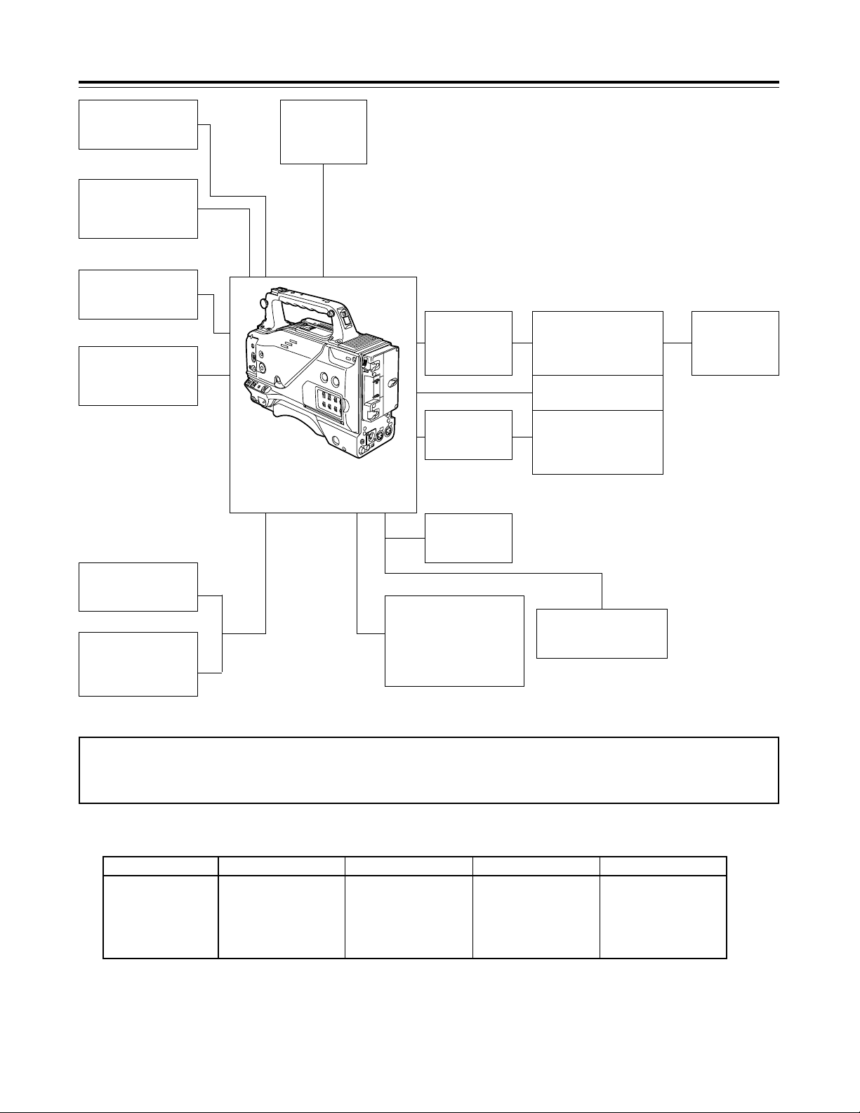
System configuration
Mic kit:
AJ-MC700
Wireless mic
receiver:
WX-RJ700
Mic holder:
AJ-MH700
Lens (bayonet type):
FUJINON/CANON
Rain cover:
SHAN-RC700
Soft carrying case:
AJ-SC900
Battery case:
AU-M402H
Battery
case/holder
AC adapter:
AJ-B75
Cassette tapes:
AY-DV124MQ
AY-DV124PQ
AY-DV186MQ
AY-DV186PQ
AY-DV276MQ
Cleaning tape:
AY-DVCL
Battery
chargers:
AG-B425
AJ-B450
Panasonic batteries:
AU-BP402
AJ-BP490
Anton Bauer batteries
Sony batteries:
BP-90
BP-L60/L90
NP-1B
1/5˝ viewfinder:
AJ-VF10
AJ-VF15
Digital Video Camera Recorder
AG-DVC200
<Note> Checking the lens shading compensation
This unit comes with a function which provides shading compensation for the lens. Check that the compensation is optimum for the type
of lens used. For further details, refer to “Lens adjustments and checks” (page 15).
Lens classification
Lens type
A B
S18 k 6.7BERM4
S18 k 6.7BRM4
S19 k 6.5BERM4
S19 k 6.5BRM4
YH18 k 6.7IRS
YH12 k 4.8IRS
YH18 k 6.7KRS
YH14 k 7.3KRS
YH12 k 4.8KRS
S14 k 7.5BRM4
S17 k 6.6BRM4
C
S14 k 7.3BRM
(For AG-DVC200D)
USER
Lens other than A, B or C
Lens shading compensation data selection
Page 6
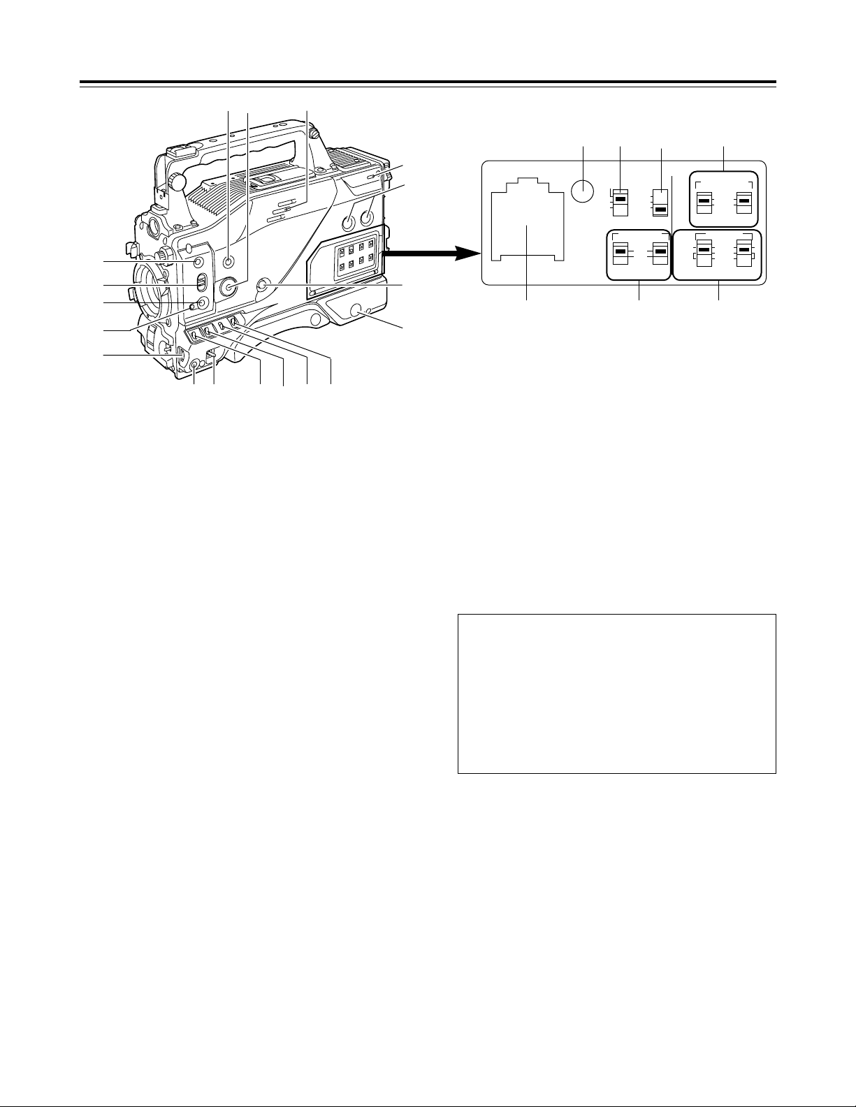
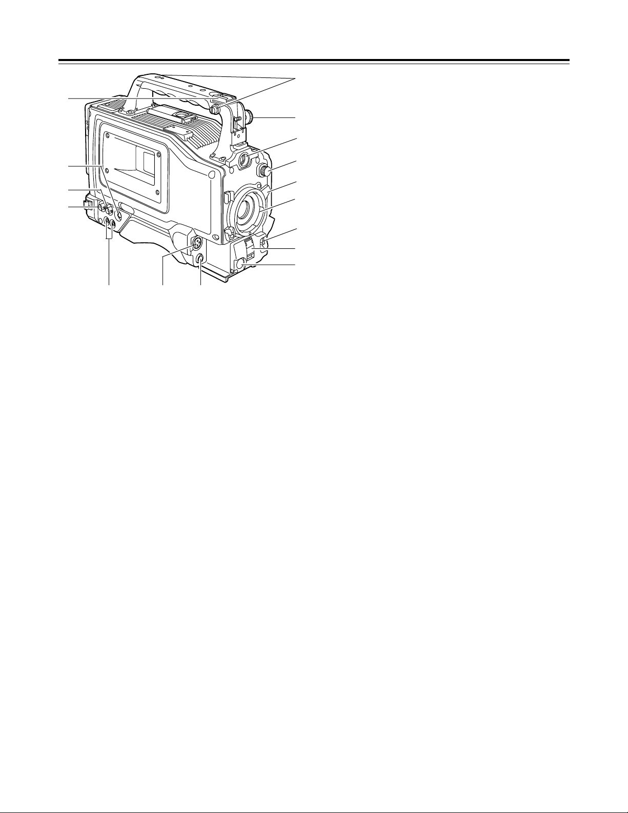
Parts and their functions
1
POWER switch
This switch turns the power ON and OFF.
4
OUTPUT/AUTO KNEE selector switch
This switch selects the video signals which are to be output from
the camera unit to the VTR unit, viewfinder and/or video
monitor.
CAM, AUTO KNEE ON:
The images shot by the camera are output. The AUTO
KNEE circuit operates.
CAM, AUTO KNEE OFF:
The images shot by the camera are output. The MANUAL
KNEE circuit operates.
BARS:
Color bar signals are output. The AUTO KNEE circuit does
not operate.
1B
<:
@
;
9
A
?
=
>
8
6
7
5432
3
GAIN selector switch
When the camera screen is dark, turn this switch to a position
which will increase the gain and brighten the screen.
The gain for each item can be selected on-screen. For further
details, refer to the table for <SW MODE> in the section on the
setting menu screens (page 33).
L: The switch is normally set to this position. The gain at this
position was set to 0 dB at the factory prior to shipment.
M:The gain of the camera’s video amplifier is increased. The
gain at this position was set to 9 dB at the factory prior to
shipment.
H:The gain of the camera’s video amplifier is increased even
more. The gain at this position was set to 18 dB at the
factory prior to shipment.
2
VTR STBY/SAVE (tape protection) switch
This switches the power supply mode when the VTR is set to
the rec pause mode in which recording is temporarily
suspended.
STBY:In this mode, recording starts immediately by pressing
the VTR START button.
SAVE:This is the tape protection mode. The tape drum is
stopped in the half-loading status. Less power is
consumed at this position than at the STBY position so
that the battery will supply power to the unit for a longer
period of time.
Compared with the STBY position, more time is taken to
start recording after the VTR START button is pressed.
When the switch is set to the SAVE position, the VTR
SAVE lamp inside the viewfinder lights up.
<Note>
When the PAUSE TIMER time has elapsed in the STBY mode,
the unit is automatically set to the SAVE mode. For further
details, refer to the table for <VTR OPTION> in the section on
the sub-menu screens (page 34).
AUTO KNEE function
When shooting with the level set to people or scenes against a
high-brightness background, the background will be whitened
out, and the buildings and scene in the background will be
blurred. If the AUTO KNEE function is activated at times like
this, the background will be reproduced clearly. This function
is effective for shooting in the following situations:
≥When shooting people in the shade under a clear sky
≥When simultaneously shooting people in a car or indoors
and the outside scenery through a window
≥When shooting scenes with a strong contrast
6
RESET
COUNTER AUDIO SELECT
AUDIO IN
AUTO
MIC
FRONT
REAR
MIC
LINE
MAN
TCG
TC
UB
ON
OFF
CH1 CH1 CH2
CH1
CH2
CH2
F-RUN
SET
R-RUN
MIC POWER
G
DC E F
HI
5
WHITE BAL (white balance memory
selector) switch
A or B:When the AUTO W/B (white/black) BAL switch on the
front panel is operated to adjust the automatic white
balance, the adjusted value is automatically stored in A
or B.
PRST: The color temperature is set to 3200K in the preset
mode. The AUTO W/B BAL switch does not work at this
position.
<Reference>
The automatic tracking white balance mode (ATW) can be set to
A, B or PRST. For further details, refer to the table for <SW
MODE> in the section on the sub-menu screens (page 33).
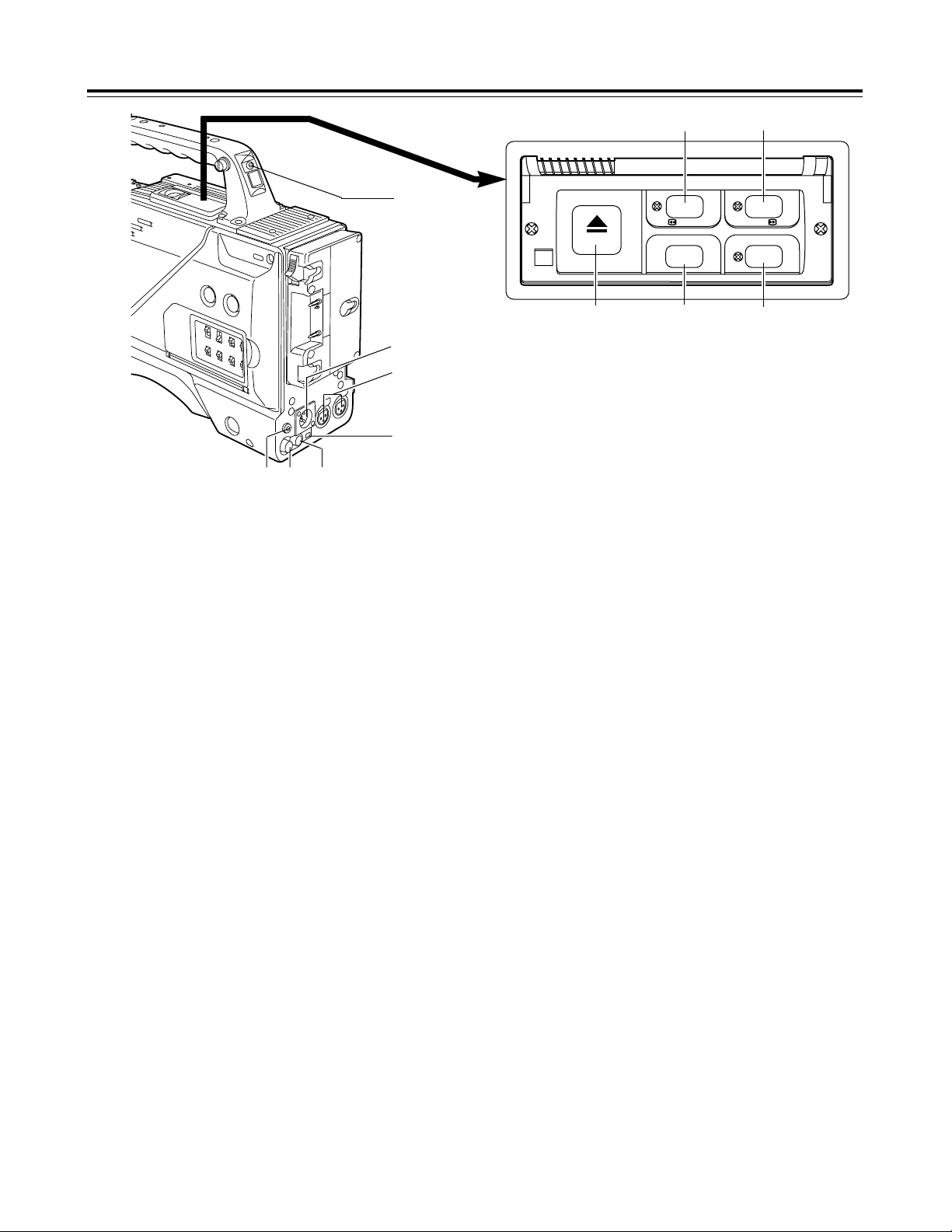
Page 7

7
Parts and their functions
B
MENU button
This is used to switch the menu ON and OFF.
A
JOG dial button
This is used to select the menu items and perform settings when
the MENU button B is at the ON position. When the synchro
scanning mode has been selected for the shutter speed, the
shutter speed can be easily adjusted more finely.
?
FULL AUTO button
This is pressed when there is no time to check the camera unit’s
settings. The lens iris and white balance will be automatically
adjusted.
@
FULL AUTO lamp
This lights up when FULL AUTO shooting is being performed.
>
AUTO IRIS MODE selector switch
This is used to select the position that matches the shooting
conditions when shooting by automatically adjusting the lens
iris.
BACK.L : When making a back-lit subject brighter for shooting
STD :For normal shooting
SPOT.L : For shooting a spot-lit subject
=
QUICK FOCUS button
This supports the focusing of the subject. When it is pressed,
the lens iris is opened for about 10 seconds. It makes the depth
of field shallower and facilitates focusing.
<
MODE CHECK button
This enables the setting modes of the camera’s control switches
to be checked in the viewfinder.
;
SCENE FILE dial
This enables the camera settings that match the shooting
conditions to be selected. For further details, refer to “How to
use file select” (page 24).
:
SPEAKER
The sound can be monitored through this speaker.
When an earphone is connected to the PHONE jack, the sound
of the speaker will be automatically cut off.
What can be monitored is the mixed sound of CH1 and CH2.
7
MONITOR (volume) control
This is used to adjust the volume of the monitor speaker or
earphone.
8
AUDIO LEVEL CH1, CH2 (audio channel 1,
2 recording level) controls
These are used to adjust the CH1 and CH2 recording levels
while monitoring the level meter inside the viewfinder.
9
POWER/WARNING lamp
This lamp lights up green when the power is turned on, and it
flashes in green during interval recording. When a warning is
given, it lights up red or flashes in red to alert the user. For
further details, refer to “Warning system” (page 38).
6
BREAKER switch
If an excessively high current flows inside the unit due to some
problem or other, the circuit breaker is tripped and the power is
automatically turned off to protect the unit.
Push this button in after conducting an inspection or repairs
inside the unit. If there are no problems, the power will come
back on.
D
COUNTER selector switch
This is used to switch the counter display.
COUNTER: A relative numerical value is displayed by the
counter. However, when the tape recording
includes discontinuous parts, the counter reading
may also lack continuity.
TC : The time code is displayed.
UB :The user’s bit is displayed.
E
TCG selector switch
This sets the time code operation mode to FREE RUN, REC
RUN or SET. For further details, refer to “Setting the time data”
(page 22).
F
AUDIO SELECT CH1, CH2 (audio channel 1,
2 auto/manual level adjustment selector)
switches
Page 8
8
Parts and their functions
4
1
2
3
=
@
5
6
>
789
:
?
;
<
4
AUTO W/B (white/black) BAL switch
AWB:The white balance is automatically adjusted. When the
AWB memory selector switch on the side panel is set to A
or B and then the AUTO W/B BAL switch is operated, the
adjustment value is recorded in the memory. Bear in
mind that the switch does not work when it is set to the
ATW or PRST position.
ABB: The black balance is automatically adjusted.
1
CC/ND filter selector knob
This is used to select the filter to match the subject brightness.
1 :3200K
2 :5600K+1/8ND
3 :5600K
4 :5600K+1/64ND
5
SHUTTER switch
This is the ON/OFF selector switch of the electronic shutter.
OFF: The electronic shutter does not operate.
ON : The electronic shutter operates.
SEL: This is used when the electronic shutter speed is to be
changed. The switch is a non-locking type. The shutter
speed changes each time it is operated. For further
details, refer to “Electronic shutter settings” (page 21).
6
VTR START/STOP button
This starts or stops the video recording.
3
Lens mount (bayonet type)
The lens is attached to this mount.
7
LENS jack (12-pin)
The connecting cord of the lens is connected to this jack. For
further details on the lenses that can be used, refer to the
operating instructions of the lenses concerned.
8
MIC IN (mic input) jack (XLR, 3-pin)
The accessory microphone is connected to this jack. The power
for the microphone is supplied from this jack.
2
Lens lever
This lever is tightened to secure the lens after the lens has been
attached to the lens mount.
:
GENLOCK IN connector (BNC)
Supply the sync signal (black burst signal) to this connector
when gen-locking the camera pictures (CAM OUT jack) of the
unit.
9
AUDIO OUT jacks (pin jacks)
An audio component is connected to these jacks. The sound for
channel 1 and channel 2 is output separately.
>
Viewfinder stopper screw
This screw is used to secure the viewfinder.
?
Light shoe
The video light or other such device is attached here.
@
Shoulder belt fittings
The shoulder belt (optional accessory) is attached here.
<
S-VIDEO OUT jack (Y/C jack)
When pictures are to be recorded with a backup VTR connected
to the S-VIDEO OUT jack, bear in mind that the unit’s playback
pictures will be recorded onto the backup VTR if any operation
(such as REC CHECK) that performs VTR playback is
executed.
;
CAM OUT jack
This is the dedicated output jack for the camera’s pictures.
=
Viewfinder connector
The viewfinder plug is connected to this connector.
Page 9
9
Parts and their functions
2
External DC input socket
This is the input socket of the external power supply (DC power
supply). When an AC adapter is connected here, power is
automatically supplied from the external source.
3
AUDIO IN CH1, CH2 (audio input channel 1,
2) jacks (XLR, 3-pin)
An external microphone or line input signals are connected to
these jacks.
5
DC OUT (DC power supply) output socket
This normally serves as the DC 12 V output socket. A current of
approximately 1 A can be taken out.
When the HDD adapter scheduled to be developed in the future
is connected here, it will be possible to supply a 7 V voltage.
6
VIDEO OUT jack (BNC)
This is the composite video jack for a monitor.
<Note>
When pictures are to be recorded with a backup VTR connected
to the VIDEO OUT jack, bear in mind that the unit’s playback
pictures will be recorded onto the backup VTR if any operation
(such as REC CHECK) that performs VTR playback is
executed. Use the exclusive camera output jack for backup
recording.
7
PHONES (earphones) jack (mini jack)
The earphones (stereo) for monitoring sound are plugged in
here. When the earphones are connected, no sound will be
output from the speaker.
1
TALLY lamp
This lights up when the unit is set to the recording mode. It
flashes when it is being transferred to the recording mode.
4
DV I/F connector (complying with IEEE
1394 standard)
A digital video component or computer equipped with a DV
connector is connected to this connector using a DV cable
(optional accessory). For further details, refer to “Using the unit
with external components” (page 29).
1
2
3
4
67
5
9
8
:;
8
REW (rewind)/FF (fast forward) buttons/
lamps
≥When one of these buttons is pressed in the stop mode, the
high-speed playback (rewind or fast forward) mode is
established, and the corresponding lamp lights.
≥When one of these button is pressed in the playback mode,
the 4a speed playback (rewind or fast forward) mode is
established, and when the same button is pressed again, the
8a speed playback (rewind or fast forward) mode is
established.
Each time the button is then pressed, the mode is switched
between 4a speed playback and 8a speed playback.
≥When one of these buttons is pressed in the STILL or REC
PAUSE mode, the 1a speed playback (rewind or fast forward)
is established while the button is held down. When the button
is released, the unit returns to the previous mode (STILL or
REC PAUSE).
The variable speed playback mode is released by pressing the
STOP button, PLAY/PAUSE button or EJECT button.
9
STOP button
The tape stops traveling when this button is pressed. However,
the button cannot be operated during recording. To stop
recording, first set the unit to the REC/PAUSE mode, and then
press the STOP button.
:
PLAY/PAUSE button/lamp
Playback commences when this button is pressed, and the lamp
lights. When it is pressed again, the STILL mode is established,
and the lamp flashes.
When it is pressed once more, the playback mode is restored.
;
EJECT button
When this button is pressed, the cassette holder rises, and the
cassette tape can be inserted or removed. This button cannot
be operated while the unit is recording, in which case first set
the unit to the REC/PAUSE mode, and then press the EJECT
button.
8
6
/
REW FF
EJECT
STOP PLAY/PAUSE
ª
5
/
1/;
Page 10
Page 11
11
Preparation
Using a battery pack made by Anton Bauer
1
Attach the battery pack made by Anton
Bauer.
2
Insert the battery pack and slide it in the
direction of the arrow.
Power output connector for lighting
Battery pack made by Anton Bauer
Before use, charge the battery pack using the exclusive battery
charger made by Anton Bauer.
For the charging time and other details, refer to the operating
instructions of the battery charger used.
Lighting control switch
<Reference>
A battery holder made by Anton Bauer is equipped with a power
output connector for the lighting and a lighting control switch to
enable a light to be easily attached. For details on the lighting
systems available, contact Anton Bauer.
3
Set the battery type.
Select the battery type using <BATTERY> on the sub-menu
screen.
Example: Select “NiCd13” if the TRIMPAC13 is to be used;
select “NiCd14” if the TRIMPAC14 is to be used.
(See page 34)
3
Set the battery type.
Select the battery type using <BATTERY> on the sub-menu
screen.
Select “NiCd12” if the NP-1B is to be used. (See page 34)
<Reference>
To remove the battery pack, slide it in the opposite direction to the
one in which it was attached while keeping the release lever on the
battery holder pulled down all the way.
Release lever
2
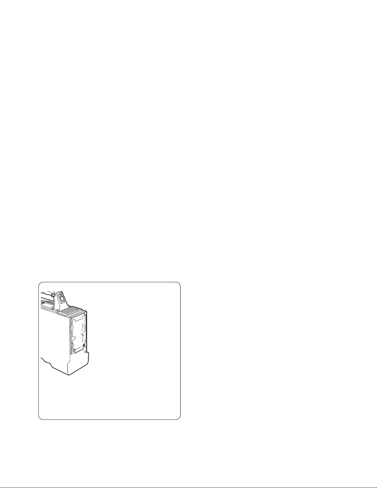
Using the NP-1B battery pack made by Sony
Before use, charge the battery pack using the exclusive battery
charger made by Sony.
For the charging time and other details, refer to the operating
instructions of the battery charger used.
Refer to step 1 on page 10.
1
Remove the battery holder.
2
Attach the battery made by Sony to the
unit.
Screw provided
with mounting
connector for
NP-1B
Mounting
connector for
NP-1B
Cover
2
1
3
4
5
Battery case
Hole
First, remove the battery holder cover.
1 Attach the mounting connector for the NP-1B.
2 Use the mounting screws to mount the battery case.
3 Tighten the screw for the power supply contact.
4 Insert the top of the cover in the direction of the arrow.
5 Align the hole in the bottom of the cover (metal part) with the
hole in the bottom of the battery case, and attach using the
screw provided with mounting connector for NP-1B.
Page 12
12
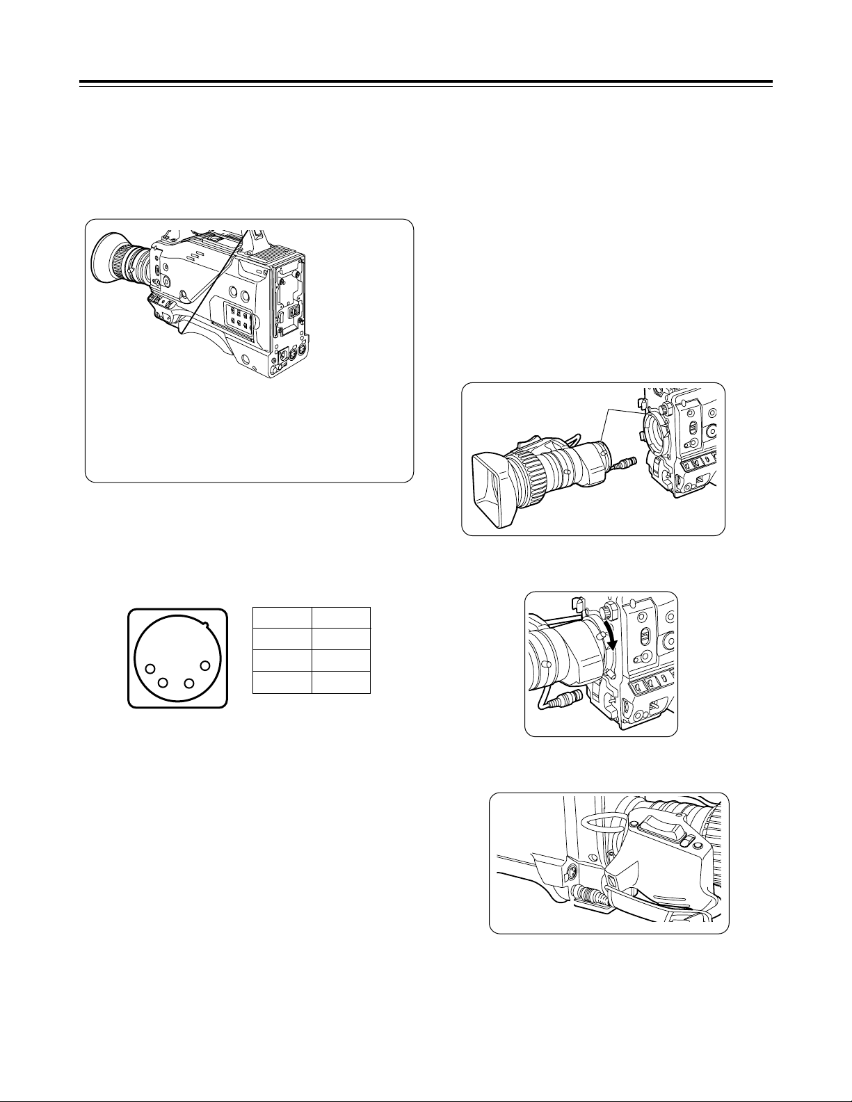
Attaching the lens
1
Raise the lens lever, and remove the
mount cap.
4
Push the cable into the cable clamp, and
connect it to the LENS jack.
Mark
3
Pull down the lens lever to secure the
lens.
LENS jack
<Notes>
≥For details on how to handle the lens, refer to the operating
instructions of the lens.
≥While the lens is removed, attach the mount cap to protect the
unit.
Preparation
Using an AC power supply (with the AJ-B75 AC adapter)
1
Connect the unit’s external DC input
socket with the DC OUT socket on the AJB75 AC adapter.
2
Turn on the AC adapter’s power.
5
Proceed with the flange back adjustment
for the lens.
3
Set the unit’s POWER switch to ON.
When an AC adapter other than the AJ-B75 is to be used,
check the pin signals of the external DC input socket.
<Notes>
≥When both a battery pack and an AC adapter have been
connected, the power supplied from the AC adapter takes priority.
It is also possible to attach/remove a battery while the AC adapter
is being used.
≥When an AC adapter is to be used, the unit’s POWER switch must
be set to ON only after the AC adapter’s power has been turned
on. If the power is switched on in the reverse sequence, the AC
adapter’s output voltage will rise slowly, possibly causing the unit
to malfunction.
Pin No Signal
1 GND
2, 3 –
4 +12 V
1
2
3
4
External DC input socket
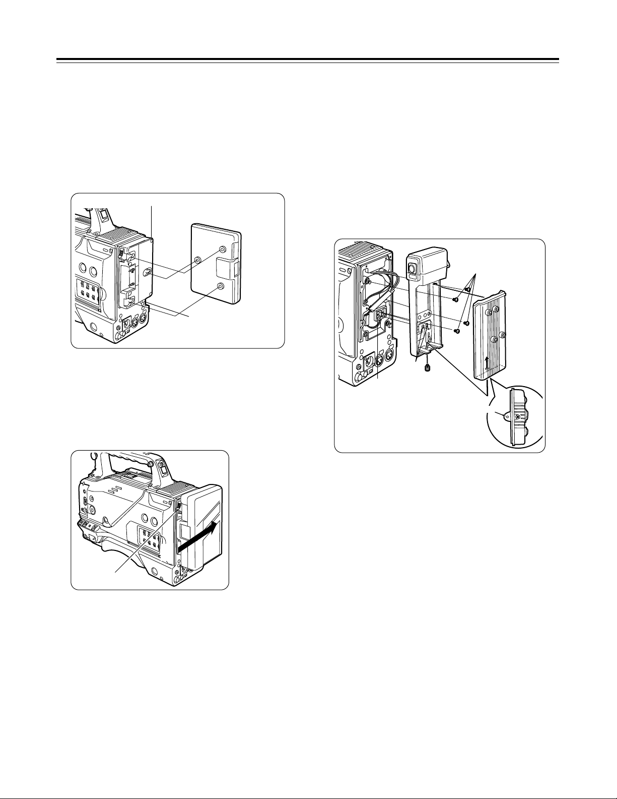
Page 13
13
Preparation
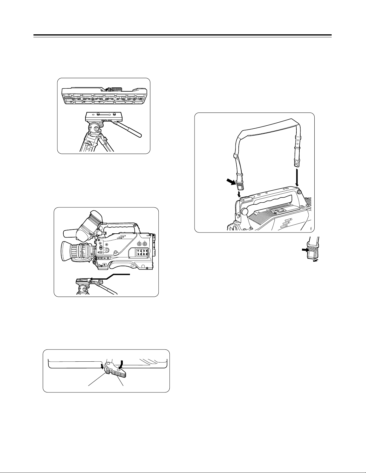
Tripod attachment
Mounting the unit on a tripod
1
Mount the tripod attachment on the tripod.
Use the tripod attachment to mount the unit on a tripod.
For details on the attachment and adjustments of the viewfinder and
microphone, refer to the operating instructions of the viewfinder.
<Note>
Take account of the center of gravity of the unit and that of the
tripod attachment when selecting the attachment hole. Check that
the diameter of the hole selected matches the diameter of the tripod
head screw.
2
Mount the unit on the tripod attachment.
Slide the unit along the groove toward the front until it clicks into
place.
Tripod head
Tripod attachment
Detaching the unit from the tripod attachment
Red lever
While pushing down the red lever, move the black lever in the
direction of the arrow and slide the unit toward the back to remove
it.
<Note>
If the pin of the tripod attachment fails to return to its original
position after the unit has been detached, again move the black
lever in the direction of the arrow while pushing down the red lever,
and return the pin to its original position. Bear in mind that the unit
cannot be attached if the pin remains in the center.
Black lever
Attaching the shoulder belt (optional accessory)
Attaching the viewfinder and microphone
Shoulder belt
The tab opens
when it is
pressed.
<Note>
Check that the shoulder belt is attached securely.
To disengage the shoulder belt,
open the tabs of the attachment
parts, and disengage.
The tab opens
when it is
pressed.
Page 14

14
Preparation
Setting the camera ID
The camera ID is set on the <CAMERA ID> screen. Up to 12
alphanumerics, symbols and spaces can be used.
<Note>
The camera ID does not appear while the setting menu is displayed
even when color bar signals are output.
<Note>
The camera ID input above will be recorded at the same time as the
color bar signals.
1
Proceed with the sub-menu operation
(page 30), and open the <CAMERA ID>
screen.
4
Keep turning the JOG dial button until the
character to be set appears.
6
Turn the JOG dial button to move the
arrow (cursor) to the next position (on the
right), and repeat steps 3, 4 and 5 to enter
the remaining characters.
5
Press the JOG dial button to enter the
character.
7
Press the MENU button to end the menu
operation.
#3
< CAMERA ID >
CAMERA ID:ID
ID:
¢¢¢¢¢¢¢¢¢¢¢¢
2
Turn the JOG dial button to move the
arrow (cursor) to the ID item.
3
When the JOG dial button is pressed, the
arrow (cursor) flashes to signal that the
input mode has been established.
3
< CAMERA ID >
CAMERA ID:ID
v
#
ID:
¢¢¢¢¢¢¢¢¢¢¢¢
When the button is turned, the character display is switched in
the following sequence:
Space: ∏
7
Letters of the alphabet: A through Z
7
Numbers: 0 through 9
7
Symbols: ', >, <, /, -
The setting menu is cleared, and the unit’s current status is
displayed.
To change the ; back to >, press the JOG dial button when
the ; is above the colon (:).
Setting the date and time
1
Proceed with the sub-menu operation
(page 37) to open the <TIME/DATE> screen.
#3
< TIME/DATE >
YEAR :01
MONTH :01
DAY :01
HOUR :00
MINUTE :00
TIME/DATE SET:READY
2
Turn the JOG dial button to select the item
to be changed, and press the JOG dial
button.
3
< TIME/DATE >
YEAR :01
MONTH :01
DAY :01
HOUR :00
#
MINUTE :00
TIME/DATE SET:READY
4
When the setting is completed, turn the
JOG dial button to select TIME/DATE SET,
and press the button.
3
< TIME/DATE >
YEAR :01
MONTH :01
DAY :01
HOUR :00
MINUTE :00
#
TIME/DATE SET:OK
3
Turn the JOG dial button to change the
setting, and then press the button to enter it.
The READY display changes from ACTIVE to OK, and the
clock function starts operating.
The setting menu is cleared, and the unit’s current status is
displayed.
5
Press the MENU button to end the menu
operation.
<Note>
≥The seconds cannot be set. The time always starts from zero
seconds.
≥At normal temperature with the power off, the clock will have an
accuracy of ±30 seconds/month. When accurate time is
necessary, check the time with the power on and reset to the
correct time.
Page 15
15
Lens adjustments and checks
The flange back (distance from the lens mounting surface to the
image formation surface) is adjusted when a subject cannot be
brought into focus precisely using either the telephoto or the wide
angle positions when performing zoom operations.
Once the flange back has been adjusted, it need not be re-adjusted
unless the lens is replaced. For details on the adjustment method
and lens positions, refer to the operating instructions of the lens
concerned.
Flange back adjustment
<Note>
Coloring may occur in the vertical direction near the open setting of
the lens iris even when the white shading has been adjusted. This
phenomenon is a characteristic inherent to lenses and optical
systems, and it is not indicative of a failure.
White shading adjustment
This unit enables the fixed data supporting three types of lens and
the data supporting any desired adjustments to be used for white
shading compensation. This data can be selected using LENS
SHADING on the sub-menu (see page 35).
First, check that the type of lens used and the settings match. The
fixed data settings are as follows:
Type A: Data for S18 k 6.7BERM4 (etc.) lenses.
Type B: Data for YH18 k 6.7KRS (etc.) lenses.
Type C: Data for S14 k 7.3BRM lens.
If the lens to be used does not correspond to any of these types,
proceed to adjust the white shading described below by performing
menu operations.
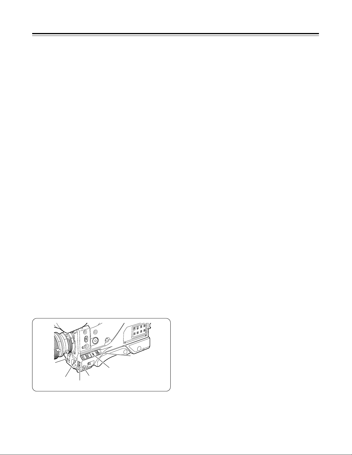
White shading check
SHUTTER
switch
GAIN: L (0 dB)
AWB memory
selector switch
AUTO W/B BAL
switch
1
Proceed with the camera settings for the
adjustment.
4
Repeat the operation in step 2-22.
JOG dial button
MENU button
2
Proceed with the image settings.
1 Shoot a piece of paper with no color unevenness.
2 Set the lens iris to manual, and adjust it so that a zebra
pattern fills the whole screen. Check that the lens iris is
between f/4 and f/11.
<Notes>
≥Flicker tends to occur under fluorescent lights, mercury lamps
and other such lighting conditions. Use sunlight, halogen
lamps or a light source which rarely give rises to flicker.
≥If there is unevenness in the lighting, the zebra pattern will no
longer appear on some parts of the screen. In this situation,
adjust the lighting position, etc.
≥Adjust the lighting position, etc. also when the lens iris is not
between f/4 and f/11.
≥The electronic shutter must be left at the OFF setting.
3
Adjust the white balance and black
balance.
1 Set the WHITE BAL selector switch to A or B, and use the
AUTO W/B BAL switch to execute the automatic white
balance adjustment (AWB).
2 Use the AUTO W/B BAL switch to execute the automatic
black balance adjustment (ABB).
3 Once again, use the AUTO W/B BAL switch to execute the
automatic white balance adjustment (AWB).
1 Mount the lens on the camera.
Do not forget to attach the lens cable.
2 Set the electronic shutter to OFF and the gain to L (0 dB).
3 If the lens comes with an extender, disengage the extender
function.
4 Proceed with the menu operation (page 30) to open the sub-
menu <LENS SHADING> screen, and set “LENS SELECT”
to USER.
5
Proceed with the white shading
adjustment.
1 Proceed with the menu operation (page 30), and open the
sub-menu LENS SHADING screen.
2 Turn the JOG dial button to align the cursor with LENS
SELECT, and press the button. Then turn the JOG dial
button further to align the cursor with USER, and press the
button to select this item.
3 Use the JOG dial button to align the cursor with SHADING
(USER), and select this item.
ACTIVE appears on the screen to indicate that the white
shading is being automatically adjusted. The adjustment is
completed when the ACTIVE display is cleared and OK
appears.
4 Press the MENU button to close the menu screen.
6
If the lens comes with an extender, engage
the extender function, and repeat steps 2
through 5.
Page 16

EX TAPE NEAR END FLUO.
48K
CH2
iREC TCG 12:34:56:00
0
dB
1100 LOW LIGHT
DJan-01-01 23:59:00
=========
¢¢¢
min
13.4V
Z78
ATW
F56
CH1
AWB+02
32K
.
.
SPOT QUICK FOCUS
¢1¢¢¢¢¢¢¢¢¢¢¢¢¢¢¢¢
¢2¢¢¢¢¢¢¢¢¢¢¢¢¢¢¢¢
FL1
/
2
1
<
4
5
6
7
8
9
:
;GHF
D
E
C
B
A
@
?
>
=
I
16
EX TAPE NEAR END FLUO.
48K
CH2
TCG 12:34:56.00 NDF
SHUT :OFF SKIN :OFF
!¢¢¢¢¢¢¢¢¢¢¢¢
DJan-01-01 23:59:00
=========
¢¢¢
min
13.4V
WHITE :A 3.6K
KNEE :MANUAL A.IRIS:BACK
SCENE F1:FLUO.
GAIN :0dB GAMMA :NORMAL
FILTER:1 COLOR :+10
CH1
Viewfinder displays
REC
BATT
VTR
SAVE
1
3
234
In addition to the images, messages indicating the unit’s settings
and the operation mode appear on the viewfinder screen.
Also displayed are the center marker and safety zone markers.
At the top, bottom and right edges of the screen are the items which
have been set to ON using the sub-menu <MARKER/ZEBRA>, <VF
DISPLAY 1/2> and <VF DISPLAY 2/2> screens or the switches
relating to the viewfinder displays. When a setting has been
changed or an adjustment is made, a message informing the user
of the setting details, adjustment transition status and adjustment
result is displayed for about 3 seconds.
For further details, refer to the items concerned on the sub-menu
<MARKER/ZEBRA>, <VF DISPLAY 1/2>, <VF DISPLAY 2/2>,
<!LED>, <CAMERA ID> and <TIME DATE> screens.
J
J
The displays shown in the example are those of the AJ-VF10.
(For details on the viewfinder, refer to the operating instructions of
the viewfinder available as an optional accessory.)
1
REC (record) lamp
This lights up red during recording. It flashes when an error has
occurred. For further details, refer to “Warning system” (page
38).
3
BATT (battery) lamp
This starts flashing several minutes before the battery voltage
drops to the level where the battery can no longer be used, and
it remains lighted when the battery can no longer be used. To
prevent an interruption to operation, replace the battery before
the battery becomes completely discharged. For further details,
refer to “Warning system” (page 38).
Viewfinder lamp displays
Viewfinder screen status displays
Status displays on the viewfinder screen when the
MODE CHECK switch is ON (normal)
EX TAPE NEAR END FULL
48K
CH2
TCG 12:34:56.00 NDF
!¢¢¢¢¢¢¢¢¢¢¢¢
DJan-01-01 23:59:00
=========
¢¢¢
min
13.4V
FULL AUTO
FILTER:1
SCENE F1:FLUO.
GAMMA :NORMAL
SKIN :OFF
CH1
Status displays on the viewfinder screen when the
MODE CHECK switch is ON (FULL AUTO)
2
(irregular operation status warning) lamp
This lights up when the unit is placed in an irregular operation
status for any of the items set to ON in the sub-menu <!LED>.
For details on selecting the items subject to the lamp
display, refer to sub-menu <!LED> (page 37).
4
VTR SAVE (VTR power-saving) lamp
This lights up when the VTR SAVE/STBY switch is set to SAVE.
It goes off during recording.
<Note>
After the period set for the pause timer is exceeded during Rec
Pause, or after 1 minute has passed during Pause (Still), the
unit will automatically switch to SAVE mode and the lamp will
light, regardless of the VTR SAVE/STBY switch position.
Page 17

17
Displayed when the AWB has been attained for channel A.
Displayed when the AWB has been attained for channel A, and the color
temperature is lower than the display range.
Displayed when the AWB has been attained for channel A, and the color
temperature is higher than the display range.
Displayed when the AWB has been attained for channel B.
Displayed when the AWB has been attained for channel B, and the color
temperature is lower than the display range.
Displayed when the AWB has been attained for channel B, and the color
temperature is higher than the display range.
Displayed when AWB has been switched to PRE.
Displayed when AUTO KNEE has been changed from OFF to ON.
Displayed when AUTO KNEE has been changed from ON to OFF.
Displayed when the gain has been switched.
Displayed when the filter has been switched.
Displayed when the shutter has been set to OFF.
Displayed when the shutter has been set to ON.
Displayed when the IRIS MODE switch setting has been changed.
Displayed when FULL AUTO has been changed from OFF to ON.
Displayed when FULL AUTO has been changed from ON to OFF.
Displayed when the scene file dial setting has been switched.
Viewfinder displays
Display item What is displayed Status causing the display to appear
3 Time code display
TCG 12:59:59:29
TCR 12:59:59:29
UBG AB:CD:EF:00
UBR AB:CD:EF:00
CNT 01:59:59
Indicates the TCG (time code generator) value.
Indicates the TCR (time code reader) value.
Indicates the UBG (user’s bit generator) value.
Indicates the UBR (user’s bit reader) value.
Indicates the COUNTER (counter) value.
1 Extender display
EX Displayed when the lens extender is being used.
4 Center marker
+ Displayed when ON is selected as the CENTER MARK setting (see page
35). It indicates the center of the viewfinder screen.
2 INTERVAL REC
status display
iREC Indicates the interval recording mode. For further details, refer to
“INTERVAL REC function” (page 28).
5 1st line message
display (changes in
switch settings)
AWB Ach ¢.¢K
AWB Ach ¢.¢K UNDER
AWB Ach ¢.¢K OVER
AWB Bch ¢.¢K
AWB Bch ¢.¢K UNDER
AWB Bch ¢.¢K OVER
AWB PRE ¢.¢K
AUTO KNEE ON
AUTO KNEE OFF
GAIN ¢¢dB
FILTER ¢
SHUTTER OFF
SHUTTER 1/¢¢¢¢
IRIS MODE ¢¢¢¢
FULL AUTO ON
FULL AUTO OFF
SCENE FILE USER
SCENE FILE 1
SCENE FILE 2
SCENE FILE 3
SCENE FILE 4
SCENE FILE STD
(AWB, ABB operation
displays)
AWB ACTIVE
AWB OK ¢.¢K
AWB OK ¢.¢K UNDER
AWB OK ¢.¢K OVER
AWB NG
AWB PRE
ATW MODE
ABB ACTIVE
ABB OK
ABB NG
Displayed while the AWB operation is in progress.
Displayed when AWB is completed error-free.
Displayed when AWB is completed error-free, and the color temperature is
outside the display range (under ¢.¢K).
Displayed when AWB is completed error-free, and the color temperature is
outside the display range (over ¢.¢K).
Displayed when AWB is completed with an error.
Displayed when AWB cannot be performed because AWB is set to PRE.
Displayed when ATW (full time auto white balance) is in progress.
Displayed while the ABB operation is in progress.
Displayed when ABB is completed error-free.
Displayed when ABB is completed with an error.
5 2nd line message
display
(error result message
displayed after AWB
or ABB has been
performed)
color temp LOW
color temp HIGH
LEVEL OVER
LOW LIGHT
UNSTABLE CONDITION
TIME OVER
Warns that the color temperature is too low during the AWB operation.
Warns that the color temperature is too high during the AWB operation.
Warns that the brightness is too high during the AWB operation.
Warns that the brightness is too low during the AWB operation.
Warns that the screen is not stable during the AWB or ABB operation.
Warns that the AWB or ABB processing could not be completed within the
allotted time.
6 IRIS MODE switch
status display
SPOT
BACK
Displayed when the IRIS MODE switch is at the SPOT.L position.
Displayed when the IRIS MODE switch is at the BACK.L position.
7 QUICK FOCUS
display
QUICK FOCUS Displayed when QUICK FOCUS is ON.
Page 18

18
E Calendar/clock
display
Jan-01-01 00:00:00 The 24-hour system is used for the clock display.
(Month-day-year and hours-minutes-seconds displayed)
F Voltage display
BAR display
¢¢.¢V
B ∫∫∫∫
The input voltage is displayed.
The number of “∫” squares serves as a rough guideline to indicate how
much battery charge remains. When the battery still has a sufficient charge,
four of these squares are displayed. These squares can be displayed
except when Type A or Type B has been selected as the <BATTERY
SELECT> setting on the BATTERY sub-menu. (See page 34)
Viewfinder displays
; Audio level meter
display
Indicates the audio levels of CH1 and CH2 (see page 27).
Display item What is displayed Status causing the display to appear
9 LOW LIGHT warning
display
LOW LIGHT Displayed when the brightness has been reduced.
@ AWB color
temperature display
¢.¢K
Indicates the color temperature.
8 Shutter speed 1/¢¢.¢
1/100 - 1/2000
SUPER V
Displayed when the shutter speed has been set to SYNCHRO SCAN.
Displayed when a fixed shutter speed has been set.
Displayed when SUPER V (high vertical resolution mode) has been set.
: AUDIO sampling
frequency display
48k
32k
Indicates that a frequency of 48 kHz has been selected.
Indicates that a frequency of 32 kHz has been selected.
<Note>
With a 1394 input, the input status is displayed.
> AWB color
temperature fine
adjustment amount
display
AWB+¢¢
The adjustment amount is displayed when ON has been selected as the
“COLOR TEMP” setting (see page 36) and the color temperature has been
adjusted finely. It is not displayed when OFF is selected or only ATW has
been set.
? Zoom display
Z00 - Z99 Indicates the zoom amount. However, most 1/2-inch size lenses have no
zoom position return. In such a case, this item is not displayed even if ON
has been selected as the display setting.
A ATW, AWB channel
display
Ach
Bch
PRE
ATW
The WHITE BAL switch has been set to channel A.
The WHITE BAL switch has been set to channel B.
The WHITE BAL switch has been set to PRE.
The full time auto white balance has been set.
B F value display
NC
OPEN
F2.0 - F16
CLOSE
Displayed when the lens cable has not been connected.
Displayed when the lens iris has been opened.
Indicates the lens iris value.
Displayed when the lens iris has been closed.
<Note>
This item appears when using a lens equipped with a function that displays
the aperture value.
= FULL AUTO/SCENE
FILE display
FULL
Filename which has been set
Displayed when the FULL AUTO switch has been set to ON.
Indicates the filenames (8 characters) set for the scene files.
< VTR warning
display/voltage
warning display
REC WARNING
SLACK E-¢¢
HUMID
SERVO
RF
TAPE NEAR END
TAPE END
BATT NEAR END
BATT END
MP TAPE
BACKUP BATT EMPTY
Indicates the occurrence of an error during recording.
Indicates the occurrence of an error caused by the mechanism. Depending
on the type of error, the power may be cut off automatically.
<Note>
For details on the codes displayed, refer to “Error codes” (page 40).
Indicates that condensation has formed.
Servo lock is not engaged during recording or playback.
The signal level from the tape has dropped.
The tape is nearing its end (there are about 2 minutes left).
The tape has stopped at the tape end.
The battery is nearly flat.
The tape has stopped because the battery is flat.
An MP tape has been loaded. The tape is automatically ejected.
It is time to replace the backup battery.
C Gain display
0 - 36dB Displays the current gain value.
D Filter display
FL1 - FL4
FL–
Displays the filter position.
Displayed when filter has not been set to the proper position.
Page 19

19
Viewfinder displays
Display item What is displayed Status causing the display to appear
J Cause of !LED
lighting display
(this item appears
only during a MODE
check)
SUPER-V
EXT ON
FIL No1
FIL wo No1
FIL NG
SHUT wo 1/100
SHUT ON
WHITE ATW
WHITE PRE
GAIN wo 0dB
Displayed when SUPER-V is set to ON.
Displayed when EXTENDER is set to ON.
Displayed when FILTER is set to 1.
Displayed when FILTER is set to a number other than 1.
Displayed when FILTER is set to NG.
Displayed when SHUTTER is set to a speed other than 1/100.
Displayed when SHUTTER is set to ON.
Displayed when ATW has been selected for AWB.
Displayed when the AWB switch has been set to PRE.
Displayed when a gain value other than 0 dB has been selected.
G Calendar/clock status
switching display
D “D” is displayed only when a VF DISPLAY setting has been selected. This is
to enable the user to differentiate between the screen displays when
“TIME+DATE” (see page 36) has been selected as the TIME/DATE setting
on <VF DISPLAY 2/2> and when “REC” has been selected as the TIME
STAMP setting (see page 34) on <VTR OPTION>.
H Remaining
tape/recording inhibit
display
¢¢¢min
=
END
=
INH
Normally, “¢¢¢min” is lighted, and it flashes when the tape is nearly at its end.
When the tape reaches the end, “= END” lights.
When recording is inhibited, “= INH” lights.
IND+003 This lights during an INDEX search. A positive number denotes an index
count in the forward direction, and a negative number denotes an index
count in the reverse direction. With each detection, the value is
decremented to zero, and when the tape stops, the remaining tape display is
restored.
I Safety zone markers
Corner: 3 types
Box: 3 types
16:9 full box: 3 types
The safety zone markers selected for 01 through 09 in SAFETY ZONE are
displayed. For further details, refer to the table for “SAFETY ZONE” (page
35) on the <MARKER/ZEBRA> sub-menu.
1 Extender display
2 INTERVAL REC status display
3 Time code display
4 Center marker
5 Message display
6 IRIS MODE switch status display
7 QUICK FOCUS display
8 Shutter speed display
9 LOW LIGHT warning display
: AUDIO sampling frequency display
; Audio level meter display
< VTR warning display/voltage warning display
= FULL AUTO/SCENE FILE display
>
AWB color temperature fine adjustment amount display
? Zoom display
@ AWB color temperature display
A ATW, AWB channel display
B F value display
C Gain display
D Filter display
E Calendar/clock display
F Voltage display, BAR display
G Calendar/clock status switching display
H Remaining tape/recording inhibit display
I Safety zone markers
≤
≤
–
–
≤
≤
≤
≤
≤
–
–
≤
≤
≤
–
–
–
–
–
–
–
–
≤
–
–
–
–
–
≤
–
–
–
–
–
–
–
–
–
–
–
–
–
–
–
–
–
–
–
–
≤
≤
–
≤
≤
–
≤
–
≤
≤
≤
≤
–
≤
≤
≤
≤
≤
≤
≤
≤
≤
≤
–
≤
≤
–
–
≤
–
–
–
–
–
–
≤
≤
≤
–
–
–
–
–
–
–
–
–
–
–
–
–
≤
–
≤
–
–
≤
–
≤
≤
≤
≤
–
≤
≤
≤
≤
≤
≤
≤
≤
≤
≤
–
≤
–
Selecting the viewfinder screen display
Status displayed
when the
corresponding
status is
established
Display/nondisplay selected
by
MARKER/ZEBRA
Display/nondisplay selected
by VF DISPLAY
1/2 or 2/2
Displayed and
can be cleared
Displayed
during playback
Page 20

20
White balance and black balance adjustment
Better pictures will be produced by performing the white balance
and black balance adjustments in the sequence of AWB (white
balance adjustment) > ABB (black balance adjustment) > AWB.
Normally, there is no need to re-adjust the black balance even when
the power is turned on again.
<Notes>
Even though the brightness under artificial lighting and especially
under fluorescent lights and mercury lamps may appear to be
constant, the strengths of the red, green and blue colors change in
synchronization with the power line frequency. Particularly in areas
where this frequency is 50 Hz, the unit’s vertical sync frequency
(approx. 60 Hz) and the lighting frequency (50 Hz) will be subject to
mutual interference, causing the color phase to change as time
passes and flicker to be generated. This makes it impossible to
attain the white balance properly. It is recommended that the white
balance be attained using the settings shown in the table below.
<Notes>
≥When the gain selection value has been changed, ensure that
white balance is attained. This will ensure better pictures.
≥If the black balance adjustment was not completed without an
error, an error message appears inside the viewfinder. Try
performing the adjustment again.
If the error message persists even after another attempt at
adjustment, consult your dealer or a Panasonic Service Center
representative.
<Reference>
If there is no time to adjust the white balance, set the WHITE BAL
switch to PRST. The white balance will be attained for the filter
according to the FILTER control (outer) setting position.
The automatic tracking white balance operation is performed when
ATW has been set ahead of time for the A, B and PRE positions of
the WHITE BAL switch: this comes in handy at such a time.
<Notes>
≥If the black balance adjustment was not completed without an
error, an error message appears inside the viewfinder. Try
performing the adjustment again.
If the error message persists even after another attempt at
adjustment, consult your dealer or a Panasonic Service Center
representative.
≥The gain switching circuit is automatically switched while the black
balance is being adjusted. Although flicker or noise may appear
on the viewfinder screen, this is not indicative of malfunctioning.
Automatic white balance adjustment
Power line frequency Shutter speed
50 Hz
1/100
60 Hz
OFF
OUTPUT/AUTO KNEE
switch
WHITE BAL
switch
1
Set the switches to the positions shown in
the figure.
GAIN selector switch
AUTO W/B BAL
switch
CC/ND filter
selector
knob
1 Set the WHITE BAL switch to A or B.
2 Set the OUTPUT/AUTO KNEE switch to CAM.
3 Normally, set the GAIN selector switch to 0 dB.
If it is too dark at this setting, set the gain to a more
appropriate level.
4 Set the CC/ND filter selector knob to the position
corresponding to the lighting conditions.
3
Adjust the lens iris.
4
Push the AUTO W/B BAL switch to AWB
and release it.
5
A message corresponding to the AWB
execution status appears inside the
viewfinder.
2
Erect a white pattern at a location subject
to the same conditions as the light source
illuminating the subject, zoom in, and fill
the screen with white.
Something white (a piece of white fabric or a white wall) near
the subject can be used instead. The required size of the
white object is shown in the figure below.
The switch returns to the center, and the white balance is
automatically adjusted.
For details, refer to the viewfinder displays (page 16).
At least one-fourth of the screen width
At least one-fourth of the screen height
<Note>
Do not allow any high-brightness spots inside the screen.
Automatic black balance adjustment
The black balance must be adjusted in the following cases.
≥When the unit is to be used for the first time
≥When the unit is to be used after it has not been used for a
prolonged period
≥When the unit is to be used where the ambient temperature has
changed significantly
≥When the gain selection value has been changed
≥When the MASTER GAMMA setting has been changed
1
Push the AUTO W/B BAL switch to ABB
and release it.
The switch returns to the center, the iris is automatically set to
the shielded mode, and the adjustment is performed.
2
A message corresponding to the ABB
execution status appears inside the
viewfinder.
For details, refer to the viewfinder displays (page 16).
Page 21

21
Electronic shutter settings
1
Push the SHUTTER switch from ON to
SEL.
2
Press the SHUTTER switch to SEL again,
and repeat until the desired mode or
speed is displayed.
When all the modes and speeds are displayed, the display
changes in the following sequence.
The current shutter setting appears in the area of the
viewfinder screen where messages notifying the user of
changes made to settings appear.
1
Push the SHUTTER switch from ON to SEL
and set to SYNCHRO SCAN.
The setting can be continuously selected within the 60.3 Hz to
250.0 Hz range by rotating the JOG dial button up or down.
<Notes>
≥Whatever mode is set for the electronic shutter, the faster the
shutter speed, the lower the camera’s sensitivity.
≥In the automatic iris mode, the faster the shutter speed, the more
the iris opens and the shallower the depth of focus.
≥When SUPER V has been selected, the camera’s sensitivity will
be halved.
≥In the shutter speed and standard mode, the shutter speed is set
by selecting the SHUTTER switch position.
≥In the SYNCHRO SCAN mode, the shutter speed can be easily
changed by operating the JOG dial button.
1/100 1/120 1/250 1/500 1/1000 1/2000
Shutter modes
Setting the synchro scanning mode
Setting the shutter mode and speed
Shutter modes and shutter speeds that can be set
Mode Shutter speed Applications
For shooting fast-moving subjects
clearly
For improving the vertical resolution
Standard
SUPER V
1/100, 1/120, 1/250,
1/500, 1/1000 and
1/2000 (sec.)
For shooting monitor screens with
minimal striping in the horizontal
direction
SYNCHRO
SCAN
Within the 60.3 Hz to
250.0 Hz range
JOG dial buttonSHUTTER switch
Standard mode
SUPER V
mode
SYNCHRO SCAN
mode
<Note>
The SUPER V mode is not selected as the factory setting. For this
reason, it is not displayed at the factory setting.
To select SUPER V mode, set the “SUPER V” of the sub-menu
<SW MODE> screen to ON. (See page 33)
<Note>
After the JOG dial button is rotated up or down while being pressed,
the setting will continue to change as long as the button is pressed
(even without the button being rotated).
Page 22

22
Time data settings
Setting the user’s bit Setting the time code
1
Set the COUNTER/TC/UB switch to TC.
When both the user’s bit and time code are to be used, the user’s bit is set first.
The time code can be set from 00:00:00:00 to 23:59:59:29.
“TCG ¢¢:¢¢:¢¢:¢¢” now appears in the viewfinder. Set
the time code by performing the same operations used to set
the user’s bit.
2
Set the TCG switch to SET.
Set this to F-RUN to advance the time code in the free-run
mode or R-RUN to advance it in the rec-run mode.
4
Set the TCG switch.
Set this to DF to advance the time code in the drop frame
mode or NDF to advance it in the non-drop frame mode.
3
Set TC MODE to DF or NDF on the submenu <VTR FUNCTION> screen.
By setting the user’s bit, memos (date, time) and other information
consisting of up to 8 hexadecimal digits can be recorded on the
sub-code track.
<Note>
The backup accuracy of the time code will be out by several frames
when the POWER switch has been set from ON to OFF and then
back to ON again.
“UBG ¢¢:¢¢:¢¢:¢¢” now appears in the viewfinder. Select
a number for the flashing part by rotating the JOG dial button,
and press the JOG dial button to enter it. When the number is
entered, the flashing moves to the next character on the right
so that another number can be input in the same way until the
user’s bit is set.
1
Set the COUNTER/TC/UB switch to UB.
3
Set the TCG switch to F-RUN or R-RUN.
4
Select the “UB MODE” on the sub-menu
<VTR FUNCTION> screen. (See page 34)
2
Set the TCG switch to SET.
Concerning the user’s bit memory function
The user’s bit settings (except for the actual time) are automatically
stored in the memory and retained even after the power has been
turned off.
<Notes>
≥When DATE is selected for “UB MODE” on the sub-menu <VTR
FUNCTION>, the year/month/day on the TIME/DATE screen will
function in real time.
≥When TIME is selected for “UB MODE” on the sub-menu <VTR
FUNCTION>, the hours/minutes/seconds on the TIME/DATE
screen will function in real time.
Page 23

23
3
< SCENE FILE >
;
#
NAME EDIT USER:FACTORY
--------
FILE NAME USER:FACTORY
F1:FLUO.
F2:SPARKLNG
F3:COOL
F4:RETRO
STD:FACTORY
WRITE(USER) :READY
INIT (USER) :READY
Scene files
Scene file function
Scene file setting method
Editing scene filenames
(Example: USER file)
The values of the camera setup tailored to different shooting
conditions can be stored in the unit’s memory in the form of files.
During shooting, the file required can be called instantly simply by
turning the SCENE FILE dial.
The following six files were stored in the memory before the unit
was shipped from the factory.
USER: FACTORY (user file)
F1 : FLUO. (fluorescent light file)
This file’s settings establish the mode which is best suited
to indoor shooting where the characteristics of fluorescent
lights are taken into consideration.
F2 : SPARKLNG (sparkling file)
This file’s settings establish the mode which is best suited
to wedding receptions, etc. where the subject is to be
livened up.
F3 : COOL (cool file)
This file’s settings establish the mode which is best suited
to outdoor shooting to produce images with an overall
bluish tinge.
F4 : RETRO (retro file)
This file’s settings establish the mode for producing images
with an overall reddish tinge to create the atmosphere of
bygone days.
STD : FACTORY (standard file)
L
O
C
K
CH1
RESET
COUNTER
TCG
TC
UB
ON
OFF
CH1 CH2
F-RUN
SET
R-RUN
MIC POWER
AUDIO
QUICK FOCUS
MODE CHECK
SCENE FILE
MONITOR
AUTO IRIS MODE
FULL AUTO
VTR GAIN OUTPUT WHITE BAL
MENU
ON OFF
POWER
BACK.L
USER
STD
SPOT.L
1
F1
F2
F3
F4
STD
BARS CAM
ON
SAVESTBY
H LM
OFF
AUTO KNEE
PRST
A B
The scene file settings are changed using the SCENE FILE dial and
the sub-menu <SCENE FILE> screen.
To change the
; back to >, press the JOG dial button when
the ; is above the colon (:).
SCENE FILE dial
1
Rotate
the
SCENE
FILE
dial
to
select
the
scene file whose name is to be c
hang
ed.
2
Proceed with the menu operations (pag e
30) to open the <SCENE FILE> screen.
3
Rotate the JOG dial button to move“>>” to
the NAME EDIT item, and press the JOG
dial button.
3
< SCENE FILE >
#
NAME EDIT USER:FACTORY
--------
FILE NAME USER:FACTORY
F1:FLUO.
F2:SPARKLNG
F3:COOL
F4:RETRO
STD:FACTORY
WRITE(USER) :READY
INIT (USER) :READY
4
Rotate the JOG dial button to move “;” to
a point above the character of the filename
to be changed.
5
When the JOG dial button is pressed, the
“
;
” position flashes, and the input mode
is established.
6
Rotate the JOG dial button until the next
character to be changed appears.
When the button is turned, the character display is switched in
the following sequence:
Space: ∏
7
Letters of the alphabet: A through Z
7
Numbers: 0 through 9
7
Symbols: ', >, <, /, -
8
Rotate the JOG dial button to move the
arrow (cursor) to the next position (on the
right), and repeat steps 5, 6 and 7 to enter
the remaining characters. (Not more than
8 characters may be used for a filename.)
7
Press the JOG dial button to enter the
character.
Page 24

24
3
< SCENE FILE >
NAME EDIT USER:TARO
--------
FILE NAME USER:FACTORY
F1:FLUO.
F2:SPARKLNG
F3:COOL
F4:RETRO
STD:FACTORY
#
WRITE(USER) :NO
INIT (USER) :READY
Scene files
How to use file select
Returning a scene filename to its default
Rotate the JOG dial button to move “>” to the INIT item, and
perform steps 10 and 11 of “Editing scene filenames” in the
previous section.
The scene filenames are returned to their defaults (factory settings).
<Note>
The scene file setting data are also returned to their default values.
1 To write the unit’s setting statuses in the file with the
selected number when it is selected, execute FILE WRITE
(
¢)
(where the number of the selected file is input into “¢”).
2 To call the unit’s setting statuses from the file with the
selected number, execute FILE READ (¢).
3 To return to the default statuses, execute READ FACTORY.
For details on this operation, refer to the scene file settings.
The setting menu is cleared, and the displays showing the
unit’s current statuses appear on the viewfinder screen.
When the data has been written (saved), the following
message is displayed.
2
Proceed with writing setting statuses in a
file or calling them from a file.
9
Rotate the JOG dial button to move “>” to
the WRITE item.
3
< SCENE FILE >
NAME EDIT USER:TARO
--------
FILE NAME USER:FACTORY
F1:FLUO.
F2:SPARKLNG
F3:COOL
F4:RETRO
STD:FACTORY
#
WRITE(USER) :READY
INIT (USER) :READY
10
When the JOG dial button is pressed, the
following message is displayed.
3
< SCENE FILE >
NAME EDIT USER:TARO
--------
FILE NAME USER:TARO
F1:FLUO.
F2:SPARKLNG
F3:COOL
F4:RETRO
STD:FACTORY
#
WRITE(USER) :OK
INIT (USER) :READY
11
Rotate the JOG dial button to select YES,
and press the JOG dial button.
<Note>
Repeat step 11 if the NG display appears.
12
Press the MENU button to exit the menu
operation.
Up to four menu setting parameters other than scene files can be
stored in the memory. These parameters are MAIN 1/2 and MAIN
2/2 menu items. For further details, refer to “List of file settings”
(page 25).
Files are written and read on the sub-menu <DATA READ/WRITE>
screen (page 33). When the unit was shipped from the factory, the
default values (factory settings) were stored in four files.
Proceed with the menu operations (page 30) to display the submenu <DATA READ/WRITE> screen.
1
Operate the JOG dial button to select 1, 2,
3 or 4 as the FILE SELECT number.
3
< DATA READ/WRITE >
#
FILE SELECT :1
FILE READ (1):READY
FILE WRITE(1):READY
READ FACTORY :READY
Page 25

25
Scene files
List of scene file settings
The scene file factory settings are listed in the tables below.
Use them as a reference when making changes to a USER file.
Setting item USERF1 F2 F3 F4 STD Remarks
<SCENE FILE NAME> FACTORYFLUO. SPARKLNG COOL RETRO FACTORY
<ADDTIONAL PROCESS> ADJADJ ADJ ADJ ADJ ADJ
<IRIS/GAMMA>
A. IRIS LEVEL
A. IRIS PEAK/AVE
A. IRIS SPEED
BLACK STR/PRESS
MASTER GAMMA
0
PEAK, 0
0
NORM
0
0
PEAK, 0
0
NORM
0
0
PEAK, 0
0
NORM
0
0
PEAK, 0
0
NORM
0
0
PEAK, 0
0
NORM
–10
0
PEAK, 0
0
NORM
0
<COLOR/SKIN TONE>
PRE COLOR TEMP
Ach
Bch
SKIN TONE DTL
SKIN TONE RANGE
0
0
0
OFF
NORM
0
0
0
OFF
NORM
0
0
0
OFF
NORM
0
+10
+10
OFF
NORM
0
–20
–20
OFF
NORM
0
0
0
OFF
NORM
<PROCESS>
H DETAIL
V DETAIL
DTL CORING
H. DTL FREQ.
MATRIX
CHROMA LEVEL
CHROMA PHASE
MASTER PED
KNEE POINT
0
0
0
3 MHz
A
0
0
0
88%
0
0
0
3 MHz
B
+2
0
0
88%
+5
+5
+5
3 MHz
A
+2
0
0
88%
+5
+5
+5
3 MHz
A
0
0
0
88%
–5
–4
0
3 MHz
A
0
0
0
88%
0
0
0
3 MHz
A
0
0
0
88%
Setting item Remarks
<SW MODE>
LOW GAIN
MID GAIN
HIGH GAIN
ATW
SUPER V
QUICK FOCUS
FULL AUTO
SCENE FILE
1 to 4
0 dB
9 dB
18 dB
OFF
OFF
ENABLE
ENABLE
ENABLE
<VIDEO IN/OUT>
VIDEO OUT MENU
VIDEO OUT SEL
INPUT SELECT
REMOTE SELECT
SET UP
ON
ENC
CAMERA
LOCAL
0 %
<VTR FUNCTION>
TC MODE
UB MODE
FIRST REC TC
BACK TALLY
FF/REW SPEED
AUDIO SAMPLING
DF
USER
REGEN
ON
x100
48 K
<VTR OPTION>
TIME STAMP
REC TIME
INTERVAL TIME
PAUSE TIMER
NO-REC
00m05s
00h0m010s
10 min
Setting item Remarks
<BATTERY>
BATTERY SELECT
TYPE A NEAR END
TYPE A END
TYPE B NEAR END
TYPE B END
1 to 4
NiCd14
11.6 V
11.2 V
13.0 V
12.5 V
<MIC/AUDIO>
FRONT MIC POWER
FRONT MIC
REAR MIC CH1
REAR MIC CH2
MIC LOWCUT CH1
MIC LOWCUT CH2
LINE CH1
LINE CH2
ON
–50 dB
–60 dB
–60 dB
ON
ON
–6 dB
–6 dB
<MARKER/ZEBRA>
SAFETY ZONE
CENTER MARK
ZEBRA1 DETECT
ZEBRA2 DETECT
ZEBRA2
VF DTL
06
ON
70%
85%
SPOT
1
Setting item Remarks
<VF DISPLAY 1/2>
FILTER
GAIN
WHITE BAL
COLOR TEMP
IRIS (F Number)
ZOOM
TCG
LEVEL METER
TAPE REMAIN
BATTERY
1 to 4
ON
ON
ON
ON
ON
ON
TCG/TCR
CH1+CH2
ON
VOLT
<VF DISPLAY 2/2>
SHUTTER SPEED
IRIS (SPOT, BACK)
AUTO/SCENE NAME
LOW LIGHT
TIME/DATE
EXTENDER
AUDIO SAMPLING
ON
ON
ON
ON
OFF
ON
ON
<! LED>
GAIN
WHITE
SHUTTER
FILTER
EXTENDER
SUPER V
W/O 0 dB
OFF
ON
NG
ON
OFF
List of file settings
The items which can be selected by the file select function are listed in the tables below.
The factory settings have been set for all the default values.
Changes can be made to the settings in file numbers 1 to 4 to suit the prevailing application in mind.
Page 26

26
≥For details on the above switches, refer to “Parts and their
functions” (pages 6 to 8).
3
Set the camera unit’s switches as follows.
Set the GAIN selector switch to the setting that
supports the subject brightness.
Use the white balance selector switch to select the
desired white balance mode.
Select the desired shutter speed as required.
(Normally, the shutter is used at the OFF setting.)
Set the OUTPUT selector switch to CAM.
When the white balance selector switch is set to A or
B, adjust the white balance.
Normal recording
1
Set the POWER switch to ON.
≥Before proceeding with the recording, check that the
cassette tab has been set to the REC position.
≥This unit is used exclusively for standard cassettes.
2
Press the EJECT button to open the
cassette compartment, and insert the
cassette tape.
4
Point the camera at the subject, and adjust
the lens iris, focus and zoom.
5
Press the VTR START/STOP button to start
the recording.
6
Press the VTR START/STOP button to stop
the recording.
1
2
POWER
OFF
ON
u
REC
SAVE
Recording methods
Scene-to-scene continuity is possible after the tape has been
allowed to run or after the cassette has been ejected or when
ensuring continuity on a tape which has been recorded only in part.
Scene-to-scene continuity
1
While monitoring the viewfinder screen,
press the PLAY/PAUSE button to play back
the tape.
2
At the place on the tape where continuity
is to be maintained, press the PLAY/
PAUSE (or STOP) button again to stop the
tape.
4
Press the VTR START button or lens VTR
button to start the recording.
3
Press the lens RET button. It takes about
two seconds to complete the preparation
for the scene-to-scene continuity.
Page 27

27
Audio recording
1
Select the desired input signals using the
AUDIO IN switch.
To use the front microphoneiSelect FRONT (MIC).
To use the rear microphone
i
Select REAR (MIC).
To use the audio products
i
Select REAR (LINE).
AUDIO
SELECT
switch
AUDIO IN
switch
PHONES
jack
Mic power switch
<Note>
≥When the front microphone has been selected, select ON as the
<FRONT MIC POWER> setting for the MIC/AUDIO sub-menu
item if the phantom mic (+48 V) needs to be supported. (See
page 35)
≥When the exterior microphone is selected and phantom mic
(+48 V) needs to be supported, set the mic power switch to ON.
When the AUTO SELECT CH1/CH2 selector switch is set to AUTO,
the input levels of the CH1 and CH2 sound are automatically
adjusted.
To adjust the input levels of the CH1 and CH2 sound manually,
proceed as follows:
The audio input signals can be monitored through the monitor
speaker or earphone. When the PHONES jack is used, no sound
will be heard through the monitor speaker.
The volume of the monitored sound can be adjusted using the
MONITOR control.
<Note>
Howl may be caused if the volume of the audio monitor speaker is
too high. In a this situation, rotate the audio monitor level control to
a lower level which does not give rise to howl.
Monitoring the sound during recording
Selecting the audio input signals
Adjusting the audio recording level
1
Set the AUTO SELECT CH1/CH2 selector
switch to MAN.
AUDIO LEVEL
CH1 control
Monitor
speaker
AUDIO LEVEL
CH2 control
2
While monitoring the audio level meter
inside the viewfinder, adjust the AUDIO
LEVEL CH1 and CH2 controls in such a
way that the maximum input level does not
exceed “- - - - - + - - +.”
JOG dial button MONITOR control
CH1
CH2
–32 –28 –24 –20 –16 –12 –8 –4 0dB
The reference value
EX TAPE NEAR END FLUO.
iREC TCG 12:34:56:00
¢1¢¢¢¢¢¢¢¢¢¢¢¢¢¢¢¢
¢2¢¢¢¢¢¢¢¢¢¢¢¢¢¢¢¢
SPOT QUICK FOCUS
1100 LOW LIGHT
/
CH1
48K
=========
CH2
DJan-01-01 23:59:00
AWB+02
min
¢¢¢
Z78
32K
.
ATW
F56
.
0
FL1
13.4V
dB
Page 28

28
Playback
(checking what has been recorded)
When the PLAY/PAUSE button is pressed, the playback images can be viewed in black and white on the viewfinder screen. At the same
time, color playback images can be monitored from the VIDEO OUT connector.
Other functions
Rec review
When recording is temporarily stopped and the RET button on the lens is pressed, the last two seconds of the recording on the tape is
automatically rewound, and the playback images for those seconds appear in the viewfinder. These functions makes it possible to check
whether the recording has been performed as intended.
After the images have been played back, the recording start standby status is restored.
If the RET button is held down, up to 10 seconds on the tape can be rewound and played back.
<Notes>
≥The rec review function cannot be used unless the recording is at least one second long.
≥During the rec review operation, the rec review images are output to not only the viewfinder but the video output connectors (VIDEO OUT
connector, S-VIDEO connector) as well. Bear in mind that the rec review images will be recorded on a backup VTR if a back VTR has
been connected and backup images are being recorded.
Variable speed (FF/REW) playback
Index areas can be searched in this mode.
≥With the unit in the stop mode, press the REW or FF button while
holding down the mode check button.
≥During the INDEX SEARCH operation, a display such as “IND +
001” appears at the remaining tape display position in the
viewfinder. “+” indicates the forward direction and “–” denotes the
reverse direction while the number indicates how many times the
index areas are to be detected before the operation stops.
≥The index area is searched in the forward or reverse direction for
the number of times that corresponds to the number of times the
FF or REW button was pressed.
Example: Press the REW button 3 times.
>The third index area back from the stop area is
searched. (Viewfinder display: IND –003)
Press the FF button twice.
>The second index area ahead from the stop area is
searched. (Viewfinder display: IND +002)
≥To stop index search at any time, press the STOP button.
Operation stops at the tape position where the button was
pressed.
<Note>
The maximum INDEX SEARCH number is –127 in the reverse
direction and +128 in the forward direction.
INDEX SEARCH mode
≥When the FF (fast forward) or REW (rewind) button is pressed
during playback, playback is performed at 4a normal speed in the
forward or reverse direction. When it is pressed again, playback
is performed at 8a normal speed in the forward or reverse
direction.
≥By pressing the button again, it is possible to switch playback from
4a to 8a normal speed or vice versa.
Still-picture playback
When the PLAY button is pressed during playback, the PLAY lamp
flashes, the still-picture mode is established, and still pictures can
be played back.
If the PLAY button is pressed again, normal playback is resumed.
This unit is capable of simple interval shooting (intermittent
recording). This function is very useful for shooting programs with
nature themes and art programs.
The INTERVAL REC function settings are selected on the submenu VTR OPTION screen.
≥ INTERVAL REC:
This sets the INTERVAL REC function to ON, OFF or ONE
SHOT.
≥ REC TIME:
This sets the recording time (1 cut) for interval shooting.
≥ INTERVAL TIME:
This sets the rec pause time for interval shooting.
When the items above are set, the INTERVAL REC mode is
established, and “ i ” starts flashing in the viewfinder.
When the VTR START button is pressed, interval shooting starts,
and the flashing “ i ” changes to a lighted “i REC.”
When the first interval shooting is completed and the rec pause
mode is established, “i REC” which had remained lighted now starts
flashing in the viewfinder.
When “i REC” is set, the POWER/WARNING LED flashes in green.
<Note>
To release the INTERVAL REC mode, press the VTR START
button during recording or press the STOP button during Rec
Pause. Until INTERVAL REC mode is fully released, no other
operations are possible.
INTERVAL REC (intermittent recording) function
Page 29

29
Using the unit with external components
Connection to a PC capable of non-linear editing
By connecting the unit to a PC capable of non-linear editing using a DV cable, the unit can be controlled from the PC and pictures and sound
can be input from or output to the PC.
Select 1394 as both the REMOTE SELECT and INPUT SELECT settings on the sub-menu VIDEO IN/OUT screen. Refer to the figure below
for the connections. (See page 34)
DV/IF connector
DV cable
PC
AG-DVC200
To DV
connector
Connection to a video component with a DV connector
The unit can be used as a player or recorder by connecting it to a video component equipped with a DV connector using a DV cable. In
either case, refer to the figure below for the connections.
Using the unit as a player
Select 1394 as the REMOTE SELECT setting on the sub-menu VIDEO IN/OUT screen. (See page 34)
The unit can now be controlled from the external video component with the DV connector.
Using the unit as a recorder
Select 1394 as the INPUT SELECT setting on the sub-menu VIDEO IN/OUT screen. (See page 34)
The pictures and sound of the external video component with the DV connector can now be recorded on the unit.
DV/IF connector
DV cable
Video component with DV connector
AG-DVC200
To DV connector
<Note>
When the unit is connected by cable to an exterior device, set the VTR STBY/SAVE switch to STBY to improve response by the unit.
Page 30

30
Menu operations
The MENU button and JOG dial button are used for the setting
menu operations. The menus consist of main menus and submenus. The data set on the sub-menus is saved in the non-volatile
memory and stored for a prolonged period of time.
Menu display enable/disable
Displaying sub-menus and deciding on settings
1
Press the MENU button.
1
Rotate the JOG dial button while the main
menu is displayed.
2
When the JOG dial button is pressed, the
main menu MAIN 1/2 screen is displayed.
3
When the JOG dial button is pressed, the
main menu MAIN 2/2 screen is displayed.
4
When the JOG dial button is pressed
again, the display returns to the SCENE
screen.
4
Rotate the JOG dial button to change the
setting, and press the JOG dial button at
the desired setting. The setting is now
entered.
5
If there is another item to be set, rotate the
JOG dial button to move the cursor, and
decide on the setting by performing steps
3 and 4.
7
Upon completion of the settings, press the
MENU button.
6
To move to another sub-menu, rotate the
JOG dial button to move the cursor to the
sub-menu title, and press the JOG dial
button.
5
To clear the menu screen, press the MENU
button.
SCENE
MAIN 1/2
MAIN 2/2
Press the MENU
button.
Press the MENU
button.
Press the JOG dial
button.
Press the JOG dial
button.
Press the JOG dial
button.
}
}
}
}
}
}
Menu screen is
cleared.
55
Press the MENU
button.
5
Press the MENU
button.
5
NEXT
¢¢¢¢
MAIN 2/2
¢¢¢¢
#
MARKER/ZEBRA..
VF DISPLAY 1/2..
VF DISPLAY 2/2..
! LED..
GENLOCK..
CAMERA ID..
TIME/DATE..
DIAGNOSTIC..
Rotate the JOG
dial button.
I
Example:
2
Move the “#” to the desired sub-menu
item, and press the JOG dial button.
3
< MARKER/ZEBRA >
#
SAFETY ZONE :06
CENTER MARK :ON
ZEBRA1 DETECT :070%
ZEBRA2 DETECT :085%
ZEBRA2 :SPOT
VF DTL :1
Rotate the JOG
dial button.
I
Example:
3
Rotate the JOG dial button to move the
cursor to the sub-menu item to be
changed, and press the JOG dial button.
The setting now flashes.
3
< MARKER/ZEBRA >
#
SAFETY ZONE :06
CENTER MARK :ON
ZEBRA1 DETECT :070%
ZEBRA2 DETECT :085%
ZEBRA2 :SPOT
VF DTL :1
I
The main menu SCENE screen is displayed.
The cursor moves to the sub-menu items.
The sub-menu screen now appears. (“#” appears at the submenu title.
The settings are stored in the memory, the setting menu mode
is exited, and the normal operation mode is restored.
The main menu screen now appears. Follow the same
procedure.
Rotate the JOG
dial button.
Example:
Page 31

31
Setting menu configuration
SCENE
SCENE FILE
IRIS/GAMMA
COLOR/SKIN TONE
PROCESS
NAME EDIT
A. IRIS LEVEL
A. IRIS PEAK/AVE
A. IRIS SPEED
BLACK STR/PRESS
MASTER GAMMA
PRE COLOR TEMP
SKIN TONE DTL
SKIN TONE RANGE
H DETAIL
V DETAIL
DTL CORING
H.DTL FREQ
MATRIX
CHROMA LEVEL
MASTER PED
KNEE POINT
WRITE
INIT
WRITE
WRITE
WRITE
CHROMA PHASE
Ach
Bch
ADDITIONAL PROCESS
MATRIX ADJ.R-G
G-B
B-R
B-G
WRITE
R-B
G-R
MAIN 1/2
DATA READ/WRITE
VIDEO IN/OUT
VTR FUNCTION
BATTERY
MIC/AUDIO
FILE SELECT
VIDEO OUT MENU
VIDEO OUT SEL
REMOTE SELECT
UB MODE
FIRST REC TC
BACK TALLY
FF/REW SPEED
AUDIO SAMPLING
BATTERY SELECT
TYPE A NEAR END
TYPE A END
TYPE B NEAR END
TYPE B END
FRONT MIC POWER
FRONT MIC
REAR MIC CH1
REAR MIC CH2
MIC LOWCUT CH1
MIC LOWCUT CH2
LINE CH1
LINE CH2
VTR OPTION
TIME STAMP
INTERVAL REC
REC TIME
INTERVAL TIME
PAUSE TIMER
SW MODE
LOW GAIN
MID GAIN
HIGH GAIN
ATW
SUPER V
QUICK FOCUS
FULL AUTO
LENS SHADING LENS SELECT
SHADING (USER)
FILE READ
FILE WRITE
READ FACTORY
SCENE FILE
INPUT SELECT
SETUP
TC MODE
MAIN 2/2
MARKER/ZEBRA
VF DISPLAY 1/2
! LED
CAMERA ID
DIAGNOSTIC
SAFETY ZONE
CENTER MARK
ZEBRA1 DETECT
ZEBRA2 DETECT
ZEBRA2
VF DTL
FILTER
GAIN
WHITE BAL
COLOR TEMP
IRIS (F Number)
ZOOM
VF DISPLAY 2/2 SHUTTER SPEED
IRIS (SPOT, BACK)
AUTO/SCENE NAME
H PHASE
SC PHASE COARSE
GENLOCK
CAMERA ID
TIME/DATE
YEAR
OPERATION
DRUM RUN
THREADING
SYSCON Ver
CAMERA Ver
SERVO Ver
TCG
LEVEL METER
TAPE REMAIN
BATTERY
LOW LIGHT
TIME/DATE
EXTENDER
AUDIO SAMPLING
SC PHASE FINE
GAIN
WHITE
SHUTTER
FILTER
EXTENDER
SUPER V
MONTH
DAY
HOUR
MINUTE
ID
TIME/DATE SET
Page 32

32
Menu contents
SCENE menu (main menu)
SCENE FILE
“ ” indicates the factory setting.
#
NEXT
¢¢¢¢
SCENE
¢¢¢¢
F1:FLUO.
SCENE FILE..
IRIS GAMMA..
COLOR/SKIN TONE..
PROCESS..
ADDTIONAL PROCESS..
Item
Setting
options
Remarks
NAME EDIT USER
F1 - F4
STD
For editing scene filenames.
For further details, refer to “Editing scene
filenames” (page 23).
IRIS/GAMMA
Item
Setting
options
Remarks
A. IRIS LEVEL –10
:
+00
:
+10
For setting the AUTO IRIS target value.
The brightness (IRIS) is controlled using
this value. The higher the setting, the
brighter the images shot.
WRITE
For writing a scene filename.
INIT
For returning the scene filenames to their
factory settings.
WRITE
For saving the data.
WRITE
For saving the data.
A. IRIS PEAK/AVE AVE
10
:
01
PEAK
00
:
10
For setting the ratio between the AUTO
IRIS peak value control and average value
control. With a setting of 10 for AVE,
control is exercised completely by the
average value; with a setting of 10 for
PEAK, control is exercised completely by
the peak value.
A. IRIS SPEED –2
:
+0
:
+2
For setting the AUTO IRIS speed.
BLACK
STR/PRESS
PRESS
NORM
STR
For selecting the low-brightness black rise.
PRESS:The black is compressed, and the
images appear tight.
NORM: Standard setting
STR: The black is extended, and the
gradations in the dark areas are
expanded.
COLOR/SKIN TONE
Item
Setting
options
Remarks
PRE COLOR TEMP –30
:
+00
:
+30
For finely adjusting the color temperature
from the white balance when the WHITE
BAL switch is set to the PRE position.
This does not function with the ATW mode.
Ach –30
:
+00
:
+30
For finely adjusting the color temperature
from the white balance when the WHITE
BAL switch is set to the A position.
This does not function with the ATW mode.
Bch –30
:
+00
:
+30
For finely adjusting the color temperature
from the white balance when the WHITE
BAL switch is set to the B position.
This does not function with the ATW mode.
SKIN TONE DTL ON
OFF
For setting the skin tone detail ON or OFF.
When the skin tone detail is set to ON, the
detail in the skin tone areas is reduced,
diminishing the feeling of roughness in the
skin.
<Note>
When ON has been set for SKIN TONE
DTL and the SKIN TONE RANGE or SKIN
TONE CORING menu item is being set, the
SKIN TONE ZEBRA pattern will appear for
10 seconds.
SKIN TONE
RANGE
NORM
WIDE
For setting the skin tone detail range.
NORM:Normal range
WIDE: Wide range
MASTER GAMMA –17
:
+00
:
+03
For setting the master gamma.
Page 33

33
MAIN menu 1 of 2 (main menu)
#
NEXT
¢¢¢¢
MAIN 1/2
¢¢¢¢
DATA READ/WRITE..
SW MODE..
VIDEO IN/OUT..
VTR FUNCTION..
VTR OPTION..
BATTERY..
MIC/AUDIO..
LENS SHADING..
DATA READ/WRITE
Item
Setting
options
Remarks
FILE SELECT 1/2/3/4
For storing the menu setting parameters in
the memory. For further details, refer to
“How to use file select.” (page 28)
SW MODE
Item
Setting
options
Remarks
LOW GAIN 0dB
:
36dB
For setting the gain allocated to the LOW
GAIN switch.
A setting from 0 to 36 dB can be selected.
SUPER V ON
OFF
For selecting the vertical high resolution
mode.
QUICK FOCUS ENABLE
DISABLE
For enabling or disabling the quick focus
function.
MID GAIN 0dB
:
9dB
:
36dB
For setting the gain allocated to the MID
GAIN switch.
A setting from 0 to 36 dB can be selected.
HIGH GAIN 0dB
:
18dB
:
36dB
For setting the gain allocated to the HIGH
GAIN switch. A setting from 0 to 36 dB can
be selected.
ATW PRE
Ach
Bch
OFF
For setting at which WHITE BAL switch
position the full time auto white balance
mode is to be enabled.
PRE:ATW is enabled at the PRE position.
Ach: ATW is enabled at the Ach position.
Bch: ATW is enabled at the Bch position.
OFF:Full time auto balance is not
performed.
FULL AUTO ENABLE
DISABLE
For enabling or disabling the full auto
function.
SCENE FILE ENABLE
DISABLE
For enabling or disabling the scene file
function.
ENABLE: The scene file function is
enabled.
DISABLE:The scene file function is
restricted to the user files.
Menu contents
SCENE MENU (main menu)
“ ” indicates the factory setting.
PROCESS
Item
Setting
options
Remarks
H DETAIL –10
:
+00
:
+10
For setting the amount of detail in the
horizontal direction.
V DETAIL –06
:
+00
:
+10
For setting the amount of detail in the
vertical direction.
DTL CORING –2
:
+0
:
+8
For setting the amount of detail coring.
CHROMA LEVEL –2
:
+0
:
+2
For setting the chroma level.
MASTER PED –26
:
+00
:
+26
For setting the master pedestal level.
KNEE POINT 90%
:
100%
For setting the knee point position.
H.DTL FREQ. 2MHz
3MHz
4MHz
For setting the detail boost frequency in the
horizontal direction.
MATRIX A
B
ADJ
For selecting the color compensation matrix
table.
A: Standard setting
B:
For shooting under fluorescent lighting.
ADJ:Changes to the MATRIX value set for
<ADDITIONAL PROCESS>.
CHROMA PHASE –31
:
+00
:
+31
For setting the chroma phase.
The skin tone takes on a reddish tinge in
the “+” direction.
WRITE
For saving the data.
ADDITIONAL PROCESS
Item
Setting
options
Remarks
MATRIX ADJ.R-G
R-B
G-R
G-B
B-R
B-G
+00
+00
+12
+00
+00
+00
This is effective when ADJ has been
selected for the “MATRIX” item of
<PROCESS>. The MATRIX table can be
adjusted/set as desired.
WRITE
For saving the data.
Page 34

34
Menu contents
MAIN menu 1 of 2 (main menu)
VIDEO IN/OUT
Item
Setting
options
Remarks
VIDEO OUT MENU ON
OFF
For selecting whether to output the menu
screens to the VIDEO OUT connector.
ON: For the screens are output.
OFF:For the screens are not output.
<Note>
The VIDEO OUT MENU item is valid only
when ENC has been selected as the
VIDEO OUT setting.
SET UP 0%
7.5%
For selecting the CAM OUT/VIDEO OUT output
setup. For selecting the CAM OUT/VIDEO
OUT output setup. When 7.5% is selected,
7.5% setup is also applied to the tape.
VIDEO OUT SEL ENC
VF
For selecting whether the VTR signals or
VF signals are to be output from the VIDEO
OUT connector.
ENC:For VTR output
VG: For VF output
INPUT SELECT CAMERA
1394
For selecting the input signals of the VTR to
be recorded.
CAMERA: For unit’s camera signals
1394: For signals from 1394
REMOTE SELECT LOCAL
1394
For selecting the VTR control.
LOCAL: For control from the unit only
1394: For control from 1394
VTR FUNCTION
Item
Setting
options
Remarks
TC MODE DF
NDF
For setting the time code to the DF or NDF
mode.
DF: For drop frame mode
NDF:For non-drop frame mode
FF/REW SPEED
a32
a64
a
100
For setting the fast forward and rewind
speed.
a
32: 32 times normal speed
a
64: 64 times normal speed
a
100:100 times normal speed
AUDIO SAMPLING 32K
48K
For selecting the audio sampling frequency.
32K: 32 kHz 48K: 48 kHz
UB MODE USER
TIME
DATE
TCG
For selecting what is to be recorded in the
user’s bit area.
USER:User setting (fixed)
TIME: Real time value in hours/minutes/
seconds
DATE:Real time value in year/month/day/
hours
TCG: Time code generator value
FIRST REC TC REGEN
PRESET
For selecting whether the TC REGEN
mode is to be established when recording
is started.
REGEN: The regeneration mode is
established for the time code on
the tape.
PRESET:The regeneration mode is not
established for the time code on
the tape. However, it is forcibly
established when the unit is
transferred from REC PAUSE to
REC.
BACK TALLY ON
OFF
For selecting whether the back tally lamp is
to light.
ON: The lamp lights.
OFF:The lamp does not light.
VTR OPTION
Item
Setting
options
Remarks
TIME STAMP REC
NO-REC
For selecting whether to superimpose the date
and time onto the camera’s video recording.
REC: For superimposed
NO-REC:For not superimposed
<Note>
When REC is selected, select the type of
date and time to be superimposed with the
TIME/DATE item of <VF DISPLAY 2/2>
sub-menu.
PAUSE TIME 3min
6min
10min
For setting the time that is allowed to elapse
before REC PAUSE is replaced with SAVE.
INTERVAL REC OFF
ON
ONE-SHOT
For setting whether to perform intermittent
recording.
OFF: Not performed
ON: Performed
ONE-SHOT:
Recording is performed once for
the period set for REC TIME, and
then stops.
INTERVAL TIME 00h00m10s
:
23h59m59s
For setting the REC PAUSE time during
intermittent recording.
<Note>
The INTERVAL TIME item is valid only
when ON has been selected as the
INTERVAL REC setting.
REC TIME 00m05s
:
59m59s
For setting the recording time for
intermittent recording.
<Note>
The REC TIME setting is effective only
when ON or ONE-SHOT is set for
INTERVAL REC.
BATTERY
Item
Setting
options
Remarks
BATTERY SELECT NiCd12
NiCd13
NiCd14
TYPE A
TYPE B
For selecting the type of battery used.
NiCd12: NP-1B made by Sony
NiCd13: TRIM13 made by Anton Bauer
NiCd14: TRIM14 made by Anton Bauer
TYPE A:AJ-BP490
TYPE B:Digital 14 V (Hitron 100) made by
Anton Bauer
TYPE B END 11.0V
:
12.5V
:
15.0V
For designating the type B voltage. When
the voltage set here is reached, the battery
is considered to be flat, and a warning is
displayed. A voltage from 11.0 V to 15.0 V
is used as the setting.
TYPE A NEAR
END
11.0V
:
11.6V
:
15.0V
For designating the type A voltage. When the
voltage set here is reached, the battery is
considered to have a minimal remaining
charge, and a warning is displayed. A voltage
from 11.0 V to 15.0 V is used as the setting.
TYPE B NEAR
END
11.0V
:
13.0V
:
15.0V
For designating the type B voltage. When the
voltage set here is reached, the battery is
considered to have a minimal remaining
charge, and a warning is displayed. A voltage
from 11.0 V to 15.0 V is used as the setting.
TYPE A END 11.0V
:
11.2V
:
15.0V
For designating the type A voltage. When
the voltage set here is reached, the battery
is considered to be flat, and a warning is
displayed. A voltage from 11.0 V to 15.0 V
is used as the setting.
“ ” indicates the factory setting.
Page 35

35
MAIN menu 2 of 2 (main menu)
#
NEXT
¢¢¢¢
MAIN 2/2
¢¢¢¢
MARKER/ZEBRA..
VF DISPLAY 1/2..
VF DISPLAY 2/2..
! LED..
GENLOCK..
CAMERA ID..
TIME/DATE..
DIAGNOSTIC..
MARKER/ZEBRA
Item
Setting
options
Remarks
SAFETY ZONE OFF
01
:
06
:
09
For selecting the shape of the safety
markers.
OFF:No markers are displayed.
01: 80% and 90% corner display
02: 80% corner display
03: 90% corner display
04: 80% and 90% box display
05: 80% box display
06: 90% box display
07:
16:9 picture frame and 90% of 16:9 display
08:
16:9 picture frame and 80% of 16:9 display
09: 16:9 picture frame (100%) display
ZEBRA2 ON
OFF
SPOT
For selecting the zebra 2 pattern type.
ON: Zebra patterns 1 and 2 are
displayed.
OFF: Only zebra pattern 1 is displayed.
SPOT:Zebra pattern 1 is displayed from
the level set for ZEBRA1 DETECT
to the level set for ZEBRA2
DETECT.
VF DTL 1
2
3
OFF
For selecting VF DTL.
The higher the number, the more the detail
of the signals for the viewfinder is
emphasized. When OFF is set, the detail
signals are not output.
CENTER MARK ON
OFF
For setting the center marker display to ON
or OFF.
ON: Displayed OFF: Not displayed
ZEBRA1 DETECT 070%
:
104%
For setting the boundary at which the zebra
1 pattern appears.
ZEBRA2 DETECT 071%
:
085%
:
105%
When the next menu item, ZEBRA2, is set
to SPOT or OFF:
>This item sets the boundary at which the
zebra 1 pattern appears.
When the next menu item, ZEBRA2, is set
to ON:
>This item sets the boundary level at
which the pattern is switched to zebra 1.
<Note>
The ZEBRA2 DETECT level must be set
higher than the ZEBRA1 DETECT level.
Menu contents
MAIN menu 1 of 2 (main menu)
LENS SHADING
Item
Setting
options
Remarks
SHADING (USER)
For performing shading compensation for
the USER lens.
MIC/AUDIO
Item
Setting
options
Remarks
FRONT MIC
POWER
ON
OFF
ON: Phantom power is supplied to the
front microphone.
OFF:Phantom power is not supplied to the
front microphone.
LINE CH2 +4dB
0dB
–6dB
For selecting the rear jack AUDIO CH2 line
input level.
FRONT MIC –40dB
–50dB
–60dB
For selecting the camera mic input level.
REAR MIC CH2 –40dB
–50dB
–60dB
For setting the input mic level for the rear
jack AUDIO CH2 input.
MIC LOWCUT CH1 ON
OFF
ON: The low-cut filter is set to ON for the
CH1 mic input.
OFF:The low-cut filter is set to OFF for the
CH1 mic input.
MIC LOWCUT CH2 ON
OFF
ON: The low-cut filter is set to ON for the
CH2 mic input.
OFF:The low-cut filter is set to OFF for the
CH2 mic input.
LINE CH1 +4dB
0dB
–6dB
For selecting the rear jack AUDIO CH1 line
input level.
LENS SELECT A
B
C
USER
For selecting the type of lens mounted on
the unit.
A: S18 k 6.7BERM4
S18 k 6.7BRM4
S19 k 6.5BERM4
S19 k 6.5BRM4
YH18 k 6.7IRS
YH12 k 4.8IRS
B: YH18 k 6.7KRS
YH14 k 7.3KRS
YH12 k 4.8KRS
S14 k 7.5BRM4
S17 k 6.6BRM4
C: S14 k 7.3BRM
(For AG-DVC200L)
USER:Lens other than A, B or C
REAR MIC CH1 –40dB
–50dB
–60dB
For setting the input mic level for the rear
jack AUDIO CH1 input.
“ ” indicates the factory setting.
Page 36

36
Menu contents
MAIN menu 2 of 2 (main menu)
VF DISPLAY 1/2
Item
Setting
options
Remarks
FILTER ON
OFF
For setting the filter position display ON or
OFF.
ON: Displayed OFF: Not displayed
BATTERY VOLT
BAR
OFF
This selects the method used to display the
remaining battery charge.
VOLT:
The charge is displayed as a voltage.
BAR: The charge is displayed as a number
of “
∫
” squares.
OFF: Not displayed
GAIN ON
OFF
For setting the gain switch position display
ON or OFF.
ON: Displayed OFF: Not displayed
COLOR TEMP ON
OFF
ATW ONLY
For setting the color temperature and fine
color temperature adjustment amount
displays ON or OFF.
ON: Displayed
OFF: Not displayed
ATW ONLY:The color temperature is
displayed only with ATW, and
the fine color temperature
adjustment amount is not
displayed.
IRIS
(F Number)
ON
OFF
For setting the F-value display ON or OFF.
ON: Displayed OFF: Not displayed
ZOOM ON
OFF
For setting the zoom display ON or OFF.
ON: Displayed OFF: Not displayed
TCG TCG
TCR
TCG/TCR
OFF
For setting the time code display ON or
OFF.
TCG: The value set using the TC/UB/
COUNTER switch is displayed in
the EE mode only.
TCR: The value set using the TC/UB/
COUNTER switch is displayed in
the VV mode only.
TCG/TCR:Depending on the TC/UB/
COUNTER switch setting, the
TCG/UBG/ COUNTER value is
displayed in the EE mode, and
the TCR/UBR/COUNTER value
is displayed in the VV mode.
OFF: Not displayed
LEVEL METER OFF
CH1
CH2
CH1+CH2
For setting the audio level meter display
ON or OFF.
OFF: Not displayed
CH1: Only the CH1 audio level is
displayed.
CH2: Only the CH2 audio level is
displayed.
CH1+CH2:The CH1 and CH2 audio levels
are displayed.
TAPE REMAIN ON
OFF
For setting the tape type and remaining
tape display ON or OFF.
ON: Displayed OFF: Not displayed
WHITE BAL ON
OFF
For setting the WHITE BAL switch position
and ATW display ON or OFF.
ON: Displayed OFF: Not displayed
The information to be displayed in the viewfinder is selected on this
menu.
VF DISPLAY 2/2
Item
Setting
options
Remarks
SHUTTER SPEED ON
OFF
For setting the shutter speed display ON or
OFF when the shutter is ON.
ON: Displayed OFF: Not displayed
AUDIO SAMPLING ON
OFF
For setting the sampling frequency display
ON or OFF.
ON: Displayed OFF: Not displayed
IRIS (SPOT, BACK) ON
OFF
For selecting whether SPOT or BACK is to
be displayed when the auto iris selector
switch is at SPOT.L or BACK.L.
ON: Displayed OFF: Not displayed
LOW LIGHT ON
OFF
For setting the LOW LIGHT display ON or
OFF when shooting under low-light
conditions.
ON: Displayed OFF: Not displayed
TIME/DATE TIME
DATE
TIME+DATE
OFF
For selecting whether to display the date
and time when the camera’s images are
output.
TIME: Only the time is displayed.
DATE: Only the date is displayed.
TIME+DATE:The time and date are
displayed.
OFF: Neither the time nor date is
displayed.
<Note>
When REC has been selected as the
setting for the TIME STAMP item on the
<VTR OPTION> sub-menu, the contents of
the display selected for this item will be
superimposed on the camera’s video
recording.
EXTENDER ON
OFF
For setting the EXT display ON or OFF
when the extender is ON.
ON: Displayed OFF: Not displayed
AUTO/SCENE
NAME
ON
OFF
For setting the AUTO or SCENE FILE
name display ON or OFF when FULL
AUTO or SCENE FILE has been selected.
ON: Displayed OFF: Not displayed
The information to be displayed in the viewfinder is selected on this
menu.
“
” indicates the factory setting.
Page 37

37
TIME/DATE
Item
Setting
options
Remarks
YEAR 00
:
01
:
99
For setting the year.
MINUTE 00
:
59
For setting the minutes.
MONTH 01
:
12
For setting the month.
HOUR 00
:
23
For setting the hour.
DAY 01
:
31
For setting the day of the month.
DIAGNOSTIC
Item
Setting
options
Remarks
OPERATION
VTR ON time (indicated in hour increments)
SERVO Ver
SERVO software version display
DRUM RUNNING
Head cylinder rotation time (indicated in
hour increments)
SYSCON Ver
SYSCON software version display
CAMERA Ver
CAMERA software version display
THREADING
Number of loading/unloading times
CAMERA ID
Item
Setting
options
Remarks
CAMERA ID ID
ID+ (TIME+
DATE)
OFF
For displaying and recording the ID data
when color bar signals are supplied.
ID:
The ID data is displayed and recorded.
ID+(TIME+DATE):
The ID data and time/date are displayed
and recorded.
OFF:
The ID data is neither displayed nor
recorded.
Menu contents
MAIN menu 2 of 2 (main menu)
!LED
Item
Setting
options
Remarks
GAIN OFF
W/O 0d
B
For setting the !LED display ON or OFF at
any gain setting except 0 dB.
OFF: Not displayed
W/0 dB:Displayed at any gain setting
except 0 dB.
SUPER V ON
OFF
For setting the !LED display ON or OFF
when SUPER V is ON.
ON: Displayed OFF: Not displayed
WHITE ATW
PRE
OFF
For setting the !LED display ON or OFF
when the WHITE BAL switch is at the PRE
position or ATW has been set.
ATW:Displayed in the ATW mode.
PRE: Displayed when PRE is the position
setting.
OFF: Not displayed
FILTER OFF
W/O No 1
No 1
NG
For setting the !LED display relating to the
filter ON or OFF.
OFF: Not displayed
W/0 No.1:Displayed except when filter 1 is
set.
No.1: Displayed when filter 1 is set.
NG: Displayed when the filter position
is not fixed.
EXTENDER ON
OFF
For setting the !LED display ON or OFF
when the extender is ON.
ON: Displayed OFF: Not displayed
SHUTTER ON
OFF
For setting the !LED display ON or OFF
when the shutter is ON.
ON: Displayed OFF: Not displayed
Whether the !LED display is to appear on the viewfinder screen is
selected on this menu.
GENLOCK
Item
Setting
options
Remarks
SC PHASE FINE 000
:
128
:
255
For finely adjusting the burst phase during
gen-lock.
H PHASE 000
:
200
:
255
For finely adjusting the horizontal sync
phase during gen-lock.
SC PHASE
COARSE
00
:
07
:
15
For coarsely adjusting the burst phase
during gen-lock.
“ ” indicates the factory setting.
Page 38

38
Warning system
When an error or a problem is detected immediately after the power is turned on or while an operation is underway, the WARNING lamp and
lamps inside the viewfinder serve to alert the user.
∫ SLACK
WARNING lamp Flashes four times per second.
Tally lamp Flashes four times per second.
Viewfinder The SLACK display flashes.
Description of warning Trouble has occurred in the motor, solenoid or
other mechanism.
VTR unit operation The tape stops traveling. When solenoid trouble
has been detected, the power is turned off.
Remedial action Check the error code (see page 40) shown in
the viewfinder and consult your nearest service
center.
∫ REC WARNING
WARNING lamp Flashes four times per second (for over 3
seconds during recording).
Tally lamp Flashes four times per second (for over 3
seconds during recording).
Viewfinder The REC WARNING display flashes (for over 3
seconds during recording).
Description of warning A problem has occurred with the recording
control signals.
VTR unit operation Recording continues but it may not be
performed properly while the warning is
displayed.
Remedial action This problem has occurred with the control
signals inside the unit. Consult your nearest
service center.
∫ RF
WARNING lamp Flashes four times per second (during
recording).
Tally lamp Flashes four times per second (during
recording).
Viewfinder The RF display flashes (during recording).
Description of warning The video heads are clogged. This problem
occurs in the recording system.
VTR unit operation The cleaning roller is actuated to clean the
heads (max. 3 seconds). Recording continues
but it may not be performed properly.
The warning display remains flashing up to the
REC/PAUSE mode. It goes out when the unit’s
mode is transferred from REC/PAUSE.
Remedial action Clean the heads. If recording still cannot be
performed properly even after they have been
cleaned, turn off the unit’s power, and consult
your nearest service center.
∫ SERVO
WARNING lamp Flashes four times per second (during recording
and playback).
Tally lamp Flashes four times per second (during recording
and playback).
Viewfinder The SERVO display flashes (during recording
and playback).
Description of warning The servo is out of sync.
VTR unit operation Operation continues but it may not be performed
properly.
Remedial action Turn off the unit’s power, and consult your
dealer.
∫ HUMID
WARNING lamp
≥ Lights when condensation has been detected.
≥ Flashes once a second from 10 minutes after
the condensation detection has been released
for a duration of 80 minutes.
Tally lamp
≥ Flashes four times per second starting at the
time when the condensation was detected
until 10 minutes have elapsed after the
condensation detection was released.
≥ The lamp turns off 10 minutes after the
condensation detection status is released.
Viewfinder The HUMID display flashes starting at the time
when the condensation was detected until 90
minutes have elapsed after the condensation
detection was released.
Description of warning Condensation has formed.
VTR unit operation The recording operation continues but it will stop
if the tape sticks. For 80 minutes after the
condensation detection was released, the
operation which causes the drum to rotate is not
acknowledged.
Remedial action Stop the tape travel, and turn off the unit’s
power. If the HUMID display fails to go out even
after the power has been turned back on, wait
until it goes out.
∫ TAPE NEAR END
WARNING lamp Flashes once per second (during recording).
Tally lamp Flashes once per second (during recording).
Viewfinder
≥ The remaining tape display flashes (in the EE
mode)
≥
=
flashes for 3 seconds one minute before
the tape-end.
Description of warning The tape is approaching its end (2 minutes
remain).
VTR unit operation Operation continues.
Remedial action Replace the cassette tape as necessary.
Page 39

39
∫ BATTERY NEAR END
WARNING lamp Flashes once per second.
Tally lamp Flashes once per second.
Viewfinder The BATT NEAR END display flashes.
Description of warning The battery is nearly flat.
VTR unit operation Operation continues.
Remedial action Replace the battery as necessary.
∫ BATTERY END
WARNING lamp Lights.
Tally lamp Flashes once per second.
Viewfinder The BATT END display flashes.
Description of warning The battery is flat.
VTR unit operation All operations are stopped, and the tape is
unloaded. Only the cassette tape eject
operation is acknowledged.
Remedial action Replace the battery.
∫ TAPE END
WARNING lamp Lights (during stop and standby OFF).
Tally lamp Flashes four times per second (during stop and
standby OFF).
Viewfinder
=
END lights, and the TAPE END display
flashes (during stop and standby OFF).
Description of warning The tape has come to the end.
VTR unit operation If the unit is in the recording, playback or fast
forward mode, operation is stopped.
Remedial action Rewind the tape. Alternatively, replace the
cassette tape.
Warning system
Emergency eject
If the cassette cannot be ejected even when the EJECT button is
pressed, the tape can still be removed by using a screwdriver to
simultaneously push and rotate the EMERGENCY screw.
1
Set the power to OFF.
4
Remove the cassette.
5
Return the rubber cap to its original
position.
2
As shown in the figure, remove the rubber
cap, to reveal the EMERGENCY screw
(red).
3
While pushing the screwdriver (Philips
head), keep turning the EMERGENCY
screw counterclockwise until the tape is
ejected.
≥It takes about 20 turns for unloading to commence.
≥It takes about 90 turns for the tape to be ejected.
2•52•5
4
1
3
Cassette
holder
EMERGENCY
screw
Set the power to OFF.
Simultaneously push and rotate.
<Notes>
≥This procedure should only be used in an emergency.
≥Do not turn the screw clockwise. Do not turn the screw any more
after the tape has been ejected. Doing so may damage the
mechanism.
≥After the tape has been ejected, the cassette holder will not lock
even when it is closed. The power must be turned back on, and
the mechanical operations reset before closing the cassette
holder.
≥When the EMERGENCY screw is turned, a clicking sound will be
heard: this is the sound of the reel drive operating which is normal
and not indicative of malfunctioning.
<Note>
Given below is the sequence of priority for the WARNING lamp,
tally lamp and warnings in the viewfinder. If more than one error
has occurred at the same time, the display with the higher priority
appears.
1. SLACK
2. BATTERY END
3. REC WARNING
4. TAPE END
5. HUMID
6. SERVO
7. RF
8. BATTERY NEAR END
9. TAPE NEAR END
Page 40

40
Maintenance
When the unit is taken from cold to warm surroundings or
used in a very humid place, the water vapor contained in the
air may turn into droplets of water when it makes contact
with the head drum. This phenomenon is known as
condensation, and if the tape is run while condensation has
formed inside the unit, the tape tends to stick to the head
drum.
Bear in mind the following points:
≥Remove the tape before starting to use the unit under
conditions which may be conducive to the formation of
condensation.
≥Before inserting the tape, set the power switch to ON, and
check that the HUMID display has not lighted in the
viewfinder.
<Note>
To ensure safety, the HUMID display remains flashing and
the head drum is rotated for 80 minutes after the
condensation detection has been released.
During this period, none of the control buttons will operate.
Condensation
Use the AY-DVCL cleaning cassette as necessary to clean
the heads.
Since the video heads may be damaged if the proper
directions for using cleaning cassette are not followed, read
the handling instructions which accompany the cleaning
tape prior to use.
Cleaning the heads
≥Do not use paint thinners or other solvents to remove dirt.
≥Use any of the lens cleaners available on the market to
wipe the lens.
≥Never wipe the mirror under any circumstances.
If dirt or dust has adhered to the mirror, blow it away using
an air blower available on the market.
Cleaning inside the viewfinder
Smear
This may occur when extremely bright subjects are shot.
The higher the electronic shutter speed, the more this
phenomenon is liable to occur.
Phenomena inherent to CCD cameras
Replacing the backup battery
The backup battery is mounted in the unit prior to the unit’s
shipment from the plant.
When the backup battery is used up and the power switch is
set to ON, the BACKUP BATTERY EMPTY message
appears in the viewfinder for 5 seconds.
Consult your dealer before replacing the old backup battery
with a new one (CR2032). After replacing the battery, press
the backup battery cover firmly into place until a click is
heard. For details on the battery position, refer to “Parts
and their functions” (pages 6 and 7).
Error codes
When an error has occurred in the unit for some reason or other,
one of the error codes shown on the right will be displayed in the
viewfinder.
Code No.
Description
04 Problem with the pinch solenoid or reel brake
solenoid
08 Problem with the cleaning solenoid
0B Problem with the supply reel
0C Problem with the take-up reel
0D Problem with the capstan
0E Problem with the head cylinder
0F Problem with loading
3F Problem with the servo reference signal
Page 41

41
Specifications
[GENERAL]
Power requirements: DC 12V (11.0 V to 17.0 V)
Power consumption: 17 W
Operating temperature: 32 F to 104 F (0 °C to +40 °C)
Storage temperature: –4 F to 140 F (–20 to +60 °C)
Operating humidity: Less than 85% (relative humidity)
Continuous operating time: Approx. 120 min. (continuous recording time using the
TRIMPAC14 made by Anton Bauer)
Dimensions (W kH kD): 4-7/8˝ k7-1/2˝ k11-1/2˝ (123 k190 k292 mm (excluding
grip) )
Weight: Approx. 6.6 bs (3 kg) (main unit only)
[CAMERA UNIT]
Pickup device: 1/2-inch IT type CCD (410,000 pixels)
System: RGB 3-CCD system
Total number of pixels: 811(H) k508(V)
Number of effective pixels: 768(H) k494(V)
Spectral system: f/1.4 prism system
Internal filters: 1: 3200K (clear)
2: 5600K + 1/8ND
3: 5600K
4: 5600K + 1/64ND
Quantizing: 10 bits, non-linear
Sampling frequency: 14.31818 MHz (4 fsc)
Digital signal processing: 28.63636 MHz (8 fsc)
Horizontal drive frequency: 28.63636 MHz (8 fsc)
Programmable gain: 3 positions (L, M and H) selected from 0, 3, 6, 9, 12, 15, 18,
21, 24, 30, 36 dB
Shutter speed Preset: 1/100, 1/120, 1/250, 1/500, 1/1000, 1/2000
Variable:1/60.3 to 1/250.0
Lens mount: Bayonet type
Sensitivity: F11 (2000 lux)
Minimum subject brightness: 0.5 lux (at f/1.4 +36 dB)
Video S/N ratio: 62 dB (standard)
Horizontal resolution: 800 lines (at center) (CAM OUT connector)
Registration: Less than 0.05% (total area, lens distortion excluded)
Geometric distortion: Negligible (lens distortion excluded)
indicates safety information.
Page 42

42
Video system
[VTR UNIT]
Recording format: DV format
Sampling frequency Y: 13.5 MHz
P
B/PR: 3.375 MHz
Quantizing: 8 bits
Audio system
Tape transport system
Recording format: Digital PCM stereo recording
16 bits (48 kHz/2 channels)
12 bits (32 kHz/2 channels)
Frequency response: 20 Hz to 20 kHz (at 48 kHz)
Tape format: DV standard cassettes
Tape speed: 18.812 mm/sec.
Maximum recording time: 270 min.
DV 1394 (4 pins): IEEE1394 input/output
DC IN (XLR, 4 pins, male): DC 12 V (DC 11 V to 17 V)
DC OUT (4 pins): DC 12 V (DC 11 V to 17 V), max. 1 A (DC 7 V, max. 1 A
output also available)
LENS (multi-connector, 12 pins)
EVF (multi-connector, 20 pins)
Other
[CONNECTOR SECTION]
AUDIO IN CH1/CH2 (XLR k2, 3 pins): LINE/MIC/MIC+48V switching system
MIC: –40, –50, –60 dBu menu-selectable
LINE: –6, 0, +4 dBu menu-selectable
MIC+48V: Phantom +48V supported
MIC IN (XLR, 3 pins): MIC/MIC+48V switching system
MIC: –40, –50, –60 dBu menu-selectable
MIC+48V: Phantom +48V supported (menu-selectable)
GEN LOCK IN (BNC): 1.0 V
P-P
, 75
≠
Input
CAMERA OUT (BNC): 1.0 V[p-p], 75
≠
VIDEO OUT (BNC): 1.0 V[p-p], 75
≠
S-VIDEO OUT (S connector) Y signal: 1.0 V[p-p], 75
≠
C signal: 0.286 V[p-p], 75
≠
AUDIO OUT CH1/CH2 (RCA k2): –6 dBu, low impedance, unbalanced
PHONE OUT (stereo mini jack): –30 to –80 dBu
Output
Specifications
Page 43

43
Specifications
[VIEWFINDER]
(Optional accessory AJ-VF10)
CRT: 1.5-inch high-resolution monochrome CRT
Video system: 525i/59.94 Hz
External controls Controls: BRIGHT, CONTRAST, PEAKING
Switches: TALLY HIGH/OFF/LOW, ZEBRA ON/ OFF
[ACCESSORIES]
≥
Battery holder (already installed on unit) for Anton Bauer products
≥
Microphone
≥
Tripod plate
[RELATED EQUIPMENT]
Power supply-related products
Battery packs: AU-BP402, AJ-BP490
Battery chargers: AJ-B425 (for charging the AU-BP402 battery pack)
AJ-B450 (for charging the AU-BP402 and the AJ-BP490
battery pack)
Battery case: AU-M402H
AC adapter: AJ-B75
Audio products
Microphone kit: AJ-MC700P
Microphone holder: AJ-MH700P
Wireless mic receiver: WX-RJ700
Camera attachment: WX-ZJ770
Maintenance products
Cleaning tape: AY-DVCL
Soft carrying case: AJ-SC900
Rain cover: SHAN-RC700
Shoulder strap: VFC2588 (service part)
Page 44

PANASONIC BROADCAST & TELEVISION SYSTEMS COMPANY
DIVISION OF MATSUSHITA ELECTRIC CORPORATION OF AMERICA
Executive Office:
3330 Cahuenga Blvd W., Los Angeles, CA 90068 (323) 436-3500
EASTERN ZONE:
One Panasonic Way 4E-7, Secaucus, NJ 07094 (201) 348-7621
Southeast Region:
1225 Northbrook Parkway, Ste 1-160, Suwanee, GA 30024 (770) 338-6835
Central Region:
1707 N Randall Road E1-C-1, Elgin, IL 60123 (847) 468-5200
WESTERN ZONE:
3330 Cahuenga Blvd W., Los Angeles, CA 90068 (323) 436-3500
Government Marketing Department:
52 West Gude Drive, Rockville, MD 20850 (301) 738-3840
Broadcast PARTS INFORMATION & ORDERING:
9:00 a.m. – 5:00 p.m. (EST) (800) 334-4881/24 Hr. Fax (800) 334-4880
Emergency after hour parts orders (800) 334-4881
TECHNICAL SUPPORT:
Emergency 24 Hour Service (800) 222-0741
Panasonic Canada Inc.
5770 Ambler Drive, Mississauga, Ontario L4W 2T3 (905) 624-5010
Panasonic de Mexico S.A. de C.V.
Av angel Urraza Num. 1209 Col. de Valle 03100 Mexico, D.F. (52) 1 951 2127
Panasonic Sales Company
Division of Matsushita Electric of Puerto Rico Inc.
San Gabriel Industrial Park, 65th Infantry Ave., Km. 9.5, Carolina, Puerto Rico 00630 (787) 750-4300
 Loading...