


SRF-5
PA Industries SRF-5, SRF-8, SRF-12, SRF-16, SRF-20 Operation Manual
...

ULTRA ADVANTAGE SERVO ROLL FEED 2/14/2003
TABLE OF CONTENTS
DESCRIPTION PAGE
1 INTRODUCTION........................................................................................................................................... 3
2 THEORY OF OPERATION ......................................................................................................................... 3
2.1 MECHANICAL ASSEMBLY................................................................................................................... 3
2.2 ELECTRICAL CONTROL ENCLOSURE ASSEMBLY...................................................................... 3
2.3 SERVOMOTOR/DRIVE OPERATION................................................................................................. 4
2.4 TOOL STORAGE OPERATION ........................................................................................................ 5
2.5 PLS OPERATION (OPTIONAL) ........................................................................................................... 5
2.6 STRIP ENCODER-OPERATION (OPTIONAL) .................................................................................... 6
3 PROGRAMMING THE ULTRA ADVANTAGE SERVO ROLL FEED SYSTEM - OVERVIEW........ 7
3.1 “OPER” KEY ............................................................................................................................................ 8
3.2 “TOOLS” KEY .......................................................................................................................................... 8
3.3 “SETUP” KEY......................................................................................................................................... 13
4 HOW TO ….................................................................................................................................................. 16
4.1 HOW TO CREATE A NEW TOOL................................................................................................... 16
4.2 HOW TO EDIT AN EXISTING TOOL ............................................................................................. 19
4.3 HOW TO CREATE A NEW TOOL USING AN EXISTING ONE.................................................... 21
4.3 HOW TO DELETE A TOOL.............................................................................................................. 24
4.4 HOW TO ACTIVATE A TOOL.......................................................................................................... 25
4.5 HOW TO EDIT “SETUP” PARAMETERS ...................................................................................... 26
4.7 HOW TO EDIT LENGTH FROM OPERATOR SCREEN ............................................................... 26
4.8 HOW TO EDIT COUNT FROM OPERATOR SCREEN ................................................................. 27
4.9 HOW TO MICRO ADJUST LENGTH USING LENGTH ADJUSTMENT...................................... 27
4.10 HOW TO SYNCHRONIZE PRESS AND PLS .................................................................................. 27
4.11 HOW TO SET CAM “ON”/“OFF” PARAMETER............................................................................... 28
5 OPERATING THE ULTRA ADVANTAGE SERVO FEED.................................................................... 28
5.1 PROGRAMMING .................................................................................................................................. 28
5.2 PRIORITY MODE.................................................................................................................................. 28
5.3 “JTL” (JOG TO LENGTH) MODE ...................................................................................................... 28
5.4 “AUTO / MANUAL” MODE................................................................................................................... 29
5.5 STRIP ENCODER OPERATION ......................................................................................................... 29
5.6 TROUBLESHOOTING GUIDE............................................................................................................ 32
5.7 ERROR CODES.................................................................................................................................... 33
WARNING ....................................................................................................................................................... 35
SAFETY PROGRAM ..................................................................................................................................... 35
WARRANTY.................................................................................................................................................... 35
2

ULTRA ADVANTAGE SERVO ROLL FEED 2/14/2003
RECEIVING INSPECTION
BEFORE REMOVING UNIT FROM ITS PACKAGING, CHECK FOR VISUAL DAMAGE,
ESPECIALLY IF CRATE, SKID, OR CARTON HAS BEEN DAMAGED IN TRANSIT. ANY
DAMAGE CAUSED IN SHIPMENT SHOULD BE IMMEDIATELY REPORTED TO THE CARRIER.
IF UNIT APPEARS IN SATISFACTORY CONDITION, REMOVE ALL PACKING AND WIPE RUST
PREVENTIVE FROM ROLLERS WITH MILD SOLVENT.
1 INTRODUCTION
IMPORTANT
Before turning the system on for the first time, verify that installation has been completed according to the
Installation manual and the main input voltage is 220 VAC, single phase.
The P/A Industries Ultra Advantage Servo Roll Feed is a state of the art AC Servo feed, which simplifies Operator
adjustments to feed parameters. These Operator adjustments are entered into the control memory through the keypad.
With the use of positional limit switches, the press signals the feeder when to begin moving the strip, when the feed pitch
must be completed, when the press has completed its down stroke, and with optional pneumatic pilot release, when to
open the rolls for piloting.
The mechanical simplicity, accuracy, and ease of use of the Ultra Advantage Servo Roll Feed will help to improve your
quality and production for years to come.
2 THEORY OF OPERATION
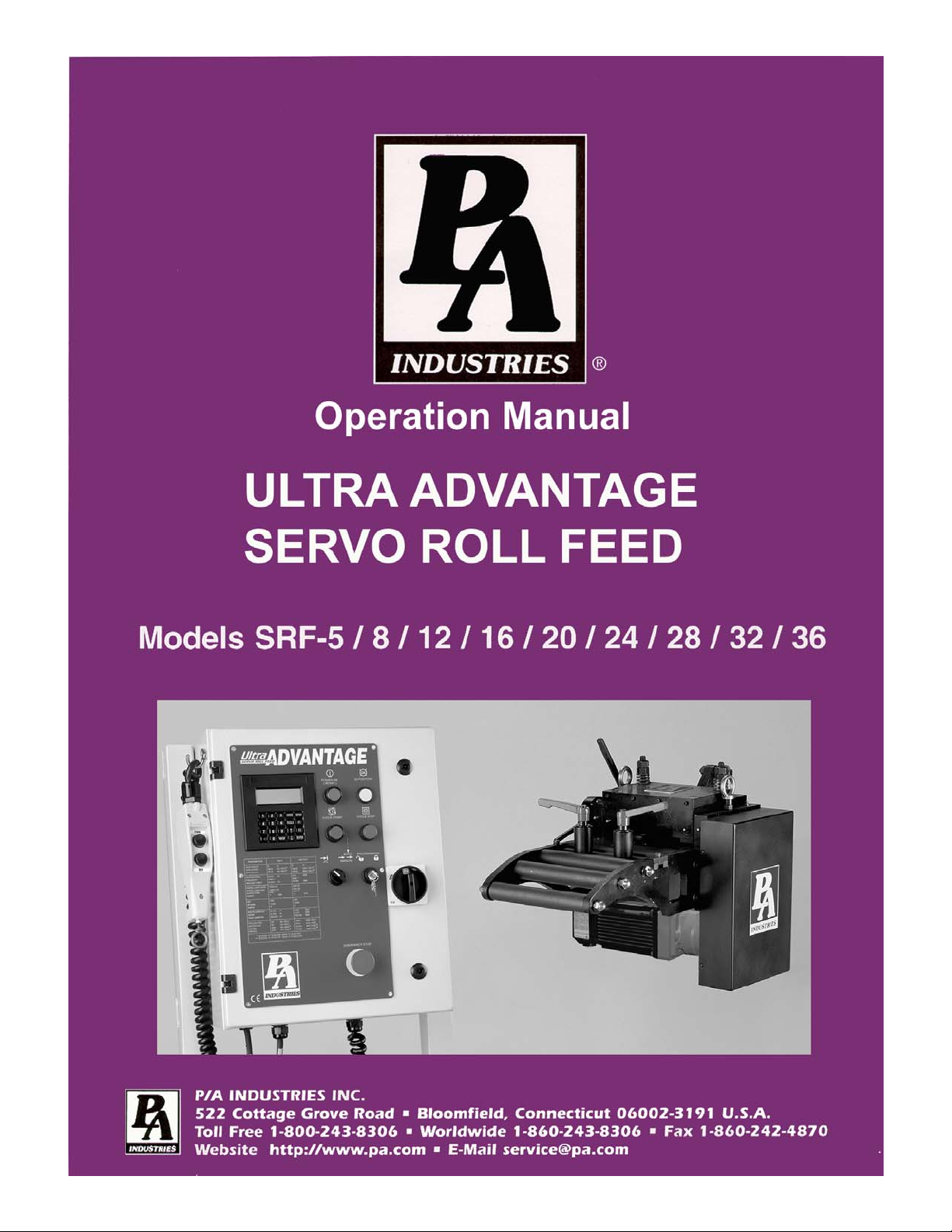
2.1 MECHANICAL ASSEMBLY
Mechanical assembly consists of:
1) Adjustment/Mounting bracket
2) Feeder
3) Servomotor
4) Mechanical pilot release actuator (optional)
5) PLS – Programmable Limit Switch (optional)
2.2 ELECTRICAL CONTROL ENCLOSURE ASSEMBLY
Electrical control enclosure consists of:
1) Control switches/buttons/relays
2) Power supply, 24 VDC/5 VDC
3) Servo drive
4) Data entry terminal
5) Cabling
6) Jog Pendant
3
ULTRA ADVANTAGE SERVO ROLL FEED 2/14/2003
ALL ULTRA ADVENTAGE SERVO ROLL FEED CONTROLS ARE CONVENIENTLY LOCATED
ON THE FRONT SIDE OF THE ELECTRICAL ENCLOSURE
CONTROL/DEVICE DESCRIPTION
Power On/Reset button Turns controller on, resets the servo drive.
In Position indicator light, white Turns on when move is complete and motor is holding position.
Cycle Start illuminated button, green Turns controller into “Auto” mode from “Manual” mode, starts cycling.
Cycle Stop button, red: Stops cycling and returns the controller into “Manual” mode.
“JTL / Manual-Auto” mode selector
switch:
Emergency Stop mushroom button, red Shuts controller off
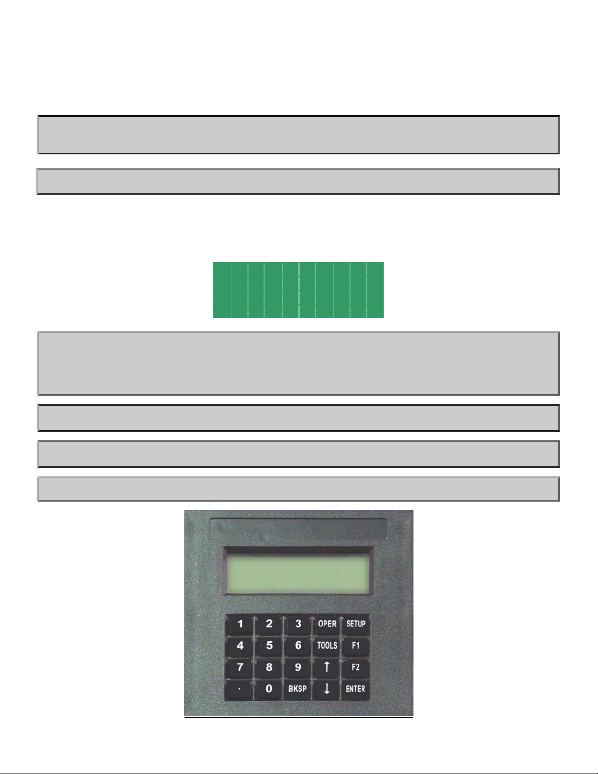
Operator terminal Displays controller’s data and enters data into controller.
“Programming Locked / Unlocked” keyswitch
Forward / Reverse remote jog pendant Pendant is attached to the enclosure through retractile cable.
Turns controller into “Manual” or “JTL” (Jog To Length) mode.
Locks access to programming.
2.3 SERVOMOTOR/DRIVE OPERATION
The introduction of servomotor technology to the press roll feed has pushed the limits of accuracy, adjustability, and
performance to levels previously unattainable.
The following example is based on the Ultra Advantage Servo Roll Feed Standard, US model. The actual numbers for
Heavy Duty or metric models are different.
Each revolution of the servomotor produces 8000 encoder pulses. Every 10.24 revolutions of the servo motor shaft
produce 1 revolution of the feed rollers. The circumference of the lower roll is approximately 11.138 inches.
When a new feed pitch is entered into the system, the built in computer calculates the correct number of electronic
“pulses” it must receive from the motor mounted encoder in order to rotate the feed rolls the correct distance.
4

ULTRA ADVANTAGE SERVO ROLL FEED 2/14/2003
Example: If a feed pitch/length of 11.138 inches is entered into the feeder, this will result in exactly one revolution of the
feed rolls. The motor will accelerate and turn 10.24 turns. This will produce (10.24 x 8000 = 81,920) pulses of the
encoder. The feeder will decelerate and stop, when 81,920 pulses are detected. The feeder is now in position. The result
is an accurately positioned strip exactly 11.138 inches from its starting point. This entire process happens in milliseconds.
2.4 TOOL STORAGE OPERATION
The tool storage feature allows for storing of parameters that are different from tool to tool. It takes just a few seconds to
activate feeding parameters associated with a certain tool number. Maximum 200 tools can be stored. Tools are organized
by Tool number, which is user definable and can contain up to 7 digits.
Each tool consists of the following parameters:
-Length;
- Batch Count;
- Speed;
- Dwell;
- Accel;
- Decel;
- Feed Cam “On”;
- Feed Cam “Off”;
- Reset Cam “On”;
- Reset Cam “Off”;
- Pilot Release Cam “On”;
- Pilot Release Cam “Off”;
- Aux1. Cam “On”;
- Aux1. Cam “Off”;
- Aux2. Cam “On”;
- Aux2. Cam “Off”;
- Aux3. Cam “On”;
- Aux3. Cam “Off”;
NOTE: Cam settings are available only with PLS version of software.
Consider the tool storage as a part of the servo drive’s NVRAM memory that is dedicated to storing information of all the
existing tools. In order to run a tool, it must be activated. Tool activation is an internal drive procedure of making a copy
of the tool, and placing it in a different memory location. This copy, not the tool in the tool storage, is used to perform
material feeding. “Tool #NNN is active” means only that the feed running parameters are copied from this tool.
A tool in the tool storage area and its copy, are edited independently, with the difference, that only two of the copy’s
parameters are accessible – Length and Batch Count. These are accessible from the Operator screen. In order to edit the
rest of the parameters of the tool, the tool in tool storage must be edited, and then, reactivated.
NOTE: Deleting an active tool from the tool storage causes deletion of its copy as well.
NOTE: An active tool remains active after power recycling.
2.5 PLS OPERATION (OPTIONAL)
The PLS, Programmable Limit Switch consists of an intelligent encoder and the cable that connects the encoder to the
servo drive. The encoder is mounted on the press and its shaft is coupled or belted to the crankshaft with a one to one
(1:1) ratio. On every power-up, the encoder turns into the intelligent mode (for approximately 10 msec) to read its actual
position and store it in the servo drive.
5

ULTRA ADVANTAGE SERVO ROLL FEED 2/14/2003
The encoder then turns into the incremental mode, sending the count signals to the servo drive proportionally to the
angle of the move (1024 counts per revolution). The servo drive software, having the start point position of the encoder
shaft, constantly calculates (updates) its current position. The position of the press crankshaft is determined through the
offset parameter, which is the position of the encoder shaft when the press is in its 0 degree position (TDC).
Thus, at every point of the stroke, the servo drive knows where the crankshaft is. The servo drive controls six cams
simultaneously, turning them on and off accordingly to the cam settings.
Since the PLS encoder is connected directly to the servo drive, there is no need to wire connections for the Feed Cam and
the Reset Cam outputs. These outputs are software type outputs.
The rest of the cam outputs are hardware type and require wiring of output relays to the desired mechanisms, such as a
pilot release solenoid, parts blow-off, tool lubricator, etc. The cam settings (On/Off angles) are set through the operator
terminal. They are part of the tool settings.
NOTE: All PLS outputs are active as soon as SRF power is turned on.
2.6 STRIP ENCODER-OPERATION (OPTIONAL)
The Strip Encoder assembly consists of:
a. 300mm diameter knurled measuring wheel
b. 10,000 pulses per revolution encoder
c. Air valve with manual actuator
d. Air cylinder slide
e. Magnetic sensor
The encoder measuring wheel is coupled to the encoder and both are mounted on the slide. The slide can be moved up and
down by applying air pressure (80-100 PSI) to the air cylinder. The magnetic sensor is used to indicate the up/down
position of the measuring wheel.
The encoder output results in 40,000 pulses (counts) per revolution for a final resolution of 3386 counts per inch of linear
strip movement.
While the measuring wheel is in its up position, the servo roll feed acts as if there is no strip encoder attached to it, and all
of the SETUP parameters associated with a strip
The Strip Encoder may be used to control or to check the position of the material strip.
The P/A Industries® servo roll feed with optional Strip Encoder comes standard with the ability to function in one of the
two modes.
encoder operation are inactive.
1. CONTROL MODE
In this mode the position control of the material motion is done through Strip Encoder feedback. The velocity control is
based on data coming from both, Strip Encoder and Motor Mounted Encoder.
This mode provides relatively slower speed performance, due to the increase in computation of the velocity control
algorithm.
2. CHECK MODE
In this mode the full control of the material motion (Acceleration, Deceleration, Speed and positioning) is done through
the Motor Mounted Encoder. When a move is complete, the Strip Encoder positioning control checks if the material is
within the Length Check tolerance, if it is not, "Position Error" is displayed, and Auto mode is turned off.
6
ULTRA ADVANTAGE SERVO ROLL FEED 2/14/2003
3 PROGRAMMING THE ULTRA ADVANTAGE SERVO ROLL FEED SYSTEM OVERVIEW
NOTE: Before attempting any programming, make sure that the “PROGRAMMING LOCKED / UNLOCKED”
key switch is in the “Unlocked” position.
NOTE: After power shutdown, WAIT for 10 seconds before powering up the Feed.
Turn on the main power disconnect switch. This applies power to the control power supply. Press the green Power On
push-button. The button will illuminate and the OPERATOR terminal display will be visible.
Wait for the IN POSITION light to illuminate.
Press any key to begin.
P /A I n du s tr i es
R ea l ly Co o l F eed
V er s io n 1 . 00 std
H i t an y k e y t o c o nt .
NOTE: The OPERATOR terminal has three mode keys, they are:
● “OPER”
● “TOOLS”
● “SETUP”
NOTE: ▓ The flashing cursor is waiting for the value to be entered.
NOTE: < The pointer prompts to press the “ENTER” key.
NOTE: To confirm any value, press “ENTER”.
7

ULTRA ADVANTAGE SERVO ROLL FEED 2/14/2003
3.1 “OPER” KEY
“OPER” key controls appearance of two screens: STATUS screen and OPERATOR screen.
STATUS screen shows:
T o o l #1 P os : 18 2
Ma n u al Mo d e
3 0 / Co n t .R u n
P re s s a M o de Ke y
• Active tool number. In case there is no active tool “No Tool!” message is displayed instead
• Current press position in degrees. Available only on PLS model
• Current mode of the feed
• Batch count, current and commanded
NOTE: When the feed is turned into Auto mode it displays current press speed (in strokes per minute) instead of
current press position.
T o o l #1 S pd : 38 4
A u t o M od e
3 0 / Co n t .R u n
P re s s a M o de Ke y
OPERATOR screen shows and allows editing the following parameters:
L e n g th 1 . 00 0
C o u n t C o nt . Ru n
L e n g th Ad j u st m en t <
P r e ss OP E R t o e x it
• Length
• Batch count command
• Length micro adjustment
Every time the “OPER” key is pressed it toggles between the STATUS screen and the OPERATOR screen.
3.2 “TOOLS” KEY
“TOOLS” key controls appearance of TOOL STORAGE screens. Press the “TOOLS” key to open the first screen.
This allows the Operator to chose a Tool Storage operation: “Edit Tool”, “Activate Tool”, or “Create New Tool”.
E d i t T o ol
A c t i va t e T o ol <
C r e a te Ne w
P r e s s T OO L S t o e x it
8

ULTRA ADVANTAGE SERVO ROLL FEED 2/14/2003
Position the pointer on desired line, using “↑” and “↓” keys , and press the “ENTER” key.
Enter in the tool number or select it from the tool list using “↑” and “↓” keys and press the “ENTER” key again.
E d i t T o ol # 1
A r r o w k ey s to sc r ol l
P r e s s T OO L S t o e x it
A c t i va t e
T oo l # 1
A r r o w k ey s to sc r ol l
P r e s s T OO L S t o e x it
C r e a te To o l #
P r e s s T OO L S t o e x it
NOTE: Tool number can contain up to seven digits.
If “Activate Tool” operation is chosen, then the desired tool will be activated and message will be displayed for a few
seconds:
T oo l A ct i v at e d
Display will show STATUS screen.
T o o l #1 S pd : 38 4
A u t o M od e
3 0 / Co n t .R u n
P re s s a M o de Ke y
If “Activate Tool” or “Edit Tool” operation is chosen and the entered tool number doesn’t exist, the following message
will be displayed:
T o o l d o es n ‘t e xi s t!
The display will show the previous screen.
9

ULTRA ADVANTAGE SERVO ROLL FEED 2/14/2003
E d i t To o l#
A r r o w k e ys t o s cr o ll
P r e s s T O OL S to ex i t
Or
A c t i v at e
T oo l #
A r r o w k e ys t o s cr o ll
P r e s s T O OL S to ex i t
If “Edit Tool” or “Create New Tool” operation is chosen, then the next three (nine - with PLS option) screens will allow
editing of the tool parameters. Position the cursor on desired line, using “↑” and “↓” keys , enter in the desired value, and
press the “ENTER” key. Press “TOOLS” to open the next screen or “BKSP” – the previous.
T o o l # 1
L e n g t h 6 0. 0 00
C o u n t Co n t. R un
P r e s s T O OL S fo r n e xt
Length is a distance in inches (or millimeters) of the “Feed Length”. It is a numeric entry with a range of 0 to the
Maximum Length.
Count is the number of feed indexes that should be performed. It is a numeric entry with a range of 0 to 9999999.
Entering “0” will result in a continuous run.
T o o l # 1
S p e e d 72
D w e l l 0
T O O L S -n e x t B K S P- P re v
Speed is the maximum velocity of the material in in/sec (or mm/sec). It is a numeric entry with a range of 0 to 72 in/sec
(1828 mm/sec) for Standard model and 0 to 41 in/sec (1041 mm/sec) for Heavy Duty models.
Dwell controls the “On” duration of the “Permit Press” output while the control is in Single Stroke mode. The next feed
length will not be started until Dwell time is expired. It is a numeric entry with a range of 0 to 100000 msec.
T o o l # 1
A c c e l 40 0 .0
D e c e l 40 0 .0
T O O L S -n e x t B K S P- P re v
Accel is the rate of acceleration in in/sec2 (or mm/sec2). It is a numeric entry with a range of 0-to 1000 in/sec2 (25400
mm/sec
Decel is the rate of deceleration in in/sec
mm/sec
2
). Normally set to 400 in/sec2 (10160 mm/sec2).
2
2
). Normally set to 400-in/ sec2 (10160 mm/sec2). Enter “0” to duplicate Accel rate.
(or mm/sec2). It is a numeric entry with a range of 0-to 1000 in/sec2 (25400
NOTE: The following six screens are part of the optional PLS package and displayed only if the corresponding
software is loaded.
10

ULTRA ADVANTAGE SERVO ROLL FEED 2/14/2003
NOTE: Each of the following six PLS screens (Feed Cam, Reset Cam, Pilot Release, Auxiliary 1,2,3) has a press
current position shown at the top right corner.
T o o l # 1 P o s: 3 54
F e e d C am On 2 60
F e e d C am Of f 9 0
T O O L S -n e x t B K S P- P re v
FeedCam On indicates the position of the press when the feed cam switch turns on and the feed starts feeding the
material.
FeedCam Off indicates the position of the press where the feeding must be completed. Otherwise, the servo drive will
generate Synch Fault Signal, display the corresponding message in the screen, and stop feeding.
T o o l # 1 P o s: 3 54
R e s e t Ca m O n 1 80
R e s e t Ca m O f f 2 00
T O O L S -n e x t B K S P- P re v
ResetCam On indicates the position of the press when the reset cam switch turns on.
ResetCam Off indicates the position of the press when the reset cam switch turns off.
T o o l # 1 P o s: 3 54
P i l o t Re l O n 1 25
P i l o t Re l O f f 2 40
T O O L S -n e x t B K S P- P re v
Pilot Release On indicates the position of the press when the pilot release cam switch turns on to open the rolls.
Pilot Release Off indicates the position of the press when the pilot release cam switch turns off to close the rolls.
T o o l # 1 P o s: 3 54
A u x 1 On 0
A u X 1 Of f 1 20
T O O L S -n e x t B K S P- P re v
T o o l # 1 P o s: 3 54
A u x 2 On 1 2 0
A u X 2 Of f 2 40
T O O L S -n e x t B K S P- P re v
T o o l # 1 P o s: 3 54
A u x 3 On 2 4 0
A u X 3 Of f 0
T O O L S -n e x t B K S P- P re v
Auxiliary 1 (2, 3) On indicates the position of the press when the auxiliary cam switch turns on.
11
 Loading...