


PA Industries SRF-5, SRF-8, SRF-12, SRF-16, SRF-20 User Manual
...
|
ULTRA ADVANTAGE SERVO ROLL FEED |
2/09/2002 |
|
|
|
TABLE OF CONTENTS |
|
|
|
|
|
|
|
|
DESCRIPTION |
|
PAGE |
||
1 INTRODUCTION.......................................................................................................................................... |
|
3 |
||
2 THEORY OF OPERATION ........................................................................................................................ |
|
3 |
||
2.1 |
MECHANICAL ASSEMBLY.............................................................................................................. |
|
3 |
|
2.2 ELECTRICAL CONTROL ENCLOSURE ASSEMBLY ......................................................................... |
|
3 |
||
2.3 |
SERVOMOTOR/DRIVE OPERATION............................................................................................ |
|
4 |
|
2 PROGRAMMING THE ULTRA ADVANTAGE SERVO ROLL FEED SYSTEM - OVERVIEW ....... 5 |
||||
2.1 |
“OPER” KEY......................................................................................................................................... |
|
6 |
|
2.2 |
“SETUP” KEY....................................................................................................................................... |
|
7 |
|
4 HOW TO …................................................................................................................................................... |
|
9 |
||
4.1 |
HOW TO EDIT “OPERATOR” PARAMETERS .......................................................................... |
|
9 |
|
4.2 |
HOW TO EDIT “SETUP” PARAMETERS ................................................................................... |
|
9 |
|
4.3 |
HOW TO MICRO ADJUST LENGTH USING LENGTH ADJUSTMENT................................. |
10 |
||
5 OPERATING THE ULTRA ADVANTAGE SERVO FEED................................................................... |
|
10 |
||
5.1 |
PROGRAMMING.............................................................................................................................. |
|
10 |
|
5.2 |
PRIORITY MODE............................................................................................................................. |
|
10 |
|
5.3 |
“JTL” (JOG TO LENGTH) MODE ................................................................................................. |
|
10 |
|
5.4 |
“AUTO / MANUAL” MODE.............................................................................................................. |
|
11 |
|
5.5 |
TROUBLESHOOTING GUIDE....................................................................................................... |
|
13 |
|
5.6 |
ERROR CODES ............................................................................................................................... |
|
14 |
|
WARNING ...................................................................................................................................................... |
|
16 |
||
SAFETY PROGRAM .................................................................................................................................... |
|
16 |
||
WARRANTY................................................................................................................................................... |
|
16 |
||
2

ULTRA ADVANTAGE SERVO ROLL FEED |
2/09/2002 |
RECEIVING INSPECTION
BEFORE REMOVING UNIT FROM ITS PACKAGING, CHECK FOR VISUAL DAMAGE, ESPECIALLY IF CRATE, SKID, OR CARTON HAS BEEN DAMAGED IN TRANSIT. ANY DAMAGE CAUSED IN SHIPMENT SHOULD BE IMMEDIATELY REPORTED TO THE CARRIER. IF UNIT APPEARS IN SATISFACTORY CONDITION, REMOVE ALL PACKING AND WIPE RUST PREVENTIVE FROM ROLLERS WITH MILD SOLVENT.
1 INTRODUCTION
IMPORTANT
Before turning the system on for the first time, verify that installation has been completed according to the Installation manual and the main input voltage is 220 VAC, single phase.
The P/A Industries Ultra Advantage Servo Roll Feed is a state of the art AC Servo feed, which simplifies Operator adjustments to feed parameters. These Operator adjustments are entered into the control memory through the keypad. With the use of positional limit switches, the press signals the feeder when to begin moving the strip, when the feed pitch must be completed, when the press has completed its down stroke, and with optional pneumatic pilot release, when to open the rolls for piloting.
The mechanical simplicity, accuracy, and ease of use of the Ultra Advantage Servo Roll Feed will help to improve your quality and production for years to come.
2 THEORY OF OPERATION
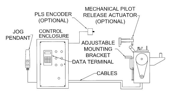
2.1 MECHANICAL ASSEMBLY
Mechanical assembly consists of:
1)Adjustment/Mounting bracket
2)Feeder
3)Servomotor
4)Mechanical pilot release actuator (optional)
5)PLS – Programmable Limit Switch (not available with SFI models)
2.2ELECTRICAL CONTROL ENCLOSURE ASSEMBLY
Electrical control enclosure consists of:
1)Control switches/buttons/relays
2)Power supply, 24 VDC/5 VDC
3)Servo drive
4)Data entry terminal
5)Cabling
6)Jog Pendant
3
ULTRA ADVANTAGE SERVO ROLL FEED |
2/09/2002 |
ALL ULTRA ADVENTAGE SERVO ROLL FEED CONTROLS ARE CONVENIENTLY LOCATED ON THE FRONT SIDE OF THE ELECTRICAL ENCLOSURE
CONTROL/DEVICE |
DESCRIPTION |
|
|
Power On/Reset button |
Turns controller on, resets the servo drive. |
|
|
In Position indicator light, white |
Turns on when move is complete and motor is holding position. |
|
|
Cycle Start illuminated button, green |
Turns controller into “Auto” mode from “Manual” mode, starts cycling. |
|
|
Cycle Stop button, red: |
Stops cycling and returns the controller into “Manual” mode. |
|
|
“JTL / Manual-Auto” mode selector |
Turns controller into “Manual” or “JTL” (Jog To Length) mode. |
switch: |
|
|
|
Emergency Stop mushroom button, red |
Shuts controller off |
|
|
Operator terminal |
Displays controller’s data and enters data into controller. |
|
|
“Programming Locked / Unlocked” key- |
Locks access to programming. |
switch |
|
|
|
Forward / Reverse remote jog pendant |
Pendant is attached to the enclosure through retractile cable. |
|
|
2.3 SERVOMOTOR/DRIVE OPERATION
The introduction of servomotor technology to the press roll feed has pushed the limits of accuracy, adjustability, and performance to levels previously unattainable.
The following example is based on the Ultra Advantage Servo Roll Feed Standard, US model. The actual numbers for Heavy Duty or metric models are different.
Each revolution of the servomotor produces 8000 encoder pulses. Every 10.24 revolutions of the servo motor shaft produce 1 revolution of the feed rollers. The circumference of the lower roll is approximately 11.138 inches.
When a new feed pitch is entered into the system, the built in computer calculates the correct number of electronic “pulses” it must receive from the motor mounted encoder in order to rotate the feed rolls the correct distance.
4

ULTRA ADVANTAGE SERVO ROLL FEED |
2/09/2002 |
Example: If a feed pitch/length of 11.138 inches is entered into the feeder, this will result in exactly one revolution of the feed rolls. The motor will accelerate and turn 10.24 turns. This will produce (10.24 x 8000 = 81,920) pulses of the encoder. The feeder will decelerate and stop, when 81,920 pulses are detected. The feeder is now in position. The result is an accurately positioned strip exactly 11.138 inches from its starting point. This entire process happens in milliseconds.
2 PROGRAMMING THE ULTRA ADVANTAGE SERVO ROLL FEED SYSTEM - OVERVIEW
NOTE: Before attempting any programming, make sure that the “PROGRAMMING LOCKED / UNLOCKED” key switch is in the “Unlocked” position.
NOTE: After power shutdown, WAIT for 10 seconds before powering up the Feed.
Turn on the main power disconnect switch. This applies power to the control power supply. Press the green Power On push-button. The button will illuminate and the OPERATOR terminal display will be visible.
Wait for the IN POSITION light to illuminate. Press any key to begin.


 P/A
P/A Industries


 Really
 Cool
Cool Feed
Feed


 Version
 1.16
1.16 SFI
SFI

Hit any
any key
key to
to cont .
NOTE: The OPERATOR terminal has three mode keys, they are:
●“OPER”
●“TOOLS” ” – disabled on SFI model.
●“SETUP
NOTE: ▓ The flashing cursor is waiting for the value to be entered.
NOTE: < The pointer prompts to press the “ENTER” key.
NOTE: To confirm any value, press “ENTER”.
5
 Loading...