


Form 1145 |
Mini Installation Form and Operation Manual |
02/02/2006 |

Form 1145 |
Mini Installation Form and Operation Manual |
02/02/2006 |
RECEIVING INSPECTION
Before removing unit from its packaging, check for visual damage, especially if crate, skid, or carton has been damaged in transit. Any damage caused by shipping should be immediately reported to the carrier. If unit appears in satisfactory condition, remove all packing and wipe rust preventive from rollers with mild solvent.
|
TABLE OF CONTENTS |
|
DESCRIPTION |
PAGE |
|
RECEIVING INSPECTION........................................................................................................................... |
2 |
|
1 |
INTRODUCTION............................................................................................................................. |
3 |
2 |
HOW A SERVO FEED OPERATES.............................................................................................. |
3 |
3 |
INSTALLING YOUR “MINI” SERVO FEED.............................................................................. |
4 |
3.1 |
MECHANICAL INSTALLATION .................................................................................................... |
4 |
3.2 |
ELECTRICAL INSTALLATION ...................................................................................................... |
4 |
3.3 |
ELECTRICAL CONNECTIONS ....................................................................................................... |
4 |
4 |
PROGRAMMING THE “MINI” .................................................................................................... |
6 |
4.1 |
ENTER FEED LENGTH.................................................................................................................... |
7 |
4.2 |
ENTER FEED SPEED........................................................................................................................ |
8 |
4.3 |
ENTER FEED ACCEL....................................................................................................................... |
8 |
4.4 |
SET-UP PARAMETERS.................................................................................................................... |
9 |
5 |
OPERATING THE FEED ............................................................................................................. |
10 |
5.1 |
LOADING THE FEED..................................................................................................................... |
10 |
5.2 |
AUTO/MANUAL MODE ................................................................................................................ |
10 |
5.3 |
FEED SIGNAL ................................................................................................................................. |
12 |
5.4 |
CONTROL FAULT CONDITIONS................................................. |
Error! Bookmark not defined. |
5.5 |
SERVO DRIVE FAULT TABLE..................................................................................................... |
12 |
5.6 |
SPEED PERFORMANCE GRAPH ................................................................................................. |
19 |
6 |
PNEUMATIC PILOT RELEASE................................................................................................. |
19 |
6.1 |
PILOT RELEASE PARTS LIST AND DIAGRAM ....................................................................... |
19 |
7 |
MAINTENANCE ............................................................................................................................ |
20 |
8 |
ROLL FEED PARTS LIST & DIAGRAM .................................................................................. |
21 |
|
WARRANTY................................................................................................................................... |
23 |
2
Form 1145 |
Mini Installation Form and Operation Manual |
02/02/2006 |
1. INTRODUCTION
The P/A Industries Mini Servo Roll Feed is a state of the art AC Servo feed, which eases operator adjustments to feed pitch, speed, and acceleration. These operator adjustments are entered into the control memory by keypad input. With the use of a positional limit switch, the press signals the feeder when to begin moving the strip. The operating speed of the press should be set to provide adequate time for the index to be completed while the die is open.
The mechanical simplicity, accuracy, and ease of use of the Mini Servo Roll Feed should help to improve your quality and production for years to come.
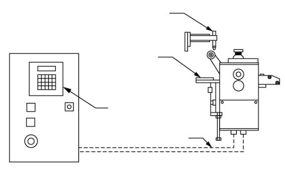
2. HOW A SERVO FEED OPERATES
The Mini Servo Roll Feed consists of:
1)Mechanical assembly
2)Servomotor
3)Servo Control
MECHANICAL PILOT
RELEASE ACTUATOR
CONTROL
ENCLOSURE
ADJUSTABLE
MOUNTING
BRACKET
DATA
TERMINAL
CABLES
Figure 1
The servo control acts as the central processor for the Mini Servo Roll Feed. Feed parameters entered into the servo control are processed to position the servomotor. Calibration of the motor encoder to the feed roll circumference allows accurate positioning of the feed roll. Each revolution of the servomotor produces 8000 encoder pulses. Every 2.857 revolutions of the servo motor shaft produce 1 revolution of the feed rollers. The circumference of the lower roll is approximately 5.566 inches.
When a new feed pitch is entered into the system, the built-in computer calculates the correct number of electronic “pulses” it must receive from the motor mounted encoder in order to rotate the feed rolls the correct distance.
Example: If a feed pitch/length of 5.566 inches is entered into the feeder, this will result in exactly one revolution of the feed rolls. The motor will accelerate and turn 2.857 turns. This will produce (2.857 x 8000 = 22,856) pulses of the encoder. The feeder will decelerate and stop when 22,856 pulses are detected. The feeder is now on position. The
3

Form 1145 |
Mini Installation Form and Operation Manual |
02/02/2006 |
end result is an accurately positioned strip exactly 5.566 inches from its starting point. This entire process happens in milliseconds.
3.INSTALLING YOUR “MINI” SERVO FEED
3.1MECHANICAL INSTALLATION
The Mini Servo Roll Feed is supplied with an adjustable mounting bracket. The feed should be securely mounted to the press frame. (A transition bracket is sometimes required in certain applications.) The feed should be centered, square, and perpendicular to the pass line of the press. It should be mounted at a height that will accommodate the appropriate die sets. The feed has a pass line height adjustment of ±1.2 inches (Note: The centerline of the Feeder is NOT the centerline of the rolls.) Refer to Figure 2 on Page 4 for dimensioning.
The feeder may be used to push or pull strip stock through the die.
If pilot locating pins are used in your die sets, the optional mechanical roll release bracket should be attached to the press ram. It must be mounted in such a way as to provide roll release at the proper time and be adjustable for different die sets.
If the optional electro-pneumatic piloting is used, another cam switch will be necessary for controlling feed roll opening and closing.
3.2ELECTRICAL INSTALLATION
The Mini Servo Roll Feed has been designed to make electrical connections quickly and easily. Simply connect the power plug to a "clean" 115 VAC, single phase, 10-Ampere source (15-Ampere for SRF-320 model). Avoid having other equipment share the same circuit as the feeder. The inputs and outputs to your press control (i.e. Emergency Stop, Feed Cam Contact, Pilot Release Cam Contact) must also be connected for proper operation. The motor connects by factory installed "Amphenol" (Military Specifications) Quick connectors.
3.3ELECTRICAL CONNECTIONS
For more detailed wiring information refer to Electrical Schematic A-17647-11.
NOTE:
All connections should be made in accordance with National Electrical Code (NEC) requirements and must comply with all local ordinances.
NOTE:
A word about electrical “noise”. Most pressroom environments contain considerable electrical noise. It is emitted from electro-mechanical press relays, contacts, and solenoids. While the Mini Servo Roll Feed has been designed to minimize “self generated” electrical noise, it is difficult to provide protection for all applications. If erratic system behavior is experienced, then the source of the “noise” must be suppressed with either a resistive/capacitive type of suppressor on AC coils, or “Avalanche” type diodes on DC coils.
NOTE:
The Mini Servo Roll Feed is fully protected by line circuit breakers. If it becomes necessary to replace the fuses, use only exact equivalent fuse types to prevent serious damage to the system.
NOTE:
The electrical control enclosure is supplied with a stand-support, which may be placed in any convenient location. The enclosure may also be mounted in any fixed location as long as the cabling is adequate to reach the feed. It is not recommended that the electrical enclosure be mounted directly to the press. The vibrations caused by the punch press can result in damage to the control system.
4

Form 1145 |
Mini Installation Form and Operation Manual |
02/02/2006 |
PASS LINE
|
|
|
|
|
|
|
|
K - PASS LINE |
|||||||
|
|
|
|
|
|
|
|
ADJUSTMENT |
|||||||
|
|
|
|
|
|
|
|
|
|
|
|
|
|
||
|
|
|
|
|
|
|
|
J |
|
|
|
|
|
|
|
BOLSTER |
|
|
|
|
|
|
|
|
|
|
|
|
|
|
|
|
|
|
|
|
|
|
|
|
|
|
|
|
|
||
|
|
|
|
|
|
|
|
|
|
|
|
|
|
|
|
|
|
|
|
|
|
|
C |
|
|
|
|
|
|
|
|
|
|
|
|
|
|
|
|
|
|
|
|
|
|
|
|
|
|
|
|
A |
|
|
|
|
|
|
|
|
|||
|
B |
|
|
|
|
PASS LINE |
F |
|
|
||||||
|
|
|
|
|
|
|
|
|
|||||||
|
|
|
|
|
|
||||||||||
|
|
|
|
|
|
|
|
|
|
|
|||||
|
|
|
|
|
|
|
|
||||||||
|
|
|
|
|
|
|
|
|
|
|
|
|
|
|
|
|
|
|
|
|
|
|
|
|
|
|
|
|
|
|
H |
0.551’’ |
|
|
|
|
|
|
|
|
|
|
|
|
|
|
|
|
|
|
|
|
|
|
|
|
|
|
|
|
|
||
( 14MM) |
|
|
|
|
|
|
|
|
|
|
|
|
|
|
|
|
|
|
|
|
|
|
|
|
E |
|
|
|
|
||
THRU |
|
|
|
|
|
|
|
|
|
|
|
|
|
||
|
|
|
|
|
|
|
|
G |
|||||||
MOUNTING |
|
|
|
|
|
|
|
|
|
|
|
|
|
||
|
D |
|
|
|
|
|
|
|
|
|
|
||||
HOLES |
|
|
|
|
|
||||||||||
|
|||||||||||||||
|
|
|
|
|
|
|
|
|
|
|
|
|
|
|
|
Figure 2
|
|
MOUNTING DIMENSIONS |
|
|
|
||
|
SRF-105M |
SRF220M |
SRF-320M |
|
|
||
DIMENSION |
INCHES |
MILLIMETERS |
INCHES |
MILLIMETERS |
INCHES |
MILLIMETERS |
|
A |
4.63 |
117.50 |
6.89 |
175.00 |
8.86 |
225.00 |
|
B |
1.77 |
45.00 |
1.77 |
45.00 |
1.77 |
45.00 |
|
C |
9.25 |
235.00 |
13.78 |
350.00 |
17.72 |
450.00 |
|
D |
1.97 |
50.00 |
3.94 |
100.00 |
3.94 |
100.00 |
|
E |
3.94 |
100.00 |
7.87 |
200.00 |
7.87 |
200.00 |
|
F |
1.58 |
40.00 |
1.58 |
40.00 |
1.58 |
40.00 |
|
G |
1.58 |
40.00 |
1.58 |
40.00 |
1.57 |
40.00 |
|
H |
4.72 |
120.00 |
4.72 |
120.00 |
4.72 |
120.00 |
|
J |
0.79 |
20.00 |
0.79 |
20.00 |
0.79 |
20.00 |
|
K - PASS LINE |
MAX 4.37 |
MAX 111 |
MAX 4.37 |
MAX 111 |
MAX 4.37 |
MAX 111 |
|
ADJUSTMENT |
MIN 2.O1 |
MIN 51 |
MIN 2.O1 |
MIN 51 |
MIN 2.O1 |
MIN 51 |
|
5

Form 1145 |
Mini Installation Form and Operation Manual |
02/02/2006 |
4. PROGRAMMING THE “MINI”
IMPORTANT!
Before turning the system on for the first time, verify that the main input voltage is correct (115 VAC single phase) and inspect all connections for tightness, shorts, etc.
Plug the 115 VAC plug into a clean 10 Amp supply (15 Amp for SRF-320 model. Press the amber ‘POWER ON’ push button. The button will illuminate and the data input display will be visible. If pressing the ‘POWER ON’ push button has no effect, then check the ‘TWIST-TO-UNLOCK’ Emergency Stop button for the ‘UP’ or ‘RELEASED’ position.
Start up screen is displayed for about 5 seconds.
 P/A
P/A Industries
 Inc
Inc


 MINI
MINI


 Servo
Servo Roll
Roll Feed
Feed


V2.1
 Copyright
 2004
2004
Provided no fault is present, the following screens will appear sequentially:


 Checking


 servo
servo
 drive
drive


 No
No faults
 found !


 Communications


 with
with servo
servo drive
drive


 established


In case of a fault condition present in the servo drive, the following flashing screen will display all present faults by their numbers. Fault numbers and their descriptions are listed in the fault table on page 13 of this manual.


 Fault
Fault code:
code: 30
30


See fault
fault code
code table
table
Any fault problem must be solved before further operating.
Normally, there are no faults and the keypad reads values of Length, Speed and Accel, stored in the servo drive.


 Getting
 Length


6

Form 1145 |
|
|
|
|
|
|
|
Mini Installation Form and Operation Manual |
02/02/2006 |
||||||||||||||||||||||||||||||||
|
|
|
|
|
|
|
|
|
|
|
|
|
|
|
|
|
|
|
|
|
|
|
|
|
|
|
|
|
|
|
|
|
|
|
|
|
|
|
|
|
|
|
|
|
|
|
|
|
|
|
|
|
|
|
|
|
|
|
|
|
|
|
|
|
|
|
|
|
|
|
|
|
|
|
|
|
|
|
|
|
|
|
|


 Getting
 Speed
Speed


 Getting
 Accel
Accel


At this point a servo feed ready for normal operation.
Units of measure are displayed in inches or meters/millimeters, depending on the value of the scale parameter. Standard Scale values are: 4106.7 counts/inch and 161.7 counts/mm.
1 |
Length:2 |
|
|
. |
54 |
|
|
in |
|||
2 |
Speed: |
|
100 |
|
|
in/s |
|||||
3 |
|
Accel:400 |
|
|
|
|
in/s |
|
^2 |
||
E |
nter |
|
choice: |
|
|
|
|
||||
|
|
|
|
|
|
||||||
1 |
|
Length:25 |
|
|
. |
4 |
|
|
mm |
||
2 |
Speed: |
|
2 |
. |
5 |
|
|
|
m/s |
||
3 |
Accel:10 |
|
|
|
|
|
m/s |
^2 |
|||
Enter choice:


To Change:
>Length press ‘1’ then ‘ENTER’
>Speed press ‘2’ then ‘ENTER’
>Accel press ‘3’ then ‘ENTER’
4.1 ENTER FEED LENGTH
Enter in ‘1’ and press ‘ENTER’.
|
1 |
|
|
|
|
|
|
Length:2 |
|
|
|
. |
|
54 |
|
|
|
|
in |
|||
|
2 |
|
|
|
|
|
Speed: |
100 |
|
|
|
|
|
|
|
|
in/s |
|
||||
|
3 |
|
|
|
|
|
|
Accel:400 |
|
|
|
|
|
|
|
|
|
|
|
in/s^2 |
|
|
Enter choice:


Enter in the new feed Length and press ‘ENTER’ or to cancel, press ‘ENTER’ (leave the Length field blank).
Length:2.54


 in
in
New Length:


|
|
|
|
|
|
|
|
|
|
|
|
|
|
|
|
|
|
|
|
|
|
|
|
|
|
|
|
|
|
|
|
|
|
|
|
|
|
|
|
|
P |
|
|
ress |
|
|
|
|
|
|
ENTER |
|
|
|
|
|
to |
|
|
|
|
exit |
|
|
|
||||||||||||||
|
|
|
|
|
|
|
|
|
|
|
|
|
|
|
|
|
|
|
|
||||||||||||||||||||
|
L |
|
|
|
ength:2 |
|
|
|
. |
|
54 |
|
|
|
|
|
|
|
|
|
|
|
|
|
|
|
in |
||||||||||||
|
N |
|
ew |
|
|
|
|
|
|
Length:3 |
|
|
|
|
. |
|
00 |
|
|
|
|
|
|
|
|
|
|
||||||||||||
|
P |
|
|
resS |
|
|
|
|
|
|
ENTER |
|
|
|
|
|
to |
|
|
|
|
exit |
|
|
|
||||||||||||||
7
 Loading...