


SRF-100
®
Installation and Operating Instructions
EDGE SERVO FEED
Models SRF-100 / 125 / 200 / 300 / 400 / 500 / 600
(for Serial Numbers 7610697 and higher)
P/A INDUSTRIES INC.
522 Cottage Grove Road • Bloomfield, Connecticut 06002-3191 U.S.A.
Toll Free 1-800-243-8306 • Worldwide 1-860-243-8306 • Fax 1-860-242-4870
Website http://www.pa.com • E-Mail service@pa.com
RECEIVING INSPECTION
Before removing unit from its packaging, check for
visual damage, especially if crate, skid, or carton has
been damaged in transit. Any damage caused by
shipping should be immediately reported to the
carrier. If unit appears in satisfactory condition,
remove all packing and wipe rust preventive from
rollers with mild solvent.
TABLE OF CONTENTS
1. INTRODUCTION
The P/A Industries Edge Servo Roll Feed is
a state of the art AC Servo feed which eases operator
adjustments to feed pitch, feeder speed, and feed
acceleration. These operator adjustments are entered
into the control memory by key pad input. With the
use of positional limit switches, the press signals the
feeder when to begin moving the strip, when the
feed pitch must be completed, when the press has
completed its down stroke, and with optional pneumatic release, when to open the rolls for piloting.
DESCRIPTION PAGE
1. INTRODUCTION ................................... 2
2. HOW AN EDGE
SERVO FEED OPERATES .................... 2
2.1 MECHANICAL ASSEMBLY .............. 2
2.2 ELECTRICAL CONTROL
ENCLOSURE ASSEMBLY ............... 2
3. INSTALLING YOUR EDGE
SERVO FEED ........................................ 3
3.1 MECHANICAL INSTALLATION ........ 3
3.2 ELECTRICAL INSTALLATION .......... 3
3.3 ELECTRICAL CONNECTIONS ........ 3
3.4 EDGE MOUNTING HOLES .............. 4
4. PROGRAMMING THE EDGE SERVO
FEED SYSTEM ...................................... 4
4.1 PROGRAM A NEW FEED
LENGTH, COUNT, SPEED .............. 6
4.2 PROGRAM A NEW BATCH
COUNT ............................................. 6
4.3 PROGRAM A NEW SPEED
FOR THE FEED ............................... 6
5. OPERATING THE FEED ....................... 7
The mechanical simplicity, accuracy, and ease of use
of the Edge Servo Roll Feed should help to improve
your quality and production for years to come.
2. HOW AN EDGE SERVO
FEED OPERATES
The Edge Servo Roll Feed consists of:
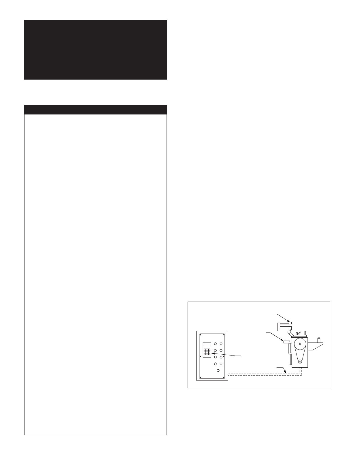
2.1 MECHANICAL ASSEMBLY
(Refer to Figure 1)
1) Adjustment/Mounting bracket
2) Feeder
3) Motor
4) Mechanical pilot release actuator
2.2 ELECTRICAL CONTROL
ENCLOSURE ASSEMBLY
(Refer to Figure 1)
1) Control switches/buttons
2) Power supply, 120 VAC (for controls)
3) Motor/Axis control module
(inside electrical enclosure)
4) Data entry terminal
5) Cabling
5.1 PRIORITY MODE ............................ 7
5.2 SET-UP MODE ................................. 7
5.3 AUTO/MANUAL MODE .................... 7
5.4 LOADING THE FEED ....................... 8
5.5 RUNNING THE FEED ....................... 8
6. TROUBLESHOOTING GUIDE ..............11
6.1 PRO-200 MOTION
CONTROL CARD ERRORS ............12
6.2 DRIVE MODULE DIAGNOSTICS ....13
7. MAINTENANCE ....................................13
8. ROLL FEED PARTS LIST
AND DIAGRAM ....................................14
WARNING .................................................... 16
SAFETY PROGRAM ....................................16
WARRANTY .................................................16
CONTROL
ENCLOSURE
Figure 1.
MECHANICAL PILOT
RELEASE ACTUATOR
ADJUSTABLE
MOUNTING
BRACKET
DATA
TERMINAL
CABLES
DRAWING 17415
The introduction of servomotor technology to the
press roll feed has pushed the limits of accuracy,
adjustability, and performance to levels previously
unattainable.
2

Each revolution of the servo motor produces 8000
encoder pulses. Every 2.909 revolutions of the
servo motor shaft produce 1 revolution of the feed
rollers. The circumference of the lower roll is
approximately 11.142 inches (on the SRF-125).
When a new feed pitch is entered into the system,
the built in computer calculates the correct
number of electronic "pulses" it must receive from
the motor mounted encoder in order to rotate the
feed rolls the correct distance.
Example: If a feed pitch/length of 11.142 inches is
entered into the feeder, this will result in exactly one
revolution of the feed rolls. The motor will accelerate and turn 2.909 turns. This will produce (2.909
x 8000 = 23,272) pulses of the encoder. The feeder
will decelerate and stop when 23,272 pulses are
detected. The feeder is now on position. The end
result is an accurately positioned strip exactly
11.142 inchs from its starting point. This entire
process happens in milliseconds.
having other equipment share the same circuit as the
feeder.) The inputs and outputs to your press control
(i.e. Emergency Stop, Feed Advance Cam Contact, Pilot
Release Cam Contact, Continue Cam Contact, End
of Strip Input) must also be connected for proper
operation. The motor connects by factory installed
"Amphenol" (Military Specifications) Quick connectors.
3.3 ELECTRICAL CONNECTIONS
For more detailed wiring information, refer to
Electrical Schematic A-17557-01 for 115 VAC and
Electrical Schematic A-17557-02 for 230 VAC.
NOTE:
All connections should be made in accordance
with National Electrical Code (NEC)
requirements and must comply with all local
ordinances.
3. INSTALLING YOUR EDGE
SERVO FEED
3.1 MECHANICAL INSTALLATION
The Edge Servo Roll Feed is supplied with an
adjustable mounting bracket. The feed should be
securely mounted to the press frame. (A transition
bracket is sometimes required in certain
applications). The feed should be centered, square,
and perpendicular to the pass line of the press.
It should be mounted at a height that will
accommodate the appropriate die sets. The feed
has a pass line height adjustment of ±1.2 inches
(Note: The centerline of the Feeder is NOT the
centerline of the rolls.) Refer to Figure 2 on
Page 4 for dimensioning.
The feeder may be used to push or pull strip stock
through the die.
If pilot locating pins are used in your die sets, the
optional mechanical roll release bracket should be
attached to the press ram. It must be mounted in
such a way as to provide roll release at the proper
time and be adjustable for different die sets.
If the optional electro-pneumatic piloting is
used, another cam switch will be necessary for
controlling feed roll opening and closing.
3.2 ELECTRICAL INSTALLATION
The Edge Servo Roll Feed has been designed to
make electrical connections quickly and easily.
Simply connect the power plug to a "clean" 120
VAC single phase 15 ampere source. (Note: Avoid
NOTE:
A word about electrical “noise”. Most pressroom
environments contain considerable electrical noise.
It is emitted from electro-mechanical press relays,
contacts, and solenoids. While The Edge Servo
Roll Feed has been designed to minimize
"self generated" electrical noise, it is difficult to
provide protection for all applications. If erratic
system behavior is experienced, then the source
of the "noise" must be suppressed with either a
resistive/capacitive type of suppressor on AC
coils, or "Avalanche" type diodes on DC coils.
NOTE:
The Edge Servo Roll Feed is fully protected
by line fuses. If it becomes necessary to replace
the fuses, use only exact equivalent fuse types to
prevent serious damage to the system.
NOTE:
The electrical control enclosure is supplied with
a stand/support which may be placed in any
convenient location. The enclosure may also be
mounted in any fixed location as long as the
cabling is adequate to reach the feed. It is not
recommended that the electrical enclosure be
mounted directly to the press. The vibrations
caused by the punch press can result In
damage to the control system.
3
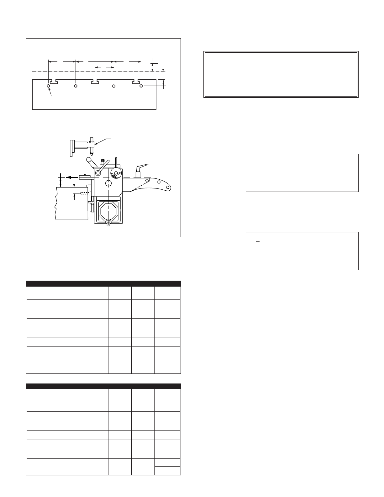
3.4 EDGE MOUNTING HOLES
4. PROGRAMMING THE EDGE
SERVO FEED SYSTEM
D
TAP X 1”(25mm) DEEP
TYPICAL MOUNTING ON GAP FRAME PRESS
E REF
PASS LINE
BOLSTER
CENTER LINE OF RAM
C
B
A REF
D
PASS LINE
BOLSTER
ADJUSTABLE
CAM BAR
DRAWING 17147-03
PASS LINE
ADJUSTMENT
E
A
IMPORTANT !
Before turning the system on for the first time,
verify that the main input voltage is correct
(120 VAC single phase) and inspect all
connections for tightness, shorts, etc.
STEP #1:
Press the amber ‘POWER ON’ push-button. The
button will illuminate and the data input display
will be visible:
P/A INDUSTRIES
☞
SERVO ROLL FEED
VERSION 1.00
HIT KEY TO CONT__
STEP #2:
Press any key on the terminal, the display will show:
Figure 2.
EDGE MOUNTING HOLES
for drawing 17147-03
INCHES
SRF-400/
DIMENSION SRF-100 SRF-125 SRF-200 SRF-300 500/600
A 1.18 1.97 1.97 1.97 1.97
B 1.97 3.15 3.94 3.94 3.94
C 3.94 6.30 7.87 7.87 7.87
D ––––5.91
TAP M14 M16 M16 M16 M16
E MIN. 2.2 2.4 2.4 2.4 2.4
PASS LINE +2 +2.4 +2.4 +2.4 +2.4
ADJUSTMENT -0.0 -0.0 -0.0 -0.0 -0.0
METRIC
SRF-400/
DIMENSION SRF-100 SRF-125 SRF-200 SRF-300 500/600
A 3050505050
B 50 80 100 100 100
C 100 160 200 200 200
D ––––150
TAP M14 M16 M16 M16 M16
E MIN. 55 60 60 60 60
PASS LINE +50 +60 +60 +60 +60
ADJUSTMENT -00.0 -00.0 -00.0 -00.0 -00.0
☞
LENGTH 00008.000
COUNT 100000
SPEED 0062/SEC
STEP #3:
The ‘POWER ON’ push-button has a ‘FAULT
RESET’ function built into the button. The feed
may now be jogged forward by pressing the ‘
FORWARD
pressing the ‘
’ button, or jogged in reverse by
JOG REVERSE’ button.
JOG
The Edge Servo Roll Feed has six viewable
screens. Only the first operator screen (shown
above) will be operator editable/programmable.
This screen displays the length, count, and speed
parameters. These parameters may only be changed
while the program is stopped (indicated by lack
of ‘
CYCLE START’ or set up light). The other
viewable screens are shown on the following page.
These five other screens will be viewable at all times,
but are "locked" out of programming via run/prog
switch located on the electrical panel inside the
electrical enclosure. The factory set parameter values
for the Edge Servo Roll Feed are printed on the
operator panel below the operator terminal.
4

These parameters are set from the factory for
average feeding applications and they seldom
require any changes. The five screens and a brief
explanation of the parameters are described below:
• LENGTH: Distance in inches (or millimeters) of
the feed length. Maximum value of 4015 inches.
CNTS/UNIT: This is the encoder scaling
parameter used to define the number encoder
counts/inch (or counts/millimeter).
• TIME BASE: Time scaling parameter for various
parameters. This is always set to ‘
entering ‘
0’.
/SEC’ by
• COUNT: The number of pieces required to run
in the batch. Maximum value of 999,999 pieces.
• SPEED: The maximum velocity of the material
in inches/second (or millimeters/second).
Maximum value of 100 inches/second.
ACCEL 000402/SEC^2
☞
• ACCEL: The rate of acceleration in
inches/second
Maximum value of 1000 inches/second
• DWELL: The time delay, which controls the ‘ON’
duration of the cut output relay. The dwell is
used when the press or shear, lacks a continue
Bottom Dead Center (BDC) switch and the cycle
can be controlled by the dwell parameter.
• DBNC: This is the debounce parameter, which
is used to ignore contact bounce on the feed
signals.
☞
• PRIORITY: This parameter selects whether the
feeder indexes before the press starts ‘
(Feed-Before-Press), or the press starts before
the feeder indexes ‘
Entering a ‘
FBP’ mode.
‘
• BACKLIGHT: This turns on the backlight in the
display which enhances the viewing.
☞
DWELL 00.00
DBNC 1 X 3.75MS
2
(or millimeters/second2).
2
.
CNTS/UNIT 2089
TIME BASE /SEC
JOG SPEED 5%
DIRECTION CCW
FBP’
PBF’ (Press-Before-Feed).
0’ selects ‘PBF’ mode or a ‘1’ selects
PRIORITY PBF
BACKLIGHT ON
• JOG SPEED: The rate of jogging speed in
percent of the ‘
between 1 - 5%.
• DIRECTION: This parameter controls the
direction of positive motor rotation. 0 = CCW,
and 1 = CW.
☞
• KP: Proportional gain parameter for the motion
control. It controls the transitions between the
starting and stopping of the rolls. A lower value
provides a smoother (slower) transition.
• KD: This parameter is not used.
• KFF: Velocity feed forward gain. This is used to
reduce following error of the system.
• AUTO OFFSET: This parameter turns the
automatic offset on. Turn this feature on by
entering ‘
☞
• INPOSN: In-position parameter is a tolerance
window around the final position. This is used to
verify the feed index accuracy is within acceptable
limits before continuing onto the next function.
• FELim: Following error limit. FELim is the
maximum allowed position error. When this limit
is exceeded for the amount of time specified by
the FETime, the control will execute an
emergency stop.
SPEED’ parameter. Normally set
KP 0.56
KD 0.00
KFF 0.50
AUTO OFFSET ON
1’.
INPOSN 000.0200
FELIM 5.000
FETIM 0.500
SYSTEM RESET
•
5
 Loading...