


ENTJ75 / ENTJ76 / ENTJ77 / ENTJ78
SERVICEGUIDE

Revision History
Please refer to the table below for the updates made on the ENTJ75 / ENTJ76 / ENTJ77 / ENTJ78 service guide.
Date Chapter Updates
Service guide files and updates are available on the ACER/CSD web. For more information, refer to http://csd.acer.com.tw
Copyright
© 2009 Packard Bell is a registered trademark of Packard Bell BV. All rights reserved. All other brands and product names are
trademarks or registered trademarks of their respective companies.
PRINTED IN TAIWAN

Contents
Chapter 1: System specifications . . . . . . . . . . . . . . . . . . . . . . . . . . . . . . . . . .1
Preface . . . . . . . . . . . . . . . . . . . . . . . . . . . . . . . . . . . . . . . . . . . . . . . . . . . . 2
Conventions . . . . . . . . . . . . . . . . . . . . . . . . . . . . . . . . . . . . . . . . . . 2
General information . . . . . . . . . . . . . . . . . . . . . . . . . . . . . . . . . . . 2
Features . . . . . . . . . . . . . . . . . . . . . . . . . . . . . . . . . . . . . . . . . . . . . . . . . . . 3
System block diagram . . . . . . . . . . . . . . . . . . . . . . . . . . . . . . . . . . . . . . . . 6
Hardware specifications and configurations . . . . . . . . . . . . . . . . . . . . . . . 7
CPU . . . . . . . . . . . . . . . . . . . . . . . . . . . . . . . . . . . . . . . . . . . . . . . . 7
Controllers . . . . . . . . . . . . . . . . . . . . . . . . . . . . . . . . . . . . . . . . . . . 7
BIOS . . . . . . . . . . . . . . . . . . . . . . . . . . . . . . . . . . . . . . . . . . . . . . . 7
Memory . . . . . . . . . . . . . . . . . . . . . . . . . . . . . . . . . . . . . . . . . . . . . 8
Hard disk drive . . . . . . . . . . . . . . . . . . . . . . . . . . . . . . . . . . . . . . . 9
Optical drive . . . . . . . . . . . . . . . . . . . . . . . . . . . . . . . . . . . . . . . . . 9
LCD . . . . . . . . . . . . . . . . . . . . . . . . . . . . . . . . . . . . . . . . . . . . . . . 10
Keyboard . . . . . . . . . . . . . . . . . . . . . . . . . . . . . . . . . . . . . . . . . . . 11
Pointing device . . . . . . . . . . . . . . . . . . . . . . . . . . . . . . . . . . . . . . 11
Memory card reader . . . . . . . . . . . . . . . . . . . . . . . . . . . . . . . . . . 11
Audio . . . . . . . . . . . . . . . . . . . . . . . . . . . . . . . . . . . . . . . . . . . . . . 12
Wired LAN . . . . . . . . . . . . . . . . . . . . . . . . . . . . . . . . . . . . . . . . . 12
Bluetooth . . . . . . . . . . . . . . . . . . . . . . . . . . . . . . . . . . . . . . . . . . . 12
Wireless LAN . . . . . . . . . . . . . . . . . . . . . . . . . . . . . . . . . . . . . . . 13
USB . . . . . . . . . . . . . . . . . . . . . . . . . . . . . . . . . . . . . . . . . . . . . . . 13
Buttons/Indicators/Ports . . . . . . . . . . . . . . . . . . . . . . . . . . . . . . . 13
Camera . . . . . . . . . . . . . . . . . . . . . . . . . . . . . . . . . . . . . . . . . . . . . 14
Fans . . . . . . . . . . . . . . . . . . . . . . . . . . . . . . . . . . . . . . . . . . . . . . . 14
Battery . . . . . . . . . . . . . . . . . . . . . . . . . . . . . . . . . . . . . . . . . . . . . 14
Power supply . . . . . . . . . . . . . . . . . . . . . . . . . . . . . . . . . . . . . . . . 15
Power savings . . . . . . . . . . . . . . . . . . . . . . . . . . . . . . . . . . . . . . . 15
Notebook product tour . . . . . . . . . . . . . . . . . . . . . . . . . . . . . . . . . . . . . . 16
Front View . . . . . . . . . . . . . . . . . . . . . . . . . . . . . . . . . . . . . . . . . 16
Left View . . . . . . . . . . . . . . . . . . . . . . . . . . . . . . . . . . . . . . . . . . 16
Right View . . . . . . . . . . . . . . . . . . . . . . . . . . . . . . . . . . . . . . . . . 17
Rear View . . . . . . . . . . . . . . . . . . . . . . . . . . . . . . . . . . . . . . . . . . 18
Bottom View . . . . . . . . . . . . . . . . . . . . . . . . . . . . . . . . . . . . . . . . 18
Keyboard area . . . . . . . . . . . . . . . . . . . . . . . . . . . . . . . . . . . . . . . 19
LCD panel . . . . . . . . . . . . . . . . . . . . . . . . . . . . . . . . . . . . . . . . . . 20
Using the status indicators . . . . . . . . . . . . . . . . . . . . . . . . . . . . . 21
Using the keyboard . . . . . . . . . . . . . . . . . . . . . . . . . . . . . . . . . . . 21
Using the capacitive touch keys . . . . . . . . . . . . . . . . . . . . . . . . . 24
Using the touchpad . . . . . . . . . . . . . . . . . . . . . . . . . . . . . . . . . . . 25
Using the webcam . . . . . . . . . . . . . . . . . . . . . . . . . . . . . . . . . . . . 26
Chapter 2: System utilities . . . . . . . . . . . . . . . . . . . . . . . . . . . . . . . . . . . . . .27
BIOS setup utility . . . . . . . . . . . . . . . . . . . . . . . . . . . . . . . . . . . . . . . . . . 28
i

Contents
Navigating the BIOS setup utility . . . . . . . . . . . . . . . . . . . . . . . 29
BIOS setup utility menus . . . . . . . . . . . . . . . . . . . . . . . . . . . . . . 29
BIOS recovery . . . . . . . . . . . . . . . . . . . . . . . . . . . . . . . . . . . . . . . . . . . . . 38
Creating the Crisis Recovery disk . . . . . . . . . . . . . . . . . . . . . . . 38
Performing a BIOS recovery . . . . . . . . . . . . . . . . . . . . . . . . . . . 38
Running the Flash utility: . . . . . . . . . . . . . . . . . . . . . . . . . . . . . . 39
Clearing a BIOS password . . . . . . . . . . . . . . . . . . . . . . . . . . . . . . . . . . . 40
Unlocking the hard drive . . . . . . . . . . . . . . . . . . . . . . . . . . . . . . . . . . . . 41
Chapter 3: Replacing notebook components . . . . . . . . . . . . . . . . . . . . . . . . 43
Preventing static electricity discharge . . . . . . . . . . . . . . . . . . . . . . . . . . 44
Tape . . . . . . . . . . . . . . . . . . . . . . . . . . . . . . . . . . . . . . . . . . . . . . . 44
Preparing the work space . . . . . . . . . . . . . . . . . . . . . . . . . . . . . . . . . . . . 45
Required tools . . . . . . . . . . . . . . . . . . . . . . . . . . . . . . . . . . . . . . . . . . . . . 46
Preparing the notebook . . . . . . . . . . . . . . . . . . . . . . . . . . . . . . . . . . . . . . 47
Removing the battery . . . . . . . . . . . . . . . . . . . . . . . . . . . . . . . . . . . . . . . 48
Removing the bay cover . . . . . . . . . . . . . . . . . . . . . . . . . . . . . . . . . . . . . 49
Adding or replacing memory modules . . . . . . . . . . . . . . . . . . . . . . . . . . 50
Replacing the wireless card . . . . . . . . . . . . . . . . . . . . . . . . . . . . . . . . . . 52
Replacing the hard drive . . . . . . . . . . . . . . . . . . . . . . . . . . . . . . . . . . . . . 54
Replacing the optical drive . . . . . . . . . . . . . . . . . . . . . . . . . . . . . . . . . . . 56
Replacing the keyboard cover . . . . . . . . . . . . . . . . . . . . . . . . . . . . . . . . . 58
Replacing the multimedia board . . . . . . . . . . . . . . . . . . . . . . . . . . . . . . . 60
Replacing the keyboard . . . . . . . . . . . . . . . . . . . . . . . . . . . . . . . . . . . . . . 62
Replacing the LCD panel assembly . . . . . . . . . . . . . . . . . . . . . . . . . . . . 64
Replacing the palm rest . . . . . . . . . . . . . . . . . . . . . . . . . . . . . . . . . . . . . . 68
Replacing the speakers . . . . . . . . . . . . . . . . . . . . . . . . . . . . . . . . . . . . . . 72
Replacing the touchpad board . . . . . . . . . . . . . . . . . . . . . . . . . . . . . . . . . 74
Replacing the modem board . . . . . . . . . . . . . . . . . . . . . . . . . . . . . . . . . . 77
Replacing the USB board . . . . . . . . . . . . . . . . . . . . . . . . . . . . . . . . . . . . 80
Replacing the Bluetooth module . . . . . . . . . . . . . . . . . . . . . . . . . . . . . . . 83
Replacing the system board . . . . . . . . . . . . . . . . . . . . . . . . . . . . . . . . . . 86
Replacing the cooling assembly . . . . . . . . . . . . . . . . . . . . . . . . . . . . . . . 89
Replacing the processor . . . . . . . . . . . . . . . . . . . . . . . . . . . . . . . . . . . . . 92
Replacing the LCD front panel . . . . . . . . . . . . . . . . . . . . . . . . . . . . . . . . 95
Replacing the webcam . . . . . . . . . . . . . . . . . . . . . . . . . . . . . . . . . . . . . . 98
Replacing the LCD . . . . . . . . . . . . . . . . . . . . . . . . . . . . . . . . . . . . . . . . 100
Replacing the LCD panel hinge brackets . . . . . . . . . . . . . . . . . . . . . . . 103
Replacing the power button board . . . . . . . . . . . . . . . . . . . . . . . . . . . . 105
Replacing the Kensington lock cap . . . . . . . . . . . . . . . . . . . . . . . . . . . 107
Replacing the microphone . . . . . . . . . . . . . . . . . . . . . . . . . . . . . . . . . . . 109
Replacing the antennas . . . . . . . . . . . . . . . . . . . . . . . . . . . . . . . . . . . . . 111
Replacing the LCD assembly lid . . . . . . . . . . . . . . . . . . . . . . . . . . . . . 113
ii

www.packardbell.com
Chapter 4: Troubleshooting . . . . . . . . . . . . . . . . . . . . . . . . . . . . . . . . . . . .115
Diagnosing problems . . . . . . . . . . . . . . . . . . . . . . . . . . . . . . . . . . . . . . 116
System test procedures . . . . . . . . . . . . . . . . . . . . . . . . . . . . . . . . . . . . . 117
Testing the optical drive . . . . . . . . . . . . . . . . . . . . . . . . . . . . . . 117
Testing the keyboard or auxiliary input device . . . . . . . . . . . . 117
Testing the memory . . . . . . . . . . . . . . . . . . . . . . . . . . . . . . . . . 118
Testing the power system . . . . . . . . . . . . . . . . . . . . . . . . . . . . . 118
Testing the touchpad . . . . . . . . . . . . . . . . . . . . . . . . . . . . . . . . . 119
Power-On Self-Test (POST) error message . . . . . . . . . . . . . . . . . . . . . 120
Index of error messages . . . . . . . . . . . . . . . . . . . . . . . . . . . . . . . . . . . . 121
Error codes . . . . . . . . . . . . . . . . . . . . . . . . . . . . . . . . . . . . . . . . 121
Error messages . . . . . . . . . . . . . . . . . . . . . . . . . . . . . . . . . . . . . 121
No-beep error messages . . . . . . . . . . . . . . . . . . . . . . . . . . . . . . 123
Phoenix BIOS beep codes . . . . . . . . . . . . . . . . . . . . . . . . . . . . . . . . . . 124
Symptom-to-FRU error messages . . . . . . . . . . . . . . . . . . . . . . . . . . . . 129
LCD . . . . . . . . . . . . . . . . . . . . . . . . . . . . . . . . . . . . . . . . . . . . . . 129
Power . . . . . . . . . . . . . . . . . . . . . . . . . . . . . . . . . . . . . . . . . . . . . 129
Memory . . . . . . . . . . . . . . . . . . . . . . . . . . . . . . . . . . . . . . . . . . . 130
Sound . . . . . . . . . . . . . . . . . . . . . . . . . . . . . . . . . . . . . . . . . . . . . 130
Power management . . . . . . . . . . . . . . . . . . . . . . . . . . . . . . . . . . 130
Devices . . . . . . . . . . . . . . . . . . . . . . . . . . . . . . . . . . . . . . . . . . . 131
Keyboard and touchpad . . . . . . . . . . . . . . . . . . . . . . . . . . . . . . 131
Intermittent problems . . . . . . . . . . . . . . . . . . . . . . . . . . . . . . . . . . . . . . 132
Undetermined problems . . . . . . . . . . . . . . . . . . . . . . . . . . . . . . . . . . . . 133
Chapter 5: Connector locations . . . . . . . . . . . . . . . . . . . . . . . . . . . . . . . . .135
System board layout . . . . . . . . . . . . . . . . . . . . . . . . . . . . . . . . . . . . . . . 136
Top view . . . . . . . . . . . . . . . . . . . . . . . . . . . . . . . . . . . . . . . . . . 136
Bottom view – Discrete model . . . . . . . . . . . . . . . . . . . . . . . . 137
Bottom view – UMA model . . . . . . . . . . . . . . . . . . . . . . . . . . 138
Chapter 6: FRU (Field-Replaceable Unit) list . . . . . . . . . . . . . . . . . . . . . .139
Introduction . . . . . . . . . . . . . . . . . . . . . . . . . . . . . . . . . . . . . . . . . . . . . . 140
Exploded diagram . . . . . . . . . . . . . . . . . . . . . . . . . . . . . . . . . . . . . . . . . 140
FRU list . . . . . . . . . . . . . . . . . . . . . . . . . . . . . . . . . . . . . . . . . . . . . . . . 142
Appendix A: Test compatible components . . . . . . . . . . . . . . . . . . . . . . . 147
Introduction . . . . . . . . . . . . . . . . . . . . . . . . . . . . . . . . . . . . . . . . . . . . . . 148
Microsoft® Windows 7® Compatibility Test . . . . . . . . . . . . . . . . . . . 148
Appendix B: Online support information. . . . . . . . . . . . . . . . . . . . . . . . . 151
iii

Contents
iv

CHAPTER 1
System specifications
• Preface
• Features
• System block diagram
• Hardware specifications and configurations
• Notebook product tour
1

Preface
Conventions
The following conventions are used in this manual:
Warning
Indicates a potential for personal injury.
Caution
Indicates a potential loss of data or damage to equipment.
Important
Indicates information that is important to know for the proper completion of
a procedure, choice of an option, or completing a task.
General information
Before using this information and the product it supports, read the following general
information.
This service guide provides you with all technical information relating to the basic
configuration decided for Acer’s global product offering. To better fit local market
requirements and enhance product competitiveness, your regional office may have
decided to extend the functionality of a machine (such as add-on cards, modems,
or extra memory capabilities). These localized features are not covered in this
generic service guide. In such cases, contact your regional offices or the
responsible personnel/channel to provide you with further technical details.
When ordering FRU parts: Check the most up-to-date information available on
your regional web or channel. If, for whatever reason, a part number change is
made, it may not be noted in this printed service guide.
Acer-authorized Service Providers: Your Acer office may have a different part
number code to those given in the FRU list of this printed service guide. You must
use the list provided by your regional Acer office to order FRU parts for repair
and service of customer machines.
CHAPTER 1: System specifications
2

Features
www.packardbell.com
Platform
• Processor
• Intel Core i3 Processors: 330M (2.13 GHz), M620 (2.5 GHz), 350M
(2.26 GHz)
• Intel Core i5 Processors: 430M (2.26 GHz), 520M (2.4 GHz), 540M
(2.53 GHz)
• Intel Core i7 Processors: 620M (2.66 GHz)
• Core logic: Mobile Intel HM55 Express Chipset
• Wireless: Intel WiFi Link 5300/5100, Atheros b/g/n
System memory
• DDR3 SO-DIMM
• Data rate supported: 800/1066/1333 MT/s
• Maximum memory: 4 GB (using two SO-DIMM modules)
Display and graphics
• 15.6" WXGA TFT LCD display panel
• VGA controller:
• Discrete model: ATI Madison Pro / Park XT with DDR3-800 1 GB VRAM
• UMA model: Integrated in the Mobile Intel HM55 Express Chipset
• Dual independent display support
• 16.7 million colors
• MPEG-2/DVD hardware-assisted capability (acceleration)
• MPEG-2/DVD decoding (for selected models)
• WMV9 (VC-1) support (acceleration)
• WMV9 (VC-1) and H.264 (AVC) decoding (for selected models)
• HDMI™ (High-Definition Multimedia Interface) with HDCP (High-bandwidth
Digital Content Protection) support
Storage subsystem
• Industry standard 2.5” 160–640 GB hard disk drive
• Optical drive options:
• Blu-ray Disc™/DVD-Super Multi double-layer drive
• DVD-Super Multi double-layer drive
• 5-in-1 card reader, supporting Secure Digital™ (SD), MultiMediaCard
(MMC), Memory Stick
Card™ (xD)
®
(MS), Memory Stick PRO™ (MS PRO), xD-Picture
3

Input devices
CHAPTER 1: System specifications
• 99-, 100-, or 103-key keyboard, 2.5 mm (minimum) key travel
• Twelve function keys, four cursor keys, two Windows
®
keys
• Touchpad pointing device
• Capacitive touch keys
Audio
• Two built-in stereo speakers
• Built-in microphone on webcam
• Realtek ALC272 codec
• Supports Dolby Advanced Audio technology
• MS-Sound compatible
Communication
• Integrated webcam
• WLAN: Intel
• WPAN: Bluetooth
• LAN: 10/100/1000 Ethernet
®
WiFi Link 5300/5100 a/b/g/n, Atheros b/g/n
®
2.0+EDR (Enhanced Data Rate)
I/O ports
• USB (four)
• External display (VGA) port
• Ethernet (RJ45)
• Modem (RJ11)
• Headphone/SPDIF Audio Out
• Microphone in
• DC in jack for AC adapter
• 5-in-1 card reader (SD™, MMC, MS, MS PRO, xD)
• HDMI™ port with HDCP support
4
Security
• Kensington lock slot
• BIOS-based user, supervisor, and HDD passwords

www.packardbell.com
Physical specifications
• Dimensions: 372 × 259 × 26 / 37 mm (14.65 × 10.2 × 1.02 / 1.46 in)
• Weight: 3.1 kg (6.83 lb)
Environmental specifications
• Temperature
• Operating: 32 °F to 90 °F (0 °C to 35 °C)
• Non-operating: -4 °F to 140 °F (-20 °C to 60 °C)
• Humidity (non-condensing)
• Operating: 10% to 90%
• Non-operating: 5% to 95%
5
CHAPTER 1: System specifications
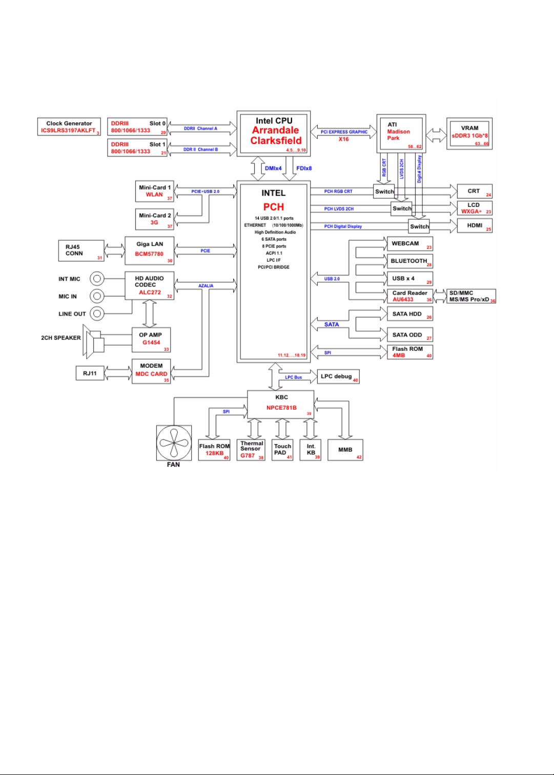
System block diagram
6

www.packardbell.com
Hardware specifications and configurations
CPU
Item Specification
CPU type
Core logic Mobile Intel HM55 Express Chipset
Socket type LGA 1156 (Socket H)
Controllers
Item Controller
Core logic Mobile Intel HM55 Express Chipset
VGA
n
Intel Core i3 Processors: 330M (2.13 GHz), M620 (2.5 GHz), 350M (2.26 GHz)
n
Intel Core i5 Processors: 430M (2.26 GHz), 520M (2.4 GHz), 540M (2.53 GHz)
n
Intel Core i7 Processors: 620M (2.66 GHz)
n
Discrete model: ATI Madison Pro / Park XT with DDR3-800 1 GB VRAM
n
UMA model: Integrated in the Mobile Intel HM55 Express Chipset
LAN Broadcom BCM57780
USB 2.0 Mobile Intel HM55 Express Chipset
Bluetooth Broadcom BCM2046
Wireless 802.11
Memory card reader Alcor AU6433
Audio codec Realtek ALC272
n
Intel WiFi Link 5100
n
Intel WiFi Link 5300
n
Atheros AR5B91/HB93 b/g/n
n
Atheros XB63 b/g
BIOS
Item Specification
BIOS vendor Phoenix
BIOS version v1.06
7

Item Specification
Supported protocols
BIOS password control Manually set
n
ACPI 1.0b/2.0/3.0 compliance
n
PCI 2.2
n
System/HDD password
n
Security Control
n
INT 13H Extensions
n
PnP BIOS 1.0a SMBIOS 2.4
n
BIOS Boot Specification
n
Simple Boot Flag 1.0
n
Boot block
n
PCI Bus Power Management Interface Specification
n
USB Specification 1.1/2.0
n
IEEE 1394 1.0
n
USB/1394 CD-ROM Boot Up support
n
PC Card Standard 1995 (PCMCIA 3.0 Compliant Device)
n
IrDA 1.0
n
Intel AC97 CNR Specification
n
WfM 2.0
n
PXE 2.1
n
Boot Integrity Service Application Program Interface (BIS) 1.0
n
PC99a and Mobile PC2001 Compliant
Memory
Item Specification
CHAPTER 1: System specifications
Memory controller Built-in
Memory size 0 MB (no on-board memory)
SO-DIMM socket number 2 sockets
Supports maximum
memory size
4GB
Supports SO-DIMM type DDR3
Supports data rate 800/1066/1333 MT/s
Supports SO-DIMM
204-pin SO-DIMM
package
Memory module
combinations
You can install memory modules in any combination as long as they match the above
specifications.
8
Hard disk drive
Item
www.packardbell.com
Models Seagate
Capacity (MB) 160000 250000 320000 500000 640000
Bytes per sector 512 512 512 512
Data heads 3/4 4 4 4
Drive Format
Disks 2 2 2 2
Spindle speed
(RPM)
Performance Specifications
Buffer size 8 MB 8 MB 8 MB 8 MB 8 MB
Interface SATA SATA SATA SATA SATA
Max. media
transfer rate
(disk-buffer,
Mbytes/s)
ST9160314AS
To sh i ba
MK1655GSX
HGST
HTS545016B9A
300
WD
WD1600BEVT22ZCTO
5400 RPM 5400 RPM 5400 RPM 5400 RPM 5400 RPM
540 540 850 3.0 GB/s (Max.)
Seagate
ST9250315AS
To sh ib a
MK2555GSX
HGST
HTS545025B9A
300
WD
WD2500BEVT-22Z
CT0
Seagate
ST9320325AS
Toshiba
MK3263GSX
HGST
HTS545032B9A
300
WD
WD3200BEVT-22Z
CT0
Seagate
ST9500325AS
To sh i ba
MK5055GSX
HGST
HTS545050B9A
300
WD
WD5000BEVT-22Z
AT0
Buffer to Host
WD
WD6400BEVT-22A
0RT0
3.0 GB/s
DC Power Requirements
Voltage
tolerance
5V (DC) +/- 5% 5V (DC) +/- 5% 5V (DC) +/- 5% 5V (DC) +/- 5% 5V (DC) +/- 5%
Optical drive
Item Specification
Models HLDS Super-Multi Drive GT30N
Performance Specification
Transfer rate
(KB/sec)
Buffer Memory 2MB
Interface SATA
PLDS Super-Multi Drive DS-8A4SH
Sony Super-Multi Drive AD-7585H
Toshiba Super-Multi Drive TS-L633C
Sustained:
n
with CD: Max 3.6Mbytes/sec
n
with DVD: Max 10.08Mbytes/sec
HLDS BD Combo 1CT21N
PLDS BD Combo DS-4E1S
Pioneer BD Combo BDC-TD01RS
Sony BD Combo 4X BC-5500H
Sustained:
n
with CD: Max 3.6Mbytes/sec
n
with DVD: Max 10.8Mbytes/sec
n
with BD: Max 11Mbytes/sec
n
for CD/DVD: 2MB
n
for BD: 4.5MB
9

Item Specification
CHAPTER 1: System specifications
Applicable disc
format
CD: CD-DA, CD-ROM, CD-ROM XA, Photo CD (multi-session), Video CD, Cd-Extra (CD+), CD-text
DVD: DVD-VIDEO, DVD-ROM, DVD-R (3.9GB, 4.7GB) DVD-R DL, DVD-RW, DVD-RAM, DVD+R,
DVD+R DL, DVD+RW
CD:
CD-DA (Red Book) - Standard Audio CD & CD-TEXT
CD-ROM (Yellow Book Mode1 & 2) - Standard Data
CD-ROM XA (Mode2 Form1 & 2) - Photo CD, Multi-Session
CD-I (Green Book, Mode2 Form1 & 2, Ready, Bridge)
CD-Extra/ CD-Plus (Blue Book) - Audio & Text/Video
Video-CD (White Book) - MPEG1 Video
CD-R (Orange Book Part)
CD-RW & HSRW (Orange Book Part Volume1 & Volume 2
Super Audio CD (SACD) Hybrid type
US & US+ RW
DVD:
DVD-ROM (Book 1.02), DVD-Dual
DVD-Video (Book 1.1)
DVD-R (Book 1.0, 3.9G)
DVD-R (Book 2.0, 4.7G) - General & Authoring
DVD+R (Version 1.0)
DVD+RW
DVD-RW (Non CPRM & CPRM)
DVD°”R Dual
Blu-Ray:
BD-R, BD-R DL, BD-RE, BD-RE DL
Loading
mechanism
Load: Manual
Release: (a) Electrical (Release Button), (b) ATAPI command, (c) Emergency
Power Requirement
Input Voltage 5 V +/- 5% (Operating) 5 V +/- 5% (Operating)
LCD
Item Specification
Vendor
Screen diagonal (mm) 15.6 inches
Resolution support (pixels)
Pixel pitch 0.204 x 0.204
Pixel arrangement R.G.B. Vertical Stripe
Display mode Normally white
Typical white luminance
(brightness)
Luminance uniformity 1.25 max.
Contrast ratio 400:1, 500:1 or 650:1
n
AUO
n
CMO
n
Innolux
n
LG
n
Samsung
n
800×600
n
1024×768
n
1280×720
n
1280*768
n
1360×768
n
1366×768
200 or 220 nits
10

Item Specification
°
Response time (msec) 8
Nominal input voltage VDD +3.3V
Viewing angle (degree)
Horizontal: Right/Left
Vertical: Upper/Lower
Temperature range( C)
Operating
Storage (shipping)
45/45
15/35
0 to +50
-40 to +60
Keyboard
Item Specification
Keyboard controller Winbond WPC773
Total number of keypads 99/100/103-key
Windows logo key Yes
www.packardbell.com
Internal & external
keyboard work
simultaneously
Plug USB keyboard to the USB port directly
Pointing device
Item Specification
Type
Buttons Left/Right
n
Synaptics TM00540-001 Touchpad
n
ALPS KGDFF0031A Touchpad
Memory card reader
Item Specification
Controller Alcor AU6433
Cards supported Support 5-in-1 card reader (MMC, MS, MS-pro, SD, and xD)
Compliancy
n
Complies to SDIO Host Interface Specification Rev 1.0
n
Supports MMC, MMCplus, SD Memory, and SDIO cards
n
SDIO Version 1.10 compliant with High-Speed Mode
n
SD Host Interface Specification v1.0
n
SD Host Interface Specification v2.0
n
SD HC (High Capacity SD memory card)
n
Supports SD memory card, with CPRM security
n
Complies to MultiMediaCard™ Version 4.0
n
Supports Memory Stick™ and MS PRO media cards
n
Supports xD-Picture™ card and SmartMedia™ cards
11

CHAPTER 1: System specifications
Audio
Item Specification
Audio codec Realtek ALC272
Audio onboard or optional Built-in
Mono or stereo Stereo
Resolution 24-bit DAC and ADC
Compatibility HD Audio
Sampling rate 192 kHz maximum sample rate
Internal microphone With webcam
Internal speaker/quantity 2 speakers
Wired LAN
Item Specification
LAN chipset Broadcom BCM57780
Supports LAN protocol 10/100/1000 Mbps
LAN connector type RJ45
LAN connector location Left side
Features
n
Integrated 10/10/1000 BASE-T transceiver
n
PCI v2.2 compliant
n
Wake on LAN support meeting ACPI requirements
Bluetooth
Item Specification
Chipset Broadcom BCM2046
Data throughput 2.1 Mbit/s
Protocol Bluetooth 2.1
Interface USB (board level)
Connector type Wireless via Bluetooth protocols
12

www.packardbell.com
Wireless LAN
Item Specification
Chipset
Data throughput 11~54 Mbps, up to 270 Mbps for Draft-N
Protocol
Interface PCI bus (mini PCI socket for wireless module)
n
Intel WiFi Link 5100
n
Intel WiFi Link 5300
n
Atheros AR5B91/HB93 b/g/n
n
Atheros XB63 b/g
n
WNC WiMAX
n
IEEE 802.11a
n
IEEE 802.11b
n
IEEE 802.11g
n
IEEE 802.11 Draft-N
n
IEEE 802.16e
USB
Item Specification
Chipset Mobile Intel HM55 Express Chipset
USB compliancy level 2.0
OHCI USB 1.1 and USB 2.0 host controller
Number of USB ports 4
Location
n
Two on the left side
n
Two on the right side
Buttons/Indicators/Ports
Item Specification
Buttons
Indicators
Ports
n
Power button
n
Capacitive touch keys
n
Bluetooth
n
Hard drive
n
Num lock
n
Caps lock
n
Battery charge
n
Power
n
USB (four)
n
External display (VGA) port
n
Ethernet (RJ45)
n
Modem (RJ11)
n
Headphone/SPDIF Audio Out
n
Microphone in
n
DC in jack for AC adapter
n
5-in-1 card reader (SD™, MMC, MS, MS PRO, xD)
n
HDMI™ port with HDCP support
13

CHAPTER 1: System specifications
Camera
Item Specification
Model Chicony 0.3M DV Calla / Camellia
Interface USB 2.0
Resolution 0.3 M pixels (640x480)
Signal to noise ratio 42 dB
Sensor CMOS 1/4
Power 5 V
Built-in microphone Yes
LED No
Fans
CPU temperature (° C) Fan speed (rpm) Acoustic level (dBA)
45-50 0-3000 29
55-66 0-3300 33
68-74 3300-3800 38
78-83 3800-4100 40
86-91 4100-4800 40
Throttling 50%: % is controlled by operating system. Temperature point is 95 °C. OS shut down at 100 °C; H/W
shut down at 105 °C
Battery
Item Specification
Vendor
type Li-ion
Pack capacity 4400mAH–5800mAH
Number of battery cell 6
Package configuration 3 cells in series, 2 series in parallel
n
Panasonic
n
Samsung
n
Sanyo
n
Sony
n
Simplo
Normal voltage 11.1V
Charge voltage 12.6V (max)
14

www.packardbell.com
Power supply
Item Specification
Vendor
Input rating 90V AC to 264V AC, 47Hz to 63Hz
Maximum input AC current 1.7A (max)
Output rating 19V DC, 3.42A, 65W
n
n
n
Delta
Liteon
Hipro
Power savings
ACPI mode Power Management
Mech. Off (G3) All devices in the notebook are turned off completely.
Soft Off (G2/S5) OS initiated shutdown. All devices in the notebook are turned off completely.
Working (G0/S0) Individual devices such as the CPU and hard disc may be power managed in this state.
Suspend to RAM (S3)
n
CPU set power down
n
VGA suspend
n
PCMCIA suspend
n
Audio power down
n
Hard drive power down
n
Optical drive power down
n
Super I/O low power mode
Save to Disk (S4) Also called Hibernation mode. System saves all system states and data onto the disc prior
to powering off the whole system.
15
CHAPTER 1: System specifications
Ventilation fan
Ethernet
jack
USB
port
Kensington
lock slot
Power
connector
Monitor
port
HDMI out
jack
Microphone
jack
Headphone
jack
Memory card
reader
Notebook product tour
Important
Case color may vary from that shown in the pictures.
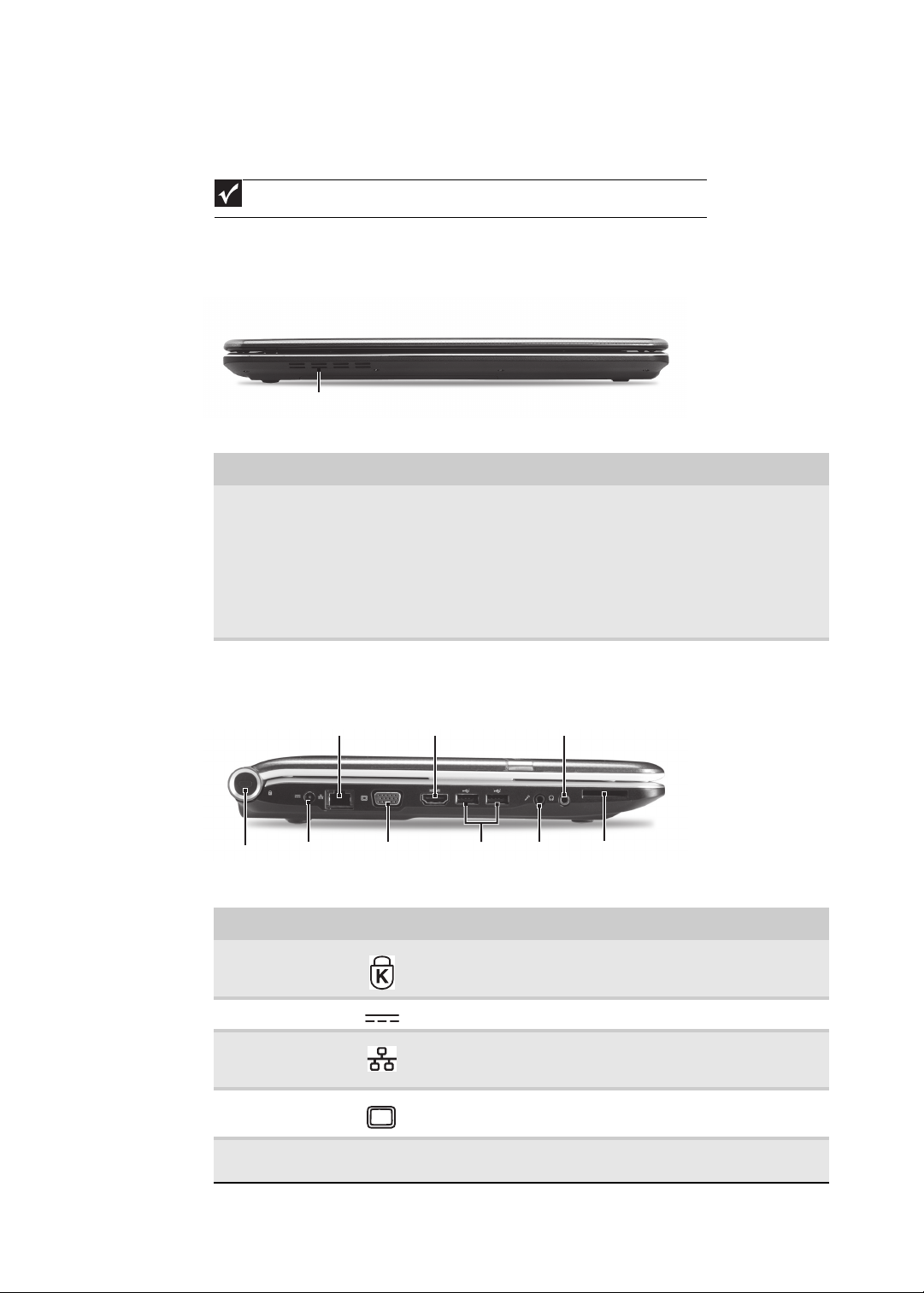
Front View
Component Icon Description
Left View
Ventilation fan Helps cool internal components.
Warning: Do not work with the notebook resting on your lap. If
the air vents are blocked, the notebook may become hot enough
to harm your skin.
Caution: Do not block or insert objects into these slots. If these
slots are blocked, your notebook may overheat resulting in
unexpected shutdown or permanent damage to the notebook.
Caution: Provide adequate space around your notebook so air
vents are not obstructed. Do not use the notebook on a bed, sofa,
rug, or other similar surface.
Component Icon Description
Kensington™
lock slot
Secure your notebook to an object by connecting a Kensington
cable lock to this slot.
16
Power connector Plug the AC adapter cable into this connector.
Ethernet jack Plug an Ethernet network cable into this jack. Plug the other end
Monitor port Plug an analog VGA monitor or projector into this port.
HDMI out jack
HDMI
of the cable into a cable modem, DSL modem, or an Ethernet
network jack.
Plug an HDMI device, such as a high definition television, into this
optional jack.
www.packardbell.com
DVD drive
USB port
Modem
jack
Power
button
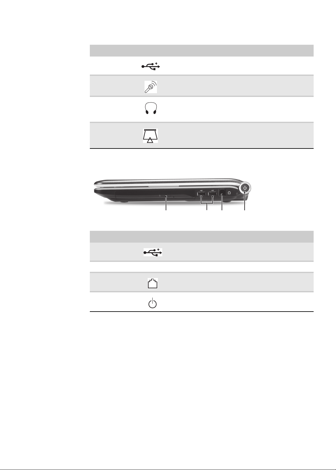
Component Icon Description
Right View
USB port Plug USB devices (such as a diskette drive, flash drive, printer,
Microphone jack Plug a microphone into this jack.
Headphone jack Plug amplified speakers or headphones into this jack. The built-in
Memory card
reader
scanner, camera, keyboard, or mouse) into these ports.
speakers are turned off when speakers or headphones are
plugged into this jack.
Headphone with SPDIF support
Insert a memory card from a digital camera, MP3 player, PDA,
or cellular telephone into the memory card reader. The memory
card reader supports Memory Stick®, Memory Stick Pro®,
MultiMediaCard™, Secure Digital™, and xD-Picture Card™cards.
Component Icon Description
USB port Plug a USB device (such as a diskette drive, flash drive, printer,
DVD drive Insert CDs or DVDs into this drive.
Modem jack Plug a dial-up modem cable into this optional jack.
Power button Press to turn the power on or off. You can also configure the
scanner, camera, keyboard, or mouse) into this port.
power button for Sleep/Resume mode.
17
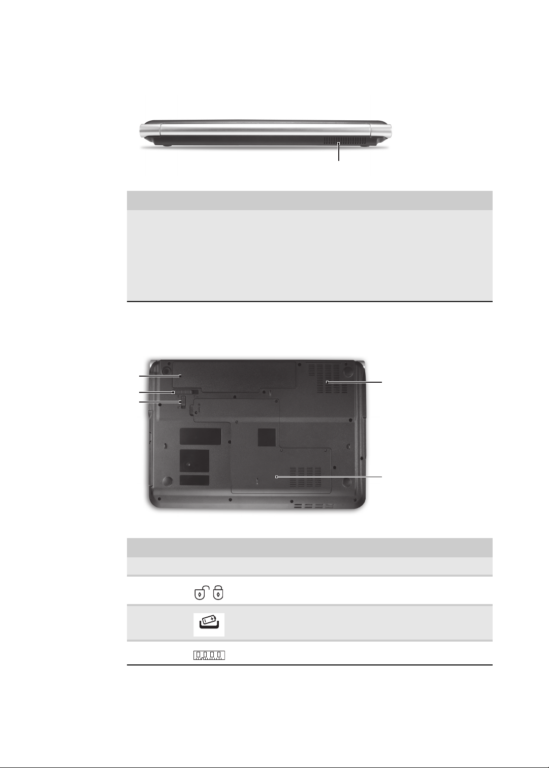
Rear View
Ventilation fan
Ventilation
slots and
cooling fan
Battery
Battery
lock
Battery latch
Memory/
Hard drive
bay
CHAPTER 1: System specifications
Component Icon Description
Bottom View
Ventilation fan Helps cool internal components.
Warning: Do not work with the notebook resting on your lap. If
the air vents are blocked, the notebook may become hot enough
to harm your skin.
Caution: Do not block or insert objects into these slots. If these
slots are blocked, your notebook may overheat resulting in
unexpected shutdown or permanent damage to the notebook.
Caution: Provide adequate space around your notebook so air
vents are not obstructed. Do not use the notebook on a bed, sofa,
rug, or other similar surface.
18
Component Icon Description
Battery Provides power when the notebook is not plugged into AC power.
Battery lock Slide to unlock the battery.
Battery latch Slide to release the battery.
Memory bay Memory modules are located in this bay.
www.packardbell.com
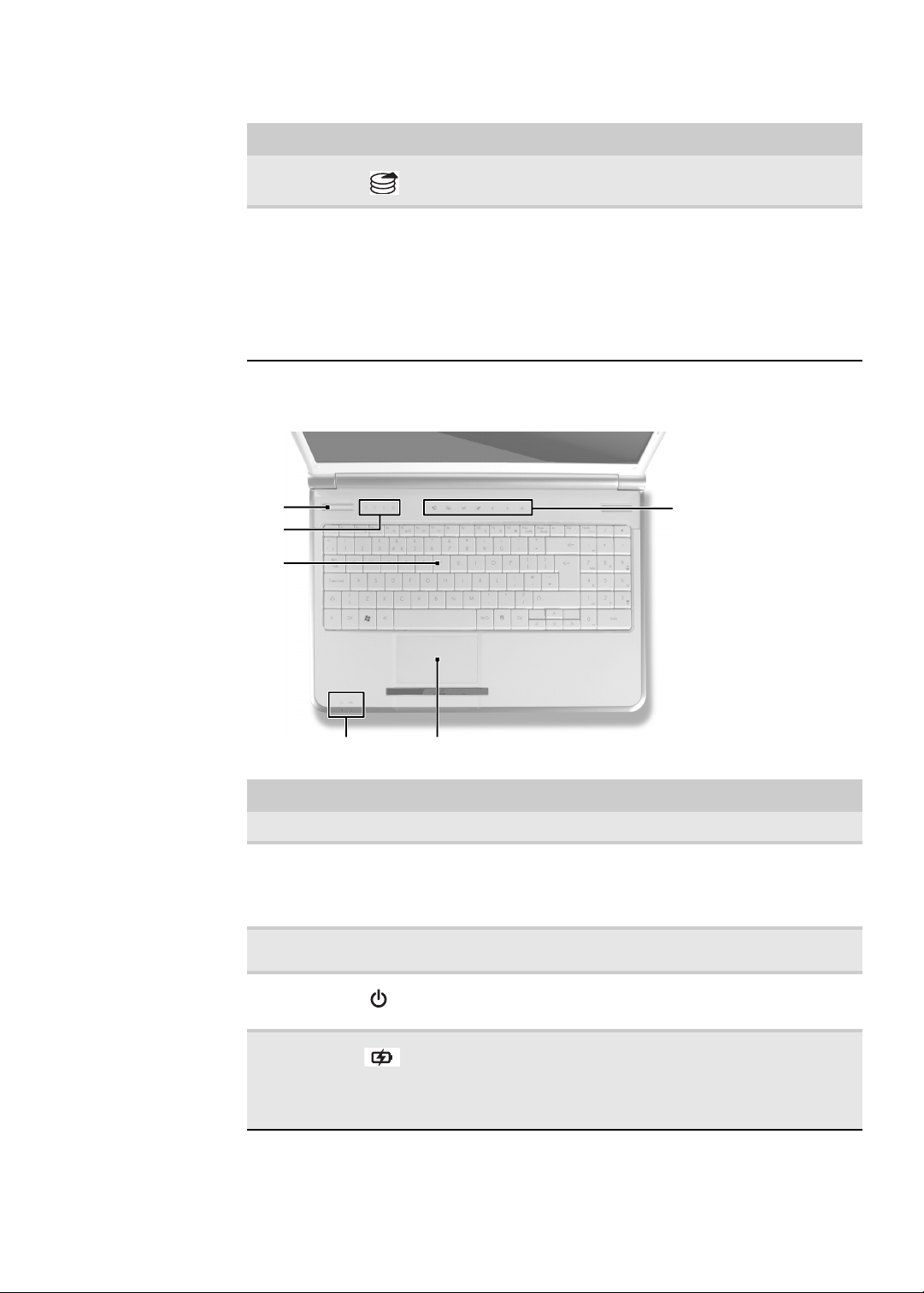
Keyboard
Capacitive
touch keys
Status
indicators
Speakers
Touchpad
Power/Battery
indicators
Component Icon Description
Keyboard area
Hard drive
bay
Ventilation
slots and
cooling fan
The hard drive is located in this bay.
Helps cool internal components.
Warning: Do not work with the notebook resting on your lap. If the air
vents are blocked, the notebook may become hot enough to harm your
skin.
Caution: Do not block or insert objects into these slots. If these slots
are blocked, your notebook may overheat resulting in unexpected
shutdown or permanent damage to the notebook.
Caution: Provide adequate space around your notebook so air vents
are not obstructed. Do not use the notebook on a bed, sofa, rug, or
other similar surface.
Component Icon Description
Speakers Left and right speakers deliver stereo audio output.
Capacitive
hotkeys /
status
indicators
Keyboard Provides all the features of a full-sized, computer keyboard. For more
Power
indicator
Battery charge
indicator
Inform you when there is media activity or when a button has been
pressed that affects how the keyboard is used. When a function is
enabled, the touch key is lit up. For more information, see “Using the
status indicators” on page 21 and “Using the capacitive touch keys” on
page 24.
information, see “Using the keyboard” on page 21.
n
LED on - Notebook is on.
n
LED blinking - Notebook is in Sleep or Hybrid Sleep mode.
n
LED off - Notebook is off.
n
n
n
n
Important: This LED only lights up when your notebook is connected to
AC power or the battery charge is very low.
LED orange - Battery is fully charged.
LED blinking orange - Battery is charging.
LED blinking red - Battery charge is very low.
LED solid red - Battery is malfunctioning.
19
CHAPTER 1: System specifications
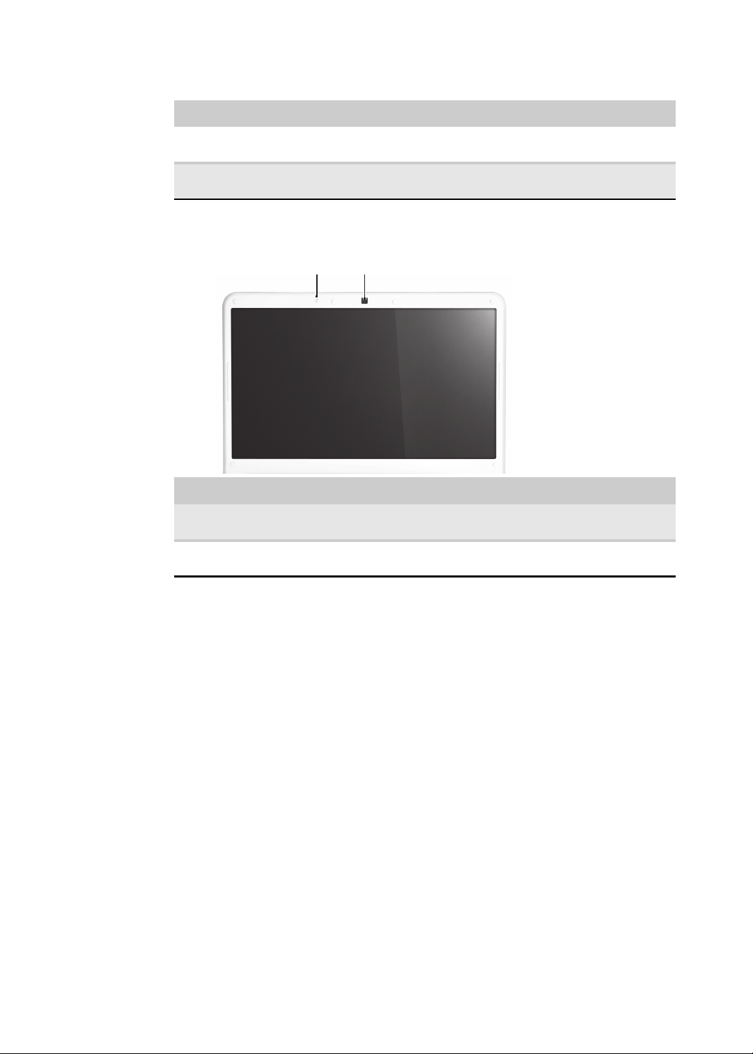
We bc am
Microphone
Component Icon Description
LCD panel
Touchpad Provides all the functionality of a mouse. For more information, see
Capacitive
touch keys
Component Icon Description
Webcam Use to let others see who they are communicating with when making
“Using the touchpad” on page 25.
Press to access capacitive touch key function. For more information, see
“Using the capacitive touch keys” on page 24.
VoIP calls. For more information, see “Using the webcam” on page 26.
Microphone Use to talk through when making Voice over Internet Protocol (VoIP)
calls.
20
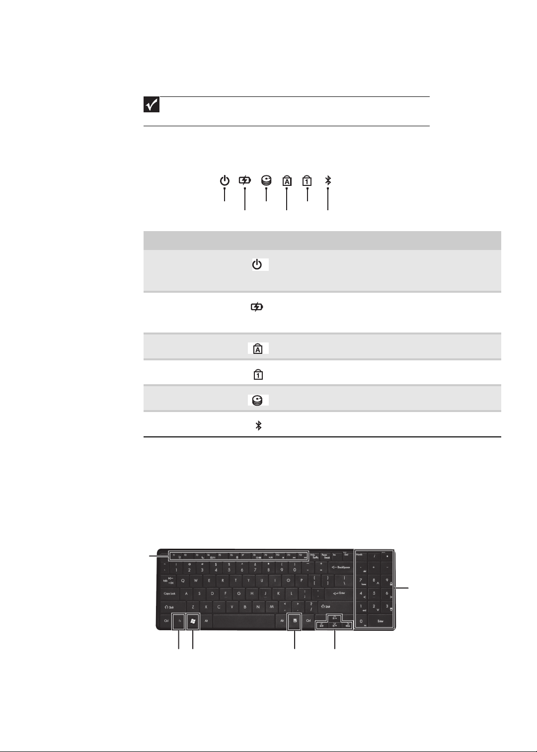
Using the status indicators
Bluetooth
HDD
Caps lock
Num lock
Battery
Power
Function
keys/
System
keys
FN
key
Windows key
Application key
Arrow keys
Numeric
keypad/
Navigation
keys
Important
If none of the indicators are on, you may need to press FN+F1 to toggle the
status indicators on.
Status indicators inform you when a drive is being used or when a button has been
pressed that affects how the keyboard is used. The status indicators are located
below the screen.
Indicator Icon Description
Power indicator
Battery charge
indicator
Caps lock
Num lock
Hard drive
Bluetooth
www.packardbell.com
n
LED on - Notebook is on.
n
LED blinking - Notebook is in Sleep or Hybrid Sleep
mode.
n
LED off - Notebook is off.
n
LED blue - Battery is fully charged.
n
LED red - Battery is charging.
Important: This LED only lights up when your notebook is
connected to AC power.
n
LED on - Caps lock is turned on.
n
LED off - Caps lock is turned off.
n
LED on - Num lock is turned on.
n
LED off - Num lock is turned off.
n
LED blinking - The drive is being accessed.
n
LED off - The drive is not being accessed.
n
LED on - Bluetooth communication is turned on.
n
LED off - Bluetooth communication is turned off.
Using the keyboard
Your notebook features a full-size keyboard that functions the same as a desktop
computer keyboard. Many of the keys have been assigned alternate functions,
including shortcut keys for Windows and function keys for specific system
operations.
21
CHAPTER 1: System specifications
Key types
The keyboard has several different types of keys. Some keys perform specific
actions when pressed alone and other actions when pressed in combination with
another key.
Key type Icon Description
Function keys Press these keys labeled F1 to F12 to perform actions in programs.
System keys Press these colored keys in combination with the F
Navigation keys Press these keys to move the cursor to the beginning of a line,
F
N key Press the FN key in combination with a colored system key to
Windows key Press this key to open the Windows Start menu. This key can also
Application key Press this key for quick access to shortcut menus and help
Arrow keys Press these keys to move the cursor up, down, right, or left.
For example, pressing F1 may open help.
Each program uses different function keys for different purposes.
See the program documentation to find out more about the
function key actions.
perform specific actions. For more information, see “System key
combinations” on page 22.
to the end of a line, up the page, down the page, to the beginning
of a document, or to the end of a document.
perform a specific action.
be used in combination with other keys to open utilities like
F (Search utility), R (Run utility), and E (Computer window).
assistants in Windows.
N key to
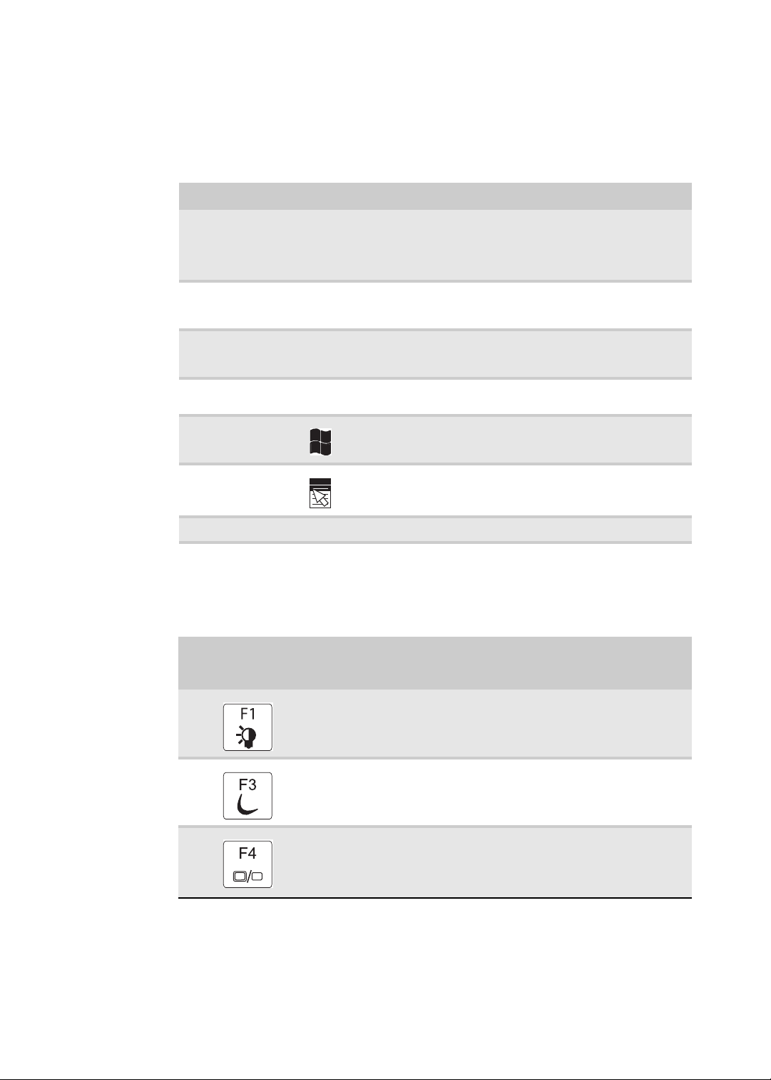
System key combinations
When you press the FN key and a system key at the same time, your notebook
performs the action identified by the text or icon on the key.
22
Press and hold FN,
then press this
system key...
To...
Turn the capacitive touch key LEDs on or off. For more information, see
“Using the status indicators” on page 21.
Enter Sleep mode or Hybrid Sleep mode. Press the power button to
leave Sleep mode.
Toggle the notebook display in the following order:
n
The LCD
n
An external monitor or projector (a monitor or projector must be
plugged into the monitor port or HDMI port on your notebook)
n
Both displays at the same time
www.packardbell.com
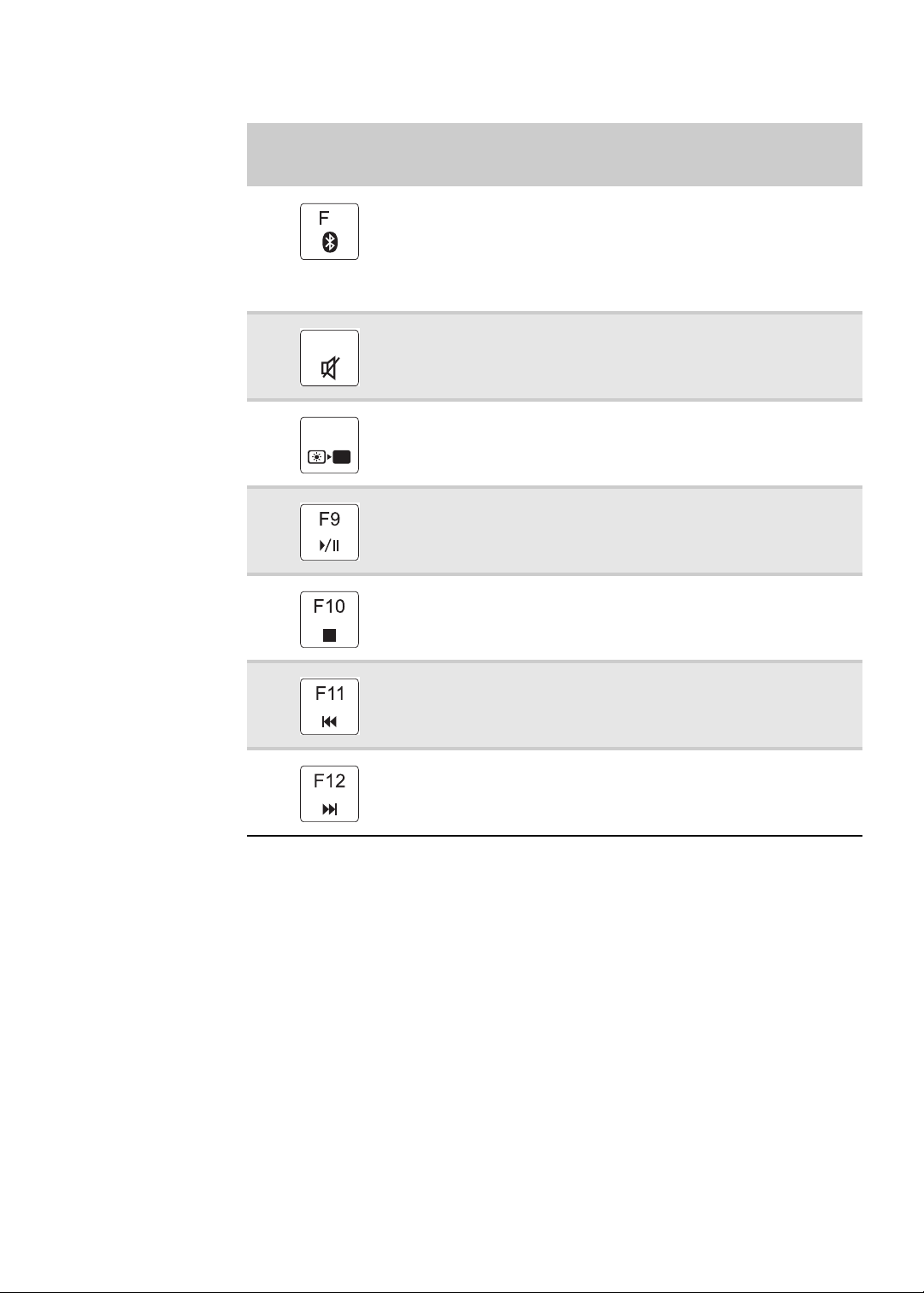
Press and hold FN,
then press this
system key...
6
F7
F8
To .. .
Turn the optional Bluetooth radio on or off.
Warning: Radio frequency wireless communication can interfere with
equipment on commercial aircraft. Current aviation regulations require
wireless devices to be turned off while traveling in an airplane. Bluetooth
communication devices are examples of devices that provide wireless
communication.
Important: The wireless network switch must be in the ON position for
this button to work. For more information, see “Left View” on page 16.
Mute the sound. Press the key combination again to restore the sound.
Turns the display screen backlight off to save power. Press any key to
return.
Play/ Pause—Plays or pauses the CD or DVD.
Stop—Stops playing the CD or DVD.
Previous—Skips back one CD track or DVD chapter.
Next—Skips ahead one CD track or DVD chapter.
23
CHAPTER 1: System specifications
PowerSave
Touchpad
toggle
Wireless
switch
Decrease
volume
Increase
volume
Mute
(only for certain models)
MyBackup
Programmable
key
Touchpad
toggle
Wireless
switch
Decrease
volume
Increase
volume
Mute
(only for certain models)
MyBackup
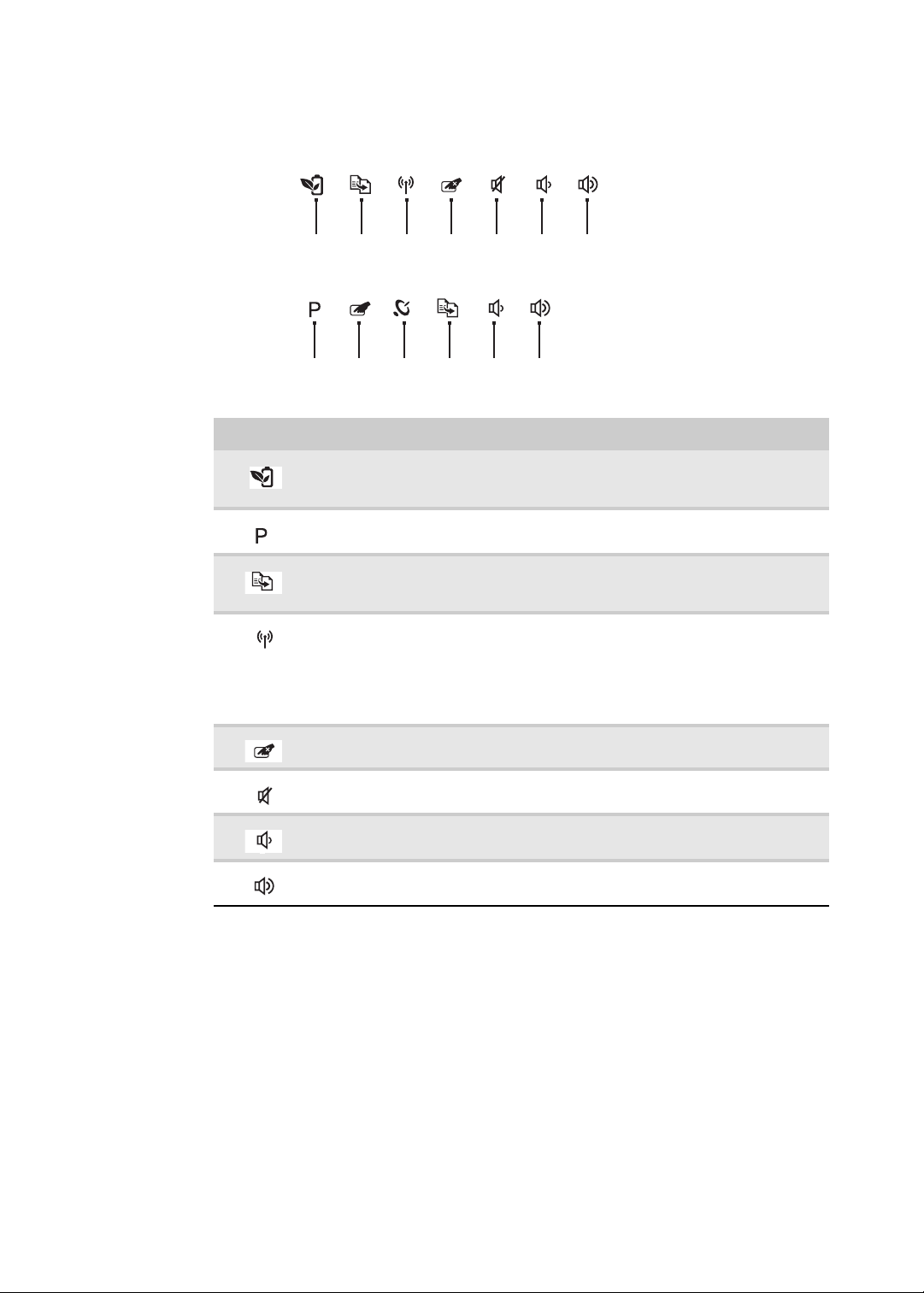
Using the capacitive touch keys
Button Description
PowerSave key—Press to put the notebook into power-saving mode. The
button lights up red when this happens. Press this key again to return to
your previous settings.
Programmable key—The programmable key will run the Launch Manager, you can
assign an application as your needed. (only for certain models)
MyBackup key—Press to create a data backup in three easy steps: select
source, select destination, and backup schedule (manual or automatic).
The button lights up red during the backup process.
Wireless switch—Turn the optional IEEE 802.11 wireless network radio on or off.
For more information, see “Wireless Ethernet Networking” in your online User
Guide.
Warning: Radio frequency wireless communication can interfere with equipment
on commercial aircraft. Current aviation regulations require wireless devices to be
turned off while traveling in an airplane. IEEE 802.11 communication devices are
examples of devices that provide wireless communication.
Touchpad toggle—turn the internal touchpad on and off.
Mute—mutes the sound. Press again to restore the sound.
Decrease volume—press to decrease volume.
Increase volume—press to increase volume.
24

Using the touchpad
Left button
Right button
Touchpad
When you move your finger on the touchpad, the pointer (arrow) on the screen
moves in the same direction. You can use the scroll zone to scroll through
documents. Use of the scroll zone may vary from program to program.
www.packardbell.com
You can use the left and right buttons below the touchpad to select objects.
To... Do this...
Move the pointer
on the screen.
Select an object
on the screen.
Move your finger around on the
touchpad. If you run out of space
and need to move the pointer
farther, lift your finger, move it to
the middle of the touchpad, then
continue moving your finger.
Position the pointer over the
object. Quickly press and
release the left button once. This
action is called clicking.
25

CHAPTER 1: System specifications
Webcam
Microphone
To .. . Do this...
Start a program
or open a file or
folder.
Access a
shortcut menu
or find more
information
about an object
on the screen.
Move an object
on the screen.
Position the pointer over the
object. Press the left button
twice in rapid succession. This
action is called double-clicking.
Position the pointer over the
object. Quickly press and
release the right button once.
This action is called
right-clicking.
Position the pointer over the
object. Press the left button and
hold it down, then use the
touchpad to move (drag) the
object to the appropriate part of
the screen. Release the button
to drop the object where you
want it.
Using the webcam
You can use the optional webcam with many of the available Internet chat
programs to add video and audio to your chat session. In addition, by using the
software included with the webcam, you can take pictures or create video clips.
26

CHAPTER2
• BIOS setup utility
• BIOS recovery
• Clearing a BIOS password
• Unlocking the hard drive
System utilities
27

CHAPTER 2: System utilities
BIOS setup utility
The BIOS setup utility is a hardware configuration program built into the notebook’s
BIOS (Basic Input/Output System). The notebook was shipped already properly
configured and optimized. However, if the user encounters configuration problems,
you may need to run Setup.
To run the BIOS Setup Utility:
1 Turn on the notebook.
If the computer is already turned on, save your data and close all open
applications, then restart the computer.
2 Press F2 when the Press <F2> to enter Setup prompt appears on the bottom
of the screen.
Use the left and right arrow keys to move between selections on the menu
bar.
28

www.packardbell.com
Navigating the BIOS setup utility
Use the keys listed in the legend bar on the bottom of the Setup screen to work
your way through the various menu and submenu screens.
To use the BIOS setup utility:
• To choose a menu, use the left ← and right → arrow keys.
• To choose an item, use the up ↑ and down ↓ arrow keys.
• To change the value of a parameter, press F5 or F6.
• A plus sign (+) indicates the item has sub-items. Press ENTER to expand this
item.
• To load default settings, press F9.
• To save changes made and close the utility, press F10.
1 Press ESC while you are in any of the menu screen to display the Exit menu.
Important
• You can change the value of a parameter if it is enclosed in
square brackets.
• Navigation keys for a particular menu are shown on the bottom
of the screen. Help for parameters are found in the Item Specific
Help part of the screen. Read this information carefully when
making changes to parameter values.
• The screenshots used in this section are for illustration only. The
values displayed may not be the same as those in your computer.
BIOS setup utility menus
The Setup utility has five menus for configuring the various system functions.
These include: Information, Main, Security, Boot, and Exit.
Important
• The screenshots used in this section are for illustration only. The
values displayed may not be the same as those in your computer.
Actual screen information varies by model, installed features, and
location.
• In the descriptive table following each of the screenshot, settings
in boldface are the default settings.
29

CHAPTER 2: System utilities
Information
The Information menu displays a summary of your computer hardware information.
These information are necessary for troubleshooting and may be required when
asking for technical support.
Parameter Description
CPU Type Displays the processor model and speed.
CPU Speed Displays the processor speed.
IDE0 Model Name Displays the model name of the hard drive installed on the
IDE0 Serial Number Displays the serial number of the hard drive installed on the
ATAPI Model Name Displays the model name of the installed optical drive.
System BIOS
Version
VGA BIOS Version Displays the VGA firmware version.
KBC Version Displays the keyboard controller version.
Serial Number Displays the system serial number.
Asset Tag Number Displays the system asset tag number
Product Name Displays the official model name of the computer.
Manufacturer Name Displays the name of the computer manufacturer.
UUID Number Displays the computer’s UUID (universally unique identifier).
primary IDE master.
primary IDE master.
Displays system BIOS version.
UUID is an identifier standard used in software construction,
standardized by the Open Software Foundation (OSF) as part
of the Distributed Computing Environment (DCE).
30

www.packardbell.com
Main
Use the Main menu to set the system time and date, and other basic options.
Parameter Description Format/Options
System Time Displays the system time. The time is
expressed in a 24-hour format.
System Date Displays the system date. MM/DD/YYYY
Total Memory Displays the size of system memory detected during boot-up.
Video Memory Displays the size of video memory detected during boot-up.
Quiet Boot Enables or disables the Quiet Boot
function.
When enabled, BIOS setup is in graphical
mode and displays only the computer
brand logo during POST and while booting.
When disabled, BIOS setup is in
conventional text mode and displays the
system Summary Screen.
Network Boot When enabled, a remote host with
appropriate boot image can boot this
computer. (only works with an Ethernet
device.)
F12 Boot Menu Enables or disables the Boot menu during
POST.
HH:MM:SS
(hour:minute:second)
(month/day/year)
Disabled
Enabled
Disabled
Enabled
Disabled
Enabled
31

CHAPTER 2: System utilities
Phoenix SecureCore(tm) Setup Utility
Main
F1
Esc
Help
Exit
Select Item
Select Menu
Change Values
Select Sub-Menu
-/+
Enter
F9
F10
Setup Defaults
S a v e an d Ex it
Information Security Boot Exit
Item Specific Help
Supervisor Password
c o n tr ol s ac ce ss o f th e
whole setup utility.
I t c a n be u se d to b oo t
u p w h en P as sw or d on
boot is enabled.
Supervisor Password s:
User Password s:
:
S e t U se r Pa ss wo rd
Set Password
P a s sw or d on B oo t:
i
i
H D D P as sw or d is
HDD
Set Supervisor Password
Clear
Clear
Clear
[Enter]
[Enter]
[Disabled]
[]Enter
Parameter Description Format/Options
D2D Recovery Enables or disables the D2D Recovery
function. This function allows the user to
create a hidden partition on the hard drive
Disabled
Enabled
to store the operation system. User can
then use this partition to restore the system
to factory defaults by pressing the Alt+F10
keys during system boot-up.
SATA Mode Select the SATA controller operating mode.
When set to AHCI (Advanced Host
AHCI
IDE
Controller Interface), the SATA controller
enables its AHCI and RAID features when
the computer boots up.
When set to IDE, the SATA controller
disables its AHCI and RAID functions when
the computer boots up.
Note: If you do not intend to use the AHCI
or RAID features set this parameter to IDE
to speed up the boot-up time.
Security
Use the Security menu option to set system passwords to protect your computer
from unauthorized use.
.
Parameter Description Option
Supervisor
Password Is
User Password Is Displays the user password status. Clear
HDD Password Is Displays the hard drive password status. Clear
32
Displays the supervisor password status. Clear
Set
Set
Set

www.packardbell.com
Parameter Description Option
Set Supervisor
Password
Set User Password Press Enter to set a user password. When set, this password will
Set HDD
Password
Password on Boot Referred to as the power-on password. When
Caution
When you are prompted to enter a password, you have three tries
before the system halts. Don’t forget your password.
Press Enter to set a supervisor password. When set, this password
will allow the user to access and change all settings in the Setup
Utility.
restrict a user’s access to the Setup menus. Only the following
menus will be accessible:
• System Time and System Date
• All Exit menu options excluding Load Setup Defaults
Note: A supervisor password must first be set before creating a
user password.
If Password on Boot is enabled, the user must enter the user
password each time the notebook is turned on or wakes from
Sleep.
Press Enter to set password for accessing the hard disk drive
(HDD) password. It will be required during boot-up or when waking
from hibernation mode.
enabled, the user or supervisor password will be
required to boot up the system.
Note: A supervisor password must first be set
before creating a user password.
Disabled
Enabled
Setting a password
Note the following reminders before you define a system password:
• The maximum length of password contains 8 alphanumeric characters.
• System passwords are case-insensitive.
• When typing the password, only shaded blocks representing each typed
character are visible.
To set a supervisor password:
1 Press ↑ or ↓ to highlight Set Supervisor Password, then press Enter.
The Set Supervisor Password box opens.
2 Type a password, then press Enter.
33

CHAPTER 2: System utilities
3 Retype the password to verify the first entry, then press Enter.
You will be prompted to save the new password.
4 Press Enter.
5 Press F10 to save the password and close the Setup Utility or you can
proceed to setting a user password.
To set a user password:
1 Press ↑ or ↓ to highlight Set User Password, then press Enter.
The Set User Password box opens.
2 Type a password, then press Enter.
3 Retype the password to verify the first entry, then press Enter.
You will be prompted to save the new password.
4 Press Enter.
5 Press F10 to save the password and close the Setup Utility.
Changing a password
To change a password:
1 Press ↑ or ↓ to highlight the Set Supervisor Password or Set User Password
field, then press Enter.
The Set Supervisor Password or Set User Password box opens.
34
2 Type the current password, then press Enter.
3 Type a new password, then press Enter.
4 Retype the new password to verify the first entry, then press Enter.
You will be prompted to save the new password.
5 Press Enter.
6 Press F10 to save the password and close the Setup Utility or you can
proceed to setting a user password.

www.packardbell.com
Removing a password
To remove a password:
1 Press ↑ or ↓ to highlight the Set Supervisor Password or Set User Password
field, then press Enter.
The Set Supervisor Password or Set User Password box opens.
2 Type the current password, then press Enter.
3 Press Enter twice without entering anything in the new and confirm password
fields.
You will be prompted to confirm the password removal.
4 Press Enter.
5 Press F10 to save the password and close the Setup Utility or you can
proceed to setting a user password.
Resetting a password
If you have forgotten the user password, the computer will continue to function
normally but you will have limited access to the Setup utility.
If you have enabled the Password on Boot field and you forget the supervisor
password, you will not be able to boot up the computer. The same thing applies
if you forget the HDD password.
To clear a lost BIOS password (user or supervisor password) you need to short
the clear password hardware gap located on the system board. Go to page 40
for instructions.
To regain access to your computer if you lose the HDD password, you need to
generate a master password and unlock your hard drive. Go to page 41 for
instructions.
35

CHAPTER 2: System utilities
Phoenix SecureCore(tm) Setup Utility
Main
Item Specific Help
U s e < > o r < > to
select a device, then
p r e ss < F6 > to m ov e it
u p t h e li st , or < F5 >
t o m o ve i t do wn t he
list. Press <Esc> to
escape the menu.
Boot priority order:
F1
Esc
Help
Exit
Select Item
Select Menu
Change Values
Select Sub-Menu
-/+
Enter
F9
F10
Setup Defaults
S a v e an d Ex it
Information Security Boot Exit
2: CD/DVD: XXXXXXXXXXX-XXXXX-(X
3:
4:
5:
6:
Network Boot: XXXXXXXXXXXXXXXX
USB HDD:
USB FDD:
U S B K ey :
7 : U S B CD /D VD R OM :
1: IDE0: XXXXXXXXXXX-(XX)
Boot
Use the Boot menu to set the preferred drive sequence in which the Setup utility
attempts to boot the operating system.
To set boot drive sequence:
1 Press ↑ or ↓ to highlight a bootable device.
2 Press F5 or F6 to move the selected device up or down the boot sequence.
3 Press F10 to save the changes you made and close the Setup utility.
36

www.packardbell.com
Phoenix SecureCore(tm) Setup Utility
Main
Item Specific Help
E x i t Sy st em S et up a nd
save your changes to
CMOS.
F1
Esc
Help
Exit
Select Item
Select Menu
Change Values
Select Sub-Menu
-/+
Enter
F9
F10
Setup Defaults
S a v e an d Ex it
Information Security
Boot
Exit
Exit Discarding Changes
Load Setup Defaults
Discard Changes
Save Changes
Exit Saving Changes
Exit
The Exit menu screen lists options for quitting from the Setup Utility.
Option Description
Exit Saving Changes Saves changes made and closes the Setup utility. Keyboard
shortcut: F10
Exit Discarding
Discards changes made and closes the Setup utility.
Changes
Load Setup Default Loads the factory-default settings for all Setup parameters.
Keyboard shortcut: F9
Discard Changes Discards all changes made to the Setup utility and loads
previous configuration settings.
Save Changes Saves all changes made to the Setup utility.
37

CHAPTER 2: System utilities
BIOS recovery
An interruption during a BIOS flash procedure (e.g. a power outage) can corrupt
the BIOS code, which will cause the system to go into an unbootable state. You
need to access and execute the boot block program to reboot the computer and
recover the regular BIOS code.
Caution
Observe the following when performing a BIOS recovery:
• Make sure the battery pack is installed to the system and that
the computer is connected to a UPS unit during the BIOS
recovery and BIOS flash procedures.
• The BIOS crisis recovery disk should be prepared in a computer
running the Windows XP or Windows Vista OS.
Creating the Crisis Recovery disk
To create the Crisis Recovery disk:
1 Prepare a removable USB storage device with a capacity size greater than
10 MB.
Note that all data on the USB storage device will be cleared during the
creation of the crisis disk.
2 Set up a computer running the Windows XP or Windows Vista OS and plug
in the USB storage device into an available USB port.
3 Decompress the Crisis Package Source.
4 Select WINCRIS.exe and then select Run as administrator.
5 Keep the default settings and then click Start button.
6 When the pop-up warning dialog box appears, click OK to create the crisis
disk.
7 Click No if you do not want to create another crisis disk.
8 Eject and reconnect the USB removable storage device, and make sure it
contains the
BIOS.wph, MINIDOS.sys, and PHLASH16.exe files.
Performing a BIOS recovery
To perform a BIOS recovery:
1 Shut down the BIOS failed-computer.
2 Connect the USB storage device containing the Crisis Recovery disk files
to the failed computer.
3 Press and hold the Fn+Esc keys (this is the BIOS recovery hotkey), then
press the power button.
The BIOS recovery process begins. When the process is complete the
computer will automatically reboot.
4 Disconnect the USB storage device from the computer.
5 Perform a BIOS flash procedure to update the BIOS firmware.
38

Running the Flash utility:
To run the Flash utility:
1 Rename the BIOS file as “XXXXXXX.FD”.
2 Copy the “XXXXXXX.FD” file to a bootable USB device containing the Crisis
Recovery disk files.
3 Turn off the computer.
4 Insert the USB device containing the renamed BIOS file and the Crisis
Recovery disk files to any USB port.
5 Press and hold the Fn+Esc keys (this is the BIOS recovery hotkey), then
press the power button.
6 Release the Fn+Esc keys after POST.
www.packardbell.com
39

CHAPTER 2: System utilities
Discrete model
UMA model
Clearing a BIOS password
To clear a lost BIOS password (user or supervisor password) you need to short
the clear password hardware gap (G102) located on the system board.
Gap Default setting Function
G102 Open (normal) Short to clear the user and supervisor
To clear a BIOS password:
passwords.
1 Turn off the notebook and unplug all the peripherals connected to it.
2 Complete the steps in “Removing the battery” on page 48.
3 Complete the steps in “Removing the bay cover” on page 49.
4 Remove the memory module(s) and locate the G102 gap.
5 Use an electrical conductivity tool to short the two contacts on the hardware
gap together.
6 While resting the tool on the two contacts, plug one end of the AC adapter
into the DC power jack and plug one end to an electrical outlet.
7 Press the power button to turn on the system.
8 After the POST, remove the tool from the hardware gap.
9 Reinstall the memory module(s), battery pack, and the bay cover.
10 Turn on the notebook and press F2 during bootup to access the Setup utility.
11 Press F9 to load the system defaults.
12 Press F10 to save the changes you made and close the setup Utility.
40

www.packardbell.com
Unlocking the hard drive
To regain access to your computer if you lose the HDD password, you need to
generate a master password and unlock the hard drive.
To unlock a hard drive:
1 Open the computer in a DOS environment.
2 Type the following command:
A\> unlock6 XXXXX 00
3 Press Enter to display the command options.
4 Select option 2 (upper case ASCII code), then press Enter.
5 Write down the generated master password.
6 Reboot the computer.
7 In the HDD password prompt, type the master password generated in step 5,
then press
Enter.
41

CHAPTER 2: System utilities
42

CHAPTER3
Replacing notebook components
• Preventing static electricity
discharge
• Preparing the work space
• Required tools
• Preparing the notebook
• Adding or replacing memory
modules
• Replacing the wireless card
• Replacing the hard drive
• Replacing the optical drive
• Replacing the keyboard cover
• Replacing the multimedia
board
• Replacing the keyboard
• Replacing the LCD panel
assembly
• Replacing the palm rest
• Replacing the speakers
• Replacing the touchpad board
• Replacing the modem board
• Replacing the USB board
• Replacing the Bluetooth
module
• Replacing the system board
• Replacing the cooling
assembly
• Replacing the processor
• Replacing the LCD front panel
• Replacing the webcam
• Replacing the LCD
• Replacing the LCD panel
hinge brackets
• Replacing the power button
board
• Replacing the Kensington lock
cap
• Replacing the microphone
• Replacing the antennas
• Replacing the LCD assembly
lid
43

CHAPTER 3: Replacing notebook components
Preventing static electricity discharge
Warning
To avoid exposure to dangerous electrical voltages and moving
parts, turn off your notebook, remove the battery, and unplug the
power cord and network cable before opening the case.
Warning
To prevent risk of electric shock, do not insert any object into the
vent holes of the notebook.
Important
Before performing maintenance on the notebook, you should read
and understand the information in this section.
The components inside your notebook are extremely sensitive to static electricity,
also known as electrostatic discharge (ESD).
Before performing maintenance on the notebook, follow these guidelines:
• Avoid static-causing surfaces such as carpeted floors, plastic, and packing
foam.
• Remove components from their antistatic bags only when you are ready to
use them. Do not lay components on the outside of antistatic bags because
only the inside of the bags provide electrostatic protection.
• Always hold components by their edges. Avoid touching the edge
connectors. Never slide components over any surface.
• Wear a grounding wrist strap (available at most electronics stores) and attach
it to a bare metal part of your workbench or other grounded connection.
• Touch a bare metal surface on your workbench or other grounded object.
Tape
44
Some of the procedures in this guide involve removing tape that secures cables
or components. Two types of tape are used in this notebook:
• Mylar, non-conductive tape is typically transparent, with a red or brown tint.
• Conductive tape is typically grey or silver in color.
If the existing tape cannot be reused, replace it with the same type. Make sure
the replacement tape is of the non-ESD generating kind. Do not use cellophane
tape.

www.packardbell.com
Preparing the work space
Before performing maintenance on the notebook, make sure that your work space
and the notebook are correctly prepared.
• Wear a grounding (ESD) wrist strap, and use a grounded or dissipative work
mat.
• Use a sturdy table. Make sure that the table top is wide enough to hold each
component as you remove it.
• Ensure that clear lighting condition is available to make part identification
easier.
• Keep your work surface free from clutter and debris that may damage
components.
• Use a magnetized screwdriver for removing screws.
• When removing components that are attached to the notebook by a cable,
unplug the cable before removing the screws, when possible, to avoid
damaging the cable.
• As you remove components and screws, lay them toward the rear of your
work surface (behind the notebook) or far enough to the side that your arms
will not accidentally brush them onto the floor.
• To help keep track of screws, try the following:
– Place each component’s screws in their own section of a parts sorter.
– Place each component’s screws next to the component on your work
surface.
– Print the first page of each task, then place the page toward the rear of
your work surface. As you remove screws, place the screws in their
respective section on the page.
– After loosening screws that are deeply recessed in a hole (for example,
on the bottom of the base assembly), you can leave the screws in the
holes if you place small pieces of masking tape over the hole openings.
When reassembling the component, just remove the tape and tighten
the screws.
– When you place flat-headed screws on the work surface, stand them
on their heads to prevent the screws from rolling off the table.
45

CHAPTER 3: Replacing notebook components
Required tools
To disassemble the notebook, you need the following tools:
• Wrist grounding strap (for ESD prevention)
v
• Flat screwdriver
• Conductive mat (for ESD prevention)
v
• Phillips screwdriver
v
• Non-marring plastic scribe
v
46

www.packardbell.com
Preparing the notebook
To prepare the notebook for maintenance:
1 Make sure that the optical disc drive is empty.
2 Turn off the notebook.
3 Close the LCD panel.
4 Disconnect the AC adapter.
5 Disconnect the network cable and all peripheral devices connected to the
notebook.
6 Make sure there is no memory card on the card reader slot. To remove a
memory card:
a Push against the card, as if you were pushing it further into the slot,
letting the card spring out
b Pull the memory card out of its slot.
47

CHAPTER 3: Replacing notebook components
Removing the battery
To remove the battery:
1 Turn the notebook over so the base is facing up.
2 Slide the battery lock to the unlocked position.
3 Slide the battery release latch (a), then remove the battery out of the
notebook (b).
Note
The battery is highlighted with a yellow circle in the above image.
Follow local regulations for battery disposal.
48

www.packardbell.com
Phillips #0 screwdriver
Non-marring plastic scribe
Removing the bay cover
To remove or replace components located on the lower bay, you need to remove
the bay cover first.
Tools you need to complete this task:
To remove the bay cover:
1 Complete the steps in “Preparing the notebook” on page 47.
2 Turn the notebook over so the base is facing up.
3 Loosen the bay cover screws (these screws cannot be removed).
4 Insert a non-marring plastic scribe on the cover’s notch to release the cover
from the computer, and then remove the cover.
49

CHAPTER 3: Replacing notebook components
Phillips #0 screwdriver
Non-marring plastic scribe
Adding or replacing memory modules
Important
Use only memory modules designed for this Packard Bell notebook.
Tools you need to complete this task:
To add or replace memory modules:
1 Complete the steps in “Preparing the notebook” on page 47.
2 Complete the steps in “Removing the bay cover” on page 49.
3 If you are replacing a memory module, go to step 4.
If you installing an additional memory module, go to step 6.
4 Use a non-marring plastic scribe to push out the latches on both sides of
the memory slot until the module tilts upward.
50
5 Remove the memory module from its slot.

www.packardbell.com
6 Insert the new memory module at a 30° angle into an empty memory slot,
and then press it down until it clicks into place.
The module is keyed so it can only be inserted in one direction. If the module
does not fit, make sure that the notch in the module lines up with the tab in
the memory slot.
7 Reinstall the bay cover.
51

CHAPTER 3: Replacing notebook components
Phillips #0 screwdriver
Non-marring plastic scribe
Replacing the wireless card
Tools you need to complete this task:
Screws removed during this task:
• 1 black M2×5 (wireless card)
To replace the wireless card:
1 Complete the steps in “Preparing the notebook” on page 47.
2 Complete the steps in “Removing the bay cover” on page 49.
3 Detach the bar code sticker covering the antenna cables.
4 Unplug the antenna cables. Note which color cable corresponds to each of
the connectors.
Important
The number of antenna cables varies depending on the type
of wireless card installed on the notebook. IEEE 802.11n
cards typically have three antenna cables. Other types of
wireless cards usually have only two antenna cables.
52
5 Move the antenna cables away from the wireless card screw.

www.packardbell.com
6 Remove the screw securing the wireless card.
7 Pull the card out of the slot.
8 Insert the new wireless card at a 30° angle into the empty Mini Card slot.
The card is keyed so it can only be inserted in one direction. If the card does
not fit, make sure that the notch in the card lines up with the tab in the card
slot.
9 Secure the new wireless card with the screw removed in step 6.
10 Reconnect the antenna cables to the connectors.
11 Reinstall the bay cover.
53

CHAPTER 3: Replacing notebook components
Phillips #0 screwdriver
Non-marring plastic scribe
Replacing the hard drive
Tools you need to complete this task:
Screws removed during this task:
• 1 black M2×5 (hard drive)
• 2 chrome M3×3 (hard drive bracket)
To replace the hard drive:
1 Complete the steps in “Preparing the notebook” on page 47.
2 Complete the steps in “Removing the bay cover” on page 49.
3 Remove the hard drive screw.
54
4 Grasp the black mylar tab and use it to disengage the hard drive from its connector,
and then remove the drive from its compartment.

www.packardbell.com
5 If your new hard drive already includes the hard drive bracket, go to step 8.
If you need to use the bracket from the old hard drive, go to step 6.
6 Remove the screws that secure the hard drive bracket, and then detach the
bracket from the drive.
7 Place the bracket on the new drive and secure it with the two screws removed
in step 6.
8 Slide the new hard drive into the hard drive compartment and make sure
it’s properly engaged to the SATA1 connector.
9 Secure the new drive to the system board with the screw removed in step 6.
10 Reinstall the bay cover.
55

CHAPTER 3: Replacing notebook components
Phillips #0 screwdriver
Non-marring plastic scribe
Replacing the optical drive
Tools you need to complete this task:
Screws removed during this task:
• 1 black M2.5×6 (optical drive)
• 1 chrome M2×3 (optical drive bracket)
To replace the optical drive:
1 Complete the steps in “Preparing the notebook” on page 47.
2 Complete the steps in “Removing the bay cover” on page 49.
3 Remove the optical drive screw.
56
4 Use the non-marring plastic scribe to carefully push the optical drive out of
the drive bay, and then slide the drive out.

www.packardbell.com
5 If your new optical drive already has it’s own bracket and bezel, go to step 10.
If you need to use the bracket and bezel from the old optical drive, perform
steps 6–9 as necessary.
6 Detach the bezel from the old optical drive.
7 Remove the screws that secure the optical drive bracket, and then detach
the bracket from the drive.
8 Attach the bezel to the new optical drive.
9 Attach the bracket to the new optical drive and secure it with the screw
removed in step 7.
10 Slide the new optical drive into the drive bay and make sure it’s properly
engaged to the ODD1 connector.
11 Secure the new drive to the system board with the screw removed in step 3.
12 Reinstall the bay cover.
57

CHAPTER 3: Replacing notebook components
Phillips #0 screwdriver
Flat screwdriver or Non-marring plastic scribe
Replacing the keyboard cover
Tools you need to complete this task:
Screws removed during this task:
• 3 black M2.5×6 (keyboard cover)
To replace the keyboard cover:
1 Complete the steps in “Preparing the notebook” on page 47.
2 Complete the steps in “Removing the battery” on page 48.
3 Remove the screws securing the keyboard cover.
58
4 Turn the notebook over and open the LCD panel to its fully extended position.
5 Insert a small flat-blade screwdriver or non-marring scribe between the LCD
hinge side and the keyboard cover, and carefully pry the cover up.

www.packardbell.com
Caution
The keyboard cover is connected to the notebook through the
multimedia board cable. Disconnect this cable first before pulling the
cover away from the palm rest assembly.
6 Detach the keyboard cover from the palm rest assembly and turn it over the
keyboard to access its underside (a).
Open the multimedia board cable connector (b) and disconnect the cable (c).
7 If you will be using the multimedia board from the old keyboard cover, remove
it by performing steps 3 and 4 of the “Replacing the multimedia board”
procedure on page 60.
8 Secure the multimedia board, with the connector facing up, on the new
keyboard cover.
9 Insert the multimedia cable to its connector on the multimedia board, then
close the clip to lock the cable in place.
10 Insert the tabs on the front side of the keyboard cover into the slots located
on the top corners of the palm rest assembly, then press down on the back
part.
11 Press down on the cover until it clicks in place.
The keyboard cover is correctly mounted when you can run you finger along
the sides of the cover and find no gaps.
12 Close the LCD panel and turn the notebook over so the base is facing up.
13 Secure the keyboard cover with the screws removed in step 3.
Caution
If the cover is not correctly installed, your notebook could be
damaged when you try to close the LCD panel.
14 Reinstall the battery.
59

CHAPTER 3: Replacing notebook components
Phillips #0 screwdriver
Flat screwdriver or Non-marring plastic scribe
Replacing the multimedia board
Tools you need to complete this task:
Screws removed during this task:
• 3 black M2.5×6 (keyboard cover)
To replace the multimedia board:
1 Complete the steps in “Preparing the notebook” on page 47.
2 Remove the keyboard cover by performing steps 2–6 of the “Replacing the
keyboard cover” procedure on page 58.
Caution
The multimedia board is glued to the keyboard cover. Remove this
board only if it is defective.
3 Insert a small flat-blade screwdriver or non-marring scribe between the
multimedia board and the keyboard cover’s underside, and carefully pry the
board loose.
4 Remove the multimedia board from the keyboard cover.
Note
A circuit board that is >10 cm2 has been highlighted with a yellow
rectangle as shown in the above image. Follow the local regulations
for disposing this type of circuit board.
60

www.packardbell.com
5 Secure the new multimedia board, with the connector facing up, on the
keyboard cover.
6 Insert the multimedia cable to its connector on the multimedia board, then
close the clip to lock the cable in place.
7 Insert the tabs on the front side of the keyboard cover into the slots located
on the top corners of the palm rest assembly, then press down on the back
part.
8 Press down on the cover until it clicks in place.
The keyboard cover is correctly mounted when you can run you finger along
the sides of the cover and find no gaps.
9 Close the LCD panel and turn the notebook over so the base is facing up.
10 Secure the keyboard cover with the screws removed in step 3 of the
“Replacing the keyboard cover” procedure on page 58.
Caution
If the cover is not correctly installed, your notebook could be
damaged when you try to close the LCD panel.
11 Reinstall the battery.
61

CHAPTER 3: Replacing notebook components
Phillips #0 screwdriver
Flat screwdriver or Non-marring plastic scribe
Replacing the keyboard
Tools you need to complete this task:
Screws removed during this task:
• 3 black M2.5×6 (keyboard cover)
To replace the keyboard:
1 Complete the steps in “Preparing the notebook” on page 47.
2 Remove the keyboard cover by performing steps 2–6 of the “Replacing the
keyboard cover” procedure on page 58.
Caution
The keyboard is connected to the notebook through the keyboard
cable. Disconnect this cable first before pulling the keyboard away
from the palm rest.
3 Lift the back edge of the keyboard slightly, then carefully slide it toward the
LCD panel to release the keyboard retaining tabs from the palm rest.
4 Flip the keyboard over onto the touchpad area to access to the keyboard
cable (a).
Open the keyboard cable connector (b) and disconnect the cable (c).
62

www.packardbell.com
5 Insert the retaining tabs of the new keyboard into the slots located on the
top side of the touchpad area.
6 Reach underneath the keyboard and insert the keyboard cable to its system
board connector, then close the clip to lock the cable in place.
Important
The keyboard cable is correctly oriented if it is not twisted.
7 Gently press the keyboard down until it is flat all the way across.
8 Reinstall the keyboard cover by performing steps 9–13 of the “Replacing the
keyboard cover” procedure on page 58.
9 Reinstall the battery.
63

CHAPTER 3: Replacing notebook components
Phillips #0 screwdriver
Flat screwdriver or Non-marring plastic scribe
Replacing the LCD panel assembly
Tools you need to complete this task:
Screws removed during this task:
• 3 black M2.5×6 (keyboard cover)
• 2 black M2.5×6 (LCD panel hinges - bottom)
• 2 black M2.5×6+Nylok (LCD panel hinges - top)
To replace the LCD panel assembly:
1 Complete the steps in “Preparing the notebook” on page 47.
2 If the notebook has a wireless card installed, complete the steps in
“Removing the bay cover” on page 49, and then unplug the antenna cables.
If there’s no wireless card installed, proceed to step 5.
3 Remove the keyboard by performing steps 2–4 of the “Replacing the
keyboard” procedure on page 62.
Caution
The keyboard is connected to the notebook through a keyboard
cable. Disconnect this cable first before pulling the keyboard away
from the palm rest assembly.
4 Turn the notebook over so the base is facing up.
5 Remove the base screws that secure the LCD panel hinges.
64

www.packardbell.com
6 Turn the notebook over again so the palm rest is facing up.
7 Disconnect the LCD, webcam, and microphone cables from their system board
connectors.
8 Release the LCD, webcam, and microphone cables from their latches.
9 If the notebook has a wireless card installed, note the antenna cable routing
for later reference and then perform step 10 to release the antenna cables
from the palm rest.
If there’s no wireless card installed, proceed to step 11 to disconnect the
power button board cable.
65

CHAPTER 3: Replacing notebook components
10 Release the antenna cables from their palm rest latches, and then pull them
out
from underneath the computer.
11 Disconnect the power button board cable from its system board connector, and then
release it from its palm rest latches.
66
12 Carefully open the LCD panel to its fully extended position.
13 Move the LCD, webcam, and microphone cables away from the top hinge screws.
14 Remove the top hinge screws securing the LCD assembly.

www.packardbell.com
15 Lift the LCD panel assembly up and away from the notebook.
16 Position the new LCD panel assembly on the notebook, and then secure it
with the hinge screws removed in step 14.
17 If the notebook has a wireless card installed, proceed to step 18 to arrange
the antenna cables.
If there’s no wireless card installed, proceed to step 19 to reconnect the
power button board cable.
18 Refer to the antenna cable routing note made on step 9 and secure the
antenna cables to the palm rest before pulling the ends downward to the
wireless card compartment.
19 Arrange the power button cable on the palm rest and reconnect it to its
system board connector.
20 Arrange the LCD, webcam, and microphone cables on the palm rest and
reconnect them to their system board connectors.
21 Close the LCD panel and turn the notebook over so the base is facing up.
22 If the notebook has a wireless card installed, reconnect the antenna cables
and then reinstall the bay cover.
23 Return the base hinge screws removed in step 5.
24 Turn the notebook over so the palm rest is facing up.
25 Reinstall the keyboard and the keyboard cover by performing steps 5–8 of
the “Replacing the keyboard” procedure on page 62.
26 Reinstall the battery.
67

CHAPTER 3: Replacing notebook components
Phillips #0 screwdriver
Flat screwdriver or Non-marring plastic scribe
Replacing the palm rest
Tools you need to complete this task:
Screws removed during this task:
• 1 black M2×5 (hard drive)
• 1 black M2.5×6 (optical drive)
• 3 black M2.5×6 (keyboard cover)
• 2 black M2.5×6 (LCD panel hinges - bottom)
• 2 black M2.5×6+Nylok (LCD panel hinges - top)
• 10 M2.5×6 black (palm rest - base side)
• 3 M2.5×6 black (palm rest - top side)
To replace the palm rest:
1 Complete the steps in “Preparing the notebook” on page 47.
2 Complete the steps in “Removing the bay cover” on page 49.
3 If the notebook has a wireless card installed, unplug the antenna cables.
4 Remove the hard drive screw, and then remove the hard drive from its
compartment.
68

www.packardbell.com
5 Remove the optical drive screw.
6 Remove the keyboard cover by performing steps 2–6 of the “Replacing the
keyboard cover” procedure on page 58.
7 Remove the keyboard by performing steps 3 and 4 of the “Replacing the
keyboard” procedure on page 62.
8 Remove the LCD panel assembly by performing steps 5–15 of the
“Replacing the LCD panel assembly” procedure on page 64.
9 Disconnect the speaker cable from the system board.
10 Open the multimedia cable connector (a) and disconnect the cable (b).
69

CHAPTER 3: Replacing notebook components
11 Open the touchpad cable connector (a) and disconnect the cable from the
system board (b).
12 Turn the notebook over so the base is facing up.
13 Remove the screws securing the palm rest on the base side.
70
14 Turn the notebook over again so the palm rest is facing up.
15 Remove the screws securing the palm rest on the top side.

www.packardbell.com
16 Locate the small gaps on the top side of the palm rest and insert a small
flat-blade screwdriver or non-marring scribe into each gap to separate the
palm rest from the base enclosure.
17 Once the top side is separated, pry loose the left and right sides of the palm
rest, and finally the bottom side until all the palm rest retaining tabs have
been released.
18 Lift the palm rest assembly from the base enclosure.
19 Place the new palm rest assembly on top of the base enclosure and press
it down on all sides until it snaps into place.
20 Reconnect the speaker, multimedia, and touchpad cables to their respective
system board connectors.
21 Secure the palm rest assembly with the screws removed in steps 13 and 15.
22 Reinstall the LCD panel assembly by performing steps 16–23 of the
“Replacing the LCD panel assembly” procedure on page 64.
23 Reinstall the keyboard and the keyboard cover by performing steps 5–8 of
the “Replacing the keyboard” procedure on page 62.
24 Return the optical screw drive in its place.
25 Reinstall the hard drive by performing steps 8 and 9 of the “Replacing the
hard drive” procedure on page 54.
26 If you have disconnected any wireless antennas, reconnect them now.
27 Reinstall the bay cover.
71

CHAPTER 3: Replacing notebook components
Phillips #0 screwdriver
Flat screwdriver or Non-marring plastic scribe
Replacing the speakers
Tools you need to complete this task:
Screws removed during this task:
• 1 black M2×5 (hard drive)
• 1 black M2.5×6 (optical drive)
• 3 black M2.5×6 (keyboard cover)
• 2 black M2.5×6 (LCD panel hinges - bottom)
• 2 black M2.5×6+Nylok (LCD panel hinges - top)
• 10 M2.5×6 black (palm rest - base side)
• 3 M2.5×6 black (palm rest - top side)
• 2 chrome M2×3 (speakers)
To replace the speakers:
1 Complete the steps in “Preparing the notebook” on page 47.
2 Remove the palm rest by performing steps 2–18 of the “Replacing the palm
rest” procedure on page 68.
3 Turn the palm rest over so that its underside is facing up.
4 Peel off the tape covering the left speaker screw.
72

www.packardbell.com
5 Remove the speaker screws.
6 Release the speaker cable from the palm rest, and then remove the
speakers.
7 Position the new speakers on the palm rest.
8 Secure the speakers with the screws removed in step 5 and cover it with
the tape that was detached in step 4.
9 Secure the speaker cable on the palm rest latches
10 Reinstall the palm rest by performing steps 19–21 of the “Replacing the palm
rest” procedure on page 68.
11 Reinstall the LCD panel assembly by performing steps 16–23 of the
“Replacing the LCD panel assembly” procedure on page 64.
12 Reinstall the keyboard and the keyboard cover by performing steps 5–8 of
the “Replacing the keyboard” procedure on page 62.
13 Return the optical screw drive in its place.
14 Reinstall the hard drive by performing steps 8 and 9 of the “Replacing the
hard drive” procedure on page 54.
15 If you have disconnected any wireless antennas, reconnect them now.
16 Reinstall the bay cover.
73

CHAPTER 3: Replacing notebook components
Phillips #0 screwdriver
Flat screwdriver or Non-marring plastic scribe
Replacing the touchpad board
Tools you need to complete this task:
Screws removed during this task:
• 1 black M2×5 (hard drive)
• 1 black M2.5×6 (optical drive)
• 3 black M2.5×6 (keyboard cover)
• 2 black M2.5×6 (LCD panel hinge - bottom)
• 2 black M2.5×6+Nylok (LCD panel hinge - top)
• 10 M2.5×6 black (palm rest - base side)
• 3 M2.5×6 black (palm rest - top side)
To replace the touchpad board:
1 Complete the steps in “Preparing the notebook” on page 47.
2 Remove the palm rest by performing steps 2–18 of the “Replacing the palm
rest” procedure on page 68.
3 Turn the palm rest over so that its underside is facing up.
4 Open the touchpad board cable connector (a) and disconnect the cable (b).
74

www.packardbell.com
5 Remove the touchpad cable from the palm rest.
6 Peel off the tape protecting the touchpad board.
7 Note the orientation of the touchpad board for later reference in installing
the new touchpad board.
75

CHAPTER 3: Replacing notebook components
8 Insert a small flat-blade screwdriver or non-marring scribe between the
touchpad board and the palm rest’s underside, and carefully pry the board
loose.
9 Remove the touchpad board from the palm rest.
Note
A circuit board that is >10 cm2 has been highlighted with a yellow
rectangle as shown in the above image. Follow the local regulations
for disposing this type of circuit board.
10 Observing the same orientation as the old touchpad board, secure the new
board on the palm rest.
11 Cover the new touchpad board with the tape removed in step 6.
12 Insert the touchpad cable to the touchpad board cable connector, and then
close the clip to lock the cable in place.
13 Reinstall the palm rest by performing steps 19–21 of the “Replacing the palm
rest” procedure on page 68.
14 Reinstall the LCD panel assembly by performing steps 16–23 of the
“Replacing the LCD panel assembly” procedure on page 64.
15 Reinstall the keyboard and the keyboard cover by performing steps 5–8 of
the “Replacing the keyboard” procedure on page 62.
16 Return the optical screw drive in its place.
17 Reinstall the hard drive by performing steps 8 and 9 of the “Replacing the
hard drive” procedure on page 54.
18 If you have disconnected any wireless antennas, reconnect them now.
19 Reinstall the bay cover.
76

www.packardbell.com
Phillips #0 screwdriver
Flat screwdriver or Non-marring plastic scribe
Replacing the modem board
Tools you need to complete this task:
Screws removed during this task:
• 1 black M2×5 (hard drive)
• 1 black M2.5×6 (optical drive)
• 3 black M2.5×6 (keyboard cover)
• 2 black M2.5×6 (LCD panel hinge - bottom)
• 2 black M2.5×6+Nylok (LCD panel hinge - top)
• 10 M2.5×6 black (palm rest - base side)
• 3 M2.5×6 black (palm rest - top side)
• 1 black M2×4 (modem board)
To replace the system board:
1 Complete the steps in “Preparing the notebook” on page 47.
2 Complete the steps in “Removing the battery” on page 48.
3 Remove the memory from the old system board and install it on the new
system board by following the instructions in the “Adding or replacing
memory modules” section on page 50.
4 If the notebook has a wireless card installed, remove the card from the old
system board and install it on the new system board by following the
instructions in the “Replacing the wireless card” section on page 52.
5 Remove the hard drive by performing steps 3 and 4 of the “Replacing the
hard drive” procedure on page 54.
6 Remove the optical drive by performing steps 3 and 4 of the “Replacing the
optical drive” procedure on page 56.
7 Remove the palm rest by following steps 6–18 of the “Replacing the palm
rest” procedure on page 68.
77

CHAPTER 3: Replacing notebook components
8 Disconnect the modem cable from the modem board.
9 Remove the modem board screw.
78
10 Remove the old modem board from the system board.

www.packardbell.com
11 Connect the modem cable to the new modem board, and then attach to board
to its system board connector.
12 Secure the new modem board with the screw removed in step 9.
13 Reinstall the palm rest by performing steps 19–21 of the “Replacing the palm
rest” procedure on page 68.
14 Reinstall the LCD panel assembly by following the steps 16–23 of the
“Replacing the LCD panel assembly” procedure on page 64.
15 Reinstall the keyboard and the keyboard cover by performing steps 5–8 of
the “Replacing the keyboard” procedure on page 62.
16 Close the LCD panel and turn the notebook over so the base is facing up.
17 Reinstall the optical drive by performing steps 10 and 11 of the “Replacing
the optical drive” procedure on page 56.
18 Reinstall the hard drive by performing steps 8 and 9 of the “Replacing the
hard drive” procedure on page 54.
19 If you have disconnected any wireless antennas, reconnect them now.
20 Reinstall the bay cover.
21 Reinstall the battery.
79

CHAPTER 3: Replacing notebook components
Phillips #0 screwdriver
Flat screwdriver or Non-marring plastic scribe
Replacing the USB board
Tools you need to complete this task:
Screws removed during this task:
• 1 black M2×5 (hard drive)
• 1 black M2.5×6 (optical drive)
• 3 black M2.5×6 (keyboard cover)
• 2 black M2.5×6 (LCD panel hinge - bottom)
• 2 black M2.5×6+Nylok (LCD panel hinge - top)
• 10 M2.5×6 black (palm rest - base side)
• 3 M2.5×6 black (palm rest - top side)
To replace the USB board:
1 Complete the steps in “Preparing the notebook” on page 47.
2 Complete the steps in “Removing the battery” on page 48.
3 Complete the steps in “Removing the bay cover” on page 49.
4 If the notebook has a wireless card installed, unplug the antenna cables.
5 Remove the hard drive screw, and then remove the hard drive from its
compartment.
80

www.packardbell.com
6 Remove the optical drive screw.
7 Remove the palm rest by performing steps 6–18 of the “Replacing the palm
rest” procedure on page 68.
8 Disconnect the USB board and modem board cables from the USB board.
9 Remove the USB board screw.
10 Remove the USB board from the base enclosure.
81

CHAPTER 3: Replacing notebook components
11 Place the new USB board in the base enclosure and secure it with the screw
removed in step 9.
12 Connect the USB board and modem board cables to the new USB board.
13 Reinstall the palm rest by performing steps 19–21 of the “Replacing the palm
rest” procedure on page 68.
14 Reinstall the LCD panel assembly by performing steps 16–23 of the
“Replacing the LCD panel assembly” procedure on page 64.
15 Reinstall the keyboard and the keyboard cover by performing steps 5–8 of
the “Replacing the keyboard” procedure on page 62.
16 Close the LCD panel and turn the notebook over so the base is facing up.
17 Return the optical screw drive in its place.
18 Reinstall the hard drive by performing steps 8 and 9 of the “Replacing the
hard drive” procedure on page 54.
19 If you have disconnected any wireless antennas, reconnect them now.
20 Reinstall the bay cover.
21 Reinstall the battery.
82

www.packardbell.com
Phillips #0 screwdriver
Flat screwdriver or Non-marring plastic scribe
Replacing the Bluetooth module
Tools you need to complete this task:
Screws removed during this task:
• 1 black M2×5 (hard drive)
• 1 black M2.5×6 (optical drive)
• 3 black M2.5×6 (keyboard cover)
• 2 black M2.5×6 (LCD panel hinge - bottom)
• 2 black M2.5×6+Nylok (LCD panel hinge - top)
• 10 M2.5×6 black (palm rest - base side)
• 3 M2.5×6 black (palm rest - top side)
To replace the Bluetooth module:
1 Complete the steps in “Preparing the notebook” on page 47.
2 Complete the steps in “Removing the battery” on page 48.
3 Complete the steps in “Removing the bay cover” on page 49.
4 If the notebook has a wireless card installed, unplug the antenna cables.
5 Remove the hard drive screw, and then remove the hard drive from its
compartment.
83

CHAPTER 3: Replacing notebook components
6 Remove the optical drive screw.
7 Remove the palm rest by performing steps 6–18 of the “Replacing the palm
rest” procedure on page 68.
8 Disconnect the Bluetooth cable from the Bluetooth module.
84
9 Release the Bluetooth module from the tabs securing it.

www.packardbell.com
10 Secure the new Bluetooth module on the base enclosure and connect the
Bluetooth cable to it.
11 Reinstall the palm rest by performing steps 19–21 of the “Replacing the palm
rest” procedure on page 68.
12 Reinstall the LCD panel assembly by performing steps 16–23 of the
“Replacing the LCD panel assembly” procedure on page 64.
13 Reinstall the keyboard and the keyboard cover by performing steps 5–8 of
the “Replacing the keyboard” procedure on page 62.
14 Close the LCD panel and turn the notebook over so the base is facing up.
15 Return the optical screw drive in its place.
16 Reinstall the hard drive by performing steps 8 and 9 of the “Replacing the
hard drive” procedure on page 54.
17 If you have disconnected any wireless antennas, reconnect them now.
18 Reinstall the bay cover.
19 Reinstall the battery.
85

CHAPTER 3: Replacing notebook components
Phillips #0 screwdriver
Flat screwdriver or Non-marring plastic scribe
Replacing the system board
Tools you need to complete this task:
Screws removed during this task:
• 1 black M2×5 (hard drive)
• 1 black M2.5×6 (optical drive)
• 3 black M2.5×6 (keyboard cover)
• 2 black M2.5×6 (LCD panel hinge - bottom)
• 2 black M2.5×6+Nylok (LCD panel hinge - top)
• 10 M2.5×6 black (palm rest - base side)
• 3 M2.5×6 black (palm rest - top side)
• 1 black M2×4 (system board)
To replace the system board:
1 Complete the steps in “Preparing the notebook” on page 47.
2 Complete the steps in “Removing the battery” on page 48.
3 Remove the memory from the old system board and install it on the new
system board by following the instructions in the “Adding or replacing
memory modules” section on page 50.
4 If the notebook has a wireless card installed, remove the card from the old
system board and install it on the new system board by following the
instructions in the “Replacing the wireless card” section on page 52.
5 Remove the hard drive by performing steps 3 and 4 of the “Replacing the
hard drive” procedure on page 54.
6 Remove the optical drive by performing steps 3 and 4 of the “Replacing the
optical drive” procedure on page 56.
7 Remove the palm rest by following steps 6–18 of the “Replacing the palm
rest” procedure on page 68.
8 Remove the modem board by following steps 8–10 of the “Replacing the
modem board” procedure on page 77, then disconnect the Bluetooth module
cable from its system board connector.
86

www.packardbell.com
Discrete model
UMA model
Discrete model
UMA model
9 Disconnect the USB board cable from its system board connector.
10 Remove the system board screw.
11 Carefully remove the system board from the base enclosure.
Note
A circuit board that is >10 cm2 has been highlighted with a yellow
rectangle as shown in the previous image. Follow the local
regulations for disposing this type of circuit board.
The RTC battery has been highlighted with a yellow circle in the
previous image. Detach the RTC battery and follow the local
regulations for disposing it.
87

CHAPTER 3: Replacing notebook components
12 Turn the system board over and remove the cooling assembly by performing
steps 4–7 of the “Replacing the cooling assembly” procedure on page 89.
13 If your new system board does not include a processor, remove the
processor from the old system board and install it on the new system board
by performing steps 4–7 in the “Replacing the processor” section on page 92.
14 Reinstall the cooling assembly by performing steps 9–12 of the “Replacing
the cooling assembly” procedure on page 89.
15 Place the new system board in the base enclosure and secure it with the
screw removed in step 9.
16 Reconnect the USB board and Bluetooth module cables to their system
board connectors.
17 Reinstall the modem module by performing steps 11–12 of the “Replacing
the modem board” procedure on page 77.
18 Reinstall the palm rest by performing steps 19–21 of the “Replacing the palm
rest” procedure on page 68.
19 Reinstall the LCD panel assembly by following the steps 16–23 of the
“Replacing the LCD panel assembly” procedure on page 64.
20 Reinstall the keyboard and the keyboard cover by performing steps 5–8 of
the “Replacing the keyboard” procedure on page 62.
21 Close the LCD panel and turn the notebook over so the base is facing up.
22 Reinstall the optical drive by performing steps 10 and 11 of the “Replacing
the optical drive” procedure on page 56.
23 Reinstall the hard drive by performing steps 8 and 9 of the “Replacing the
hard drive” procedure on page 54.
24 If you have disconnected any wireless antennas, reconnect them now.
25 Reinstall the bay cover.
26 Reinstall the battery.
88

www.packardbell.com
Phillips #0 screwdriver
Flat screwdriver or Non-marring plastic scribe
Discrete model UMA model
Replacing the cooling assembly
Tools you need to complete this task:
Additional materials you need to complete this task:
• Soft cloth and isopropyl alcohol; or alcohol pad
• Thermal grease
Screws removed during this task:
• 1 black M2×5 (hard drive)
• 1 black M2.5×6 (optical drive)
• 3 black M2.5×6 (keyboard cover)
• 2 black M2.5×6 (LCD panel hinge - bottom)
• 2 black M2.5×6+Nylok (LCD panel hinge - top)
• 10 M2.5×6 black (palm rest - base side)
• 3 M2.5×6 black (palm rest - top side)
• 1 black M2×4 (system board)
To replace the cooling assembly:
1 Complete the steps in “Preparing the notebook” on page 47.
2 Remove the system board by performing steps 2–11 of the “Replacing the
system board” procedure on page 86.
3 Turn the system board over to access the cooling fan cable.
4 Disconnect the cooling fan cable from its system board connector.
89

CHAPTER 3: Replacing notebook components
Discrete model UMA model
Discrete model
UMA model
5 Loosen the spring-loaded captive screws securing the cooling assembly.
Follow the screw sequence indicated on the below images.
6 Remove the cooling assembly from the system board.
90
7 Lay the cooling assembly down in an upright position to avoid tainting your
work space with thermal grease.

www.packardbell.com
Discrete model
UMA model
8 Remove the barcode sticker on top of the processor.
9 Moisten a soft cloth with isopropyl alcohol and clean the processor die to
remove any thermal grease residue. Wipe the die surface several times to
make sure that no particles or dust contaminants are evident. Allow the
alcohol to evaporate before continuing.
Caution
Do not touch the contact surface of the new cooling assembly nor
the processor dire as this may leave dead skin cells or oils from
your finger that can result in poor thermal grease performance.
10 Apply just enough thermal grease to evenly coat the surface of the processor
die.
11 Place the new cooling assembly on the system board and tighten its captive
screws to secure it in place. Follow the sequence of the number beside each
screw when securing the cooling assembly.
12 Reconnect the cooling fan cable to its system board connector.
13 Reinstall the system board by performing steps 15 and 16 of the “Replacing
the system board” procedure on page 86.
14 Reinstall the palm rest by performing steps 19–21 of the “Replacing the palm
rest” procedure on page 68.
15 Reinstall the LCD panel assembly by performing steps 16–23 of the
“Replacing the LCD panel assembly” procedure on page 64.
16 Reinstall the keyboard and the keyboard cover by performing steps 5–8 of
the “Replacing the keyboard” procedure on page 62.
17 Close the LCD panel and turn the notebook over so the base is facing up.
18 Reinstall the optical drive by performing steps 10 and 11 of the “Replacing
the optical drive” procedure on page 56.
19 Reinstall the hard drive by performing steps 8 and 9 of the “Replacing the
hard drive” procedure on page 54.
20 If you have disconnected any wireless antennas, reconnect them now.
21 Reinstall the bay cover.
22 Reinstall the battery.
91

CHAPTER 3: Replacing notebook components
Phillips #0 screwdriver
Flat screwdriver Non-marring plastic scribe
Discrete model
UMA model
Replacing the processor
Tools you need to complete this task:
Additional materials you need to complete this task:
• Soft cloth and isopropyl alcohol; or alcohol pad
• Thermal grease
Screws removed during this task:
• 1 black M2×5 (hard drive)
• 1 black M2.5×6 (optical drive)
• 3 black M2.5×6 (keyboard cover)
• 2 black M2.5×6 (LCD panel hinge - bottom)
• 2 black M2.5×6+Nylok (LCD panel hinge - top)
• 10 M2.5×6 black (palm rest - base side)
• 3 M2.5×6 black (palm rest - top side)
• 1 black M2×4 (system board)
To replace the processor:
1 Complete the steps in “Preparing the notebook” on page 47.
2 Remove the cooling assembly by performing steps 2–7 of the “Replacing
the cooling assembly” procedure on page 89.
3 Remove the barcode sticker on top of the processor.
92

www.packardbell.com
Discrete model
UMA model
Discrete model
UMA model
4 Use a flat-blade screwdriver to turn the processor lock screw
counter-clockwise.
5 Remove the old processor from the system board.
6 Align pin 1 of the new processor (indicated by the gold arrow on the corner
of the processor) with the beveled corner of the processor socket.
The processor will easily fit into the socket if you oriented it properly.
7 Use a flat-blade screwdriver to turn the lock screw 180° clockwise to secure
the processor in place.
8 Apply just enough thermal grease to evenly coat the surface of the processor
die.
9 Reinstall the cooling assembly by performing steps 9–12 of the “Replacing
the cooling assembly” procedure on page 89.
10 Reinstall the system board by performing steps 15 and 16 of the “Replacing
the system board” procedure on page 86.
11 Reinstall the palm rest by performing steps 19–21 of the “Replacing the palm
rest” procedure on page 68.
12 Reinstall the LCD panel assembly by performing steps 16–23 of the
“Replacing the LCD panel assembly” procedure on page 64.
13 Reinstall the keyboard and the keyboard cover by performing steps 5–8 of
the “Replacing the keyboard” procedure on page 62.
14 Close the LCD panel and turn the notebook over so the base is facing up.
93

CHAPTER 3: Replacing notebook components
15 Reinstall the optical drive by performing steps 10 and 11 of the “Replacing
the optical drive” procedure on page 56.
16 Reinstall the hard drive by performing steps 8 and 9 of the “Replacing the
hard drive” procedure on page 54.
17 If you have disconnected any wireless antennas, reconnect them now.
18 Reinstall the bay cover.
19 Reinstall the battery.
94
 Loading...