

Page 1
NEC
Versa M400
Di sasse mb ly Man ual
Page 2

Table of contents
Overview............................................................ ........................................ ...................................... ..............................3
Technician Notes........ ........................... ....................................................... ................................................................3
Disassembly Instructions.................................................................... ................................................... .......................3
Reassembly I nstructions...................................................... ......................................... ...............................................3
Required Tools..... ....... .... ... ....... ... ....... ... .... ....... ... ... ....... .... ... ....... ... ....... ... .... ....... ... ... ...... . ............................ ................3
Hazardous Voltage.................................... ......................................... ................................................... .......................4
Avoid Electrostatic Discharge............ ... ....... .... ... ....... ... .... ...... .... ... ....... .... ...... .... ... ....... ... .... .... ... ........................... ......4
Power Supply Unit................................................................ ......................................... ...............................................4
Removing the Battery.......................................... ....................................................... ..................................................5
Removing the Hard Disk Drive..................................................................... ................................................................6
Removing the Optical Disk Drive.......... ....................................................... ................................................................7
Removing the Keyboard..................... ...................................................... ....................................................................9
Removing the Memory Module............. ............................ ...................................................... ...................................10
Removing the LCD Module.............................................................................................. ..........................................12
Removing the 15" LCD Panel....................................................................................................................................14
Removing the 15.4" LCD Panel................... .... ...... .... ... ....... ... .... ....... ... .... ...... .... ... ....... ... ....... .... . ..............................17
Removing the CPU............ ....................................................... ........................................ ..........................................20
Removing the Bottom Cover........... ...... .... ....... ... ... ....... .... ... ....... ... ....... ... .... ....... ... ... ....... .... ... .... ............. ..................22
Removing the Main Board................................................................................................ .............. .............. ..............25
Removing the MDC Modem Module ................................................................................................ .. ............ ...........26
Removing the WLAN Module............................................................................................... ......................................27
Removing the Touch Pad.................................................................................... ................................................... ....28
Removing the Speaker Assembly.......................... ......................................... ...........................................................28
DIP Switch Setting............. ... ....... .... ... ....... ... ....... .... ... ....... ... ... ....... .... ... ....... ... .... ....... ... .... .........................................29
Screws........ ....................................................... ........................................ ..................................................................29
Notice............................................................. ......................................... .....................................................................30
NEC Versa M400/PB Easy N ot eM 5 M 7 Disassembly Manual
Page 2
Page 3

Overview
This document contains step- by-steps di sassembly instructions f or the Versa M 400/PB EasyNoteM5 M7 chassis.
The inst ructions are illustrated w here neces sary with images of the p art that is being removed or disassemble d.
Furth ermore, the s crews that are removed are shown next to the image of the part s themselves.
NEC rese rves the right to make changes to t he Ve rsa M400 chassis without noti ce.
Technician Notes
Only technicians authorized by NEC Computers Intern ational BV s hould attempt t o repair this equipment . All
troubl eshooting and repair procedures are d etailed to al l ow only subas sembly/module level repair. Bec ause of the
complexity of the individual boards and sub assemblies, no one shoul d at tempt to make repairs at the component
level or to make modifications to any printed wiring board. Impro per repair s c an create a safety hazard. Any
indication of component replacement or printed wiring board modifications may void any warranty or exchange
allowances.
Disassembly Instr uctions
When disassembli ng the system unit, follow these general rules :
Do not disassembl e t he system int o parts that are smaller than those sp ecified in the instructions.
Label al l removed connectors. Note wher e the connector goes and in what position it was inst al l ed.
Turn off the power and disconnect all power and all options.
Reassembly Instructions
Reasse mbly i s the revers e of the disass e mbly pro cess. Use c are to ensure that all cabl es and screw s are ret ur ned
to their proper positions. Che ck that no tools or any loose parts have been left inside the chassi s. Check that
everyt hi ng are proper ly instal led and ti ghten ed.
Required Tools
All disassembly pro cedures can b e perform using the following tools:
PH 0x 60 Philips screwdriver
PH 0x 40 Philips screwdriver
4.0 x 60 Fl at screwdri ver
2.0 x 30 Fl at screwdri ver
SW5.0 Spacer screwdriver
Small tweezers
Pin
NEC Versa M400/PB Easy N ot eM 5 M 7 Disassembly Manual
Page 3
Page 4

Hazardous Vol tage
There is hazardo us v oltage pr ese nt insi de the comput er
when it i s connect to an AC supply, even when the
comput er’s pow er swi t ch is off. Exposure to haz ar dous
volta ge could cause personal injury. To avoid ris k of injury,
contact an Authoriz ed Service Provider for proper
(un)installation of optional hardware devices.
Avoid Electrostat ic Discharge
Electro st ati c electri cit y can easily damage cir cui t cards and
integr ate d circui ts (ICs) . To reduce ris k of damage, st ore
them in protective packaging w henever they are not
installed in your system.
Add-in cards can be extremely sensitive to ESD and always
require careful ha ndling. Aft er removing the card from the
computer, pla c e the card flat on a grounded, stat i c-fre e
surface, component-side up. Use a conductive foam pad if
available, but not the card wrap per. Do not slide the card
over any surf ace.
Before you install or remove memor y modules, video
memory, disk drives, circui t cards or other devices, protect
them from static electricity. To do so, make sure your
computer’ s pow er swi t ch is OFF. Then, unpl ug the
computer’ s AC power cord. Before picking up the device you
(un)ins tall, you should wear an ant i-static wrist wrap
(avai la bl e at electro nic supply st ores). Be sure to conne ct
the wrist wrap to an unpainted metal portion of the comp ut er
cha s s is. A s an al ter n at iv e , y o u c a n diss ipat e e le ctr os tatic
build-up by touching an unpai nt ed metal portion of the
computer c hassi s with one hand. The n touch th e devi ce you
are (un)i nstalling w ith the other hand, and mai ntain
continuous conta ct with it until it is (un)installed in the
computer.
Power Supply Unit
Under no circumstances should you attempt to disassemb l e
the power supply. Th e power supply contains no userservi ceable part s. Insi de the power sup ply are hazar dous
voltages t hat can cause s eri ous pers onal i njury . Always
return a defe cti ve power su pply to your dea ler.
WARNING
Ensure that the computer is disconnected from
its power s ource and from all
telecom mu nicati ons links, networks, or mod em
li ne s whe n e ver t h e chassis c ov e r is re moved.
Do not operate th e comput er wi th the cover
removed.
AVERTISSEMENT
Assure z-vous que le système est débranché de
son alimentation ainsi que de toutes les
liais ons de téléco m muni cati on, des rése aux, et
des lignes de mode m avant d’en lev er le capot .
Ne pas utiliser le sy stème quand le capot est
enlevé.
WARNUNG
Das System darf weder an eine Stromquelle
angeschlossen sein noch eine Ver bindung mit
einer Tele kommu ni kat i onsei nri chtun g, ei nem
Netzwer k oder einer Modem-Leitung habe n,
wenn die Gehäuseab deckung ent f ernt wird.
Nehmen Si e das Syst em nicht ohne di e
Abdeckung in Betrieb.
ADVERTENCIA
Asegúr ese de que cada vez que se qui te la
cubierta del chasi s, el sistema hay a sido
desconectado de la red de alimentación y de
todos lo e nlaces de telecomunicaciones, de red
y de líneas de módem. No ponga en
funciona mie nto el si st ema mientr as la cubiert a
esté quitad a.
WAARSCHUWING
Zorg er voor dat alle v erbindingen van en naar
de computer (st roo m, modem netwerk, etc)
verbroken worden voordat de behuizing
geopen d wordt. Zet de computer nooit aan als
de behuizin g geope nd i s.
AVVERTENZA
Prima di ri m uover e il coperchio de l t elai o ,
assicurarsi che il sistema sia scollegato
dall’alimentazione, da tutti i collegamenti di
comunicazione, reti o linee di modem. Non
avvi are il sistema senza aver prima messo a
posto il coperchio
NEC Versa M400/PB Easy N ot eM 5 M 7 Disassembly Manual
Page 4
Page 5
Removing the Battery
Perfor m the following steps to r emove the battery:
1. Make s ure to power off the unit.
2. Turn the unit upside down.
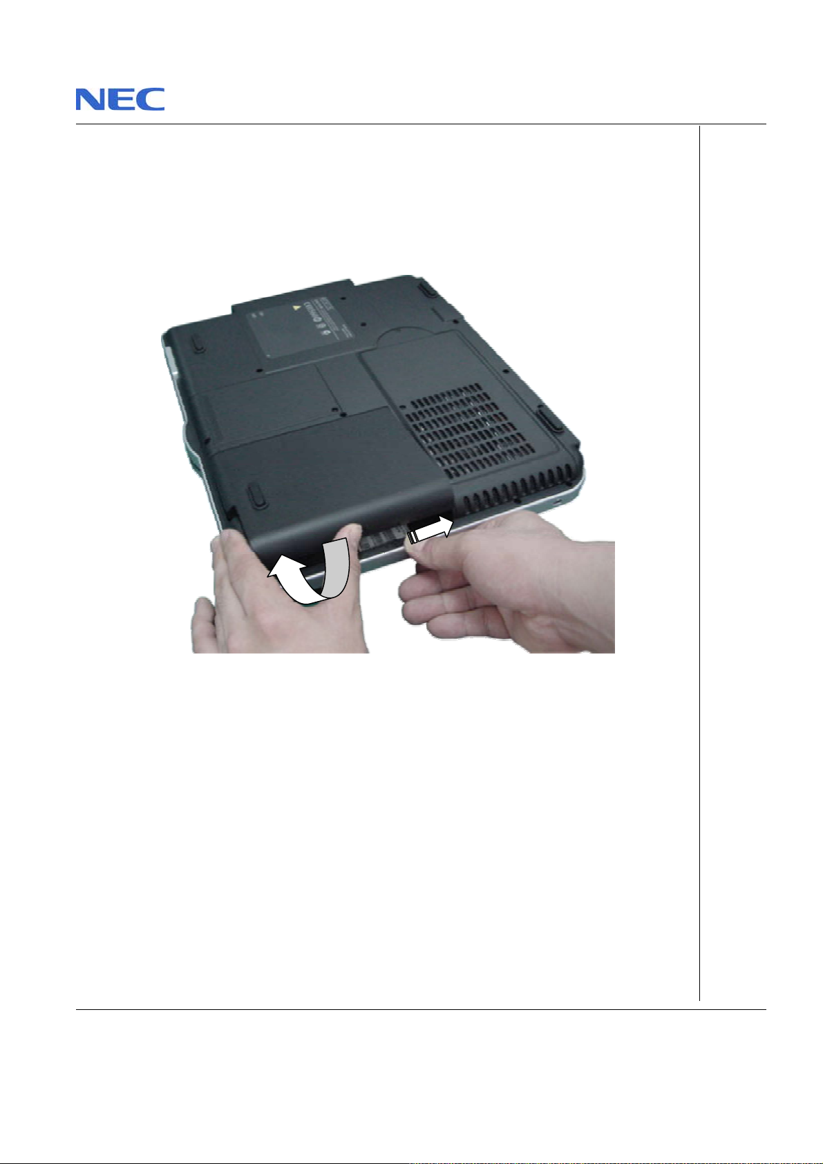
3. Unlock the battery an d slide it out of its place as the arrow shows in Fig. 1
Fig. 1 Removing the battery
NEC Versa M400/PB Easy N ot eM 5 M 7 Disassembly Manual
Page 5
Page 6
Removing the Hard Disk Drive
To remove the hard di sk driv e, fir st remove th e batt ery (see Removing the Battery), then perform
the foll owing steps:
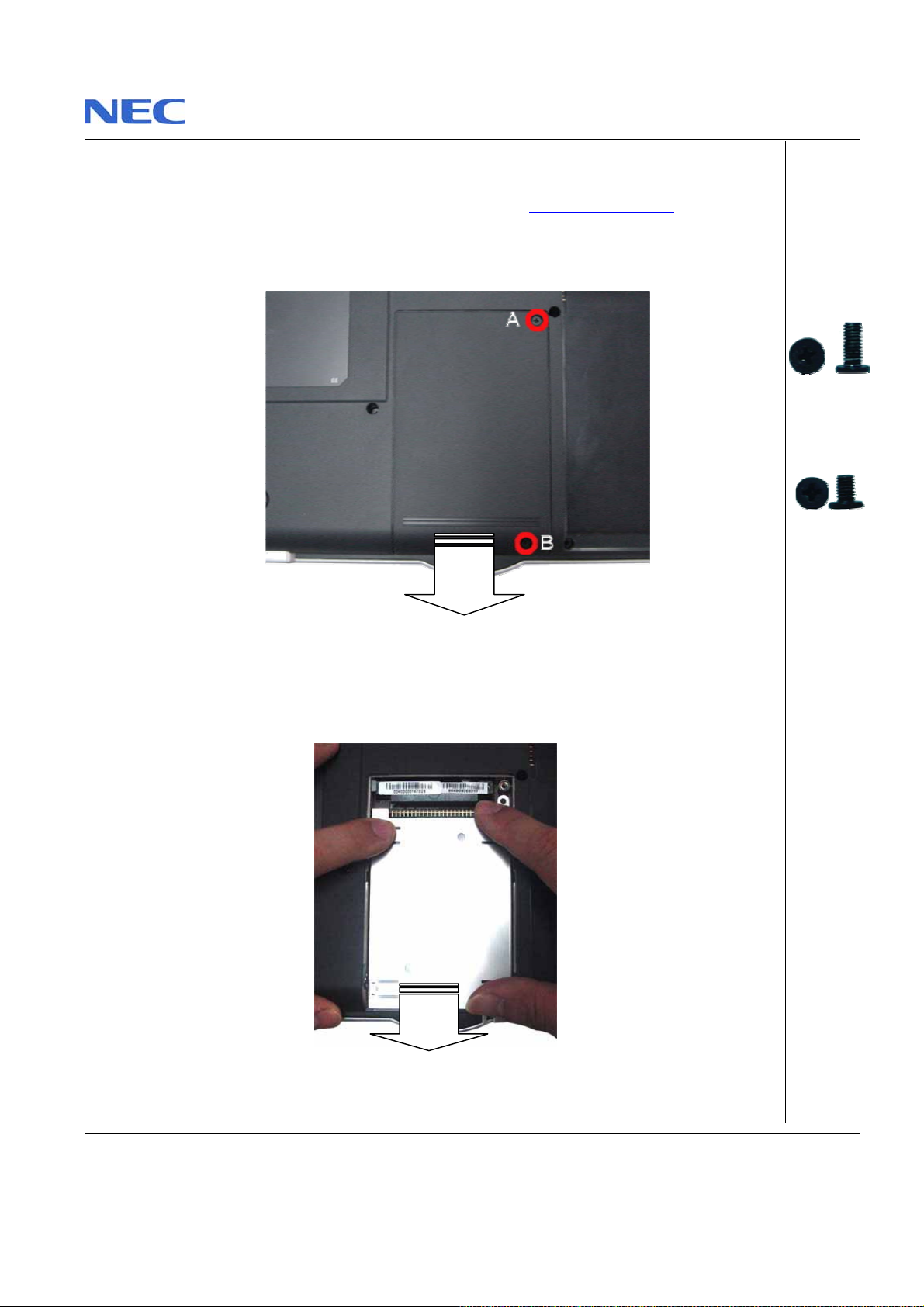
1. Remove the s crews as shown in Fig. 2
A = M2.5x 7
Black
Fig . 2 Re mo v ing t h e Hard disk d r i ve cov e r
2. Disconnect the HDD as sh own in Fig. 3
Fig. 3 Disconne cti ng the hard di sk dri ve
NEC Versa M400/PB Easy N ot eM 5 M 7 Disassembly Manual
B = M2.5x5
Black
Page 6
Page 7
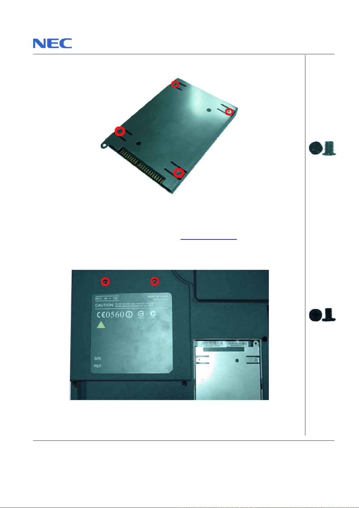
3. Unscrew the four screws on both si des of the hard di sk drive as shown in Fig. 4
Fig. 4 Unscrewi ng th e hard disk dri v e shield screws
Removing the Optical Disk Drive
To remove the ODD, first remove the battery (see Removing the Batt ery), then the HDD Cover
(see Removing the Hard Disk Dri ve), then perform the following steps:
1. Remove the screws ret aining the opt ical driv e connector as shown in Fig. 5
Fig. 5 Releasing the optical drive
M3x4 Sliver
M2.5x5 Black
NEC Versa M400/PB Easy N ot eM 5 M 7 Disassembly Manual
Page 7
Page 8
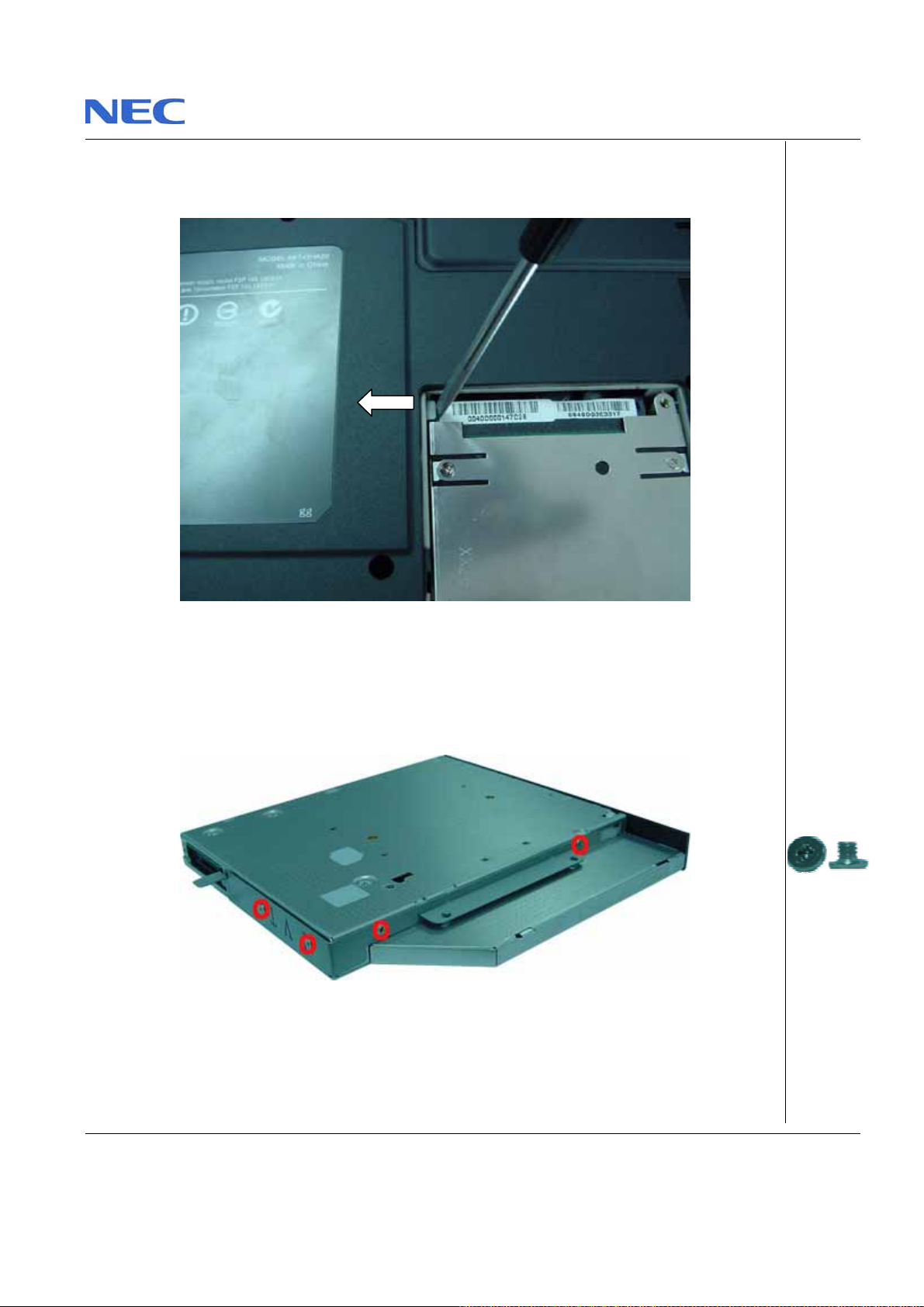
2. Push the metal plate in t he HDD compartment in order to disconnect the optical drive out f rom
the base unit as shown i n F ig. 6
Fig. 6 Removing the optical drive
3. Remove the Optical Drive Bracket from the ODD as s hown in Fig. 7
M2x2.5 Silver
Fig . 7 Removing the Optical Drive Bracket
NEC Versa M400/PB Easy N ot eM 5 M 7 Disassembly Manual
Page 8
Page 9
Removing the Keyboard
To remove the Keyboard, first remove t he battery (see Removing the Battery), then perform the
following steps:
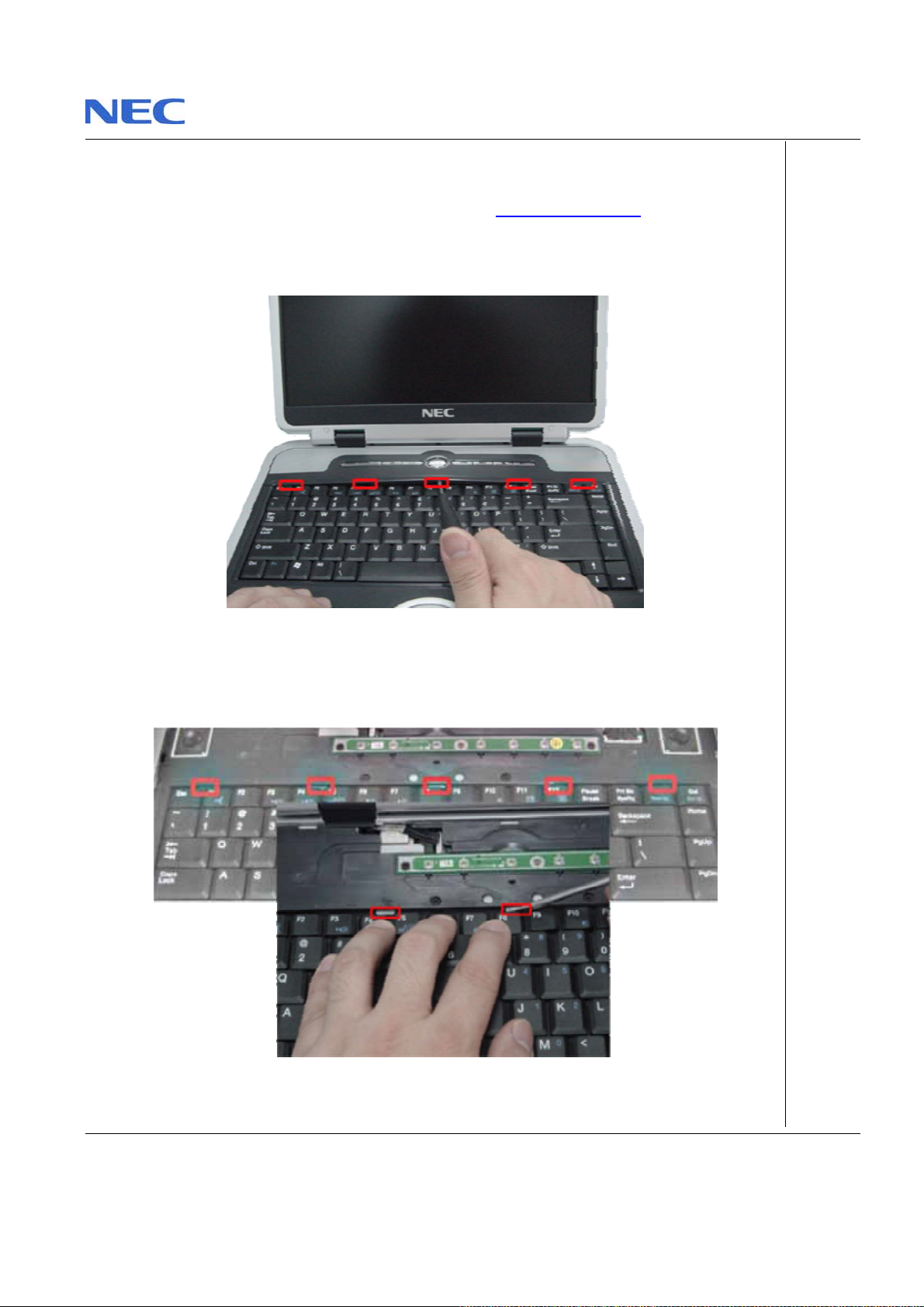
1. Use a flat scr ewdriver to lift up the Keyboard Cov er as shown in Fig. 8
Fig. 8 Removing the Keyb oard Cover
2. Unlock Keyboard as show n in Fig. 9
Fig. 9 Unlock Keyboard
NEC Versa M400/PB Easy N ot eM 5 M 7 Disassembly Manual
Page 9
Page 10

3. Lift up the keyboard and disconnect it from the system as shown in Fig. 10
Fig. 10 Removing the keyboard flat cable
Removing th e Memory Module
To remove the Memory Module, f irst remov e the Battery (see Remo ving the Battery), remove the
Keyboard (see Remo ving the Keyboard
1. Release the screws retaining th e memory module slot cover.
) then perform the fo l l owing steps:
M2x2.5 Si l ver
Fig. 11 Removing the screw retaining the memory module slot cover
NEC Versa M400/PB Easy N ot eM 5 M 7 Disassembly Manual
Page 10
Page 11

2. Unclip t he memory module as shown in Fig. 12
Fig. 12 Re mov ing th e me mo r y modu l e
3. Remove the memory mo dul e from its s lot and put it aside.
NEC Versa M400/PB Easy N ot eM 5 M 7 Disassembly Manual
Page 11
Page 12

Removing the LCD Module
To remove the LCD Module, first remov e the Battery (see Removing the Battery), re mov e the
Keyboard (see Remo ving the Keyboard
1. Disconnect the LCD connectors as s hown in Fig. 13
Fig. 13 Disc onn ecti ng LCD Conn e ctor
2. Carefully pull the LC D ca ble upward to release both Hinge Cover as shown i n F ig. 14
Fig. 14 Removing the Hinge Covers
NEC Versa M400/PB Easy N ot eM 5 M 7 Disassembly Manual
) then perform the fo l l owing steps:
Page 12
Page 13

3. Release the screws on the LCD Hing es as shown in Fig. 15
Fig. 15 Releasi n g the LCD Hinges
4. Caref u l ly li ft up t he L CD modul e a n d p lac e i t i n a s af e pl ace.
M3x6 Sliver
NEC Versa M400/PB Easy N ot eM 5 M 7 Disassembly Manual
Page 13
Page 14

Removing the 15" LCD Panel
To remove the LCD pane l, fi r st remove the LCD modu le (se e Removing the LCD Module), t hen
perform the followi ng steps:
1. Use a pin to remove the rubber covers on the LC D module as s hown in Fig. 16 & Fig. 17
Fig. 16 Removing the rubber covers on the LCD Module
2. Unscrew a l l sc rews show n in Fig. 17
Fig. 17 Screws o n the LCD Module
NEC Versa M400/PB Easy N ot eM 5 M 7 Disassembly Manual
A = M2x4 Black
B = M2.5x7
Black
Page 14
Page 15

3. Release the LCD Bezel from the side carefully and put it aside as shown in Fig. 18
Fig. 18 Removing the LCD Bezel
Note: For the 15” LC D Models, you need to open up the LCD Bezel from either l e f t or right side of
LCD module.
4. Unscrew a l l sc rews encircled in Fig. 19
Fig. 19 Removing the LCD panel screws
NEC Versa M400/PB Easy N ot eM 5 M 7 Disassembly Manual
A = M2.5x 7
Black
B = M2x4 Black
Page 15
Page 16

5. Remove the S ide Rubber Covers at the side of the LCD. Release all four screw s.
Fig. 20 Remov e Side Rubber Cover
6. Carefully l ift up LCD pan el together w i th the Invert er board and disconnect the power cable
from the Inverter board. Disconnect the inverter connect or remaining on the left side of the
invert er board. Put a side the inverter board.
7. Remove the screws on both sides of the LCD panel in order to release the LCD hinges as
shown i n Fi g. 21
M2x 4 Bl ack
M2x3.5 Black
Fig. 21 Removing the LCD Pan el hinges
NEC Versa M400/PB Easy N ot eM 5 M 7 Disassembly Manual
Page 16
Page 17

Removing the 15.4" LCD Panel
To remove the LCD pane l, fi r st remove the LCD modu le (se e Removing the LCD Module), t hen
perform the followi ng steps:
1. Use a pin to the remove rubber covers on the LCD mo dule as shown in Fig. 22
Fig. 22 Removing the rubber covers on the LCD Module
2. Unscrew a l l sc rews as shown in Fig. 23
A = M2.5x 7
Black
B = M2x4 Black
Fig. 23 Screws o n the LCD Module
NEC Versa M400/PB Easy N ot eM 5 M 7 Disassembly Manual
Page 17
Page 18

3. Release the LCD Bezel from the side carefully and put it aside as shown in Fig. 24
Fig. 24 Removing the LCD Bezel
Note: For the 15.4” LCD Models, you need to o pen up the LCD Bezel from eit her left or right side
of LCD module.
4. Unscrew a l l sc rews encircled in Fig. 25
Fig. 25 Removing the LCD panel screws
NEC Versa M400/PB Easy N ot eM 5 M 7 Disassembly Manual
A = M2x4.5
Sliver
B = M2x4 Black
C = M2.5x 7
Black
Page 18
Page 19

5. Remove the S ide Rubber Covers at the side of the LCD. Release al l two screws.
Fig. 26 Re movi n g t he Side Rubb er C o v e rs
6. Carefully l ift up the LCD panel together with t he Inverter board and disconnect the power
cable from the Inverter board. Disconnect t he i n verter connector remaining on the left side of
the inv ert er board. Put a side the i nverter board.
7. Remove the screws on both sides of the LCD panel in order to rel ease the LC D hinges as
shown i n Fi g. 27
M2x 4 Bl ack
Fig. 27 Removing the LCD Pan el hinges
8. Release the speakers at both sides o f the LCD back cover as shown in Fig. 28
Fig. 28 Removing the Spea kers
NEC Versa M400/PB Easy N ot eM 5 M 7 Disassembly Manual
M2x3.5 Black
M2x3.5 Black
Page 19
Page 20

Removing the CPU
To remove the CPU, first remove t he battery (see Removing the Battery), then perfor m the
following steps:
1. Remove the scre w retaining the CPU Cover as shown in Fig. 29
Fig. 29 CPU Cover
2. Release a l l screws on the heat sink, di sconnect the Fan connect or and caref ully remove t he
heat sink as shown in Fig. 30
M2.5x5 Black
M3x21 Silver
Fig. 30 Removing the heat sink
NEC Versa M400/PB Easy N ot eM 5 M 7 Disassembly Manual
Page 20
Page 21

3. Unlock the CPU and carefully rem ove it fro m the CPU socket as shown in Fig. 31 Fig. 31
Fig. 31 Unlocking the CPU
NEC Versa M400/PB Easy N ot eM 5 M 7 Disassembly Manual
Page 21
Page 22

Removing the Bottom Cover
To remove the Bott om Cover, first remove the key board (see Removing the keyboard), remove
the CPU (see Removing the CPU
then perf orm the follow ing steps:
1. Remove the s crews maintaining the Quick Key Boar d, lift it up and place it in safe location.
), remove the LCD module (see Removing the LCD Module)
Fig. 32 Removi ng the Qui ck Key Board
2. Release a l l screws as show n in Fig. 33
Fig. 33 Removi ng the top cov er scr ews
NEC Versa M400/PB Easy N ot eM 5 M 7 Disassembly Manual
M2.5x3.5 Black
M2.5x3.5 Black
Page 22
Page 23

3. Flip over the unit and remove the s cr ews as shown i n F ig. 34
Fig. 34 Removing screws on bottom of the system
4. Remove the screws on the rear side of the system.
A = M2.5x 5
Black
B = M2.5x7
Black
A = M2.5x3.5
Black
Fig. 35 Rear side of the s yst em
5. Carefully l ift up the bottom cover, release it and put it aside.
Fig. 36 Removing the Bottom Cover
NEC Versa M400/PB Easy N ot eM 5 M 7 Disassembly Manual
B = M2.5x5
Black
C = M5x10
Sliver
Page 23
Page 24

Note: When assembling bottom cover, please make sure that the bottom cover is properly insert
int o top cover espe cially the corner near to rear of the system.
NEC Versa M400/PB Easy N ot eM 5 M 7 Disassembly Manual
Page 24
Page 25

Removing the Main Board
To remove the mai n board, first remove the Bottom Cover (See Rem oving the Bottom Cover) then
perform the followi ng steps:
1. Disconnect the LED Boar d as shown in Fig. 37
Fi g. 37 Di sconn ecti ng mai n board and LE D boar d
2. Carefully separate the Main Boar d assembly fro m the top cover as shown i n Fig. 38
Fig. 38 Lifti ng up the Main Board assembly
NEC Versa M400/PB Easy N ot eM 5 M 7 Disassembly Manual
Page 25
Page 26

3. Disconnect all connector from the Main Board and remove the screw hol ding the heat plate as
shown in Erro r! Reference source not fou n d.
Fig. 39 Separat ing Mai n board
Removing the MDC Modem Module
To remove the MDC Modem Modul e, first re move the Main Board (see Removing the Main
Board), then perform the following steps:
1. Remove the s crews retaining the MD C Modem as shown in Fig. 40
M2.5x7 Black
Fig. 40 Removing the screws retaining the MDC Modem
2. Careful l y lift up the MDC m odem module.
3. Disconnect the cable at tached to the MDC modem an d put the modem aside.
Note: The location of the MDC mod em in the Versa M400/EasyN ot e M5 is diff erent than the one
in the EasyNote M7. On the M7 the MDC modem is located under the touch pad. On the M5 the
MDC modem is next to the PCMCIA slot.
NEC Versa M400/PB Easy N ot eM 5 M 7 Disassembly Manual
M2x4.5 Black
Page 26
Page 27

Removing the WLAN Module
To remove the WLAN M odule on Versa E400/EasyNote M5, first remove the Main B oard (see
Removi ng the Main Boar d
To remove the WLAN M odule on EasyNote M7, first remove the Keyboar d (see Remo ving the
Keyboard), then perform the following steps:
1. Disconnect the WLA N ante nna conne cti on on the WLA N Modul e then unc lip i t as shown in
Fi g. 41
2. Carefully lift up the WLAN modul e and put it aside.
Note: The locat i on of the WLAN mod ule i n the Versa M400/ Easy N ote M5 i s differe nt than the one
in theEasyNoteM7. On the M7 the WLAN module is located under the keyboard. On the M5 the
WLAN module is next to the PCMCIA slot.
NEC Versa M400/PB Easy N ot eM 5 M 7 Disassembly Manual
), then perform the following steps:
Fig. 41 Removing the WLAN Module
Page 27
Page 28

Removing the Touch Pad
To remove the touch pad, firs t r emove the Main Board (see Removing the Main Board), then
perform the followi ng steps:
1. Unscrew t he screws on the Touch Pa d ass embly as shown in Fig. 42 and remove the t ouch
pad assembly fro m the Top cov er.
Fig. 42 Touch Pad
Removing the Speaker Assembly
To remove the Speaker assembly, first remove the Main Board (see Removing the Main Board),
then perf orm the follow ing steps:
1. Remove the screws holdi ng Au di o Board hold er as sho wn in Fig. 43
Fig. 43 Screw at Audio Board Hol der
2. Carefully remov e the Spea ker assembly from bott o m base and plac e it aside.
M2x 3 Bl ack
M2x3.5 Black
NEC Versa M400/PB Easy N ot eM 5 M 7 Disassembly Manual
Page 28
Page 29

DIP Swit ch Setting
No DIP Switch settings are avai la bl e for the Versa M400/EasyNote M5 and EasyNote M7.
Screws
M2x3.5 Black M2x3 Black M2x4.5 Black M2.5x7 Black
M2.5x5 Black M2.5x3.5 Black M2x4 Black M3x21 Silver
M2x 2 . 5 Silver M 2 x4.5 Sl iver M3x4 Sli ver M5x10 Sil ve r
NEC Versa M400/PB Easy N ot eM 5 M 7 Disassembly Manual
Page 29
Page 30

Notice
The infor mati on i n this guide is subject to chang e wit hout noti ce.
This guide contains information protected by copyright. No part of this guide may be photoco pied or repro duced in
any form or by any means without prior writ ten consent from NEC Computers International BV.
NEC COMPUTERS INTERNATIONAL BV SHALL NOT BE LIABLE FOR TECHNICAL OR EDITORIAL ERRORS
OR OMISSIONS CONTAINED HEREIN; NO R FOR I NCIDENTAL OR CONSEQUENTIAL DAMAGES RESULTING
FROM THE FURNISHING, PERFORMANCE, OR USE OF THIS MATERIAL.
Copyright © 2003 NEC Computers International BV. All rights reserved.
NEC is a trademark of NEC Comput ers International BV.
The names of actua l compani es a nd product s ment i one d herei n may be trademar ks and/ or regi s tere d tradem arks
of their respectiv e owners.
Versa M 400/PB Ea syNote M5 M7 Disassembly Manua l
Author: Allen Koay
First Edition: August 2003
Document P art Number:
Ver s ion : 1.2
NECCM
A divi sion of NEC Computers International BV
NEC Versa M400/PB Easy N ot eM 5 M 7 Disassembly Manual
Page 30
 Loading...