

Page 1

TJ-70
MINI THERMOJET HANDPIECE
PACE P/N 7023-0002
OPERATION & MAINTENANCE
INSTRUCTIONS
MANUAL NUMBER 5050-0349
REV . A
For any questions regarding the following instructions, contact your local authorized
P ACE dealer or contact P ACE directly at:
Telephone (301) 490-9860, Fax (301) 604-9215
PACE Incorporated
9893 Brewers Court
Laurel MD 20723-1990
1
Page 2

PACE Incorporated retains the right to make changes to specifications contained
herein at any time, without notice.
Contact your local authorized P ACE Distributor or PACE Incorporated to obtain the
latest specifications.
The following are registered trademarks and/or servicemarks of P ACE Incorporated,
Laurel Maryland U.S.A. and may only be used to identify genuine P ACE products or
services:
AdapTip, Arm-Evac, Cir-Kit, ComForm I, ConducTweez, CRAFT,
Dual Path, Flo-D-Sodr, FuseSet, HandiPik, HotSpot, LapFlo, MBT,
Micro Portable, MicroChine, MiniChine, Pacenter, PACE, Ped-A-Vac,
PETS, PIK-V AC, PRC, PRINT , Pro-Evac, ResisT weez, SensaT emp, SMR,
SNAP-VAC, Sodr-X-Tractor, SR-3, SR-4, ST, StripTweez, SwaPlater,
ThermoBand, ThermoJet, ThermoPart, ThermoPik, ThermoTweez, ThermoDrive, Tip-Evac, VisiFilter .
The following are trademarks and/or servicemarks of P ACE Incorporated, Laurel
Maryland U.S.A. and may only be used to identify genuine PACE products or
services:
EKO , Redi-Rak, Mini-Wave, Sodr-P en.
PACE Incorporated has provided training on all of its products since 1958
as well as advanced technology training in all aspects of hand soldering,
rework and repair.
Additional copies of this manual or other P ACE literature may be obtained from:
P ACE Incorporated (301) 490 - 9860
Sales Administration (301) 4983252 Fax
9893 Brewers Court
Laurel MD 20723-1990
©1993 PACE Incorporated, Laurel MD. All rights reserved. Printed in the U.S.A.
2
Page 3

3
This manual details the basic operational guidelines for using the TJ-70 Mini ThermoJet
handpiece. A detailed Operation & Maintenance Manual For Accessories (P/N 5050-
0350) is available from PACE.
CAPABILITIES
The TJ-70 Mini ThermoJet Handpiece provides safe, continuous flow of precision
focused hot air for component installation and SMT land preparation. It is primarily
an installation tool and can be used for hot air installation of most surface mount
components. Its slim-line, pencil grip design and finger actuated control switch
facilitates ease of use and manipulation in tight places. The TJ-70 is a member of the
PACE SensaTemp family of advanced handpieces.
CAUTION
Always return heated handpieces to the appropriate Hot Cubby when not
in actual use. Failure to do so may cause burns to the operator, equipment
or work surfaces, and may be a potential ignition source if combustible
materials are nearby. Always use this handpiece in a well ventilated area
to avoid inhalation of fumes created by solder flux gases.
HANDPIECE SETUP
Connect the handpiece power cable plug to one of the handpiece power receptacles
on your PACE power source. PACE recommends that air handpieces utilize the power
receptacles closest to the SNAP-VAC and Controllable PRESSURE Ports to minimize
cord tangles. Connect an Air Hose to the TJ-70 using the method listed below.
Determine the proper tip to install and install the tip in the method listed under “Tip
Installation”.
NOTE
If using your TJ-70 Mini ThermoJet Handpiece for the first time or if you have
just replaced the heater, we recommend that you follow the “TJ-70 Heater
Burn-in” procedure (Red tag on handpiece) to increase the life expectancy
of the heater and to minimize any smoke and fumes generated by the heater
on its initial power-up.
Page 4
4
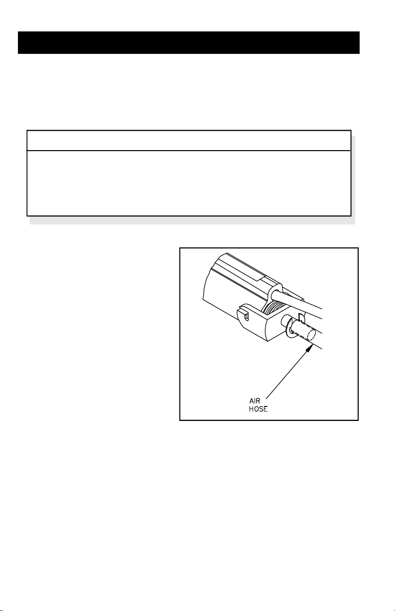
AIR HOSE CONNECTION
The Traditional Method of attaching the Air Hose from the power source is best
suited for use with the TJ-70.
NOTE
Ensure that no Air Hose is connected to the SNAP-VAC Port when using
the TJ-70 handpiece. The TJ-70 Air Hose must be connected to the
Controllable PRESSURE Port. Attachment to both ports simultaneously
will cause a deterioration of performance.
TRADITIONAL CONNECTION
1. Connect the 137cm (54 inch)
length of Air Hose to the metal
tube in the back of the
handpiece.
2. Insert the ridged end of a male
quick connect hose mount
fitting (P/N 1259-0087) into the
free end of the 137cm (54 inch)
length of Air Hose.
3. Secure the Air Hose to the
cable assembly with cable clips (P/N 1321-0085-01).
4. Attach the remaining end of the 137cm (54 inch) length of Air Hose (with
attached male fitting) to the power source Controllable PRESSURE Port.
5. To avoid confusion among handpieces, PACE recommends the use of
colored markers (P/N 6993-0136 Cable Marker Kit) to identify the Air Hose
connected to the handpiece. Attach any two like colored markers, one to
each end of the Mini ThermoJet Air Hose. Any Air Hose attached to
another handpiece should contain markers of another color.
Page 5

5
TIP INSTALLATION
Tip selection is very important. Referring to the list of Available Tips (Table III),
select the appropriate tip for your application.
The following instructions are for tip installation only. If a tip is currently installed in
the handpiece, follow the “Tip Removal” procedure prior to the installation of a new
tip.
1. Select the proper tip for your
application. Refer to Table III.
2. Holding the handpiece in a
horizontal position, the selected
tip should be fully inserted until
the tip seats itself against the
heating element.
NOTE
Holding the handpiece tip down may cause the tip to fall out before the set
screw has been tightened.
3. Orient the tip with the finger switch on the handpiece as desired for
optimum use.
4. Using the tip tool or small screwdriver, tighten heater set screw to secure.
Do not over tighten.
5. Apply power to the handpiece and set the operating temperature to 482°C
(900°F). After a short period (1-2 minutes) recheck the tip set screw to
ensure that it remains snug. On very light boards, you may need to lower
the temperature to protect the board from damage.
Page 6

6
TIP PREPARATION
TJ-70 tips are not tinnable and require little maintenance. Keep tips clean and free of
any foreign particles. Insure that all tip air jets are kept clean to prevent air flow
obstruction.
TIP REMOVAL
NOTE
To avoid tip damage, the Mini ThermoJet handpiece heater must be at a
temperature of at least 177°C (350°F) before attempting to remove an
installed tip. After removal, always place the hot tip in a tip holder or on a
metal surface to prevent burns or scorches. Hold the handpiece with the
heater body pointing up to prevent injury to personnel when cleaning a hot
handpiece. Dispose of any loose debris properly. The debris is hot.
1. Loosen the heater assembly set screw.
2. Remove the tip using a tip tool or needle nose pliers.
3. Clean the heater bore to remove any foreign particles (i.e., flux) using the
3/16 inch diameter wire brush. Do not push the brush more than 0.64cm
(1/4 inch) into the heater bore to avoid damage to the metal cylinder
installed at the rear of the heater bore.
4. Replace the TJ-70 handpiece in the Hot Cubby.
Page 7

7
TEMPERATURE SETTING
Set the operating tip temperature of the channel powering the TJ-70 handpiece to
482°C (900°F). On very light boards, you may need to lower the temperature to
protect the board from damage.
On MBT 250 and PRC 2000 systems, set the tip temperature offset to 3°C (6°F)
(default setting).
CONTROLLABLE PRESSURE PORT ADJUSTMENT
Air flow is actuated by depressing the finger switch on the handpiece or the optional
foot pedal switch. The rate of air flow can be controlled by the Controllable
PRESSURE Port on the front panel of the power source. Select and install a tip (see
Tip Installation). Experiment using the procedure following to determine an
appropriate level of air flow for your application.
1. Place a tissue paper (or like material) on the surface of your work bench.
NOTE
Insure that no flammable materials are positioned beneath the tissue. A
Controllable PRESSURE Port setting of MIN to 3 is the best for general use.
A setting of MIN to 1 are recommended when installing very small
components such as chip capacitors.
2. With the Controllable PRESSURE Port set at minimum (MIN), press the
finger switch on the handpiece and direct the hot air at the tissue from a
distance of about 0.64cm (1/4 inch).
3. While continuing to depress the finger switch, slowly draw a series of
burn lines on the tissue paper while increasing the Controllable
PRESSURE Port setting slowly with the free hand.
4. Continue to experiment drawing the burn lines. Vary the the speed of
handpiece movement, distance of the tip from the tissue and the
Controllable PRESSURE Port setting until you become comfortable with
handpiece use.
Page 8

8
COMPONENT INSTALLATION
Perform the following procedure to install the component.
NOTE
To prevent damage to the component during placement, PACE recommends
handling the component with a vacuum pick device such as the PACE PikVac or HandiPik. Always place the hot tip in a tip holder or on a metal
surface to prevent burns or scorches.
1. Carefully clean the replacement component leads (or terminations) and
substrate land pattern area using an approved solvent. Insure that no
leads or terminations become deformed during the process.
2. Apply solder paste to the lands.
3. Properly orient the replacement component with respect to the land
pattern; centering the component leads (or terminations) with their
corresponding lands.
4. Gently place the component
onto the land pattern taking
care to maintain proper lead to
land alignment.
5. Apply a very small downward
pressure to the component
body; forcing the leads (or
terminations) gently into the
solder paste.
Page 9

9
6. Bring the tip of the handpiece to a distance of 2.5cm (1 inch) from the
component leads (or terminations). Press the finger switch to begin air
flow. Direct the air flow to one side of the component and begin to heat
the leads and lands in a side to side sweeping motion across the lead (or
termination) or along the length of one row of leads. After evaporation of
solder paste flux is observed, move the tip closer to the component with a
continuous air flow until complete solder reflow occurs.
7. Continue to heat the lead/land contact area(s) until formation of shiny
solder fillets is observed. Fillets on chip components and SOICs will be
slightly concave on each lead; fillets on extended lead devices should
cover the sides, toe and heel of each lead.
8. Release the finger switch to stop air flow.
9. Repeat the above procedure for leads on all sides of the component.
10. Clean and inspect per your company specifications.
NOTE
If this process has not been successful, preheating of the PC Assembly
and/or adjustment of the Controllable PRESSURE Port may be required.
SPECIAL APPLICATIONS
If you require assistance in the use of this handpiece or require assistance with a
special application, contact PACE Applications Engineering at:
Tel: (301) 490 - 9860
Fax: (301) 604 - 9215
Page 10

10
CORRECTIVE MAINTENANCE
Your TJ-70 requires no special maintenance other than being kept clean. The
heater bore and the heater assembly set screw which secures the tip must be
kept free of oxidation and debris in order to maintain the proper tip to ground
resistance. Periodically inspect the cable, connector and handpiece itself for
evidence of physical damage. Do not use a handpiece with a damaged cable.
Refer to Table I (TJ-70 Heater Assembly Checkout Procedures) and the
Connector Plug illustration below for information on troubleshooting most
handpiece problems. Table II lists the common handpiece parts.
SYMPTOM CHECKOUT PROCEDURE CAUSE SOLUTION
No heat Check resistance - Pin 2 to Pin 5.
If the resistance is greater than
Handpiece
overheating
No Ground
on Tip
7 ohms -
Check resistance - Pin 3 to Pin 6.
If circuit reads open -
Check resistance - Pin 3 to Pin 6.
Resistance should be 110 ohms. If
circuit reads less than 105 ohms -
Check resistance - Pin 4 to a NEW
Tip. Resistance should be less than
2 ohms. If not -
Open Heater
Open Sensor
Shorted
Sensor
Oxidation
buildup in
Heater Bore
Defective
Heater
TABLE I. TJ-70 HEATER ASSEMBLY CHECKOUT PROCEDURES
Replace
Heater
Assembly
Replace
Heater
Assembly
Replace
Heater
Assembly
Clean Heater
Bore using
appropriate
wire brush
Replace
Heater
Assembly
Page 11

11
CONNECTOR PLUG WIRING
PART
DESCRIPTION
NUMBER
HEATER ASSEMBLY 6010-0084-P1
CORD/SWITCH ASSEMBLY 6993-0134
HEATER SET SCREW 1348-0547
WIRE BRUSH, 3/16" DIAMETER 1127-0014
Handpiece tips listed following page - - - - - - - -
TABLE II. TJ-70 REPLACEMENT PARTS
Page 12

12
TIP DESCRIPTION TIP SIZE
PART
NUMBER
Small, Straight, Single
Jet Tip
Small, Curved Single
Jet Tip
SOT/Chip Component
Tip (dual-jet)
SOIC Tip (dual-jet) A = 0.17" (4.32mm) 1121-0330
A
SOICL Tip (dual-jet) A = 0.37" (9.40mm) 1121-0331
Flat End Tip
A
B
TABLE III. TJ-70 AVAILABLE TIPS
--------- 1121-0366
--------- 1121-0338
A = 0.14" (3.56mm) 1121-0329
A = 0.28" (7.11mm)
B = 0.074" (1.88mm)
A = 0.24" (6.10mm)
B = 0.074" (1.88mm)
1121-0365
1121-0371
 Loading...