

Page 1

Flo Pump Assembly
(for PACE ThermoFlo power sources)
P/N 1336-0035-P1
Installation Instructions
Manual Number 5050-0433
Rev . A
For any questions regarding these instructions, contact the PACE Service
Department directly at:
Telephone (888) 535-PACE, Fax (301) 483-7030
P ACE Incorporated
9893 Brewers Court
Laurel MD 20723-1990
1
Page 2
To replace the Flo Pump Assembly, perform the following procedure step by step,
in sequence using the accompanying illustrations as a guide.
CAUTION
POTENTIAL SHOCK HAZARD - Disassembly of the ThermoFlo power
source exposes line voltage parts. Replacement of the Flo Pump Assembly
must be performed by qualified service personnel only . Service personnel
must insure that the AC power cord is disconnected prior to disassembly.
Contact the PACE Service Department for assistance at tel. 1-888-535PACE, FAX 1-301-483-7030.
1. Place the unit on a suitable work surface with the front of the power
source facing forward.
2. Disconnect the AC power cable from the unit (if present).
NOTE
Use all ESD control precautions when servicing the PACE ThermoFlo
system. The power source contains assemblies utilizing static sensitiv e
components.
3. Remove the 10 Front Panel mounting screws.
4. Pull the Front Panel forward.
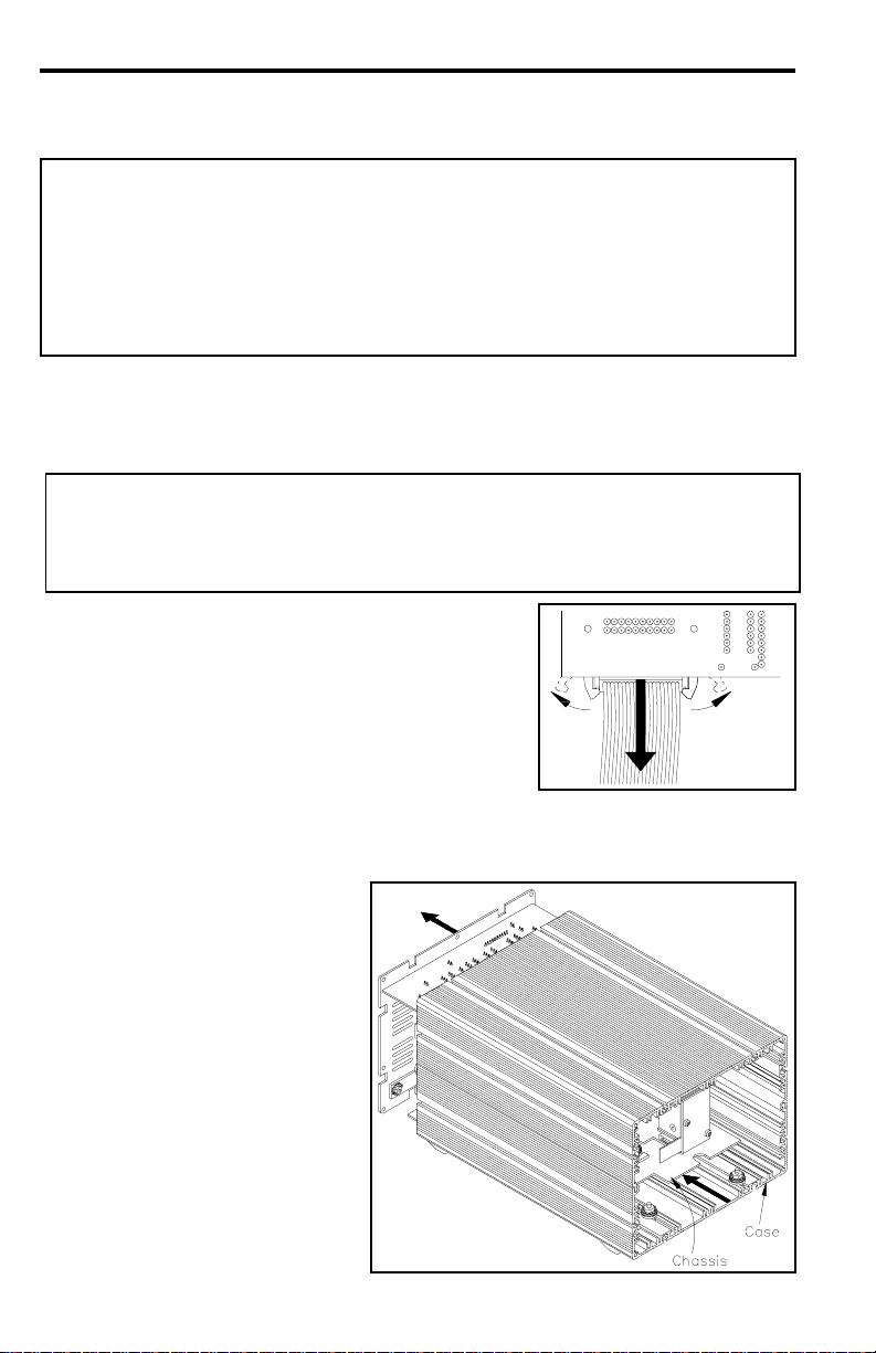
5. Disconnect the ribbon cable from the Front
Panel by pulling the 2 plastic locking tabs
away from the ribbon cable (see illustration)
then pulling the ribbon cable out of the Front
Panel connector. Set the Front Panel aside.
6. Reposition the unit with the rear of the power source facing forward.
7. Remove the 8 Rear Panel
mounting screws.
8. Gently pull the Rear Panel
away from the power
source. Attached to the
Rear Panel are the main
PCB and the Inner Chassis.
Pull these parts completely
out of the power source
case. Set the power source
Case aside.
2
Page 3
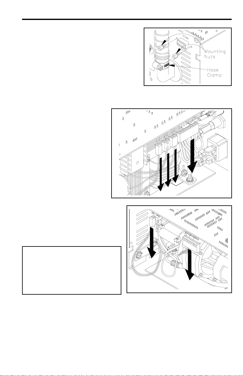
9. The COM Port is located on the upper
right portion of the Rear Panel.
Remove the two (2) Mounting Nuts
located on either side of the COM Port.
10. Position the Chassis as shown with the Flo Pump Assembly facing
forward.
11. Disconnect the four (4)
connectors shown from the
Main PCB. Make note of
the location of each
connector (the Flo Pump
harness plug should be
marked "P10").
12. Disconnect two (2)
connectors shown from the
Main PCB.
CAUTION
The larger of these two
connectors has very fine wires
attached. Handle this connector
with care to prevent any
damage to these wires.
13. Pull the Main PCB forward to release pins on PCB plug from the
connector on the HV Board. Set Main PCB aside.
3
Page 4

14. Remove the three (3) Hex Nuts and Washers from the Flo Pump
Assembly.
15. Make a note of the location of the Vacuum Hose attached to the Flo
Pump Assembly. Remove the Vacuum Hose by gently pulling and
twisting the hose.
16. Pull the Flo Pump Assembly up and off of its three (3) mounting studs.
17. There are three (3) Blue grommets (with metal sleeves) on the Flo Pump
Assembly mounting bracket. Remove each of the grommets and install
in position on the replacement Flo Pump Assembly. Set the old Flo
Pump Assembly aside.
18. Push the Flo Pump Assembly down, sliding the three (3) Blue grommets
(with metal sleeves) over the three (3) mounting studs on the Chassis
plate.
NOTE
Insure that wires are not trapped under the Flo Pump Assembly mounting
bracket.
4
Page 5

19. Install the Vacuum Hose removed in step 15 onto the Flo Pump
Assembly mounting bracket.
NOTE
Insure that the small Vacuum Air Hose is installed in the proper location
(at port marked with arrow pointed in) on the Flo Pump.
20. The Vacuum Air Hose is routed between the Flo Pump Assembly and the
Rear Panel. Check to insure that there are no kinks in this length of
hose or in the smaller air hose it connects to near the Rear Panel..
21. Secure the Flo Pump Assembly in position by installing the three (3)
Hex Nuts and Washers removed in step 14.
22. Position the Main PCB as shown over
the Chassis and with the ribbon cable
facing forward.
23. Align the COM Port receptacle at the
rear of the Main PCB with its rear panel
cutout
24. There is a ten (10) pin plug mounted at
the rear of the Main PCB. Carefully
insert these pins into the matching 10
pin connector on the HV Board.
NOTE
Insure that the plug pins are lined up correctly with the connector
receptacle. The system will not operate if this connection is incorrect.
25. Install the two (2) Mounting Nuts
removed in step 9 on either side of
the COM Port.
5
Page 6

26. Install the 6 connectors
removed in steps 11 &
12. Insure that each
connector is pushed
fully onto its PCB
connection. Insure that
the connector marked
"P10" is plugged into
the proper location.
Refer to illustration
27. Slide the Chassis into the rear of the Case with the Main PCB entering
the Case as shown in the illustration below. Located at the front, inside
of the Case are two (2) mounting studs with Blue grommets. The two
(2) slots at the front of the chassis plate must slide into the slots in the
two (2) Blue grommets.
NOTE
Wire harnesses are located along the edges of the Chassis. Insure that
these wires do not get caught or pinched against the edges of the Case
or the rear panel as the Chassis slides in.
VIEWED FROM REAR
28. Install the 8 Rear Panel mounting screws removed in step 7.
29. Position the power source facing forward.
30. Connect the ribbon cable (removed in step 5) to the Front Panel
Connector; the two (2) plastic locking tabs will automatically lock the
cable in position when it is fully seated in the connector.
31. Install the 10 Front Panel mounting screws removed in step 3.
6
VIEWED FROM FRONT
Page 7

PACE Incorporated retains the right to make changes to specifications contained
herein at any time, without notice.
Contact your local authorized PACE Distributor or PACE Incorporated to obtain the
latest specifications.
The following are registered trademarks and/or servicemarks of PACE
Incorporated, Laurel Maryland U.S.A. and may only be used to identify genuine
PACE products or services:
AdapTip, Arm-Evac, Cir-Kit, ComForm I, ConducTweez, CRAFT,
Dual Path, Flo-D-Sodr, FuseSet, HandiPik, HotSpot, LapFlo, MBT,
Micro Portable, MicroChine, MiniChine, Mini-Wave, PACE, Pacenter,
Ped-A-Vac, PETS, Pik-Vac, PRC, Prep-Set, Pro-Evac, Redi-Rak,
ResisTweez, SensaTemp, Snap-Vac, Sodr-Pen, Sodr-X-Tractor, SR-3,
SR-4, ST, StripTweez, SwaPlater, ThermoBond, Thermo-Drive, ThermoJet,
ThermoPart, ThermoPik, ThermoT weez, Tip-Evac,Ventur-Evac VisiFilter.
The following are trademarks and/or servicemarks of PACE Incorporated, Laurel
Maryland U.S.A. and may only be used to identify genuine PACE products or
services:
Heat Wave, Pik-Tip, Pulse Plate, Sodrtek, ThermoFlo, Toolnet.
Since 1958, PACE Incorporated has provided
advanced technology training in all aspects of hand
soldering, rework and repair.
Additional copies of this manual or other PACE literature may be obtained from:
PACE Incorporated (301) 490 - 9860
Sales Administration (301) 498 - 3252 Fax
9893 Brewers Court
Laurel MD 20723-1990
© 1998 PACE Incorporated, Laurel MD. All rights reserved. Printed in the U.S.A.
7
 Loading...