

Page 1

TF 2000
BGA/CSP Rework System
MANUAL NO. 5050-0482
REV. C
Page 1 of 67
Page 2

TABLE OF CONTENTS
Safety................................................................................................................... 4
Introduction .......................................................................................................... 5
Packing Contents................................................................................................. 5
Features............................................................................................................... 7
Set-Up................................................................................................................ 10
Operation ........................................................................................................... 13
Before Operating ..................................................................................... 13
General Operating Procedure ................................................................. 13
Explanation of Each Operation........................................................................... 17
Placing PCB into Board Holder ............................................................... 17
Component Alignment and Placement .................................................... 17
Component Reflow.................................................................................. 19
Adjusting Airflow...................................................................................... 20
Component Removal............................................................................... 20
Selecting a Profile .............................................................................................. 21
Creating and Saving Profiles.............................................................................. 21
PC Software....................................................................................................... 24
Setup Tab................................................................................................ 25
Optics Tab Alignment View ..................................................................... 27
Print/Review ........................................................................................... 29
Operation Tab ......................................................................................... 30
Process Control/Validation................................................................. 31
Profile Development Tab......................................................................... 33
General Information ........................................................................... 34
Profile Creation .................................................................................. 36
Maintenance....................................................................................................... 39
Cleaning the Blower Filter ....................................................................... 39
Replacing the Top Heater........................................................................ 39
Alignment and Calibration .................................................................................. 41
Page 2 of 67
Page 3

PCB to Optics.......................................................................................... 41
Sliding Shaft Holder (Indexing)................................................................ 42
Vacuum Nozzle Planarity ........................................................................ 33
Reflow Head Planarity............................................................................. 44
Reflow Head – “Y” Directional Adjustment .............................................. 46
General Troubleshooting.................................................................................... 47
Initial Operation Flow Chart..................................................................... 48
Nozzle Operation Flow Chart .................................................................. 49
Vacuum Pick Operation Flow Chart......................................................... 49
General Troubleshooting Table ............................................................... 51
TF 2000 L/LE Model Differences........................................................................ 52
Installing the Board Holder ...................................................................... 52
Bottom-Side Heaters ............................................................................... 53
Sliding Shaft Holder Indexing .................................................................. 54
Alignment and Calibration Differences .................................................... 55
Specifications..................................................................................................... 56
Instructions for using the Board Supports .......................................................... 58
Accessory Items................................................................................................. 59
Page 3 of 67
Page 4

Safety
The following are safety precautions that personnel must understand and
follow when using or servicing PACE products.
1. POTENTIAL SHOCK HAZARD - Repair procedures on PACE
products should be performed by Qualified Service Personnel only.
Line voltage parts may be exposed when the equipment is
disassembled. Service personnel must avoid contact with these
parts when troubleshooting the product.
2. To prevent personnel injury, adhere to safety guidelines in
accordance with OSHA and other applicable safety standards.
3. Always use PACE systems in a well ventilated area. A fume
extraction system, such as those available from PACE, is highly
recommended to help protect personnel from solder flux fumes.
4. Exercise proper precautions when using chemicals (e.g., solder
paste). Refer to the Material Safety Data Sheet (MSDS) supplied
with each chemical and adhere to all safety precautions
recommended by the manufacturer.
5. The following safety precautions cover use of PACE hot air
systems/hand pieces (e.g., ThermoFlo
®
, ThermoJet®).
a) Be careful when using in places where there are combustible
materials.
b) Do not use in the presence of an explosive atmosphere.
c) A fire may arise if a hot air hand piece is not used with care.
Do not leave the hand piece unattended when in use.
d) The heater assembly housing and any installed nozzle are
hot when the system is being cycled and for a period of time
thereafter. DO NOT touch either the heater assembly
housing, nozzle or direct heated air stream. Severe burns
may result!
Page 4 of 67
Page 5

Introduction:
Thank you for purchasing the TF 2000 BGA/CSP Rework Station. As
electronic devices continue to get smaller, lighter and more compact,
components and printed circuit boards are also becoming smaller and the
amount of available space on PCBs is continually decreasing. In order to
maximize board space, area array devices are growing in popularity. Area
array devices are BGAs, CSPs and “micro-BGAs”, and Flip Chips. These
devices require an optical overlay vision system to ensure proper placement
and high levels of process control during rework to ensure successful
installation. The TF 2000 has been specifically designed to rework these
types of components and can also install and remove a variety of other SMT
devices.
NOTE: This device complies with part 15 of the FCC rules. Operation
is subject to the following two conditions: (1) This device may
not cause harmful interference and (2) This device must accept
any interference received, including interference that may cause
undesired operation.
The TF 2000 also complies with 98/37/EC and 89/336/EEC.
Caution: During normal operation, the top heater, nozzle, bottom-
side-heater(s) and halogen lamps will get hot. Do not
contact them directly as serious injury could occur.
Packing Contents
TF 2000 with Video Monitor
1. TF 2000B, BE, BL, or BLE: 1 each
2. TF 2000R: 1 each
3. TF 2000P: 1 each
4. Video Monitor: 1 each
5. B/C Video Cable: 1 each
6. Hand Held Vacuum Pick for removal: 1 each
7. Suction rubber (spare for #9): 3 each
8. Vacuum nozzle for positioning: 1 each Large, Medium and
Small sizes
9. Hex Wrench Set and Screwdriver: 1 each
10. Top Heater Element (spare): 1 each
11. Halogen Lamp (spare): 2 each
12. TF 2000 Manual: 1 each
13. K-Type ThermoCouple: 2 each
Page 5 of 67
Page 6

TF 2000 with PC
1. TF 2000B, BE, BL, or BLE: 1 each
2. TF 2000R: 1 each
3. TF 2000P: 1 each
4. Computer: 1 each
5. Computer Monitor: 1 each
6. S-Video Cable: 1 each
7. TF 2000 Software Package: Installed on PC
8. Serial Cable: 2 each
9. Hand Held Vacuum Pick for removal: 1 each
10. Suction rubber (spare for #9): 3 each
11. Vacuum nozzle for positioning: 1 each Large, Medium and
Small sizes
12. Hex Wrench Set and Screwdriver: 1 each
13. Top Heater Element (spare): 1 each
14. Halogen Lamp (spare): 2 each
15. TF 2000 Manual: 1 each
16. K-Type ThermoCouple: 2 each
Page 6 of 67
Page 7

Features
1. The TF 2000 System is comprised of three self-contained stations:
The Reflow Station (Model TF 2000R)
The Placement Station (Model TF 2000P), and
The Base/Pre-Heater Station (Models TF 2000B, TF 2000BE, TF
2000BL, or TF 2000BLE)
Each individual station is lightweight and compact, allowing for easy
set-up and portability.
2. Up to 40 reflow profiles can be stored by the TF 2000. Saved profiles
can be recalled at the touch of a button and are displayed on the LCD
display panel.
3. A colored LED indicates each phase of the reflow cycle so the status of
each operation can be easily seen and monitored.
4. The Placement Station can easily handle components up to 70 mm
square. If needed, a split screen function is available through the
optional software package.
5. A highly efficient, 1000-watt topside heater used in conjunction with a
truly unique nozzle design insures the uniformity of the temperature
across the assembly.
6. The ceramic panel bottom side heater with a wide heating area is
incorporated to insure the co-planarity of the PCB, to prevent warping,
and to enhance the reflow of large BGAs.
7. The blower and vacuum pumps are self-contained. No external air
supplies are required.
8. A cooling fan automatically activates at the end of the reflow cycle to
cool the component, PCB, and nozzle.
9. The TF 2000 is versatile, adaptable and ensures repeatable results.
Page 7 of 67
Page 8
A
TF 2000R TF 2000P
G
B
O
C
D
E
N
P
F
H
I
J
L
K
TF 2000B or TF 2000BE
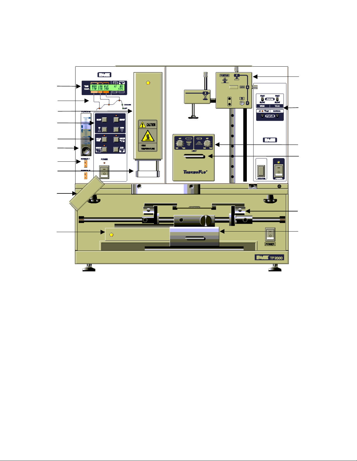
Figure 1: TF 2000 BGA/CSP Rework Station
Features:
Please refer to Figure 1.
A) LCD Display Panel Displays profile variables (time and temperature)
and allows the user to enter/modify profile
parameters.
B) Phase Display Panel Each phase of the reflow cycle is indicated by this
panel.
M
C) Data Entry Panel Used to enter/modify reflow profile parameters and
to save or recall profiles.
Page 8 of 67
Page 9

D) Operations Panel Allows the operator to start/stop a profile cycle,
turn on/off the cooling fan and raise/lower the
reflow head.
E) Air Flow Meter This device is used to control and monitor the
airflow.
F) Cooling Fan The component and the PCB are cooled down by
the cooling fan, which activates automatically,
after the reflow cycle is completed.
G) Alignment Apparatus X, Y, Z and Θ aspects of the component position
are adjusted in relation to the land pattern on the
PCB through this apparatus.
H) Camera Control The zoom and focus functions of the optical
overlay system are controlled at this location. The
Auto-focus feature may also be selected.
I) Light Control The upper (component side) and lower (PCB side)
lights within the optics housing can be adjusted for
intensity (overlay contrast) at this location.
J) Optics Housing Contains the camera and beam splitter. The
housing is retractable and should be kept in the
retracted position when not in use. The lights for
the optics will turn on/off automatically when the
housing is extended.
K) Bottom Side Heater Used to warm the PCB from the underside. It is
an IR type of heating source. The pre-heater
temperature is set in the “PRE-HEAT” display and
will remain on throughout the reflow cycle. When
the cycle enters the reflow phase, the bottom-side
heater temperature will increase by 30ºC to ensure
successful reflow. A power consumption indicator
light is mounted onto the pre-heater to indicate
when it is drawing power.
**NOTE: For TF 2000L/LE models, refer to
Section 10 for model differences.
L) Board Holder The board holder is fully adjustable in both the X
and Y directions. The right side of the holder is
spring loaded to hold the PCB securely. Fine
adjustment in the X direction is achieved by using
the adjustment knob on the Sliding Shaft Holder.
Page 9 of 67
Page 10

M) Sliding Shaft Holder Supports the rail system for the board holder. It is
also used to index the table from the Placement
Position to the Reflow Position using the handle
on the front.
N) Sensor 1 & 2 Inputs The sensor inputs have been designed to use K-
type thermo-couples. Measured temperatures are
displayed on the LCD display, real time, and can
be interfaced to a PC using the TF 2000 Software
(optional) through the serial port on the back of the
TF 2000R.
O) Reflow Head Contains the top-side heater and moves up and
down via an electric motor that is controlled
through the operations panel. A power
consumption indicator light is mounted onto the
front of the reflow head to indicate when it is
drawing power. The reflow head is clutched to
prevent excessive downward force from being
applied.
P) Nozzle The nozzles for the TF 2000 are easily changed.
Several varieties are available. Use caution and
proper hand protection when changing nozzles, as
they will be hot.
**NOTE: For TF2000 L/LE models, refer to Section 10 for a detailed
description of model differences.
Page 10 of 67
Page 11
1 SET-UP
TF 2000 Setup & Connection to Video Monitor
1-1 Place the TF 2000B, TF 2000BE, TF 2000BL, or TF 2000BLE on a
flat and stable bench. Refer to Section 10 for board holder
installation on L/LE models.
1-2 Place the TF 2000R and TF 2000P on the base as indicated in
Figure 1.
1-3 Secure the TF 2000R and TF 2000P by following the directions in
the box containing the base unit. Refer to Figure 1.
1-4 Connect the power cables as indicated in the wiring diagram label
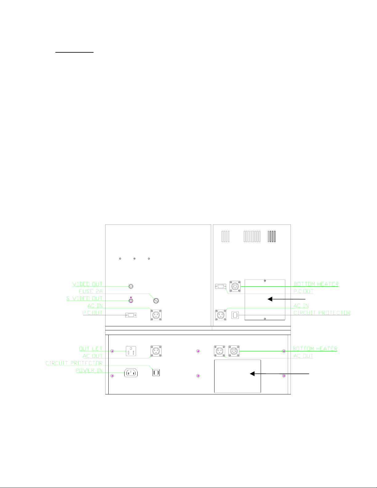
on the back of the units. See Figure 2.
1-5 Connect the hand-held vacuum pick to the vacuum port on the front
of the TF 2000P and hang the vacuum pick on the side of the TF
2000P using the bracket provided.
1-6 Connect a B/C cable (included) and a power cable between the
video monitor and the TF 2000P
1-7 Connect the main power cable to an appropriate 115 VAC, 60 Hz or
230 VAC 50 Hz power supply.
Figure 2: Back of TF 2000
Page 11 of 67
Access Panel
Wiring Diagram
Page 12

TF 2000 Set up & Connecting to PC (Optional Package)
1-1 Place the TF 2000B, TF 2000BE, TF 2000BL, or TF 2000BLE
on a flat and stable bench.
1-2 Place the TF 2000R and TF 2000P on the base as indicated in
Figure 1.
1-3 Secure the TF 2000R and TF 2000P by following the directions
in the box containing the base unit. Refer to Figure 1.
1-4 Connect the power cables as indicated in the wiring diagram
label on the back of the units. See Figure 2.
1-5 Connect the hand-held vacuum pick to the vacuum port on the
front of the TF 2000P and hang the vacuum pick on the side of
the TF 2000P using the bracket provided.
1-6 Connect the S-video cable (included) to the S-video port on the
back of the TF 2000P. Then connect the other end of the cable
to the S-video port on the back of the video expansion card on
the PC. (See Figure 3)
1-7 Connect the serial port on the back of the TF 2000R to Serial
Port 1 (located next to the monitor port) on the computer using
one 9 pin serial cable (included). (See Figure 3)
1-8 Connect the serial port on the back of the TF 2000P to Serial
Port 2 on the computer using the other 9 pin serial cable
(included). (See Figure 3)
1-9 Connect the power cable to an appropriate 115 VAC, 60 Hz or
230 VAC 50 Hz power supply.
1-10 Do not plug the PC or PC monitor into 1 amp power receptacle
on the back of the TF 2000P.
SERIAL PORT 1 S-Video PORT SERIAL PORT 2
Figure 3: PC Back Panel
Page 12 of 67
Page 13
2 OPERATION
O
2-1 Before Operating
• Make sure the TF 2000 is on a stable platform
• It is recommended that the TF 2000 be turned on for at least 15
minutes before use to ensure the Bottom Side heater has reached
its set temperature and stabilized. Once the bottom-side heater is
at temperature it will deliver consistent heating, ensuring highly
repeatable heating from operation to operation.
• It is advisable to conduct a trial operation each day to ensure all
systems are operating properly. Also, it is important to verify the
airflow of the unit: Maximum airflow is 25 l/min and Minimum
airflow is 18 l/min.
• Verify that the devices/parts being soldered to the PCB do not
exceed the height limitations. Exceeding the limitations may
interfere with the operation of the machine.
1. The maximum height of any component or device on the top
of the PCB is limited to 30 mm (1.2”).
2. The maximum height of any component or device on the
bottom of the PCB is limited to 15 mm (0.6”).
PCB
BOARD
H
LDER
2-2 General Operating Procedure
1. Insert PCB into Board Holder. See Figure 4.
Figure 4: Board Holder and PCB
2. Apply flux or solder paste: One of the following methods is
applicable depending on the rework conditions, the specification of
Device/PCB, or operator preference.
A) Dispense flux on the land pattern using a brush or flux
pencil.
B) Apply solder paste to the land pattern using a conventional
stenciling technique
C) Apply paste or flux to the BGA, solder ball side, by means of
a flux application tool. See Reference Section.
Page 13 of 67
Page 14
D) Print paste on the BGA, solder ball side, by using a
component stenciling tool kit. See Reference Section.
Note: Method 2 must be completed prior to insertion of PCB into
board holder and methods 3 and 4 apply flux/paste to the
underside of the component, not the PCB. They should be
performed before placing component with vacuum pick on
TF 2000P.
3. Activate vacuum on TF 2000P and pick up component using
vacuum nozzle on placement station.
Figure 5: Component held by Vacuum Pick on TF 2000P
4. Pull the optics housing out from the front of the TF 2000P using the
handle. Be sure the Sliding Shaft Holder is in the placement
position.
5. Align component solder ball/lead pattern to the land pattern on the
PCB using the adjustment knobs on the alignment apparatus. See
Figure 6. The BGA ball side and the PCB pattern side are superimposed on the video or computer monitor, depending on chosen
configuration, by the optical system.
Page 14 of 67
10
Page 15
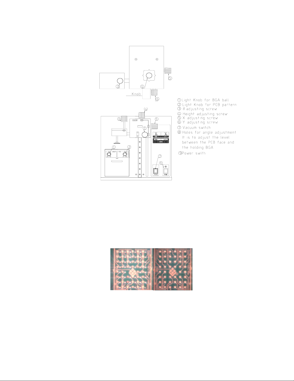
Figure 6: TF 2000P
A) Zoom in so the lands on the PCB fill the screen and center
the land pattern on the display.
B) Adjust the lighting so both images are clear.
C) Align the component to the land pattern using the X,Y and Θ.
See Figures 6 and 7.
(A) (B)
Figure 7 - Unaligned (A) and Aligned component (B) as they would appear.
6. Lower the Alignment Apparatus to PCB.
7. Release component by turning off the vacuum and return alignment
apparatus to the upper position. See Figure 6.
Page 15 of 67
Page 16
8. Using the handle on the Sliding Shaft Holder, index the table from
the Placement Position to the Reflow Position.
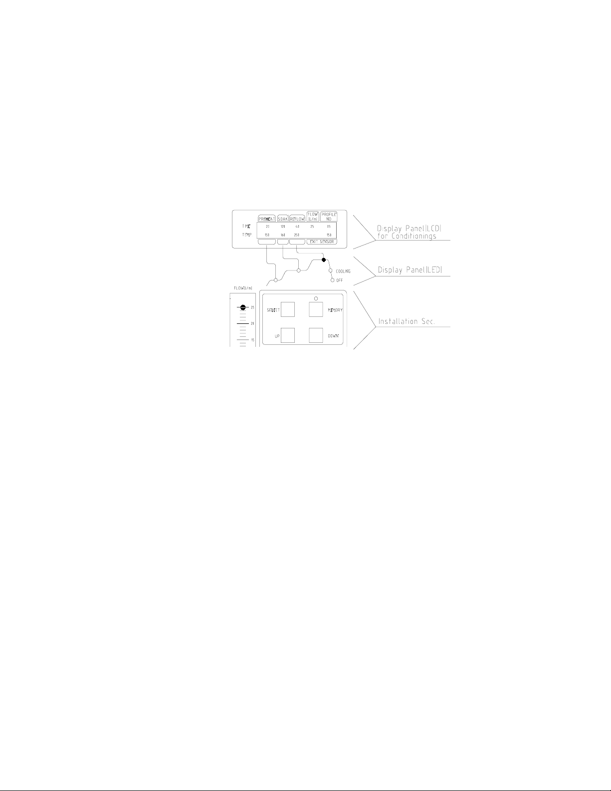
9. Select the desired profile or enter time and temperature parameters
for pre-heat, soak, and reflow phases. Those values will be shown
on the LCD display. See Figure 8. As each phase in the reflow
profile is entered, the LED indicator lights will show which phase
the process is in. See Figure 8.
Figure 8: Display and Data Entry Panel
10.Once the reflow profile has been completed, the reflow head will lift
up automatically and the cooling fan will turn on for 55 seconds.
Airflow from the cooling may be directed by loosening the locking
thumb screw on the fan and rotating it around its shaft.
Page 16 of 67
Page 17
3 EXPLANATION OF EACH OPERATION
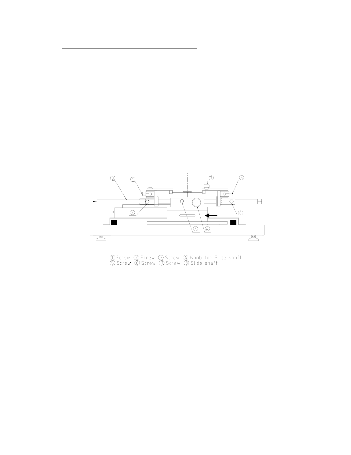
3-1 Placing BCB into Board Holder - Please see Figure 9.
1. Center the sliding shaft (8) in the holder (9).
2. Adjust the sides of the board holder so that the distance between
them is 3 mm smaller (half the width of the rail) than the width of
the PCB. Secure the sides by tightening the setscrews (6 & 2)
3. The right side of the board holder is spring loaded. Insert the PCB
into the support slots while holding the right side of the board holder
open. When the PCB is positioned, let the right side close.
9
Reflow Position Placement Position
9) Sliding Shaft Holder
Figure 9: Board Holder and Base
3-2 Component Alignment and Placement - Please refer to Figures 6
and 9.
1. Set the sliding shaft holder at the Placement Position at the far right
side of the base
2. Verify that the height (Z-axis) adjusting screw (#4, Fig. 6) is
positioned in the center of the square hole as shown in Figure 4.
This position is the reference point for all alignment procedures.
3. Extend the optical housing by pulling the handle towards you. The
lights will come on automatically.
4. Focus the array pattern on the PCB by focusing manually or by
using the AUTO FOCUS feature. When using the AUTO FOCUS
feature, switch the feature off after the array pattern has been
focused.
5. Center the PCB array pattern on the Display. Zooming in on the
array allows for easier centering.
Page 17 of 67
Page 18

6. Tighten the setscrews (#1 & 5, Fig. 9) to secure the “Y” position of
the PCB.
7. Tighten the setscrew (#3, Fig. 9) on the sliding shaft holder (#9, Fig.
9) to secure ”X” position of the PCB.
8. Switch on the vacuum switch (#7, Fig. 6).
9. Hold the component to be placed using the vacuum nozzle. See
Figure 7.
10. Adjust the lighting using the adjustment knobs (#1 & 2 Fig 5) so the
image of the PCB land pattern and the image of the solder balls on
the component can be seen clearly.
11. Adjust the height of the device with the height (Z-axis) adjusting
screw (#4 Fig 5) to bring solder balls/leads into focus. Failure to
focus the component may result in inaccurate alignment.
12. Turn the “AUTO-FOCUS” feature on after the PCB and component
are focused.
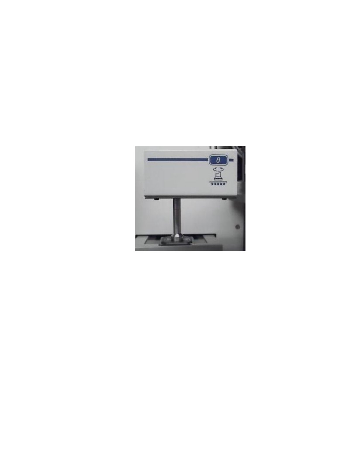
13. Adjust θ aspect of the component by turning the θ adjustment knob
(#3, Fig. 6).
14. Adjust the X and Y aspects of the component by adjusting the X
and Y adjustment knobs (#5 & 6, Fig. 6).
15. When the component is aligned (See Figure 7), return the optics
housing to its retracted position. The lights will turn off
automatically.
16. Using the handle, lift the alignment apparatus upwards by hand to
release, then lower the apparatus slowly. As the apparatus
reaches the PCB, the damper will engage to ensure the component
lands softly on the PCB.
NOTE: The alignment apparatus cannot be lowered while the
optics housing is extended.
DO NOT DROP THE ALIGNMENT APPARATUS FROM THE
UPPER POSITION.
NOTE: When repeating operations using the same PCB and
device, steps 4 and 11 may be eliminated. However,
when changing devices, it is important to include steps 4
and 11 in the initial setup procedure.
3) Confirm that the component has contacted the PCB. Turn off the
vacuum switch (#7, Fig 6).
When repeating operations using the same PCB and device, the
mechanical stop on the right side of the alignment apparatus may
be set to ensure repeatability.
4) Return the alignment apparatus to its original position.
Page 18 of 67
Page 19
19) Move the sliding shaft holder to the Reflow Position using the
handle.
NOTE: For TF 2000L/LE models, refer to the Sliding Shaft
Holder Indexing portion of Section 10 for a description of
model differences.
3-3 Component Reflow - Please refer to Figure 10
1) Make sure that an appropriately sized nozzle is fitted to the reflow
head.
2) Verify the sliding shaft holder is at the Reflow Position at the far left
side of the base
3) Select a profile or enter reflow parameters. Refer to section 4.
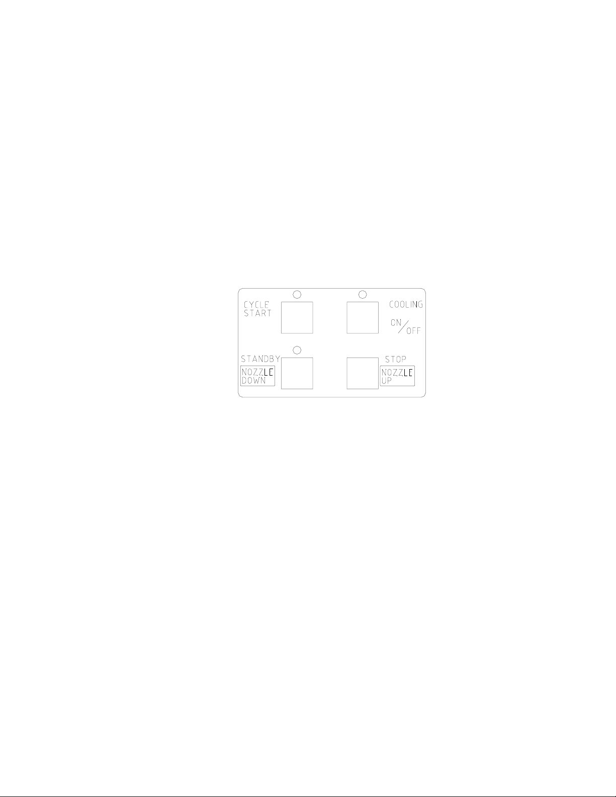
Figure 10: Operations Panel
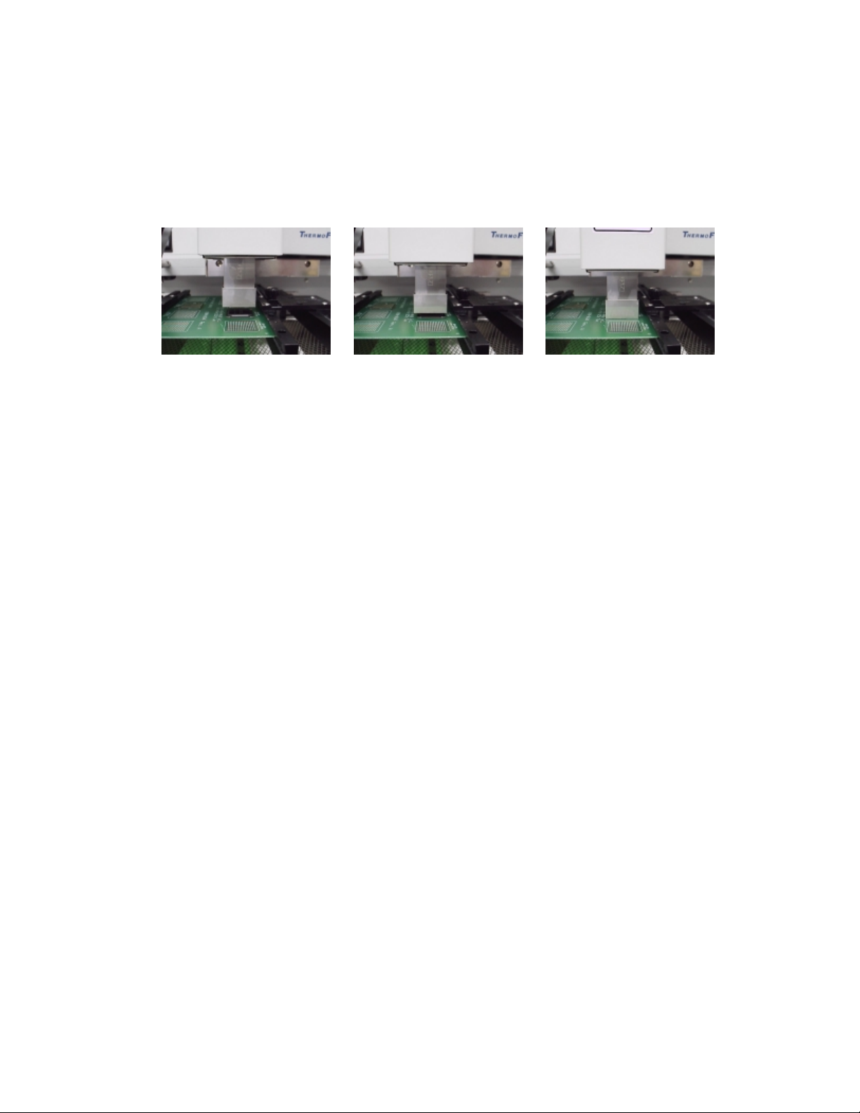
4) Push the NOZZLE DOWN button. The nozzle will go down and
stop automatically 16 mm (will vary with PCB thickness) above the
PCB. See Figure 10.
5) Confirm that the component position is aligned with the nozzle.
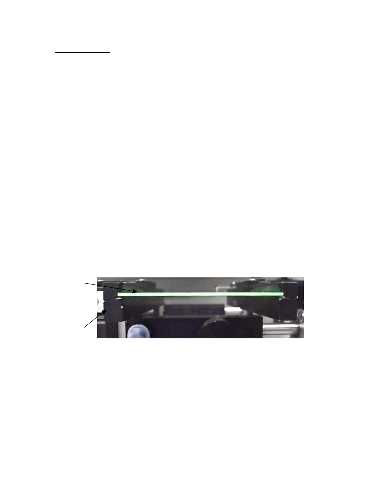
Press and hold the NOZZLE DOWN button. The reflow head will
lower itself, slowly. Lower the reflow head until there is no gap
between the nozzle and the PCB. See Figure 11. If you need to
raise the reflow head up by a slight amount, press the NOZZLE UP
button briefly.
When repeating operations using the same PCB and device, the
mechanical stop on the left side of the reflow apparatus may be set
to ensure repeatability.
The reflow head has a clutch that will engage if the nozzle applies
pressure on the PCB or the mechanical stop. This ensures the
safety of the PCB and the motor that drives the reflow head.
NOTE: In some instances the space around a component will be
insufficient to bring the nozzle into contact with the PCB.
Should this occur, select a nozzle with dimensions that
Page 19 of 67
Page 20
are similar to the component body. For reflow, position
the nozzle 1 mm above the component. The time of the
reflow cycle may have to be adjusted to insure
satisfactory results. A thermo-couple should be used to
verify reflow conditions.
Figure 11: Properly Positioned Nozzle in Relation to PCB
6) When the nozzle is properly positioned, press the CYCLE START
button. The PREHEAT LED on the Phase Display Panel will light
and the reflow cycle will begin.
7) The Phase Display Panel (See Figure 8) will indicate the phase of
the reflow cycle (PREHEAT, SOAK, REFLOW and COOLDOWN)
and the time for each phase will be counted down on the LCD
Display. An audible alarm will sound seven (7) seconds before the
end of the reflow phase.
8) When the reflow cycle is complete, the nozzle will automatically
raise and the COOLING FAN will turn on, cooling the soldered
component, PCB and nozzle.
9) Do not remove the PCB from the board holder until the COOLING
LED has gone off and the OFF LED is lighted.
3-4 Adjusting Airflow
1) The knob on the air flow meter adjusts the air flow. Make sure to
match the air flow meter value with the value of FLOW on the
LCD Display. The actual air flow will not be changed by the flow
value of the display panel.
3-5 Component Removal
1) Component removal is accomplished in the same way as the
reflow.
2) When the audible alarm signals 7 seconds before the end of the
reflow phase, push the VACUUM button to turn on the vacuum
pump.
3) Once the reflow head raises up, remove the component by using
the hand held vacuum pick.
4) It is possible to shorten the profile for removals.
Page 20 of 67
Page 21

4 SELECTING A PROFILE
Please refer to Figure 8 for this section.
1. Using the SELECT button, move the cursor to the PROFILE NO.
position.
2. Select a profile by pressing the UP or DOWN buttons. The TF
2000 can store up to 40 profiles. Profile memory locations from 00
to 39 are available. The TF 2000 comes with three profiles loaded
(locations 00, 01, and 02). These should be used as baselines
when creating profiles. User profiles can be stored in locations 03
through 38. Location 39 is used as a working memory when
profiles are downloaded from a PC. See Software section. The
profile parameters in use are visible on the LCD display.
5 CREATING AND SAVING PROFILES
Please refer to Figure 8 for this section.
5-1 General Information
The TF 2000 comes with three profiles already installed that should be
used as baselines when developing profiles. The profile in memory
location 00 is recommended as a starting point for area arrays smaller
than 35 mm square. The profile in memory location 01 is
recommended for reflowing area arrays 35 mm square and larger.
Profile number 02 is essentially the same as profile number 01, but
adds a temperature spike (30 °C) from the Bottom Side heater during
the reflow phase.
5-2 How to install a profile:
1) Using the SELECT button, move the cursor to the item to be
changed.
2) Change the value by pressing the UP or DOWN button.
3) After all values have been set, press the MEMORY button once.
The LED above the MEMORY button will go on.
4) Press the SELECT button to move the cursor to PROFILE NO.
5) Using either the UP or DOWN button, choose a profile memory
location (03 through 38) to save the profile into.
6) When the memory location has been selected, press the MEMORY
button until the audible signal is heard indicating the profile has
been saved to the memory location selected.
7) Once the profile has been saved, the LED lamp will go out.
Page 21 of 67
Page 22

NOTE: The above procedure can be used to create and save new
profiles and to modify existing profiles. Saving a profile to
a memory location that is in use will overwrite the existing
profile.
5-3 Additional Information
1) Temperature settings are as follows:
• Preheat Temp is the temperature of the bottom side heater
• Soak Temp is the set temperature of the top heater during
soak, bottom heater remains at “pre-heat” temp.
• Reflow Temp is the temperature of the top heater during
reflow. The bottom-side heater can either remain at its set
temp or a “Spike” of 30 degrees C may be set. See
Software Section.
2) Time and temperature parameters can be changed while a reflow
cycle is running. However, the PROFILE number itself can not be
changed.
3) To decide a temperature value, it is recommended to use a thermocouple to take temperature measurements. Profile creation is most
successful when thermo-couples are used. For assistance, contact
PACE.
4) To ensure a successful installation the following conditions should
be met in each profile.
During the PRE-HEAT phase, the PCB should experience a
temperature of between 95 and 105 ºC before entering into
SOAK
During the SOAK phase, the solder balls should experience a
temperature between 140 to 160 ºC for 45 to 60 seconds.
During the REFLOW phase, the solder balls should experience
a temperature of 205 to 220 ºC for 10 to 20 seconds.
5) The preset default profiles located in memory locations 00-02 are
as follows: (Time/Temperature)
Profile Preheat Soak Reflow
00 60/180 100/110 100/230
01 61/210 100/140 120/280
02 60/210 100/140 130/280
NOTE: Above values are expressed as seconds/°C.
Page 22 of 67
Page 23

6) During the Reflow phase, the Bottom Side heater provides a 30 °C
temperature spike to aid in the reflow process. This is an automatic
feature and can be disabled by entering “61” seconds in the
Preheat time field prior to the start of the reflow cycle. The “SPIKE”
allows for more even heating of PCB and Device as well as lower
“REFLOW” temperatures.
Page 23 of 67
Page 24

6 PC SOFTWARE
TF2000 application software comes pre-installed on the optional PC
configuration of the TF 2000 BGA/CSP Rework System. The software
provides numerous features not included with the standard monitor
configuration. These features include:
• Allows password to be entered to restrict creation and modification
of existing profiles.
• View images from the Vision Overlay System (VOS).
• The ability to save images electronically.
• Real time split screen function allows for quick alignment of large
components or components with numerous solder balls.
• Use up to 2 Thermo-Couple Sensor Inputs to monitor reflow profile.
• Time and Temperature parameters are displayed on screen.
• Incorporate work instructions for operators into profiles.
• Ensures process control by restricting operator access to profile
parameters.
• Allows for process validation using a thermo-couple.
• Document operations for quality assurance.
The TF 2000 application software consists of 5 operational screens
indicated by folder tabs across the top of the display. Click on the
associated folder tab to access the operational screen.
Page 24 of 67
Page 25

6-1 Setup Tab
The Setup screen allows for the configuration of the TF 2000 software.
Figure 12: Setup Tab
1) Setup Password Button – Restricts access so that profiles can not
be modified, deleted, or created by unauthorized users. Clicking
this button causes a pop up box to be displayed. (See Figure 13)
2) Select Language – Allows for selection from 6 different languages,
including English, German, French, Italian, Spanish and Swedish
from a drop down menu.
3) Video Image Flip – Provides a means to vertically or horizontally flip
the camera image (on the Optical Alignment screen) by digitally
manipulating the displayed image.
4) Video Image Rotation – Rotates the displayed image (on the
Optical Alignment screen) by the amount indicated for the selected
field.
NOTE: Selecting any of the Video Image Flip or Video Image
Rotation options may cause the displayed image to
Page 25 of 67
Page 26

appear “jerky” or “sluggish”, due to the calculation
time required to digitally flip or rotate an image.
5) Select Sensor trace to save with Profile – Allows one or both
thermocouple (sensor) inputs to be saved with any given profile.
6) Local PACE Representative Phone Number – Allows for entry of
PACE Local Representative or PACE customer service telephone
number for easy reference.
7) Set Upper and Lower Temperature Limits – Provides a reference
zone for reflow, typically set at 195 and 220°C. Horizontal green
lines on the graph represent upper and lower limits.
Figure 13: Password Setup Box
Page 26 of 67
Page 27

6-2 Optics Tab Alignment View
This screen is used for aligning the component solder balls to the PCB
land pattern using the vision overlay system (VOS). Camera Zoom
and Focus can be controlled from this screen as well as the Real Time
Split Screen feature.
Figure 14: Optics Tab Alignment View
Zone 1: The lower left-hand corner and the upper right-hand
corner up to the diagonal lines marked “1”.
Zone 2: The lower left-hand corner and the upper right-hand
corner up to the diagonal lines marked “2”.
**Refer to Figure 15 for an example of Real Time Split Screen
images.
Page 27 of 67
Page 28

(A) (B)
Figure 15: Results from the Real Time Split Screen Feature
Zone 1(A) and Zone 2(B)
• To access Zone 1, click anywhere in Zone 1.
• To access Zone 2, click in between the diagonal lines
marked “1” and “2”.
• Click anywhere on the Zone 1 or Zone 2 image to return
to the original image.
1) Image Area - Shows overlay image of device and PCB for quick
and easy alignment.
2) Real Time Split Screen feature – Provides 2 zones of split
magnification. (Refer to Figure 14) The diagonal lines on the
display indicate the zones.
3) AutoFocus/Manual Button – Allows the operator to toggle the
camera focus control between manual and auto focus.
4) Zoom Slide Bar – Controls the amount of zoom from Wide to
Telescopic viewing.
5) Focus Slide Bar – Allows focus to be adjusted
6) Review Button – Allows previously saved image to be recalled.
7) Capture Button – Saves current image to “Capture” folder or
location of choice.
8) Video Selection – Image from TF 2000 is displayed.
9) Inspection Selection – Image from Inspection Device is displayed.
Page 28 of 67
Page 29

6-2.1 Optics Tab Inspection View
This Screen is used in conjunction with the XR 2000 X-Ray Inspection
System. Real time X-Ray video can be viewed, stored and compared to a
reference library of common faults or desired results.
The Review and Capture Buttons operate the same as in Alignment View. The
Arrow Buttons scroll between images stored in the reference library.
To Add a Reference Image: Any Image captured as a .bmp file may be
converted to a .tif image using the “Imaging” program (located on the Windows
Accessories Menu) and added to the “XrayLib” folder under the TF 2000
Software directory.
Page 29 of 67
Page 30

6-2.2 Print/Review Tab
This Screen allows the operator to recall and view saved profiles and
operator records and output them to a specified printer.
1) Open Profile Button – Loads saved profile from disk and
displays it on screen.
2) Open Record Button – Loads saved operator record and
displays it in Record Comment.
3) Overlay Profile Button – Inserts a previously saved profile on
screen to compare the currently viewed profile to.
4) Overlay Record Button – Inserts previously saved record on
screen to compare currently viewed record to.
5) Close All Button – Clears all opened and overlaid Profiles and
Records.
6) Print Preview Button – Opens Print Preview Screen
7) Print Button – Brings up Print Screen to select printer to output
displayed record or profile.
Print Review Tab
Page 30 of 67
Page 31

6-3 Operation Tab
With the exception of the optical alignment, this screen allows the
operator to perform all essential operations including profile selection,
documenting operations for quality assurance, and process validation.
Page 31 of 67
Page 32

Page 32 of 67
Page 33

Figure 16: Operation Tab
1) Profile Name – Allows the operator to select the proper profile from
a dropdown menu. When a profile is selected, the profile
parameters are automatically downloaded to the TF 2000 working
memory, profile #39.
2) Profile Instructions – Displays instructions pertinent to the selected
profile.
3) Record Comment area – Provides a means for documenting
essential information.
4) Save Record Button – Stores profile name, date & time, operator
comments and graph information in “Records” folder.
5) Progress Indicator – Visual indication of the profile process.
NOTE: A record is defined as information associated with a
particular rework job. This information includes profile
parameters (via the graph), sensor input, and
operator recorded comments. A record can be saved
for each new component installation. When a record
is saved, the date, time and profile name are
automatically stored with that record.
6) Graph area – Graphically displays profile parameters (time and
temperature) and a sensor input. The box next to Sensor 1 in the
right hand margin must be checked to activate this function.
Page 33 of 67
Page 34

6-3.1 Process Control/Validation Feature
Figure 17: Process Validation
During the Profile Development phase, a temperature probe trace can
be saved with an associated profile. A reference point near the
component rework area (on an adjacent component lead for example)
must be used for temperature probe placement. Location can be
stored in “Profile Instructions”. Keep in mind that data must be
collected from the same Temp probe place at the selected location
when saving profile temperature and rate with the profile.
When an operator selects an appropriate profile, the temperature
probe trace will be displayed on the graph in blue. To validate the
rework process, the operator can place the temperature probe on the
designated reference point, check the box next to Sensor 1 in the right
hand margin and run the profile. As the profile progresses, the
temperature probe trace will be displayed in red. The two probe traces
can be compared to validate a particular rework process. (See Figure
17) Some variation may exist due to differences in Temp probes,
positioning, and operator error. The “shape” of the curves should be
similar.
Page 34 of 67
Page 35

6-4 Profile Development Tab
This screen is designed for the profile development engineers. Access
to this screen can be password protected. Profiles can be created,
modified, and/or deleted from this screen. Specific operator
instructions applicable to a particular profile can also be entered from
this screen.
Page 35 of 67
Page 36

Page 36 of 67
Page 37

Figure 18: Profile Development Tab
1) Profile Name and Parameters (upper left-hand corner) – Allows the
operator to select a stored profile and displays time and
temperature settings for each phase of the Reflow cycle.
2) Instruction Box – Provides a means to store and display operator
instructions applicable to the selected profile. Instructions may
pertain to
such items as nozzle type, type of solder paste or flux, reference
position of temperature probe for process validation, and any other
special needs.
3) “New” Button – Clears Profile Name field and resets all profile
parameter fields to 0. Allows the operator to enter the new time
and temperature values for each phase of the Reflow cycle.
4) “Save Profile” Button – Saves profile parameters for the selected
profile. Clicking this button will overwrite existing profile parameters
for named profiles. A pop-up box will appear for new unnamed
profiles.
5) “Transfer Profile” – Transfers the selected profile to the working
memory in the TF 2000. The working memory is profile number 39
on the TF 2000. Profile parameters transferred to the working
memory will automatically be displayed in the LCD window on the
TF 2000.
6) “Save As” Button – Used for renaming profiles and naming new
profiles. A pop-up box will appear when pressed.
7) “Reset” Button – Clears sensor input lines from the graph.
8) “Save Excel” Button – Saves profile in .csv format that can be
opened in MS Excel.
9) “Delete Profile” Button – Deletes the selected profile from the PC.
Deleted profiles cannot be retrieved.
10) Graph Area – Graphically displays profile parameters (time and
temperature) and sensor inputs. Right Clicking the mouse on any
area of this graph will display the temperature at the point selected.
Left clicking the mouse on any two points will give the temperature
slope rate between the two points.
6-4.1 General Information concerning the Profile Development
Screen
1) The Reflow Graph area displays a representation of the Reflow
cycle profile. Time in minutes is graphed along the X-axis and
temperature in degrees Celsius is plotted along the Y-axis. The
time and temperature axes incorporate a dynamic scaling feature to
optimize the display for extremely short or long profiles. Profile
graphs can be saved with profiles to be used for process validation
by operators while using the Operation screen. Profile graphs can
Page 37 of 67
Page 38

also be stored as individual records for each rework job for quality
control purposes. Solid and dotted lines are used to indicate profile
parameters.
a) Horizontal Green Lines – Indicates upper and lower temperature
limits as set on the Setup Tab.
b) Horizontal Dotted Line – Indicates the Bottom Heater set
temperature. The dotted line becomes solid as the reflow cycle
progresses.
c) 3-Tiered Dotted Line – Indicates Top Heater activity for each
phase of the reflow cycle. The dotted line becomes solid as the
reflow cycle progresses.
d) Red Line – Sensor 1 temperature over the period of the reflow
cycle. Sensor 1 Box must be checked to allow for display of the
sensor input.
e) Blue Line – Sensor 2 temperature over the period of the reflow
cycle. Sensor 2 Box must be checked to allow for display of the
sensor input.
Each Sensor input has a Temp and Peak field (right hand margin)
associated with it. The Temp reading displays the current temperature
reading and changes as the reflow cycle progresses. The Peak
reading displays the highest temperature measured during the reflow
cycle.
Page 38 of 67
Page 39

Figure 19: Sample Profile Development Screen
2) Profile parameters can be changed while the profile is running.
Perform the following procedure to modify profile parameters while
the profile is running:
a) On the TF 2000, press the “Select” button until the cursor is at
the parameter field to be changed.
b) Press the “UP” or “DOWN” buttons to change the selected field.
Numeric values change by increments of 2 for each press of the
“UP” or “DOWN” button. See Figure 20.
Page 39 of 67
Page 40

Figure 20: LCD Display and UP and DOWN Buttons
As the profile parameters are changed on the TF 2000, the profile
parameter fields on the Profile Development screen will change to
reflect the increase or decrease in time. The dotted lines on the graph
will also change to reflect the new parameters. The Time fields on the
software reflect “total” time after modification.
6-4.2 Profile Creation
There are 2 recommended methods for developing a profile. The first,
involves an actual component installation, while the second uses a
previously installed package. Either method can be used to develop a
reliable profile. However, there are some issues and considerations to
be aware of with each.
When developing profiles through actual component installation, it is
critical to make sure the thermocouples remain in contact with the
solder balls throughout the entire process. Unreliable data will be
collected should a thermocouple lose contact with the solder balls. If
Page 40 of 67
Page 41

measuring the temperature on the top of the package it is best to use a
preinstalled component.
When using a previously installed package, the placement of the
thermocouples is important. They must be in contact with the existing
solder joints. This task is best accomplished by drilling through the
bottom of the PCB into a solder joint and attaching the thermocouple or
by sliding the thermocouple under the package. When sliding a
thermo couple under a component, it is critical that the thermo couple
be in contact with a solder ball.
Information from the thermocouples will assist in determining the
proper time and temperature parameters. In general, the following
guidelines should be adhered to when developing profiles.
Ramp and Maximum Temperatures
Acceptable ramp rates and maximum temperatures should be obtained
from the package manufacturer. It is recommended to select a
maximum temperature below the manufacturer’s specification to
provide for a margin of safety. Typically, 20 °C below maximum is
selected.
Pre-Heat Phase
1. In a “step profile”, the top of the PCB and package should reach a
stable temperature of 95-105 °C. If plotting the temperature curve,
the trace should level off within this temperature range.
2. If a “linear slope” is desired, pre-heat and soak phases are
combined. Both the package and the PCB are warmed at a
constant ramp rate (usually 1-3 °C/second) until the desired soak
temperature is reached.
Soak Phase
The soak phase is a crucial part of the reflow process. During this
period, the flux activates and drives off volatiles and excess flux. A
stable temperature of 145-170 °C (determined by the activation
temperature of the flux used) should be maintained for approximately
40-60 seconds. This allows for uniform ramping across the entire
package and PCB during reflow.
Reflow Phase
Page 41 of 67
Page 42

During this phase, the solder balls reach solder melt and form a joint
between the package and the pads. It is critical for all areas of the
array to reach solder melt together and all solder balls remain in a
liquid state for at least 15-20 seconds.
Generally, the device should not be exposed to temperatures higher
than 220 ºC. Always consult the device specifications for maximum
temperature recommendations. As a rule of thumb, a safe “maximum
temperature” is the maximum temp specified by the manufacturer
minus 20ºC. Lower temperatures and shorter times are common in
CSPs and FCs. The lowest temperatures possible should always
be used to ensure safety of the device and PCB.
Cool Down Phase
The cool down phase is necessary to bring the temperature of the
package, solder joints and PCB under the package below solder melt
temperatures. Cooling should be controlled. A good reference is to
use the same cool down rate as for ramp up. The cooling fan on the
TF 2000R will remain on for 55 seconds from the start of the cool down
cycle. Some types of components (like CBGAs) should be allowed to
cool without external assistance from the cooling fan.
General
Using the baseline defaults in memory locations 00, 01 and 02 will provide
a good starting point for profile development. The reflow graph provides
an excellent tool for monitoring profile parameters and fine tuning or
perfecting the profile development process.
When adjusting profile parameters “on-the-fly”, all changes are reflected
immediately on the profile development screen and graph.
Page 42 of 67
Page 43

7 MAINTENANCE
The TF 2000 is designed to operate with a minimum level of maintenance.
However, replacement of some parts will be required from time to time.
Please follow the maintenance instructions below when replacing parts. If
there are any questions, contact PACE.
CAUTION: Disconnect the main power supply and computer
7-1 Cleaning the Blower Filter
Clean the filter every three (3) months.
1) Take off the cover on the back of the TF 2000R. Please see
Figure 2.
2) Loosen the butterfly screw fitted inside.
3) Remove the filter from the housing.
4) Clean the inside filter using warm water.
5) Make sure the filter is dry before re-assembly.
cables, if applicable, BEFORE opening the TF 2000B,
TF 2000BE, TF 2000BL, TF 2000BLE, TF 2000R, TF
2000P, BEFORE replacing any component of the TF
2000, and BEFORE performing ANY routine
maintenance.
7-2 Replacing the Top Heater
Please refer to Figure 21 for heater replacement.
1) Disconnect the TF 2000 from ALL power supplies.
2) Remove the protective cover from the reflow head by removing
the four screws on the left side.
3) Loosen the two screws in the terminal block that affix the wires
from the top fan.
4) Set the fan aside.
5) Loosen the two bolts on the top of the assembly.
6) Lift off the connectors that secure the wires from the power
indicator lamp on the front of the protective cover.
7) Set the cover aside.
8) Lift off the heater wires from the mounting posts.
9) Remove the terminal block taking out the two screws that
secure it to the assembly.
10) Pull off the rubber hose from the connection on the top of the
assembly.
11) Loosen the three Philips head screws from the sides of the
housing and the hex bolt in the back that secure the top cover
of the assembly
Page 43 of 67
Page 44

12) Lift off the cover and pull out the heater.
13) Replace heater and reassemble assembly.
Figure 21: Heater Assembly
Page 44 of 67
Page 45

8 ALIGNMENT & CALIBRATION
All PACE TF 2000 BGA/CSP Rework Systems are factory aligned and
calibrated prior to shipment. Due to adverse shipping and handling
conditions, it may be necessary to perform one or more of the following
alignment and calibration procedures prior to use. Proper alignment and
calibration of system components should also be performed on a semiannual basis to ensure peak performance.
8-1 Board to Optics Aalignment
This alignment should be performed when the land pattern on the PCB
appears skewed on the video display.
NOTE: For TF 2000L/LE models, refer to the Alignment and
Calibration Differences in Section 10.
1) Position testing PCB in Board Holder.
2) Pull the optics housing out from the front of the TF 2000P using the
handle.
3) Zoom in so the lands on the PCB fill the screen.
4) Observe land pattern. If land pattern is skewed, proceed to step 5.
See figure 22. If land pattern appears aligned, omit steps 5-7.
5) Loosen 8 setscrews found on both sides of the board holder.
6) Shift the board holder by hand until the image is no longer skewed.
7) Retighten setscrews, alternating from one side of the board holder
to the other, until all 8 setscrews are tight.
Figure 22: Skewed Land pattern
Page 45 of 67
Page 46

8-2 Sliding Shaft Holder Alignment (Indexing)
This alignment will correct X aspect errors when indexing the sliding
shaft holder from the placement position to the reflow position and vice
versa.
NOTE: For TF 2000L/LE models, refer to section 10 for the
Sliding Shaft Holder Alignment.
NOTE: A reference point must be established for this
procedure. The reflow position will serve as a
reference point for this alignment calibration.
1) Position testing PCB in the board holder.
2) Set the sliding shaft holder at the reflow position flush against
the left indexing tab.
3) Lower reflow heater nozzle to approximately 1/8” above a PCB
component.
4) Visually center component in the “X” direction under nozzle
using the adjustment knob on the sliding shaft holder.
5) Using the handle on the sliding shaft holder, index the table
from the reflow position to the placement position.
6) Pull the optics housing out from the front of the TF 2000P using
the handle.
7) Zoom in so the lands on the PCB fill the screen.
8) The land pattern should be centered on the display horizontally
(X direction). If centered, omit steps 9-16. Otherwise, proceed
to step 9.
9) Set the sliding shaft holder in between the reflow and
placement position.
10) Remove rubber stopper from right indexing tab on the base
assembly.
11) Loosen center set screw on top of right indexing tab. See
Figure 23.
12) Depending on the direction and amount of offset in the X plane,
tighten or loosen the large setscrew on the side of right
indexing tab.
Note: Tightening the large setscrew will shift the displayed
image to the right. Loosening the same setscrew
will shift the image to the left.
13) Reinstall rubber bumper on large setscrew.
14) Return sliding shaft holder to the placement position.
Page 46 of 67
Page 47

15) Observe proper centering of land pattern on video display. If
centered, proceed to step 16. Otherwise, repeat steps 9-14
until proper centering is achieved.
16) Tighten center set screw on top of right indexing tab.
Figure 23: Top and Side View of Indexing Tab
8-3 Vacuum Nozzle Planarity
The Vacuum Pick nozzle must land flush on the PCB component in
order to achieve parallelism and adequate suction. Performing the
following procedure can rectify problems in vacuum nozzle planarity.
1) Remove the cover on the Alignment Apparatus by removing the
three bolts on the top of the cover and the “Y” adjustment knob.
The “Y” adjustment may have to be brought forward to allow the
cover to clear the shaft.
2) Place a PCB on the board holder and install the large nozzle.
3) Lower the alignment apparatus to the PCB.
NOTE: To achieve parallelism in the “X” direction, perform
steps 4-7. In order to achieve parallelism in the “Y”
direction, perform steps 8-11.
Page 47 of 67
Page 48

Figure 24: Three vertical setscrews on the alignment apparatus
8-3.1 X Correction Refer to Figure 24
1) Loosen the top 2 setscrews facing the front of the alignment
apparatus.
2) Lightly press right over the vacuum pick to suck the PCB.
3) Turn the “Z” knob right or left to meet the parallel face of the
vacuum pick nozzle and the PCB. When parallel, the vacuum
noise will be low.
4) Retighten the 2 setscrews while maintaining light pressure over the
vacuum pick assembly.
8-3.2 Y Correction Refer to Figure 24
1) Loosen the bottom setscrew facing the front of the alignment
apparatus.
2) Lightly press right over the vacuum pick to suck the PCB.
3) Turn the “Z” knob right of left to meet the parallel face of the
vacuum pick nozzle and the PCB. When parallel, the vacuum
noise will be low.
4) Retighten the bottom setscrew while maintaining light pressure over
the vacuum pick assembly.
8-4 Reflow Head Planarity Alignment
When lowered and properly aligned, the nozzle on the reflow head
should land flush with the PCB. Errors in reflow head planarity (both X
and Y aspects) can be corrected by performing the following
alignment.
8-4.1 X Correction
Page 48 of 67
Page 49

1) Position the test PCB in the board holder and index the sliding
shaft holder to the reflow position.
2) Lower reflow head and nozzle to just above the PCB.
3) Turn off the power to the Reflow unit.
4) Loosen 2 setscrews located on the backside of the reflow head,
on both sides of the arm that extends out to the reflow head.
NOTE: Allow ample time for cooling before handling the reflow
head.
5) Adjust position of the reflow head by hand until parallelism is
achieved in the “X” direction.
6) Retighten 2 setscrews on the back of the reflow head while
holding reflow head in correct position.
8-4.2 Y Correction Refer to Figure 25.
1) Remove the screws on the front and back of the base assembly,
which are used to secure the Reflow unit to the base unit.
2) Remove the reflow assembly from the base and place on a
stable platform.
3) Remove 8 philips head screws securing the housing for the
Reflow unit and slide the housing assembly off.
4) Loosen 4 setscrews on the reflow head arm, located directly
behind the front panel.
5) Manually adjust the reflow head until parallelism is achieved in
the “Y” direction.
6) Retighten 4 large setscrews maintaining position of reflow head.
Adjustment
Setscrews
Adjustment
Setscrews
Figure 25: Y Correction setscrews for Reflow Head Planarity Alignment
8-5 Reflow Head – “Y” Directional Adjustment
Page 49 of 67
Page 50

This adjustment should be performed when the Reflow Head is either
too far forward or too far back (“Y” aspect) when lowered down onto
the PCB. If the nozzle does not land flush (planar) on the PCB,
perform the Reflow Head Planarity alignment before this adjustment.
NOTE: Ensure the nozzle assembly is properly seated in the
Reflow head. If the nozzle if improperly seated, the nozzle
and Reflow head may appear to be too far forward when
lowered down onto the PCB.
1) Remove the screws on the front and back of the base assembly,
which are used to secure the Reflow unit to the base unit.
2) Remove the reflow assembly from the base and place on a
stable platform.
3) Remove 8 philips head screws securing the housing for the
Reflow unit and slide the housing assembly off.
4) Place the reflow assembly (uncovered) back on the base and
secure with the screws on the front and back.
The Reflow Head is attached to a vertical structure (block) that
is secured to the bottom of the reflow unit by 2 allen head
screws.
5) Locate the slot for the allen head screws on the underside of the
base assembly directly under the reflow head.
6) Loosen the two allen head screws.
7) Slide the vertical structure either forward or back to compensate
for the “Y” directional aspect error of the Reflow Head.
8) When the “Y” aspect error is corrected, retighten the 2 allen
heads.
9) Re-install the cover on the reflow unit.
Page 50 of 67
Page 51

9 GENERAL TROUBLESHOOTING
The following procedures are designed to allow the operator to perform
basic visual inspections of system components. (ie. loose connections,
equipment misalignment, etc.) If you ever have any questions, contact
PACE.
Page 51 of 67
Page 52

Initial Operation
g
The Reflow unit will conduct an initialization sequence each time the
power is turned on. The following flow diagram can be used to isolate
failures during this initialization sequence.
POWER ON
Power and Off
LEDs are lit,
LCD is on, and
Cycle Start LED
is flickerin
AIRFLOW
ON
18-25 l/min
TOP
HEATER
ON,
SENSOR
TEMP
< 250°C
TOP
HEATER
OFF IN 30
SEC., AND
FLOW IS
OFF IN 20
SEC.
.
1. Check AC power input
2. Are circuit breakers tripped?
3. Check electrical connection on
PCB RD200c
1. Is knob open at Flow meter?
2. Check CR1 of PCB RD200Po
1. Check connections of CN3 and
CN9of PCB RD200Po
2. Check BCR1 of PCB RD200Po
(Warning Buzzer is buzzing)
1. Check for breakage of Sensor
Connection, CN10 of PCB RD200c.
2. Check for breakage of Heater
Connection, CN9 of PCB RD200c.
BOTTOM
HEATER
LAMP IS ON
AND
FLICKERS
AFTER 3 MIN.,
BOTTOM
HEATER
TEMP IS UP
INITIAL
OPERATION
OVER
Page 52 of 67
Check BCR2 of PCB RD200Po
Page 53

Nozzle Up/Down Operation
N
N
PRESS THE “STAND BY”
BUTTON
OZZLE
COMES
DOWN,
STAND BY
LAMP ON
PUSH THE “STOP”
BUTTON
OZZLE
COMES UP,
STAND BY
LAMP IS
OFF
1. Check connection CN2
of PCB RD200c.
2. Possible faulty
components: IC9 or R107
of PCB RD200c.
END
Page 53 of 67
Page 54

Vacuum Nozzle Operation
N
PRESS VACUUM BUTTON
TO TURN VACUUM ON
USING YOUR
FINGER,
CHECK FOR
SUCTION AT
THE END OF
THE VACUUM
PICK NOZZLE
Remove housing cover of the
Positioning unit. Check Pump
and Leak valves, M1 and S1, and
associated hoses.
WHEN
LOWERED,
VACUUM PICK
OZZLE
SHOULD LAND
FLUSH ON THE
COMPONENT
(PARALLEL)
END
Perform Vacuum Nozzle
Planarity calibration (See page
39)
Page 54 of 67
Page 55

General Troubleshooting
SYMPTOM CORRECTIVE ACTION
Profile memory not storing profiles. Check battery back up connection to
CN5 of PCB RD200c.
Land pattern on PCB appears
skewed or crooked on video display.
Reflow head is not parallel with PCB Perform Reflow Head Planarity
Lamps in the optical housing
assembly are not operational.
The camera does not operate. Check the wiring and connection of
Perform Board to Optics Alignment.
(See page 37)
Alignment. (See page 41)
1. Replace failed lamp or lamps.
2. Check transistors T1 (PCB side)
and T2 (BGA side), or Microswitch S1 located on the chassis.
the camera. If nothing is found
abnormal, replace the camera.
Page 55 of 67
Page 56

10 TF 2000 L/LE MODEL DIFFERENCES
Figure 26: TF 2000L/LE Model
The TF 2000L/LE models are designed for rework and repair of larger PCBs.
With the exception of the Bottom Side Heater, the Reflow and Placement
stations are identical to the standard model. There are actually 2 Bottom Side
heaters to provide bottom-side heating. The rails for the board supports are
significantly longer than the standard model as well. These differences will be
discussed in greater detail in the following paragraphs.
10-1 Installing the PCB Holder
1. Place the “Rail” between the two rows of bearings on the base of
the TF 2000 L/LE.
2. Place sliding shaft holder onto slide with the knob facing out.
3. Install two screws on each side of the sliding shaft holder to secure
board holder.
4. Install board supports by laying them across the front and back rails
as indicated in Figure 27.
Page 56 of 67
Page 57

10-2 Bottom Side Heaters
The larger version of the TF 2000 houses 2 bottom-side heaters. The
large bottom heater is movable in both the X and Y direction and is
designed to heat the overall PCB. (See Figure 27) The TEMP knob
on the bottom heater Switch Panel (See Figure 28) controls the
temperature variation for the movable Bottom Side heater.
Figure 27: Both Bottom-Side Heaters
Figure 28: Switch Panel for the Movable Bottom Heater
Page 57 of 67
Page 58

TEMP knob settings:
TEMP knob set to 10 = 130 °C on the PCB
TEMP knob set to 8 = 80 °C on the PCB
**TEMP knob should be set at 8 or above during normal use
The small bottom-side pre-heater (located directly below the Reflow head)
is non-movable and designed to provide intense heat directly under the
BGA placement area. The temperature is controlled via the temperature
profile.
10-3 Sliding Shaft Holder Indexing
In the standard model, the Sliding Shaft Holder slides freely from the
placement position to the reflow position. For the TF 2000L/LE
models, a locking mechanism must be released to index the Sliding
Shaft Holder from one position to the other. A ball joint located on
either side of the Sliding Shaft Holder seats into the locking
mechanism. See Figure 29. To release the lock in the placement
position, push the handle on the Sliding Shaft Holder to the right. The
lock will release and spring tension inside the locking mechanism will
push the Sliding Shaft Holder towards the Reflow position. When
locked in the Reflow position, push the handle on the Sliding Shaft
Holder to the left to release the lock.
Figure 29: Ball Joint and Locking Mechanism
Page 58 of 67
Page 59

10-4 Alignment and Calibration Differences
With the exception of the Board to Optics and Sliding Shaft Holder
(Indexing) alignments, all alignments and calibrations are performed as
previously described in Section 7.
The Board to Optics alignment is performed in essentially the same
manner as the standard version. The only difference is on Step 5.
Phillips head screws need to be loosened instead of Allen head
setscrews.
The Sliding Shaft Holder Alignment (Indexing) for the TF 2000L/LE
model is slightly different due to the locking mechanisms at the Reflow
and Placement positions. Use the following procedure to perform this
alignment.
NOTE: A reference point must be established for this
procedure. The reflow position will serve as a
reference point for this alignment calibration.
1) Position the test PCB in the board holder.
2) Set the sliding shaft holder at the reflow position flush against
the left indexing tab.
3) Lower reflow heater nozzle to approximately 1/8” above a PCB
component.
4) Visually center component in the “X” direction under nozzle
using the adjustment knob on the sliding shaft holder.
5) Using the handle on the sliding shaft holder, release the locking
mechanism and index the table from the reflow position to the
placement position. Be sure the lock latches.
6) Pull the optics housing out from the front of the TF 2000P using
the handle.
7) Zoom in so the lands on the PCB fill the screen.
8) The land pattern should be centered on the display horizontally
(X direction). If centered, omit steps 9-11. Otherwise, proceed
to step 9.
9) Loosen the 4 Phillips head screws on the mounting bracket for
the placement position locking mechanism. (See Figure 30)
10) Shift the mounting bracket to the right or the left until the image
appears centered on the display.
11) Re-tighten Phillips head screws.
Page 59 of 67
Page 60

Figure 30: Locking Mechanism Mounting Bracket (Top View)
Page 60 of 67
Page 61

11 SPECIFICATIONS
1. Heater (top-side): Convective style, 1200 W heater
Operating Temperature Range: 100ºC – 500ºC
2. Pre-heater (bottom-side): Light IR 400 Watt (200 W x 2)
Operating Temperature Range: 100ºC – 260ºC
Standard Pre-heater Size: 220mm x 155mm (8.6” x 6.1”)
Large version Pre-heater Size: 340mm x 470mm (13.3” x
18.5”)
3. Heating control: K type thermo-couple with closed-loop control
4. Applicable Devices: BGA, CSP, LGA, BCC and etc. Max. 50 mm x
50 mm
5. Maximum PCB Size: Standard 360 mm (14”) x 430 mm (17”)
With Optional Long Rails or L version: 500 mm (19.5) x 430 mm
(17”)
6. Airflow MAX: 25 l/min.
7. Component Adjustment Range of X,Y & Z: ±10 mm (±.4”)
8. Adjusting volume of X, Y & Z: 0.5 mm (0.02”) per revolution.
9. Positioning accuracy: 25 µm (0.001”)
10. Maximum Vacuum: 450 mm Hg
11. Video Output: NTSC/BNC to Video Monitor, NTSC/S-Video for PC.
12. Power Source: 100V-120 VAC, 60 Hz, 230 VAC, 50 Hz
13. Power consumption (MAX):
θ: Infinite
Rotation
TF 2000 & TF 2000E: 1.6 KW
TF 2000L & TF 2000LE: 2.1 KW
14. Dimensions:
TF 2000 and TF 2000E
516 mm (20.3”) W x 491 mm (19.4”) H x 517 mm (20.3”) L
TF 2000L and TF 2000LE
710 mm (28”) W x 491 mm (19.4”) H x 680 mm (26.8”) L
15. Weight: TF 2000, 115 VAC: 57 kg (125.5 pounds)
TF 2000E, 230 VAC 66 kg (145 pounds)
TF 2000L, 115 VAC 75 kg (165 pounds)
TF 2000LE, 230 VAC 84 kg (185 pounds)
Page 61 of 67
Page 62

Page 62 of 67
Page 63

Instructions for using the Board Supports
When performing rework on larger PCBs, the use of board supports
may be required to keep the PCB level at all times. PACE supplies a
set of board supports as optional equipment with the TF 2000. The set
consists of 6 cast iron support bars. The two longest bars are
positioned across the slide shafts on either side of the sliding shaft
holder. The remaining four attach quickly to both sides of the board
holder and rest on the bars positioned across the slide shafts providing
a level surface for PCB placement. The following procedure details the
proper usage for the board supports. (See Figure 26)
1) Install retaining screws at both ends of the bars to be positioned
across the slide shafts. (2 longest bars)
2) Place supports across the slide shafts, one on each side of the
sliding shaft holder.
3) Install an appropriate board support screw on the end of one of
the remaining board supports.
4) Place a thumbscrew in one of the four holes on one side of the
board holder.
5) Place a slide clip on the bottom of the board support and
position under the board holder, directly beneath the
thumbscrew.
6) Tighten thumbscrew just enough to hold the board support in
place.
7) Position the board support in the desired location and tighten
the thumbscrew for the associated board support. Repeat steps
3-7 for the remaining board supports.
Page 63 of 67
Page 64

12 ACCESSORY ITEMS
Custom Nozzles can be ordered by contacting PACE.
Extended Rail for PCB 4018-0098-P1
Board Supports 4018-0099-P1
Optical Alignment Kit 4018-0100-P1
Nozzle, 5mm SQ 4038-7001
Nozzle, 6mm x 8mm 4038-7002
Nozzle, 8.2MM x 12.7mm 4038-7003
Nozzle, 9mm SQ 4038-7004
Nozzle, 10mm SQ 4038-7005
Nozzle, 13mm SQ 4038-7006
Nozzle, 15mm SQ 4038-7007
Nozzle, 17mm SQ 4038-7008
Nozzle, 23mm SQ 4038-7009
Nozzle, 27mm SQ 4038-7010
Nozzle, 35mm SQ 4038-7011
Nozzle, 44.5mm SQ 4038-7012
Nozzle, LQFP, 22mm SQ 4038-7013
Nozzle, LQFP, 16mm SQ 4038-7014
Nozzle, LQFP, 30mm SQ 4038-7015
Nozzle, LQFP, 9mm SQ 4038-7016
Nozzle, LQFP, 12mm SQ 4038-7017
Nozzle, LQFP, 26mm SQ 4038-7018
Nozzle, LQFP, 16mm x 22mm 4038-7019
Nozzle, LQFP, 14mm SQ 4038-7020
Nozzle, 14mm x 22mm 4038-7021
Nozzle, 50mm SQ 4038-7022
Nozzle, 60mm sq. 4038-7023
Nozzle, 40mm sq. 4038-7024
Nozzle, 25mm sq. 4038-7025
Nozzle 19mm sq. 4038-7026
Nozzle, 16.5mm x 8mm 4038-7027
Nozzle, 33mm sq. 4038-7028
Nozzle, 21mm x 25mm 4038-7029
Nozzle, 29mm sq. 4038-7030
Nozzle, 31mm sq. 4038-7031
Nozzle, 42mm sq. 4038-7032
Nozzle, Conn, 16mm x 13mm 4038-7033
Nozzle, Conn, 27mm x 13mm 4038-7034
Nozzle, Conn, 30mm x 12mm 4038-7035
Page 64 of 67
Page 65

Nozzle, Conn, 19mm x 8mm 4038-7036
Nozzle, 56mm x 17mm 4038-7037
Nozzle, w/ Baffle 28mm x 16 4038-7038
Nozzle, 13mm x 10mm 4038-7039
Nozzle, 7.3mm x 7mm 4038-7040
Nozzle, 8mm SQ 4038-7041
Nozzle, 6mm SQ 4038-7042
Nozzle, 44mm SQ 4038-7043
Nozzle, 30mm SQ 4038-7044
Nozzle, 43mm SQ 4038-7045
Nozzle, 46mm SQ 4038-7046
Nozzle, 41mm SQ 4038-7047
Nozzle, 28mm SQ 4038-7048
Nozzle, 48mm SQ 4038-7049
Nozzle, 11.42mm X 5.08mm 4038-7050
Nozzle, 23mm X 32.5mm 4038-7051
Nozzle, 11mm X 17mm 4038-7052
Nozzle, 17mm X 32mm 4038-7053
Component Stenciling Tool Kit, 35mm-4 layer substrate 7016-0006
Component Stenciling Tool Kit, 27mm-4 layer substrate 7016-0007
Component Stenciling Tool Kit, 23mm 2 layer substrate 7016-0008
Component Stenciling Tool Kit, 23mm 4 layer substrate 7016-0013
Component Stenciling Tool Kit, 17mm 2 layer substrate 7016-0009
Component Stenciling Tool Kit, 17mm 4 layer substrate 7016-0012
Component Stenciling Tool Kit, 15mm-2 layer substrate 7016-0010
Component Stenciling Tool Kit, 15mm x 1 layer substrate 7016-0023
Component Stenciling Tool Kit, 13mm-2 layer substrate 7016-0011
Component Stenciling Tool Kit, 12mm CSP 7016-0014
Component Stenciling Tool Kit, 11x8 CSP 7016-0015
Component Stenciling Tool Kit, 40mm sq. 7016-0016
Component Stenciling Tool Kit, 25mm x 2 layer substrate 7016-0017
Component Stenciling Tool Kit, 25mm x 4 layer substrate 7016-0020
Component Stenciling Tool Kit, 19mm sq. 7016-0018
Component Stenciling Tool Kit, 16.5mm x 8mm, CSP 7016-0019
Component Stenciling Tool Kit, 33mm x 4 layer substrate 7016-0021
Component Stenciling Tool Kit, 22mm x 14mm 7016-0022
Component Stenciling Tool Kit, 4mm LCC 7016-0024
Component Stenciling Tool Kit, 31mm x 2 layer substrate
Component Stenciling Tool Kit, 31mm x 4 layer substrate
Component Stenciling Tool Kit, 8mm x 10mm
Component Stenciling Tool Kit, PLCC 28
Component Stenciling Tool Kit, 9mm x 2 layer substrate
Component Stenciling Tool Kit, 24mm x 4 layer substrate
7016-0028
7016-0032
7016-0031
7016-0033
7016-0034
7016-0035
Page 65 of 67
Page 66

Component Stenciling Tool Kit, 6mm x 2 layer substrate
Component Stenciling Tool Kit, 7mm x 2 layer substrate
Component Stenciling Tool Kit, 11.42mm X 5.08 7016-0039
Stencil, 35mm sq. 313 I/O 1035-0313-P1
Stencil, 35mm sq. 352 I/O 1035-0352-P1
Stencil, 27mm sq. 225 I/O 1027-0225-P1
Stencil, 27mm sq. 256 I/O 1027-0256-P1
Stencil, 27mm sq. 272 I/O 1027-0272-P1
Stencil, 27mm sq. 292 I/O 1027-0292-P1
Stencil, 27mm sq. 324 I/O 1027-0324-P1
Stencil, 27mm sq. 328 I/O 1027-0328-P1
Stencil, 23mm sq. 169 I/O 1023-0169-P1
Stencil, 23mm sq. 288 I/O 1023-0288-P1
Stencil, 23mm sq. 324 I/O 1023-0324-P1
Stencil, 23mm sq. 208 I/O 1023-0208-P1
Stencil, 23mm sq. 256 I/O 1023-0256-P1
Stencil, 17mm sq. 208 I/O 1017-0208-P1
Stencil, 17mm sq. 256 I/O 1017-0256-P1
Stencil, 15mm sq. 156 I/O 1015-0156-P1
Stencil, 15mm sq. 160 I/O 1015-0160-P1
Stencil, 15mm sq. 196 I/O 1015-0196-P1
Stencil, 15mm sq. 196 I/O 1015-0196-P1
Stencil, 13mm sq. 144 I/O 1013-0144-P1
Stencil, 12mm sq. 144 I/O 1012-0144-P1
Stencil, 12mm sq. 160 I/O 1012-0160-P1
Stencil, 11mm X 8mm 72 I/O 1011-0072-P1
Stencil, 40mm sq. 503 I/O 1040-503-P1
Stencil, 25mm sq. 357 I/O 1025-0357-P1
Stencil, 25mm sq. 360 I/O 1025-0360-P1
Stencil, 19m sq. 225 I/O 1023-0256-P1
Stencil, 16.5mm x 8mm 52 I/O 1016-0052-P1
Stencil, 33mm sq. 503 I/O 1033-0503-P1
Stencil, 14mm x 22mm 119 I/O 1014-0119-P1
Stencil, 4mm sq. 24 I/O 1004-0024-P1
Stencil, 4mm sq. 28 I/O 1004-0028-P1
7016-0036
7016-0038
Stencil, 31mm x 304 I/O 1031-0304-P1
Stencil, 31mm x 329 I/O 1031-0329-P1
Stencil, 31mm x 316 I/O 1031-0316-P1
Stencil, 8mm x 48 I/O 1008-0048-P1
Stencil, PLCC 28 I/O 1012-0028-P1
Stencil, 9mm x 56 I/O 1009-0056-P1
Stencil, 24mm x 241 I/O 1024-0241-P1
Stencil, 6mm x 40 I/O 1006-0040-P1
Page 66 of 67
Page 67

Stencil, 7mm x 48 I/O 1007-0048-P1
Stencil, 11.4 x 5.1 x 22 I/O 1011-0022-P1
Flux Applicator Tool Kit
K-Type Thermo Couple (2) 1340-0174-P5
Air Pump 6008-0147-P1
Gear Motor 6008-0146-P1
Halogen Lamp - 2 pack 6007-0018-P1
Heater Element for Bottom Heater 6010-0104-P1
Heater Element for Top Heater 6010-0103-P1
Large Power Supply Unit 6008-0150-P1
Light Control PCB 6020-0135-P1
PCB Main 6020-0133-P1
Power Control PCB 6020-0134-P1
Small Power Supply Unit 6008-0149-P1
Suction Cup, 5 each 6993-0202-P1
Vacuum Pump 6008-0148-P1
Vacuum Nozzles for TF2000 Pack 3 6993-0203
Fuse 3 A TF 2000 1159-0269-P1
Hand Held Vacuum Pick, TF2000 1272-0005-P1
6993-0218
Page 67 of 67
 Loading...