

Page 1

TF 1000 BGA/CSP
Rework Station
Operation Manual
MANUAL NO. 5050-0501
REV. A
Page 2

Safety
The following are safety precautions that personnel must understand and
follow when using or servicing PACE products.
POTENTIAL SHOCK HAZARD -
1.
products should be performed by Qualified Service Personnel only.
Line voltage parts may be exposed when the equipment is
disassembled. Service personnel must avoid contact with these
parts when troubleshooting the product.
2. To prevent personnel injury, adhere to safety guidelines in
accordance with OSHA and all other applicable safety standards.
3. Always use PACE systems in a well ventilated area. A fume
extraction system, such as those available from PACE, is highly
recommended to help protect personnel from solder flux fumes.
4. Exercise proper precautions when using chemicals (e.g., solder
paste). Refer to the Material Safety Data Sheet (MSDS) supplied
with each chemical and adhere to all safety precautions
recommended by the manufacturer.
5. The following safety precautions cover use of PACE hot air
systems/hand pieces (e.g., ThermoFlo®, ThermoJet®).
a) Be careful when using in places w her e ther e ar e combusti ble
materials.
b) Do not use in the presence of an explosive atmosphere.
c) A fire may arise if a hot air hand piece is not used with care.
Do not leave the hand piece unattended when in use.
d) The heater assembly housing and any installed nozzle are
hot when the system is being cycled and for a period of time
thereafter. DO NOT touch the heater assembly housing,
nozzle or heated air stream. Severe burns may result.
Repair procedures on PACE
1
Page 3

Table of Contents
Heading
A. Introduction 3
B. Regulation 3
C. Features 4
D. Structure 5
E. TF 1000 Setup 6
F. Before Operation 7
Page #
G. Installing PCB 8
H. Preparation for Component Rework 9
I. Component Alignment 10
J. Component Placement 11
K. Component Reflow 12
L. Specifications 15
M. Accessories 16
N. Maintenance 19
2
Page 4

TF 1000 BGA/CSP Rework Station
A. Introduction
As electronic assemblies get smaller and lighter, PCB’s are steadily decreasing
in size, and semiconductor devices are slowly being replaced by smaller area
array packages such as BGA’s and CSP’s. The TF-1000 has been specifically
designed for the rework of these devices, with an emphasis on small boards and
components.
B. Regulation
The TF-1000 is in conformity with the European Machinery Directive 98/37/EC
and EMC Directive 89/336/EMC, modified 92/31/ECC, 93/68/EEC.
Caution!
During normal operation, the top heater, nozzle, bottom-side-heater(s) and
halogen lamps will get hot. Contacting them directly may result in serious
injury.
3
Page 5

C. Features
1. The TF 1000 System is lightweight and compact, with the placement
station and reflow station combined in one unit
2. Up to 40 reflow profiles can be stored by the TF 1000. Saved profiles
can be recalled at the touch of a button and are displayed on the LCD
display panel.
3. A colored LED indicates each phase of the reflow cycle so the status of
each operation can be easily seen and monitored.
4. Placement of small BGA/CSP is easily accomplished through the use
of microscope optics with image overlay.
5. A highly efficient, 700-watt topside heater used in conjunction with a
truly unique nozzle design insures the uniformity of the temperature
across the assembly.
6. The infrared bottom side heater with a wide heating area is
incorporated to prevent warping of the PCB, and to enhance the reflow
of BGA/CSP.
7. The blower and vacuum pumps are self-contained. No external air
supplies are required.
8. A cooling fan automatically activates at the end of the reflow cycle to
cool the component, PCB, and nozzle.
9. The TF 1000 is versatile and ensures repeatable results
4
Page 6
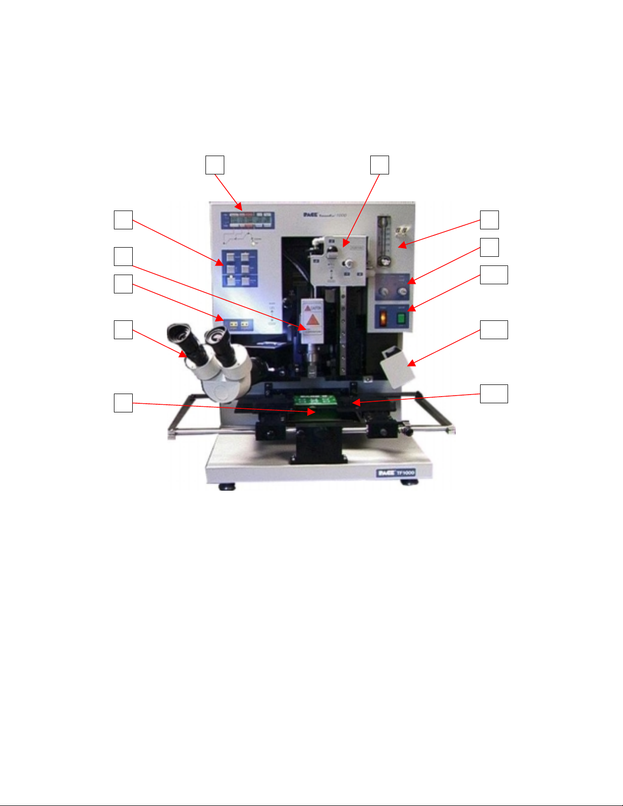
D. Structure
2345678
9
10
11
1
12
1. Infrared Bottom-Side heater
2. Microscope Optics
3. Thermocouple inputs 1 and 2
4. Top-Side Heater Assembly
5. Control Panel
6. LCD Display
7. Component Alignment/Placement apparatus
8. Airflow control/Indicator
9. PCB and Component light adjustment
10. Power and Vacuum On/Off switch
11. Cooling Fan
12. PCB Holder
5
Page 7
Operation Manual
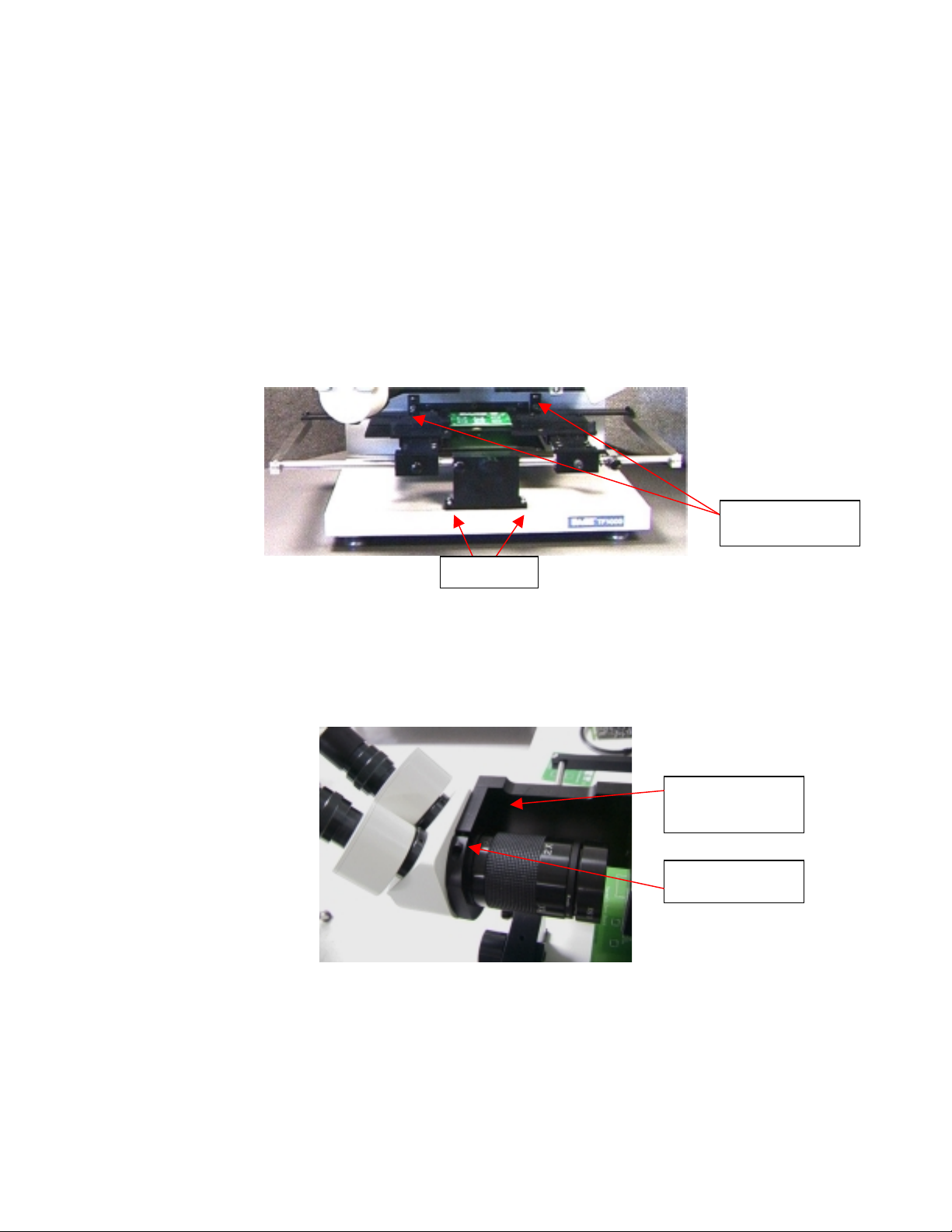
E. TF 1000 Setup
1. Place the T F 1000 on a flat and stable work surface.
2. Install the PCB Holder assembly by inserting the rear rail of the PCB
holder into the rolling guides on the TF 1000 housing and installing and
tightening the four screws shown in the figure below.
3. Insert the Microscope Optics into the Optics Holding Bracket and tighten
the Allen Screw after centering the Optics as shown below.
4 screws
Rolling Guides
Optics Holding
Bracket
Allen Screw
4. Connect the power cord to the AC power receptacle on the rear panel of
the TF 1000 and to the proper AC power source.
6
Page 8

F. Before Operation
1. Confirm the safety of the machine and the surrounding work area before
turning the power on.
2. The bottom heater will take approximately 5-6 minutes to warm up to the
desired temperature once power is applied. During this time the HEATER
START light will flicker on and off. Once the desired temperature is
reached the HEATER START light will remain lit, indicating the TF 1000 is
ready to use.
3. Confirm that components/devices mounted to the PCB do not exceed the
following height restrictions:
A. Top-side of PCB – 30 mm maximum height
B. Bottom-side of PCB – 15 mm maximum height
7
Page 9

G. Installing PCB
A
1. Loosen both (A) knobs to allow the PCB holders to glide freely in the X-
axis, and set the distance between them so that the spring loaded PCB
holder will hold the PCB firmly. T igh ten the (A) knob on the left first, and
then slide the spring-loaded PCB holder into position and tighten the (A)
knob on the right.
2. Pull back on the spring-loaded board holder and insert the PCB.
3. Once the PCB is in place, loosening knob (C) will allow the entire PCB to
glide freely in the X-axis using the fine adjustment job (D). The PCB will
also slide freely in the Y-axis. Tighten knob (C) to lock the PCB in place.
NOTE:
If profiling a PCB/Component and when using thermocouple(s), attach
the thermocouple(s) to the desired position on the PCB and plug them into the
Sensor 1 or 2 positions as shown below,
B B
C D
before
A (Spring Loaded)
inserting PCB into PCB holder.
Thermocouple Inputs
8
Page 10

H. Preparation for Component Rework
1. The reflow nozzle to PCB standoff height can be established prior to
component placement. Pull the Reflow Nozzle Control Handle out from the
housing and slide the Reflow Assembly down to the PCB as shown below.
Reflow
Nozzle
Control
Handle
2. Fine placement of the ref low nozzle down to the PCB can be achieved by
setting the Nozzle to PCB Offset Limiter and twisting the nozzle control
handle in either direction as shown below.
Start Finish
Nozzle to
PCB Offset
Limiter
3. The Reflow Nozzle can now be lowered gently to the PCB by twisting the
9
With the handle twisted so the
mechanics look like this…
Reflow Nozzle Control Handle back to the lowered position.
…the Reflow Nozzle will float
slightly off the PCB.
Page 11

I. Component Alignment
1. The TF 1000 has three positions for the alignment apparatus: Standby,
Alignment, and Placement. The positions are shown below.
2. The alignment apparatus is released by pulling the Z-Axis adjustment
Standby Alignment Placement
knob out as shown below.
Apparatus release
3. Bring the microscope into position by swinging the microscope into place.
Release the alignment apparatus from the standby position and slide it
down to the alignment position as shown above.
CAUTION:
Do not let the alignment apparatus drop freely to the position
below at any time. Damage to the TF 1000 or PCB may occur.
10
Page 12

4. Using the microscope, center the component pattern of the PCB in the
viewer as shown below. The crosshairs and focus are adjusted by turning
the eyepiece(s) on the microscope.
5. Center the vacuum pick so that it fills the viewer as shown below.
6. Press the “Vacuum On” button and attach the component to the vacuum
pick. Using the X, Y, and Theta adjustment knobs, align the component
over the PCB as shown below. Use the PCB/Device light adjustments to
increase or decrease the contrast as needed.
Misaligned Aligned
11
Page 13

J. Component Placement
1. Swing the Microscope out to the standby position. Release the alignment
apparatus and slide it down until the component gently touches the PCB
as shown below.
2. Press the “Vacuum Off” button to release the component onto the PCB.
3. Slide the alignment apparatus up to the standby position.
K. Component Reflow
1. Using the Reflow Nozzle Control Handle, pull the reflow assembly out from
the housing and slide it gently down to the PCB as shown below. Use the
Nozzle to PCB Offset Limiter if necessary.
Reflow
Nozzle
Control
Handle
Start Finish
12
Page 14

4. Select the desired profile using the LCD display. Push the Select button until
the flashing cursor is located under the “Profile No.” position and push the Up
and Down button until the desired profile number is displayed.
Cursor
LCD Display
5. Push the “Cycle Start” button to start the reflow process. If needed, lifting the
nozzle back up to the standby position will automatically stop the cycle at any
time.
6. The status indicator lo cated below the LCD display will track the reflow
process. Thermocouple readings are displayed at Sensor 1 and Sensor 2 as
shown below.
Status
Indicators
Thermocouple
Sensor Display
13
Page 15

7. Changes can be made during the reflow process by pressing the “Select”
button to move the cursor to the desired setting to be changed and then
pressing the Up/Down buttons until the desired setting is achieved.
Move
Cursor
Cycle
Start
Change
Setting
8. At the end of the reflow process, an audible tone will be heard and the
Reflow display will count down to 0. The cooling fan will activate
automatically and can be turned off by pressing the “Cooling Off” button.
Additionally, the angle of the fan can be adjusted so that the fan does not
blow towards the PCB/Component at all. This may be required for CBGA to
ensure the cooling process does not occur too rapidly.
9. The Reflow Nozzle assembly may now be returned to the standby position by
lifting the Reflow Nozzle Control Handle up and in. If performing component
removal, remove the component using the provided vacuum pick wand.
10. Pressing the “Memory” button twice will now save changes made to the
profile during the reflow process. To save the changed profile as a new
profile, press the “Memory” button once, select the profile number to save as,
then press the “Memory” button again. An audible tone verifies the profile
has been saved.
14
Page 16

L. Specifications
1. Heater (top-side)
2. Pre-heater (bottom-side) IR Heater, 450W (TF1000E 400W)
3. Heating Control K type thermocouple with closed loop control
4. Applicable Devices BGA/CSP/SMT 42mm x 42mm (1.65” x 1.65”) Max
5. Applicable PCB 280 mm x 450 mm (11” x 17.5”) Max
6. Hot Air Flow 16 LPM Max
7. Adjusting Range of X, Y, Z ± 10 mm (.4”)
8. Adjusting volume of X, Y, Z 0.5 mm (.02”) per revolution
9. Positioning Accuracy ± 25 µm (0.001”)
10. Maximum Vacuum 450 mm Hg
11. Power Source 100-120 VAC, 220-230 VAC (Export)
Convective style, 700 W
12. Power Consumption 1.1 KW
400 mm W x 400 mm L x 520mm H
13. Dimensions
14. Weight 25 Kg (55 lbs.)
15.74” W x 15.74” L x 20.47” H
15
Page 17

M. Accessories
Note:
for 1.5 mm clearance between the edge of the component and the nozzle wall.
Example: The 30mm x 30mm nozzle will fit a 27mm x 27mm component.
Note:
for CBGA. Other components are specified as listed.
Example: 27mm – 2 will fit a 27m m x 27mm PBGA
27mm – 4 will fit a 27mm x 27mm CBGA
Description Dimensions Part Number
Nozzle
Nozzle
Nozzle
Nozzle
Nozzle
Nozzle
Nozzle
Nozzle
Nozzle
Nozzle
Nozzle 30mm x 30 mm (1.18” x 1.18”) 4028-5027
Nozzle 27mm x 27mm (1.1” x 1.1”) 4028-5001
Nozzle 26.4mm x 26.4mm (1.04” x 1.04”) 4028-5026
Nozzle 25mm x 32.3mm (.98” x 1.27”) 4028-5028
Nozzle 25mm x 25mm (.99” x .99”) 4028-5011
Nozzle 23mm x 23mm (.91” x .91”) 4028-5002
Nozzle 22mm x 14mm (.87” x .55”) 4028-5023
Nozzle 21mm x 21mm (.83” x .83”) 4028-5016
Nozzle 19.25mm x 19.25mm (.76” x .76”) 4028-5024
Nozzle 19mm x 19mm (.75” x .75”) 4028-5019
Nozzle 18.5mm x 18.5mm (.73” x .73”) 4028-5025
Nozzle 17mm x 17mm (.67” x .67”) 4028-5015
Nozzle 16.25mm x 17.75mm (.64” x .70”) 4028-5006
Nozzle 16mm x 16mm (.63” x .63”) 4028-5022
Nozzle 15mm x 15mm (.59” x .59”) 4028-5005
Nozzle 13.45mm x 14.97mm (.53” x .59”) 4028-5007
Nozzle 13mm x 13mm (.51” x .51”) 4028-5004
Nozzle 11.97mm x 13.21mm (.47” x .52”) 4028-5009
Nozzle 10.42mm x 10.42mm (.41” x .41”) 4028-5008
Nozzle 8.64mm x 8.90mm (.34” x .35”) 4028-5010
Nozzle dimensions are the outside diameter of the nozzle. Please allow
Component Stenciling Tool Kits dimensions: - 2 are for PBGA and - 4 are
47.5mm x 47.5mm (1.87” x 1.87”)
44mm x 44mm (1.73” x 1.73”)
43mm x 43mm (1.69” x 1.69”)
42.5mm x 42.5mm (1.67” x 1.67”)
40mm x 40mm (1.57” x 1.57”)
37.5mm x 37.5mm (1.48” x 1.48”)
35mm x 35mm (1.38” x 1.38”)
33mm x 33mm (1.29” x 1.29”)
32mm x 32mm (1.26” x 1.26”)
31mm x 31mm (1.22” x 1.22”)
4028-5034
4028-5030
4028-5029
4028-5013
4028-5012
4028-5018
4028-5003
4028-5033
4028-5020
4028-5014
16
Page 18

Nozzle 7.75mm x 5.6mm (.31” x .22”) 4028-5501
Nozzle 4.1mm (0.16”) Jet Spacing x 6.1mm (0.24”) Jet Length 4028-4001
Nozzle 4.1mm (0.16”) Jet Spacing x 10.9mm (0.43”) Jet Length 4028-4002
Nozzle 7.9mm (0.31”) Jet Spacing x 10.9mm (0.43”) Jet Length 4028-4003
Nozzle 7.9mm (0.31”) Jet Spacing x 13.5mm (0.53”) Jet Length 4028-4004
Nozzle 7.9mm (0.31”) Jet Spacing x 16mm (0.63”) Jet Length 4028-4005
Nozzle 7.9mm (0.31”) Jet Spacing x 18.5mm (0.73”) Jet Length 4028-4006
Nozzle 11.68mm (0.46”) Jet Spacing x 20.83mm (0.82”) Jet Length 4028-4007
Nozzle 11.42mm (0.45”) Jet Spacing x 27.17mm (1.07”) Jet Length 4028-4008
Nozzle 18.6mm (0.73”) Jet Spacing x 12.8mm (0.50”) Jet Length 4028-4505
Nozzle 10.4mm (0.41”) Jet Spacing x 21.35mm (.84”) Jet Length 4028-4506
Component Stenciling Tool Kit, 40mm - 2 7016-0016
Component Stenciling Tool Kit, 35mm - 4 7016-0006
Component Stenciling Tool Kit, 35mm - 2 7016-0030
Component Stenciling Tool Kit, 33mm - 4
Component Stenciling Tool Kit, 31mm - 2
Component Stenciling Tool Kit, 31mm - 4
Component Stenciling Tool Kit, 27mm - 4 7016-0007
Component Stenciling Tool Kit, 27mm - 2 7016-0029
Component Stenciling Tool Kit, 25mm - 2 7016-0017
Component Stenciling Tool Kit, 25mm - 4 7016-0020
Component Stenciling Tool Kit, 23mm - 2 7016-0008
Component Stenciling Tool Kit, 23mm - 4 7016-0013
Component Stenciling Tool Kit, 17mm - 2 7016-0009
Component Stenciling Tool Kit, 17mm - 4 7016-0012
Component Stenciling Tool Kit, 15mm - 2 7016-0010
Component Stenciling Tool Kit, 15mm - 1 7016-0023
Component Stenciling Tool Kit, 13mm - 2 7016-0011
Component Stenciling Tool Kit, 13mm x 10mm 7016-0027
Component Stenciling Tool Kit, 12mm CSP 7016-0014
Component Stenciling Tool Kit, 11mm x 8mm CSP 7016-0015
Component Stenciling Tool Kit, 19mm 7016-0018
Component Stenciling Tool Kit, 19mm Socket 7016-0026
Component Stenciling Tool Kit, 16.5 x 8mm, CSP 7016-0019
Component Stenciling Tool Kit, 22mm x 14mm 7016-0022
Component Stenciling Tool Kit, 4mm LCC 7016-0024
Component Stenciling Tool Kit, 8mm x 10mm 7016-0031
Component Stenciling Tool Kit, PLCC 28 7016-0033
Component Stenciling Tool Kit, 9mm 7016-0034
Component Stenciling Tool Kit, 24mm - 4 7016-0035
Component Stenciling Tool Kit, 6mm 7016-0036
Stencil, 40mm x 503 1040-0503-P1
Stencil, 40mm x 432 1040-0432-P1
7016-0021
7016-0028
7016-0032
17
Page 19

Stencil, 35mm x 388 1035-0388-P1
Stencil, 35mm x 456 1035-0456-P1
Stencil, 35mm x 313 1035-0313-P1
Stencil, 35mm x 352 1035-0352-P1
Stencil, 35mm x 480 1035-0480-P1
Stencil, 33mm x 503 1033-0503-P1
Stencil, 31mm x 304 1031-0304-P1
Stencil, 31mm x 329 1031-0329-P1
Stencil, 27mm x 352 1027-0352-P1
Stencil, 27mm x 316 1027-0316-P1
Stencil, 27mm x 225 1027-0225-P1
Stencil, 27mm x 256 1027-0256-P1
Stencil, 27mm x 272 1027-0272-P1
Stencil, 27mm x 292 1027-0292-P1
Stencil, 27mm x 324 1027-0324-P1
Stencil, 27mm x 328 1027-0328-P1
Stencil, 27mm x 336 1027-0336-P1
Stencil, 23mm x 169 1023-0169-P1
Stencil, 23mm x 288 1023-0288-P1
Stencil, 23mm x 324 1023-0324-P1
Stencil, 23mm x 208 1023-0208-P1
Stencil, 23mm x 256 1023-0256-P1
Stencil, 23mm x 484 1023-0484-P1
Stencil, 17mm x 208 1017-0208-P1
Stencil, 17mm x 256 1017-0256-P1
Stencil, 15mm x 156 1015-0156-P1
Stencil, 15mm x 160 1015-0160-P1
Stencil, 15mm x 196 1015-0196-P1
Stencil, 15mm x 196 1015-0196-P1
Stencil, 13mm x 144 1013-0144-P1
Stencil, 13mm x 64 1013-0064-P1
Stencil, 12mm x 144 1012-0144-P1
Stencil, 12mm x 160 1012-0160-P1
Stencil, 11mmx 8 x 72 1011-0072-P1
Stencil, 25m x 357 1025-0357-P1
Stencil, 25mm x 360 1025-0360-P1
Stencil, 19m x 225 1023-0256-P1
Stencil, 19m x 52 1023-0052-P1
Stencil, 16.5 x 8 x 52 1016-0052-P1
Stencil, 14 x 22 x 119 1014-0119-P1
Stencil, 4mm x 24 1004-0024-P1
Stencil, 4mm x 28 1004-0028-P1
Stencil, 4mm x 24 1004-2024-P1
18
Page 20

Stencil, 8mm x 48 1008-0048-P1
Stencil, PLCC 28 1012-0028-P1
Stencil, 9mm x 56 1009-0056-P1
Stencil, 24mm x 241 1024-0241-P1
Stencil, 6mm x 40 1006-0040-P1
Hand Held Vacuum Pick, TF1000 1272-0005-P1
Flux Applicator Tool Kit 6993-0218
K-Type Thermo Couple (2) 1340-0174-P5
19
Page 21

N. Maintenance
The TF 1000 is designed to be basically maintenance free. However, the Top
Heater and consumable parts may need to be changed from time to time.
1. The Vacuum filter should be cleaned every three months. Remove the
cover on the side of the TF 1000 as shown below. Remove the filter from
the filter assembly and clean with mild soap and water. Let the filter dry
completely before reassembling.
2. The Top Heater is easily replaced. Unplug the TF 1000 from the power
source. Ensure the heater is cool. Remove the heater protection cover
and remove the four screws that retain the heater assembly. Pull the
heater assembly downwards to remove it from the socket and install the
new heater. Install the four retaining screws and the protection cover.
Filter Assembly Location Remove and clean filter
Remove 4
Screws
Remove 4
Screws
Heater Protection Cover Heater Assembly
20
 Loading...