

Page 1
Page 2

Page 3
Manufactured under license from Dolby Laboratories.
“Dolby” and the double-D symbol are trademarks of Dolby Laboratories.
This product incorporates copyright protection technology that is protected by
U.S. patents and other intellectual property rights. Use of this copyright protection
technology must be authorized by Macrovision, and is intended for home and
other limited pay-per-view uses only unless otherwise authorized by Macrovision.
Reverse engineering or disassembly is prohibited.
HDMI, the HDMI logo and High-Definition Multimedia Interface are trademarks
or registered trademarks of HDMI Licensing LLC.
Trademark of the DVB Digital Video Broadcasting Project (1991 to 1996)
Pace and are trademarks and/or registered trademarks of
Pace Micro Technology plc.
Other trademarks listed herein are the proper ty of their respective owners.
The model number, serial number and electrical rating of this
set-top are on a label on its base.
Copyright © 2007 Pace Micro Technology plc. All rights reserved.
CONTENTS
SAFETY INFORMATION .............................................................................................2
REAR PANEL ...................................................................................................................8
CONNECTING THE EQUIPMENT ........................................................................ 10
Connecting your TV to the AC power supply ................................................ 14
OPERATING YOUR SET-TOP ................................................................................... 15
Turning your set-top on and off ......................................................................... 15
Using your remote control ................................................................................. 16
Activating loopthrough for a DVD or similar equipment ............................16
Using the front-panel buttons ............................................................................17
Your set-top’s DVR functions ............................................................................. 18
Using an external hard disk ................................................................................ 19
Lightning storms ....................................................................................................19
Using RF bypass .....................................................................................................20
MAKING USER SETTINGS ....................................................................................... 21
About User Settings ............................................................................................. 21
About the TV Aspect Ratio ................................................................................. 22
About TV Display Capability (resolution settings) ......................................... 23
Auto Pillarbox ........................................................................................................ 26
Making Closed Caption settings ........................................................................28
Front Panel Settings .............................................................................................. 30
Restoring the factory default settings ..............................................................31
USING ZOOM ............................................................................................................. 33
USING THE SETUP MENUS .....................................................................................34
SOLVING PROBLEMS ................................................................................................ 35
TERMS AND CONDITIONS FOR USE OF SOFTWARE (“TERMS”) ........... 40
OPEN SOURCE LICENSES ....................................................................................... 42
1
Page 4
SAFETY INFORMATION
RISK OF ELE CTRIC SHOCK
DO NOT OPEN
CAUTION
RISQUE DE CH OC ELECTRIQU E
NE PAS OUVRI R
ATTENTION
This digital set-top has been manufactured and tested with your
safety in mind. However, improper use can result in potential
electric shock or fire hazards. To avoid defeating the safeguards that
have been built into your set-top, please observe the precautions
discussed in this document.
Warnings on your set-top
The lightning flash with arrowhead symbol, within a
triangle, is intended to alert you to the presence of
uninsulated “dangerous” voltages within your set-top’s
enclosure that may be of sufficient magnitude to
constitute a risk of electric shock to persons.
The exclamation point within a triangle is intended to
alert you to the presence of important instructions in
the literature accompanying your set-top.
Other warnings
To reduce the risk of electric shock, do not remove the cover of
your set-top. There are no user-serviceable parts inside it.
Do not perform any servicing unless you are qualified to do so.
refer all servicing to qualified ser vice personnel. servicing the set-
2
top yourself will invalidate the warranty.
To reduce the risk of fire or electric shock, do not expose this settop to rain or moisture.
On the rear panel of your set-top there is a tamper-evident label
that states ‘Warranty void if broken or removed’.
To avoid possible damage to the internal hard disk, do not pick up
or move your set-top while it is connected to the wall AC outlet. If
you want to move your set-top, first stop any recording, then turn off
your set-top and wait 60 seconds before disconnecting it. You should
handle your set-top carefully, as any damage you cause to the internal
hard disk (or any other component) will invalidate your warranty.
Installation
The installation of your set-top should be carried out by a qualified
installer and should conform to local codes.
Note to the installer
This reminder is provided to call the attention of the cable-TV-system
installer to Section 820-40 of the National Electrical Code (USA),
which provides guidelines for proper grounding and, in particular,
specifies that the cable ground shall be connected to the grounding
system of the building, as close to the point of cable entry as is practical.
Service address:
Pace Micro Technology (Support Services) Ltd.
3701 FAU Boulevard, Suite 200, Boca Raton
Florida, 33431, U.S.A.
Page 5

IMPORTANT SAFETY INSTRUCTIONS
Before you install or use the apparatus, you must read
and understand these Important Safety Instructions.
At all times when using the apparatus you must follow
these Important Safety Instructions to reduce the risk of
fire, electrical shock and injury to persons.
1. Read these instructions.
2. Keep these instructions.
3. Heed all warnings.
4. Follow all instructions.
5. Do not use this apparatus near water.
6. Clean only with dry cloth.
7. Do not block any ventilation openings. Install in accordance
with the manufacturer’s instructions.
8. Do not install near any heat sources such as radiators, heat
registers, stoves, or other apparatus (including amplifiers) that
produce heat.
9. Do not defeat the safety purpose of the polarized or groundingtype plug. A polarized plug has two blades with one wider than
the other. A grounding type plug has two blades and a third
grounding prong. The wide blade or the third prong are provided
for your safety. If the provided plug does not fit into the outlet,
consult an electrician for replacement of the obsolete outlet.
10. Protect the power cord from being walked on or pinched
particularly at plugs, convenience receptacles, and the point
where they exit from the apparatus.
11. Only use attachments/accessories specified by the
manufacturer.
12. Use only with the cart, stand, tripod, bracket, or table
specified by the manufacturer, or sold with the apparatus.
When a cart is used, use caution when moving the cart/
apparatus combination to avoid injury from tip-over.
13. Unplug this apparatus during lightning storms or when
unused for long periods of time.
14. Refer all servicing to qualified service personnel. Servicing is
required when the apparatus has been damaged in any way,
such as power-supply cord or plug is damaged, liquid has been
spilled or objects have fallen into the apparatus, the apparatus
has been exposed to rain or moisture, does not operate
normally, or has been dropped.
3
Page 6
SAFETY INFORMATION (cont.)
2 inches
2 inches2 inches
In addition to the Important Safety Instructions, please read the
Safety Information below.
Power sources
You must operate your set-top only from the type of power
source indicated on the marking label. If you are not sure of the
type of power supply to your home, consult your dealer or local
power company. If you move your set-top between locations at
different temperatures, allow it to reach room temperature before
you apply power to it.
Water and moisture
Do not expose your set-top to dripping or splashing and ensure
that no objects filled with liquids, such as vases, are placed on your
set-top. See also item 5 in the Important Safety Instructions.
Lightning
For added protection for your set-top during a lightning storm,
or when it is left unattended and unused for long periods of time,
disconnect the cable system from your set-top. See also item 13 in
the Important Safety Instructions.
Placement and mounting
Do not place your set-top on an unstable or uneven surface.
Your set-top may fall, causing serious injury to a child or adult and
serious damage to your set-top. If you mount your set-top, for
example to a wall or ceiling, follow the manufacturer’s instructions
and use a mounting accessory recommended by the manufacturer.
See also item 12 in the Important Safety Instructions.
4
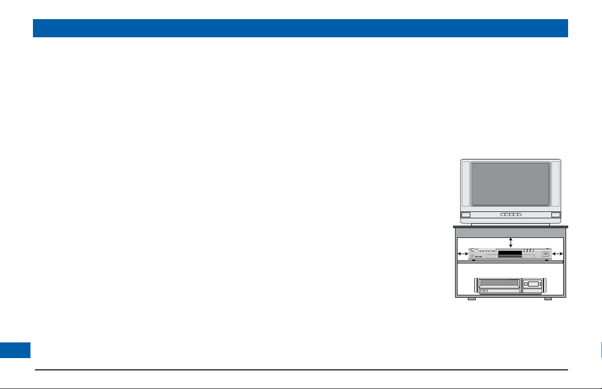
Ventilation
Slots and openings in the casing of your set-top are provided for
ventilation, to ensure reliable operation of your set-top and to
protect it from overheating.
• Never block the ventilation openings by placing your set-top on
a bed, sofa, rug or other similar surface.
• Never cover the ventilation openings with items such as
newspapers, table-cloths or curtains.
• Do not place your set-top
in a built-in installation such
as a bookcase or rack unless
proper ventilation is provided
or you have adhered to the
manufacturer’s instructions.
• It is recommended that you
maintain a minimum distance
of 2 inches around your settop for sufficient ventilation.
See also item 7 in the Important
Safety Instructions.
Entry of objects and liquids
Never push objects of any kind into your set-top through openings
as they may touch dangerous voltage points or short-out par ts that
could result in fire or electric shock. Never spill liquid of any kind
on your set-top.
Page 7
SAFETY INFORMATION (cont.)
electric service equipment
power service grounding electrode system
(NEC ART 250, PART H)
grounding conductors
(NEC section 810-21)
antenna-discharge unit
(NEC section 810-20)
antenna lead-in wire
ground clamps
ground clamps
Transporting
Move the combination of set-top and cart with care. Quick stops,
excessive force and uneven surfaces may cause the combination
of set-top and cart to overturn. See also item 12 in the Important
Safety Instructions.
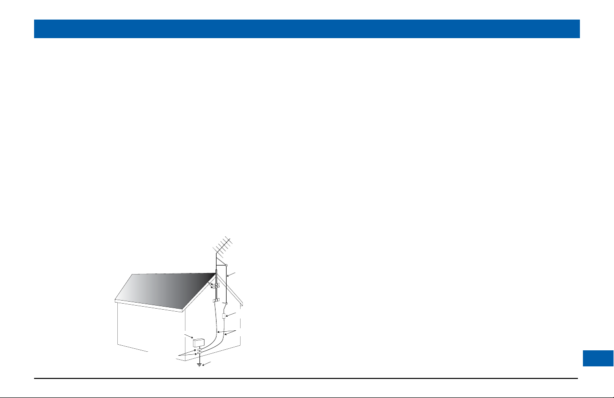
Outdoor antenna grounding
Be sure that any outside antenna or cable system connected
to your set-top is grounded so as to provide some protection
against voltage surges and static charges that have built up.
Article 810 of the National Electrical Code (USA), ANSI/NFPA
70 provides information with regard to proper grounding of the
mast and supporting structure, grounding of the lead-in wire to an
antenna-discharge unit, size of grounding conductors, location of
antenna-discharge unit, connection to grounding electrodes and
requirements for the grounding electrode. See the diagram below.
(Example antenna grounding as per
National Electrical Code, ANSI/NFPA 70)
Risk of fire or scorching
Never place naked flame sources, such as lighted candles, on or
adjacent to your set-top.
Ambient temperature
The operating temperature range of your set-top is 32-104°F. If the
ambient temperature around your set-top falls outside this range,
you must correct this in order for your set-top to work correctly
and safely. For example, if the temperature is too high, switch on
the air conditioning.
Overloading
Do not overload wall outlets, extension cords or other power
outlets as this can result in a risk of fire or electric shock.
Replacement parts
When replacement parts are required, be sure that the
service technician has used replacement parts specified by the
manufacturer or that have the same characteristics as the original
part. Unauthorized substitutions may result in fire, electric shock or
other hazards. See also item 14 in the Important Safety Instructions.
Safety check
Upon completion of any servicing or repairs to your set-top, ask
the service technician to perform safety checks to determine that
your set-top is in its proper operating condition. See also item 14
in the Important Safety Instructions.
SAVE THIS INFORMATION FOR FUTURE REFERENCE
5
Page 8
SAFETY INFORMATION (cont.)
Safety aspects of connections
Full details of the rear panel are on page 8.
Connecting
Do not connect your set-top (or any other equipment such as a TV
or VCR) to the power supply until you have properly connected all
the other cables.
Your set-top operates with a 120 V AC, 60 Hz power supply.
Do not connect your set-top to any supply other than this.
This set-top is equipped with a two-wire power cord, with a
polarized plug at one end. The other end of the cord is fitted with a
polarized connector, which is shaped such that it can be fitted only
one way into the power input jack of your set-top. Connect this
end first, before inserting the polarized plug into the wall socketoutlet.
Disconnecting
Disconnect your set-top from the power supply before you
disconnect any other equipment from its rear panel.
The only way to disconnect your set-top from the power supply
is to remove the power cord from the wall socket-outlet. Your
set-top must therefore be installed near to the wall socket-outlet,
which should be easily accessible.
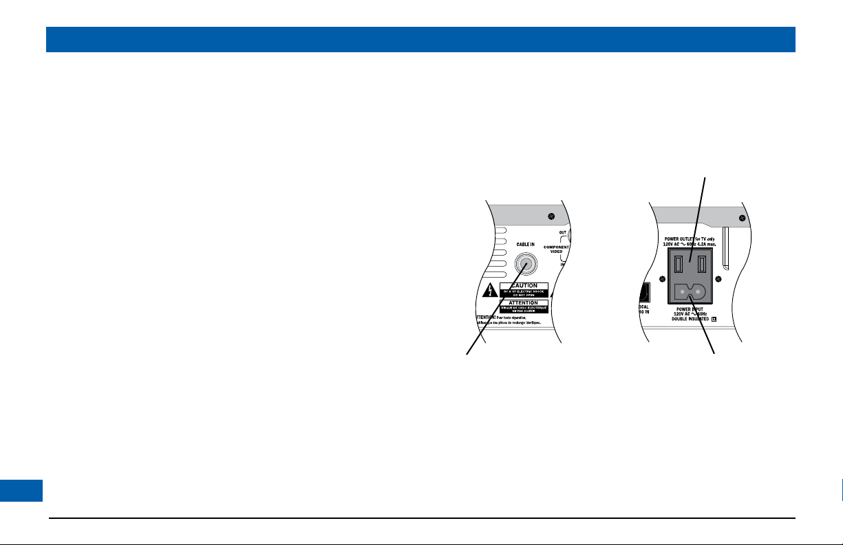
The POWER OUTLET plug is designed only for connection to the AC
power cord for a TV. The maximum power it can supply is 500 watts.
Do not connect any equipment that uses more than 500 watts, or
any non-TV equipment such as a toaster or hair dryer.
The CABLE IN connector is designed for
connection to a cable network only.
You must not connect any other equipment,
such as a VCR, to this input.
POWER INPUT
6
Page 9

SAFETY INFORMATION (cont.)
Epilepsy and on-screen images
Certain people are susceptible to epileptic seizures or losing
consciousness when faced with certain types of flashing lights in
our daily environment.
These people are exposed to the risk of seizures if they watch
certain television images or if they view certain images while they
are browsing the Web. These phenomena may appear even when
the subject has no previous history of this problem or has never
suffered an epileptic seizure.
If you, or a member of your family, has already suffered symptoms
linked to epilepsy (seizure or loss of consciousness) in the presence
of stimulation by light, please consult your doctor before using this
product.
If you or any person using the equipment experiences dizziness,
involuntary movements or convulsion, please immediately stop
viewing and consult a doctor.
When you are browsing the Web or playing a Web-based game,
take the following precautions:
• Use the equipment in a well-lit room, and turn down the
brightness of your television screen.
• Sit at a reasonable distance from your television screen.
• Take a break for ten minutes every hour.
You should avoid using the Web if you are tired or have lost some sleep.
Regulatory information
CAUTION: Do not attempt to modify your set-top without
written authorization from the manufacturer. Unauthorized
modification could void your authority to operate your set-top.
NOTE
Your set-top has been tested and found to comply with the limits for
a Class B digital device, pursuant to Part 15 of the FCC Rules. These
limits are designed to provide reasonable protection against harmful
interference in a residential installation. Your set-top generates, uses
and can radiate radio-frequency energy and, if not installed and used
in accordance with the instructions, may cause harmful interference to
radio communications.
However, there is no guarantee that interference will not occur in a
particular installation. If your set-top does cause harmful interference
to radio or television reception, which can be determined by turning
your set-top off and on, you are encouraged to try to correct the
interference by one or more of the following measures:
• Reorient or relocate the receiving antenna.
• Increase the separation between your set-top and the receiver.
• Connect your set-top to an outlet on a circuit different from that to
which the receiver is connected.
• Consult your dealer or an experienced radio/TV technician for help.
7
Page 10
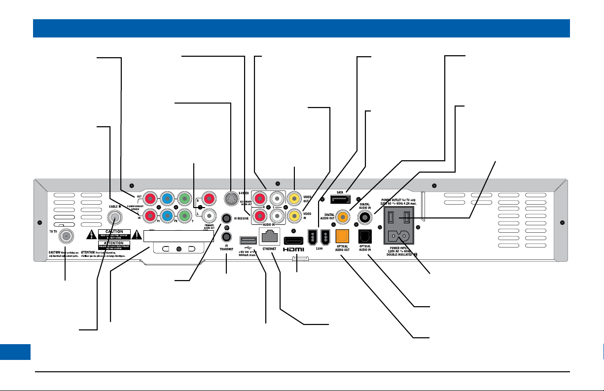
REAR PANEL
COMPONENT
VIDEO OUT
Component video output
for analog HDTV
COMPONENT
VIDEO IN
Component analog
video input
TO TV
RF output to the
TV or VCR
CABLE IN
From cable
service-provider
8
AUDIO IN
Audio inputs
(stereo, L and R)
S-VIDEO
S-video output
PRIMARY
AUDIO OUT
Audio outputs
(stereo, L and R)
IR RECEIVE
Infra-red input from
a remote “eye”
Separable security module
(behind cover)
Removal will interrupt your service
IR TRANSMIT
Infra-red output
to control a VCR
(for future use)
SECONDARY
AUDIO OUT
Audio outputs
(stereo, L and R)
VIDEO IN
Composite video
input
VIDEO OUT
Composite video
output
HDMI
Video and audio
output for digital HDTV
UNIVERSAL
SERIAL BUS (USB)
For future use
ETHERNET
For future use
1394
For connections to
1394-compatible
devices
SATA
For connection
to an external
hard disk
DIGITAL AUDIO OUT
Electrical S/PDIF audio output
DIGITAL AUDIO IN
Electrical S/PDIF audio input
POWER OUTLET
(500 W max.)
POWER INPUT
(Make this connection last of all)
OPTICAL AUDIO IN
Optical S/PDIF audio input
OPTICAL AUDIO OUT
Optical S/PDIF audio output
Page 11
REAR PANEL (cont.)
CABLE IN Connect the cable service here.
TO TV Connect to the RF/antenna input on your TV or
VCR (optional).
COMPONENT
VIDEO OUT
COMPONENT
VIDEO IN
Separable security
module
(behind cover)
PRIMARY AUDIO
OUT
IR TRANSMIT Connect to an optional VCR controller (future use).
IR RECEIVE Connect to an optional remote “eye”.
S-VIDEO Connect to the S-video input (if present) on your
SECONDARY
AUDIO OUT
AUDIO IN Connect to the L and R audio outputs on your
VIDEO OUT Connect to the video composite input on your
VIDEO IN Connect to the video composite output on your
If your HDTV does not have an HDMI (see
below), connect your HDTV here.
Connect equipment such as a DVD player, if it
has component video jacks.
Removal will interrupt your service.
Connect to the L and R audio inputs on your
stereo TV, stereo VCR or optional stereo amplifier.
VCR or TV.
Connect to the L and R audio inputs on your
secondary TV, VCR or optional stereo amplifier.
DVD player (or similar).
VCR (or a standard TV).
VCR (or a standard TV).
USB
(Universal Serial
Bus)
ETHERNET Connect to an optional PC network (future use).
HDMI
(High Definition
Multimedia
Interface)
1394 Connect to 1394-compatible devices.
SATA Connect to an optional external hard disk.
DIGITAL AUDIO
OUT
OPTICAL AUDIO
OUT
DIGITAL AUDIO INConnect to any electrical digital audio output
OPTICAL AUDIO INConnect to any optical digital audio output that
POWER OUTLET Connect your TV’s power cord here to provide
POWER INPUT Connect your set-top’s power cord here.
Connect to compatible optional equipment that
supports a USB 2.0 interface (future use).
If your HDTV has an HDMI, connect it here for
a digital audio/video connection (instead of
using the AUDIO and 3 analog COMPONENT
VIDEO connectors).
Connect to the electrical digital audio input on
optional digital audio equipment, such as an audio
decoder or home theater receiver.
Connect to the optical digital audio input on
optional digital audio equipment.
that loops through your set-top.
loops through your set-top.
AC power to your TV.
9
Page 12

CONNECTING THE EQUIPMENT
Your set-top fully complies with international DVB (Digital Video Broadcasting)
standards. In order for you to view programs broadcast in high-definition, your settop must be connected to a suitable HDTV or computer monitor. Your set-top is also
compatible with standard-definition TVs and VCRs.
Your equipment should have been connected up by your installer. However, if you
need to disconnect and re-connect your equipment, please read pages 10 to 14.
On pages 12 and 13 there are two typical connection set-ups for an HDTV, VCR,
DVD player and home theater receiver.
These set-ups make efficient use of the connectors on your set-top. However,
depending on your other equipment and the connectors on it, the person who
installed your system may have chosen to connect things up differently.
Both set-ups allow stereo recording and play-back of video tapes. You hear stereo
sound from the home theater’s loudspeakers.
Although the RF cables (shown by dashed lines in the diagrams) are not absolutely
necessary, we recommend that you connect them as a back-up and so that you can
use the RF bypass. If you use the RF cables, you must tune our TV (and VCR) to your
set-top’s VHF output channel (3 or 4: consult your cable service-provider to find
which channel it is for your location). Consult the manuals supplied with your TV and
VCR for information on how to tune.
You can take advantage of the digital audio output from your set-top by connecting a
suitable cable between your home theater receiver and the OPTICAL AUDIO OUT
jack (as shown in the diagrams) or the DIGITAL AUDIO OUT jack.
10
WARNINGS
Do not connect your set-top (or any other
equipment such as a TV or VCR) to the AC power
supply until you have properly connected all the
other cables.
Disconnect your set-top from the AC power
supply before you disconnect any other
equipment from its rear panel.
The only way to disconnect your set-top from
the AC power supply is to remove the AC power
cord (or switch the wall socket-outlet switch, if
present, to its OFF position). Your set-top must
therefore be installed near to the AC power
socket-outlet, which should be easily accessible.
The power outlet is designed only for connection
to the AC power cord for a TV. The maximum
power it can supply is 500 watts. Do not connect
any equipment that uses more than 500 watts, or
any non-TV equipment such as a toaster or hair
dryer.
The cable input is designed for connection to a
cable network only. You must not connect any
other equipment, such as a VCR, to this input.
Any cable connected to DIGITAL AUDIO jacks
must be 75 ohm coaxial, not regular audio cable.
Page 13
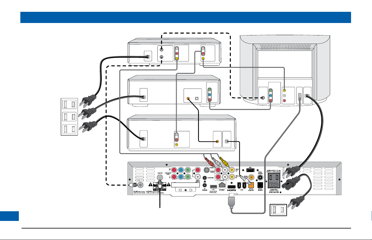
CONNECTING THE EQUIPMENT (cont.)
Set-up A - Home theater system with HDTV
(HDMI connection)
Set-up A (see page 12) uses an HDMI (high definition multimedia interface) connector to connect
to the HDTV. This displays the highest quality picture on the HDTV and also means there will be no
picture degradation on any future copy-protected programs (provided the link remains secure – see
right).
Variation
S-video provides a better TV picture than composite video, therefore, if your TV and VCR have
S-video connectors, replace the composite video connection with an S-video connection to your
VCR, then connect directly via an S-video connection from your VCR to your TV (or loop through
your home theater receiver if you prefer).
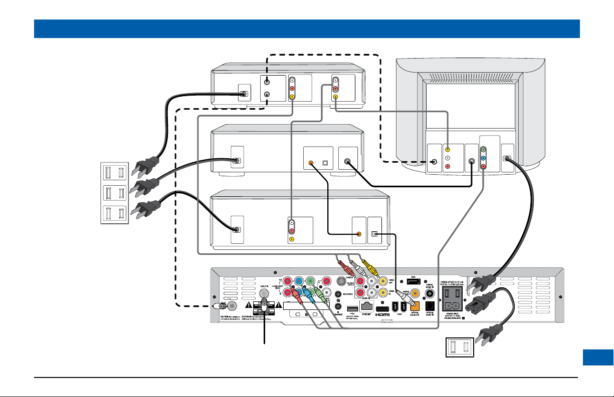
Set-up B - Home theater system with HDTV
(Component video / YPbPr connection)
Set-up B (see page 13) uses a component video connection to connect to the HDTV. This displays a
high definition picture on your TV.
NOTE
How you set up your equipment may depend on your home theater receiver. For example, the optical
and digital audio inputs may be associated with particular video inputs. Please see your home theater user
information for further details.
NOTE
Copy protection via HDMI
secure link
The HDMI link between your settop and your TV/monitor should
be a secure link. When your settop is attached via a HDMI cable
to an HDCP (High-bandwidth
Digital Content Protection)
-compliant monitor, the monitor
and set-top negotiate a secure
link, which allows your set-top
to transmit full resolution video
(picture) to your TV/monitor.
Not all monitors support HDCP.
If your set-top is connected to a
monitor that does not support
HDCP, the following is displayed:
Your HDTV does not support HDCP.
Please use the YPbPr component
connection to watch TV.
The HDMI output is then disabled,
so no picture is transmitted from
this connector. In that case use the
component video connectors to
connect up (see Set-up B).
11
Page 14
CONNECTING THE EQUIPMENT (cont.)
ANTENNA/
RF IN
TV / RF
OUT
ANTENNA/
RF IN
LEFT
AUDIO IN
RIGHT
AUDIO IN
VIDEO IN
LEFT
AUDIO IN
RIGHT
AUDIO IN
VIDEO IN
POWER
LEFT
AUDIO OUT
RIGHT
AUDIO OUT
VIDEO OUT
CABLE INPUT
HDTV
VCR
DVD
LEFT
AUDIO IN
VCR IN
RIGHT
AUDIO IN
VIDEO IN
PB/CB
PR/CR
Y
COMPONENT
VIDEO OUT
HOME THEATER RECEIVER
OPTICAL
AUDIO IN
COAXIAL
AUDIO IN
DIGITAL AUDIO OUT
DIGITAL AUDIO IN
OPTICAL COAXIAL
PB/CB IN
PR/CR IN
Y IN
COMPONENT
VIDEO IN
POWER
POWER
POWER
HDMI
WALL AC OUTLET
WALL AC OUTLETS
Set-up A
12
Page 15
ANTENNA/
RF IN
TV / RF
OUT
ANTENNA/
RF IN
LEFT
AUDIO IN
RIGHT
AUDIO IN
VIDEO IN
LEFT
AUDIO IN
RIGHT
AUDIO IN
VIDEO IN
POWER
LEFT
AUDIO OUT
RIGHT
AUDIO OUT
VIDEO OUT
CABLE INPUT
HDTV
VCR
DVD
LEFT
AUDIO IN
VCR IN
RIGHT
AUDIO IN
VIDEO IN
HOME THEATER RECEIVER
OPTICAL
AUDIO IN
COAXIAL
AUDIO IN
DIGITAL AUDIO OUT
DIGITAL AUDIO IN
OPTICAL COAXIAL
POWER
POWER
POWER
WALL AC OUTLET
WALL AC OUTLETS
PB/CB IN
PR/CR IN
Y IN
COMPONENT
VIDEO IN
S-VIDEO OUT
S-VIDEO
IN
Set-up B
CONNECTING THE EQUIPMENT (cont.)
13
Page 16
CONNECTING THE EQUIPMENT (cont.)
WARNINGS
Do not connect your set-top (or any other equipment such as a TV or VCR) to the AC power supply until
you have properly connected all the other cables.
Do not defeat the safety purpose of the polarized plugs on power cords. A polarized plug has two blades
with one wider than the other. This plug fits into the outlet in only one way; match the wide blade of the
plug to the wide slot of the outlet.
Connecting your TV to the AC power supply
If your TV has a rating of less than 500 W, connect the power cord from your TV into the connector
labeled “POWER OUTLET” on the rear panel of your set-top. This saves a wall outlet (although, if
your TV is rated 500 W or more, you must connect it to a wall outlet).
Connecting the power cord to your set-top
Before you connect your set-top to a wall outlet, connect the polarized socket on the power cord
into the plug labeled “POWER INPUT” on your set-top’s rear panel.
Connecting equipment to the wall AC outlets
Connect the polarized plugs on the power cords from your set-top, VCR and any other equipment
into wall AC outlets. If these outlets have switches, switch them to ON.
14
Page 17
OPERATING YOUR SET-TOP
Turning your set-top on and off
After you have connected your set-top to the wall AC outlet (and switched this outlet ON, if it has a
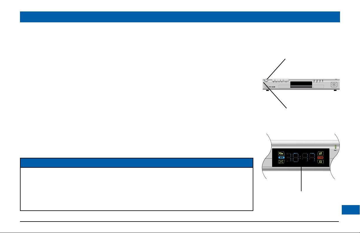
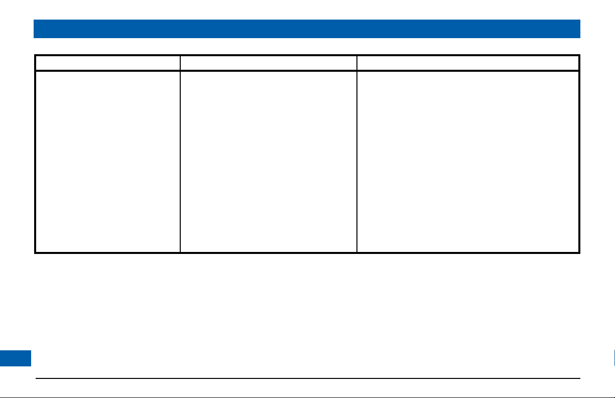
switch), the light next to the power button on your set-top’s front panel should be red.
Wait for a few seconds, then press the button labeled power on the front panel of your set-top to
turn it on. The light next to the power button goes from red to blue, to show that your set-top is
on.
If the light next to the power button is neither red nor blue, there is a problem.
To turn your set-top on or off at any time, press the power button on its front panel or the
POWER button on your remote control (first making sure your remote control is set to control
your set-top).
Never turn off your set-top by simply disconnecting it from the power supply. If you need to
disconnect your set-top, first stop any recording. Then turn off the set-top by pressing the power
button on its front panel or on your remote control, so that the light by the power button goes red.
Then wait 60 seconds before disconnecting your set-top at the wall AC outlet.
NOTES
It is important that, unless there is a lightning storm or you will be away from your home for a long time,
you do not unplug your set-top at the wall AC outlet (or do not switch it off there, if the outlet has a
switch). Your set-top cannot be updated with new features, through the cable, if it is disconnected from the
AC power supply.
Depending on your set-top’s settings, if you switch your set-top off, any TV that is attached to your settop’s POWER OUTLET may also turn off. For more details, see page 34.
To turn on your set-top,
press the power button.
The light next to the
button changes from
red to blue.
Front panel display, showing
the time (see page 34)
15
Page 18

OPERATING YOUR SET-TOP (cont.)
Using your remote control
Your cable TV service-provider determines the digital channels, services and screen information that
you see on your TV when you use your set-top and its remote control.
Consult the information supplied by your cable service-provider for details on how to make the
most of the digital cable services. Also read the operating instructions that are supplied with your
remote control.
Activating loopthrough for a DVD or similar
equipment
If you activate loopthrough, your set-top loops the inputs on its rear panel to the outputs as shown
in the table below. You need to do this if you have connected a DVD player or similar equipment and
wish to watch it on your TV.
COMPONENT VIDEO IN loops through to COMPONENT VIDEO OUT
VIDEO IN loops through to VIDEO OUT
AUDIO IN loops through to PRIMARY AUDIO OUT and
SECONDARY AUDIO OUT
DIGITAL AUDIO IN loops through to DIGITAL AUDIO OUT
OPTICAL AUDIO IN loops through to OPTICAL AUDIO OUT
To activate loopthrough, simply turn off your set-top by pressing the POWER button on your
remote (first making sure your remote control is set to control your set-top) or by pressing the
power button on the front panel. When your set-top is turned off, the light next to the power
button is red.
16
NOTE
Depending on your set-top’s
settings, if you put turn off your
set-top, any TV that is attached to
your set-top’s POWER OUTLET
may also turn off. For more
details, see page 34.
Page 19

OPERATING YOUR SET-TOP (cont.)
Using the front-panel buttons
You can use the buttons on the front panel to operate your set-top, if, for example, there is a problem with your remote control.
guide
To display an on-screen guide
bypass
To turn the RF bypass feature on/off
menu
To display on-screen menus
info
To display on-screen information
channel U and D
To change channel
up or down
front-panel display
Appears when your set-top
is turned on
Shows the program channel
number or the time
Also displays HDTV settings
(see page 21)
play/record lights
Indicate the play or record
state of each display channel
Lights green to signify
playback; lights red to signify
record
L, R, U and D
To move left/right/
up/down in an onscreen menu/guide
select button
To select items in
menus/guides
power button
To turn your set-top on/off
power light (next to button)
Lights blue when your set-top is
on; red when your set-top is off;
not lighted when your set-top is
disconnected from the power supply
Lights when your set-top is receiving a signal
from your remote control
Lights when your set-top outputs High
Definition Television (HDTV) content
Lights when your set-top receives
multi-channel sound
Lights when there is an unread message
Lights while the bypass feature is on
Lights if the current program has a
special broadcast security flag
VIDEO IN;
AUDIO IN L and R
(behind push panel)
RCA inputs
USB connector
– for future use
17
Page 20

OPERATING YOUR SET-TOP (cont.)
Using your set-top’s DVR functions
Your set-top has an internal hard disk that you can use to record and play back television programs,
giving you much more control of your viewing experience. For example, you can pause live television
and resume viewing from the point at which you left off. You can record many more hours than you
can by using a VCR or DVD recorder. There are lights on your set-top’s front panel to show when
recording and play-back are taking place. With your set-top you can:
• Pause live TV
• Instantly replay live TV
• Fast forward up to the point of live TV
• Watch a scene in slow motion
• Rewind through a program you have been watching
• Record high definition digital pictures (as well as the regular standard definition)
• Record one program while watching another
• Record two programs while watching a previously recorded program
• Schedule your set-top to record a program or a whole series
• Fully manage your stored recordings
• Back up your digital recordings to a VCR or DVD recorder
• Retain full control over any parental viewing restrictions you have set up
You control your set-top’s DVR functions using your remote control; consult the information supplied
by your cable service-provider for more details. Also read the operating instructions that are supplied
with your remote control.
18
NOTE
The exact functionality of the
DVR (digital video recorder)
in your set-top depends on
your on-screen program guide.
For more details, consult the
information supplied by your
cable service-provider.
Do not confuse recording to the
hard disk with recording to a
separate VCR or DVD recorder,
as mentioned on page 20.
Page 21

OPERATING YOUR SET-TOP (cont.)
Formatting the Hard
drive. Please
wait...
Do you want to format the
external hard drive?
YES
NO
Using an external hard disk
Your cable service-provider may enable a feature that allows an external hard disk to work with your
set-top. If this is the case, most major brands of serial ATA hard disk, connected to the SATA port, are
supported. You should not connect an external hard disk to a 1394 por t or a USB port.
If you do use an external hard disk, it gives extra recording capacity, but you cannot choose which
disk (internal or external) your set-top will record to. It will automatically choose the one with the
most empty space. The recordings on the external hard disk are uniquely linked to the set-top on
which they were made, so you cannot play them back or delete them with a different set-top.
Connecting an external hard disk
First stop any recording you are making to your set-top’s internal hard disk.
Turn off your set-top with the power button and then wait 60 seconds before disconnecting it from
the wall AC socket. (You must not “hot plug” an external hard disk).
Connect the external hard disk, using an appropriate cable, to the SATA connector on your set-top.
Apply power to the external hard disk.
Reconnect your set-top to the wall AC socket and turn it on with the power button.
If the external disk needs formatting, your set-top will do this automatically and inform you by means of
a pop-up dialog box on your TV screen (see right).
Lightning storms
Disconnect your set-top’s power cord during lightning storms. A lightning storm may affect your settop, if it is on during the storm. It may appear that it has stopped working, but you can easily restore
its operation as follows. Unplug your set-top’s power cord at the wall AC outlet. Then plug this power
cord in again at the wall AC outlet (and, if there is a switch by this outlet, switch it to its ON position).
Message for a new external hard disk
Message if the external hard disk has
previously been formatted on a PC.
Use the arrow and select buttons to
choose.
19
Page 22

OPERATING YOUR SET-TOP (cont.)
Using RF bypass
You can use RF Bypass to watch the regular (analog) channels that are included in the cable service.
It makes these channels “bypass” your set-top and pass directly to your TV and/or VCR.
To use RF Bypass:
• Your set-top must be installed with the correct connections from the rear panel to your TV or
VCR (see the note, right); and
• The RF Bypass feature must be switched to “On” in the Setup menu (see page 34).
Each time you want to use RF Bypass, you then press the BYPASS button on your set-top’s front
panel. The word BYPASS lights up on the front panel of your set-top. When you have finished using
RF Bypass, press the BYPASS button again.
For you to start using RF Bypass, your set-top must be turned on. However, once set, RF Bypass will
work even if you turn your set-top off.
When RF Bypass is on: you can use your TV’s remote control to tune to any of the available regular
(analog) channels and watch that channel on your TV (the path is the RF cable). You can, at the
same time, use your set-top’s composite video and L & R audio outputs to record on your VCR the
channel that your set-top is tuned to. (This channel number is shown on your set-top’s front panel.*)
This means that, when the bypass is on, you can watch a regular (analog) channel on your TV and, at
the same time, record a different channel on your VCR. (If you are recording to the hard disk, you can
record two different programs to it, while watching an analog channel on the bypass.)
When RF Bypass is off: you see on your TV the channel that your set-top is tuned to. This is the same
channel that your VCR receives. So, when RF Bypass is off, you can record on your VCR only the
program that you are watching on your TV (but you can still record a different one to the hard disk).
20
NOTE
If you are not sure whether your
set-top has been set up to allow
RF bypass, check your installation.
If there is a cable (RF cable)
going from the TO TV connector
on your set-top’s rear panel to
your TV (or to your VCR and
TV, as shown by the dashed line
on pages 12 and 13) then RF
bypass is correctly set up. Your
TV and VCR also need to have
been tuned to your set-top’s VHF
output channel (3 or 4, depending
on your location).
NOTE
* If the “Front LED Display” (see
page 34) is set to “Current Time”,
you will not see the channel
number. To see the number of
the channel your set-top is tuned
to, you should set “Front LED
Display” to “Current Channel”.
Page 23

About User Settings
USER SETTINGS
TV Aspect Ratio
TV Display Capability
Auto Pillarbox
Closed Captions
Front Panel Settings
Restore Defaults
Your installer should have made the correct settings to make sure your set-top is compatible with
your HDTV or TV. However you may wish to change some settings, for example if you purchase a
new HDTV. You can make the following settings.
• TV Aspect Ratio (the screen’s width-to-height ratio, or shape)
• TV Display Capability (screen resolution)
• Auto Pillarbox
• Closed Captions
• Front Panel Settings
You can also reset the user settings to the factory defaults.
You use the L, R, U, D and select buttons on either the front panel or your remote control to make
the settings. You check and change the settings by looking at your set-top’s front panel. You can also
look at the on-screen menus, although please note, in some circumstances, these may not be visible.
Putting your set-top into “user settings mode”
1. Make sure that your set-top is turned on.
2. Press the power button on your set-top, then, within 1 second, press the
menu button.
The front panel displays “ASPt” as shown far right. Depending on the set-up, you
may also see the User Settings menu, shown right, on your TV screen.
3. When you have finished making changes (see pages 22 to 30), press the power
button to remove the User Settings menu and return to normal viewing.
MAKING USER SETTINGS
power button.
menu button front-panel display
21
Page 24

TV Aspect Ratio
4:3
16:9
MAKING USER SETTINGS (cont.)
About the TV Aspect Ratio
The TV that you have connected to your set-top has an aspect ratio (width-to-height ratio) of 4:3
(basic/standard) or 16:9 (widescreen). You must set the appropriate TV Aspect Ratio (4:3 or 16:9) on
your set-top, so that it is compatible with your TV.
Setting the TV Aspect Ratio
If you have not done so, put your set-top into “user settings mode”, as described on page 21. The
front panel displays “ASPt”.
The flow diagram on the far right shows how you use the arrow and select buttons on your set-
top’s front panel to change the display and make the settings. See also the instructions below.
1. To change the
Aspect Ratio (4:3 or 16:9) appears on the front panel. Depending on the
set-up, you may also see the menu, shown right, on your TV screen.
2. Press the U or D button to choose the TV Aspect Ratio you want.
3. Press the select button to confirm the choice and change to that TV
Aspect Ratio.
4. Press the L button. The front panel will display “ASPt” again.
5. To continue making the settings, see the next section.
22
TV Aspect Ratio, press the R button. The current TV
4:3 standard TV,
EDTV or HDTV
16:9 HDTV
Page 25

MAKING USER SETTINGS (cont.)
About TV Display Capability (resolution settings)
• Your set-top can transmit pictures to your TV in a range of resolutions (also called “Display
Capabilities” - see below for the settings available). Generally, higher screen resolutions give better
quality pictures. However, the quality will always depend on how the program was originally
transmitted.
• Different TVs display different screen resolutions. For example, standard TVs display “480i”, EDTVs
(Enhanced Definition TVs) display “480p” and most HDTVs display “1080i” or “720p”. Many
HDTVs will display at more than one resolution. For more information, see the information
supplied with your HDTV.
You must make the appropriate TV Display Capability setting(s) on your set-top, so that it is
compatible with your TV. See the next page for full instructions.
In order to display the best picture every time, you should select every resolution that your TV is
capable of displaying. This should ensure that programs are displayed with the minimum distortion.
TV Display Capability settings
• 480i is standard definition NTSC and is
transmitted in a 4:3 aspect ratio (see right)
• 480p is enhanced digital TV and can be
transmitted in either a 4:3 or 16:9 aspect ratio
•
720p and 1080i are HDTV and are
transmitted in a 16:9 aspect ratio (see right)
480i transmission:
The aspect ratio is 4:3
1080i transmission:
The aspect ratio is 16:9
NOTE
When your HDTV is connected
to your set-top via an HDMI, your
set-top gets information from
your HDTV about the HDTV’s
display capability. Your set-top uses
this information to adjust its TV
Display Capability settings.
Your set-top also records your
HDTV’s ID (identification), so that
only one HDTV is supported at any
one time. When your HDTV has
updated your set-top’s TV Display
Capability settings, you may change
them if you wish. Your changes will
then be stored with the ID.
You can restore your set-top’s
TV Display Capability settings to
their factory values, as described
on page 31. You can also restore
your set-top to the settings that
your HDTV has passed to your
set-top. To do this you must first
restore the factory settings while
your set-top is disconnected from
your HDTV, then reconnect your
HDTV via an HDMI cable.
23
Page 26

TV Display Capability
1080i : YES
720p : NO
480p : YES
480i : YES
1080i
Yes
No
MAKING USER SETTINGS (cont.)
Changing the TV Display Capability
If you have not done so already, put your set-top into “user settings mode”, as described on page 21.
The front panel displays “ASPt”.
The flow diagram on page 25 shows how you use the arrow and select buttons on your set-top’s
front panel to change the display and make the settings. See also the instructions below.
1. To change the
TV Display Capability press the D button. The front
panel displays “res” (short for “resolution”), as shown in the flow diagram.
2. Press the R button. The first TV Display Capability resolution appears on
the front panel (1080i, although it is displayed as 1080). Depending on
the set-up, you may also see the TV Display Capability menu, shown right,
on your TV screen.
3. To check the resolution’s setting, press the R button. * Either “yes”
(selected) or “no” (not selected) is displayed. If you can see the onscreen menus, the menu shown right appears.
- If this is the correct setting, press the L button. The front panel will
display “1080” again.
- If you want to change the setting, press
U or D. (On the on-screen menu, the highlight moves
between the available settings). Press the select button to confirm your choice and change to
the new setting. Then press the L button. The front panel displays “1080” again.
4. Press U or D to display each resolution in turn, and repeat step 3 for each. The available resolutions
are: 1080i, 720p, 480p and 480i. (See pages 23 and 25 for more information about these).
5. When you are satisfied that all the TV resolutions are correct, press the L button. The front panel
24
displays “res” again. To continue making the settings, see page 26.
NOTE
*If you use the select button at
step 3, it will change the setting. If
you accidentally press the select
button, and the menus disappear
from your screen, immediately
press the select button again to
restore the menus.
Page 27

MAKING USER SETTINGS (cont.)
Further information about the TV Display Capability
The TV Display Capability settings relate to equipment that is connected to the HDMI and
COMPONENT VIDEO OUT connectors because the settings control the output at those
connectors. If equipment is connected via a HDMI cable, that equipment may also pass information
back to your set-top, which may affect what settings are available.
Generally, the TV Display Capability settings do not affect equipment connected to the VIDEO OUT
and S-VIDEO jacks, because the output at these jacks will always be the standard definition 480i.
This diagram shows an example only.
Please make sure that, for each
resolution, you select the correct
setting (yes or no) that applies to
your TV.
25
Page 28

4:3 transmission 16:9 TV with no automatic
detection of 4:3,
Auto-pillarbox switched off
16:9 TV with no automatic
detection of 4:3,
Auto-pillarbox switched on
MAKING USER SETTINGS (cont.)
Auto Pillarbox
If your TV is a 16:9 TV that does not automatically detect 4:3 transmissions (and therefore does
not add black bars to the sides of the picture), then 4:3 transmissions may display “stretched” to fit
the 16:9 screen. If you do not want this effect, you can set your set-top to add black bars to the 4:3
picture, so that it is transmitted to your TV at a 16:9 aspect ratio. See the example below.
Changing the Auto Pillarbox setting
If you have not done so already, put your set-top into “user settings mode”, as described on page 21.
The front panel displays “ASPt”.
1. To change the Auto Pillarbox setting, press the D button until the front panel displays “PiLL”, as
shown right.
26
Page 29

MAKING USER SETTINGS (cont.)
4:3 transmission
16:9 TV with no automatic
detection of 4:3,
Auto-pillarbox switched off
16:9 TV with no automatic
detection of 4:3,
Auto-pillarbox switched on
Use 'Zoom' to increase the picture size.
(Note: the picture may lose some
definition due to the expansion)
Auto Pillarbox?
YES
NO
2. Press the R button. Either “yes” (switched on) or “no” (switched off) is displayed. If you can see
the on-screen menus, the menu shown right appears.
3. If you want to change the setting, press U or D. Press the select button to confirm the choice
and change to the new setting.
4. Press the L button. The front panel displays “PiLL” again.
To continue making the settings, see the next section.
NOTE
16:9 picture in a 4:3 transmission
Sometimes 4:3 transmissions may contain a 16:9 picture, with black borders at the top and bottom. On a
16:9 TV this may display with black borders all the way around the picture. To remove these borders, you
can use the “Zoom” button on your remote control. See the example below. For more information about
using Zoom, see page 33.
27
Page 30

Closed Captions
CC : OFF
Configure Captions
MAKING USER SETTINGS (cont.)
Making Closed Caption settings
Closed captioning is a means of displaying alerts and subtitles on your TV screen, superimposed on
whatever you are watching. You can turn closed captions on or off, as required, and you can also
change the closed captions’ appearance.
Turning closed captions on or off
If you have not done so already, put your set-top into “user settings mode”, as described on page 21.
The front panel displays “ASPt”.
1. To change the Closed Captions setting, press the D button until the front panel displays “CC”, as
shown right.
2. Press the R button. Either “On” (switched on) or “OFF” (switched off) is displayed. If you can see
the menus, the Closed Captions menu appears, see right.
3. If you want to change the setting, press the select button - the setting changes.
4. Press the L button. The front panel displays “CC” again.
To continue making the settings, see the next section.
28
Page 31

USER SETTINGS
TV Aspect Ratio
TV Display Capability
Auto Pillarbox
Closed Captions
Front Panel Settings
Restore Defaults
Closed Captions
CC : ON
Configure Captions
Configure Captions
Size : Small
Font : Style 1
Character Color : White
Character Shading : Auto
Background Color : Black
Background Shading : Auto
Std Def CC : CC1
Hi Def CC : Digital 1
Caption Style : Viewer
Reset to Defaults
Closed Caption Example
MAKING USER SETTINGS (cont.)
Changing the closed captions’ appearance
If you want to change the closed caption’s appearance, we recommend you use the on-screen
menus, rather than the front-panel display.
1. If you have not done so already, put your set-top into “user settings mode”, as described on page
21. The front panel displays “ASPt”, and the User Settings menu, shown right, appears on your TV
screen.
2. To change the Closed Captions appearance, press the D button to highlight “Closed Captions”,
then press R. The Closed Captions menu, shown right, appears.
3. Press the D button to highlight “Configure Captions”, then press select. The Configure Captions
menu, shown right, appears.
4. Use the U and D arrows to highlight each option in turn. Use the select button to choose the
setting you want (the setting changes each time you press select). Note: you must set “Caption
Style” to “Viewer”, in order for the changes to take effect.
5. When you have made all the changes you want to make, press L twice to re-display the User
Settings menu.
29
Page 32

Front Panel Setting
Dim Level : Low
Bright Level : High
MAKING USER SETTINGS (cont.)
Front Panel Settings
Occasionally, the brightness of your set-top’s front panel display may change, for example the display
may dim automatically when your set-top is turned off. You can use the Front Panel Settings to set
the brightness levels of the display at its brightest and dimmest.
Changing the Front Panel Display Settings
If you have not done so already, put your set-top into “user settings mode”, as described on page 21.
The front panel displays “ASPt”.
1. To change the Front Panel Display settings, press the D button until the front panel displays “brit”,
as shown right
2. Press the R button. The Front Panel Setting menu, shown right, appears.
3. Press the U or D button to highlight “Dim Level” or “Bright Level” as required (“Dim Level” is
the brightness of the display at its dimmest; “Bright Level” is the brightness of the display at its
brightest.)
4. Use the select button to choose the setting you want (the setting changes each time you press
select): “Low”, “Std” (Standard) or “High”.
5. When you have made all the changes you want to make, press the L button to re-display the
User Settings menu.
Removing the User Settings menus
When you have finished making changes, press the power button to remove the User Settings
menu and return to normal viewing.
30
Page 33

MAKING USER SETTINGS (cont.)
Restoring the factory default settings
If you wish, you can restore the user settings to their factory defaults. All the changes you have made
will be lost and the settings will revert to those that were programmed in the factory. The factor y
settings are:
User Settings menu item Options Factory default setting
TV Aspect Ratio – 16:9
TV Display Capability 1080i
720p
480p
480i
Auto Pillarbox – No
Closed Captions – Off
Front Panel Setting Dim Level
Bright Level
Yes
No
Yes
Yes
Low
High
31
Page 34

MAKING USER SETTINGS (cont.)
If you have not done so, put your set-top into “user settings mode”, as described on page 21. The
front panel displays “ASPt”.
The flow diagram on the right shows how you use the arrow, select and power buttons on your
set-top’s front panel to change the display and make the settings. See also the instructions below.
1. Press the D button until the front panel displays “rSEt” (short for “restore factory settings”), as
shown right.
2. Press the R button. “yes” appears on your set-top’s front panel. (If you no longer wish to restore
the factory settings, press the L button.)
3. To restore the factory settings, press the select button.
4. The factory settings are restored. If you want to continue changing the settings, press L then see
the sections from page 21 onwards. If you have finished changing the settings, press the power
button. Your set-top will switch on with the restored settings.
NOTES
If your set-top and HDTV are connected via a HDMI cable, your HDTV may pass information about the
required settings back to your set-top (see page 23). If you wish to restore your set-top’s settings to those
created by your HDTV, you should disconnect your set-top from your HDTV before you restore the
factory default settings. When you reconnect your HDTV to your set-top via the HDMI cable, your HDTV
will pass back the information again.
Always turn off your set-top, wait 60 seconds, then disconnect your set-top from the wall AC
outlet before you connect or disconnect any other equipment to or from its rear panel.
32
Page 35

Using “Zoom” to change the picture
Making the appropriate TV Aspect Ratio and TV Display Capability settings (see pages 21 through
27) should ensure that the picture on your TV screen is not distor ted (stretched or squashed) and
that it fills as much of the screen as possible.
However, even if you have selected the correct settings, there will be times when a program appears
with black borders either at the top and bottom or at the sides of the picture (or sometimes even all
the way round the picture). This happens because the aspect ratio (shape) of the transmitted program
does not match the aspect ratio of your HDTV, or because the transmitted programme includes
black borders as part of the transmission (see right).
Your remote control should have a “zoom function” button (could be labelled Zoom or Aspect),
which you can use to change the TV picture until it appears as you want it to:
1. Press the “zoom function” button once to change the display.
2. Press it again to change the display again. Continue to press it in this way until the picture appears
as you want it to.
Note: The effect that this button has on transmissions depends on the transmission itself. On some
transmissions it may have no effect at all.
USING ZOOM
A 4:3 transmission, with
a 16:9 picture. Dark bars
are added at the top and
bottom of the transmission
A 16:9 transmission,
with a 4:3 picture in it.
Dark bars are added
at the sides of the
transmission
33
Page 36

USING THE SETUP MENUS
The Setup menus allow you to make further settings to control how your set-top works. These are available in your on-screen guide and
should be described in the information provided by your service-provider. There may also be on-screen information to explain these menus.
However, please note there are certain items and settings that may affect how your set-top and TV work. See the table below for
information about these.
Item Setting Options Notes
Cable Box
Setup
Audio Default Audio
Screen position This allows you to adjust how the picture displays on your TV screen.
Other items and options may be available on these screens. The menus may be subject to change in the future, as your set-top advances with new technology.
34
Front LED
Display
AC Outlet Switched,
RF Bypass Off, On You must set this to “On” in order to use RF Bypass.
Configuration Allows you to view the configuration of your set-top.
Track
Optimal
Stereo
Audio
Output
Current Time,
Current Channel
Unswitched
Channel Default,
English, Espagñol,
Français, Português
TV Speakers,
Stereo, Advanced
If setting is “Current Time”, the time is displayed on the front panel when your set-top is
switched on. If setting is “Current Channel”, the program channel number is displayed.
If setting is “Switched”, the AC outlet on your set-top’s rear panel is on when your set-top
is on, and off when your set-top is off, so any TV that is therefore receiving its power from
this AC outlet will switch off when your set-top is turned off. If setting is “Unswitched”,
the AC outlet is always on, so any TV that is receiving its power from this AC outlet will
continue to receive power whether your set-top is switched on or off.
For information about RF Bypass, see page 20.
Sets the language track that your set-top first attempts to use when tuning to a channel.
“Channel Default” means your set-top will use the default audio track for the program.
Selecting a language means it will use the corresponding language track, if available.
Selecting this option enables your set-top to regulate the volume to minimize sudden
changes in volume, for example during a commercial break.
If you select “Advanced”, further settings are displayed, allowing you to set the Compression
(to None, Light or Heavy) and the Stereo Output (to Mono, Stereo or Matrix Stereo).
Page 37

SOLVING PROBLEMS
If the installed system does not seem to be working properly, first make sure that all the cables are securely connected, then carry out the
following checks, in the order shown
Check Suggested solution Further checks, if there is still a problem
Is anything lighted on
your set-top’s front
panel?
YES
NO
Power may not be reaching your set-top.
Make sure that the power cord is properly
R
plugged in. If there is a switch by the wall AC
power outlet, switch it to ON.
Check that the wall AC power outlet is working (for
example by plugging in a lamp).
D
Does your remote
control operate your
set-top?
YES
D
Please see the next page
NO
Your set-top may not be turned on.
Check if the light next to the power button
R
on the front panel is blue. If it is red, press the
power button on the front panel to turn on
your set-top.
Check that nothing is blocking the path from your remote
control to the front panel.
Check that your remote control is currently set to
operate your set-top (consult the instructions supplied
with your remote control).
If your remote control will still not operate your set-top,
replace the batteries in your remote control.
If there is still a problem, try to operate your set-top
by using its front-panel buttons. If this works, then your
remote control may be faulty.
35
Page 38
SOLVING PROBLEMS (cont.)
Check Suggested solution Further checks, if there is still a problem
Can you see a picture on
your TV screen?
YES
D
Please see the next page
NO
Your TV and other equipment may not be
turned on. Check that they are plugged into
R
AC power outlets and turned on.
Note: If you have connected your TV to the
POWER OUTLET (AC outlet) on your settop, when you turn off your set-top, your TV
may turn off automatically, if the “AC Outlet”
is set to “Switched” (see page 34). You may
wish to keep this feature, or you may wish to
set “AC Outlet” to “Unswitched”.
Make sure the bypass feature is turned OFF (the word
BYPASS on the front panel is not lighted).
Check that you have selected the appropriate AV input
on your TV: HDMI, component video (YPbPr), composite
video or S-video (depending on how your system is
connected up).
If the video path between your set-top and your TV loops
through other equipment (such as a VCR), you may need
to turn off this equipment for the loopthrough to work.
If you are using the HDMI connection, make sure the
connection goes directly from your set-top to your TV. If
your set-top detects that the link is not secure, your settop will not transmit a picture (see page 11). If you expect
the link to be secure, try disconnecting and reconnecting
the HDMI cable.
36
Page 39

SOLVING PROBLEMS (cont.)
Check Suggested solution Further checks, if there is still a problem
Is the picture distorted
or too small?
NO
D
Can you display menus
and guides on the
screen?
YES
YES
NO
Check that the TV Aspect Ratio and TV
Display Capability, as set on your set-top, are
R
appropriate for your TV (see pages 21 to 25).
Change them if necessary.
If your TV is connected to the VIDEO OUT
or S-VIDEO jacks, then you will see menus
R
and guides only if the screen resolution 480i
is set to “Yes” and 480p, 720p and 1080i
are set to “No”.
If your TV is a 16:9 TV, you can use Auto Pillarbox to add
black borders to 4:3 transmissions, so that the picture is
not stretched (see page 26).
If the TV Aspect Ratio and TV Display Capability settings
are correct, try using Zoom to improve the picture (see
page 33) or consult the instructions that came with your
TV and try adjusting your TV’s display.
Use the front panel to check the user settings (see page
21) and change the TV Display Capability resolution
settings if necessary (see page 23).
D
Is there any sound?
YES
NO
Check that the audio cables are securely and
correctly connected.
R
Check that you have not muted the sound on your settop and/or TV. Adjust the volume control on your set-top
and/or TV. If you are using a home theater receiver, check
it is set up correctly.
D
Please see the next page
37
Page 40

SOLVING PROBLEMS (cont.)
Check Suggested solution Further checks, if there is still a problem
Can you hear stereo
sound?
YES
D
Can you see and hear a
DVD that you are trying
to play?
YES
NO
NO
First check that the program is likely to have
stereo sound (an old movie, for example, may
R
not be in stereo).
Check the on-screen Setup Menu, Audio
settings (see page 34). The Stereo Output
may be set to “Mono”. Change it to “Stereo”.
If your equipment has been set up so that the
signals from a DVD (or similar equipment)
R
loop through your set-top to reach your
TV, you must turn off your set-top for the
loopthrough to work.
If your TV is mono, you will hear stereo sound only if
you have a stereo audio amplifier and speakers or home
theater connected to your stereo VCR or set-top.
Check that all the audio and video cables are securely
and correctly connected, including any to a home theater
receiver that you may be using to enhance the sound.
D
Please see the next page
38
Page 41

SOLVING PROBLEMS (cont.)
Check Suggested solution Further checks, if there is still a problem
Is the picture low quality,
or “fuzzy”, when you
are expecting to see an
HDTV-quality picture?
NO
D
Can you see only regular
(analog) channels but not
any digital channels?
YES
YES
Some programmes may include “copy
protection” which means, if your set-top is
R
connected to your HDTV via the component
video jacks, the picture is downgraded to
standard TV quality. To prevent this from
happening, use an HDMI (high definition
multimedia interface) connection instead.
The bypass feature may be turned on. Press
the BYPASS button on your set-top’s front
R
panel to turn the feature OFF (make sure the
word BYPASS is not lighted on the front
panel).
39
Page 42

TERMS AND CONDITIONS FOR USE OF SOFTWARE (“TERMS”)
THE PRODUCT TO WHICH THESE TERMS RELATE (THE “PRODUCT”)
INCORPORATES SOFTWARE WHICH IS OWNED BY PACE MICRO
TECHNOLOGY PLC (“PACE”) OR ITS THIRD PARTY LICENSORS (THE
“SOFTWARE”). BEFORE USING THE PRODUCT PLEASE READ THESE
TERMS. IF YOU DO NOT AGREE TO THESE TERMS YOU MAY NOT USE THE
PRODUCT AND SHOULD IMMEDIATELY RETURN THE PRODUCT TO YOUR
SUPPLIER. THESE TERMS ALSO APPLY TO ANY MODIFICATIONS, UPDATES
OR SUPPLEMENTS TO THE SOFTWARE PROVIDED TO YOU. FOR PURPOSES
OF THESE TERMS, “YOU” MEANS YOU, THE END USER, AND YOUR PRODUCT
SUPPLIER, UNLESS THE CONTEXT REQUIRES OTHERWISE.
A. License Grant and Conditions
1. Pace, or your supplier, if applicable, grants you a non-exclusive, nontransferable, limited license to use the Software solely as integrated with,
incorporated into, or provided for use in connection with the Product.
2. Pace reserves all rights not expressly granted to you under these Terms.
3. You may not transfer any of your limited rights in the Software without the
prior written consent of Pace, and if consent is provided then the Software
shall only be transferred in conjunction with the transfer of the Product
AND ONLY IF the transferee has read and agreed to accept these Terms.
4. You must ensure that the copyright, trademark and other protective
notices contained in the Software are maintained and not altered or
removed.
5. The Software is protected by copyright and other laws and international
copyright and other treaties.
6. The Software provided hereunder is licensed (not sold). Pace is NOT
transferring title or any ownership rights in the Software to you.
7. All title and intellectual property rights in and to the Software and all
modifications, updates, enhancements and derivative works of the Software
are owned exclusively by Pace or its licensors and you agree to execute any
document reasonably requested by Pace to evidence such ownership rights.
8. Cer tain third par ty software used in connection with the Product may
be made directly available to you by operating system or other third
party providers. Use of such Software is also subject to the terms of any
applicable agreement between you and such third party.
B. License Restrictions
Except as expressly permitted herein or by statute you may not:
1. use the Software in conjunction with any other hardware or equipment
other than the Product;
2. copy or modify all or any portion of the Software;
3. incorporate all (or any portion of) the Software into other programs
developed or used by (or on behalf of) you;
4. reverse engineer, decompile, decrypt or disassemble the Software (or any
portion of the Software); or
5. expor t, transfer or re-export the Software in violation of any applicable
law.
C. Open Source Software
Certain components of the Software are subject to either :
(i) the GNU General Public Licence (“GPL”);
(ii) the GNU Lesser General Public Licence (“LGPL”); or
(iii) OpenSSL license.
40
Page 43

TERMS AND CONDITIONS FOR USE OF SOFTWARE (“TERMS”) (cont.)
The foregoing are not subject to the restrictions in Section B. In compliance with
the GPL and LGPL Pace makes the source code of the Linux software, libraries
and associated utilities it uses, together with its modifications (if any), available to
the public in source code form at http://www.pacemicro.com/opensource. You are
free to use, modify and distribute the Linux software and any modifications as long
as you comply with the terms of the GPL or LGPL referred to above. The License
terms applicable to (i) to (iii) above are set out in the section entitled Open Source
Licenses.
The Software also contains the following:
(iv) HA library Copyright © 2000-2001, Aaron D. Gifford All rights reserved.
(v) Expat XML Parsing Librar y
Copyright © 1998, 1999, 2000 Thai Open Source Software Centre Ltd and
Clark Cooper.
Copyright © 2001, 2002, 2003 Expat maintainers.
(vi) Expat++ This component of the Software is subject to the Mozilla Public
License Version 1.0.
(vii) Base64 Algorithm Copyright © 2001 Bob Trower, Trantor Standard
Systems Inc.
Certain additional license terms applicable to (iv) to (vi) above, are set out in the
section entitled Open Source Licenses.
D. Termination
These Terms are effective until terminated. You may terminate these Terms by
returning the Product to your supplier. These Terms will terminate automatically
without notice if you fail to comply with these Terms or any other written
agreement between you and Pace. Upon termination you must return the Product
to your supplier.
E. Disclaimer
1. EXCEPT AS SET FORTH IN ANY WRITTEN AGREEMENT BETWEEN
YOU AND PACE (OR YOUR SUPPLIER), THE SOFTWARE IS (TO THE
EXTENT PERMITTED BY LAW) SUPPLIED “AS IS” AND PACE AND
ITS LICENSORS EXPRESSLY EXCLUDE ALL WARRANTIES, EXPRESS
OR IMPLIED, INCLUDING (BUT NOT LIMITED TO) WARRANTIES OF
MERCHANTABILITY, SATISFACTORY QUALITY, FITNESS FOR PURPOSE
AND NON-INFRINGEMENT.
2. EXCEPT AS SET FORTH IN ANY WRITTEN AGREEMENT BETWEEN
YOU AND PACE, IN NO CIRCUMSTANCE WILL PACE BE LIABLE FOR
ANY DIRECT, INDIRECT, CONSEQUENTIAL, SPECIAL, PUNITIVE OR
INCIDENTAL DAMAGE (INCLUDING LOSS OF PROFITS, BUSINESS
INTERRUPTION, LOSS OF DATA OR THE COST OF PROCUREMENT
OF SUBSTITUTE GOODS, TECHNOLOGY OR SERVICES) ARISING
OUT OF THE USE OR THE INABILITY TO USE THE SOFTWARE.
F. General
These Terms are governed by the laws of the State of New York and you may only
bring claims exclusively in New York courts and Pace shall be entitled to bring a
claim in the courts of any jurisdiction. Any failure by Pace to enforce any of its
rights hereunder or applicable law shall not constitute a waiver of such rights. Pace’s
licensors and suppliers shall be third par ty beneficiaries of this License Agreement,
as applicable.
YOUR USE OF THE PRODUCT CONSTITUTES YOUR ACKNOWLEDGEMENT
THAT YOU HAVE READ THESE TERMS AND AGREE TO BE BOUND HEREBY.
41
Page 44

OPEN SOURCE LICENSES
(i) GPL
GNU General Public License
Version 2, June 1991
Copyright © 1989, 1991 Free Software Foundation, Inc.
51 Franklin Street, Fifth Floor, Boston, MA 02110-1301, USA
Everyone is permitted to copy and distribute verbatim copies of this license document,
but changing it is not allowed.
Preamble
The licenses for most software are designed to take away your freedom to share and
change it. By contrast, the GNU General Public License is intended to guarantee your
freedom to share and change free software--to make sure the software is free for all
its users. This General Public License applies to most of the Free Software Foundation’s
software and to any other program whose authors commit to using it. (Some other Free
Software Foundation software is covered by the GNU Lesser General Public License
instead.) You can apply it to your programs, too.
When we speak of free software, we are referring to freedom, not price. Our General
Public Licenses are designed to make sure that you have the freedom to distribute copies
of free software (and charge for this service if you wish), that you receive source code or
can get it if you want it, that you can change the software or use pieces of it in new free
programs; and that you know you can do these things.
To protect your rights, we need to make restrictions that forbid anyone to deny you
these rights or to ask you to surrender the rights. These restrictions translate to certain
responsibilities for you if you distribute copies of the software, or if you modify it.
For example, if you distribute copies of such a program, whether gratis or for a fee, you
must give the recipients all the rights that you have. You must make sure that they, too,
receive or can get the source code. And you must show them these terms so they know
their rights.
We protect your rights with two steps: (1) copyright the software, and (2) offer you this
license which gives you legal permission to copy, distribute and/or modify the software.
Also, for each author’s protection and ours, we want to make certain that everyone
understands that there is no warranty for this free software. If the software is modified
by someone else and passed on, we want its recipients to know that what they have is
not the original, so that any problems introduced by others will not reflect on the original
authors’ reputations.
42
Finally, any free program is threatened constantly by software patents. We wish to avoid
the danger that redistributors of a free program will individually obtain patent licenses,
in effect making the program proprietary. To prevent this, we have made it clear that any
patent must be licensed for everyone’s free use or not licensed at all.
The precise terms and conditions for copying, distribution and modification follow.
Terms and Conditions for Copying, Distribution, and Modification
0. This License applies to any program or other work which contains a notice placed by
the copyright holder saying it may be distributed under the terms of this General Public
License. The “Program”, below, refers to any such program or work, and a “work based
on the Program” means either the Program or any derivative work under copyright law:
that is to say, a work containing the Program or a portion of it, either verbatim or with
modifications and/or translated into another language. (Hereinafter, translation is included
without limitation in the term “modification”.) Each licensee is addressed as “you”.
Activities other than copying, distribution and modification are not covered by this
License; they are outside its scope. The act of running the Program is not restricted, and
the output from the Program is covered only if its contents constitute a work based on
the Program (independent of having been made by running the Program). Whether that
is true depends on what the Program does.
1. You may copy and distribute verbatim copies of the Program’s source code as you
receive it, in any medium, provided that you conspicuously and appropriately publish on
each copy an appropriate copyright notice and disclaimer of warranty; keep intact all the
notices that refer to this License and to the absence of any warranty; and give any other
recipients of the Program a copy of this License along with the Program.
You may charge a fee for the physical act of transferring a copy, and you may at your
option offer warranty protection in exchange for a fee.
2. You may modify your copy or copies of the Program or any portion of it, thus forming
a work based on the Program, and copy and distribute such modifications or work under
the terms of Section 1 above, provided that you also meet all of these conditions:
a) You must cause the modified files to carry prominent notices stating that you
changed the files and the date of any change.
b) You must cause any work that you distribute or publish, that in whole or in part
contains or is derived from the Program or any part thereof, to be licensed as a whole at
no charge to all third parties under the terms of this License.
c) If the modified program normally reads commands interactively when run, you must
Page 45

OPEN SOURCE LICENSES (cont.)
cause it, when started running for such interactive use in the most ordinary way, to print
or display an announcement including an appropriate copyright notice and a notice that
there is no warranty (or else, saying that you provide a warranty) and that users may
redistribute the program under these conditions, and telling the user how to view a copy
of this License. (Exception: if the Program itself is interactive but does not normally print
such an announcement, your work based on the Program is not required to print an
announcement.)
These requirements apply to the modified work as a whole. If identifiable sections of that
work are not derived from the Program, and can be reasonably considered independent
and separate works in themselves, then this License, and its terms, do not apply to those
sections when you distribute them as separate works. But when you distribute the same
sections as part of a whole which is a work based on the Program, the distribution of
the whole must be on the terms of this License, whose permissions for other licensees
extend to the entire whole, and thus to each and every part regardless of who wrote it.
Thus, it is not the intent of this section to claim rights or contest your rights to work
written entirely by you; rather, the intent is to exercise the right to control the distribution
of derivative or collective works based on the Program.
In addition, mere aggregation of another work not based on the Program with the
Program (or with a work based on the Program) on a volume of a storage or distribution
medium does not bring the other work under the scope of this License.
3. You may copy and distribute the Program (or a work based on it, under Section 2) in
object code or executable form under the terms of Sections 1 and 2 above provided that
you also do one of the following:
a) Accompany it with the complete corresponding machine-readable source code, which
must be distributed under the terms of Sections 1 and 2 above on a medium customarily
used for software interchange; or,
b) Accompany it with a written offer, valid for at least three years, to give any third
party, for a charge no more than your cost of physically performing source distribution,
a complete machine-readable copy of the corresponding source code, to be distributed
under the terms of Sections 1 and 2 above on a medium customarily used for software
interchange; or,
c) Accompany it with the information you received as to the offer to distribute
corresponding source code. (This alternative is allowed only for noncommercial
distribution and only if you received the program in object code or executable form with
such an offer, in accord with Subsection b above.)
The source code for a work means the preferred form of the work for making
modifications to it. For an executable work, complete source code means all the source
code for all modules it contains, plus any associated interface definition files, plus the
scripts used to control compilation and installation of the executable. However, as a
special exception, the source code distributed need not include anything that is normally
distributed (in either source or binary form) with the major components (compiler, kernel,
and so on) of the operating system on which the executable runs, unless that component
itself accompanies the executable.
If distribution of executable or object code is made by offering access to copy from
a designated place, then offering equivalent access to copy the source code from the
same place counts as distribution of the source code, even though third parties are not
compelled to copy the source along with the object code.
4. You may not copy, modify, sublicense, or distribute the Program except as expressly
provided under this License. Any attempt otherwise to copy, modify, sublicense or
distribute the Program is void, and will automatically terminate your rights under this
License. However, parties who have received copies, or rights, from you under this License
will not have their licenses terminated so long as such parties remain in full compliance.
5. You are not required to accept this License, since you have not signed it. However,
nothing else grants you permission to modify or distribute the Program or its derivative
works. These actions are prohibited by law if you do not accept this License. Therefore, by
modifying or distributing the Program (or any work based on the Program), you indicate
your acceptance of this License to do so, and all its terms and conditions for copying,
distributing or modifying the Program or works based on it.
6. Each time you redistribute the Program (or any work based on the Program), the
recipient automatically receives a license from the original licensor to copy, distribute
or modify the Program subject to these terms and conditions. You may not impose any
further restrictions on the recipients’ exercise of the rights granted herein. You are not
responsible for enforcing compliance by third parties to this License.
7. If, as a consequence of a court judgment or allegation of patent infringement or for
any other reason (not limited to patent issues), conditions are imposed on you (whether
by court order, agreement or otherwise) that contradict the conditions of this License,
they do not excuse you from the conditions of this License. If you cannot distribute so
as to satisfy simultaneously your obligations under this License and any other pertinent
obligations, then as a consequence you may not distribute the Program at all. For example,
43
Page 46

OPEN SOURCE LICENSES (cont.)
if a patent license would not permit royalty-free redistribution of the Program by all those
who receive copies directly or indirectly through you, then the only way you could satisfy
both it and this License would be to refrain entirely from distribution of the Program.
If any portion of this section is held invalid or unenforceable under any particular
circumstance, the balance of the section is intended to apply and the section as a whole is
intended to apply in other circumstances.
It is not the purpose of this section to induce you to infringe any patents or other
property right claims or to contest validity of any such claims; this section has the sole
purpose of protecting the integrity of the free software distribution system, which is
implemented by public license practices. Many people have made generous contributions
to the wide range of software distributed through that system in reliance on consistent
application of that system; it is up to the author/donor to decide if he or she is willing to
distribute software through any other system and a licensee cannot impose that choice.
This section is intended to make thoroughly clear what is believed to be a consequence
of the rest of this License.
8. If the distribution and/or use of the Program is restricted in certain countries either by
patents or by copyrighted interfaces, the original copyright holder who places the Program
under this License may add an explicit geographical distribution limitation excluding those
countries, so that distribution is permitted only in or among countries not thus excluded.
In such case, this License incorporates the limitation as if written in the body of this License.
9. The Free Software Foundation may publish revised and/or new versions of the General
Public License from time to time. Such new versions will be similar in spirit to the present
version, but may differ in detail to address new problems or concerns.
Each version is given a distinguishing version number. If the Program specifies a version
number of this License which applies to it and “any later version”, you have the option of
following the terms and conditions either of that version or of any later version published
by the Free Software Foundation. If the Program does not specify a version number of
this License, you may choose any version ever published by the Free Software Foundation.
10. If you wish to incorporate par ts of the Program into other free programs whose
distribution conditions are different, write to the author to ask for permission. For
software which is copyrighted by the Free Software Foundation, write to the Free
Software Foundation; we sometimes make exceptions for this. Our decision will be guided
by the two goals of preserving the free status of all derivatives of our free software and of
promoting the sharing and reuse of software generally.
44
NO WARRANTY
11. BECAUSE THE PROGRAM IS LICENSED FREE OF CHARGE, THERE IS NO
WARRANTY FOR THE PROGRAM, TO THE EXTENT PERMITTED BY APPLICABLE
LAW. EXCEPT WHEN OTHERWISE STATED IN WRITING THE COPYRIGHT
HOLDERS AND/OR OTHER PARTIES PROVIDE THE PROGRAM “AS IS” WITHOUT
WARRANTY OF ANY KIND, EITHER EXPRESSED OR IMPLIED, INCLUDING, BUT
NOT LIMITED TO, THE IMPLIED WARRANTIES OF MERCHANTABILITY AND
FITNESS FOR A PARTICULAR PURPOSE. THE ENTIRE RISK AS TO THE QUALITY
AND PERFORMANCE OF THE PROGRAM IS WITH YOU. SHOULD THE PROGRAM
PROVE DEFECTIVE, YOU ASSUME THE COST OF ALL NECESSARY SERVICING,
REPAIR OR CORRECTION.
12. IN NO EVENT UNLESS REQUIRED BY APPLICABLE LAW OR AGREED TO IN
WRITING WILL ANY COPYRIGHT HOLDER, OR ANY OTHER PARTY WHO MAY
MODIFY AND/OR REDISTRIBUTE THE PROGRAM AS PERMITTED ABOVE, BE LIABLE
TO YOU FOR DAMAGES, INCLUDING ANY GENERAL, SPECIAL, INCIDENTAL OR
CONSEQUENTIAL DAMAGES ARISING OUT OF THE USE OR INABILITY TO USE
THE PROGRAM (INCLUDING BUT NOT LIMITED TO LOSS OF DATA OR DATA
BEING RENDERED INACCURATE OR LOSSES SUSTAINED BY YOU OR THIRD
PARTIES OR A FAILURE OF THE PROGRAM TO OPERATE WITH ANY OTHER
PROGRAMS), EVEN IF SUCH HOLDER OR OTHER PARTY HAS BEEN ADVISED OF
THE POSSIBILITY OF SUCH DAMAGES.
one line to give the program’s name and an idea of what it does.
Copyright © yyyy name of author
This program is free software; you can redistribute it and/or modify it under the terms of
the GNU General Public License as published by the Free Software Foundation; either
version 2 of the License, or (at your option) any later version.
This program is distributed in the hope that it will be useful, but WITHOUT ANY
WARRANTY; without even the implied warranty of MERCHANTABILITY or FITNESS
FOR A PARTICULAR PURPOSE. See the GNU General Public License for more details.
You should have received a copy of the GNU General Public License along with this
program; if not, write to the Free Software Foundation, Inc., 51 Franklin Street, Fifth Floor,
Boston, MA 02110-1301, USA.
Page 47

OPEN SOURCE LICENSES (cont.)
Also add information on how to contact you by electronic and paper mail.
If the program is interactive, make it output a short notice like this when it star ts in an
interactive mode:
Gnomovision version 69, Copyright © year name of author
Gnomovision comes with ABSOLUTELY NO WARRANTY; for details type `show w’.
This is free software, and you are welcome to redistribute it under certain conditions;
type `show c’ for details.
The hypothetical commands `show w’ and `show c’ should show the appropriate parts of
the General Public License. Of course, the commands you use may be called something
other than `show w’ and `show c’; they could even be mouse-clicks or menu items-whatever suits your program.
You should also get your employer (if you work as a programmer) or your school, if any,
to sign a “copyright disclaimer” for the program, if necessary. Here is a sample; alter the
names:
Yoyodyne, Inc., hereby disclaims all copyright interest in the program `Gnomovision’
(which makes passes at compilers) written by James Hacker.
signature of Ty Coon, 1 April 1989
Ty Coon, President of Vice
This General Public License does not permit incorporating your program into proprietary
programs. If your program is a subroutine library, you may consider it more useful to
permit linking proprietary applications with the library. If this is what you want to do, use
the GNU Lesser General Public License instead of this License.
(ii) LGPL
GNU LESSER GENERAL PUBLIC LICENSE
Version 2.1, February 1999
Copyright © 1991, 1999 Free Software Foundation, Inc.
51 Franklin St, Fifth Floor, Boston, MA 02110-1301 USA
Everyone is permitted to copy and distribute verbatim copies of this license document,
but changing it is not allowed.
[This is the first released version of the Lesser GPL. It also counts as the successor of the
GNU Library Public License, version 2, hence the version number 2.1.]
Preamble
The licenses for most software are designed to take away your freedom to share and
change it. By contrast, the GNU General Public Licenses are intended to guarantee your
freedom to share and change free software--to make sure the software is free for all its
users.
This license, the Lesser General Public License, applies to some specially designated
software packages--typically libraries--of the Free Software Foundation and other authors
who decide to use it. You can use it too, but we suggest you first think carefully about
whether this license or the ordinary General Public License is the better strategy to use in
any particular case, based on the explanations below.
When we speak of free software, we are referring to freedom of use, not price. Our
General Public Licenses are designed to make sure that you have the freedom to
distribute copies of free software (and charge for this service if you wish); that you receive
source code or can get it if you want it; that you can change the software and use pieces
of it in new free programs; and that you are informed that you can do these things.
To protect your rights, we need to make restrictions that forbid distributors to deny you
these rights or to ask you to surrender these rights. These restrictions translate to certain
responsibilities for you if you distribute copies of the library or if you modify it.
For example, if you distribute copies of the library, whether gratis or for a fee, you must
give the recipients all the rights that we gave you. You must make sure that they, too,
receive or can get the source code. If you link other code with the library, you must
provide complete object files to the recipients, so that they can relink them with the
library after making changes to the library and recompiling it. And you must show them
these terms so they know their rights.
We protect your rights with a two-step method: (1) we copyright the library, and (2) we
offer you this license, which gives you legal permission to copy, distribute and/or modify
the library.
To protect each distributor, we want to make it very clear that there is no warranty
for the free library. Also, if the library is modified by someone else and passed on, the
recipients should know that what they have is not the original version, so that the original
author’s reputation will not be affected by problems that might be introduced by others.
Finally, software patents pose a constant threat to the existence of any free program. We
wish to make sure that a company cannot effectively restrict the users of a free program
by obtaining a restrictive license from a patent holder. Therefore, we insist that any patent
license obtained for a version of the library must be consistent with the full freedom of
use specified in this license.
45
Page 48

OPEN SOURCE LICENSES (cont.)
Most GNU software, including some libraries, is covered by the ordinary GNU General
Public License. This license, the GNU Lesser General Public License, applies to certain
designated libraries, and is quite different from the ordinary General Public License. We
use this license for certain libraries in order to permit linking those libraries into non-free
programs.
When a program is linked with a library, whether statically or using a shared library, the
combination of the two is legally speaking a combined work, a derivative of the original
library. The ordinar y General Public License therefore permits such linking only if the
entire combination fits its criteria of freedom. The Lesser General Public License permits
more lax criteria for linking other code with the librar y.
We call this license the “Lesser” General Public License because it does less to protect
the user’s freedom than the ordinary General Public License. It also provides other free
software developers Less of an advantage over competing non-free programs. These
disadvantages are the reason we use the ordinary General Public License for many
libraries. However, the Lesser license provides advantages in certain special circumstances.
For example, on rare occasions, there may be a special need to encourage the widest
possible use of a certain library, so that it becomes a de-facto standard. To achieve this,
non-free programs must be allowed to use the library. A more frequent case is that a
free library does the same job as widely used non-free libraries. In this case, there is little
to gain by limiting the free library to free software only, so we use the Lesser General
Public License.
In other cases, permission to use a particular library in non-free programs enables a
greater number of people to use a large body of free software. For example, permission
to use the GNU C Library in non-free programs enables many more people to use the
whole GNU operating system, as well as its variant, the GNU/Linux operating system.
Although the Lesser General Public License is Less protective of the users’ freedom, it
does ensure that the user of a program that is linked with the Library has the freedom
and the wherewithal to run that program using a modified version of the Library.
The precise terms and conditions for copying, distribution and modification follow. Pay
close attention to the difference between a “work based on the library” and a “work that
uses the library”. The former contains code derived from the library, whereas the latter
must be combined with the library in order to run.
46
GNU LESSER GENERAL PUBLIC LICENSE
TERMS AND CONDITIONS FOR COPYING, DISTRIBUTION AND
MODIFICATION
This License Agreement applies to any software library or other program which contains
a notice placed by the copyright holder or other authorized party saying it may be
distributed under the terms of this Lesser General Public License (also called “this
License”). Each licensee is addressed as “you”.
A “library” means a collection of software functions and/or data prepared so as to be
conveniently linked with application programs (which use some of those functions and
data) to form executables.
The “Library”, below, refers to any such software library or work which has been
distributed under these terms. A “work based on the Librar y” means either the Library
or any derivative work under copyright law: that is to say, a work containing the Library or
a portion of it, either verbatim or with modifications and/or translated straightforwardly
into another language. (Hereinafter, translation is included without limitation in the term
“modification”.)
“Source code” for a work means the preferred form of the work for making
modifications to it. For a library, complete source code means all the source code for all
modules it contains, plus any associated interface definition files, plus the scripts used to
control compilation and installation of the library.
Activities other than copying, distribution and modification are not covered by this
License; they are outside its scope. The act of running a program using the Librar y is not
restricted, and output from such a program is covered only if its contents constitute a
work based on the Library (independent of the use of the Library in a tool for writing it).
Whether that is true depends on what the Librar y does and what the program that uses
the Library does.
1. You may copy and distribute verbatim copies of the Library’s complete source code as
you receive it, in any medium, provided that you conspicuously and appropriately publish
on each copy an appropriate copyright notice and disclaimer of warranty; keep intact all
the notices that refer to this License and to the absence of any warranty; and distribute a
copy of this License along with the Library.
You may charge a fee for the physical act of transferring a copy, and you may at your
option offer warranty protection in exchange for a fee.
Page 49

OPEN SOURCE LICENSES (cont.)
2. You may modify your copy or copies of the Library or any por tion of it, thus forming a
work based on the Library, and copy and distribute such modifications or work under the
terms of Section 1 above, provided that you also meet all of these conditions:
a) The modified work must itself be a software library.
b) You must cause the files modified to carry prominent notices stating that you changed
the files and the date of any change.
c) You must cause the whole of the work to be licensed at no charge to all third parties
under the terms of this License.
d) If a facility in the modified Library refers to a function or a table of data to be supplied
by an application program that uses the facility, other than as an argument passed when
the facility is invoked, then you must make a good faith effort to ensure that, in the
event an application does not supply such function or table, the facility still operates, and
performs whatever part of its purpose remains meaningful.
(For example, a function in a library to compute square roots has a purpose that is entirely
well-defined independent of the application. Therefore, Subsection 2d requires that
any application-supplied function or table used by this function must be optional: if the
application does not supply it, the square root function must still compute square roots.)
These requirements apply to the modified work as a whole. If identifiable sections of that
work are not derived from the Librar y, and can be reasonably considered independent
and separate works in themselves, then this License, and its terms, do not apply to those
sections when you distribute them as separate works. But when you distribute the same
sections as part of a whole which is a work based on the Library, the distribution of
the whole must be on the terms of this License, whose permissions for other licensees
extend to the entire whole, and thus to each and every part regardless of who wrote it.
Thus, it is not the intent of this section to claim rights or contest your rights to work
written entirely by you; rather, the intent is to exercise the right to control the distribution
of derivative or collective works based on the Library.
In addition, mere aggregation of another work not based on the Librar y with the Librar y
(or with a work based on the Library) on a volume of a storage or distribution medium
does not bring the other work under the scope of this License.
3. You may opt to apply the terms of the ordinary GNU General Public License instead
of this License to a given copy of the Library. To do this, you must alter all the notices
that refer to this License, so that they refer to the ordinary GNU General Public License,
version 2, instead of to this License. (If a newer version than version 2 of the ordinary
GNU General Public License has appeared, then you can specify that version instead if
you wish.) Do not make any other change in these notices.
Once this change is made in a given copy, it is irreversible for that copy, so the ordinary
GNU General Public License applies to all subsequent copies and derivative works made
from that copy.
This option is useful when you wish to copy part of the code of the Librar y into a
program that is not a library.
4. You may copy and distribute the Library (or a portion or derivative of it, under
Section 2) in object code or executable form under the terms of Sections 1 and 2 above
provided that you accompany it with the complete corresponding machine-readable
source code, which must be distributed under the terms of Sections 1 and 2 above on a
medium customarily used for software interchange.
If distribution of object code is made by offering access to copy from a designated place,
then offering equivalent access to copy the source code from the same place satisfies the
requirement to distribute the source code, even though third parties are not compelled
to copy the source along with the object code.
5. A program that contains no derivative of any portion of the Library, but is designed to
work with the Library by being compiled or linked with it, is called a “work that uses the
Library”. Such a work, in isolation, is not a derivative work of the Librar y, and therefore
falls outside the scope of this License.
However, linking a “work that uses the Librar y” with the Library creates an executable
that is a derivative of the Library (because it contains portions of the Library), rather than
a “work that uses the librar y”. The executable is therefore covered by this License.
Section 6 states terms for distribution of such executables.
When a “work that uses the Librar y” uses material from a header file that is part of
the Library, the object code for the work may be a derivative work of the Library even
though the source code is not. Whether this is true is especially significant if the work can
be linked without the Library, or if the work is itself a librar y. The threshold for this to be
true is not precisely defined by law.
If such an object file uses only numerical parameters, data structure layouts and accessors,
and small macros and small inline functions (ten lines or less in length), then the use of the
object file is unrestricted, regardless of whether it is legally a derivative work. (Executables
containing this object code plus portions of the Library will still fall under Section 6.)
47
Page 50

OPEN SOURCE LICENSES (cont.)
Otherwise, if the work is a derivative of the Library, you may distribute the object code
for the work under the terms of Section 6. Any executables containing that work also fall
under Section 6, whether or not they are linked directly with the Library itself.
6. As an exception to the Sections above, you may also combine or link a “work that
uses the Library” with the Library to produce a work containing portions of the Library,
and distribute that work under terms of your choice, provided that the terms permit
modification of the work for the customer’s own use and reverse engineering for
debugging such modifications.
You must give prominent notice with each copy of the work that the Library is used in it
and that the Library and its use are covered by this License. You must supply a copy of
this License. If the work during execution displays copyright notices, you must include the
copyright notice for the Library among them, as well as a reference directing the user to
the copy of this License. Also, you must do one of these things:
a) Accompany the work with the complete corresponding machine-readable source
code for the Library including whatever changes were used in the work (which must be
distributed under Sections 1 and 2 above); and, if the work is an executable linked with
the Library, with the complete machine-readable “work that uses the Library”, as object
code and/or source code, so that the user can modify the Library and then relink to
produce a modified executable containing the modified Library. (It is understood that the
user who changes the contents of definitions files in the Library will not necessarily be
able to recompile the application to use the modified definitions.)
b) Use a suitable shared library mechanism for linking with the Library. A suitable
mechanism is one that (1) uses at run time a copy of the library already present on the
user’s computer system, rather than copying library functions into the executable, and (2)
will operate properly with a modified version of the library, if the user installs one, as long
as the modified version is interface-compatible with the version that the work was made
with.
c) Accompany the work with a written offer, valid for at least three years, to give the
same user the materials specified in Subsection 6a, above, for a charge no more than the
cost of performing this distribution.
d) If distribution of the work is made by offering access to copy from a designated place,
offer equivalent access to copy the above specified materials from the same place.
e) Verify that the user has already received a copy of these materials or that you have
already sent this user a copy.
48
For an executable, the required form of the “work that uses the Library” must include
any data and utility programs needed for reproducing the executable from it. However,
as a special exception, the materials to be distributed need not include anything that
is normally distributed (in either source or binary form) with the major components
(compiler, kernel, and so on) of the operating system on which the executable runs, unless
that component itself accompanies the executable.
It may happen that this requirement contradicts the license restrictions of other
proprietary libraries that do not normally accompany the operating system. Such a
contradiction means you cannot use both them and the Library together in an executable
that you distribute.
7. You may place library facilities that are a work based on the Librar y side-by-side in
a single library together with other library facilities not covered by this License, and
distribute such a combined library, provided that the separate distribution of the work
based on the Library and of the other library facilities is otherwise permitted, and
provided that you do these two things:
a) Accompany the combined library with a copy of the same work based on the Library,
uncombined with any other library facilities. This must be distributed under the terms of
the Sections above.
b) Give prominent notice with the combined library of the fact that par t of it is a work
based on the Library, and explaining where to find the accompanying uncombined form
of the same work.
8. You may not copy, modify, sublicense, link with, or distribute the Library except as
expressly provided under this License. Any attempt otherwise to copy, modify, sublicense,
link with, or distribute the Library is void, and will automatically terminate your rights
under this License. However, parties who have received copies, or rights, from you under
this License will not have their licenses terminated so long as such parties remain in full
compliance.
9. You are not required to accept this License, since you have not signed it. However,
nothing else grants you permission to modify or distribute the Librar y or its derivative
works. These actions are prohibited by law if you do not accept this License. Therefore,
by modifying or distributing the Library (or any work based on the Library), you indicate
your acceptance of this License to do so, and all its terms and conditions for copying,
distributing or modifying the Library or works based on it.
Page 51

OPEN SOURCE LICENSES (cont.)
10. Each time you redistribute the Librar y (or any work based on the Librar y), the
recipient automatically receives a license from the original licensor to copy, distribute, link
with or modify the Library subject to these terms and conditions. You may not impose
any further restrictions on the recipients’ exercise of the rights granted herein. You are not
responsible for enforcing compliance by third parties with this License.
11. If, as a consequence of a court judgment or allegation of patent infringement or for
any other reason (not limited to patent issues), conditions are imposed on you (whether
by court order, agreement or otherwise) that contradict the conditions of this License,
they do not excuse you from the conditions of this License. If you cannot distribute so
as to satisfy simultaneously your obligations under this License and any other pertinent
obligations, then as a consequence you may not distribute the Library at all. For example,
if a patent license would not permit royalty-free redistribution of the Library by all those
who receive copies directly or indirectly through you, then the only way you could satisfy
both it and this License would be to refrain entirely from distribution of the Library.
If any portion of this section is held invalid or unenforceable under any particular
circumstance, the balance of the section is intended to apply, and the section as a whole is
intended to apply in other circumstances.
It is not the purpose of this section to induce you to infringe any patents or other
property right claims or to contest validity of any such claims; this section has the sole
purpose of protecting the integrity of the free software distribution system which is
implemented by public license practices. Many people have made generous contributions
to the wide range of software distributed through that system in reliance on consistent
application of that system; it is up to the author/donor to decide if he or she is willing to
distribute software through any other system and a licensee cannot impose that choice.
This section is intended to make thoroughly clear what is believed to be a consequence
of the rest of this License.
12. If the distribution and/or use of the Library is restricted in certain countries either by
patents or by copyrighted interfaces, the original copyright holder who places the Library
under this License may add an explicit geographical distribution limitation excluding those
countries, so that distribution is permitted only in or among countries not thus excluded.
In such case, this License incorporates the limitation as if written in the body of this License.
13. The Free Software Foundation may publish revised and/or new versions of the Lesser
General Public License from time to time. Such new versions will be similar in spirit to the
present version, but may differ in detail to address new problems or concerns.
Each version is given a distinguishing version number. If the Library specifies a version
number of this License which applies to it and “any later version”, you have the option of
following the terms and conditions either of that version or of any later version published
by the Free Software Foundation. If the Library does not specify a license version number,
you may choose any version ever published by the Free Software Foundation.
14. If you wish to incorporate par ts of the Librar y into other free programs whose
distribution conditions are incompatible with these, write to the author to ask for
permission. For software which is copyrighted by the Free Software Foundation, write
to the Free Software Foundation; we sometimes make exceptions for this. Our decision
will be guided by the two goals of preserving the free status of all derivatives of our free
software and of promoting the sharing and reuse of software generally.
NO WARRANTY
15. BECAUSE THE LIBRARY IS LICENSED FREE OF CHARGE, THERE IS NO
WARRANTY FOR THE LIBRARY, TO THE EXTENT PERMITTED BY APPLICABLE LAW.
EXCEPT WHEN OTHERWISE STATED IN WRITING THE COPYRIGHT HOLDERS
AND/OR OTHER PARTIES PROVIDE THE LIBRARY “AS IS” WITHOUT WARRANTY
OF ANY KIND, EITHER EXPRESSED OR IMPLIED, INCLUDING, BUT NOT
LIMITED TO, THE IMPLIED WARRANTIES OF MERCHANTABILITY AND FITNESS
FOR A PARTICULAR PURPOSE. THE ENTIRE RISK AS TO THE QUALITY AND
PERFORMANCE OF THE LIBRARY IS WITH YOU. SHOULD THE LIBRARY PROVE
DEFECTIVE, YOU ASSUME THE COST OF ALL NECESSARY SERVICING, REPAIR OR
CORRECTION.
16. IN NO EVENT UNLESS REQUIRED BY APPLICABLE LAW OR AGREED TO IN
WRITING WILL ANY COPYRIGHT HOLDER, OR ANY OTHER PARTY WHO MAY
MODIFY AND/OR REDISTRIBUTE THE LIBRARY AS PERMITTED ABOVE, BE LIABLE
TO YOU FOR DAMAGES, INCLUDING ANY GENERAL, SPECIAL, INCIDENTAL OR
CONSEQUENTIAL DAMAGES ARISING OUT OF THE USE OR INABILITY TO USE
THE LIBRARY (INCLUDING BUT NOT LIMITED TO LOSS OF DATA OR DATA BEING
RENDERED INACCURATE OR LOSSES SUSTAINED BY YOU OR THIRD PARTIES OR
A FAILURE OF THE LIBRARY TO OPERATE WITH ANY OTHER SOFTWARE), EVEN
IF SUCH HOLDER OR OTHER PARTY HAS BEEN ADVISED OF THE POSSIBILITY OF
SUCH DAMAGES.
END OF TERMS AND CONDITIONS
49
Page 52

OPEN SOURCE LICENSES (cont.)
How to Apply These Terms to Your New Libraries
If you develop a new library, and you want it to be of the greatest possible use to the
public, we recommend making it free software that everyone can redistribute and change.
You can do so by permitting redistribution under these terms (or, alternatively, under the
terms of the ordinary General Public License).
To apply these terms, attach the following notices to the library. It is safest to attach them
to the start of each source file to most effectively convey the exclusion of warranty; and
each file should have at least the “copyright” line and a pointer to where the full notice is
found.
<one line to give the library’s name and a brief idea of what it does.>
Copyright © <year> <name of author>
This library is free software; you can redistribute it and/or modify it under the terms of
the GNU Lesser General Public License as published by the Free Software Foundation;
either version 2.1 of the License, or (at your option) any later version.
This library is distributed in the hope that it will be useful, but WITHOUT ANY
WARRANTY; without even the implied warranty of MERCHANTABILITY or FITNESS
FOR A PARTICULAR PURPOSE. See the GNU Lesser General Public License for more
details.
You should have received a copy of the GNU Lesser General Public License along with
this library; if not, write to the Free Software Foundation, Inc., 51 Franklin St, Fifth Floor,
Boston, MA 02110-1301 USA.
Also add information on how to contact you by electronic and paper mail.
You should also get your employer (if you work as a programmer) or your school, if any,
to sign a “copyright disclaimer” for the library, if necessary. Here is a sample; alter the
names:
Yoyodyne, Inc., hereby disclaims all copyright interest in the library `Frob’ (a library for
tweaking knobs) written by James Random Hacker.
<signature of Ty Coon>, 1 April 1990
Ty Coon, President of Vice
(iii) Open SSL
Copyright © 1998-2000 The OpenSSL Project. All rights reserved. Redistribution and use
in source and binary forms, with or without modification, are permitted provided that the
following conditions are met:
50
Redistributions of source code must retain the above copyright notice, this list of
conditions and the following disclaimer.
Redistributions in binary form must reproduce the above copyright notice, this list of
conditions and the following disclaimer in the documentation and/or other materials
provided with the distribution.
All advertising materials mentioning features or use of this software must display the
following acknowledgment: This product includes software developed by the OpenSSL
Project for use in the OpenSSL Toolkit. (http://www.openssl.org)
The names “OpenSSL Toolkit” and “OpenSSL Project” must not be used to endorse
or promote products derived from this software without prior written permission. For
written permission, please contact openssl-core@openssl.org
Products derived from this software may not be called “OpenSSL” nor may “OpenSSL”
appear in their names without prior written permission of the OpenSSL Project.
Redistributions of any form whatsoever must retain the following acknowledgment: “This
product includes software developed by the OpenSSL Project for use in the OpenSSL
Toolkit (http://www.openssl.org)”
THIS SOFTWARE IS PROVIDED BY THE OpenSSL PROJECT ``AS IS’’ AND ANY
EXPRESSED OR IMPLIED WARRANTIES, INCLUDING, BUT NOT LIMITED TO, THE
IMPLIED WARRANTIES OF MERCHANTABILITY AND FITNESS FOR A PARTICULAR
PURPOSE ARE DISCLAIMED. IN NO EVENT SHALL THE OpenSSL PROJECT OR ITS
CONTRIBUTORS BE LIABLE FOR ANY DIRECT, INDIRECT, INCIDENTAL, SPECIAL,
EXEMPLARY, OR CONSEQUENTIAL DAMAGES (INCLUDING, BUT NOT LIMITED
TO, PROCUREMENT OF SUBSTITUTE GOODS OR SERVICES; LOSS OF USE,
DATA, OR PROFITS; OR BUSINESS INTERRUPTION) HOWEVER CAUSED AND
ON ANY THEORY OF LIABILITY, WHETHER IN CONTRACT, STRICT LIABILITY,
OR TORT (INCLUDING NEGLIGENCE OR OTHERWISE) ARISING IN ANY WAY
OUT OF THE USE OF THIS SOFTWARE, EVEN IF ADVISED OF THE POSSIBILITY
OF SUCH DAMAGE. This product includes cryptographic software written by Eric
Young (eay@cryptsoft.com). This product includes software written by Tim Hudson
(tjh@cryptsoft.com).
Copyright © 1998-2000 The OpenSSL Project. All rights reserved. Redistribution and use
in source and binary forms, with or without modification, are permitted provided that the
following conditions are met:
Page 53

OPEN SOURCE LICENSES (cont.)
1. Redistributions of source code must retain the above copyright notice, this list of
conditions and the following disclaimer.
2. Redistributions in binary form must reproduce the above copyright notice, this list
of conditions and the following disclaimer in the documentation and/or other materials
provided with the distribution.
3. All advertising materials mentioning features or use of this software must display the
following acknowledgment: This product includes software developed by the OpenSSL
Project for use in the OpenSSL Toolkit. (http://www.openssl.org)
4. The names “OpenSSL Toolkit” and “OpenSSL Project” must not be used to endorse
or promote products derived from this software without prior written permission. For
written permission, please contact openssl-core@openssl.org
5. Products derived from this software may not be called “OpenSSL” nor may “OpenSSL”
appear in their names without prior written permission of the OpenSSL Project.
6. Redistributions of any form whatsoever must retain the following acknowledgment:
“This product includes software developed by the OpenSSL Project for use in the
OpenSSL Toolkit (http://www.openssl.org)”
THIS SOFTWARE IS PROVIDED BY THE OpenSSL PROJECT ``AS IS’’ AND ANY
EXPRESSED OR IMPLIED WARRANTIES, INCLUDING, BUT NOT LIMITED TO, THE
IMPLIED WARRANTIES OF MERCHANTABILITY AND FITNESS FOR A PARTICULAR
PURPOSE ARE DISCLAIMED. IN NO EVENT SHALL THE OpenSSL PROJECT OR ITS
CONTRIBUTORS BE LIABLE FOR ANY DIRECT, INDIRECT, INCIDENTAL, SPECIAL,
EXEMPLARY, OR CONSEQUENTIAL DAMAGES (INCLUDING, BUT NOT LIMITED
TO, PROCUREMENT OF SUBSTITUTE GOODS OR SERVICES; LOSS OF USE,
DATA, OR PROFITS; OR BUSINESS INTERRUPTION) HOWEVER CAUSED AND
ON ANY THEORY OF LIABILITY, WHETHER IN CONTRACT, STRICT LIABILITY,
OR TORT (INCLUDING NEGLIGENCE OR OTHERWISE) ARISING IN ANY WAY
OUT OF THE USE OF THIS SOFTWARE, EVEN IF ADVISED OF THE POSSIBILITY
OF SUCH DAMAGE. This product includes cryptographic software written by Eric
Young (eay@cryptsoft.com). This product includes software written by Tim Hudson
(tjh@cryptsoft.com).
Copyright © 1995-1998 Eric Young (eay@cryptsoft.com) All rights reserved. This
package is an SSL implementation written by Eric Young (eay@cryptsoft.com). The
implementation was written so as to conform with Netscapes SSL. This library is free for
commercial and non-commercial use as long as the following conditions are adhered to.
The following conditions apply to all code found in this distribution, be it the RC4, RSA,
lhash, DES, etc., code; not just the SSL code. The SSL documentation included with this
distribution is covered by the same copyright terms except that the holder is Tim Hudson
(tjh@cryptsoft.com).
Copyright remains Eric Young’s, and as such any Copyright notices in the code are not to
be removed. If this package is used in a product, Eric Young should be given attribution as
the author of the parts of the library used. This can be in the form of a textual message
at program startup or in documentation (online or textual) provided with the package.
Redistribution and use in source and binary forms, with or without modification, are
permitted provided that the following conditions are met:
1. Redistributions of source code must retain the copyright notice, this list of conditions
and the following disclaimer.
2. Redistributions in binary form must reproduce the above copyright notice, this list
of conditions and the following disclaimer in the documentation and/or other materials
provided with the distribution.
3. All advertising materials mentioning features or use of this software must display the
following acknowledgement: “This product includes cryptographic software written by Eric
Young (eay@cryptsoft.com)”. The word ‘cryptographic’ can be left out if the routines from
the library being used are not cryptographic related :-).
4. If you include any Windows specific code (or a derivative thereof) from the apps
directory (application code) you must include an acknowledgement: “This product
includes software written by Tim Hudson (tjh@cryptsoft.com)”
THIS SOFTWARE IS PROVIDED BY ERIC YOUNG ``AS IS’’ AND ANY EXPRESS
OR IMPLIED WARRANTIES, INCLUDING, BUT NOT LIMITED TO, THE IMPLIED
WARRANTIES OF MERCHANTABILITY AND FITNESS FOR A PARTICULAR
PURPOSE ARE DISCLAIMED. IN NO EVENT SHALL THE AUTHOR OR
CONTRIBUTORS BE LIABLE FOR ANY DIRECT, INDIRECT, INCIDENTAL, SPECIAL,
EXEMPLARY, OR CONSEQUENTIAL DAMAGES (INCLUDING, BUT NOT LIMITED
TO, PROCUREMENT OF SUBSTITUTE GOODS OR SERVICES; LOSS OF USE, DATA,
OR PROFITS; OR BUSINESS INTERRUPTION) HOWEVER CAUSED AND ON ANY
THEORY OF LIABILITY, WHETHER IN CONTRACT, STRICT LIABILITY, OR TORT
(INCLUDING NEGLIGENCE OR OTHERWISE) ARISING IN ANY WAY OUT OF
THE USE OF THIS SOFTWARE, EVEN IF ADVISED OF THE POSSIBILITY OF SUCH
DAMAGE. The license and distribution terms for any publicly available version or
51
Page 54

OPEN SOURCE LICENSES (cont.)
derivative of this code cannot be changed. i.e. this code cannot simply be copied and put
under another distribution license [including the GNU Public License.]
(iv) BSD
Copyright © 2000-2001, Aaron D. Gifford
All rights reserved.
Redistribution and use in source and binary forms, with or without modification, are
permitted provided that the following conditions are met:
1. Redistributions of source code must retain the above copyright notice, this list of
conditions and the following disclaimer.
2. Redistributions in binary form must reproduce the above copyright notice, this list of
conditions and the following disclaimer in the documentation and/or other materials
provided with the distribution.
3. Neither the name of the copyright holder nor the names of contributors may be
used to endorse or promote products derived from this software without specific prior
written permission.
THIS SOFTWARE IS PROVIDED BY THE AUTHOR AND CONTRIBUTOR(S) ``AS IS’’
AND ANY EXPRESS OR IMPLIED WARRANTIES, INCLUDING, BUT NOT LIMITED
TO, THE IMPLIED WARRANTIES OF MERCHANTABILITY AND FITNESS FOR A
PARTICULAR PURPOSE ARE DISCLAIMED. IN NO EVENT SHALL THE AUTHOR OR
CONTRIBUTOR(S) BE LIABLE FOR ANY DIRECT, INDIRECT, INCIDENTAL, SPECIAL,
EXEMPLARY, OR CONSEQUENTIAL DAMAGES (INCLUDING, BUT NOT LIMITED
TO, PROCUREMENT OF SUBSTITUTE GOODS OR SERVICES; LOSS OF USE, DATA,
OR PROFITS; OR BUSINESS INTERRUPTION) HOWEVER CAUSED AND ON ANY
THEORY OF LIABILITY, WHETHER IN CONTRACT, STRICT LIABILITY, OR TORT
(INCLUDING NEGLIGENCE OR OTHERWISE) ARISING IN ANY WAY OUT OF
THE USE OF THIS SOFTWARE, EVEN IF ADVISED OF THE POSSIBILITY OF SUCH
DAMAGE.
(v) MIT
Copyright © 1998, 1999, 2000 Thai Open Source Software Center Ltd and Clark Cooper
Copyright © 2001, 2002, 2003 Expat maintainers.
Permission is hereby granted, free of charge, to any person obtaining a copy of this
software and associated documentation files (the “Software”), to deal in the Software
without restriction, including without limitation the rights to use, copy, modify, merge,
publish, distribute, sublicense, and/or sell copies of the Software, and to permit persons to
52
whom the Software is furnished to do so, subject to the following conditions:
The above copyright notice and this permission notice shall be included in all copies or
substantial portions of the Software.
THE SOFTWARE IS PROVIDED “AS IS”, WITHOUT WARRANTY OF ANY KIND,
EXPRESS OR IMPLIED, INCLUDING BUT NOT LIMITED TO THE WARRANTIES
OF MERCHANTABILITY, FITNESS FOR A PARTICULAR PURPOSE AND
NONINFRINGEMENT. IN NO EVENT SHALL THE AUTHORS OR COPYRIGHT
HOLDERS BE LIABLE FOR ANY CLAIM, DAMAGES OR OTHER LIABILITY, WHETHER
IN AN ACTION OF CONTRACT, TORT OR OTHERWISE, ARISING FROM, OUT OF
OR IN CONNECTION WITH THE SOFTWARE OR THE USE OR OTHER DEALINGS
IN THE SOFTWARE.
(vi) Mozilla
Certain code in this product is available in source code form under Mozilla Public
License version 1.0. The source code is available via an accepted Electronic Distribution
Mechanism as defined in that license, to anyone to whom Pace made an executable
version available; for at least twelve (12) months after the date it initially became available,
or at least six (6) months after a subsequent version of that particular modification has
been made available to such recipients.
Page 55

Page 56

www.pacemicro.com
Pace and are trademarks and/or registered trademarks of Pace Micro Technology plc.
502-1013400
 Loading...