

Page 1
Operation and Maintenance Manual for the
SODRTEK
ST 145 Desoldering System
P/N 5050-0535
®
Page 2

TITLE PAGE
General Information
Introduction...........................................................................................................3
Specifications .......................................................................................................3
Parts Identification................................................................................................4
Safety.............................................................................................................................5
Safety Guidelines.................................................................................................5
System Set-Up...............................................................................................................6
Tip & Tool Stand......................................................................................................6
Handpiece Connection............................................................................................6
TEKLINK..................................................................................................................6
System Power Up ..........................................................................................................7
Set-Up Mode..................................................................................................................7
Introduction...........................................................................................................8
Entering Set-Up Mode..........................................................................................8
Password..............................................................................................................8
Temperature Scale...............................................................................................8
Temperature Limits ..............................................................................................8
Offset Constant ....................................................................................................9
Temperature Setback...........................................................................................9
Auto Off ...............................................................................................................10
Temperature Display Impedance........................................................................10
Exiting Set-Up Mode ...........................................................................................10
Heater Burn In Procedure.............................................................................................10
Quick Start Procedure...................................................................................................11
Operation.......................................................................................................................13
Auto Tip Temperature Compensation and Offset ...............................................13
Password.............................................................................................................13
LED Display Normal Operation...........................................................................13
LED Display Temperature Adjust Mode..............................................................14
Vacuum Pump Operation....................................................................................14
Handpiece Vacuum/Pressure..............................................................................14
Temperature Setback Mode................................................................................16
Auto Off Safety System Mode.............................................................................17
LED Display Accuracy.........................................................................................17
LED Message Codes ..........................................................................................17
Corrective Maintenance................................................................................................18
Power Source......................................................................................................18
Handpieces..........................................................................................................18
Factory Settings............................................................................................................19
Definitions......................................................................................................................19
Packing List...................................................................................................................20
Spare Parts...................................................................................................................20
Service ..........................................................................................................................20
Limited Warranty Form..................................................................................................21
Contact Information.......................................................................................................22
©2004 PACE Inc., Annapolis Junction, Maryland Page 2 of 22
All Rights Reserved
Page 3

General Information
Introduction
Thank you for purchasing the PACE SODRTEK
®
model ST 145 Analog Desoldering System. This
manual will provide you with the information necessary to properly set up, operate and maintain the
ST 145.
The ST 145 system is available in either 115 VAC or 230 VAC versions, which incorporates a highly
responsive SensaTemp (closed loop) control system providing up to 80 Watts of total power to a
single output channel. The 230 VAC version system bears the CE Conformity Marking, which
assures the user that it conforms to EMC 89/336/EEC.
The 115 VAC version systems conform to FCC Emission Control Standard, Title 47, Subpart B, Class
A. This standard is designed to provide reasonable protection against harmful interference when the
equipment is operated in a commercial environment.
Specifications
System Power Source Power Requirements
ST 145 Operates on 97-127 VAC, 50/60Hz, 120 Watts maximum at
115 VAC, 60Hz
ST 145E Operates on 197-253 VAC 50/60Hz, 120 Watts maximum at
230 VAC, 50Hz
Temperature Specifications
Handpieces Tip Temperature Range: 204 to 455°C (400 to 850°F) nominal.
Temperature Stability: ±1.1°C (±2°F) at idle from set tip temp.
NOTE: Actual minimum and maximum Operating Tip Temperatures may vary depending on
Handpiece, Tip Selection and application.
Vacuum And Air
Measurements at front panel Vacuum and Controllable Pressure Ports.
Vacuum Rise Time: ------- 150 ms average.
Vacuum: ............................ 51 cm Hg. (20 in. Hg.) (nominal)
Pressure: .......................... 1.44 Bar (21 P.S.I.) (nominal at MAX setting)
Air Flow: ........................... 6 SLPM (0.22 SCFM) maximum
EOS/ESD Specifications
The specifications shown below apply except on "Soft Ground Systems" which have a 1meg
ohm current limiting resistance and a label placed on the power source front panel referring
to EN 100015-1.
Tip-To-Ground Resistance: Less than 2 ohms.
AC Leakage: Less than 2 Millivolts RMS from 50Hz to 10MHz.
Transient Level: Less than 500mV peak, out to 100MHz.
©2004 PACE Inc., Annapolis Junction, Maryland Page 3 of 22
All Rights Reserved
Page 4
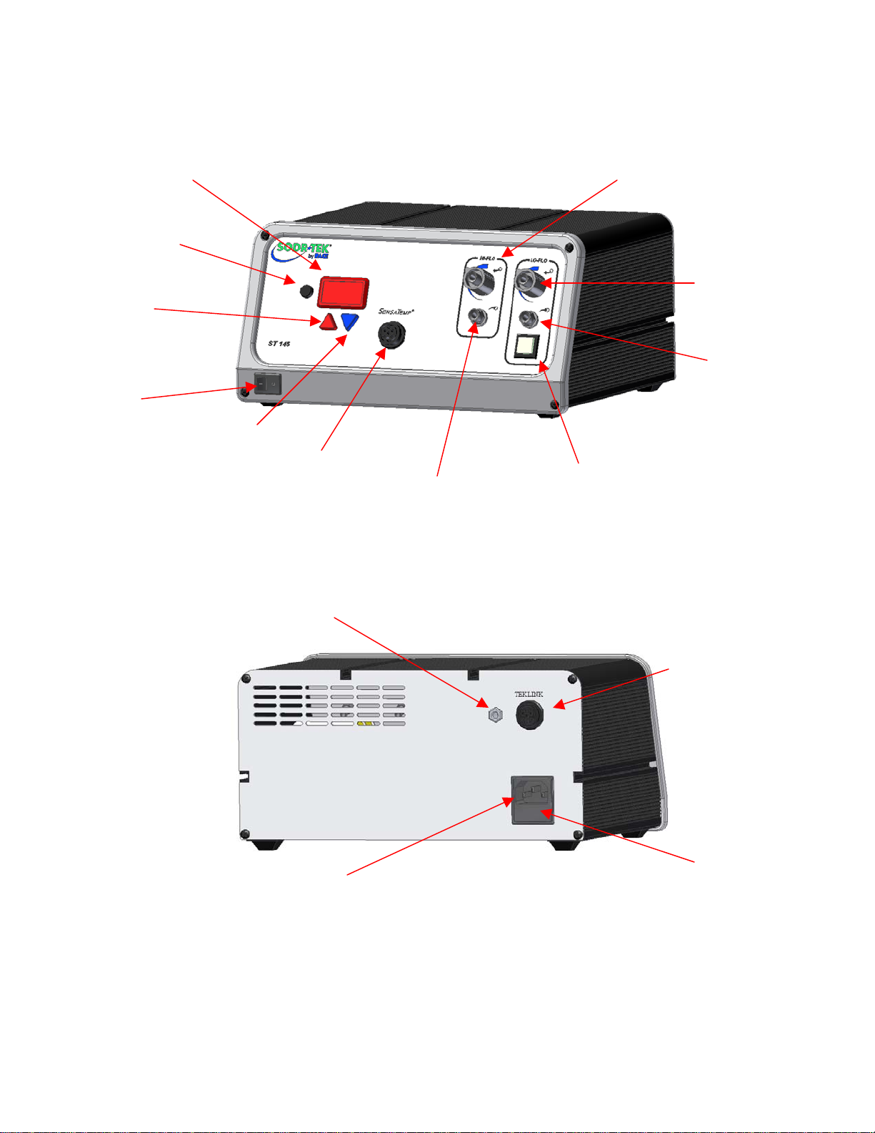
Parts Identification
Switc
p
p
g
p
p
ram Key
Pro
Key
Scroll U
Power Switch
AC Power Receptacle/Fuse Holder
LED Display
Scroll Down Key
Earth Ground Rece
Power Rece
tacle
tacle
HiFlo Vacuum Port
HiFlo Pressure Port
LoFlo Pressure Port
LoFlo Vacuum Port
Illuminated LoFlo Pump
h
TEKLINK Rece
Fuse
tacle
©2004 PACE Inc., Annapolis Junction, Maryland Page 4 of 22
All Rights Reserved
Page 5

Safety
Safety Guidelines
The following are safety precautions that personnel must understand and follow when using or
servicing this product.
1. POTENTIAL SHOCK HAZARD - Repair procedures on PACE products should be performed
by Qualified Service Personnel only. Line voltage parts may be exposed when the
equipment is disassembled. Service personnel must avoid contact with these parts when
troubleshooting the product.
2. To prevent personnel injury, adhere to safety guidelines in accordance with OSHA and other
applicable safety standards.
3. SensaTemp handpiece heaters and installed tips are hot when the handpiece is powered on
and for a period of time after power off. DO NOT touch either the heater or the tip. Severe
burns may result.
4. PACE Tip & Tool Stands and handpiece cubbies are designed specifically for use with the
associated handpiece and houses it in a manner that protects the user from accidental burns.
Always store the handpiece in its holder. Be sure to place the handpiece in its holder after
use and allow for cooling before storing.
5. Always use PACE systems in a well ventilated area. A fume extraction system such as those
available from PACE are highly recommended to help protect personnel from solder flux
fumes.
6. Exercise proper precautions when using chemicals (e.g., solder paste). Refer to the Material
Safety Data Sheet (MSDS) supplied with each chemical and adhere to all safety precautions
recommended by the manufacturer.
©2004 PACE Inc., Annapolis Junction, Maryland Page 5 of 22
All Rights Reserved
Page 6
System Set-Up
Set up the ST 145 system using the following steps and associated drawings.
1. Store the shipping container in a convenient location. Reuse of these
containers will prevent damage if you store or ship your system.
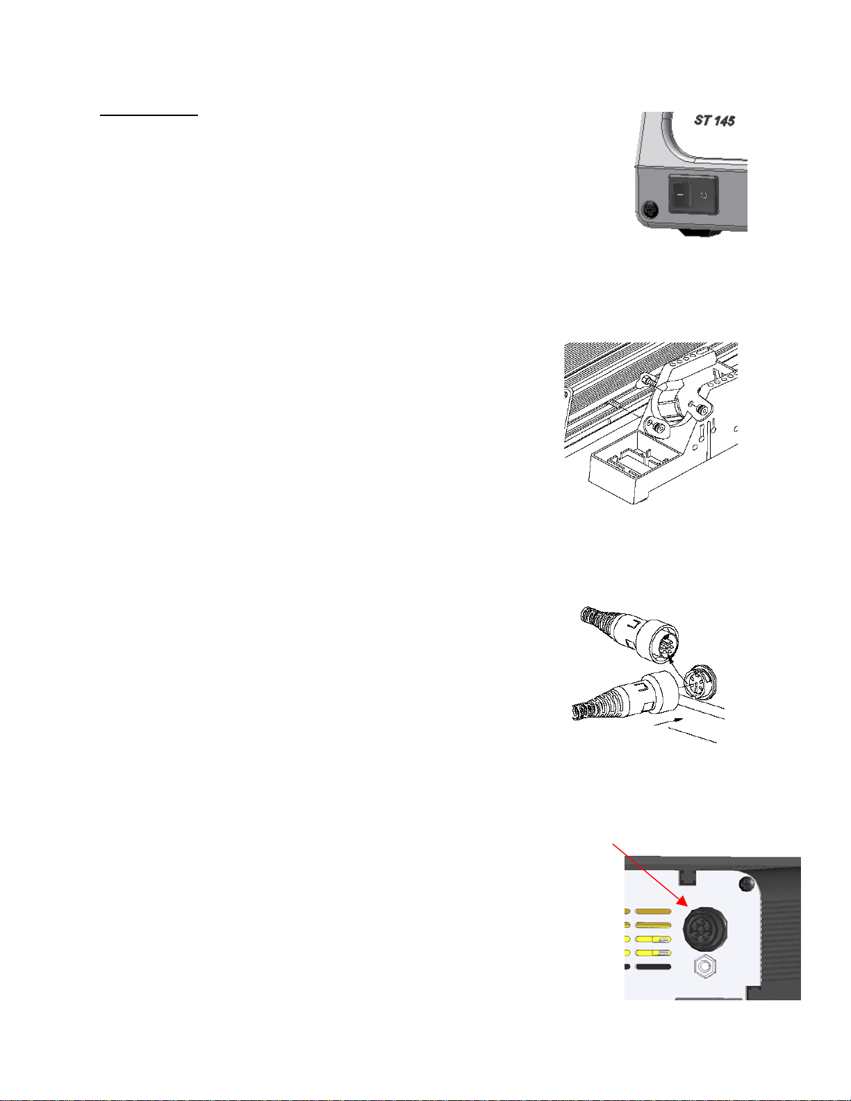
2. Place the Power Switch in the “OFF” or “0” position.
Tip & Tool Stand
The Tip & Tool Stand can be mounted to the power source. If the system will be placed on the
workbench, this is recommended. If the ST 145 is to be mounted under the workbench or shelf, the
Tip & Tool Stand should not be mounted to the power source.
1. To attach the stand to the power source:
a) Insert the 2 Mounting Screws (head first) into the
power source mounting slots (plastic case shown).
Slide the screws toward rear of the power source.
b) Place the Tip & Tool Stand beside the power source.
Insert ends of the 2 Mounting Screws into the 2 Tip &
Tool Stand mounting holes as shown.
c) Install a Thumb Nut onto the end of each Mounting
Screw and tighten Thumb Nuts.
2. Place the handpiece into its Tip & Tool Stand.
Handpiece Connection
Connect the handpiece connector plug into the Power Receptacle in
the following manner.
1. Align guide on connector with slot on power receptacle.
2. Insert connector into power receptacle.
3. Turn the connector housing clockwise to lock in place.
CAUTION: Ensure that only one air hose is connected to the
VACUUM or controllable PRESSURE port at one time. Attachment to both ports
simultaneously will cause deterioration in performance.
TEKLINK
TEKLINK Receptacle
The TEKLINK receptacle located on the back panel of the power supply allows
you to interface the VACUUM and PRESSURE features of your ST 125/145
with the SODRTEK ST 25/45 system. This feature gives you the freedom to
operate air-controlled handpieces (SX-70/80, TP-65, or TJ-70/80) from an ST
25/45 system through the VACUUM and PRESSURE ports of your ST
125/145. To link your ST 125/145 system to the ST 25/45 system, perform the
following procedure.
©2004 PACE Inc., Annapolis Junction, Maryland Page 6 of 22
All Rights Reserved
Page 7

1. Place the ST 25/45 system adjacent to (side by side) or stacked on top of your ST 125/145
system.
2. Use the TEKLINK cable (sold separately) to connect the systems together. The TEKLINK
Receptacle is located on the back panel of each power supply.
3. Ensure the VisiFilter assembly is connected to either the ST 125/145 VACUUM Port.
4. Connect the air hose of the handpiece being used, to either the VisiFilter assembly or the
controllable PRESSURE port.
The TEKLINK Remote Box (sold separately) allows the connection of up to three ST 25/45 systems in
any combination.
NOTE: Systems connected together through the TEKLINK system must be used and controlled by a
single operator. Any attempt to operate by more than one individual can create a hazardous
condition and will cause deterioration in performance.
System Power Up
1. Insert the female end of the power cord into the AC Power Receptacle on the rear panel of
the power source.
2. Plug the prong end (male end) of the power cord into an appropriate 3 wire grounded AC
supply receptacle.
CAUTION: To insure operator and ESD/EOS safety, the AC power supply receptacle must be
checked for proper grounding before initial operation.
Set-Up Mode
PACE recommends that you not read the “Set-Up Mode” section until after you feel comfortable with
system operation. Please read the following “Operation" section thoroughly before changing the system
settings.
Introduction
The menu driven LED Display of the ST 145 system in the Set-Up Mode allows you to easily
customize your system. No calibration adjustments are necessary to maintain the accuracy of the
system. In Set-Up Mode, you can:
1. Enter, remove or change a Password.
2. Set the Default Temperature scale to °F or °C as desired.
3. Change the Upper and Lower Temperature limits.
4. Enter a Temperature Offset Constant (Auto Tip Temperature Compensation).
5. Enable or disable the Temperature Setback feature and adjust the timeout period (if
enabled).
6. Enable or disable the Auto Off feature and adjust the time-out period (if enabled).
©2004 PACE Inc., Annapolis Junction, Maryland Page 7 of 22
All Rights Reserved
Page 8

7. Enable or disable the Average Temperature feature. The following instructions should be
performed to familiarize the operator with the system.
Entering Set-Up Mode
1. Place Power Switch in the “OFF” (“0”) position.
2. Press and hold the Program (
3. Place Power Switch in the "ON" (“I”) position. Release the Program ( ) Key.
Password
4. The LED Display will display the version of the microprocessor and
change to read “P--” or "EP0".
5. If the display reads "EP0", a Password has been stored in system
memory. Enter the 5 key sequence Password. If the Password entered
is incorrect, "no" appears on the display and the system then returns to
normal operation. If this occurs, repeat steps 1 through 5 and enter
the correct Password.
6. The LED Display reads "P- -". Choose one of the following options:
a) Press the Program (
Password).
b) Press and release the Scroll Up
c) Press and release the Scroll Down
do not wish to store a Password.
7. If the LED Display now reads "EP0", select and enter a 5 key password sequence. Make a
note of the entered Password. As the Password is entered, the last digit of the display will
count up with each key entry. After the fifth key entry, proceed to step 8.
Temperature Scale
8. The LED Display now shows the stored default Temperature Scale (°C
or °F temperature shown on LED Display). Choose one of the following:
a) Press the Program (
Temperature Scale.
b) Press and release the Scroll Up
and release the Program (
Temperature Limits
9. The LED Display now shows the stored default High ("Hi") Temperature
Limit with the display alternating to show "Hi" and the stored limit.
Choose one of the following:
a) Press and release the Program (
Temperature Limit.
b) Press and release the Scroll Up (s) Key to increase the stored High
) Key.
) Key to keep the currently stored Password (including no
Key to enter a new Password.
Key if you wish to remove a stored password or
) Key to keep the stored default
Key to change the default Temperature Scale. Press
) Key.
) Key to keep the stored High
©2004 PACE Inc., Annapolis Junction, Maryland Page 8 of 22
All Rights Reserved
Page 9

Temperature Limit (up to 482°C, 900°F). Press and release the Program Key to proceed
to the next step.
c) Press and release the Scroll Down
Limit. Press and release the Program (
10. The LED Display now shows the stored default Low ("Lo") Temperature
Limit with the display alternating to show "Lo" and the stored limit.
Choose one of the following:
a) Press and release the Program (
Temperature Limit (204°C, 400°F min.).
b) Press and release the Scroll Up
Press and release the Program (
c) Press and release the Scroll Down
Limit. Press and release the Program (
Offset Constant
11. The LED Display now shows the stored Offset Constant with the display alternating to show
"OF" and the stored Offset Constant. Choose one of the following:
a) Press and release the Program (
stored Offset Constant.
b) Press and release the Scroll Up
Offset Constant of 0-133°C (0-240°F) can be stored. Press and release the Program (
c) Press and release the Scroll Down
Press and release the Program ( ) Key to proceed to the next step.
NOTE: If the attached handpiece is disconnected when the system is powered up, any
Temperature Setback
12. The LED Display now shows the stored Temperature Setback time as
"S-X" (x=0 thru9). Time is shown as tens of minutes (e.g., "S3" equals 30 minutes). A display of "S- 0" indicates that Setback is
disabled. Choose one of the following:
a) Press and release the Program (
Setback time.
b) Press and release the Scroll Up
Temperature Setback time. Press and release the Program (
next step.
c) Press and release the Scroll Down
Temperature Setback time. Press and release the Program (
next step.
Key to decrease the stored High Temperature
) Key to proceed to the next step.
) Key to keep the stored Low
Key to increase the stored Low Temperature Limit.
) Key to proceed to the next step.
Key to decrease the stored Low Temperature
) Key to proceed to the next step.
) Key to keep the currently
Key to increase the stored Offset Constant. An
) Key to proceed to the next step.
Key to decrease the stored Offset Constant.
stored Offset Constant is reset to zero. The Offset Constant must be entered again
in the Set-Up Mode.
) Key to keep the currently stored Temperature
Key to enable and/or increase the stored
) Key to proceed to the
Key to decrease or disable the stored
) Key to proceed to the
©2004 PACE Inc., Annapolis Junction, Maryland Page 9 of 22
All Rights Reserved
Page 10

Auto Off
13. The LED Display now shows the stored Auto Off time as "AOx" (x=0 thru
9). Time is shown as tens of minutes (e.g., "AO3" equals 30 minutes). A
display of "AOO" indicates that Auto Off is disabled. Choose one of the
following:
a) Press and release the Program (
b) Press and release the Scroll Up
and release the Program (
c) Press and release the Scroll Down
time. Press and release the Program (
Temperature Display Impedance
14. The LED Display now shows the Temperature Display Impedance mode as
Enabled or Disabled ("AC0" = Disabled and "AC1" = Enabled). Choose
one of the following:
a) Press and release the Program (
or Enabled).
b) Press and release the Scroll Up Key to change the stored setting (Disabled or Enabled).
Press and release the Program (
Exiting Set-Up Mode
15. The LED Display now reads "End". The Set-Up Mode procedure is now
complete. Choose one of the following steps:
a) Press and release the Scroll Up
return to normal operation.
b) Press and release the Scroll Down
Set-Up Mode procedure.
Heater Burn In Procedure
Use the following instructions to perform the Heater Burn In procedure.
NOTE: Ensure that the system is placed in a well-ventilated area. Smoke will be generated during
the burn in cycle and while soldering. Fume extraction equipment is recommended.
1. Place the Power Switch in the “OFF” (0) position.
2. Ensure that the handpiece is connected to the power source. If a plastic cap is present on
the heater assembly, remove it and discard. The cap is used for shipping purposes only.
3. Press and hold the Program (
4. Place Power Switch in “ON” (I) position.
) and Scroll Up keys together.
) Key to keep the currently stored Auto Off time.
Key to enable and/or increase the Auto Off. Press
) Key to proceed to the next step.
Key to decrease or disable the stored Auto Off
) Key to proceed to the next step.
) Key to keep the currently stored setting (Disabled
) Key to proceed to the next step.
Key to exit Set-Up Mode and
Key to return to the start of the
©2004 PACE Inc., Annapolis Junction, Maryland Page 10 of 22
All Rights Reserved
Page 11

5. The display will read “brn” when the Program ( ) and Scroll Up keys are
released.
6. Press the Scroll Up
begin to heat. The temperature of the heater will stabilize at 315°C (600 °F) for 10
minutes.
7. At the conclusion of the 10-minute period, the heater temperature will increase to
427°C (800°F) for 15 minutes.
8. At the conclusion of the 15-minute time period, the heater is turned off and the Display will
read “End”. Press and release the Scroll Up Key to exit Heater Burn In and return the to
normal operation.
CAUTION: The heater will be hot at the conclusion of the Burn In procedure.
NOTE: The microprocessor circuitry within the unit monitors the system to ensure proper results.
If any abnormalities are encountered, the Burn In cycle will be interrupted and an error
message displayed. If this situation should occur, turn the system off and perform the
procedure again. If the cycle is interrupted a second time, refer to the Corrective
Maintenance section and check for handpiece malfunction information. If a second
handpiece is available, perform the procedure using that handpiece.
This procedure should be performed whenever a new handpiece or new heater is
connected to the system. Ensure that the system is placed in a well-ventilated area.
Smoke will be generated during the burn in cycle and while soldering. Fume extraction
equipment is recommended.
Quick Start Procedure
Key to initiate the Burn In Mode. The handpiece heater will
The ST 145 system is very easy to operate. As received from the factory, the system can be quickly set
up for use in standard desoldering/soldering operations. Simply perform the following Quick Start
Procedure to begin system operation.
1. Ensure that the Set-Up procedure has been performed; including the Heater Burn In procedure.
Check for the following:
a) Handpiece connections (connector plug and air hose) to the power
source.
b) Proper tip installed in handpiece.
c) Power cord connection between house AC supply receptacl e and
the power source.
d) House air supply connection to power supply.
2. Turn the Power Switch “On” (“I”).
3. Press the Scroll Up
within 5 seconds, the system will revert to normal operation. Allow time for the system to change
back.
4. Press the Scroll Up
5. Adjust the Set Temperature in the following manner:
Key. The Set Temperature is now displayed. If no other Key is pressed
Key. The Set Temperature is now displayed; immediately perform step 5.
©2004 PACE Inc., Annapolis Junction, Maryland Page 11 of 22
All Rights Reserved
Page 12

a) Press and release the Scroll Up Key to increase Tip Temperature in increments. Press
and release the Scroll Down
Key to decrease Tip Temperature. Observe the display as
the Set Temperature increases in increments of 1°.
NOTE: If a Password has been previously programmed into the system, "EP0" will appear
on the LED Display at this point. When this message appears, the operator must
enter the correct 5 key Password before adjusting the temperature. Refer to
“Password” in the “Operation” portion of this manual.
b) Adjust the temperature by pressing and holding Scroll Up
Key. Observe the display as
the Set Temperature increases first in increments of 1° and then in increments of 10°.
Release the key.
c) Using the Scroll Keys, adjust the temperature to any standard operating temperature used by
your company.
NOTE: The Set Temperature can only be within the set temperature limits. If a limit (upper
or lower) is reached, the lower limit would display “OFF”; the upper limit would not
allow the Set Temperature to exceed that limit. Temperature limits can be adjusted
in the Set-Up Mode.
6. Press the Program Key (
). The system will now return to normal operation.
7. Observe the Digital Readout as the temperature stabilizes at the desired Set Tip Temperature.
8. Manually force the system into Temperature Setback in the following manner:
a) Press and hold the Scroll Down
Key and the Scroll Up Key.
b) Release both keys.
9. The system is now in Temperature Setback. Observe the flashing of the LED Display and the
decreasing of the tip temperature. Allow time for the temperature to stabilize at 177°C (350°F).
NOTE: If Auto Off has been enabled (turned on in Set-Up Mode), the system will enter Auto
Off (temperature Off and LED Display flashing "Off") after the preset time of handpiece
inactivity. Auto Off can be exited by pressing any key.
10. Manually force the system out of Temperature Setback in either of the following manners:
a) Press and release a Key (either of the 3 keys). This is the preferred method.
b) Wipe the hot handpiece tip on a wet sponge to lower the tip temperature.
c) Turn the Power Switch Off ("0") and then back on ("I").
11. The system is now in normal operation. Observe the LED Display as the tip temperature
increases to the Set Temperature. Allow time for the temperature to stabilize at the Set
Temperature.
NOTE: Read the “Operation” and “Set-Up Mode” sections of this manual to utilize the full
capabilities of the system. This is especially important when using large solderin g
tips or other SensaTemp handpieces.
©2004 PACE Inc., Annapolis Junction, Maryland Page 12 of 22
All Rights Reserved
Page 13

12. If you have a Sodr-X-Tractor or other PACE air handpiece connected to your system, press and
hold the handpiece Vacuum Switch. You will hear a noise as the motor pump starts up and
continues to run. Release the Vacuum Switch.
Operation
Auto Tip Temperature Compensation and Offset
Differences between the temperature settings and true tip temperatures are negligible when using
Thru-Hole, single point desoldering tips. With any heating system however, True Tip Temperatures
can differ greatly from temperature settings when using larger SMT soldering tips. This difference is
called Tip Temperature Offset. The ST 145 Auto Tip Temperature Compensation feature lets you set
and display true tip temperatures regardless of size and type of tip or handpiece. PACE recommends
the use of the Tip & Temperature Selection System booklet (PACE P/N 5050-0251) as a guide to
accurately set and maintain a true tip temperature for any size and type of SMT tip. The booklet
contains a listing of PACE tip information including the Tip Offset Constant (for each tip), which must
be stored in system memory to ensure tip temperature accuracy. Refer to the “Set-Up Mode” section
of this manual for instructions on using this feature.
As with any system, Set and Operating Tip Temperatures are only exactly equal when the handpiece
is idling (unloaded at equilibrium). During use, (i.e., under load) the Operating Tip Temperature will
usually be lower.
Password
The Password feature of the ST 145 system, when activated, will prevent unauthorized alteration of
stored system temperature parameters and feature settings (refer to the “Factory Settings”). If a
Password has been installed, the LED Display will display an instruction to enter the Password (a 5
key sequence of the keys on the system front panel) when a setting change is attempted. Entry of
the correct Password at this point will allow the operator to proceed with the desired changes. Once
the correct Password has been entered, the operator can continue to make changes to Tip
Temperature settings. To reactivate the Password protection, simply turn the system Power Switch
off and then back on. The system is now in normal operation. Refer to the “Set-Up Mode” section of
this manual for instructions on entering, changing or removing a Password.
LED Display, Normal Operation
The LED Display provides a 3 digit display of temperature information.
The LED Display will show:
1. A display of "888" on power up to ensure that all LEDs on the
display are working.
2. A display of the software version of the installed microprocessor
(e.g., "1-1") for 2 seconds on initial power up after the "888" is displayed.
3. Actual tip temperature of the connected handpiece during normal operation.
4. The tip temperature displayed will flash when the system is in Temperature Setback.
©2004 PACE Inc., Annapolis Junction, Maryland Page 13 of 22
All Rights Reserved
Page 14

5. The displayed temperature will decrease and stabilize at 177°C (350°F) when
the system is in Temperature Setback.
6. "OFF" when the Set Tip Temperature has been set to Off (below minimum
set tip temperature). Refer to the "Set-Up Mode" portion of this manual.
7. "OFF" plus the LED Display will be flashing when the unit has entered Auto
Off. Refer to the "Set-Up Mode" portion of this manual.
8. Error messages ("OSE", "SSE" or "OCE") if a system fault is detected. Refer
to the "Corrective Maintenance" portion of this manual.
LED Display, Temperature Adjust Mode
The LED Display will show the following when adjusting the desired Set Tip Temperature.
1. The Set Tip Temperature.
2. "HiL" (High Temperature Limit) when adjusting the set tip temperature and
the maximum allowable temperature is exceeded. Refer to the "Set-Up
Mode" portion of this manual.
3. "OFF" (Low Temperature Limit) when adjusting the set tip temperature and
the minimum allowable temperature is exceeded. Refer to the "Set-Up Mode"
portion of this manual.
4. "EP0" will be displayed if a Set Tip Temperature adjustment is attempted and
a Password has been stored in system memory. As the 5 key Password is
entered, the zero will increase by one as each key entry is made. Upon entry
of the fifth password key, the display will change to the Set Tip Temperature
if the entered Password matches the stored Password.
5. "no" will be displayed if the entered password does not match the stored
Password.
Vacuum Pump Operation
The PACE ST 145 contains two different vacuum pumps.
1. HiFlo Pump
a) To activate, depress the handpiece activation button.
b) Optional Foot Pedal can be used to actuate the HiFlo pump via the rear TEKLINK
socket.
2. LoFlo Pump
a) This pump is activated by the front Illuminated LoFlo Pump Switch.
b) For use with the TJ-80 and PV-65 Pik Vac Wand.
Handpiece Vacuum/Pressure
To set up your Sodr-X-Tractor air hose connection, perform the following steps:
©2004 PACE Inc., Annapolis Junction, Maryland Page 14 of 22
All Rights Reserved
Page 15

1. Air Hose To Handpiece Connection
a) Attach one end of a 137cm (54 inch) length of air hose to the metal tube in the back
of the handpiece.
b) If you have a PACE system incorporating only one
handpiece, attach the air hose to the power cable using the
supplied Hose Clamps. Space them evenly along the length
of the power cable starting at a point 6 inches from the ends
of the handpiece.
c) If you have a PACE system incorporating 2 or more air
handpieces, you may wish to leave the air hose assembly
unattached to allow a quick change to any air handpiece
being used.
2. Prepare a VisiFilter in the following manner:
a) Connect a 1 inch (2.5cm) length of clear pvc air hose to the
FLOW OUT side of the VisiFilter; push and turn the hose
onto the VisiFilter nipple to seat.
b) Insert the ribbed end of a male quick connect hose mount fitting (P/N 1259-0087) into the
free end of the 1 inch (2.5cm) length of air hose connected to the FLOW OUT side of the
VisiFilter.
c) Connect the free end of the 137cm (54 inch) length of air hose to the FLOW IN side of
the VisiFilter.
d) Insert the end of the quick connect hose mount fitting (on VisiFilter FLOW OUT side) into
the power source Vacuum Port.
3. When using air pressure, and/or utilizing multiple air handpieces, PACE recommends the use of
the following set up procedure
assortment of quick connect air fittings are supplied with each additional air handpiece.
a) Disconnect the 137cm (54 inch) length of air hose from the FLOW IN side of the VisiFilter
assembly. Insert the ribbed end of a male quick connect hose mount fitting (P/N 1259-0087)
into the free end of this air hose.
b) Connect the free end of a 1 inch (2.5cm) length of air hose with an installed female quick
connect hose mount fitting (P/N 1259-0086) to the FLOW IN side of the VisiFilter Assembly.
c) The 137cm (54 inch) length of air hose can now be easily moved between the VisiFilter
Assembly and the Controllable Pressure Port. The VisiFilter assembly remains connected to
the Vacuum Port.
4. Additional fittings may also be added to the hose connection at the rear of each air handpiece
to ease changing of handpieces.
NOTE: When removing any air hose, turn and pull. Do not attempt to pull hose directly off.
Damage to or breakage of fitting or VisiFilter may occur. Use your Sodr-X-Tractor with
a clean VisiFilter element. Otherwise a deterioration in performance or damage to the
unit may occur.
which utilizes additional quick connect hose mount fittings. An
©2004 PACE Inc., Annapolis Junction, Maryland Page 15 of 22
All Rights Reserved
Page 16

Temperature Setback Mode
To preserve tip life and save energy, the ST 145 system can be programmed to automatically set
back its Tip Temperature to 177°C (350°F) after a selected period of handpiece inactivity (adjustable
10-90 minutes in Set-Up Mode). As received from the factory, this feature is enabled. Refer to the
“Set-Up Mode” section of this manual to disable or adjust the time-out period of this feature. The
operator can also force the system into Temperature Setback.
Activation
There are two ways in which the system will activate the Temperature Setback feature.
1. AUTOMATIC ACTIVATION – The system memory can be programmed so that the
system will automatically activate Temperature Setback after a selected period (1090 minutes) of handpiece inactivity. See the “Set-Up Mode” section for details on
programming this feature.
2. MANUAL ACTIVATION – The operator can manually force the system to place the
system in Temperature Setback by performing the following procedure.
a) Press and hold the Scroll Down
b) Press the Scroll Up
Key.
c) Release both keys.
Operation
Temperature Setback is indicated by the following.
1. The LED Display will be flashing
2. The Operating Temperature will stabilize at 177°C (350°F).
Exiting Temperature Setback
Listed below are 3 different ways to exit Temperature Setback.
1. Press and release either Scroll Key
2. Wipe the hot handpiece tip on a wet sponge to lower the tip temperature.
3. Method “1” is preferred but you can turn the Power Switch “OFF” (“0”) and then back
“ON” (“I”).
Set Tip Temperature and Tip Offset Constant values will be simultaneously restored. Observe
the LED Display as the Operating Tip Temperature stabilizes at the Set Tip Temperature. For
optimum performance, do not attempt to use the attached handpiece until the Set Tip
Temperature is achieved.
Key.
or . This is the preferred method.
©2004 PACE Inc., Annapolis Junction, Maryland Page 16 of 22
All Rights Reserved
Page 17

Auto Off Safety System Mode
When enabled, the Auto Off safety system of the ST 145 system removes power 10-90 minutes
(enabled/disabled and adjustable in Set-Up Mode) after entering Temperature Setback.
When the system has entered Temperature SetBack, an Auto Off timer within the system circuitry
will start running (if Auto Off is turned on in Set-Up Mode):
1. If any key is pressed during the selected time out period, the Auto Off timer is reset. The
system will return to normal operation.
2. At the end of the time out period, the system will enter Auto Off. Power is removed, the
LED Display will show “OFF ” and the display will be flashing.
Exiting Auto Off
Auto Off can be exited; returning to normal operation by:
1. Pressing and releasing a Key (either of the 3 keys).
OR
2. By turning the Power Switch OFF (“0”) and then back ON (“I”).
LED Display Accuracy
No adjustments are necessary to maintain the accuracy of the system.
LED Display Message Codes
Following LED Display message codes which may appear if a mistake is made by the
operator (e.g., wrong Password entry) or if the system has malfunctioned.
LED Display Message Description
The incorrect Password has been entered. The
displayed message will time out after 6 seconds
and revert back to normal operation. Enter the
Password.
The LED Display is flashing.
The LED Display is flashing.
The LED Display is flashing.
No handpiece is connected to the Power
Receptacle. Connect the handpiece.
The handpiece heater assembly sensor is open.
Refer to the respective handpiece manual.
The handpiece heater assembly is shorted. Refer
to the respective handpiece manual.
The handpiece heater assembly may be defective.
Refer to the respective handpiece manual.
Power source malfunction. Contact the PACE
Service Department for assistance.
©2004 PACE Inc., Annapolis Junction, Maryland Page 17 of 22
All Rights Reserved
Page 18

Corrective Maintenance
Power Source
Refer to the table below. Most malfunctions are simple and easy to correct.
Symptom Probable Cause Solution
No power to system. Blown Fuse Check handpiece using "Heater Assembly
Checkout Procedures" in the respective
handpiece manual. Replace the fuse (located
in the AC Receptacle Fuse Holder) with one
of the same rated value.
Power Source Malfunction Contact the PACE Service Department for
assistance.
Insufficient vacuum or
air pressure. Motor
Pump runs.
No vacuum or air
pressure. Motor Pump
does not run.
Handpiece air hose has a kink
or a hole in the hose.
VisiFilter or handpiece filter
Check handpiece hose. Replace air hose if
necessary
Replace VisiFilter or handpiece filter.
clogged.
Handpiece chamber not
seated properly in handpiece.
Defective Motor Pump
Assembly.
Check handpiece. Reseat chamber if
necessary.
Check vacuum and air pressure at Motor
Pump Assembly air hose connections.
Replace Motor Pump Assembly if necessary.
Defective handpiece. Check handpiece using "Heater Assembly
Checkout Procedures", in the respective
handpiece manual.
Defective Motor Pump
Assembly.
Check for 12 VDC at motor terminals with
handpiece switch actuated. Replace Motor
Pump Assembly if defective.
Defective Main PCB Assembly If there is no 12 VDC at Motor Pump
Assembly, repair or replace Main PCB
Assembly.
Handpiece will not
heat
Defective Handpiece Heater Check handpiece using "Heater Assembly
Checkout Procedures" in the respective
handpiece manual.
Power Source Malfunction Contact the PACE Service Department for
assistance.
Handpieces
Please refer to the specific handpiece manual for the “Heater Assembly Checkout Procedures.”
©2004 PACE Inc., Annapolis Junction, Maryland Page 18 of 22
All Rights Reserved
Page 19

Factory Settings
The ST 145 system comes equipped with a number of features which may be
adjusted, enabled or disabled as desired by the user. Listed below are the featu r es
and factory settings of each. To change and/or learn about any of these features,
refer to the applicable part of the “Set-Up Mode” portion of this manual.
FEATURE FACTORY SETTING
Password None Entered
Default Temperature Scale (°C/°F)
"Hi L" (upper) Temperature Limit 482°C (900°F)
"LO" (lower) Temperature Limit 204°C (400°F)
Set Temperature "OFF"
Tip Offset Constant "0"
Temperature Setback Enabled
Setback Time 30 Minutes
Auto Off Enabled
Time To Auto Off 30 Minutes
Definitions
Please read and become familiar with the definitions of each of the following terms which are used
repeatedly in the following operational procedures.
AUTO OFF - Safety feature which turns power off (10-90 minutes, settable in 10 minute increments)
after the system has entered Temperature Setback.
NORMAL OPERATION - Normal operating mode of the system in which the Operating Tip
Temperature is displayed.
OPERATING TIP TEMPERATURE - The true tip temperature at which the handpiece tip operates at
any given time.
SET TIP TEMPERATURE - The operator selected idle tip temperature entered into the system
memory.
SET-UP MODE - Mode of operation in which the operator can quickly and easily adjust the system
parameters (e.g., temperature limits, password, setback time).
TEMPERATURE ADJUST MODE - Mode of operation in which the operator can quickly and easily
adjust the Set Tip Temperature.
TEMPERATURE DISPLAY IMPEDANCE (TDI) MODE - Stabilizes the tip temperature shown on the
LED Display by ignoring minor temperature fluctuations. Displayed changes in temperature are
delayed (impeded) for two seconds when a load is applied to the tip. Two seconds after the load is
removed, the displayed temperature will begin rising to set temperature. Particularly useful in a
°F for 115V Systems
°C for 230V Systems
©2004 PACE Inc., Annapolis Junction, Maryland Page 19 of 22
All Rights Reserved
Page 20

production environment for monitoring of set temperatures, since under most production
circumstances the temperature will not deviate.
TEMPERATURE SETBACK - System feature which, when enabled, will independently set back the
Set Tip Temperature to 177°C (350°F) after a user selected period of handpiece inactivity (10 to 90
minutes, settable in 10 minute increments). This feature is enabled (or disabled) in the Set-Up Mode.
TIP OFFSET CONSTANT - Specific value for a given handpiece/tip combination upon which the
system automatically calculates the correct Tip Temperature Offset at any entered Set Tip
Temperature. This value is the temperature loss (Tip Temperature Offset) at 371°C (700°F) and is set
in the Set-Up Mode. A value of 0-115°C (0-240°F) may be entered in the Set-Up Mode.
TIP TEMPERATURE OFFSET - Difference in value between the temperature measured by the
temperature sensor (at the heater) and the true temperature of the tip at a given Set Tip Temperature.
Packing List
Item # Description Part Number ST 145
1 System Power Supply 1 0
2 System Power Supply (Export) 0 1
5 Power Cord, 115V 1332-0094 1 0
6 Power Cord, 230V 1332-0093 0 1
7 Tip Tool 1100-0206 0 0
8 Hex Key, .050 1100-0237 1 1
9 Hot Grip Removal Pad 1100-0307 0 0
10 Operations Manual CD CD5050-0459 1 1
Only
Spare Parts
Item # Description PACE Part Number
Fuse, 1.25 Amp, 250 V, Time Lag (ST 145) 1159-0251-P5 1
Fuse, 0.63 Amp, 250 V, Time Lag (ST 145E) 1159-0252-P5
2 TEKLINK Cable 1332-0252-P1
3 TEKLINK Remote Box 3008-0218-P1
4 Tip & Temperature Selection Chart 5050-0251
Service
Please contact PACE or your local distributor for service and repair.
ST 145 E
Only
©2004 PACE Inc., Annapolis Junction, Maryland Page 20 of 22
All Rights Reserved
Page 21

“SODRTEK by PACE” LIMITED WARRANTY STATEMENT
Limited Warranty
Seller warrants to the first user that products manufactured by it and supplied hereunder are free of
defects in materials and workmanship for a period of one (1) year from the date of receipt by such user.
Monitors, computers and other brand equipment supplied but not manufactured by PACE are covered
under their respective manufacturer’s warranty in lieu of this Warranty.
This warranty does not cover wear and tear under normal use, repair or replacement required as a result
of misuse, improper application, mishandling or improper storage. Consumable items such as tips,
heaters, filters, etc. which wear out under normal use are excluded. Failure to perform recommended
routine maintenance, alterations or repairs made other than in accordance with Seller’s directions, or
removal or alteration of identification markings in any way will void this warranty. This warranty is
available only to the first user, but the exclusions and limitations herein apply to all persons and entities.
SELLER MAKES NO OTHER WARRANTY, EXPRESS OR IMPLIED, AND MAKES NO WARRANTY OF
MERCHANTABILITY OR FITNESS FOR A PARTICULAR PURPOSE.
Seller will, at its option, repair or replace any defective products at its facility or other location approved by
it at no charge to user, or provide parts without charge for installation by the user in the field at user’s
expense and risk. User will be responsible for all costs of shipping equipment to Seller or other location
for warranty service.
EXCEPT FOR THE REMEDY ABOVE DESCRIBED, UNLESS OTHERWISE REQUIRED BY
APPLICABLE LAW, SELLER WILL HAVE NO OTHER OBLIGATION WITH REGARD TO ANY BREACH
OF WARRANTY OR OTHER CLAIM WITH RESPECT TO THE PRODUCTS, OR LIABILITY FOR ANY
DIRECT, INDIRECT, CONSEQUENTIAL, OR INCIDENTAL LOSS OR DAMAGE CAUSED BY OR
OCCURRING IN CONNECTION WITH ANY OF THE PRODUCTS.
Warranty service may be obtained by contacting the appropriate PACE Company or local Authorized
PACE distributor as set forth below to determine if return of any item is required, or if repairs can be made
by the user in the field. Any warranty or other claim with respect to the products must be made with
sufficient evidence of purchase and date of receipt, otherwise user’s rights under this warranty shall be
deemed waived.
For PACE USA Customers:
PACE, INCORPORATED
9030 Junction Drive
Annapolis Junction, Maryland 20701
Tel. 301-317-3588
FAX: 301-498-3252
For PACE EUROPE Customers:
PACE EUROPE LIMITED
Sherbourne House, Sherbourne Drive,
Tilbrook, Milton Keynes
MK7 8HX
United Kingdom
Tel. (44) 1908 277666
WARRANTY SERVICE FAX: (44) 1908 277 777
All other Customers:
Local Authorized PACE Distributor
©2004 PACE Inc., Annapolis Junction, Maryland Page 21 of 22
All Rights Reserved
Page 22

PACE Incorporated retains the right to make changes to specifications contained herein at any time,
without notice. Contact your local authorized PACE Distributor or PACE Incorporated to obtain the latest
specifications.
The following are trademarks and/or service marks of PACE, Incorporated, MD, USA:
INSTACAL
POWERPORT
™
, FUMEFLO™, HEATWISE™, PACEWORLDWIDE™, PERMAGROUND™,
™
, POWERMODULE™, TEMPWISE™, TIP-BRITE™, AUTO-OFF™, and
TEKLINK™.
The following are registered trademarks and/or service marks of PACE Incorporated, Annapolis Junction
Maryland U.S.A.
ARM-EVAC
SODRTEK
VISIFILTER
®
, FLO-D-SODR®, MINIWAVE®, PACE®, SENSATEMP®, SNAP-VAC®,
®
, SODR-X-TRACTOR®, THERMOFLO®, THERMOJET®, THERMOTWEEZ®,
®
, THERMO-DRIVE®, and TOOLNET®.
PACE products meet or exceed all applicable military and civilian EOS/ESD, temperature stability and
other specifications including MIL STD 2000, ANSI/JSTD 001, IPC7711, and IPC A-610.
www.paceworldwide.com
PACE USA PACE Europe
9893 Brewers Court Sherbourne House
Laurel, MD 20723 Sherbourne Drive
USA Tilbrook, Milton Keynes
MK7 8HX
United Kingdom
Tel: (301) 490-9860 (44) 01908-277666
Fax: (301) 498-3252 (44) 01908-277777
©2004 PACE Inc., Annapolis Junction, Maryland Page 22 of 22
All Rights Reserved
 Loading...