

Page 1

Operation and Maintenance Manual for the
SODRTEK
ST 125 Soldering System
P/N 5050-0534
®
Page 2

TITLE PAGE
General Information .......................................................................................................3
Introduction...........................................................................................................3
Specifications .......................................................................................................3
Parts Identification................................................................................................4
Safety Guidelines...........................................................................................................5
System Set-Up...............................................................................................................6
Tip & Tool Stand......................................................................................................6
Handpiece Connection............................................................................................6
TEKLINK..................................................................................................................6
System Power Up ..........................................................................................................7
Burn In Procedure..........................................................................................................7
Operation........................................................................................................................7
Tip Offset.................................................................................................................7
Variable Temperature Control.................................................................................8
Temperature/Dial Lock ...........................................................................................8
LED Operation.........................................................................................................8
Temperature Dial Adjustment ........................................................................................8
Vacuum Pump Operation........................................................................................9
Handpiece Vacuum Pressure..................................................................................9
Corrective Maintenance................................................................................................10
Power Source......................................................................................................10
Handpieces..........................................................................................................10
Packing List...................................................................................................................11
Spare Parts...................................................................................................................11
Service ..........................................................................................................................11
“SODRTEK by PACE” LIMITED WARRANTY STATEMENT.......................................12
Contact Information.......................................................................................................13
©2004 PACE Inc., Annapolis Junction, Maryland Page 2 of 13
All Rights Reserved
Page 3

General Information
Introduction
Thank you for purchasing the PACE SODRTEK
®
model ST 125 Analog Desoldering System. This
manual will provide you with the information necessary to properly set up, operate and maintain the
ST 125.
The ST 125 system is available in either 115 VAC or 230 VAC versions, which incorporates a highly
responsive SensaTemp (closed loop) control system providing up to 80 Watts of total power to a
single output channel. The 230 VAC version system bears the CE Conformity Marking, which
assures the user that it conforms to EMC 89/336/EEC.
The 115 VAC version systems conform to FCC Emission Control Standard, Title 47, Subpart B, Class
A. This standard is designed to provide reasonable protection against harmful interference when the
equipment is operated in a commercial environment.
Specifications
System Power Source Power Requirements
ST 125 Operates on 97-127 VAC, 50/60Hz, 90 Watts maximum at 115 VAC,
60Hz
ST 125E Operates on 197-253 VAC 50/60Hz, 80 Watts maximum at 230 VAC,
50Hz
Temperature Specifications
Handpieces Tip Temperature Range: 204 to 455°C (400 to 850°F) nominal.
Temperature Stability: ±1.1°C (±2°F) at idle from set tip temp.
NOTE: Actual minimum and maximum Operating Tip Temperatures may vary depending on
Handpiece, Tip Selection and application.
Vacuum And Air
Measurements at front panel Vacuum and Controllable Pressure Ports.
Vacuum Rise Time: ------- 150 ms average.
Vacuum: ............................ 51 cm Hg. (20 in. Hg.) (nominal)
Pressure: .......................... 1.44 Bar (21 P.S.I.) (nominal at MAX setting)
Air Flow: ........................... 6 SLPM (0.22 SCFM) maximum
EOS/ESD Specifications
The specifications shown below apply except on "Soft Ground Systems" which have a 1meg ohm
current limiting resistance and a label placed on the power source f ront panel referring to EN
100015-1.
Tip-To-Ground Resistance: Less than 2 ohms.
AC Leakage: Less than 2 Millivolts RMS from 50Hz to 10MHz.
Transient Level: Less than 500mV peak, out to 100MHz.
©2004 PACE Inc., Annapolis Junction, Maryland Page 3 of 13
All Rights Reserved
Page 4
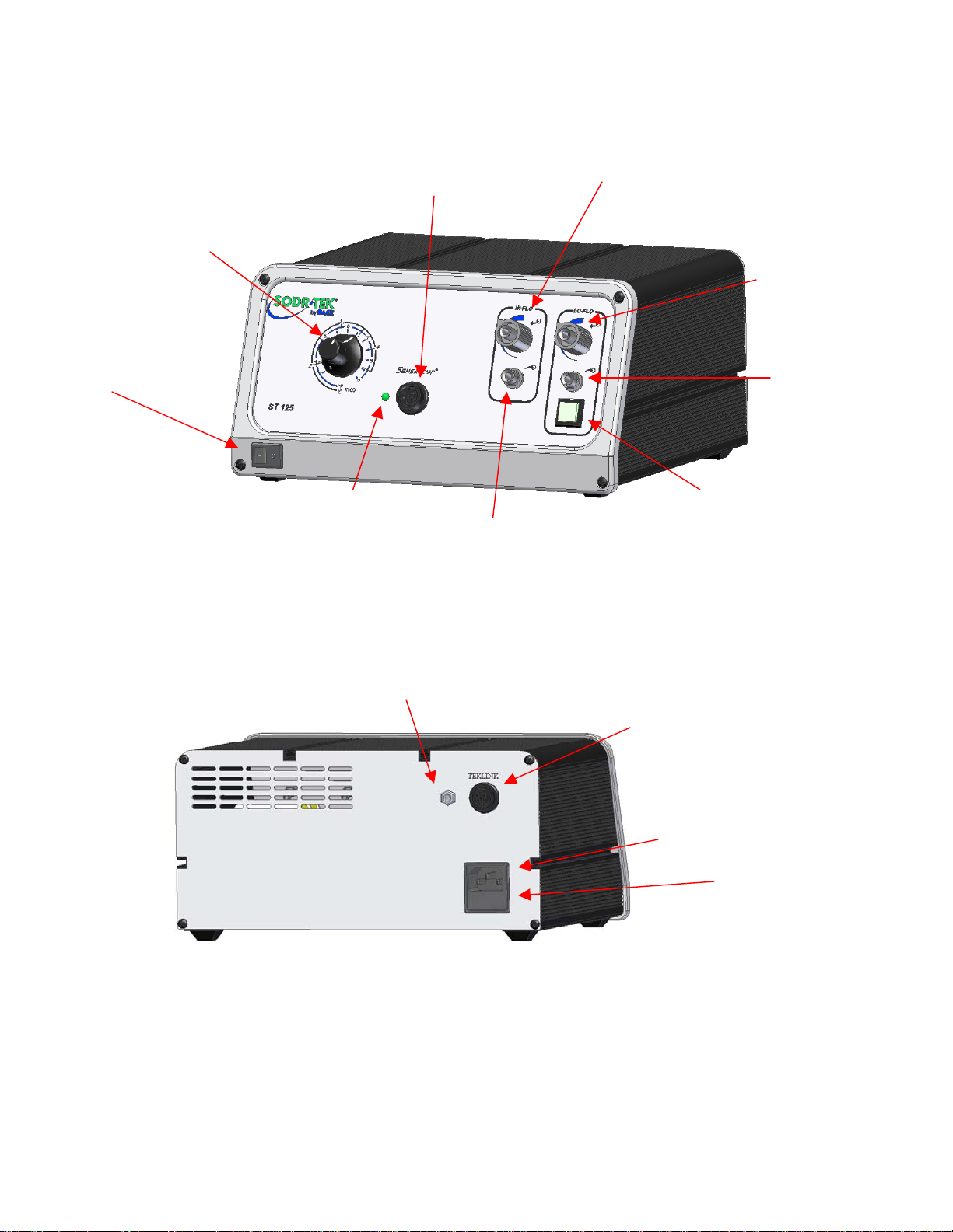
Parts Identification
Switc
p
p
Temperature Selection Dial
Power Switch
Power Receptacle HiFlo Pressure Port
Front Panel LED
Earth Ground Rece
HiFlo Vacuum Port
tacle
TEKLINK Rece
LoFlo Pressure Port
LoFlo Vacuum Port
Illuminated LoFlo Pump
h
tacle
AC Power Receptacle/Fuse Holder
Fuse
©2004 PACE Inc., Annapolis Junction, Maryland Page 4 of 13
All Rights Reserved
Page 5

Safety Guidelines
The following are safety precautions that personnel must understand and follow when using or servicing
this product.
1. POTENTIAL SHOCK HAZARD - Repair procedures on PACE products should be performed
by Qualified Service Personnel only. Line voltage parts may be exposed when the
equipment is disassembled. Service personnel must avoid contact with these parts when
troubleshooting the product.
2. To prevent personnel injury, adhere to safety guidelines in accordance with OSHA and other
applicable safety standards.
3. SensaTemp handpiece heaters and installed tips are hot when the handpiece is powered on
and for a period of time after power off. DO NOT touch either the heater or the tip. Severe
burns may result.
4. PACE Tip & Tool Stands and handpiece cubbies are designed specifically for use with the
associated handpiece and houses it in a manner that protects the user from accidental burns.
Always store the handpiece in its holder. Be sure to place the handpiece in its holder after
use and allow for cooling before storing.
5. Always use PACE systems in a well ventilated area. A fume extraction system such as those
available from PACE are highly recommended to help protect personnel from solder flux
fumes.
6. Exercise proper precautions when using chemicals (e.g., solder paste). Refer to the Material
Safety Data Sheet (MSDS) supplied with each chemical and adhere to all safety precautions
recommended by the manufacturer.
©2004 PACE Inc., Annapolis Junction, Maryland Page 5 of 13
All Rights Reserved
Page 6

System Set-Up
Set up the ST 125 system using the following steps and associated drawings.
1. Store the shipping container in a convenient location. Reuse of these
containers will prevent damage if you store or ship your system.
2. Place the Power Switch in the “OFF” or “0” position.
Tip & Tool Stand
The Tip & Tool Stand can be mounted to the power source. If the system will be placed on the
workbench, this is recommended. If the ST 125 is to be mounted under the workbench or shelf, the
Tip & Tool Stand should not be mounted to the power source.
1. To attach the stand to the power source:
a) Insert the 2 Mounting Screws (head first) into the
power source mounting slots (plastic case shown).
Slide the screws toward rear of the power source.
b) Place the Tip & Tool Stand beside the power source.
Insert ends of the 2 Mounting Screws into the 2 Tip &
Tool Stand mounting holes as shown.
c) Install a Thumb Nut onto the end of each Mounting
Screw and tighten Thumb Nuts.
2. Place the handpiece into its Tip & Tool Stand.
Handpiece Connection
Connect the handpiece connector plug into the Power Receptacle in
the following manner.
1. Align guide on connector with slot on power receptacle.
2. Insert connector into power receptacle.
3. Turn the connector housing clockwise to lock in place.
TEKLINK
The TEKLINK receptacle located on the back panel of the power supply allows
you to interface the VACUUM and PRESSURE features of your ST 125/145
with the SodrTek ST 25/45 system. This feature gives you the freedom to
operate air-controlled handpieces (SX-70/80, TP-65, or TJ-70/80) from an ST
25/45 system through the VACUUM and PRESSURE ports of your ST
125/145. To link your ST 125 system to the ST 25/45 system, perform the
following procedure.
1. Place the ST 25/45 system adjacent to (side by side) or stacked on top
of your ST 125/145 system.
TEKLINK Receptacle
2. Use the TEKLINK cable (sold separately) to connect the systems together. The TEKLINK
Receptacle is located on the back panel of each power supply.
©2004 PACE Inc., Annapolis Junction, Maryland Page 6 of 13
All Rights Reserved
Page 7

3. Ensure the VisiFilter assembly is connected to either the ST 125/145 VACUUM Port.
4. Connect the air hose of the handpiece being used, to either the VisiFilter assembly or the
controllable PRESSURE port.
The TEKLINK Remote Box (sold separately) allows the connection of up to three ST 25/45 systems in
any combination.
NOTE: Systems connected together through the TEKLINK system must be used and controlled
by a single operator. Any attempt to operate by more than one individual can create a
hazardous condition and will cause deterioration in performance.
System Power Up
1. Insert the female end of the power cord into the AC Power Receptacle on the rear panel of
the power source.
2. Plug the prong end (male end) of the power cord into an appropriate 3 wire grounded AC
supply receptacle.
CAUTION: To insure operator and ESD/EOS safety, the AC power supply receptacle must be
checked for proper grounding before initial operation.
Heater Burn In Procedure
Use the following instructions to perform the Heater Burn In procedure.
1. Place the Power Switch in the “OFF” (0) position.
2. Ensure that the handpiece is connected to the power source. If a plastic cap is present on
the heater assembly, remove it and discard. The cap is used for shipping purposes only.
Place the handpiece in the Tip & Tool Stand.
3. Turn on the power source.
4. Turn the Temperature dial to 315°C (600 °F) for 10 minutes.
5. Next, increase the temperature to 427°C (800°F) for 15 minutes.
6. Turn off the power source.
CAUTION: The heater will be hot at the conclusion of the Burn In procedure.
NOTE: This procedure should be performed whenever a ne w handpiece or new heater is
connected to the system. Ensure that the system is placed in a well-ventilated area.
Smoke will be generated during the burn in cycle and while soldering. Fume extraction
equipment is recommended.
Operation
Tip Offset
Differences between the temperature settings and true tip temperatures are negligible when using
Thru-Hole, single point soldering tips. With any heating system however, True Tip Temperatures can
differ greatly from temperature settings when using larger SMT soldering tips. This difference is
called Tip Temperature Offset. PACE recommends the use of the Tip & Temperature Selection
©2004 PACE Inc., Annapolis Junction, Maryland Page 7 of 13
All Rights Reserved
Page 8

System booklet (PACE P/N 5050-0251) as a guide to accurately set and maintain a true tip
temperature for any size and type of SMT tip.
Variable Temperature Control
Adjust the Variable Temperature Control Knob to the desired temperature
setting. Notice that the control panel has an outer graphic scale denoting
temperature in °C (Celsius) and an inner graphic scale denoting temperature in
°F (Fahrenheit). These numerical scales denote the set tip temperature times
100 (e.g., “3” on the outer scale is 3 x 100 or 300°C).
Temperature/Dial Lock
The Variable Temperature Control Knob can be locked in position to avoid
accidental or unauthorized changes of the temperature setting.
1. Adjust the Temp. Control Knob to the desired temperature setting.
2. Using the Temp. Locking Key (hex key supplied with system), tighten the
set screw on the Temp. Locking Ring closest to the front panel.
LED Operation
The Green colored LED on the power source front panel indicates System Status and Power
Receptacle output status (LED OFF, ON or Flashing).
LED Full On - Continuous power is being delivered to the handpiece.
This condition is evident when the system is first powered up (handpiece
heater cold) or the Variable Temperature Control setting is increased.
LED Flashing - Indicates that the set tip temperature (as set on the
Variable Temperature Control) has been reached. Power to the
handpiece is cycling Off and On to maintain set temperature.
LED Off - No power is being delivered to the handpiece heater. This condition is evident for a
short period of time when set temperature is reached and stabilizing or if the Variable
Temperature Control setting is decreased. If the LED never
illuminates, check for a faulty
handpiece (see Corrective Maintenance section). Also, if no handpiece is connected to the
power source, the LED will not illuminate.
Temperature Dial Adjustment
The ST 125 system is tested for temperature accuracy at the factory and can be checked for
calibration according to PACE requirements. Also, a temperature setting normally used by the
operator can be adjusted to the precise temperature indicated on the Dial/Display. No internal
adjustments can be made to the power supply. To verify calibration of the Temperature selection
dial, perform the following procedure.
1. Install a tip with an embedded thermocouple into the handpiece connected to
the system. Tips with K type thermocouples are available from PACE.
2. Connect the thermocouple assembly to an appropriate temperature meter.
3. When set fully counterclockwise, the pointer of the Variable Temperature
Control knob will align to the Calibration Mark as shown. With the system turned on,
adjust the Variable Temperature Control to obtain a stable tip temperature of 300°C (for
©2004 PACE Inc., Annapolis Junction, Maryland Page 8 of 13
All Rights Reserved
Page 9

PACE factory specifications) or the temperature setting normally used by the operator. If
the temperature displayed on temperature meter is within ±15°C (27°F), perform steps 4
thru 6 to obtain a precise reading. If the temperature is off by more than ±15°C, the
handpiece may require maintenance. Recheck the temperature using a
second handpiece.
4. Carefully lock the Variable Temperature Control in position by tightening the
inner set screw (closest to front panel).
5. Loosen the outer set screw on the Variable Temperature Control knob (furthest
from front panel) using the Temp. Locking Key (hex key) supplied with the
system. Position the knob with the pointer aligned to match the temperature
indicated on the temperature meter. Secure the knob in position by tightening
the outer set screw. Loosen the inner set screw to unlock the Variable
Temperature control if adjustment of operating tip temperature is desired.
Vacuum Pump Operation
The PACE ST 125 contains two different vacuum pumps.
1. HiFlo Pump
a) To activate, depress the handpiece activation button.
b) Optional Foot Pedal can be used to actuate the HiFlo pump via the rear TEKLINK
socket.
2. LoFlo Pump
a) This pump is activated by the front Illuminated LoFlo Pump Switch.
b) Used for the TJ-70/80 and PV-65 Pik Vac Wand.
CAUTION: Ensure that only one air hose is connected to the VACUUM or controllable PRESSURE
port at one time. Attachment to both ports simultaneously will cause deterioration in
performance.
Handpiece Vacuum/Pressure
To set up your Sodr-X-Tractor air hose connection, perform the following steps:
1. Air Hose To Handpiece Connection:
a) Attach one end of a 137cm (54 inch) length of air hose to the metal
tube in the back of the handpiece.
If you have a PACE system incorporating only one handpiece, attach
b)
the air hose to the power cable using the supplied Hose Clamps.
Space them evenly along the length of the power cable starting at a
point 6 inches from the ends of the handpiece.
c) If you have a PACE system incorporating 2 or more air handpieces,
you may wish to leave the air hose assembly unattached to allow a quick change to any
air handpiece being used.
2. Prepare a VisiFilter in the following manner:
©2004 PACE Inc., Annapolis Junction, Maryland Page 9 of 13
All Rights Reserved
Page 10

a) Connect a 1 inch (2.5cm) length of clear pvc air hose to the FLOW OUT side of the
VisiFilter; push and turn the hose onto the VisiFilter nipple to seat.
b) Insert the ribbed end of a male quick connect hose mount fitting (P/N 1259-0087) into the
free end of the 1 inch (2.5cm) length of air hose connected to the FLOW OUT side of the
VisiFilter.
c) Connect the free end of the 137cm (54 inch) length of air hose to the FLOW IN side of
the VisiFilter.
d) Insert the end of the quick connect hose mount fitting (on VisiFilter FLOW OUT side) into
the power source Vacuum Port.
3. When using air pressure, and/or utilizing multiple air handpieces, PACE recommends the use
of the following set up procedure which utilizes additional quick connect hose mount fittings.
An assortment of quick connect air fittings are supplied with each additional air handpiece.
a) Disconnect the 137cm (54 inch) length of air hose from the FLOW IN side of the VisiFilter
assembly. Insert the ribbed end of a male quick connect hose mount fitting (P/N 1259-
0087) into the free end of this air hose.
b) Connect the free end of a 1 inch (2.5cm) length of air hose with an installed female quick
connect hose mount fitting (P/N 1259-0086) to the FLOW IN side of the VisiFilter
Assembly.
c) The 137cm (54 inch) length of air hose can now be easily moved between the VisiFilter
Assembly and the Controllable Pressure Port. The VisiFilter assembly remains
connected to the Vacuum Port.
4. Additional fittings may also be added to the hose connection at the rear of each air handpiece
to ease changing of handpieces.
NOTE: When removing any air hose, turn and pull. Do not attempt to pull hose directly off.
Damage to or breakage of fitting or VisiFilter may occur. Use your Sodr-X-Tractor with
a clean VisiFilter element. Otherwise a deterioration in performance or damage to the
unit may occur.
Corrective Maintenance
Power Source
Refer to the table below. Most malfunctions are simple and easy to correct.
Symptom Probable Cause Solution
No power to
system
Blown Fuse Check handpiece using the appropriate handpiece
manual. Replace the fuse (located in the AC
Receptacle Fuse Holder) with one of the same
rated value.
Defective Heater Refer to the appropriate handpiece manual Handpiece will
not heat
Power Source
Contact PACE
Malfunction
©2004 PACE Inc., Annapolis Junction, Maryland Page 10 of 13
All Rights Reserved
Page 11

Handpieces
Please refer to the specific handpiece manual for the “Heater Assembly Checkout Procedures.”
Packing List
Item # Description Part Number ST 125
1 System Power Supply 1 0
2 System Power Supply (Export) 0 1
3 Power Cord, 115V 1332-0094 1 0
4 Power Cord, 230V 1332-0093 0 1
5 Hex Key, .050 1100-0237 1 1
6 Operations Manual CD CD5050-0459 1 1
Only
Spare Parts
Item # Description PACE Part Number
Fuse, 1.25 Amp, 250 V, Time Lag (ST 125) 1159-0251-P5 1
Fuse, 0.63 Amp, 250 V, Time Lag (ST 125E) 1159-0252-P5
2 Tip & Temperature Selection Chart 5050-0251
3 TEKLINK Cable 1332-0252-P1
4 TEKLINK Remote Box 3008-0218-P1
Service
Please contact PACE or your local distributor for service and repair.
ST 125 E
Only
©2004 PACE Inc., Annapolis Junction, Maryland Page 11 of 13
All Rights Reserved
Page 12

“SODRTEK by PACE” LIMITED WARRANTY STATEMENT
Limited Warranty
Seller warrants to the first user that products manufactured by it and supplied hereunder are free of
defects in materials and workmanship for a period of one (1) year from the date of receipt by such user.
Monitors, computers and other brand equipment supplied but not manufactured by PACE are covered
under their respective manufacturer’s warranty in lieu of this Warranty.
This warranty does not cover wear and tear under normal use, repair or replacement required as a result
of misuse, improper application, mishandling or improper storage. Consumable items such as tips,
heaters, filters, etc. which wear out under normal use are excluded. Failure to perform recommended
routine maintenance, alterations or repairs made other than in accordance with Seller’s directions, or
removal or alteration of identification markings in any way will void this warranty. This warranty is
available only to the first user, but the exclusions and limitations herein apply to all persons and entities.
SELLER MAKES NO OTHER WARRANTY, EXPRESS OR IMPLIED, AND MAKES NO WARRANTY OF
MERCHANTABILITY OR FITNESS FOR A PARTICULAR PURPOSE.
Seller will, at its option, repair or replace any defective products at its facility or other location approved by
it at no charge to user, or provide parts without charge for installation by the user in the field at user’s
expense and risk. User will be responsible for all costs of shipping equipment to Seller or other location
for warranty service.
EXCEPT FOR THE REMEDY ABOVE DESCRIBED, UNLESS OTHERWISE REQUIRED BY
APPLICABLE LAW, SELLER WILL HAVE NO OTHER OBLIGATION WITH REGARD TO ANY BREACH
OF WARRANTY OR OTHER CLAIM WITH RESPECT TO THE PRODUCTS, OR LIABILITY FOR ANY
DIRECT, INDIRECT, CONSEQUENTIAL, OR INCIDENTAL LOSS OR DAMAGE CAUSED BY OR
OCCURRING IN CONNECTION WITH ANY OF THE PRODUCTS.
Warranty service may be obtained by contacting the appropriate PACE Company or local Authorized
PACE distributor as set forth below to determine if return of any item is required, or if repairs can be made
by the user in the field. Any warranty or other claim with respect to the products must be made with
sufficient evidence of purchase and date of receipt, otherwise user’s rights under this warranty shall be
deemed waived.
For PACE USA Customers:
PACE, INCORPORATED
9030 Junction Drive
Annapolis Junction, Maryland 20701
Tel. 301-317-3588
FAX. 301-498-3252
For PACE EUROPE Customers:
PACE EUROPE LIMITED
Sherbourne House, Sherbourne Drive,
Tilbrook, Milton Keynes
MK7 8HX
United Kingdom
Tel. (44) 1908 277666
WARRANTY SERVICE FAX: (44) 1908 277 777
All other Customers:
Local Authorized PACE Distributor
©2004 PACE Inc., Annapolis Junction, Maryland Page 12 of 13
All Rights Reserved
Page 13

PACE Incorporated retains the right to make changes to specifications contained herein at any time,
without notice. Contact your local authorized PACE Distributor or PACE Incorporated to obtain the latest
specifications.
The following are trademarks and/or service marks of PACE, Incorporated, MD, USA:
INSTACAL
POWERPORT
™
, FUMEFLO™, HEATWISE™, PACEWORLDWIDE™, PERMAGROUND™,
™
, POWERMODULE™, TEMPWISE™, TIP-BRITE™, AUTO-OFF™, and
TEKLINK™.
The following are registered trademarks and/or service marks of PACE Incorporated, Annapolis Junction
Maryland U.S.A.
ARM-EVAC
SODRTEK
VISIFILTER
®
, FLO-D-SODR®, MINIWAVE®, PACE®, SENSATEMP®, SNAP-VAC®,
®
, SODR-X-TRACTOR®, THERMOFLO®, THERMOJET®, THERMOTWEEZ®,
®
, THERMO-DRIVE®, and TOOLNET®.
PACE products meet or exceed all applicable military and civilian EOS/ESD, temperature stability and
other specifications including MIL STD 2000, ANSI/JSTD 001, IPC7711, and IPC A-610.
www.paceworldwide.com
PACE USA PACE Europe
9030 Junction Drive Sherbourne House
Annapolis Junction, MD 20701 Sherbourne Drive
USA Tilbrook, Milton Keynes
MK7 8HX
United Kingdom
Tel: (301) 490-9860 (44) 01908-277666
Fax: (301) 498-3252 (44) 01908-277777
©2004 PACE Inc., Annapolis Junction, Maryland Page 13 of 13
All Rights Reserved
 Loading...