

Page 1

PRC 2000-2M SYSTEMS
PC BOARD TROUBLESHOOTING
&
HS 150 CALIBRATION PROCEDURE
SERVICE MANUAL ADDENDUM
Page 2

MANUAL NO. 5050-0365
REV. B
1
Page 3

INTRODUCTION
The following pages detail theory of operation and procedures for troubleshooting both the Microprocessor PCB
and Multifunction PCB assemblies and calibration of the HS 150 system. The included pcb troubleshooting Flow
Charts will assist the technician in determining the source of a malfunction down to circuit area or component
level.
If you should encounter any difficulty in trouble shooting the pc boards or calibrating the HS 150, contact PACE
Customer Service at TEL. (301) 490-9860, FAX (301) 604-9215.
2
Page 4
MICROPROCESSOR PCB ASSEMBLY
THEORY OF OPERATION
GENERAL DESCRIPTION
The PACE part number 6020-0072 microcontroller (Microprocessor) board is the control for the Thermal
Management Center section of the PRC2000 Repair center. The main purpose of the board is to measure and
control the handpiece temperature established by the operator. Refer to schematic “Microprocessor PCB
Assembly Schematic” in this manual or PACE drawing number 5000-0281.
POWER SUPPLY
The transformer secondary AC is rectified by the bridge rectifier and filters to +14 Vdc, and -14 Vdc and fed into
the board of J5. The +14 Vdc is fed into regulator U1 that regulates the voltage down to +5 Vdc. The -14 Vdc is
fed into regulator U2 which regulates it down to -5 Vdc.
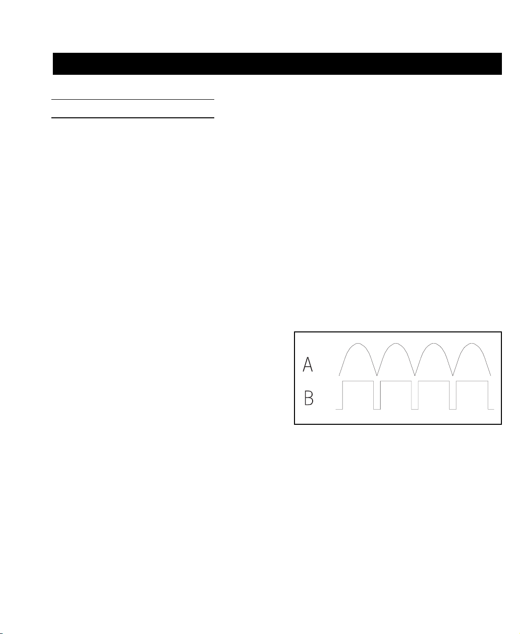
ZERO CROSSOVER DETECTOR
Comparator U8D is used as a zero crossover detector. AC
voltage from the transformer is rectified by diodes CR3 and
CR4 to produce a rectified unfiltered voltage signal at U8D
pin 11 (Fig 1 signal “A”). Signal “A” is compared with a
reference voltage to produce a low going signal at the time
period that the AC voltage is crossing zero volts (Fig 1
Signal “B”). Signal “B” at U8D pin 13 is the zero crossover
signal that is used to enable the triggering circuits of the
triacs at the zero crossover point.
Figure 1. Zero Crossover Detector
RESET, WATCHDOG, AND BROWNOUT CIRCUITS
Comparator U8B is used as the reset and brownout detector. When power is first turned on, the unregulated +14
Vdc charges C23 through R37 until voltage on C23 passes the 2 Vdc ref. voltage at U8B pin 6. The output of
U8B (pin 1) will then go high and turn off Q4 which will remove the reset from the microcontroller. If the
unregulated +14 Vdc falls below 6.8 Vdc the U8B will detect a brownout condition and continuously apply a
reset to the microcontroller.
Comparator U8A along with Q3 comprises the watchdog circuit. The microcontroller will supply a pulse stream
out of U3 pin 17 if the program is executing properly. If the program fails, the pulse stream will stop pulsing Q3
on and allow C21 to discharge causing U8A output (pin 2) to go low and turn on Q4, resetting the
microcontroller. When the reset is applied to the microcontroller, R3 provides a feedback into the watchdog
circuit to turn on Q3 and release the reset so that the microcontroller may restart its program.
3
Page 5

MICROPROCESSOR PCB ASSEMBLY
DISPLAY DRIVER
The LED display is multiplexed under software control. The power is supplied to the anodes for about 2.8 ms out
of the 11.11 ms, from the driver transistors (Q13-Q16). The driver transistors are controlled from pin 36 through
pin 39 of U3 (microcontroller). The information for the cathodes of the display is supplied through driver U5 and
U6-10 with the current limited by RN5. Information to the cathode’s drivers is supplied from the microcontroller
port 2 (U3 pin 21-28).
VACUUM PUMP DRIVER
The vacuum pump driver is comprised of transistors Q1 and Q17 which are controlled from both the
microcontroller (U3 pin 13) and the handpiece switches. When a switch is activated low, base current will flow
through Q1 base and R13. Q1 will turn on which in turn will turn on Q17 applying power to the motor of the
pump. At the same time the voltage at U3 pin 13 will go low, letting the program know that a switch has been
activated. The program will let the motor run at +28 Vdc for 150 ms and then it will start chopping the voltage at
a 2KHz rate by bringing pin 13 low and cutting off the base voltage of Q1. When the switch is released the
microcontroller will read pin 13 between chops (to see if the pin is not being held low by the switch) if pin 13 is
high, the microcontroller will reset the pump state to off (pin 13 held high). Although Q1 may fail if the
handpiece shorts and AC voltage is fed into the switch input, the zener diode CR8 will protect the
microcontroller.
BUZZER
U8C comparator forms a 2.05KHz square wave oscillator that drives Q21, which in turn drives the audio
transducer (LS1) at its resonant frequency. The driver is controlled by the microcontroller (U3 pin 11) holding
the base of Q21 low to turn it off. The RESET will also hold the driver transistor (Q21) off through CR5.
TRIAC DRIVER
Output to the triac drivers takes place on the back edge of the fourth digit display signal. Before turning off the
digit four display, the data on port two of the microcontroller is changed to the triac data and then turns digit four
off (signal going high), which clocks the triac data into U7. U7 is an eight bit latch that holds the triac
information. The output of the latch is enabled with the zero crossover signal which allows any output that has a
high latch within to turn on the associated triac. The microcontroller (U3) output from pin 10 will allow the
microcontroller to turn off all triacs at once through CR1. The high signals from U7 drive inverter U6 to turn on
the transistors that drive the current into the gates of the triacs. Each power triac driver has two drive transistors
to allow the triacs to be triggered from a negative voltage, so that the trigger will be in quadrant two, and quadrant
three. R11 is in series with the auxiliary triacs to limit the output current if a handpiece is plugged into the
auxiliary outputs.
4
Page 6

MICROPROCESSOR PCB ASSEMBLY
RTD CONSTANT CURRENT SOURCE AND CHANNEL MULTIPLEXOR
U9A makes up a constant current source that provides the current excitation for the RTD (in the connected
handpiece). The current is multiplexed to one of six RTDs to be measured. U9B amplifier feeds back the RTD
voltage to modify the constant current source to correct for the non-linearity of the RTD. U11 is a dual eight
channel multiplexor under control from the microcontroller (Mux A - Mux C signals). The multiplexor will
switch the constant current source to each of the RTDs and switch the RTDs voltage up to the analog to digital
converter (U10). CR9 and CR10 are in series with the multiplexor power inputs so that if the heater voltage feeds
back onto the RTD input, the voltage will be fed through the input diodes of the multiplexor; and the power rail
will float up to the input voltage and protect the chip (U11) from damage. Channel seven and eight of the
multiplexor switch in the two very high precision calibration resistors every four minutes to allow the
microcontroller to dynamically re-calibrate the RTD measuring circuits. R48 is the low calibration resistor (32°F),
and R50 is the high calibration resistor (987°F).
ANALOG TO DIGITAL CONVERTER
U10 is a dual-slope-integrating analog to digital converter front end. Under control from the microcontroller
(ADC A and ADC B signals), the dual-slope-converter will integrate the input for 16.6 ms into C25 and time the
deintegration to the reference voltage. The microcontroller will then use the two times, and the reference voltage,
to calculate the temperature of the RTD.
KEYBOARD INPUTS
The microcontroller (U3) drives the keyboard directly by providing the row drive (low signal) to the keyboard out
of pin 1 and pin 2. After a row has been selected, the microcontroller will read the keyboard data from pins 3, 4,
and 5.
EEPROM MEMORY
U4 is a 1024 bit Serial Electrically Erasable Programmable Memory. The microcontroller (U3) interfaces with
the memory through a serial interface using U3 pin 14 to select the memory chip, U3 pin 15 to clock the data into
the chip, and pin 16 to supply and read the data.
5
Page 7

MICROPROCESSOR PCB ASSEMBLY
ERROR CODES
There are certain error codes that may show up on the Digital Readout (display), if the program detect a fault
within the system. These Digital Readout errors are listed below with the probable cause (fault) and the probable
repair solution.
1. “ E “ in the middle of the Digital Readout. This error indicates an error on power-up when the system
program is checking the Random Access Memory or when comparing the sum-check against the store
sum-check. The microcontroller (U3) will require replacement.
2. “E-1” on the Digital Readout. This error indicates that the system program has detected a high
resistance on the sensor input (RTD open). Check the handpiece, J1 connector, RTD Constant current
source, channel multiplexor, and Analog to Digital converter.
3. “E-2” on the Digital Readout. This error indicates that the system program has detected a low
resistance on the sensor input (RTD shorted). Check the handpiece, J1 connector, RTD Constant
current source, channel multiplexor, and Analog to Digital converter.
4. “E-3” on the Digital Readout. This error indicates that the system program has detected an RTD
resistance on the sensor input greater then the referenced resistance for 1000°F, but less then the
resistance required to cause an “E-1” error (Digital Readout overflow). Check the handpiece, J1
connector, RTD Constant current source, channel multiplexor, and Analog to Digital converter.
5. “E-4” on the Digital Readout. This error indicates that the system program has detected an RTD
resistance on the sensor input lower than the referenced resistance for 32°F, but higher than the
resistance required to cause an “E-2” error (Digital Readout underflow). Check the handpiece, J1
connector, RTD Constant current source, channel multiplexor, and Analog to Digital converter.
6. “E-5” on the Digital Readout. This error indicates an incorrect resistance for the calibration resistors
(R48 and R50). Check the calibration resistors R48 and R50, RTD Constant current source, channel
multiplexor, and Analog to Digital converter.
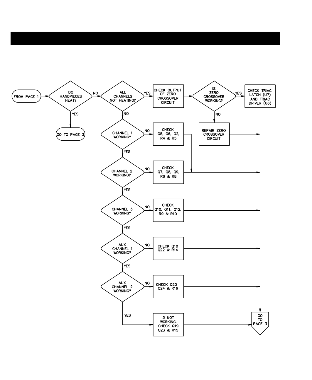
FLOW CHARTS
The following Flow Charts should be used to determine the source of the Microprocessor board malfunction
down to a circuit area or component level.
6
Page 8
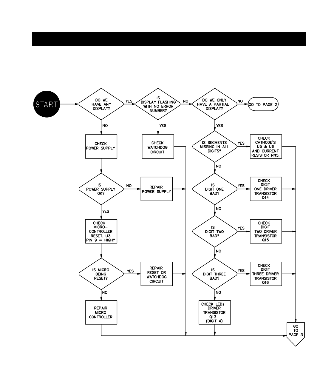
PAGE 1 OF 3
MICROPROCESSOR PCB ASSEMBLY
Figure 2. MicroProcessor PCB Troubleshooting
7
Page 9
MICROPROCESSOR PCB ASSEMBLY
PAGE 2 OF 3
Figure 2. MicroProcessor PCB Troubleshooting Cont'd
8
Page 10
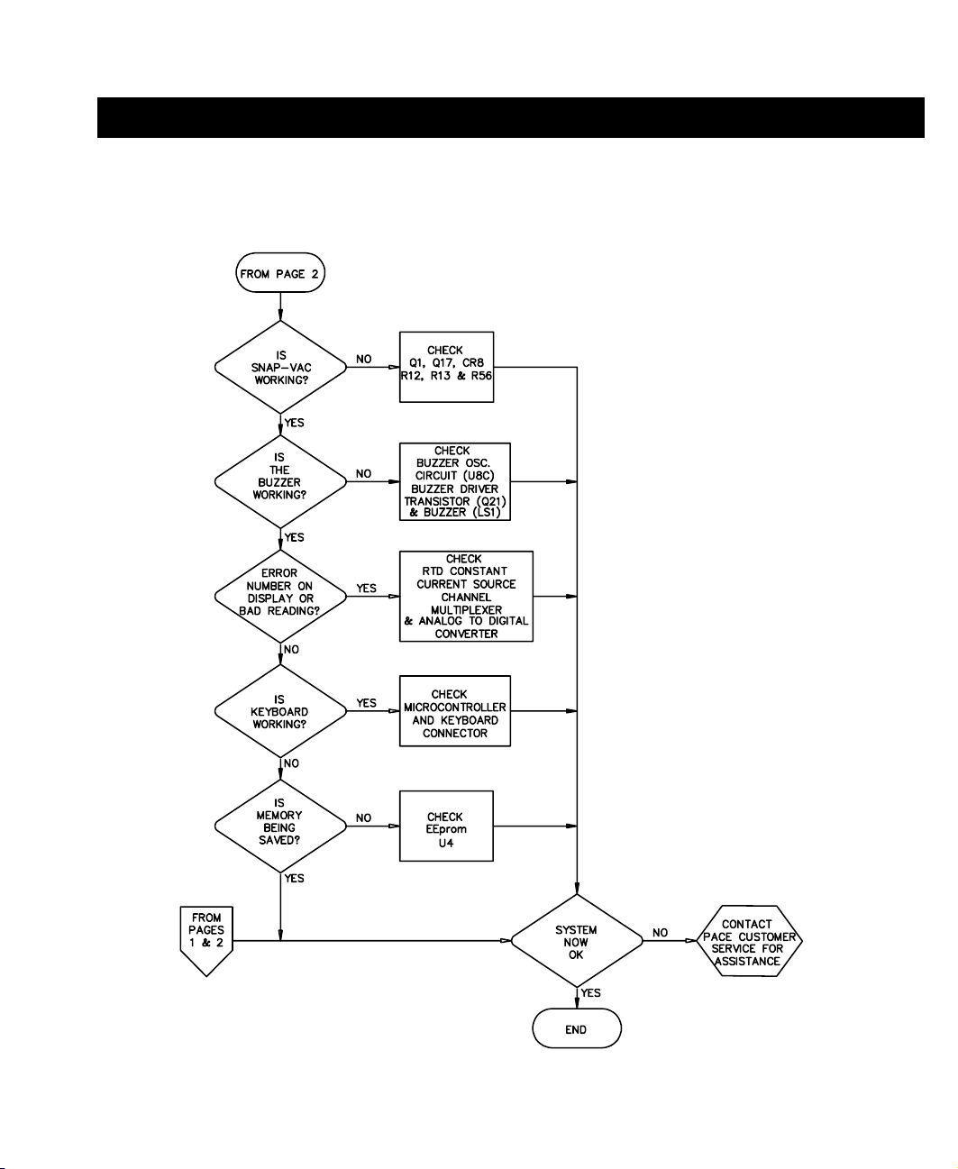
PAGE 3 OF 3
MICROPROCESSOR PCB ASSEMBLY
Figure 2. MicroProcessor PCB Troubleshooting Cont'd
9
Page 11

MULTIFUNCTION PCB ASSEMBLY
THEORY OF OPERATION
GENERAL DESCRIPTION
The PACE Multifunction Board (P/N 6020-0074) is used in the PPS 400 power source to provide status and
control for Pulse Heat, Pulse Plate, Paste Dispenser, Pik-Vac, and MicroChine functions. The board interfaces to
front panel controls and indicators via wire harnesses. It also interfaces to power supply voltages, the Pulse Heat
transformer, Pik-Vac vacuum pump, and Paste Dispenser motor pump assembly.
Refer to “Multifunction PCB Assembly Schematic” & “Wiring Diagram” of this manual or PACE schematic
5000-0283 and wiring diagram 5000-0284 for circuit and interconnect information when reading this document.
POWER SUPPLY
All supply voltages are routed on-board via wire harness connected at J31. The board operates from dual,
complementary, unregulated 14Vdc supplies and regulated +5Vdc. The complementary +14Vdc and -14Vdc are
produced by a 21 VCT transformer, bridge rectifier, and filter capacitors - all off-board and chassis-mounted.
Regulated +5Vdc is produced on the 6020-0072 PPS 400 Microprocessor (controller) Board and routed onto the
Multifunction Board at J31-5. The 21 VCT transformer secondary voltage, center tap, and chassis ground also
route on-board at J31.
PULSE HEAT SECTION
GENERAL
Pulse Heat circuitry controls the operation of low-voltage, high-current hand pieces such as Lap-Flo and
ThermoPart tools. The circuit phase-fires the line-voltage primary winding of the Pulse Heat transformer only
when the foot pedal selector switch is set to PH and the foot pedal is pressed. The transformer secondary directly
drives a Pulse Heat hand piece connected to front panel low-voltage AC output terminals. The effective
handpiece power level is set by adjusting the Pulse Heat control potentiometer. The Pulse Heat LED lights green
whenever the foot pedal is pressed while the selector switch is set to PH.
If the Pulse Heat output of a power source is coupled to another unit’s Pulse Heat output, U10, Q25, and possibly
the transformer may be damaged.
10
Page 12

MULTIFUNCTION PCB ASSEMBLY
CIRCUIT OPERATION
ZERO-CROSSING DETECTOR
Diodes CR17 & CR18 provide full-wave rectification of the main power transformer’s center-tapped secondary
voltage. The rectified voltage is applied to the voltage divider comprising R72 & R69, after transformer phaseshift compensation by C37. The voltage is divided down from about 10 VAC to 5VAC and applied to U6A-3,
where it is compared to 316 mVdc at U6A-2. When the amplitude of the AC signal at U6A-3 is less than 316
mVdc, U6A-1 output is low. When the AC signal at U6A-3 rises above 316 mVdc, U6A-1 output is high - the net
effect being the production of a train of narrow, negative-going, zero-crossover detection pulses at twice line
frequency.
RAMP GENERATOR
Each zero-crossing pulse forward-biases CR14, momentarily discharging C29 through R68 to a diode drop less
that the buffered reference voltage from U6B-7. With C29 discharging, the summing-junction current imbalance
at U6C-9 forces U6C-8 output high. The output remains high until the zero-crossover interval ends. At that time,
current entering the summing junction at U6C-9 through R25 and C29 drives output U6C-8 low at a constant rate.
The result is production of a periodic ramp (sawtooth) waveform. R61, U3A, CR7, R20, R21, C23 and U3B
drive U6C-9 through R25, compensating for line frequency differences and ensuring that U6C-8 output waveform
transitions from near ground to the positive supply rail.
PULSE-WIDTH MODULATION CONTROLLER AND LINE INTERFACE
The ramp waveform from U6C-8 is applied to U6D-13, where it is compared against the Pulse Heat control
voltage (set point). The set point voltage is applied to U6D-12 if the foot switch is closed. When the foot switch
is first closed, R71 & C36 slowly charge U6D-12 to the set point voltage, providing transformer “soft start”. The
set point voltage is compared against the ramp waveform at U6D-13, providing pulse-width modulated output at
U6D-14. The pulse-width modulated output of U6D-14 drives U10-1 through current-limiting resistor R70.
Snubber R103 & C35 attenuate foot switch-generated EOS/ESD transients. CR22 protects the optocoupler LED
from switching transients that exceed its reverse voltage rating. U10 triac conducts when the input LED is active,
turning on power triac Q25. R122 & R123 provide gate current limiting. When Q25 turns on, line voltage at
J34-1 is switched to the Pulse Heat transformer via J34-2. C50, C51, R124, and MOV1 protect the triac circuit
from false triggering or breakdown due to line transients.
11
Page 13

MULTIFUNCTION PCB ASSEMBLY
PULSE PLATE SECTION
GENERAL
Pulse Plate circuitry controls operation of SwaPlating electrodes. The Pulse Plate section of the front panel has
two banana jacks to accommodate plating electrodes, a control potentiometer for setting electro-cleaning &
plating voltages, and an LED to indicate status.
CIRCUIT OPERATION
PLATING VOLTAGE
Diodes CR23 & CR24 provide full-wave rectification of the main power transformer’s center-tapped secondary
voltage (10.5VAC1 & 10.5VAC2, respectively). The resultant unregulated, unfiltered, “pulsating” DC is used by
the Pulse Plate circuit to perform electro-cleaning and plating functions.
PWM CONTROLLER
U3D is the Pulse Plate setpoint comparator. The same periodic ramp waveform (saw tooth) used for Pulse Heat
PWM control is fed to U3D-13 and compared to the U3D-12 setpoint voltage. When the front panel selector
switch is set to PP and the foot switch open, the control potentiometer CW terminal (J32-16) floats, applying +14
Vdc as the setpoint voltage and forcing U3D-14 output high. When the foot switch is closed, the control
potentiometer CW terminal is grounded and the pot wiper voltage is applied to U3D-12 as the setpoint voltage.
Lower setpoint voltages increase the time the output is low (i.e. higher duty cycle) during the ramp waveform
period. Low output at U3D-14 forward biases CR8, turning on Q24 through current-limiting resistor R23. While
Q24 is on, pulsating DC current flows through the transistor out to the load via connector J33, the front panel “+”
and “-” DC output jacks, and the SwaPlating tools. Normal load current flows unless there is a “short-circuit”.
12
Page 14

MULTIFUNCTION PCB ASSEMBLY
FOLDBACK CURRENT LIMITING
Foldback current-limiting is provided by the circuit comprising R118, R119, R120, R121, C49, CR26, Q18 and
Q19. The typical “knee” value where foldback current limiting occurs is 3.4 A, DC average. Under short-circuit
conditions, the average DC load current is typically less than 400 mA.
STATUS LOGIC AND LED DRIVE
The status logic and Led drive circuit comprises U9, Q5, Q11, Q12, R92-R99, C33, CR21, J32-7, J32-19, and
J32-20. The Pulse Plate LED lights when the front panel selector switch is set to “PP” and the foot switch closed.
During normal plating operation, Q5 is off and U9A-2 is pulled up to +14 V through R93, driving U9A-3 low.
The low output is applied to U9B-5 through R94, driving U9B-4 inverter output high. The inverter output drives
Q12 base through R97, turning off Q12 and the red LED at J32-20. The inverter output also is applied to a
second inverter, U9C-8, which outputs low at U9C-10, turning on Q11 through R96. In the on state, Q11 turns on
the green Pulse Plate LED through R99.
In the event of an over-current condition, the foldback current-limiting circuit activates, and Q19 is on, driving
Q5 base through R92. Q5 turns on, pulling U9A-2 low. U3D-14 PWM output is applied to U9A-1. The low
portion of U3D-14 PWM output drives U9A-3 high. High output from U9A forward biases CR21, rapidly
charging C33 through R95. The resultant high at U9B-5 drives U9B-4 output low. The low signal turns on Q12
through R97, and the red Pulse Plate LED through R98. The low signal is also applied to inverter U9C-8, turning
off Q11 and the green Pulse Plate LED. During the high portion of the PWM signal, U9A-3 is low and CR32 is
blocking. C33 begins slowly discharging toward ground through R94. The large time constant of C33 and R94
ensure that a logic high is maintained at U9B-5 throughout the remainder of the period of U3D-14 PWM output.
The high at U9B-5 keeps the red Pulse Plate LED on as described above. When the over-current condition is
removed, the foldback current limiting circuit turns off, Q5 turns off, and the green Pulse Plate LED lights again
as described above.
13
Page 15

MULTIFUNCTION PCB ASSEMBLY
PIK & PASTE SECTION
THEORY OF OPERATION
GENERAL
The Pik & Paste section consists of circuits that control operation of the Pik-Vac vacuum pump and the Paste
Dispenser paste pump and solenoid valve. The Pik-Vac has an on/off switch, LED, and vacuum fitting for a
component pick-up hand piece (vacuum wand). The Paste Dispenser has a switch for selecting timed or
continuous dispensing, a control potentiometer for setting dispensing time, a status LED, and quick-connect
fitting for connection of a syringe containing solder paste, adhesive, or other material.
PIK-VAC CIRCUIT OPERATION
The Pik-Vac pump is connected between J31-8 and J31-2, and operates from 21 VAC. The pump operates when
the front panel Pik-Vac switch is closed, completing the circuits connecting the pump and Pik-Vac LED and the
21 VCT transformer secondary. With the Pik-Vac switch closed, 21 VAC is rectified by CR27, turning on the
green Pik-Vac LED through current-limiting resistor R125. CR27 provides LED reverse-voltage breakdown
protection. R126, R127, and C52 snub switch transients and reduce EOS/ESD in the system.
PASTE DISPENSER CIRCUIT OPERATION
RECYCLE TIMER
When the front panel selector switch is set to “PD”, +14 Vdc is supplied to J32-24 from J32-32. R65 and C19 are
connected to J32-32 and oscillator/timer IC U4’s Vcc pin. Vcc is connected to the MODE and Q/Q* pins,
configuring the timer to output high initially after reset and to operate in the recycle mode. C19 charges up and
powers U4 each time the selector switch is set to “PD”. U4-5 is grounded, enabling auto reset, and the chip resets
all internal counters at power-up. U4 oscillator frequency is 8.7 Hz, nominal, and is set by R26 and C5. Time
select inputs A and B are used to determine durations of low and high output at U4-8. The B time select input,
U4-13, is connected to ground. The A time select input, U4-12, is connected to the timer output, U4-8, through
R66. When a change of state occurs at the OUT pin, U4-8, R66, and C24 delay the new voltage level’s
application to U4-12, the A time select input, to allow for internal settling.
14
Page 16

MULTIFUNCTION PCB ASSEMBLY
When power is applied to U4, the timer automatically resets itself, and its OUT pin, U4-8 goes high. The B time
select input is low, and the A select input goes high due to its connection to U4-8. This combination of time
select inputs (along with MODE and Q/Q* inputs already discussed) programs the timer to output high for 256
counts, approximately 14 seconds. After 256 counts, the output goes low, selecting U4’s internal ripple counter
output for 8192 counts. Since 256 counts already have occurred in the internal ripple counter, the timer outputs
low for the number of counts remaining to reach 8192, 7936 counts, approximately 7 minutes and 36 seconds.
Thereafter, the cycle automatically repeats itself. The output goes high for 14 seconds, outputs low for 456
seconds, then repeats. This cycle will continue until the front panel selector switch is set to a position other than
“PD”, or the paste dispenser is activated by foot switch closure in either the timed or continuous mode, thereby
forcing a reset through U4’s MR (master reset) pin, U4-6.
PASTE DISPENSER PUMP DRIVE
The paste dispenser pump operates from two motor voltages. The motor is started with full 28 Vdc. This “kickstart” voltage provides the additional power required by the motor when starting up against a pressurized pump
and reservoir. The duration of the motor “kick-start” interval is established by C38 and R85. After the “kickstart” interval ends, 28 Vdc is replaced by a pulse-width modulated “run” voltage. This voltage operates the
pump after motor start-up. The “run” voltage is 11 Vdc avg.
The paste dispenser pump operates whenever U4-8 is at a logic high. When U4-8 output transitions high, the
signal is applied directly to U7C-8 and coupled through C38 to U8D-13 via R86. C38 and R85 establish the
duration of the motor “kick-start” interval. The high at U8D-13 drives U8D-11 low, turning on Q20 through R83.
Current flows through Q20 collector out to the paste pump connected between J31-12 and J31-10. The pump is
driven with approximately 28 Vdc. The low output from U8D-11 also routes to U7C-9. With both input
terminals at different logic levels, U7C output is driven high. The high signal charges C4 through R24. When C4
charges up, U3C-9 will momentarily go a little more positive than U3C-10, forcing U3C-8 low. When R85 has
discharged C38 to near ground (40ms, nominal), the combination of logic low signals at U8D input terminals
drives U8D-11 high, turning off Q20 and the paste dispenser pump. The high output from U8D is applied to
U7C-9, forcing U7C-10 low. U7C-10 low output discharges C4 through R24 and R64. When the voltage across
C4 drops to a little less than that at U3C-10, U3C-8 again goes high. The high is applied to U8D-12, driving
U8D-11 low. The low at U8D-11 provides base drive through R83 to Q20, turning on the paste pump. R24, C4,
and R64 will continue charging and discharging in this manner so long as U4-8 output is high. This provides
PWM control of Q20 and the pump. The duty cycle is approximately 40% with a PWM frequency of about
6kHz. The pump voltage is about 11 Vdc avg.
15
Page 17

MULTIFUNCTION PCB ASSEMBLY
CONTINUOUS MODE OPERATION
When the TIMED/CONT switch is set to “CONT” and the FOOT PEDAL selector switch to “PD”, pressing the
foot pedal makes a closure to ground at J32-17, turning on Q9 through R87. Q9 collector goes high, providing
base drive through R107 to solenoid driver transistor Q21. Q21 turns on, activating the solenoid valve connected
between J31-13 and J31-14 by providing a path to ground. The NC valve opens, gating the paste dispenser pump
and reservoir air supply to the front panel “PD” quick-connect. Concurrently, the high at Q9 collector is applied
to timer U4-6 master reset input through R28, resetting the timer. The timer output goes high, initiating PWM
drive of the paste dispenser pump as previously described. As long as the foot pedal switch is pressed, the closure
to ground at J32-17 is maintained and the pump and solenoid valve are active. When the foot pedal switch is
released, the high reset signal is removed from U4-6, and timer output U4-8 is high for 14 s, driving the pump
and recharging the reservoir.
TIMED MODE OPERATION
When the “TIMED/CONT” switch is set to “TIMED” and FOOT PEDAL selector switch to “PD”, pressing the
foot pedal makes a closure to ground at J32-29. The resultant low is coupled to the trigger input, U5-2, of the
‘7555 timer through C7. The timer output terminal, U5-3, goes high, turning on the solenoid valve by driving
Q21 base through R32 and R107. U5-3 high output also turns on the paste dispenser pump by driving its master
reset input, U4-6, through R32 and R28. The ‘7555 timer output remains high, driving the pump and solenoid
valve circuits for the time established by the resistance setting of a logarithmic pot between terminals J32-14 and
J32-34. The ‘7555 timer’s chief function is to provide timed gating of air to the attached dispensing hand piece
by accurately controlling its ON time. The timer output initiates paste dispenser pump turn-on at the same time as
the solenoid valve, but once the ‘7555 timer output goes low and the solenoid valve closes, the paste dispenser
pump continues to run for approximately 14s to replenish the reservoir. The pump will periodically recycle,
automatically recharging the reservoir. Dispensing only can occur when the solenoid valve is activated and that
occurs only when the foot pedal has been pressed.
R102 establishes a minimum on time when the log pot is set to its minimum resistance value. The trigger circuit
comprises snubber R33 & C8, and the trigger network of R30, C7 and R31. R34, C25, and CR13 form a poweron reset circuit. R35-R38 is a network with factory-set pot to improve timer accuracy by shifting the ‘7555 timer
internal switching threshold.
16
Page 18

MULTIFUNCTION PCB ASSEMBLY
STATUS LOGIC AND LED DRIVE CIRCUITS
Paste dispenser status is determined by logic gates U7A, U7B, and U8C. R78, R80, R82, R84, Q6, and Q7
provide Status LED drive. There are three status conditions: LED off, LED green, LED amber. When the Paste
Dispense section is not selected or the pump is idle and not recharging, U4-8 and U5-3 are low. The low from
U4-8 is applied to inverter U7A, which outputs high, keeping transistor Q6 and the green LED off. U5-3 low
output is applied to inverter U8C through R32, driving U8C-10 high. The high is applied to U7B-6. The
remaining input terminal is fed a low by U4-8, driving U7B-4 high, turning off Q7 and the red LED. If the Foot
Pedal Selector Switch is set to “PD” for paste dispensing, but the foot switch is open and the pump is recharging
the air reservoir, U4-8 output is high and U5-3 output is low. U4-8 high output is inverted by U7A, producing a
low at U7A-3, turning on Q6 through R80. Q6 turns on the green PASTE DISP LED through R78.
Concurrently, U8C inverts U5-3 low output, driving U8C-10 high. The resultant high at U7B-6 paired with the
high at U7B-5 from U4-8, drives U7B-4 low. This low output turns on Q7 through R82. Q7 turns on the red
PASTE DISP LED through R84. Since the red and green PASTE DISP LEDs are both on and contained within
the same T1-3/4 package, the LED lights amber, indicating that the pump is recharging the reservoir. In the event
that the foot pedal is pressed in either the timed or continuous operational mode, a high is applied to inverter
U8C. In continuous mode, the high is produced by Q9; U5-3 drives the inverter through R32 in timed mode. The
high input at inverter U8C produces low output which is applied to U7B-4. U4-8 is driven high by application of
a high at its master reset input (from Q9 if continuous mode, U5-3 if timed). The high output from timer U4-8 is
applied to inverter U7A and pin 5 of U7B. U7A output is low, turning on transistor Q6 through R80, and the
green PASTE DISP LED through R78. The combination of logic high and low inputs at U7B, produce high
output at U7B-4, keeping Q7 and the red PASTE DISP LED off. Hence, the PASTE DISP LED is green ,
indicating that a dispensing cycle is in progress.
17
Page 19

MULTIFUNCTION PCB ASSEMBLY
MICROCHINE SECTION
GENERAL
The MicroChine section consists of circuitry that interfaces to and controls operation of the MicroChine
handpiece and probe brake patch cord. The Micro-Chine section has a front panel control potentiometer for
setting shaft rotational speed (RPM), a handpiece connector, Probe Brake banana jack, and Status LED. The
MicroChine handpiece is used for drilling, milling, probing and abrading operations.
CIRCUIT OPERATION
CLOSED-LOOP CONTROL CIRCUIT
The MicroChine shaft speed is resolved by measuring the back EMF generated by the motor. The motor is driven
by pulse width modulated (PWM) voltage. During each interval when the PWM motor-drive voltage is off, the
motor coasts, producing a back EMF or “generator” voltage. The back EMF voltage is proportional to motor
speed. This generator voltage is scaled by the voltage divider comprising R42 and R43, and filtered by C21.
When back EMF is generated, CR2 is forward biased, and the scaled, diode-offset back EMF signal applied to op
amp U1A-3. The op amp is configured as a voltage follower, buffering the back EMF signal and applying it
through R4 to the summing junction of error amplifier U1D-13. The summing junction detects differences
between the back EMF signal and the control pot RPM setting. R1 and R2 provide summing junction offset
current compensation. R2 is set at the factory during calibration. The Variable Speed Control pot ends are
connected in parallel with 18V zener diode CR11 at J32-1 and J32-31. The wiper voltage is routed on board via
J32-28 and applied to R44, generating the set point current at the summing junction. Whenever the summing
junction detects that the motor speed is less than the setpoint, U1D-14 output is driven high. U1D output is
applied to comparator U1B-5 through the network comprising R5-R10, C12, C13, CR3, and CR4. When the
handpiece is just turned on, R7 and C13 provide “soft-start” of the motor by slowly charging up to the error
voltage. The divider consisting of R8-R10 and diodes CR3 and CR4 clamp U1D output over a narrow voltage
range, limiting the error voltage. This conditioned error voltage signal provides improved motor response to
changing shaft load, i.e., transients, and produces a “smoother” PWM output when U1B-5 is compared to the
triangle waveform at U1B-6. The triangle waveform at U1B-6 is produced by the ramp generator comprising
U1C, R47-R50, and C22. The signal is applied to U1B-6 through R41, and is a 300 Hz, nominal, signal varying
from -8V to -2V. As the error voltage at U1B-5 increases, so does the width of the positive-going pulses at the
comparator output, U1B-7. The comparator output is clamped by CR10, providing Q14 base-emitter junction
reverse breakdown voltage protection. When the comparator output is high, it provides base drive to Q14 through
R51. If the MicroChine handpiece switch is closed, or the Foot Pedal Selector Switch is set to “MC” and the foot
pedal switch closed, Q13 is off and does not clamp Q14 base to ground. Thus, Q14 is permitted to turn on each
time positive-going PWM pulses are applied unless the PROBE BRAKE latch is activated.
18
Page 20

MULTIFUNCTION PCB ASSEMBLY
The PROBE BRAKE latch output, U2A-1 must be low for the MicroChine handpiece to run. The MicroChine
motor runs when the handpiece switch is closed, or the Foot Pedal Selector Switch is set to “MC” and the foot
pedal switch closed. When neither switch is closed and the PROBE BRAKE latch is off (U2A-1 output is low), a
+5V control signal is applied through R16 and R13 to Q2 base, turning on Q3 and forcing U1D-14 output low.
This shuts down PWM output from U1B after a slight delay (due to slew-rate and integrator effects) and thus, the
motor drive transistor Q22. The motor control signal also biases Q16 on through R111. Q16 turns on Q17
through R115. Q17 turns on brake transistor Q23 through R117, braking the free-wheeling motor when the
switch is released. The control signal also is applied to Q13 base through R108, turning on Q13. Q13 keeps Q14
off, clamping its base near ground. With Q14 off, Q22 base is pulled high through R105 and R109, cutting off
the motor driver transistor virtually as soon as the switch is released.
OVER-CURRENT DETECTOR/TORQUE LIMITER
Motor torque is monitored and limited by the over-current detector/torque limiter. This circuit comprises R113,
R110, R114, C47, Q15, R39, and CR1. Motor drive current flows through current-sense resistor R113.
Instantaneous voltage drop develops across R113, proportional to instantaneous current draw of the MicroChine
handpiece motor. The voltage across R113 is averaged by C47 and R110. Q15 acts as a comparator with a
threshold of approximately 0.6 volts. If high motor torque develops (due to overload), the average voltage across
C47 reaches 0.6 volts, and Q15 turns on. The collector voltage of Q15 forward-biases CR1, gating current
through R39 to the error amplifier summing junction U1D-13. The amplifier output then signals the pulse-width
modulator to slow down the motor, reducing motor drive current and torque.
19
Page 21

MULTIFUNCTION PCB ASSEMBLY
MICROCHINE SECTION CONT’D
PROBE BRAKE CIRCUIT
The PROBE BRAKE circuit comprises C2, C3, C16, C17, CR5, CR6, R15, R17-R19, R57-R60, R128, U2A, and
U2B. A voltage divider consisting of R17 and R18 provides low-voltage, low-current, safe excitation of a
workpiece connected to a test lead plugged into the front panel PROBE BRAKE Receptacle. The front panel
jack is connected to the divider via wire harness conductor terminating at J32-27. R128 provides input protection
of buffer U2B. The 200 mVdc divider voltage is buffered by U2B, and applied to probe brake latch U2A through
R60. Another voltage divider comprising R19, R58, and R59, applies a 100 mVdc reference voltage to U2A-3.
The latch output, U2A-1, is low and remains at that level until the J32-27 is pulled down below 100 mVdc. In a
typical application, this occurs when the MicroChine tip contacts the PROBE BRAKE test lead or part of a
workpiece to which it is connected. When the PROBE BRAKE input is pulled below the 100 mVdc reference of
the latch, it is applied through buffer U2B and R60 to U2A-2, the latch trigger input. The latch output goes high,
driving CR6 into conduction, and shifting the latch reference voltage well above the 200 mVdc excitation
normally applied by the buffer. Through this action, U2A output is latched high, even if the workpiece is
disconnected from the PROBE BRAKE Receptacle. The latch is cleared by first allowing the excitation voltage
to return to its 200 mVdc nominal value. Typically this is done by lifting the MicroChine handpiece away from
the workpiece, breaking contact between the PROBE BRAKE excitation voltage and ground. (Ground is
provided by any metallic MicroChine tip since the handpiece shaft is grounded.) Secondly, the handpiece or foot
switch must be released momentarily, coupling a high through C16 and CR5 to U2A-2, temporarily raising its
input voltage above the latch reference threshold voltage at U2A-3. This drives U2A output low, reverse-biasing
CR6, and re-establishing the 100 mVdc reference voltage at U2A-3.
The MicroChine handpiece PROBE BRAKE feature is supported by EOS/Chassis Ground being continuous with
DC Circuit Ground through PTC1. This keeps the MicroChine shaft at ground potential for probing and provides
fault protection in the event of a ground fault in the THERMAL MANAGEMENT CENTER (TMC) section of
the unit. If a ground fault causes the PTC to enter its high-resistance state, the PROBE BRAKE circuit and its
Status LED will activate and/or indicate.
In addition to the grounded shaft, the MicroChine handpiece incorporates a bifilar-wound choke and a transzorb
to minimize EOS/ESD transients.
20
Page 22

MULTIFUNCTION PCB ASSEMBLY
STATUS LOGIC AND LED DRIVE CIRCUITS
MicroChine operating status is indicated by a front-panel mounted tri-color Status LED. MicroChine status is
determined by the states of the handpiece and foot pedal switches, the probe brake latch, and the over-current/
torque-limiting circuit. During normal operation, either the MicroChine handpiece switch is closed, or the front
panel Foot Pedal Selector Switch is set to “MC” and the foot pedal switch closed, lighting the Status LED green.
When the torque-limiting circuitry is active, the LED is amber. The LED is red if the probe brake latch is on.
The status circuit which detects a handpiece or foot switch closure comprises R11, R54, Q1 and U7D. The
PROBE BRAKE latch output state is read by R76, R77, Q4, and U8A. Active torque-limiting circuitry is
detected by the network consisting of CR20, R91, C39, and R90.
During normal operation, the torque-limiter is off, pulling low U8B-5 through R90. Since the probe brake is also
off during normal operation. Q4 is off, and U8A inputs are pulled high through R77, driving U8B-6 low. With
both inputs low, U8B-4 output is at a logic high, keeping Q10 cut-off and the red Status LED off (J32-18).
When the PROBE BRAKE latch is on, base current flows through R76, turning on Q4, and pulling low U8A
inputs and U7D-12. The low at U7D-12, drives U7D-11 high, keeping Q8 cut off and the green Status LED (J32-
8) off. The low inputs of U8A drive its output to a logic high. U8B-6 is connected to U8A output. The logic high
applied by U8A to U8B-6, forces U8B out low, turning on Q10 through R88. Q10 collector voltage turns on the
red Status LED through R89, J32-18, and J32-26.
When the PROBE BRAKE latch is off and torque-limiting circuitry active, Q15 collector voltage forward biases
CR20, charging C39 through R91. The resultant logic high is maintained during PWM motor drive voltage off
periods by the large time constant of C39 and R90. The logic high from C39 is applied to U8B-5, forcing its
output pin low (U8B-4), and turning on Q10 and the red Status LED.
The green status LED is on through the same circuit operation described for normal operation. The combination
of simultaneously lit green and red Status LED produces an amber color.
The Status LED is off if the PROBE BRAKE latch and handpiece are off.
21
Page 23

MULTIFUNCTION PCB ASSEMBLY
FLOW CHARTS
The following Flow Charts should be used to determine the source of the Multifunction board malfunction down
to a circuit area or component level. Locate the chart that best describes the malfunction.
PULSE HEAT
Figure 3. Pulse Heat Troubleshooting
22
Page 24

PULSE PLATE
MULTIFUNCTION PCB ASSEMBLY
Figure 4. Pulse Plate Troubleshooting
23
Page 25

MULTIFUNCTION PCB ASSEMBLY
MICROCHINE
Figure 5. MicroChine Troubleshooting
24
Page 26

MULTIFUNCTION PCB ASSEMBLY
25
Page 27

PASTE DISPENSER
MULTIFUNCTION PCB ASSEMBLY
Figure 6. Paste Dispenser Troubleshooting
26
Page 28

MULTIFUNCTION PCB ASSEMBLY
27
Page 29

HS 150 CALIBRATION PROCEDURE
INTRODUCTION
The following procedure will enable the technician to accurately calibrate the control circuitry of the PACE
HS 150 (or HS 150E) system. Follow the procedure using the accompanying drawings as a guide.
System: HS150 P/N: 7040-0002
PROCEDURE
GENERAL DISSASSEMBLY
1. With the unit power turned off and unplugged from the AC supply, and cooled off to room
temperature, remove the Top Cover Screws. Remove the Top Cover from the unit.
Figure 7. HS 150 Parts Identification
2. Disconnect the two White varglass sensor leads from the White/Orange and White/Gray leads (refer to
Figure 8).
28
Page 30

HS 150 CALIBRATION PROCEDURE
PLATE TEMPERATURE CONTROL
3. Connect a 177.47 ohm resistance between the White/
Orange and White/Gray lead, and monitor the voltage
of the White/Gray lead with respect to the White/
Orange lead. This voltage will be called V1.
4. Move the shorting block on J14 pins 2 and 3 to J14
pins 1 and 2 (refer to Figure 8).
5. Turn the Plate Control and Probe Control knobs on
the front panel completely counter clockwise (refer to
Figure 7).
6. Plug the power cable into the AC supply, and turn the
Power Switch on.
7. Monitor the voltage at TP1 (refer to Figure 8) with
respect to the White/Orange lead. This voltage will
be called V3.
8. Adjust R36 until voltage V3 reads 5mV higher than
voltage V1.
9. Position the Probe/Plate Switch to "Plate" (refer to
Figure 7).
10. Position the °C/°F Switch to °C (refer to Figure 7).
11. Connect a114.68 ohm resistance between the White/
Orange and White/Gray leads.
12. Adjust R35 until the display reads 38.
13. Position the °C/°F switch to °F.
14. Adjust R34 until the display reads 100.
15. Connect a 177.47 ohm resistance between the White/
Orange and White/Gray leads.
16. Postion the °C/°F switch to °C.
17. Adjust R37 until the display reads 204.
18. Position the °C/°F Switch to °F.
19. Adjust R38 until the display reads 400.
20. Repeat steps 10 through 19 until there is no change in
the display at the calibration points.
Figure 8. HS 150 PC Board
If Probe Temperature Control calibration is not needed, skip to step 25.
29
Page 31

HS 150 CALIBRATION PROCEDURE
PROBE TEMPERATURE CONTROL
21. Verify that a 177.47 ohm resistance is connected between the White/Orange and White/Gray lead, and
monitor the voltage of the White/Gray lead with respect to the White/Orange lead. This voltage will
be called V1.
22. Verify that the Plate Control and Probe Control knobs on the front panel are completely counter
clockwise (refer to Figure 7).
23. Using a 3.5 mm plug, connect a 177.47 ohm resistance into the probe jack (refer to Figure 7).
Monitor the voltage across the resistance, center conductor with respect to the ground conductor. This
voltage will be called V2.
24. Adjust R39 until voltage V1 matches voltage V2 +/- .5 mV.
GENERAL ASSEMBLY
25. Turn unit off and unplug.
26. Reconnect the white varglass sensor leads to the White/Orange and White/Gray leads.
27. Move the shorting block on J14 pins 1 and 2 to J14 pins 2 and 3.
28. Apply glyptol (or other like locking substance) to trimpots 1 through 6.
29. Remount the Top Cover to the unit using the 2 Top Cover Screws removed in step 1.
30
 Loading...