

Page 1

PRC 2000 SYSTEMS
SERVICE MANUAL
Page 2

MANUAL NO. 5050-0344
REV. C
i
Page 3

PACE Incorporated retains the right to make changes to specifications contained herein at any time, without
notice.
Contact your local authorized PACE Distributor or PACE Incorporated to obtain the latest specifications.
The following are registered trademarks and/or servicemarks of PACE Incorporated, Laurel Maryland U.S.A. and
may only be used to identify genuine PACE products or services:
AdapTip, Arm-Evac, Cir-Kit, ComForm I, ConducTweez, CRAFT,
Dual Path, Flo-D-Sodr, FuseSet, HandiPik, HotSpot, LapFlo, MBT,
Micro Portable, MicroChine, MiniChine, Mini-Wave, PACE, Pacenter,
Ped-A-Vac, PETS, Pik-Vac, PRC, PRINT, Pro-Evac, Redi-Rak,
ResisTweez, SensaTemp, SMR, Snap-Vac, Sodr-Pen, Sodr-X-Tractor,
SR-3, SR-4, ST, StripTweez, SwaPlater, ThermoBand, Thermo-Drive,
ThermoJet, ThermoPart, ThermoPik, ThermoT weez, Tip-Evac, VisiFilter .
The following are trademarks and/or servicemarks of PACE Incorporated, Laurel Maryland U.S.A. and may only
be used to identify genuine PACE products or services:
Auto Off, Cubby-Vac, Datastore, Dust Evac, EKO, Lab Evac, MicroSpin,
PaceLink, PaceNet, Pik & Paste, Prep-Set, Pulse Plate, Spa-Kleen,
ThermoBond, TinSpin, TweezPik, Uni-Frame, V-A-N, Ventur-Evac.
Since 1958, PACE Incorporated has provided advanced technology training in all
aspects of hand soldering, rework and repair.
Additional copies of this manual or other PACE literature may be obtained from:
PACE Incorporated (301) 490 - 9860
Sales Administration (301) 498 - 3252 Fax
9893 Brewers Court
Laurel MD 20723-1990
©1995 PACE Incorporated, Laurel MD. All rights reserved. Printed in the U.S.A.
ii
Page 4

TABLE OF CONTENTS
TITLE PAGE
General Information ............................................................................................................................................... 1
Introduction ................................................................................................................................................. 1
Specifications............................................................................................................................................... 1
Parts Identification....................................................................................................................................... 4
Safety .................................................................................................................................................................... 16
Heading Guidelines ................................................................................................................................... 16
Precautions................................................................................................................................................. 17
Repair ................................................................................................................................................................... 19
Repair Procedure ....................................................................................................................................... 19
Service Hints.............................................................................................................................................. 20
Corrective Maintenance............................................................................................................................. 21
VisiFilter Element Replacement .......................................................................................................... 21
SensaTemp Handpieces........................................................................................................................ 22
MicroChine Handpiece ........................................................................................................................ 23
Power Source........................................................................................................................................ 25
Calibration ................................................................................................................................................. 30
Disassembly/Assembly.............................................................................................................................. 32
Disassembly ......................................................................................................................................... 32
Assembly.............................................................................................................................................. 37
Flow Charts................................................................................................................................................ 39
Power.................................................................................................................................................... 40
TMC ..................................................................................................................................................... 42
Pik & Paste ........................................................................................................................................... 44
MicroChine .......................................................................................................................................... 46
Pulse Plate ............................................................................................................................................ 48
Pulse Heat............................................................................................................................................. 50
Wiring Diagram ......................................................................................................................................... 52
Multifunction PCB Assembly Schematic.................................................................................................. 54
Microprocessor PCB Assembly Schematic............................................................................................... 60
Display PCB Assembly Schematic............................................................................................................ 64
Assembly Drawing .................................................................................................................................... 66
Air Hose Routing....................................................................................................................................... 68
Replacement Parts ................................................................................................................................................ 69
Power Source ............................................................................................................................................. 69
Power Source Accessories......................................................................................................................... 73
Handpieces................................................................................................................................................. 74
Handpiece Accessories .............................................................................................................................. 76
Manual Improvement & Comment Form ............................................................................................................ 77
iii
Page 5

TABLES & FIGURES
TABLE PAGE
Table I Heater Assembly Checkout Procedures.......................................................................................... 22
Table II MicroChine Handpiece Checkout Procedures................................................................................ 24
Table III Corrective Maintenance, Power Source ......................................................................................... 25
Table IV Power Source Replacement Parts ................................................................................................... 69
Table V Power Source Accessories .............................................................................................................. 73
Table VI Replacement Handpieces................................................................................................................ 74
Table VII Replacement Handpiece Accessories ............................................................................................. 76
FIGURE PAGE
Figure 1. Power Switch/Foot Pedal Selector Switch ....................................................................................... 4
Figure 2. Pulse Heat Section ............................................................................................................................ 5
Figure 3. Pulse Plate Section............................................................................................................................ 6
Figure 4. MicroChine Section .......................................................................................................................... 7
Figure 5. Pik And Paste Section....................................................................................................................... 9
Figure 6. Thermal Management Center Parts I.D. ......................................................................................... 12
Figure 7. Rear Panel Parts I.D........................................................................................................................ 15
Figure 8. VisiFilter Element Replacement..................................................................................................... 21
Figure 9. Connector Plug Wiring ................................................................................................................... 23
Figure 10. MicroChine Wiring......................................................................................................................... 23
Figure 11. Thermocouple Attachment.............................................................................................................. 31
Figure 12. Removing Rear Panel Screws......................................................................................................... 33
Figure 13. Removing Front Panel .................................................................................................................... 34
Figure 14. Removing Bolt Assemblies............................................................................................................. 35
Figure 15. Removing Power Source From Case .............................................................................................. 36
Figure 16. Power Flow Chart ........................................................................................................................... 40
Figure 17. Thermal Management Center Malfunction Flow Chart ................................................................. 42
Figure 18. Pik & Paste Malfunction Flow Chart ............................................................................................. 44
Figure 19. MicroChine Malfunction Flow Chart ............................................................................................. 46
Figure 20. Pulse Plate Malfunction Flow Chart............................................................................................... 48
Figure 21. Pulse Heat Malfunction Flow Chart ............................................................................................... 50
Figure 22. PPS 400, PPS 400J, PPS 400E Wiring Diagram ............................................................................ 52
Figure 23. MultiFunction PCB Assembly Schematic ...................................................................................... 54
Figure 24. Microprocessor PCB Assembly Schematic .................................................................................... 60
Figure 25. Display PCB Assembly Schematic................................................................................................. 64
Figure 26. Assembly Drawing ......................................................................................................................... 66
Figure 27. Assembly Drawing Cont'd.............................................................................................................. 67
Figure 28. Air Hose Routing ............................................................................................................................ 68
Figure 29. Power Source Replacement Parts ................................................................................................... 70
Figure 30. Power Source Replacement Parts Cont'd........................................................................................ 71
Figure 31. Power Source Replacement Parts Cont'd........................................................................................ 72
iv
Page 6

GENERAL INFORMATION
INTRODUCTION
The information contained in this manual will assist the technician in performing preventive maintenance and
repair of the PACE PRC 2000 Systems. For details on operation of the system, refer to the System Operation &
Maintenance Manual (PACE part number 5050-0313). If you encounter any difficulty operating or repairing
your system, call PACE Customer Service directly at Tel. (301) 490-9860 or FAX (301) 604-9215.
The PRC 2000 is a Process Control System for Universal Assembly and Repair of Electronic Assemblies. The
system combines the latest technology available for all types of component installation/removal, circuit board
preparation and repair into one self-contained workstation.
The SR-4 “Safety Rating” designation on the back panel is your assurance that the PRC 2000 meets or exceeds
all applicable civilian and military standards (including *MIL-STD-2000A, and *WS-6536), EOS/ESD and
worldwide electrical codes. *NOTE - Systems equipped with a special current limiting option (1 meg ohm tip
to ground resistance) comply with EN 100015-1. PACE refers to these systems as "Soft Ground Systems".
The PRC 2000 system is available using power sources in either the 100 VAC version, the 115 VAC version or
the 230 VAC version. The 230 VAC version system (production as of Sept. 1995) bears the CE Conformity
Marking which assures the user that it conforms to all the requirements of council directive EMC 89/336/EEC.
SPECIFICATIONS
POWER REQUIREMENTS
PPS 400 (PRC 2000 system): 115 VAC System - Operates on 97-127 VAC, 60 Hz. 400 Watts.
PPS 400J (PRC 2000J system): 230 VAC System - Operates on 90-115 VAC, 50/60 Hz. 400 Watts.
PPS 400E (PRC 2000E system): 100 VAC System - Operates on 195-264 VAC, 50/60 Hz. 400 Watts.
PHYSICAL PARAMETERS
Size: 35 cm W x 17.5 cm H x 23 cm D (13.75 in W x 6.9 in H x 9.25 in D)
Weight: 13.6 Kg (30 Lbs)
ENVIRONMENTAL REQUIREMENTS
Ambient Operating Temperature: 0°C to 50°C (32°F to 120°F).
Storage Temperature: -40°C to 100°C (-40°F to 212°F).
1
Page 7

GENERAL INFORMATION
THERMAL MANAGEMENT CENTER
VACUUM AND AIR
Measurements at Front Panel SNAP-VAC and PRESSURE Ports of power source.
Vacuum Rise Time : Evacuates 33 cc (2 cubic inch) volume
to 25 cm Hg. (10 in. Hg.) in 150 ms.
Vacuum: 51 cm Hg. (20 in. Hg.) (nominal)
Pressure: .48 Bar (7 P.S.I.) (nominal, "MAX" setting)
Air Flow: 13 SLPM (0.46 SCFM) maximum
HANDPIECES
Set T emperatur e Range
of SensaTemp Handpieces: 38°C to 482°C (100°F to 900°F) (see note).
Digital Readout Resolution: ± 1° (°C or °F)
Tip Temperature Stability: ± 1.1°C (± 2°F) at idle from Set Tip Temperature.
True minimum and maximum Operating Tip Temperatures may vary
depending on handpiece & tip selection.
EOS/ESD
Tip-To-Ground
Resistance: Less than 5 ohms.
AC Leakage : Less than 2 millivolts RMS from 50Hz to 500Hz.
PIK AND PASTE
Vacuum
(at PIK-VAC Port): 7.6 cm Hg. (3 in. HG.) min.
Pressure
(at PASTE DISP Port): 2.41 Bar (35 P.S.I.) min.
2
NOTE
Page 8

MICROCHINE
HANDPIECE
Nominal Output
Speed Range: 2,500 rpm, min. to 10,000 rpm, max.
Output T or que: 14 N•mm (2.0 inch-ounces), min.
Speed Regulation: +10/-15% over Line/Load range of 0 to 14 N•mm (0 to 2 inch-ounces)
Duty Cycle: Application Dependent. Continuous loading to maximum torque (Status
Shaft Run-Out at Collet: .13mm (0.005 inches) TIR (Total Indicator Reading) max.
EOS/ESD
Tip-To-Ground
Resistance: Less than 5 ohms.
GENERAL INFORMATION
from low line to high line voltage.
LED Amber in color) will cause the handpiece case to overheat.
Continuous heavy loading without a cooling period may cause damage
to the handpiece and/or the power source.
AC Leakage : Less than 2 millivolts RMS from 50Hz to 500Hz, min.
PULSE PLATE
Output Voltage Range: 0 - 10 volts unfiltered, full wave DC.
PULSE HEAT
Output Voltage Range: 0 - 2.3 VAC RMS
3
Page 9
GENERAL INFORMATION
PARTS IDENTIFICATION
SYSTEM
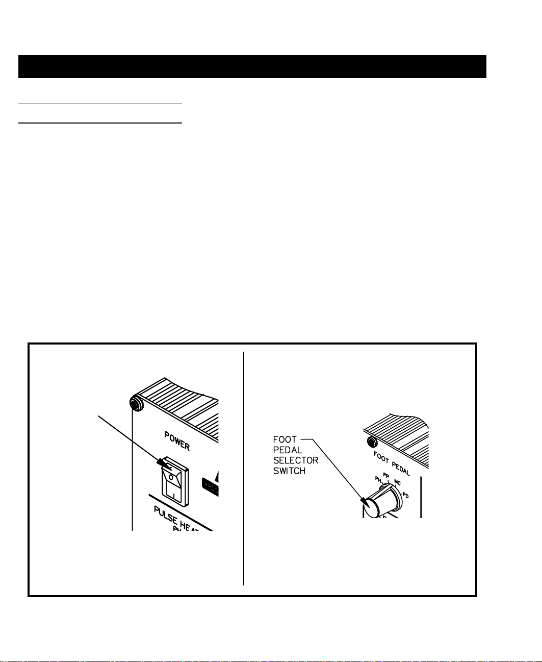
1. POWER SWITCH - Turns system ON (“1”) and OFF (“0”); controls input power to the system.
2. FOOT PEDAL SELECTOR SWITCH - Control knob provides foot pedal connection to Pik and
Paste (PD), MicroChine (MC), Pulse Plate (PP) or Pulse Heat (PH) features.
POWER
SWITCH
Figure 1. Power Switch/Foot Pedal Selector Switch
4
Page 10
GENERAL INFORMATION
FRONT PANEL FEATURES
PULSE HEAT
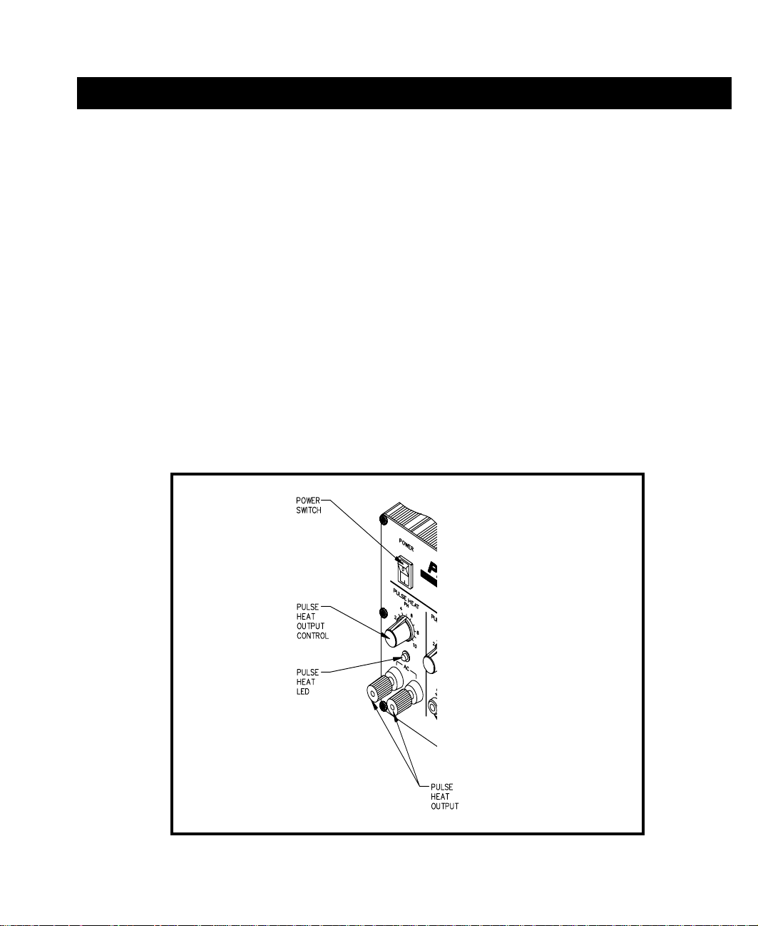
3. PULSE HEAT OUTPUTS - Low voltage AC power outputs for Low Voltage, Pulse Heat
handpieces.
4. PULSE HEAT OUTPUT CONTROL - Controls low voltage AC power at PULSE HEAT Outputs.
5. PULSE HEAT LED - Illuminates Green in color when power is applied (by foot pedal through
FOOT PEDAL Selector Switch) to the PULSE HEAT Outputs.
Figure 2. Pulse Heat Section
5
Page 11
GENERAL INFORMATION
PULSE PLATE
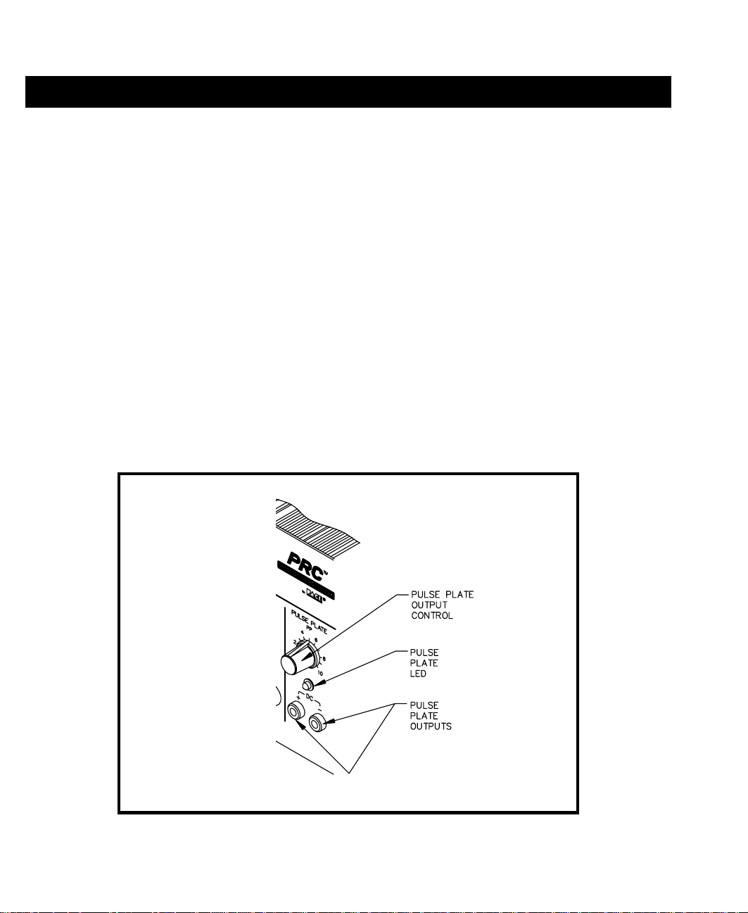
6. PULSE PLATE OUTPUTS - DC power connections for PACE SwaPlater plating system.
7. PULSE PLATE OUTPUT CONTROL - Controls DC power at PULSE PLATE Outputs.
8. PULSE PLATE LED - Illuminates Green to indicate when power is applied (upon foot pedal
actuation) at the PULSE PLATE Outputs. Illuminates Red if an overcurrent condition occurs during
plating.
Figure 3. Pulse Plate Section
6
Page 12
GENERAL INFORMATION
MICROCHINE
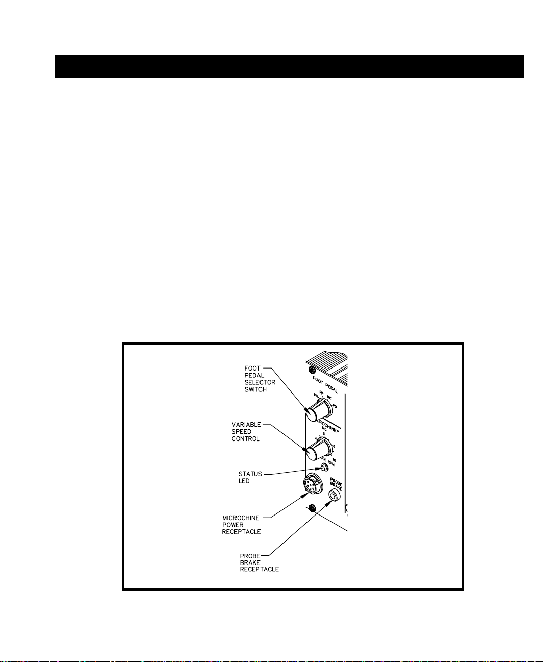
9. MICROCHINE POWER RECEPTACLE - Provides power, speed control, tip ground and finger
switch connection for the MicroChine handpiece.
10. VARIABLE SPEED CONTROL - Controls motor speed (2,500 - 10,000 RPMs) of MicroChine
handpiece.
11. PROBE BRAKE RECEPTACLE - Provides Probe Brake connection for the MicroChine Probe
Brake feature. See MicroChine portion of this manual for details.
12. STATUS LED - Illuminates Green to indicate MicroChine operation. Illuminates Amber if maximum
torque load is reached. Illuminates Red to indicate braking status when Probe Brake circuit is
activated.
Figure 4. MicroChine Section
7
Page 13

GENERAL INFORMATION
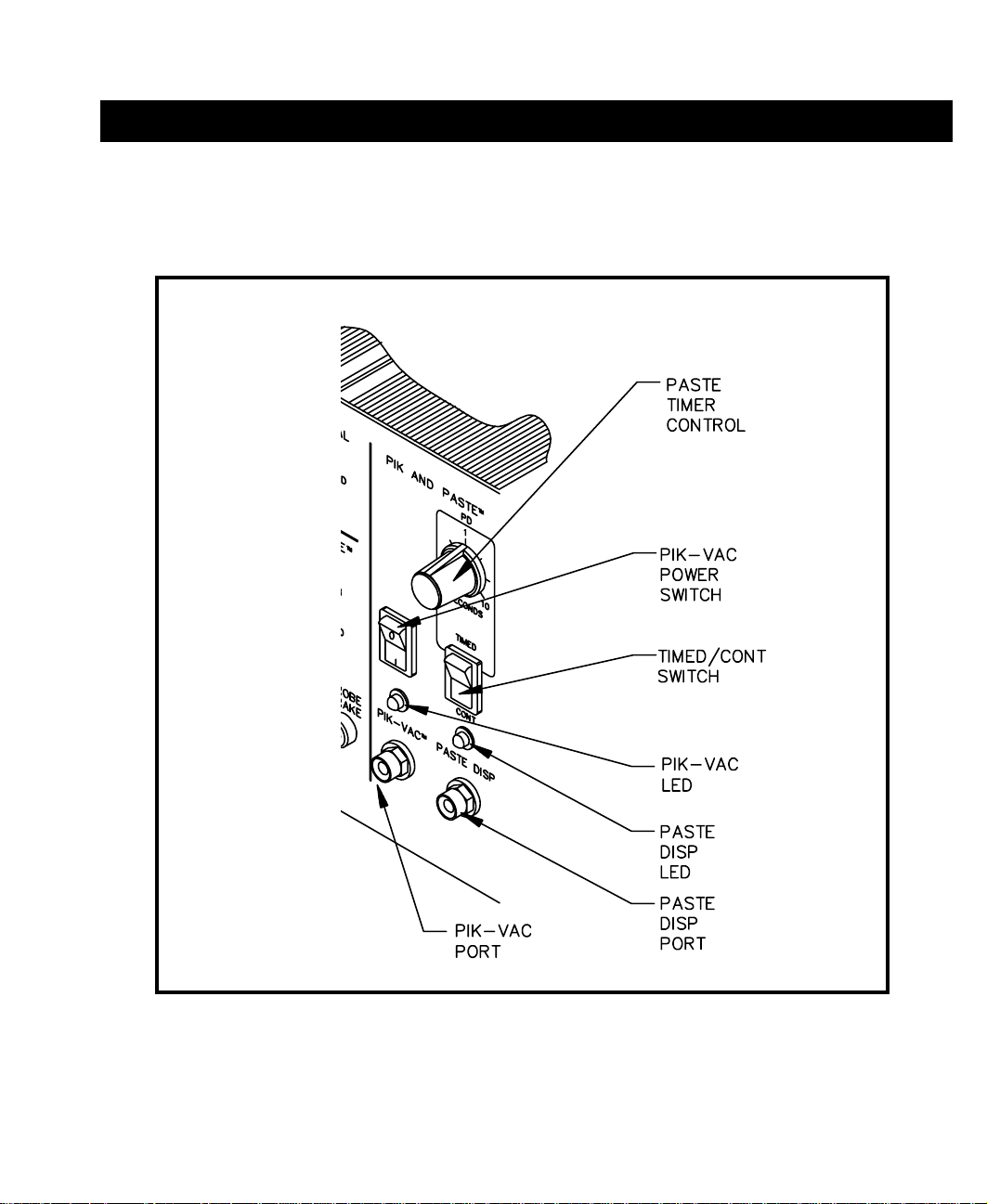
PIK AND PASTE
13. PIK-VAC POWER SWITCH - Turns power "ON" (1) or "OFF" (0). Controls power to the Pik-Vac
vacuum pump.
14. PIK-VAC LED - Illuminates Green to indicate Pik-Vac vacuum pump operation.
15. PIK-VAC PORT - Quick connect fitting which provides vacuum for Pik-Vac handpiece.
16. PIK AND PASTE TIMER CONTROL - Determines variable time controlled shot (0.1 - 10 seconds)
of Paste Dispense (PASTE DISP) air pressure upon foot pedal actuation (Foot Pedal Selector Switch
in PD position). Operates when TIMED/CONT Switch is in the TIMED position.
17. TIMED/CONT SWITCH - In CONT position, continuous air pressure is delivered from PASTE
DISP Port upon foot pedal actuation (Foot Pedal Selector Switch in PD position). In TIMED
position, measured interval of air pressure (0.1 - 10 seconds) is delivered from PASTE DISP Port
upon foot pedal actuation (Foot Pedal Selector Switch in PD position).
18. PASTE DISP LED - Illuminates Green when air pressure is delivered from the PASTE DISP Port.
Illuminates Yellow when the paste dispense pump reservoir is charging (no air pressure delivery from
P ASTE DISP Port).
19. PASTE DISP PORT - Quick connect fitting which provides air pressure (timed or continuous) to
dispensing barrel.
8
Page 14
GENERAL INFORMATION
Figure 5. Pik And Paste Section
9
Page 15

GENERAL INFORMATION
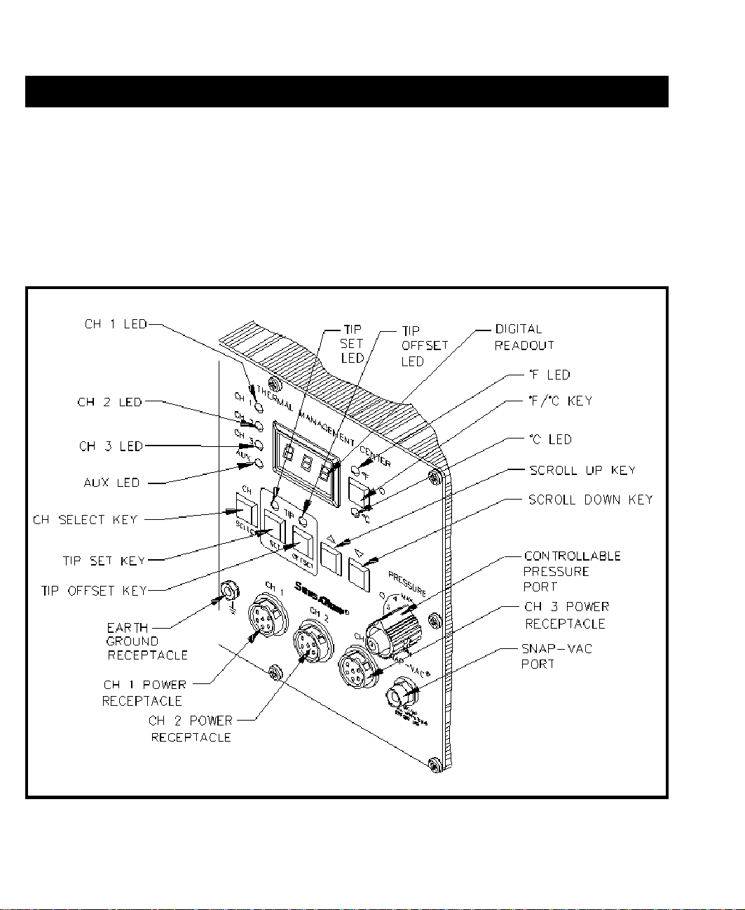
THERMAL MANAGEMENT CENTER
Refer to the illustration following for location of parts.
20. CH 1 POWER RECEPTACLE - Provides power, tip ground, sensing circuitry and finger switch
connection from PRC 2000 system to handpiece connected to Channel 1 (CH 1).
21. CH 2 POWER RECEPTACLE - Provides power, tip ground, sensing circuitry and finger switch
connection from PRC 2000 system to handpiece connected to Channel 2 (CH 2).
22. CH 3 POWER RECEPTACLE - Provides power, tip ground, sensing circuitry and finger switch
connection from PRC 2000 system to handpiece connected to Channel 3 (CH 3).
23. SNAP-VAC PORT - Quick connect fitting which provides quick-rise vacuum for Sodr-X-Tractor or
ThermoPik handpieces.
24. CONTROLLABLE PRESSURE PORT - Quick connect fitting with adjustable valve which
provides variable air flow for Mini ThermoJet handpiece and Sodr-X-Tractor handpiece (in Hot Jet
Mode).
25. DIGITAL READOUT - Provides a three digit display of the Current Channel (channel with
illuminated LED; CH 1, CH 2, CH 3 or AUX 1, AUX 2, AUX 3) temperature information. This
includes: Operating Tip Temperature in Temperature Display Mode (normal operation), Tip
Temperature Offset Constant in TIP OFFSET Mode, Set Tip Temperature in TIP SET Mode, and
other information in Calibration (CAL) Mode.
26. °F/°C KEY - Selects °F or °C display of Set and Operating Temperatures and Tip Temperature Offset
Constants.
27. °F LED - Illuminates when Set and Operating Tip Temperatures and Tip Temperature Offset Constants
are displayed in °F.
28. °C LED - Illuminates when Set and Operating Tip Temperatures and Tip Temperature Offset
Constants are displayed in °C.
29. CH 1 LED - Illuminates when Channel 1 (CH 1) or Auxiliary Channel (AUX 1) is the Current
Channel (i.e., the channel (with connected handpiece/tip or auxiliary accessory) whose temperature
information is displayed on the Digital Readout).
10
Page 16

GENERAL INFORMATION
30. CH 2 LED - Illuminates when Channel 2 (CH 2) or Auxiliary Channel (AUX 2) is the Current
Channel (i.e., the channel (with connected handpiece/tip or auxiliary accessory) whose temperature
information is displayed on the Digital Readout).
31. CH 3 LED - Illuminates when Channel 3 (CH 3) or Auxiliary Channel (AUX 3) is the Current
Channel (i.e., the channel (with connected handpiece/tip or auxiliary accessory) whose temperature
information is displayed on the Digital Readout).
32. AUX LED - Illuminates when an auxiliary channel (on system rear panel) is the Current Channel
(i.e., the channel (with connected handpiece/tip or auxiliary accessory) whose temperature information
is displayed on the Digital Readout). One of the CH 1, CH 2 or CH 3 LEDs will illuminate
simultaneously with the Auxiliary LED to indicate, respectively, which of the auxiliary channels is
active (AUX 1, AUX 2 or AUX 3).
33. CH SELECT KEY - Selects the Current Channel (among “Active Channels” i.e., those with a
connected handpiece or auxiliary accessory).
34. TIP SET KEY - Allows the operator to adjust the Set Tip Temperature for the handpiece/tip
combination or Set Temperature for the auxiliary accessory connected to the Current Channel. Places
the THERMAL MANAGEMENT CENTER in the TIP SET (Tip Temperature Set) Mode.
35. TIP SET LED - Flashes when TIP SET Key is pressed indicating that the THERMAL
MANAGEMENT CENTER is in TIP SET Mode.
36. TIP OFFSET KEY - Allows the operator to adjust the TIP OFFSET CONSTANT for the handpiece
or auxiliary accessory connected to the Current Channel. Places the THERMAL MANAGEMENT
CENTER in the TIP OFFSET (Tip Temperature Offset) Mode.
37. TIP OFFSET LED - Flashes when TIP OFFSET Key is pressed indicating that the THERMAL
MANAGEMENT CENTER is in the TIP OFFSET Mode. Remains illuminated (not flashing) in
Temperature Display Mode (normal operating mode) when a Tip Temperature Offset Constant of
greater than “3” for °C (“6” for °F) is entered.
38. SCROLL UP KEY - Increases the Set Tip Temperature (in TIP TEMPERATURE SET Mode) and Tip
Temperature Offset Constant (in TIP TEMPERATURE OFFSET Mode) in one, then ten degree
increments. Also used in “CAL” (Calibration) Mode.
11
Page 17
GENERAL INFORMATION
39. SCROLL DOWN KEY - Decreases the Set Tip Temperature (in TIP SET Mode) and Tip
Temperature Offset Constant (in TIP OFFSET Mode) in one, then ten degree increments. Also used
in “CAL” (Calibration) Mode.
40. EARTH GROUND RECEPTACLE - Provides positive earth ground to which a ground cable can be
connected from the workpiece or work surface as part of a static control program.
Figure 6. Thermal Management Center Parts I.D.
12
Page 18

GENERAL INFORMATION
13
Page 19

GENERAL INFORMATION
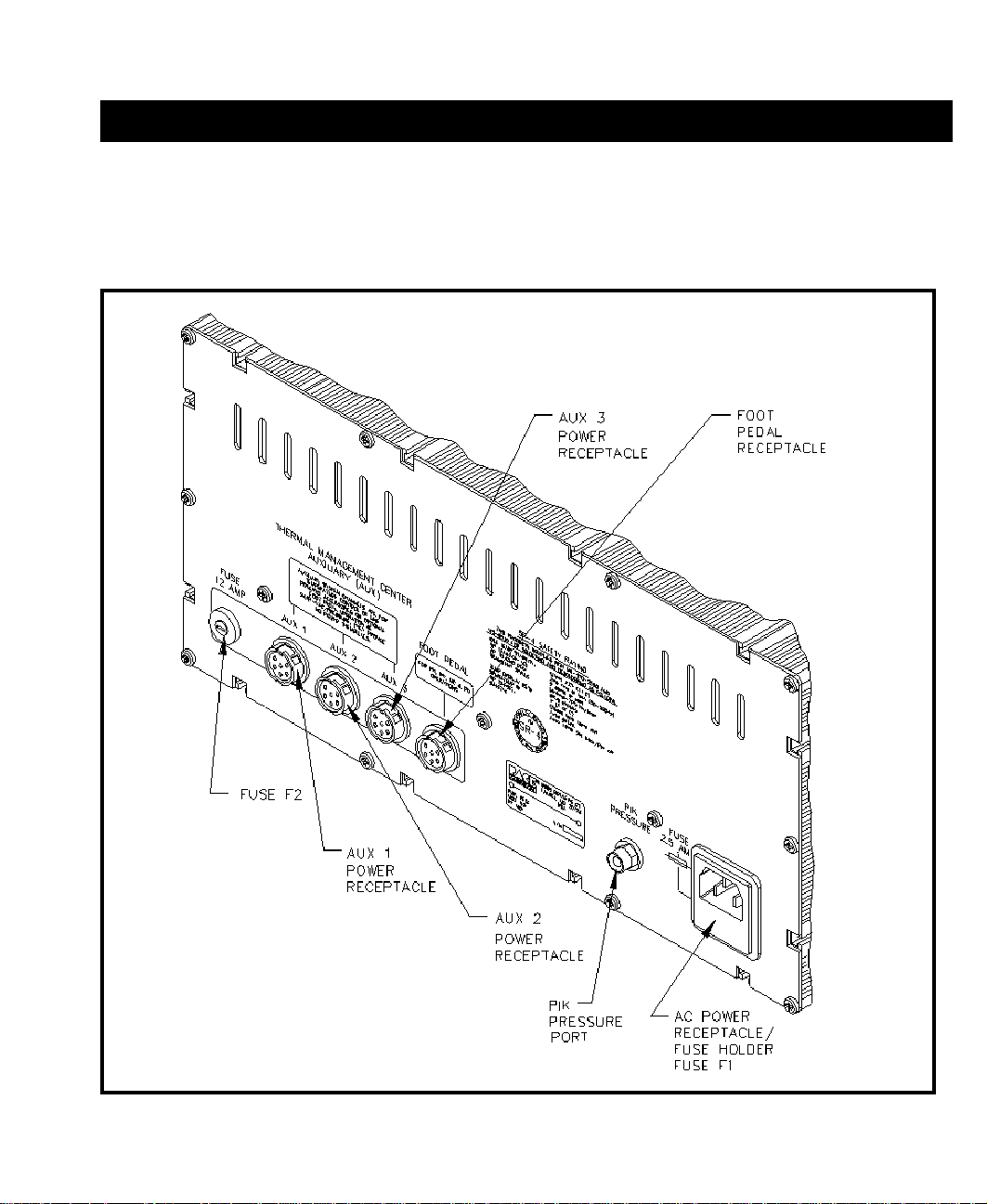
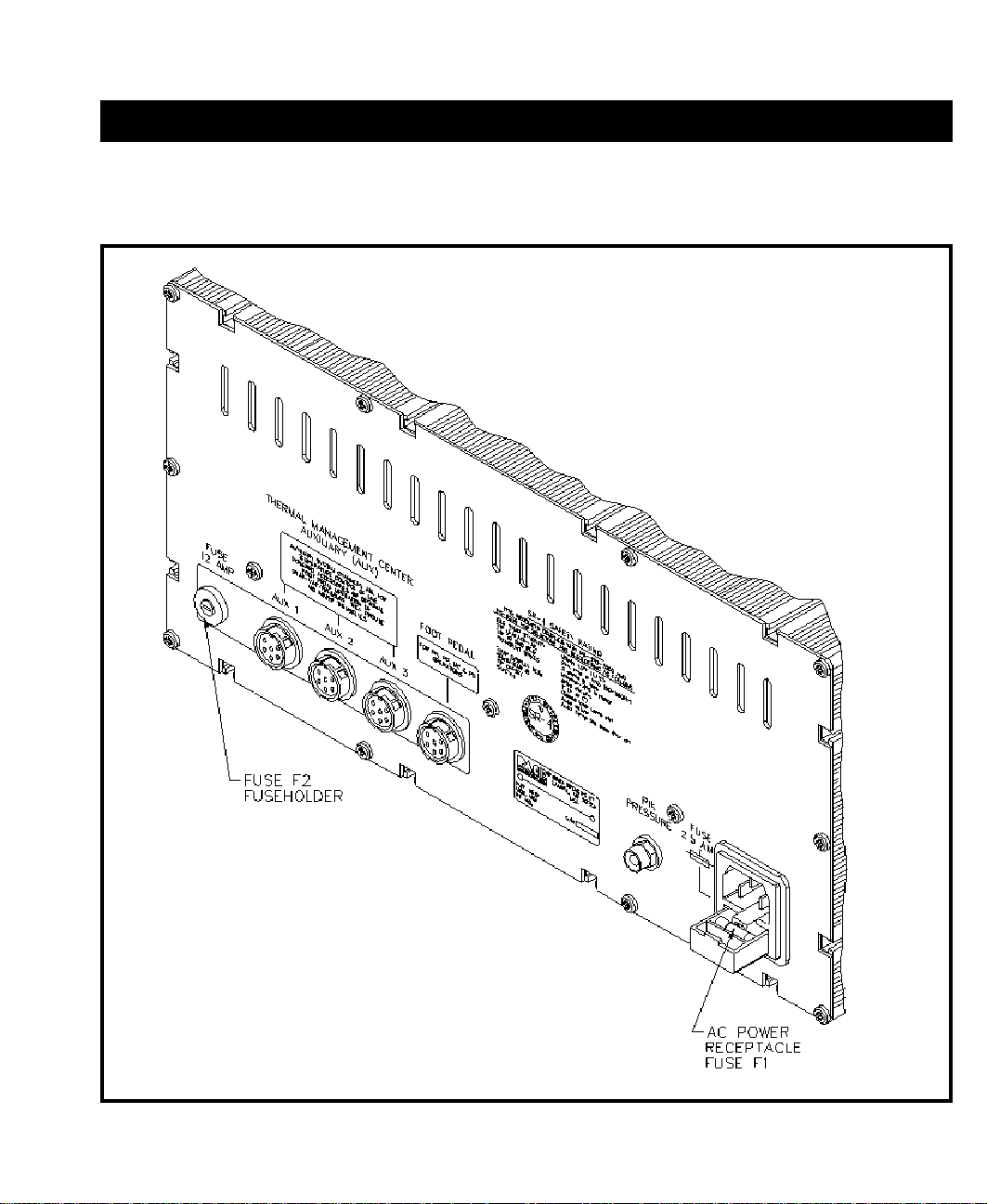
REAR PANEL
41. AC POWER RECEPTACLE/FUSE HOLDER - Receptacle for providing power to the PRC 2000
system from AC outlet through power cord. Also location of fuse (F1) which protects the system from
overcurrent conditions.
42. FUSE F1 - Provides overload protection for PRC 2000 system.
43. FOOT PEDAL RECEPTACLE - Input for foot pedal which operates the Pik and Paste, MicroChine,
Pulse Plate or Pulse Heat features of the system as determined by the FOOT PEDAL Selector Switch.
This receptacle is not connected to the Thermal Management Center controls.
NOTE
The Auxiliary Power Receptacles listed below (items 44-46) will provide
temperature control for line operated auxiliary accessories or foot pedal
operation only. SensaTemp handpieces will not function properly if
connected to these outputs.
44. AUX 1 POWER RECEPTACLE - Provides temperature control, tip ground sensing circuitry and
finger switch connection from THERMAL MANAGEMENT CENTER to the auxiliary accessory
connected to Auxiliary Channel 1. Foot pedal attachment to this receptacle will allow vacuum/
pressure pump operation through foot pedal actuation.
45. AUX 2 POWER RECEPTACLE - Provides temperature control, tip ground sensing circuitry and
finger switch connection from THERMAL MANAGEMENT CENTER to the auxiliary accessory
connected to Auxiliary Channel 2. Foot pedal attachment to this receptacle will allow vacuum/
pressure pump operation through foot pedal actuation.
46. AUX 3 POWER RECEPTACLE - Provides temperature control, tip ground sensing circuitry and
finger switch connection from THERMAL MANAGEMENT CENTER to the auxiliary accessory
connected to Auxiliary Channel 3. Foot pedal attachment to this receptacle will allow vacuum/
pressure pump operation through foot pedal actuation.
47. FUSE F2 - Provides overload protection for CH 1, CH 2 and CH 3 power receptacles.
48. PIK PRESSURE PORT - Low pressure output with quick connect fitting. Controlled by PIK-VAC
Power Switch (front panel).
14
Page 20
GENERAL INFORMATION
Figure 7. Rear Panel Parts I.D.
15
Page 21

SAFETY
The purpose of this "SAFETY" section is to inform users of the heading guidelines used in this manual to indicate
special Notes, Cautions, Warnings or Dangers. Also included are recommended precautions which must be
observed when operating or servicing this product.
HEADING GUIDELINES
PACE adheres to the following Heading Guidelines (based on OSHA guidelines) when listing special information
or precautions to be taken. Especially important are all procedures and practices which, if not strictly observed,
could result in injury or loss of life.
These "NOTES", "CAUTIONS","WARNINGS" and "DANGERS" are inserted in this manual whenever deemed
necessary. They appear in a blocked off form with double outline and a shaded background to highlight the
information as shown below.
NOTE
XXXXXXXXXXXXXXXXXXXXXXXXXXXXXXXXXXXXXXXXXXXXXXXXXX
NOTE
Used to indicate a statement of company recommendation or policy. The message may relate directly or
indirectly to the safety of personnel or protection of property. NOTE is not associated directly with a hazard or
hazardous situation and is not used in place of "CAUTION", "WARNING" or "DANGER".
CAUTION
Used to indicate a hazardous situation which may result in minor or moderate injury. May also be used to alert
personnel to conditions, procedures and practices which, if not observed, could result in damage to or destruction
of the product or other equipment.
WARNING
Used to define additional information that if not closely followed might result in serious damage to equipment
and represent a potential for serious personnel injury.
DANGER
Defines additional information that if not closely followed might result in severe personnel injury or death.
Danger is not used for property damage unless personnel injury risk is present.
16
Page 22

SAFETY
PRECAUTIONS
The following are general safety precautions which personnel must understand and follow when using or
servicing this product. These precautions may or may not be included elsewhere in this manual.
USEAGE PRECAUTIONS
CAUTIONS
1. SensaTemp handpiece heaters and installed tips are hot when handpiece is powered on. DO NOT
touch either the heater or tip. Severe burns may result! Always store handpiece in the appropriate
cubby when not in use.
2. Always use this system in a well ventilated area. A fume extraction system such as those available
from PACE are highly recommended to protect personnel from solder flux fumes.
3. Exercise proper precautions when using materials (e.g., fluxes & solder paste). Refer to the Material
Safety Data Sheet (MSDS) supplied with each chemical and adhere to all safety precautions
recommended by the manufacturer.
4. The use of Safety Glasses is recommended when plating or machining.
NOTES
1. The solder collection chamber in the PACE Sodr-X-Tractor is made of glass. Never remove this
chamber using pliers. Breakage of the chamber may result. Always remove using the procedures
recommended by PACE in the associated handpiece manual.
2. The glass solder collection chamber in the PACE Sodr-X-Tractor is hot when the handpiece is in use.
When removing the chamber for cleaning, never touch the glass with bare hands. Allow the chamber
to cool before cleaning.
3. Disconnect the MicroChine handpiece from the power source or turn the power switch off before
installing or changing tools.
17
Page 23

SAFETY
SERVICING PRECAUTIONS
DANGERS
POTENTIAL SHOCK HAZARD - Repair procedures performed on this product should be
performed by qualified service personnel only. Line voltage parts will be exposed when equipment is
disassembled. Service personnel must avoid contact with these parts when troubleshooting the power
source.
NOTES
To insure continued peak performance, use genuine PACE replacement parts.
18
Page 24

REPAIR
REPAIR PROCEDURE
The "REPAIR" section of this manual provides the technician with the information necessary to determine the
source of a malfunction and take the necessary steps to correct it. In order to perform the most expedient
repair, the technician must follow the process listed below step by step, in order. Failure to do so will make
the diagnosis and repair much more difficult.
1. PERIODIC MAINTENANCE - No periodic or special maintenance is required on this system.
2. SERVICE HINTS - Read these helpful hints which give information on operation and
troubleshooting.
3. CORRECTIVE MAINTENANCE - A guide for resolving malfunctions caused by improper
maintenance or handpiece failure. Locate the "Symptom" in the "Corrective Maintenance" section
which best describes the malfunction of the failed unit. Check each point described under "Solution"
in order of listing.
4. CALIBRATION - Lists procedures for performing tip temperature tests to check handpieces.
Perform these procedures periodically or if operating tip temperatures appear to be incorrect.
5. DISASSEMBLY/ASSEMBLY - Contains Disassembly/Assembly instructions which enables the
technician to disassemble and assemble the unit properly.
6. FLOW CHARTS, SCHEMATICS - Easy to follow Flow Charts, Assembly Drawings, Schematics and
Wiring Diagrams which enable the technician to determine the source of a malfunction down to an
assembly (e.g., Main PCB Assembly) level. Locate the Flow Chart which best describes the
malfunction of the failed unit. Follow the instructions on the Flow Chart and perform the checks
indicated to determine the source of the malfunction. The schematics shown are for systems
produced at the time of publication of this manual. If any variances in components or wiring are
detected on your system contact PACE Customer Service for assistance (see step #7 below).
7. PACE CUSTOMER SERVICE - If the cause for the malfunction has not been determined at this
point, call PACE Customer Service at TEL:(301) 490-9860, FAX (301) 604-9215.
WARNING
POTENTIAL SHOCK HAZARD Repair Procedures are to be per-
formed by qualified service personnel only. Removal of the power
source panels exposes line voltage parts. Service personnel must
insure that the AC Power Cord is disconnected prior to disassembly.
19
Page 25

REPAIR
SERVICE HINTS
1. OPERATIONAL PROBLEMS: Refer to the PACE Operation & Maintenance Manual (P/N 5050-
0313) for complete operational instructions on use of this product. If a Password has been installed by
the system user, remove the Password before proceeding with the repair. The user can reinstall the
Password after the system is repaired.
2. VACUUM FAILURES: Failures of this nature can be caused by either the unit or the SensaTemp
handpiece. Remove the Air Hose (and attached VisiFilter) from the SNAP-VAC Port and check for
vacuum at the port. If sufficient vacuum is present, the malfunction exists in the handpiece. Further,
if vacuum is sufficient at the port, check the vacuum level at the end of the glass solder collection
chamber (Sodr-X-Tractor handpieces only, chamber must be checked cold). Take the applicable steps
shown following.
a) Handpiece Failures: Replace VisiFilter if necessary; clean heater bore and replace tip, check air
hose for holes and ensure that glass solder collection chamber (Sodr-X-Tractor handpieces only) is
properly seated against heater seal.
b) Unit Failures: Remove the unit front panel (see "Disassembly/Assembly"). Check internal hosing
for kinks and replace internal VisiFilter (attached to pressure port on motor pump assembly).
3. HEATING CONTROL CIRCUITS: Must be checked under load (with handpiece/s plugged in). The
output(s) are obtained by switching triacs on and off. The voltage level to the handpiece(s) does not
change when adjusting the Set Tip Temperature. The control circuit of the unit varies the duty cycle of
voltage application as required to achieve and maintain the set temperature of the handpiece.
4. HEATING FAILURES: Usually caused by defective SensaTemp handpiece heaters. Refer to the
"Heater Assembly Checkout Procedures", Table I. When checking the system power source, use a
known good handpiece.
20
Page 26
REPAIR
CORRECTIVE MAINTENANCE
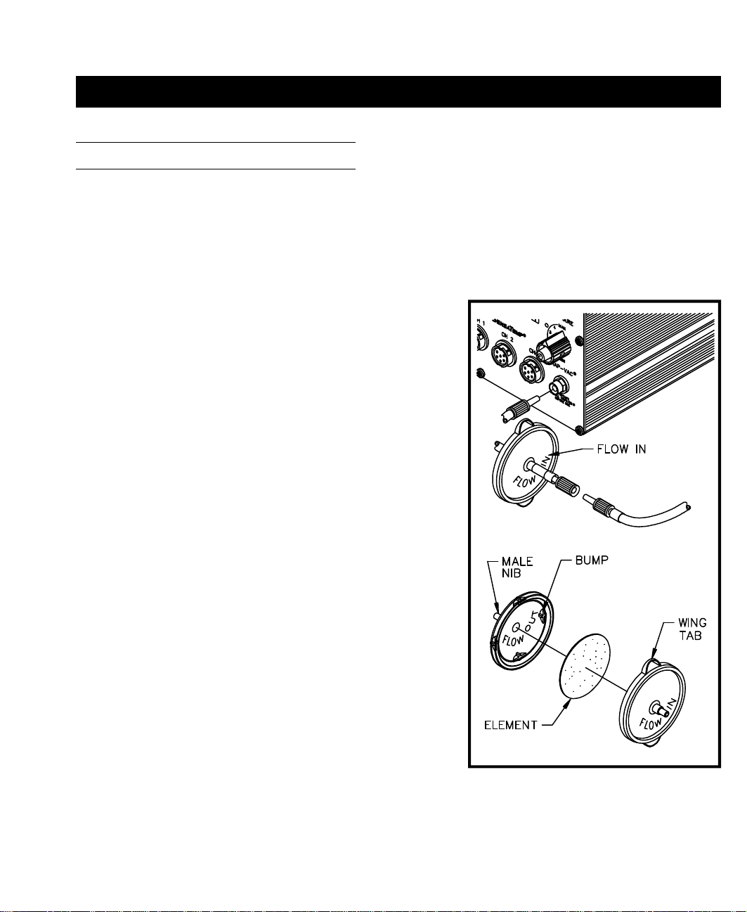
VISIFILTER ELEMENT REPLACEMENT
Follow the procedure listed below to replace the VisiFilter element when it becomes clogged or discolored.
1. Disconnect the handpiece air hose by gently turning and
pulling the coupled Fittings.
2. Disconnect the Visifilter and hose assembly from the
Power Source by gently turning and pulling the male
Fitting inserted into the SNAP-VAC Port.
3. Disconnect VisiFilter from both attached 1 inch air hoses
by gently turning and pulling the VisiFilter while holding
each of the hoses.
4. Separate the 2 plastic housing halves of the VisiFilter in the
following manner.
a) Grasp the VisiFilter in the palm of the hand with the
Male Nib (air hose connection) marked "FLOW IN"
facing you.
b) Pull against one of the Wing Tabs while pulling on the
Male Nib with the free hand to open the
interconnection of the plastic housings at that Wing
Tab.
c) Pull against the second Wing Tab while pulling on the
Male Nib to open the remaining interconnection and
separate the plastic housings.
5. Remove the old or discolored Element and discard.
6. Insert the replacement VisiFilter Element into the housing
marked "FLOW IN". Center the Element in the housing
well.
7. Squeeze the 2 plastic housing halves together using 4 plastic
Bumps on the housing marked "FLOW OUT" as pressure
points. The 2 plastic housings will snap together and lock the
VisiFilter Element in position.
8. Reconnect the 1 inch air hoses (removed in step 3) to the
VisiFilter.
9. Attach VisiFilter and hose assembly to Power Source by
inserting male Fitting into the SNAP-VAC Port.
Figure 8. VisiFilter Element Replacement
21
Page 27

REPAIR
SENSATEMP HANDPIECES
The following "Heater Assembly Checkout Procedures" are applicable to all PACE SensaTemp handpieces
except for the TT-65 ThermoTweez handpiece. Refer to either of the TT-65 manuals (P/N 5050-0300 or
5050-0336) for troubleshooting procedures pertinent to that handpiece.
Perform the "Heater Assembly Checkout Procedures" shown below with the handpiece (and heater) at room
temperature. If the handpiece is warm, resistance readings will be different from those shown.
SYMPTOM CHECKOUT PROCEDURE CAUSE SOLUTION
No heat Check resistance - Pin 2 to Pin 5.
Refer to handpiece manual for
resistance tolerances.
Handpiece
overheating
Fuse blows
when unit is
turned on.
No Ground
on Tip.
If resistance is high - Open Heater
Check resistance - Pin 3 to Pin 6.
If circuit reads open -
Check resistance - Pin 3 to Pin 6.
Resistance should be 110 ohms.
If circuit reads less than 105 ohms
Check resistance - Pin 2 to Pin 5.
Refer to handpiece manual for
resistance tolerances.
If resistance is low -
Check resistance - Pin 4 to a
NEW Tip. Resistance should be
less than 2 ohms.
If not -
Open Sensor
Shorted Sensor
Solder short in
Handpiece.
Shorted Heater Replace Heater
Oxidation buildup
in Heater Bore.
Defective Heater Replace Heater
Replace Heater
Assembly.
Replace Heater
Assembly.
Replace Heater
Assembly.
Remove Short.
Replace Heater
Assembly & Fuse F1.
Assembly & Fuse F1.
Clean Heater Bore
using appropriate
wire brush.
HEATER
SPECIFICATIONS
SX-70 = 8 - 10
ohms
SP-2A = 8 - 10
ohms
SP-1A = 10 - 12
ohms
TP-65 = 9 - 11
ohms
TJ-70 = 6 - 8 ohms
Table I. Heater Assembly Checkout Procedures
22
Page 28
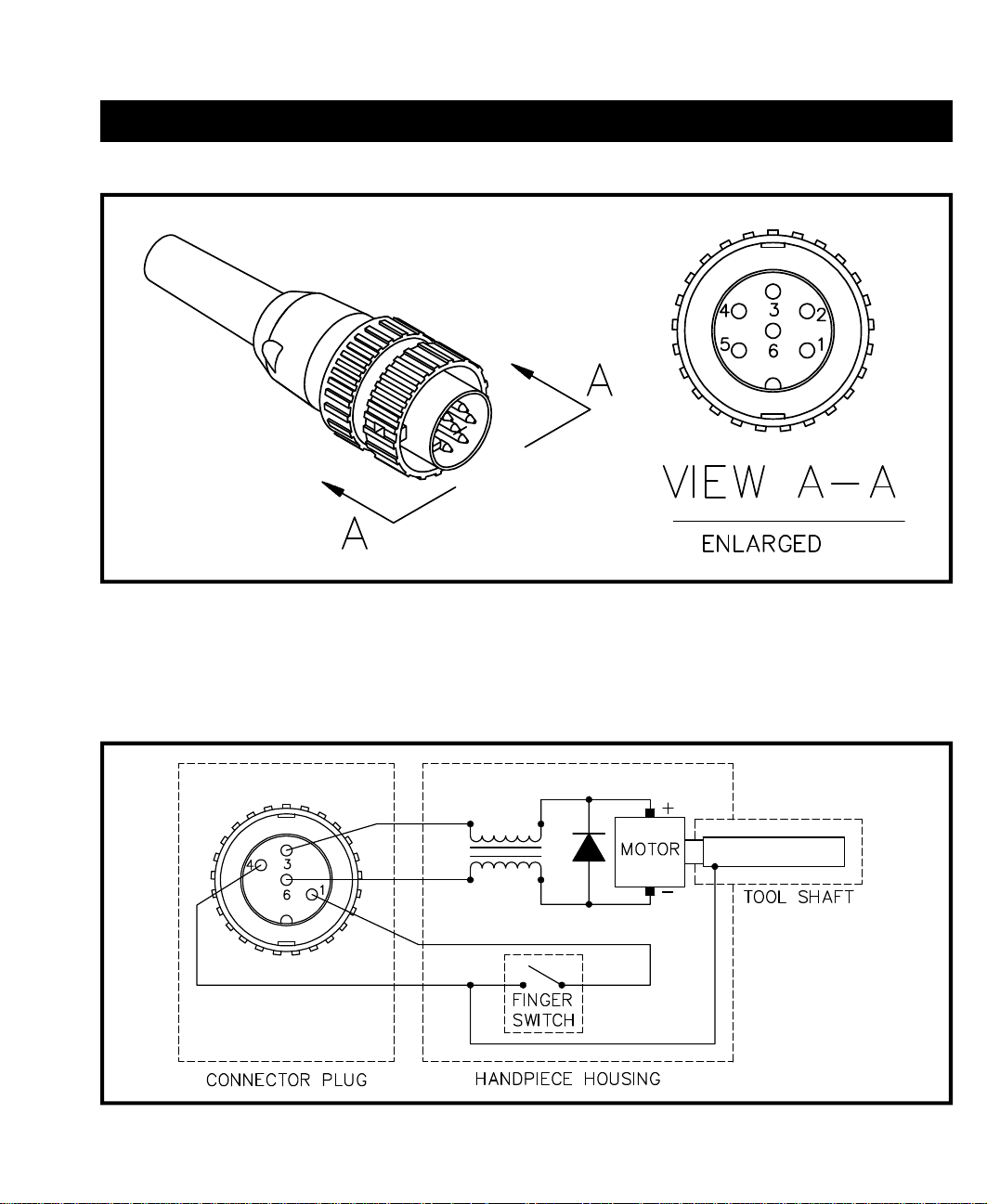
Figure 9. Connector Plug Wiring
REPAIR
MICROCHINE HANDPIECE
Figure 10. MicroChine Wiring
23
Page 29

REPAIR
MICROCHINE HANDPIECE CONT'D
SYMPTOM CHECKOUT PROCEDURE CAUSE SOLUTIO
Motor will not run.
Status LED
illuminated Red
in color.
Motor will not run.
Status LED not
illuminated Red
in color.
Motor runs
continuously.
No Ground
on tip of installed
Tool.
Unplug all SensaTemp
handpieces. If motor now runs
and Status LED turns off -
Check resistance - Pin 1 to Pin 4
with Finger Switch depressed.
If resistance is greater than 1
ohm -
Check resistance - Pin 3 to Pin
6. Resistance should be 3 to 40
ohms. If not -
Check resistance - Pin 1 to Pin
4. Resistance should read
open circuit. If not -
Check resistance - Pin 4 to a
NEW Tip. Resistance should
be less than 2 ohms.
If not -
Shorted
SensaTemp
handpiece.
Open Switch
circuit.
Defective
Motor circuit.
Shorted Finger
Switch.
Oxidation in
drill collet.
Open ground
circuit.
Repair
shorted
SensaTem
handpiece.
Replace
MicroChine
Handpiece.
Replace
MicroChine
Handpiece.
Replace
MicroChine
Handpiece.
Clean
MicroChine
Collet.
Replace
MicroChine
Handpiece.
Table II. MicroChine Handpiece Checkout Procedures
24
Page 30

REPAIR
POWER SOURCE
Contact PACE Customer Service at Tel. (301) 490-9860, FAX (301) 604-9215 to obtain any replacement parts.
Refer to the "Replacement Parts" section of this manual for part numbers.
SYMPTOM PROBABLE CAUSE SOLUTION
Digital Readout is blank.
No functions on system.
E-1 displayed on Digital
Readout.
E-2, E-3 or E-4 displayed
on Digital Readout.
No heat on SensaTemp
handpiece(s) at Thermal
Management Center.
Digital Readout displays
very low temperature.
Blown Fuse (F1) Replace Fuse F1 located on rear of
Power Source in the AC Receptacle.
All Channels are unplugged
on Thermal Mgmt. Center.
Open sensor in SensaTemp
handpiece.
Defective heater assembly in
SensaTemp handpiece.
Open heater. Refer to handpiece Operation Manual.
Blown 12 Amp Fuse. Replace 12 amp Fuse located on rear of
Handpieces connected to
AUX receptacles.
SensaTemp handpieces are
not AUX compatible.
Damaged Power Receptacle. Replace Power Receptacle.
Plug SensaTemp handpiece into CH 1,
CH 2 OR CH 3.
Refer to handpiece Operation Manual for
Corrective Maintenance procedures.
Unplug all SensaTemp handpieces.
Plug handpieces back in one at a time.
When defective handpiece is
connected, "E" code will be displayed.
Refer to handpiece Operation Manual.
Power Source.Disconnect all
SensaTemp handpieces before
powering system up. Plug SensaTemp
handpieces back in one at a time. If the
fuse blows when a handpiece is plugged
in, the handpiece is shorted. Repair the
handpiece.
Disconnect incompatible handpieces
from AUX Receptacles. Connect to
Power Receptacles on front panel.
System overload. Check for
defective SensaTemp
handpiece.
Microprocessor pcb defect. Replace Microprocessor pcb.
Table III. Corrective Maintenance, Power Source
Disconnect defective handpiece.
220 Volt version only: Overtemp cutout
in transformer may open. Allow
transformer to cool.
25
Page 31

REPAIR
POWER SOURCE CONT'D
Contact PACE Customer Service at Tel. (301) 490-9860, FAX (301) 604-9215 to obtain any replacement parts.
Refer to the "Replacement Parts" section of this manual for part numbers.
SYMPTOM PROBABLE CAUSE SOLUTION
Foot Pedal does not activate
vacuum or air pressure for
Thermal Management Center.
Keys on Thermal Management
Center don't function properly.
Cannot adjust Offset or Set Tip
Temperature on Thermal
Management Center. Digital
Readout displays "P--".
Digital Readout on Thermal
Management Center is
inaccurate when using a
known good handpiece.
Foot Pedal connected to
incorrect receptacle for
Thermal Mgt. Center motor
pump activation.
Defective Foot Pedal. Check switch closure at Foot Pedal
Defective Motor Pump. Replace Motor Pump.
Microprocessor pcb defect. Replace Microprocessor pcb.
Key caps binding. Clean and/or adjust Key caps.
Display pcb misaligned or
defective.
Microprocessor pcb defect. Replace Microprocessor pcb.
System is requesting
Password entry.
Operator forgot Password. Clear Password. See "Clearing a
System out of calibration. Wait 4 minutes for system to perform
Microprocessor pcb defect. Replace Microprocessor pcb.
Connect Foot Pedal to any spare AUX
Power Receptacle on Thermal
Management Center.
connector plug. Repair Foot Pedal if
defective.
Replace Display pcb.
Enter Password.
Password" instructions.
automatic internal recalibration.
Table III. Corrective Maintenance, Power Source Cont'd
26
Page 32

REPAIR
Contact PACE Customer Service at Tel. (301) 490-9860, FAX (301) 604-9215 to obtain any replacement parts.
Refer to the "Replacement Parts" section of this manual for part numbers.
SYMPTOM PROBABLE CAUSE SOLUTION
Insufficient SNAP-VAC
(vacuum) or air pressure.
Excessive motor pump noise.
Digital Readout display is erratic. Shorted handpiece or
Paste dispenser pressure is
insufficient or nonexistent.
Excessive noise during paste
dispense operation.
Table III. Corrective Maintenance, Power Source Cont'd
Air hose(s) and/or filter(s)
clogged.
Defective motor pump. Replace motor pump.
Microprocessor pcb defect. Replace Microprocessor pcb.
accessory.
Low AC line voltage. Check line voltage.
Display pcb defect. Replace Display pcb.
Microprocessor pcb defect. Replace Microprocessor pcb.
Poor air hose connections. Check air hose connections outside and
Clogged air filter. Replace filter.
Defective pump, valve or
reservoir.
Defective dispense pump. Replace dispense pump.
Multifunction pcb defect. Replace Multifunction pcb.
Replace any clogged filters and clear all
air hoses.
Disconnect handpieces and accessories
one at a time until Digital Readout
display is normal.
inside of system power source.
Replace defective part.
27
Page 33

REPAIR
POWER SOURCE CONT'D
Contact PACE Customer Service at Tel. (301) 490-9860, FAX (301) 604-9215 to obtain any replacement parts.
Refer to the "Replacement Parts" section of this manual for part numbers.
SYMPTOM PROBABLE CAUSE SOLUTION
MicroChine Status LED
continuously illuminated
Red in color.
MicroChine Probe Brake
activates prematurely.
MicroChine continues to run
after release of finger switch or
foot pedal.
MicroChine Probe Brake
reacts sluggishly or is
inoperable.
Shorted SensaTemp
handpiece or accessory on
Thermal Management Center.
Multifunction pcb defect. Replace Multifunction pcb.
Probe Brake test lead is
connected to or exciting a
circuit having less than 500
ohms resistance to ground.
Defective MicroChine
handpiece.
Probe Brake test lead is
connected to inappropriate
conductor on workpiece.
Bit in MicroChine is not
conductive (non metallic).
Defective MicroChine
handpiece.
Multifunction pcb defective. Replace Multifunction pcb.
Turn system power OFF for 1 minu te.
Disconnect handpieces and
accessories. Turn system power ON
and run MicroChine. LED will turn off if
the problem is caused by a handpiece or
accessory. Repair handpiece or
accessory.
Remove ground lead from pcb.
Refer to Table II to check MicroChine
handpiece. Replace MicroChine
handpiece if defective.
Connect Probe Brake test lead to proper
conductor.
Install conductive bit.
Replace handpiece.
MicroChine will not operate.
Probe Brake LED is illuminated
Green in color.
Damaged Power Receptacle. Replace Power Receptacle.
Defective MicroChine
handpiece.
Multifunction pcb defective. Replace Multifunction pcb.
Table III. Corrective Maintenance, Power Source Cont'd
28
Replace handpiece.
Page 34

REPAIR
Contact PACE Customer Service at Tel. (301) 490-9860, FAX (301) 604-9215 to obtain any replacement parts.
Refer to the "Replacement Parts" section of this manual for part numbers.
SYMPTOM PROBABLE CAUSE SOLUTION
MicroChine speed is grossly
inaccurate.
Pik-Vac has insufficient
vacuum.
Pulse Heat handpieces do not
heat. Pulse Heat LED is
illuminated Green in color.
Foot Pedal does not operate
in PH, PP, MP or
PD position.
MicroChine is overloaded.
Status LED is illuminated
Yellow in color.
Defective handpiece. Replace handpiece.
Multifunction pcb defect. Replace Multifunction pcb.
"Low Pressure" output on
power source rear panel is
obstructed.
Defective Pik-Vac pump
assembly.
Loose connection at Pulse
Heat Outputs or handpiece
connector.
Defective Universal Power
Cord.
Multifunction pcb defect. Replace Multifunction pcb.
Foot pedal connected to
incorrect receptacle.
Defective foot pedal switch. Check for switch closure at foot pedal
Multifunction pcb defect. Replace Multifunction pcb.
Disengage MicroChine from workpiece.
Resume operation exerting less pressure
on handpiece.
Remove obstruction.
Replace Pik-Vac pump.
Tighten connections.
Check voltage at Pulse Heat Outputs.
Replace Universal Power Cord if
defective.
Connect foot pedal to receptacle on rear
panel of power source marked "FOOT
PEDAL".
connector plug pins. Repair foot pedal if
defective.
Table III. Corrective Maintenance, Power Source Cont'd
29
Page 35

REPAIR
CALIBRATION
All PACE SensaTemp controllers can be checked for calibration without the need to adjust any internal controls.
If there is a requirement to check the actual tip temperature of a SensaTemp handpiece, perform the following
procedure for attaching a thermocouple wire to the handpiece tip. A Process Monitor is available from PACE
which will provide a temperature readout and can perform a variety of additional tests such as Tip to Ground
resistance and vacuum checks.
A thermocouple may be attached to a tip by spot welding a thermocouple wire onto the end of the tip or by
embedding the wire into a drilled hole at the tip end. Either method will produce accurate results. Tips (for
PACE equipment) with embedded K type thermocouples are available from PACE.
Pulse Heat handpieces are not closed loop temperature controlled and require no calibration.
MATERIALS REQUIRED
1. PACE Process Monitor or Temperature Meter.
2. Soldering Iron Tip. Listed below are the available tips PACE uses (with and without embedded
thermocouples).
a) Use PACE part number 7021-0004-P1 tip with embedded thermocouple or tip only part
number 1121-0337 on handpieces with 4.76 mm (3/16 inch) heater bore.
b) Use PACE part number 7021-0003-P1 tip with embedded thermocouple or tip only part
number 1121-0130 on handpieces with 3.18 mm (1/8 inch) heater bore.
NOTE
When using tips with embedded K type thermocouples supplied by PACE
with a K type Temperature Meter, a PACE part number 1332-0164-P1
RCA to Omega-style, K-type, thermocouple adapter must be used.
The following items are needed if you are NOT using the PACE part number 7021-0003-P1 or 7021-0004-P1
embedded tips.
3. Thermocouple, 30 AWG ("K" type when using Process Monitor or type compatible with Temperature
Meter).
4. Copper Wedge (used when embedding thermocouple) or 16 AWG Bare Copper Wire (1.22 mm
(.048 inch) O.D.).
5. Drill Bit (used when embedding thermocouple), 1.5 mm (.059 inch) diameter.
SPOTWELDING PROCEDURE
1. Place the thermocouple end onto the tip just past the tinned end (approximately 6.35 mm (.25 inch)).
2. Spotweld the thermocouple to the tip. Check to insure that the thermocouple is properly attached to
the tip.
30
Page 36
REPAIR
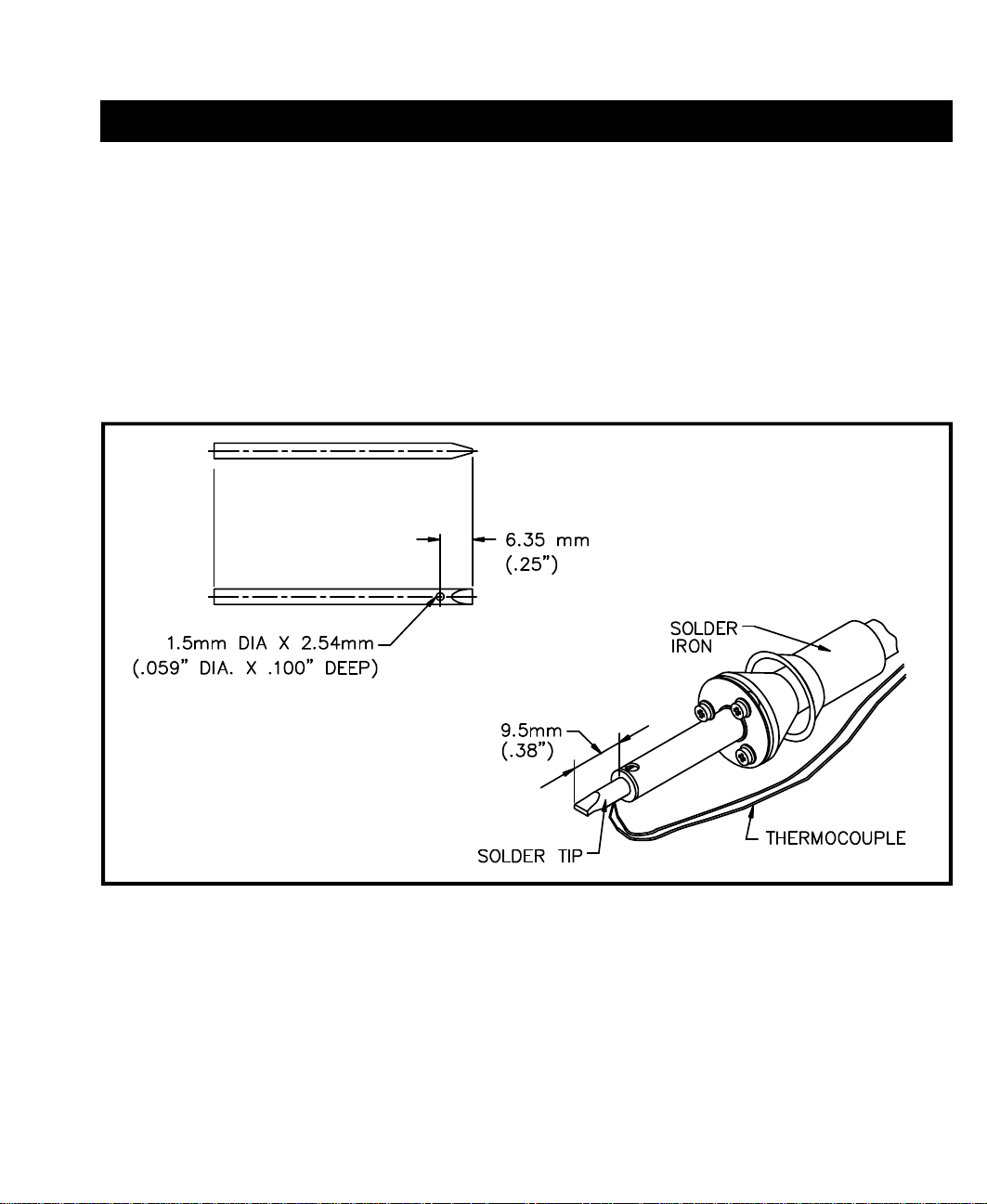
EMBEDDING PROCEDURE
1. Drill a 1.5 mm (.059 inch) hole just past the tinned end of the soldering tip (approximately 6.35 mm
(.25 inch) when using one of the recommended PACE tips). Drill to a depth of 2.54 mm (.100 inch).
2. Place the end of the thermocouple wire into the hole. Ensure that the end of the wire bottoms out in
the hole.
3. Wedge the thermocouple into place using the copper wedge or bare copper wire. The thermocouple
should be wedged as air tight as possible.
Figure 11. Thermocouple Attachment
TIP TEMPERATURE TEST
1. Install the tip into the handpiece to be tested with the end of the tip properly seated. The
recommended PACE tips are shown extending out of the heater 9.5mm (3/8 inch).
2. Connect the free end of the thermocouple wire to the PACE Process Monitor (or temperature meter).
3. Apply power to the handpiece and allow temperature to stabilize.
31
Page 37

REPAIR
DISASSEMBLY/ASSEMBLY
DISASSEMBLY
To disassemble the unit for servicing, perform the following procedure step by step, in sequence using the
illustrations as a guide. The procedure directs the technician to remove the power source from the chassis.
WARNING
POTENTIAL SHOCK HAZARD The following procedures are to be
performed by qualified service personnel only. Removal of the Power
Source panels exposes line voltage parts. Service personnel must insure
that the AC Power Cord is disconnected prior to disassembly.
1. Place the unit on a suitable work surface. Insure that the Power Cord has been disconnected from the
back of the power source.
32
Page 38
REPAIR
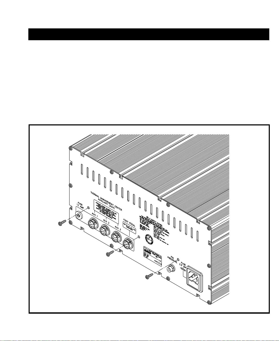
2. Position the PRC 2000 power source with the rear panel facing forward.
3. Remove the 3 rear panel mounting screws indicated on the rear panel. DO NOT remove any other
rear panel mounting screws.
Figure 12. Removing Rear Panel Screws
33
Page 39

REPAIR
DISASSEMBLY CONT'D
4. Reposition the unit with the Front Panel of the Power Source facing forward.
5. Remove the 10 Front Panel Mounting Screws.
6. Pull the Front Panel forward 2 inches to expose the interior of the Power Source. DO NOT disconnect
any electrical or air hose connections.
Figure 13. Removing Front Panel
34
Page 40

REPAIR
7. Locate the 4 Bolt Assemblies across the front, inside, bottom edge of the Power Source case.
8. Loosen each of the Hex Nuts on the 4 Bolt Assemblies.
9. Slide each of the Bolt Assemblies forward and remove the assemblies from the Power Source.
Figure 14. Removing Bolt Assemblies
35
Page 41

REPAIR
DISASSEMBLY CONT'D
10. Remove the power source from the case by grasping 2 of the metal posts which connect the pc boards
to the power source chassis. Pull the power source forward and out of the case.
11. Set the case aside.
12. The unit can now be connected to the house AC supply to troubleshoot the system.
Figure 15. Removing Power Source From Case
36
Page 42

ASSEMBLY
1. Disconnect the AC power cord.
WARNING
POTENTIAL SHOCK HAZARD Insure that the AC power is
disconnected before proceeding to step 2.
2. Place the case directly behind the power source. Insure that the power source is facing forward.
3. Slide the power source back into the case.
REPAIR
4. Reposition the power source with the rear panel facing forward. Reinstall the 3 rear panel mounting
screws.
5. Reposition the power source with the front panel facing forward. Reinstall the 4 bolt assemblies.
Tighten the hex nuts on each bolt assembly to secure the power source in position.
6. Insure that all air hoses are properly connected to the front panel. Refer to the "Air Hose Routing"
illustration.
7. Install the 10 front panel mounting screws to secure the panel to the case.
8. Check the power source for proper operation.
37
Page 43

REPAIR
38
Page 44

REPAIR
FLOW CHARTS
The following flow charts should be used to determine the source of a malfunction down to an assembly level.
Locate the flow chart which best describes the malfunction. If you are unsure about which flow chart to use,
begin with the "Power" flow chart which will direct you to the area of concern.
Insure that the power source has been removed from its case before performing the applicable procedure.
WARNING
POTENTIAL SHOCK HAZARD The follo wing Flow Chart procedures
are to be performed by qualified service personnel only. Line voltage
parts are exposed. Service personnel must avoid contact with these
parts when troubleshooting the power source.
39
Page 45
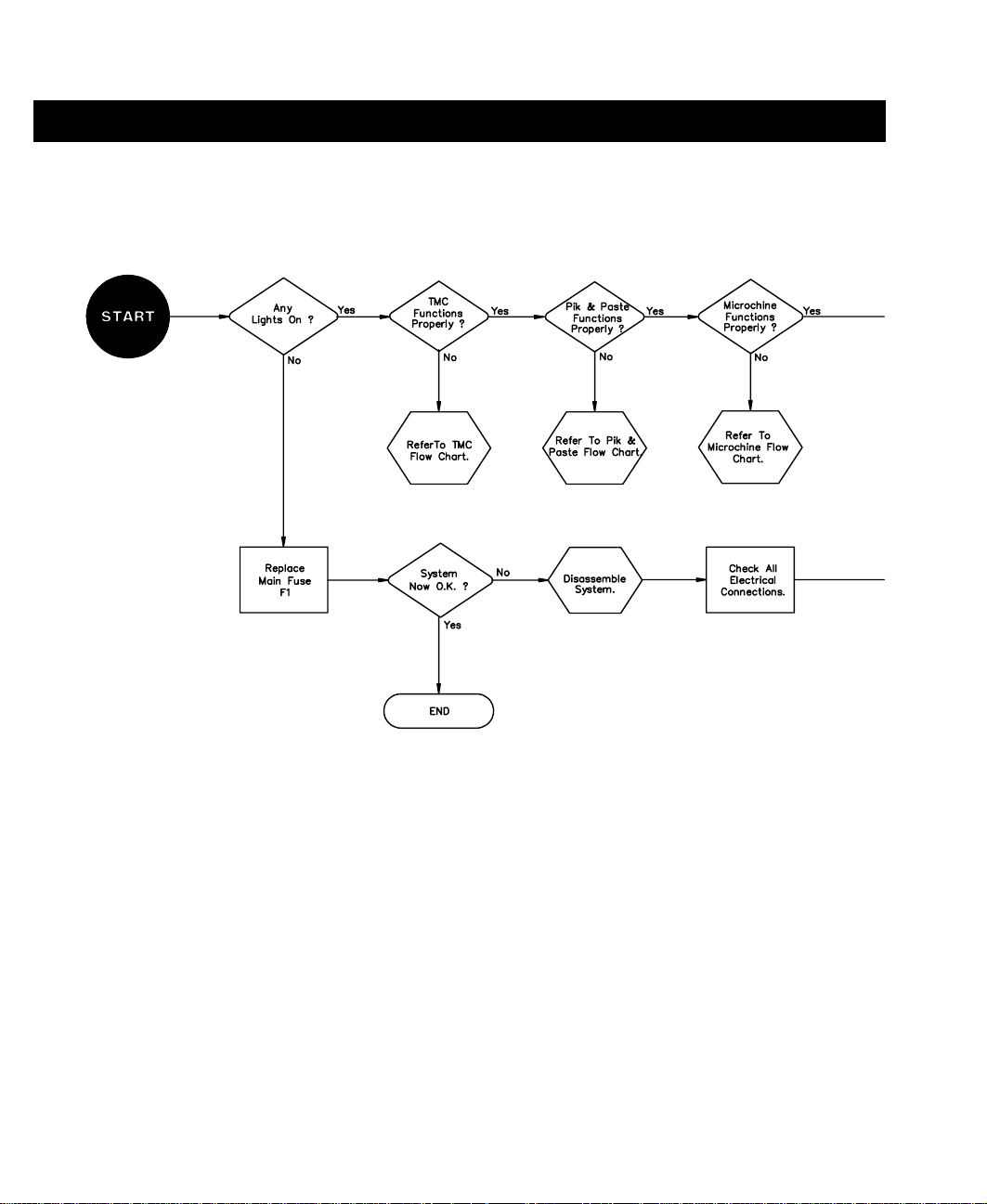
REPAIR
POWER
Figure 16. Power Flow Chart
40
Page 46
REPAIR
41
Page 47
REPAIR
TMC
I.
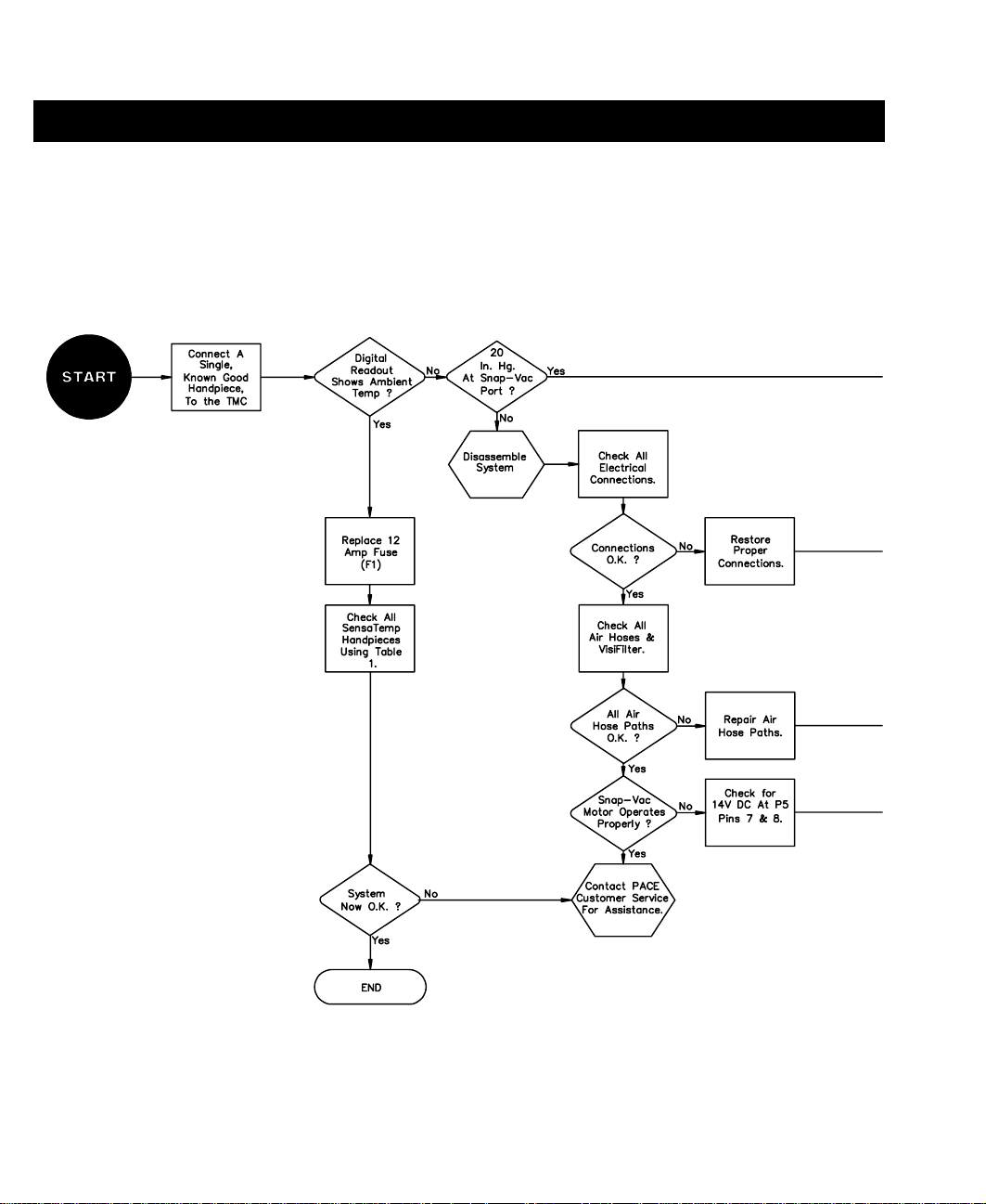
Figure 17. Thermal Management Center Malfunction Flow Chart
42
Page 48

REPAIR
43
Page 49
REPAIR
PIK & PASTE
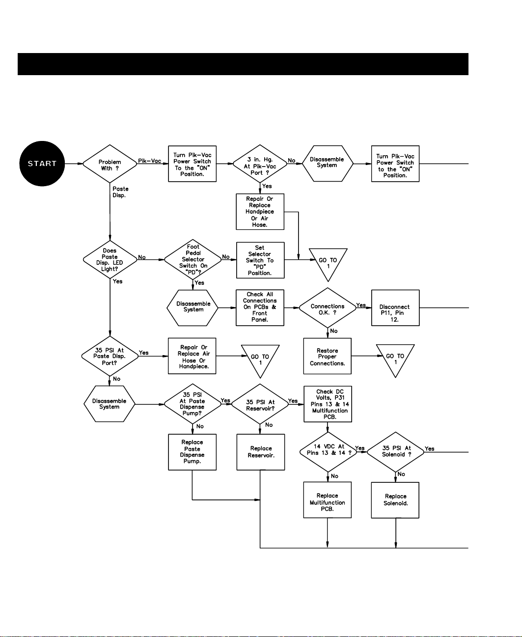
Figure 18. Pik & Paste Malfunction Flow Chart
44
Page 50

REPAIR
45
Page 51
REPAIR
MICROCHINE
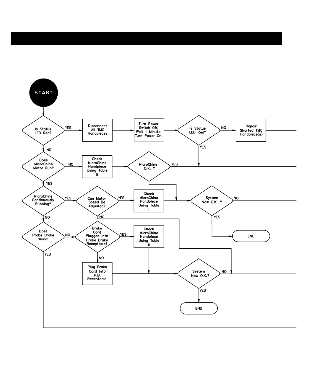
Figure 19. MicroChine Malfunction Flow Chart
46
Page 52

REPAIR
47
Page 53

REPAIR
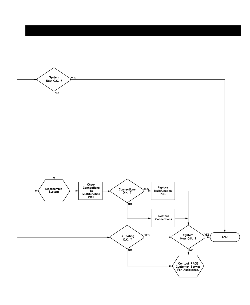
PULSE PLATE
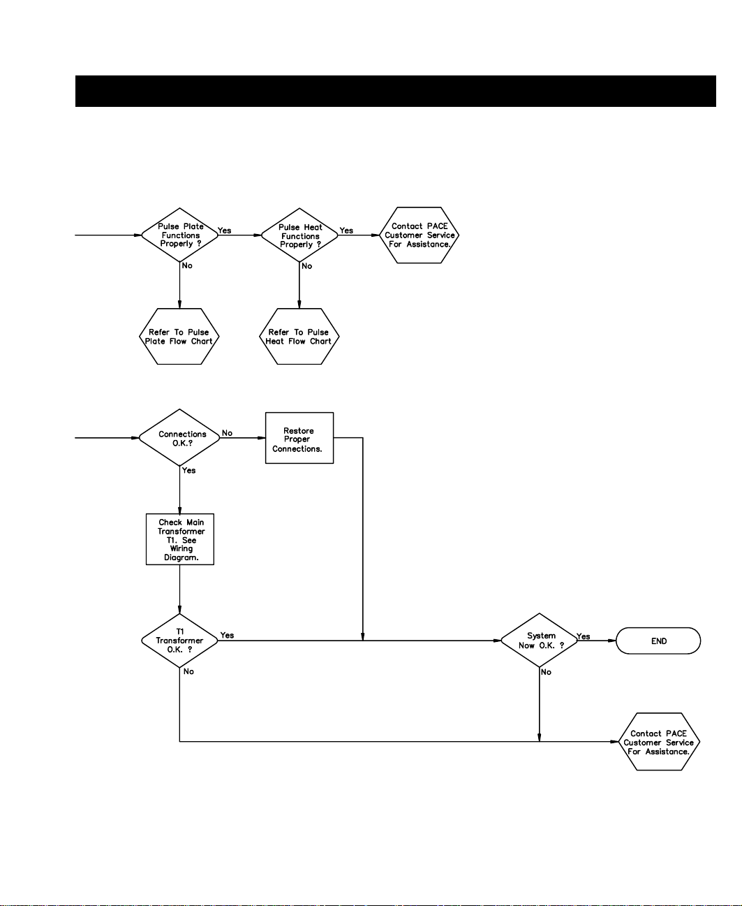
Figure 20. Pulse Plate Malfunction Flow Chart
48
Page 54
REPAIR
49
Page 55

REPAIR
PULSE HEAT
Figure 21. Pulse Heat Malfunction Flow Chart
50
Page 56

REPAIR
51
Page 57
REPAIR
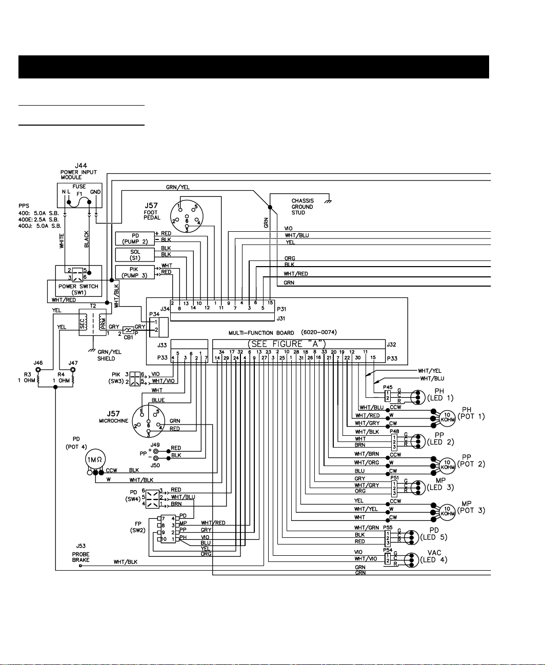
WIRING DIAGRAM
Figure 22. PPS 400, PPS 400J, PPS 400E Wiring Diagram
52
Page 58

REPAIR
53
Page 59
REPAIR
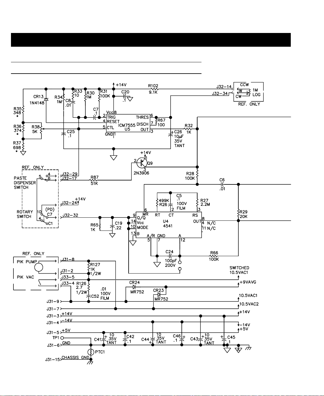
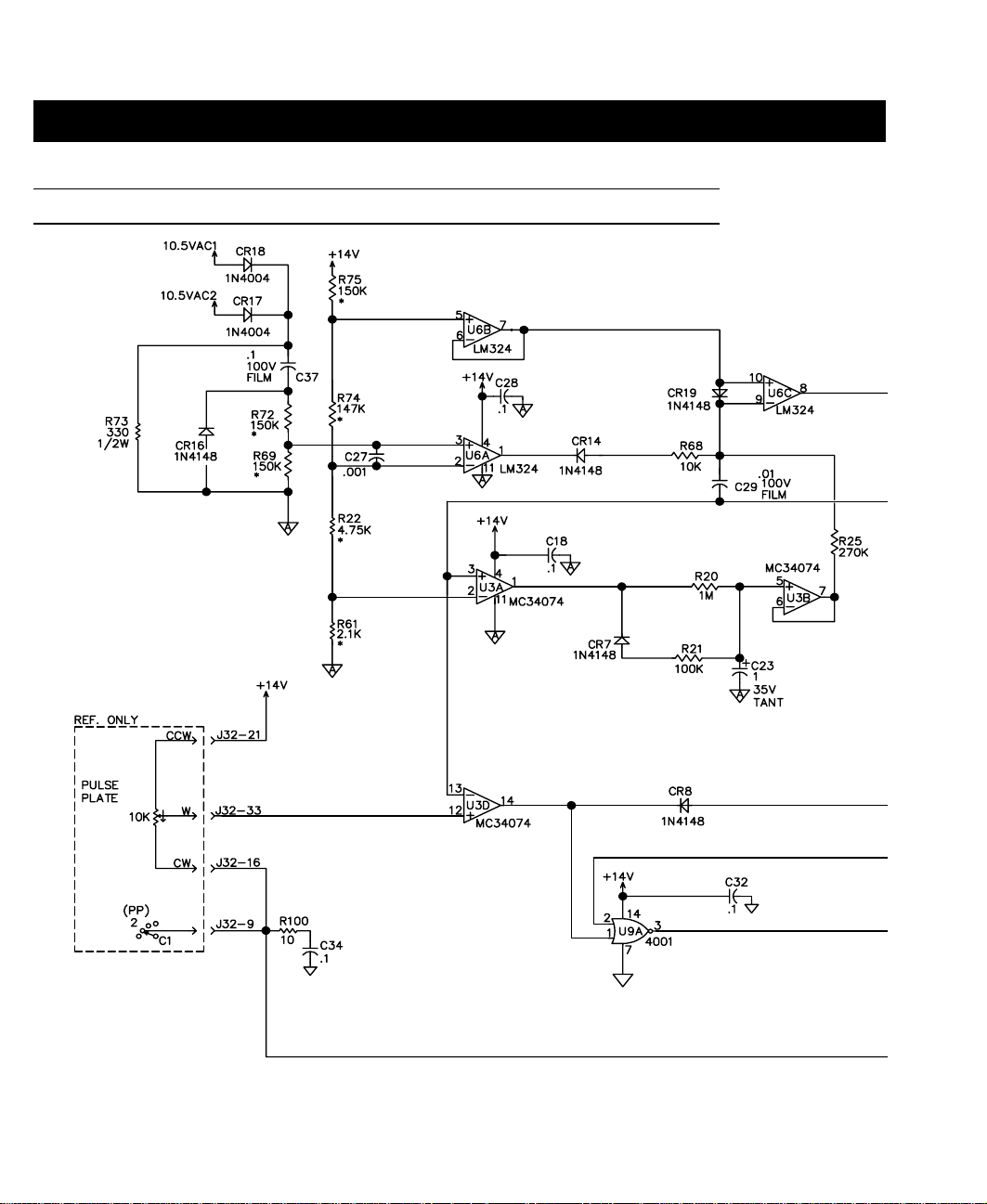
MULTIFUNCTION PCB ASSEMBLY SCHEMATIC
Figure 23. Multifunction PCB Assembly Schematic
54
Sheet 1 of 3
Page 60
REPAIR
55
Page 61
REPAIR
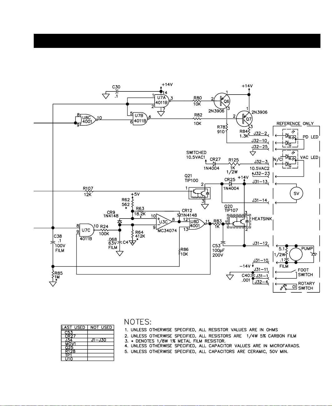
MULTIFUNCTION PCB ASSEMBLY SCHEMATIC CONT'D
Figure 23. Multifunction PCB Assembly Schematic Cont'd
56
Sheet 2 of 3
Page 62

REPAIR
57
Page 63

REPAIR
MULTIFUNCTION PCB ASSEMBLY SCHEMATIC CONT'D
Figure 23. Multifunction PCB Assembly Schematic Cont'd
58
Sheet 3 of 3
Page 64

REPAIR
59
Page 65

REPAIR
MICROPROCESSOR PCB ASSEMBLY SCHEMATIC
Figure 24. Microprocessor PCB Assembly Schematic
60
Sheet 1 of 2
Page 66

REPAIR
61
Page 67

REPAIR
MICROPROCESSOR PCB ASSEMBLY SCHEMATIC CONT'D
Figure 24. Microprocessor PCB Assembly Schematic Cont'd
62
Sheet 2 of 2
Page 68

REPAIR
63
Page 69

REPAIR
DISPLAY PCB ASSEMBLY SCHEMATIC
Figure 25. Display PCB Assembly Schematic
64
Page 70

REPAIR
65
Page 71
REPAIR
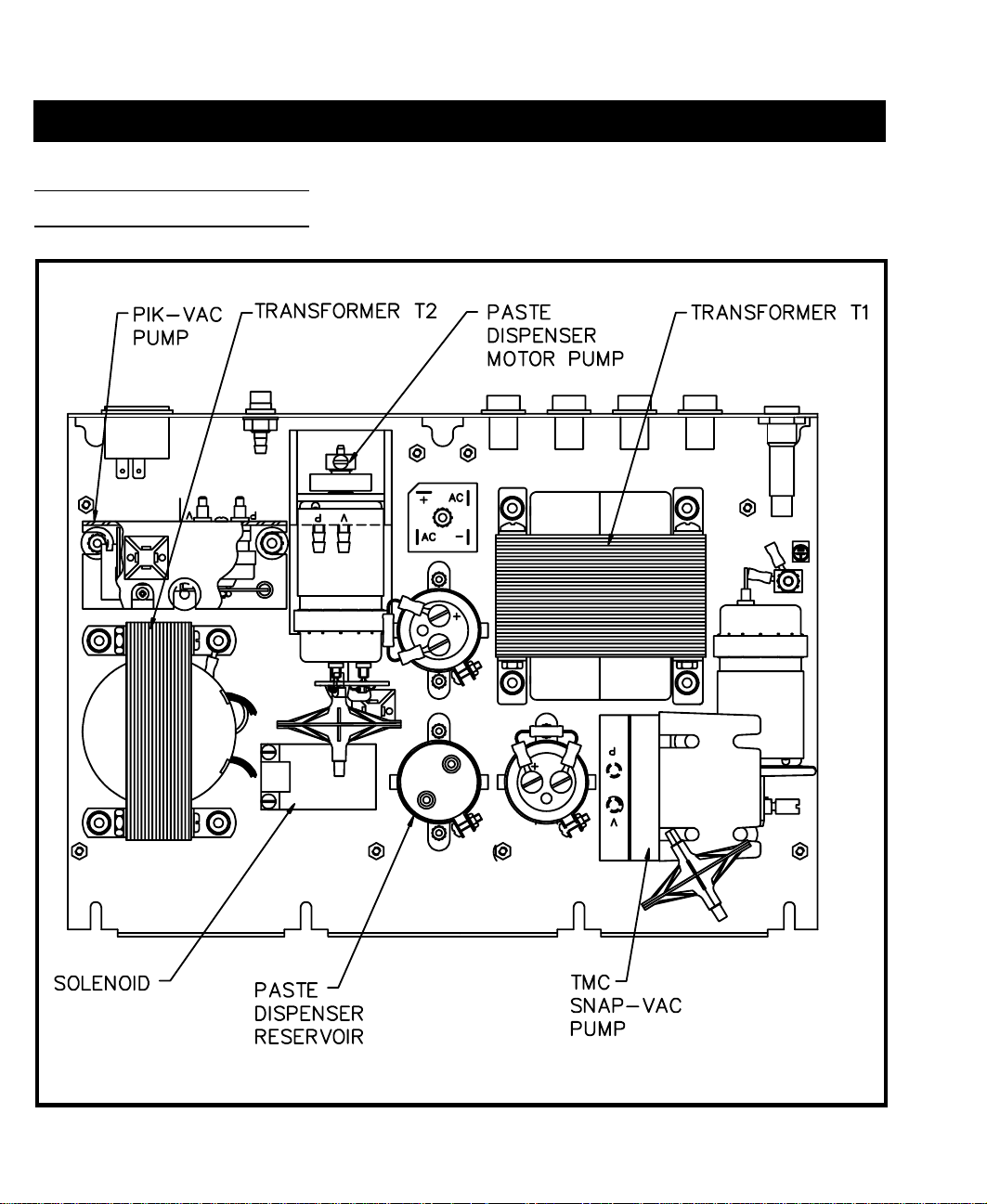
ASSEMBLY DRAWING
Figure 26. Assembly Drawing
66
Page 72

REPAIR
Figure 27. Assembly Drawing Cont'd
67
Page 73

REPAIR
AIR HOSE ROUTING
Figure 28. Air Hose Routing
68
Page 74

REPLACEMENT PARTS
POWER SOURCE
Listed below are the power source parts which may be ordered directly from PACE sales or your local
authorized PACE distributor. Refer to Table IV plus Figures 29-31. For handpiece and accessory replacement
parts, refer to Tables V, VI and VII or the associated Operation and Maintenance Manual. To obtain parts other
than those shown, contact PACE Customer Service directly at Telephone (301) 490-9860, Fax (301) 604-9215.
PART NUMBER
ITE
NO. DESCRIPTION
PPS 400
PPS 400J
PPS 400E
1 Main Power Switch 1157-0052 1157-0052
2 Fuse (F1), 5.0 Amp, Time Lag 1159-0253
2.5 Amp, Time Lag 1159-0220
3 Fuse (F2), 12.0 Amp, Fast Acting 1159-0257 1159-0257
4 AC Power Receptacle, Fused 1207-0151 1207-0274
5 Fuseholder 1161-0012 1161-0012
6 Motor Pump Assembly, SNAP-VAC 1336-0028 1336-0028
7 Motor Pump Assembly, Paste Disp. 1336-0027 1336-0027
8 Pump Assembly, Pik-Vac 1334-0021 1334-0021
9 Microprocessor PCB Assembly 6020-0072 6020-0072
10 Multifunction PCB Assembly 6020-0074 6020-0074
11 Display PCB Assembly 6020-0073 6020-0073
12 Pressure Reservoir 1140-0034 1140-0034
13 Solenoid, 12 Volt 1194-0016 1194-0016
VisiFilter, External (installed between Snap-Vac
14
Port & handpiece air hose)
1309-0028 1309-0028
15 VisiFilter Replacement Elements 1309-0027-P50 1309-0027-P50
16 VisiFilter, Internal (located inside power source) 1309-0020 1309-0020
Table IV. Power Source Replacement Parts
69
Page 75

REPLACEMENT PARTS
POWER SOURCE CONT'D
Figure 29. Power Source Replacement Parts
70
Page 76
REPLACEMENT PARTS
Figure 30. Power Source Replacement Parts Cont'd
71
Page 77

REPLACEMENT PARTS
Figure 31. Power Source Replacement Parts Cont'd
72
Page 78

POWER SOURCE ACCESSORIES
REPLACEMENT PARTS
ITEM
NO. DESCRIPTION
Power Cord
1
PRC 2000/J (100 VAC & 115 VAC Systems) 1332-0094
PRC 2000E (230 VAC Export Systems) 1332-0093
Foot Pedal 6008-0115
2
Paste Dispenser Kit 6993-0152
3
Tip Redi-Rak 6021-0007
4
Handpiece Redi-Rak 6019-0023
5
Tip & Temperature Chart Holder Assembly 1257-0186-P1
6
Cleaning Station (Complete) 6021-0006
7
8
9
10
Fiber Cleaning Tool 1100-0232
Fiber Filler, Replacement 1127-0013
Sponge Cleaning Tool 1100-0233
PART
NUMBER
11
12
13
14
15
16
Table V. Power Source Accessories
SX Tip & Tool Stand (for air handpieces) 6019-0044
SP Tip & Tool Stand (for SP handpieces) 6019-0043
ThermoTweez Tip & Tool Stand 6019-0046
Paste Dispenser Cubby 6019-0038
SMR Cubby 6019-0022
Sponge Filler, Replacement 4021-0006
73
Page 79

REPLACEMENT PARTS
HANDPIECES
ITEM
NO. DESCRIPTION
1 SX-70 Sodr-X-Tractor Handpiece 6010-0077-P1
2 Heater & Seal Assembly 6010-0080-P1
3 Glass Chamber 1265-0009-P1
4 Filter 1309-0018
5 Heater Set Screw 1348-0547
6 AdapTip 1360-0083-P1
7 SX-65A Sodr-X-Tractor Handpiece 6010-0073-P1
8 Heater & Seal Assembly 6010-0074-P1
9 Glass Chamber 1265-0009-P1
10 Filter 1309-0018
11 Heater Set Screw 1348-0547
12 SP-2A Sodr-Pen Soldering Iron Handpiece (54 Watts) 6025-0014-P1
13 Heater Assembly 6010-0086-P1
14 Heater Set Screw 1348-0547
15 SP-1A Sodr-Pen Soldering Iron Handpiece (37 Watts) 6025-0013-P1
PART
NUMBER
16 Heater Assembly 6010-0085-P1
17 Heater Set Screw 1348-0547
18 TJ-70 Mini ThermoJet Handpiece 7023-0002-P1
19 Heater Assembly 6010-0084-P1
20 Heater Set Screw 1348-0547
Table VI. Replacement Handpieces
74
Page 80

REPLACEMENT PARTS
ITEM
NO. DESCRIPTION
21 TP-65 ThermoPik Handpiece 7024-0001-P1
22 Heater Assembly 6010-0081-P1
23 Heater Set Screw 1348-0547
24 Vacuum Cups - - - - - - 25 4.4mm (0.175") O.D. 1121-0382-P5
26 7.6mm (0.300") O.D. 1121-0383-P5
27 12.7mm (0.500") O.D. 1121-0384-P5
28 TT-65 ThermoTweez Handpiece 7025-0001-P1
29 Heater Assembly With Sensor 6010-0082-P1
30 Heater Assembly Without Sensor 6010-0083-P1
31 Heater Set Screw 1348-0547
32 Cushion Grip Kit 6993-0155
33 Replacement Pads For Cushion Grips 1317-0029-P2
34 Tip Alignment Tool 1100-0234
35 PV-65 Pik-Vac Handpiece 7027-0001-P1
36 Metal Tip, 45° Angle 1121-0413-P5
PART
NUMBER
37 Vacuum Cups & Tips; See TP-65 Handpiece - - - - - - - - - 38 MC-65 MicroChine Handpiece 7026-0001-P1
39 Probe Brake Patch Cord 1332-0159
40 Deluxe Tool Kit 6005-0013
PULSE HEAT HANDPIECES
41 CT-15 ConducTweez Handpiece 7020-0001-P1
42 TW-15 ResisTweez Handpiece 7009-0005-P1
43 TS-15 StripTweez Handpiece 7012-0002-P1
44 LF-15 LapFlo Handpiece 7013-0004-02-P1
45 Universal Power Cord 7000-0023
46 Tip Screw, 2-56 x 5/32" Lg. (used on items 41 & 42) 1405-0182
Table VI. Replacement Handpieces Cont'd
75
Page 81

REPLACEMENT PARTS
HANDPIECE ACCESSORIES
ITEM
NO. DESCRIPTION
1 VisiFilter (replaceable element) 1309-0028
2 VisiFilter Replacement Elements 1309-0027-P50
3 Tubing, Clear PVC, 66" Lg. 1342-0001-14
4 Tubing, Clear PVC, 1 inch long 1325-0003-07
5 Tubing, Silicone, Translucent, 54" Lg. 1342-0001-13
6 Hose Clamps 1321-0085-01-P6
7 Cable Marker Kit 6993-0136
8 Quick Change Hose Mount, Female 1259-0086
9 Quick Change Hose Mount, Male 1259-0087
10 Bristle Brush 1127-0002
11 Wire Brush, 3/16" Diameter 1127-0014
12 Wire Brush, 1/8" Diameter 1127-0006
13 Tip Cleaner Kit 6993-0151
14 Tip Tool 1100-0206
15 PACE Screwdriver 1100-0230
PART
NUMBER
Table VII. Replacement Handpiece Accessories
76
Page 82

MANUAL IMPROVEMENT & COMMENT FORM
REPLACEMENT PARTS
Instructions
1.
Duplicate this form and submit comments on the copy. Keep the original to make future
comments.
2.
Complete all requested information.
3.
Submit completed form to: PACE Incorporated
Applications Engineering Fax: (301) 604 - 8782
9893 Brewers Court
Laurel MD 20723-1990 U.S.A.
Document Nbr:
Nature of Change (Identify page and paragraph and include proposed rewrite, if possible.)
5050-0344
Revision Level:
C
Date of Submission:
Reason for Recommendation
Submitter:
Name: Company or Organization:
Mailing Address: Telephone (Include Area Code)
Voice:
Fax:
77
 Loading...