

Page 1
NF 50 & NF 100
Nitrogen Farm
MANUAL NO. 8881-0100
REV. A
Page 2

TABLE OF CONTENTS
Introduction …………………………………………………………... 3
Specification ……………………………………………………………. 4
Parts Identification…. …………………………………………………… 5
Safety/features…………………………………………………………… 6
Set-Up/Start-Up………………………………………………………….. 7
Maintenance/Filter Replacement ………………………………………. 8
Spare Parts ……………………….……………………………………... 9
PACE Worldwide Warranty……………………………………………... 10
Equipment Warranty Registration ………………………………………… 11
READ THE SAFETY AND APPLICATIONS INFORMATION SECTION IN THE OPERATION AND MAINTENANCE
MANUAL THOROUGHLY BEFORE INSTALLING AND USING YOUR NITROGEN FARM SYSTEM.
CAUTION
Use of this Manual
This manual will provide the user with the basic information to properly operate and maintain the PACE
NF 50 & NF 100 Nitrogen Farm. If you encounter any difficulty operating your system or have any
questions, call your local authorized PACE dealer or contact PACE Applications Engineering directly at the
United Kingdom Office on: Tel. (44) 01908 277666, Fax (44) 01908 277777, or PACE Technical Support at
the U.S. Office on: Tel: (301) 490-9860, Fax (301 490-0193.
The compact, high performance single station N² generator (NF 100) will generate Nitrogen Gas at a
maximum concentration level of 99.9%. This system should be used in conjunction with NF 50 N² Flow
Control Unit. The NF 50 & NF 100 represents the latest technology in affordable Nitrogen Generation.
FAILURE TO COMPLY WITH THE APPLICATION AND MAINTENANCE GUIDELINES, FILTER REPLACEMENT
SCHEDULES, MONITORING RECOMMENDATIONS AND SAFETY GUIDELINES CONTAINED HEREIN AND
IN OTHER RELEVANT PRODUCT SAFETY LITERATURE (I.E., MATERIALS SAFETY DATA SHEETS) PROVIDED
WITH THE SUBSTANCES AND EQUIPMENT COULD RESULT IN RISK OF SERIOUS INJURY, FIRE OR
EXPLOSION.
WARNING
2
Page 3

Introduction
Lead Free solders do not behave or look like their lead containing counterparts. As our industry changes
over to Lead Free solders, individual PCB assemblers will need to address several issues relating to hand
soldering & rework. These issues include:
• Higher melting temperatures - which mistakenly lead to operators increasing equipment
operating temperatures. Higher operating temperatures do not make the process quicker; they
can actually slow it down.
• Poor wetting and spreading properties — Additional time is required when working with Lead
Free solders, they do not spread or wet like lead containing solders do. Operators must slow
down.
• Difficult to work with — Bridging and insufficient solder defects are common, even for
experienced operators, leading to operator frustration and poor quality.
• Dull grainy finish — makes inspection difficult.
The use of nitrogen assisted soldering equipment helps to mitigate the problems associated with using
Lead Free solders. Nitrogen helps on two fronts. First, it creates an inert environment around the
soldering tip, reducing the potential for the tip to oxidize. Second, it assists in the soldering process at
the PCB level by purging oxygen from the immediate area which reduces or eliminates the formation of
oxidation on the work site. This not only reduces the amount of flux that is required, but also helps to
improve wetting, spreading and leaves a finish that is shinier and less grainy.
PACE’s nitrogen assisted soldering systems pass the nitrogen through or around the heater before it is
directed to the work site. This “pre-heats” the immediate area which can also help to reduce thermal
shock to the component leads and to components themselves. Pre-heating also allows for the use of
lower, safer and more effective soldering temperatures.
The compact high-performance Single Station N² Generator (NF 100) will generate nitrogen gas at a
maximum concentration level of 99.9%. The NF 100 should be used in conjunction with the NF 50 N²
Flow Control Unit.
Environmental Specifications
Ambient operating temperature 0ºC to 50º (32ºF to 122ºF)
Storage temperature -40ºC to 125ºC (-40ºF to 257ºF)
Ambient operating humidity 90% relative humidity max non-
condensing
Storage humidity 90% relative humidity max non-
condensing
3
Page 4
Specifications
NF 50 N² Flow Control Unit NF 100 Single Station N² Farm
8110-0050 8110-0100
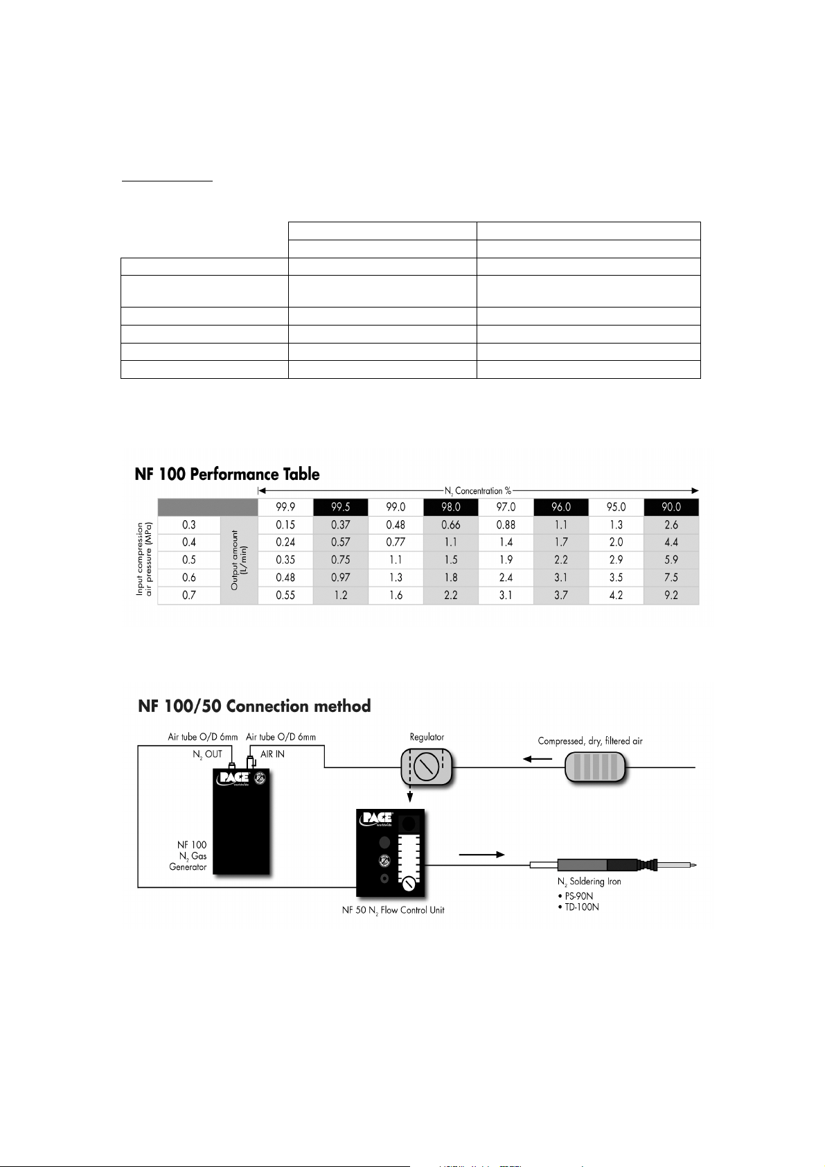
Max N² Flow Rate N/A *9.2 L/min
Max No of Soldering
Stations N/A 1
Max Input Air Pressure N/A 7 bar/101.5 psi
Power Source No Electrical Power Required No Electrical Power Required
Outline Dimensions 100x90x150mm (4"x3.5"x6") 100x90x300mm (4"x3.5"x12")
Weight 0.5Kg (1.1 lbs) 2Kg (4.4 lbs)
*This figure is based on 90% nitrogen enriched airflow at 7 bar/101.5 psi, temp 25ºC
4
Page 5

NF 100
Parts Identification
Flow Rate
Controller
N² On/Off
Tap
N² Outlet
(to N²
handpiece)
NF 50
N² Out
(to NF 50)
N² Inlet
(from NF 100)
Compressed Air Valve
(On/Off)
NF 50 Mounting
Brackets
NF 50 & NF 100 shown
with optional ST 70
5
Page 6

Safety
PACE Nitrogen Farms are designed to utilize the latest polyimide hollow fiber membrane technology to
allow the generation of nitrogen from compressed air. The input compressed air pressure must not
exceed 7 bar/101.5 psi, it is important to ensure that all compressed air hoses and fittings are
maintained and in good working order.
Disclaimer
PACE hereby disclaims all responsibility for any personal injury, property damage, fine, citation or
penalty imposed by any government or private entity which results from any use, misuse or misapplication of this product, failure of the user to regularly maintain the product according to the
recommended guidelines, or failure to adequately monitor input and/or output air and the ambient
workplace environment for the presence of harmful levels of gases, fumes and particulates.
Compliance with all applicable environmental and personal safety regulations is the sole responsibility
of the user and adequate self-monitoring of exhaust air released into the atmosphere or the workplace
as well as monitoring of the ambient workplace air is strongly recommended.
To insure continued effective performance, the following guidelines must be followed:
The basic principle of these products are that as compressed air flows through the hollow fibers
contained within the membrane body, oxygen is selectively allowed to permeate through the fiber wall
to atmosphere. This results in a nitrogen rich gas being obtained at the output of the hollow fiber
membrane.
There are three main factors determining the removal of oxygen from the nitrogen rich air:-
a) Temperature - if this is maintained at close to 25ºC then it can be ruled out of further
calculations of oxygen.
b) Flow rate — increasing the flow rate through the unit increases the level of oxygen present in the
output.
c) Pressure — increasing the pressure reduces the level of oxygen present in the output.
Features
• The NF 100 is able to achieve Nitrogen purities of up to 99.9% on demand when set up with the
NF 50 N² Flow Control Unit.
• Extremely quick set-up times. Because the system can be connected to an existing compressed
airline, it can be positioned in minutes and is very portable.
• Low running costs. The NF 50 & NF 100 requires no power source other than compressed air.
• Using conventional bottled nitrogen can result in a nitrogen imbalance in the workplace. This
system recycles oxygen, maintaining the correct balance of oxygen & nitrogen in the workplace.
The NF 50 & NF 100 contains no moving parts so do not give rise to noise or dust. No internal
(re)calibration is required.
6
Page 7

FAILURE TO COMPLY WITH THE APPLICATION AND MAINTENANCE GUIDELINES, FILTER REPLACEMENT
SCHEDULES, MONITORING RECOMMENDATIONS AND SAFETY GUIDELINES CONTAINED HEREIN AND
IN OTHER RELEVANT PRODUCT SAFETY LITERATURE (I.E., MATERIALS SAFETY DATA SHEETS) PROVIDED
WITH THE SUBSTANCES AND EQUIPMENT COULD RESULT IN RISK OF SERIOUS INJURY, FIRE OR
EXPLOSION.
Set up
WARNING
Set Up
The NF 50 & NF 100 have been designed for ease of use. The following are recommended guidelines for
setting up your system. If you have any specific questions that this section does not cover, please consult
your PACE Representative or call PACE directly.
Follow the connection method diagram on page 4.
Place NF 100 Single Station N² Farm on a workbench, as close to the work area as possible. Attach NF
50 N² Flow Control Unit to NF 100 via mounting brackets (if desired) as shown on page 5, Parts
identification. Connect suitable N² compatible handpiece to N² outlet on NF 50. Connect 6mm Push-Fit
pneumatic hose from N² outlet on NF 100 to N² inlet on NF 50.
Optional Solder Station can be placed below NF 50 as shown on page 5.
The NF 100 should be connected to a clean, dry, filtered, compressed air line at a maximum pressure of
7 bar/101.5 psi. Supply pressures should be regulated to the NF 100 at a lower value than the
compressors hysteresis to ensure constant operating pressure. The air supply should have no chemical,
lubricant or particulate matter added to the airline. It is however acceptable to use both dry and
lubricated compressors. Connection to the airline is made via a 6mm Push-Fit valve on top of the NF
100. (see figure on page 5)
PACE recommends that you add externally to the system, a membrane dryer to be in-line with incoming
compressed air supply.
Start-Up
• Ensure the system pressure regulator is closed.
• Close Flow Rate Controller on NF 50.
• Turn-on the compressed air supply to NF 100.
• Open the system pressure regulator until gauge reads a nominal 7-bar (101.5 psi).
• Open Compressed Air Valve on NF 100.
• Turn N² Tap on NF 50 to “On” position.
• Open Flow Rate Controller on NF 50 until desired rate is achieved (3 LPM is the recommended
starting pressure).
• Run for at least 20 minutes to allow system to stabilize before use.
Shut-Down
• Turn Compressed Air Valve on NF 100 to closed position.
• Leave open Flow Rate Controller on NF 50 until nitrogen has stopped flowing from the outlet,
then close Flow Rate Regulator.
• Turn N² On/Off Tap (on NF 50) to “Off” position.
Once running, both the flow rate regulator and the pressure regulator can control the level of nitrogen.
7
Page 8

ENSURE THAT THE COMPRESSED AIR RESERVOIR IS COMPLETELY DRAINED BEFORE ATTEMPTING TO
REMOVE ANY PNUEMATIC AIR LINE FROM SYSTEM SET UP.
WARNING
Maintenance
The NF 50 & NF 100 require no maintenance other than the replacement of the external (optional)
compressed air filters on a once yearly basis, or sooner depending on the quality of the input
compressed air. The filters are essential to maintain the integrity of the separator. The separator will
also need to be replaced from time to time; this will depend on the quality of the input compressed air,
product usage and purity of nitrogen required (approx separator life based on average use is 18-24
months).
NF 100 Separator Replacement Procedure
1. ENSURE UNIT IS DISCONNECTED FROM AIR SUPPLY!
2. Remove screws (x10) from both sides of NF 100 housing.
3. Locate N² separator module.
4. Remove retaining brackets to free N² separator.
5. Disconnect pipes & fittings from both N² separator at top & bottom. This is done by pushing in
surrounding flange of fitting and pulling out pipe.
6. Remove N² separator from NF 100 housing.
7. Fit new separator by following points 2-6 in reverse. Ensure that when fitting pipes into
connectors they are securely located.
THE SYSTEM MUST BE CONNECTED TO A CLEAN, DRY AND FILTERED AIR SUPPLY REGULATED TO 7.0
BAR (101.5 psi), SEE SPECIFICATIONS. CONNECTION TO A CONTAMINATED AIR SUPLY OR ONE WITH
PRESSURE IN EXCESS OF 8.5 BAR (123 psi) MAY CAUSE DAMAGE TO THIS SYSTEM.
CAUTION
8
Page 9

Parts Lists
NF 50 Replacement Part List
Description Part No.
Housing 8115-0055
Flow Control Meter 8115-0044
Bulkhead connector 8115-0051
Shut off valve - knob 8115-0053
1/8 Elbow connector 8115-0025
6mm Pipe 8115-0013
Grey Elbow Connector 8115-0058
Valve knob bracket 8115-0057
NF 100 Replacement Parts List
Description Part No.
Nitrogen Separator 8115-0050
Housing 8115-0054
3/8 Elbow connector 8115-0020
Bulkhead connector 8115-0051
Valve connector 8115-0052
6mm Pipe 8115-0013
Brackets 8115-0056
Clamp 8882-0581
PACE N² Compatible Handpieces
Part Number Description
6993-0272-P1 TD-100 N² Handpiece Kit (IntelliHeat)
6010-0156-P1 TD-100 N² Handpiece only (IntelliHeat)
6993-0273-P1 TD-100 N² Handpiece Kit (HeatWise/TempWise)
6010-0155-P1 TD-100 N² Handpiece only (HeatWise/TempWise)
6993-0274-P1 PS-90 N² Handpiece Kit (IntelliHeat)
6010-0157-P1 PS-90 N² Handpiece only (IntelliHeat)
6993-0275-P1 PS-90 N² Handpiece Kit (SensaTemp)
6010-0116-P1 PS-90 N² Handpiece only (SensaTemp)
Service
Please contact PACE or your Local Authorised PACE Distributor for service & repair.
9
Page 10

PACE WORLDWIDE LIMITED WARRANTY
PACE warrants to the first user that Products manufactured by it and supplied hereunder are free of
defects in materials and workmanship for a period of: (1) year from the date of receipt by such user. This
Warranty as applied to blowers and motor pumps is limited to a period of six (6) months. Monitors,
computers and other brand equipment supplied but not manufactured by PACE are covered under their
respective manufacturer’s warranty in lieu of this Warranty.
This warranty does not cover wear and tear under normal use, repair or replacement required as a
result of misuse, improper application, mishandling or improper storage. Consumable items such as
tips, heaters, filters etc. which wear out under normal use are excluded. Failure to perform
recommended routine maintenance, alterations or repairs made other than in accordance with PACE’s
directions, or removal or alteration of identification markings in any way will void this warranty. This
warranty is available only to the first user, but the exclusions and limitations herein apply to all persons
and entities.
PACE MAKES NO OTHER WARRANTY, EXPRESS OR IMPLIED, AND MAKES NO WARRANTY OF
MERCHANTABILITY OR FITNESS FOR A PARTICULAR PURPOSE.
PACE will, at its option, repair or replace any defective products at its facility or other location approved
by it at no charge to user, or provide parts without charge for installation by the user in the field at user’s
expense and risk. User will be responsible for all costs of shipping equipment to PACE or other location
for warranty service.
EXCEPT FOR THE REMEDY ABOVE DESCRIBED, UNLESS OTHERIWSE REQUIRED BY APPLICABLE LAW, PACE
WILL HAVE NO OTHER OBLIGATION WITH REGARD TO ANY BREACH OF WARRANTY OR OTHER CLAIM WITH
RESPECT TO THE PRODUCTS, OR LIABILITY FOR ANY DIRECT, INDIRECT, CONSEQUENTIAL, OR INCIDENTAL
LOSS OR DAMAGE CAUSED BY OR OCCURRING IN CONNECTION WITH ANY OF THE PRODUCTS.
Warranty service may be obtained by contacting the appropriate PACE Company or local Authorised
PACE distributor as set forth below to determine if return of any item is required, of if repairs can be
made by the user in the field.
Defective products may not be returned to PACE without a Service Authorization (“SA”) Number.
Any warranty or other claim with respect to the products must be made in writing delivered to PACE (or
local Authorised PACE Distributor for Buyers outside the USA and the United Kingdom) within a
reasonable time of the expiration date of this warranty with sufficient evidence of purchase and date of
receipt, otherwise user’s rights under this warranty shall be deemed waived.
For Customer’s in the USA & Canada: For Customer’s in Europe:
PACE USA PACE Europe Limited
9030 Junction Drive 13 Tanners Drive
Annapolis Junction Blakelands
MD 20701 Milton Keynes
USA MK14 5BU
United Kingdom
Tel: (301) 490-9860 (44) 01908 277666
Fax: (301) 498-3252 (44) 01908 277777
All other Customers: Local Authorized PACE Distributor
10
Page 11

To register your purchase with PACE, fill in the form below and mail or FAX to the applicable PACE
address listed above.
EQUIPMENT WARRANTY REGISTRATION CARD
Date
Model No.
Purchased from
Company Name
Mailing Address
Telephone number with area code
Fax Number with area code
Internet Address
Full Name
Authorized Signature, Title
Serial No. Of Receipt
www.paceworldwide.com
11
Page 12

PACE Incorporated retains the right to make changes to specifications contained herein at any time,
without notice. Contact your local PACE Authorised Distributor or PACE Incorporated to obtain the latest
specifications.
The following are trademarks and/or service marks of PACE, Incorporated, MD, USA:
INSTACAL™, FUMEFLO™, HEATWISE™, PACEWORLDWIDE™, PERMAGROUND™, POWERPORT™,
POWERMODULE™, TEMPWISE™, TIP-BRITE™, AUTO-OFF™ and TEKLINK™
The following are registered trademarks and/or service marks of PACE, Incorporated, Annapolis
Junction, Maryland, USA:
ARM-EVAC
SODR- X-TRACTOR®, THERMOFLO®, THERMOJET®, THERMOTWEEZ®, VISIFILTER®,
THERMO-DRIVE®, TOOLNET®.
®, FLO-D-SODR®, MINIWAVE®, PACE®, SENSATEMP®, SNAP-VAC®, SODRTEK®,
PACE products meet or exceed all applicable military and civilian EOS/ESD, temperature stability and
other specifications including MIL STD 2000, ANSI/JSTD 001, IPC7711 and IPC A-610.
PACE USA PACE Europe Limited
9030 Junction Drive 13 Tanners Drive
Annapolis Junction Blakelands
MD 20701 Milton Keynes
USA MK14 5BU
United Kingdom
Tel: (301) 490-9860 (44) 01908 277666
Fax: (301) 498-3252 (44) 01908 277777
12
 Loading...